WO2014017018A1 - 分析用デバイス - Google Patents
分析用デバイス Download PDFInfo
- Publication number
- WO2014017018A1 WO2014017018A1 PCT/JP2013/003913 JP2013003913W WO2014017018A1 WO 2014017018 A1 WO2014017018 A1 WO 2014017018A1 JP 2013003913 W JP2013003913 W JP 2013003913W WO 2014017018 A1 WO2014017018 A1 WO 2014017018A1
- Authority
- WO
- WIPO (PCT)
- Prior art keywords
- reagent
- separation
- chamber
- separation chamber
- measurement
- Prior art date
Links
Images


Classifications
-
- C—CHEMISTRY; METALLURGY
- C12—BIOCHEMISTRY; BEER; SPIRITS; WINE; VINEGAR; MICROBIOLOGY; ENZYMOLOGY; MUTATION OR GENETIC ENGINEERING
- C12Q—MEASURING OR TESTING PROCESSES INVOLVING ENZYMES, NUCLEIC ACIDS OR MICROORGANISMS; COMPOSITIONS OR TEST PAPERS THEREFOR; PROCESSES OF PREPARING SUCH COMPOSITIONS; CONDITION-RESPONSIVE CONTROL IN MICROBIOLOGICAL OR ENZYMOLOGICAL PROCESSES
- C12Q1/00—Measuring or testing processes involving enzymes, nucleic acids or microorganisms; Compositions therefor; Processes of preparing such compositions
- C12Q1/60—Measuring or testing processes involving enzymes, nucleic acids or microorganisms; Compositions therefor; Processes of preparing such compositions involving cholesterol
-
- B—PERFORMING OPERATIONS; TRANSPORTING
- B01—PHYSICAL OR CHEMICAL PROCESSES OR APPARATUS IN GENERAL
- B01L—CHEMICAL OR PHYSICAL LABORATORY APPARATUS FOR GENERAL USE
- B01L3/00—Containers or dishes for laboratory use, e.g. laboratory glassware; Droppers
- B01L3/50—Containers for the purpose of retaining a material to be analysed, e.g. test tubes
- B01L3/502—Containers for the purpose of retaining a material to be analysed, e.g. test tubes with fluid transport, e.g. in multi-compartment structures
- B01L3/5027—Containers for the purpose of retaining a material to be analysed, e.g. test tubes with fluid transport, e.g. in multi-compartment structures by integrated microfluidic structures, i.e. dimensions of channels and chambers are such that surface tension forces are important, e.g. lab-on-a-chip
- B01L3/50273—Containers for the purpose of retaining a material to be analysed, e.g. test tubes with fluid transport, e.g. in multi-compartment structures by integrated microfluidic structures, i.e. dimensions of channels and chambers are such that surface tension forces are important, e.g. lab-on-a-chip characterised by the means or forces applied to move the fluids
-
- B—PERFORMING OPERATIONS; TRANSPORTING
- B01—PHYSICAL OR CHEMICAL PROCESSES OR APPARATUS IN GENERAL
- B01L—CHEMICAL OR PHYSICAL LABORATORY APPARATUS FOR GENERAL USE
- B01L3/00—Containers or dishes for laboratory use, e.g. laboratory glassware; Droppers
- B01L3/50—Containers for the purpose of retaining a material to be analysed, e.g. test tubes
- B01L3/502—Containers for the purpose of retaining a material to be analysed, e.g. test tubes with fluid transport, e.g. in multi-compartment structures
- B01L3/5027—Containers for the purpose of retaining a material to be analysed, e.g. test tubes with fluid transport, e.g. in multi-compartment structures by integrated microfluidic structures, i.e. dimensions of channels and chambers are such that surface tension forces are important, e.g. lab-on-a-chip
- B01L3/502753—Containers for the purpose of retaining a material to be analysed, e.g. test tubes with fluid transport, e.g. in multi-compartment structures by integrated microfluidic structures, i.e. dimensions of channels and chambers are such that surface tension forces are important, e.g. lab-on-a-chip characterised by bulk separation arrangements on lab-on-a-chip devices, e.g. for filtration or centrifugation
-
- G—PHYSICS
- G01—MEASURING; TESTING
- G01N—INVESTIGATING OR ANALYSING MATERIALS BY DETERMINING THEIR CHEMICAL OR PHYSICAL PROPERTIES
- G01N33/00—Investigating or analysing materials by specific methods not covered by groups G01N1/00 - G01N31/00
- G01N33/48—Biological material, e.g. blood, urine; Haemocytometers
- G01N33/483—Physical analysis of biological material
- G01N33/487—Physical analysis of biological material of liquid biological material
- G01N33/49—Blood
- G01N33/491—Blood by separating the blood components
-
- B—PERFORMING OPERATIONS; TRANSPORTING
- B01—PHYSICAL OR CHEMICAL PROCESSES OR APPARATUS IN GENERAL
- B01L—CHEMICAL OR PHYSICAL LABORATORY APPARATUS FOR GENERAL USE
- B01L2200/00—Solutions for specific problems relating to chemical or physical laboratory apparatus
- B01L2200/10—Integrating sample preparation and analysis in single entity, e.g. lab-on-a-chip concept
-
- B—PERFORMING OPERATIONS; TRANSPORTING
- B01—PHYSICAL OR CHEMICAL PROCESSES OR APPARATUS IN GENERAL
- B01L—CHEMICAL OR PHYSICAL LABORATORY APPARATUS FOR GENERAL USE
- B01L2200/00—Solutions for specific problems relating to chemical or physical laboratory apparatus
- B01L2200/16—Reagents, handling or storing thereof
-
- B—PERFORMING OPERATIONS; TRANSPORTING
- B01—PHYSICAL OR CHEMICAL PROCESSES OR APPARATUS IN GENERAL
- B01L—CHEMICAL OR PHYSICAL LABORATORY APPARATUS FOR GENERAL USE
- B01L2300/00—Additional constructional details
- B01L2300/08—Geometry, shape and general structure
- B01L2300/0803—Disc shape
-
- B—PERFORMING OPERATIONS; TRANSPORTING
- B01—PHYSICAL OR CHEMICAL PROCESSES OR APPARATUS IN GENERAL
- B01L—CHEMICAL OR PHYSICAL LABORATORY APPARATUS FOR GENERAL USE
- B01L2300/00—Additional constructional details
- B01L2300/08—Geometry, shape and general structure
- B01L2300/0861—Configuration of multiple channels and/or chambers in a single devices
- B01L2300/087—Multiple sequential chambers
-
- B—PERFORMING OPERATIONS; TRANSPORTING
- B01—PHYSICAL OR CHEMICAL PROCESSES OR APPARATUS IN GENERAL
- B01L—CHEMICAL OR PHYSICAL LABORATORY APPARATUS FOR GENERAL USE
- B01L2400/00—Moving or stopping fluids
- B01L2400/04—Moving fluids with specific forces or mechanical means
- B01L2400/0403—Moving fluids with specific forces or mechanical means specific forces
- B01L2400/0409—Moving fluids with specific forces or mechanical means specific forces centrifugal forces
-
- B—PERFORMING OPERATIONS; TRANSPORTING
- B01—PHYSICAL OR CHEMICAL PROCESSES OR APPARATUS IN GENERAL
- B01L—CHEMICAL OR PHYSICAL LABORATORY APPARATUS FOR GENERAL USE
- B01L2400/00—Moving or stopping fluids
- B01L2400/06—Valves, specific forms thereof
- B01L2400/0688—Valves, specific forms thereof surface tension valves, capillary stop, capillary break
-
- B—PERFORMING OPERATIONS; TRANSPORTING
- B01—PHYSICAL OR CHEMICAL PROCESSES OR APPARATUS IN GENERAL
- B01L—CHEMICAL OR PHYSICAL LABORATORY APPARATUS FOR GENERAL USE
- B01L3/00—Containers or dishes for laboratory use, e.g. laboratory glassware; Droppers
- B01L3/50—Containers for the purpose of retaining a material to be analysed, e.g. test tubes
- B01L3/508—Containers for the purpose of retaining a material to be analysed, e.g. test tubes rigid containers not provided for above
- B01L3/5088—Containers for the purpose of retaining a material to be analysed, e.g. test tubes rigid containers not provided for above confining liquids at a location by surface tension, e.g. virtual wells on plates, wires
-
- G—PHYSICS
- G01—MEASURING; TESTING
- G01N—INVESTIGATING OR ANALYSING MATERIALS BY DETERMINING THEIR CHEMICAL OR PHYSICAL PROPERTIES
- G01N35/00—Automatic analysis not limited to methods or materials provided for in any single one of groups G01N1/00 - G01N33/00; Handling materials therefor
- G01N35/00029—Automatic analysis not limited to methods or materials provided for in any single one of groups G01N1/00 - G01N33/00; Handling materials therefor provided with flat sample substrates, e.g. slides
- G01N2035/00099—Characterised by type of test elements
- G01N2035/00158—Elements containing microarrays, i.e. "biochip"
-
- G—PHYSICS
- G01—MEASURING; TESTING
- G01N—INVESTIGATING OR ANALYSING MATERIALS BY DETERMINING THEIR CHEMICAL OR PHYSICAL PROPERTIES
- G01N35/00—Automatic analysis not limited to methods or materials provided for in any single one of groups G01N1/00 - G01N33/00; Handling materials therefor
- G01N2035/00465—Separating and mixing arrangements
- G01N2035/00495—Centrifuges
-
- G—PHYSICS
- G01—MEASURING; TESTING
- G01N—INVESTIGATING OR ANALYSING MATERIALS BY DETERMINING THEIR CHEMICAL OR PHYSICAL PROPERTIES
- G01N35/00—Automatic analysis not limited to methods or materials provided for in any single one of groups G01N1/00 - G01N33/00; Handling materials therefor
- G01N35/02—Automatic analysis not limited to methods or materials provided for in any single one of groups G01N1/00 - G01N33/00; Handling materials therefor using a plurality of sample containers moved by a conveyor system past one or more treatment or analysis stations
- G01N35/04—Details of the conveyor system
- G01N2035/0401—Sample carriers, cuvettes or reaction vessels
- G01N2035/0403—Sample carriers with closing or sealing means
-
- G—PHYSICS
- G01—MEASURING; TESTING
- G01N—INVESTIGATING OR ANALYSING MATERIALS BY DETERMINING THEIR CHEMICAL OR PHYSICAL PROPERTIES
- G01N35/00—Automatic analysis not limited to methods or materials provided for in any single one of groups G01N1/00 - G01N33/00; Handling materials therefor
- G01N35/02—Automatic analysis not limited to methods or materials provided for in any single one of groups G01N1/00 - G01N33/00; Handling materials therefor using a plurality of sample containers moved by a conveyor system past one or more treatment or analysis stations
- G01N35/04—Details of the conveyor system
- G01N2035/0439—Rotary sample carriers, i.e. carousels
- G01N2035/0446—Combinations of the above
- G01N2035/0449—Combinations of the above using centrifugal transport of liquid
Definitions
- the present invention relates to an analysis device used for analyzing a liquid collected from a living organism.
- a measurement chamber connected to the chamber via a first branch path, a storage chamber connected to the separation chamber via a second branch path, and the like are formed.
- the analytical device takes in the liquid to be inspected from the sample supply port and then rotates or swings around the rotation axis to mix or centrifuge the liquid contained in the mixing cavity.
- a specific component is separated by a reagent, the liquid treated in the separation chamber is transferred to the measurement chamber, and used for reading to access the liquid in the measurement chamber.
- a liquid to be examined such as blood is taken into the main body case from the sample supply port and supplied to the separation chamber via the supply path.
- the sample is treated with a reagent and separated into two types, one of which is supplied to the measurement chamber via the first branch path, and the other is supplied to the storage chamber via the second branch path. It comes to be supplied.
- the measurement chamber is irradiated with light, and the amount of transmitted light is measured to analyze blood.
- HDL cholesterol in blood which is generally expressed as good cholesterol, and when this component is measured, when liquid extracted from blood is supplied to the separation chamber, it is placed in a dry state in the separation chamber in advance.
- the separation process for the measurement of HDL cholesterol is performed by the reagent used.
- the present invention provides an analytical device that can hold a reagent more reliably than before until the liquid to be inspected arrives in the separation chamber even when the analytical device is used in a humid environment. With the goal.
- the analysis device of the present invention includes a microchannel structure supply path for transferring a liquid to be inspected taken from a sample supply port provided in the main body case toward a measurement chamber, and a liquid to be inspected.
- a separation chamber in which a reagent for processing the component to be examined is disposed is formed, a storage chamber connected to the separation chamber via a first branch path is formed, and the separation chamber is connected via a second branch path
- the outer peripheral edge of the reagent holding part in which the reagent is arranged is partially connected to an outward peeling part.
- the peeling portion is partially connected to the outer peripheral edge of the reagent holding portion, the holding force acting on the reagent droplet is partially applied to the portion where the peeling portion is connected.
- the reagent spreads to the outer peripheral edge of the reagent holding part and starts shrinking based on drying from that state.
- the outer periphery of the reagent is not in contact with the outer peripheral edge of the reagent holding portion in the portion of the peeling portion connected to the outer peripheral edge of the reagent holding portion.
- the shrinkage of the reagent continues until the part of the outer periphery of the reagent that touches the outer peripheral edge of the reagent holding part is also peeled inward. As a result, the reagent is small and has a small thickness. Drying is completed with the
- the sample is reliably processed by the reagent, and thereby the measurement value in the measurement chamber becomes stable, and the reliability of the measurement can be improved.
- the perspective view of the device for analysis in Embodiment 1 of the present invention is an exploded perspective view of the main part of the analysis device according to the first embodiment of the present invention.
- FIG. 6 is a partially enlarged view showing a state before the reagent is held in the reagent holding unit of FIG.
- A An enlarged cross-sectional view showing a reagent immediately after dropping in a conventional example, and (b) a plan view thereof.
- A An enlarged cross-sectional view showing the initial drying state of the reagent in the conventional example, and (b) a plan view thereof.
- A Sectional view showing the drying state of the reagent in the conventional example, and (b) plan view thereof
- A An enlarged cross-sectional view showing the final state of reagent drying in a conventional example, and (b) a plan view thereof.
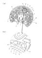
- FIG. 1 shows a perspective view of the completed analytical device.
- the external shape of the analysis device 1 is circular, and is composed of a main body case 2 in which micro flow paths such as a measurement chamber, a separation chamber, and a flow path are formed, and a cover 3 that is pivotally supported by the main body case 2 at one end. Yes.
- the planar shape of the analyzing device 1 with the cover 3 closed is circular.
- FIG. 2 shows a state in which the sample supply port 4 provided in the main body case 2 is exposed by opening the cover 3.
- the sample supply port 4 is a supply port for supplying blood, which is an example of a sample, into the body case 2.
- FIG. 3 is an exploded perspective view of the main body case 2.
- the main body case 2 includes a base substrate 2b and a cover substrate 15 bonded to the lower surface of the base substrate 2b.
- the cover substrate 15 closes the opening surfaces of various recesses formed on the lower surface of the base substrate 2b to form microchannels such as measurement chambers 5, 9, 10, separation chambers 6, and channels.
- a connecting portion 15 a that engages with a rotation driving device (not shown) that drives the analyzing device 1 around the axis 20.
- the blood is drawn into the main body case 2 by the capillary force of the flow path connected to the sample supply port 4.
- the blood drawn into the main body case 2 is separated into plasma and blood cells by the centrifugal force at the portion A in FIG. Thereafter, only plasma is supplied to the mixing chamber B of FIG.
- the mixing chamber B In the mixing chamber B, the dilution liquid supplied from the dilution chamber 7 and the plasma are mixed.
- the diluted solution / plasma mixed solution is supplied from the mixing chamber B to the separation chamber 6 through the flow path.
- a separation reagent 8 is disposed in the separation chamber 6.
- sample solution supplied to the separation chamber 6 for example, HDL cholesterol, which is a plasma substance, is separated by the separation reagent 8, and in this separated state, the sample solution is supplied to the measurement chamber 5 via the mixing chamber 17 and the second branch channel 19. Supplied.
- a storage chamber 16 is connected to the separation chamber 6 via a mixing chamber 17 and a first branch path 18.
- the reaction reagent is arranged in the measurement chamber 5.
- the substance in plasma supplied to the measurement chamber 5 reacts with the reaction reagent. Thereafter, HDL cholesterol can be measured by irradiating the measurement chamber 5 with light.
- Separation reagent 8 for the measurement of HDL cholesterol is a precipitation reagent.
- the reaction reagent in the case of measuring HDL cholesterol is an HDL enzyme solution.
- the feature point in the present embodiment is that a substance in plasma (for example, HDL cholesterol) is separated in the separation chamber 6, and a separation reagent 8 is disposed for this separation.
- a substance in plasma for example, HDL cholesterol
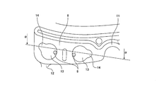
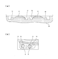
- a reagent holding portion 13 that protrudes downward is provided at the ceiling portion between the inlet 11 and the outlet 12.
- a separation reagent 8 is provided in the reagent holding unit 13. More specifically, as can be understood from FIG. 5, the reagent holding portion 13 has a circular or substantially circular planar shape, and a part of the outer peripheral edge extends outwardly and below.
- the peeling part 14 which protrudes is connected.
- the planar shape of the peeling part 14 is circular or substantially circular, the height of the upper surface is the same as that of the reagent holding part 13, and the peeling part 14 and the reagent holding part 13 are integrally molded with the base substrate 2b.
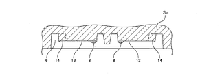
- the separation reagent 8 is placed in the reagent holding unit 13 in the steps of FIGS.
- the base substrate 2b is turned over so that the reagent holding portion 13 faces upward as shown in FIG. Then, the separation reagent 8 is dropped on the reagent holding unit 13.
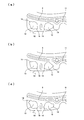
- the separation reagent 8 spreads along the outer peripheral edge of the reagent holding unit 13 as shown in FIG. It should be noted that a part of the outer periphery of the separation reagent 8 spreading in a circular shape in FIG. In the peeling portion 14, the outer periphery of the lower portion of the droplet of the separation reagent 8 is not in contact with the circular outer periphery of the reagent holding portion 13.
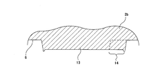
- the drying of the base substrate 2b in the state of FIGS. 8A and 8B where the separation reagent 8 is dropped is started, the shrinkage due to the drying of the dropped separation reagent 8 is caused by the circular shape of the reagent holding unit 13.
- the drying of the separation reagent 8 proceeds with the progress of FIGS. 9 and 10 as the drying time elapses.
- the portion in contact with the peripheral edge is continuously contracted so that the separation reagent 8 is peeled inward, and as a result, the separation reagent 8 is small as shown in FIG. Will be.
- the separation reagent 8 that has been dried in a small and thick state can be used even when the analytical device 1 is used in a high humidity state, or only the surface of the separation reagent 8 absorbs moisture and is fluidized. The inside of it does not reach moisture and does not fluidize. For this reason, even if centrifugal force is applied, it does not inadvertently flow out into the measurement chamber 5 or the storage chamber 16.
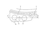
- a mixing chamber 17 that is a part of the separation chamber 6 is connected to the outlet 12 of the separation chamber 6, and the first branch path is connected to the mixing chamber 17.
- the storage chamber 16 is connected via 18 and the measurement chamber 5 is connected via the second branch 19.
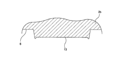
- FIGS. 14 to 16 show a conventional structure in which the peeling unit 14 is not connected to the reagent holding unit 13.
- the separation chamber 6 is shown.
- the entire outer periphery of the separation reagent 8 that has spread in a circular shape remains in contact with the circular outer periphery of the reagent holding unit 13, and as the drying time elapses.
- the outer dimensions of the separation reagent 8 are the same as the outer periphery of the reagent holding unit 13, but eventually the thickness of the separation reagent 8 decreases with the progress of FIGS. 18 (a), (b) and FIGS. 19 (a), (b). As a result, as shown in FIG. 20, the separation reagent 8 is wide and the drying is terminated in a thin state.
- the entire surface of the separation reagent 8 absorbs moisture and is fluidized. A part of 8 flows out to the storage chamber 16 and the measurement chamber 5 through the mixing chamber 17.
- the separation reagent 8 has flowed out in this way, the separation process is not reliably performed, and as a result, the measurement value in the measurement chamber 5 becomes unstable and the reliability of the measurement is lowered.
- an exfoliating portion 14 that extends outward is connected.
- the reagent holding unit 13 protrudes downward from the ceiling of the separation chamber 6, but may have a shape recessed upward from the ceiling surface of the separation chamber 6. The reason why such a reagent holding unit 13 is provided on the ceiling of the separation chamber 6 is to allow the sample liquid to smoothly flow on the floor surface of the separation chamber 6.
- a circular or substantially circular peeling portion 14 is connected to a part of the outer peripheral edge of the reagent holding portion 13, but instead of the circular peeling portion 14, FIG.
- a triangular or substantially triangular peeling part 14 is connected to a part of the outer peripheral edge of the reagent holding part 13, or a part of the outer peripheral edge of the reagent holding part 13 as shown in FIG. You may connect the peeling part 14 of square shape or substantially square shape.
- the number of peeling portions 14 with respect to one reagent holding portion 13 is 1, but the outer peripheral edge of the reagent holding portion 13 as shown in FIGS. 13 (a) (b) (c) If it is a part, a plurality of peeling portions 14 may be provided.
- the present invention contributes to the improvement of the reliability of various component analysis using the analytical device.
Landscapes
- Health & Medical Sciences (AREA)
- Chemical & Material Sciences (AREA)
- Life Sciences & Earth Sciences (AREA)
- Engineering & Computer Science (AREA)
- Hematology (AREA)
- General Health & Medical Sciences (AREA)
- Analytical Chemistry (AREA)
- Biomedical Technology (AREA)
- Molecular Biology (AREA)
- Physics & Mathematics (AREA)
- Organic Chemistry (AREA)
- Immunology (AREA)
- Biophysics (AREA)
- Biochemistry (AREA)
- Dispersion Chemistry (AREA)
- Clinical Laboratory Science (AREA)
- Chemical Kinetics & Catalysis (AREA)
- Wood Science & Technology (AREA)
- Zoology (AREA)
- Proteomics, Peptides & Aminoacids (AREA)
- General Physics & Mathematics (AREA)
- Pathology (AREA)
- Medicinal Chemistry (AREA)
- Food Science & Technology (AREA)
- Urology & Nephrology (AREA)
- Ecology (AREA)
- Biotechnology (AREA)
- Microbiology (AREA)
- Bioinformatics & Cheminformatics (AREA)
- General Engineering & Computer Science (AREA)
- Genetics & Genomics (AREA)
- Automatic Analysis And Handling Materials Therefor (AREA)
- Investigating Or Analysing Biological Materials (AREA)
Abstract
Description
図1は完成した分析用デバイスの斜視図を示す。
実施の形態1においては、試薬保持部13の外周縁の一部に、円形状または略円形状の剥離部14を連結したが、円形状の剥離部14に代わって、図12(a)に示すように試薬保持部13の外周縁の一部に三角形状または略三角形状の剥離部14を連結したり、図12(b)に示すように試薬保持部13の外周縁の一部に、四角形状または略四角形状の剥離部14を連結しても良い。
上記の各実施の形態においては、一つの試薬保持部13に対する剥離部14の数が1であったが、図13(a)(b)(c)に示すように試薬保持部13の外周縁の一部であれば、複数の剥離部14を設けてもよい。
2 本体ケース
2b ベース基板
3 カバー
4 試料供給口
5 測定室
6 分離室
7 希釈室
8 分離試薬
9 測定室
10 測定室
11 入口
12 出口
13 試薬保持部
14 剥離部
15 カバー基板
15a 連結部
16 貯留室
17 混合室
18 第1分岐路
19 第2分岐路
Claims (5)
- 本体ケースの内部に、前記本体ケースに設けられた試料供給口から取り込んだ検査対象の液体を測定室に向かって移送するマイクロチャネル構造の供給路、検査対象の液体の中の検査対象成分を処理する試薬が配置されている分離室が形成され、
第1分岐路を介して前記分離室に接続された貯留室が形成され、
第2分岐路を介して前記分離室に接続された測定室が形成され、
前記分離室で前記試薬によって処理された液体を、遠心力によって前記測定室に移送し、前記測定室における液体にアクセスする読み取りに使用される分析用デバイスにおいて、
前記試薬が配置される試薬保持部の外周縁には、外方に広がる剥離部が部分的に連結されている
分析用デバイス。 - 前記剥離部の平面形状が、円形状または略円形状、または三角形状または略三角形状、または四角形状または略四角形状である
請求項1に記載の分析用デバイス。 - 前記試薬保持部は、分離室の天井から下方に突出している
請求項1または2に記載の分析用デバイス。 - 前記試薬保持部は、分離室の天井から上方に窪ませた
請求項1または2に記載の分析用デバイス。 - 前記試薬保持部の試薬を分離試薬とし、前記測定室には、反応試薬を設けた
請求項1~4のいずれかに記載の分析用デバイス。
Priority Applications (4)
| Application Number | Priority Date | Filing Date | Title |
|---|---|---|---|
| CN201380003605.XA CN103890591B (zh) | 2012-07-24 | 2013-06-24 | 分析用仪器 |
| EP13822288.0A EP2878951B1 (en) | 2012-07-24 | 2013-06-24 | Analyzing device |
| US14/114,994 US9145579B2 (en) | 2012-07-24 | 2013-06-24 | Analyzing device |
| JP2013541906A JP5705329B2 (ja) | 2012-07-24 | 2013-06-24 | 分析用デバイス |
Applications Claiming Priority (2)
| Application Number | Priority Date | Filing Date | Title |
|---|---|---|---|
| JP2012163387 | 2012-07-24 | ||
| JP2012-163387 | 2012-07-24 |
Publications (1)
| Publication Number | Publication Date |
|---|---|
| WO2014017018A1 true WO2014017018A1 (ja) | 2014-01-30 |
Family
ID=49996846
Family Applications (1)
| Application Number | Title | Priority Date | Filing Date |
|---|---|---|---|
| PCT/JP2013/003913 WO2014017018A1 (ja) | 2012-07-24 | 2013-06-24 | 分析用デバイス |
Country Status (5)
| Country | Link |
|---|---|
| US (1) | US9145579B2 (ja) |
| EP (1) | EP2878951B1 (ja) |
| JP (1) | JP5705329B2 (ja) |
| CN (1) | CN103890591B (ja) |
| WO (1) | WO2014017018A1 (ja) |
Cited By (5)
| Publication number | Priority date | Publication date | Assignee | Title |
|---|---|---|---|---|
| US10309976B2 (en) | 2014-06-30 | 2019-06-04 | Phc Holdings Corporation | Substrate for sample analysis, sample analysis device, sample analysis system, and program for sample analysis system |
| US10520521B2 (en) | 2014-06-30 | 2019-12-31 | Phc Holdings Corporation | Substrate for sample analysis, sample analysis device, sample analysis system, and program for sample analysis system |
| US10539582B2 (en) | 2014-06-30 | 2020-01-21 | Phc Holdings Corporation | Substrate for sample analysis, sample analysis device, sample analysis system, and method for removing liquid from liquid that contains magnetic particles |
| US10539583B2 (en) | 2014-12-12 | 2020-01-21 | Phc Holdings Corporation | Substrate for sample analysis, sample analysis device, sample analysis system, and program for sample analysis system |
| US10539560B2 (en) | 2014-06-30 | 2020-01-21 | Phc Holdings Corporation | Substrate for sample analysis, and sample analysis apparatus |
Families Citing this family (6)
| Publication number | Priority date | Publication date | Assignee | Title |
|---|---|---|---|---|
| WO2018187493A1 (en) | 2017-04-04 | 2018-10-11 | Yale University | Compositions and methods for in utero delivery |
| WO2020033951A1 (en) | 2018-08-10 | 2020-02-13 | Yale University | Compositions and methods for embryonic gene editing in vitro |
| WO2020257779A1 (en) | 2019-06-21 | 2020-12-24 | Yale University | Hydroxymethyl-modified gamma-pna compositions and methods of use thereof |
| WO2020257776A1 (en) | 2019-06-21 | 2020-12-24 | Yale University | Peptide nucleic acid compositions with modified hoogsteen binding segments and methods of use thereof |
| US20220280656A1 (en) | 2019-07-31 | 2022-09-08 | Yale University | Compositions and methods for treating sickle cell disease |
| EP4352226A1 (en) | 2021-06-07 | 2024-04-17 | Yale University | Peptide nucleic acids for spatiotemporal control of crispr-cas binding |
Citations (8)
| Publication number | Priority date | Publication date | Assignee | Title |
|---|---|---|---|---|
| JPH10501340A (ja) | 1994-06-06 | 1998-02-03 | アバクシス,インコーポレイテッド | 測定精度を改善するための改良サイホン |
| US20020045270A1 (en) * | 2000-09-01 | 2002-04-18 | Martin Schurenberg | Structured biosample support plates for mass spectroscopic analyses and procedures for manufacturing and use |
| JP2005028279A (ja) * | 2003-07-11 | 2005-02-03 | Seiko Epson Corp | 膜形成方法、デバイス製造方法、電気光学装置、並びに電子機器 |
| JP2006060076A (ja) * | 2004-08-20 | 2006-03-02 | Seiko Epson Corp | エッチング方法、微細構造体の製造方法、導電線の形成方法、薄膜トランジスタの製造方法及び電子機器の製造方法 |
| WO2007066518A1 (ja) * | 2005-12-08 | 2007-06-14 | Nec Corporation | 接液構造、液体の移動制御構造、および液体の移動制御方法 |
| JP2009098039A (ja) * | 2007-10-18 | 2009-05-07 | Panasonic Corp | 分析容器と分析装置 |
| JP2010210531A (ja) | 2009-03-12 | 2010-09-24 | Panasonic Corp | 分析用デバイス |
| JP2012122977A (ja) * | 2010-12-10 | 2012-06-28 | Fujifilm Corp | 分析チップ |
Family Cites Families (13)
| Publication number | Priority date | Publication date | Assignee | Title |
|---|---|---|---|---|
| US5242606A (en) * | 1990-06-04 | 1993-09-07 | Abaxis, Incorporated | Sample metering port for analytical rotor having overflow chamber |
| US5304348A (en) * | 1992-02-11 | 1994-04-19 | Abaxis, Inc. | Reagent container for analytical rotor |
| US5267401A (en) | 1992-07-24 | 1993-12-07 | Summagraphics Corporation | Method and apparatus for gauging reel diameters in a reel-to-reel sheet material transport system |
| JP2005028275A (ja) * | 2003-07-11 | 2005-02-03 | Seiko Epson Corp | 膜形成方法、デバイス製造方法、電気光学装置、並びに電子機器 |
| US7601386B2 (en) | 2003-07-11 | 2009-10-13 | Seiko Epson Corporation | Process for forming a film, process for manufacturing a device, electro-optical device and electronic equipment |
| US7691328B2 (en) * | 2003-10-03 | 2010-04-06 | National Institute For Materials Science | Chip using method and test chip |
| US20060182654A1 (en) * | 2005-02-16 | 2006-08-17 | Cumberland Brandi M | Sampling device and method for the rapid detection of proteins in mold, allergens of other protein-containing substances |
| WO2007006049A2 (en) * | 2005-07-06 | 2007-01-11 | The Regents Of The University Of California | Apparatuses, systems, and methods for isolating and separating biological materials |
| CN101541962A (zh) * | 2007-03-23 | 2009-09-23 | 株式会社东芝 | 核酸检测盒以及核酸检测装置 |
| JP5134313B2 (ja) | 2007-08-31 | 2013-01-30 | 株式会社シグマ | 電子機器用蓋 |
| JP5401542B2 (ja) * | 2008-06-19 | 2014-01-29 | ベーリンガー インゲルハイム マイクロパーツ ゲゼルシャフト ミット ベシュレンクテル ハフツング | 流体計量容器 |
| CN102981004B (zh) * | 2008-07-17 | 2014-01-01 | 松下电器产业株式会社 | 分析用器件及使用该分析用器件的分析方法 |
| EP2309266A1 (en) * | 2009-09-21 | 2011-04-13 | F. Hoffmann-La Roche AG | Method for carrying out reactions in an analytical device |
-
2013
- 2013-06-24 US US14/114,994 patent/US9145579B2/en active Active
- 2013-06-24 EP EP13822288.0A patent/EP2878951B1/en active Active
- 2013-06-24 CN CN201380003605.XA patent/CN103890591B/zh active Active
- 2013-06-24 JP JP2013541906A patent/JP5705329B2/ja active Active
- 2013-06-24 WO PCT/JP2013/003913 patent/WO2014017018A1/ja active Application Filing
Patent Citations (8)
| Publication number | Priority date | Publication date | Assignee | Title |
|---|---|---|---|---|
| JPH10501340A (ja) | 1994-06-06 | 1998-02-03 | アバクシス,インコーポレイテッド | 測定精度を改善するための改良サイホン |
| US20020045270A1 (en) * | 2000-09-01 | 2002-04-18 | Martin Schurenberg | Structured biosample support plates for mass spectroscopic analyses and procedures for manufacturing and use |
| JP2005028279A (ja) * | 2003-07-11 | 2005-02-03 | Seiko Epson Corp | 膜形成方法、デバイス製造方法、電気光学装置、並びに電子機器 |
| JP2006060076A (ja) * | 2004-08-20 | 2006-03-02 | Seiko Epson Corp | エッチング方法、微細構造体の製造方法、導電線の形成方法、薄膜トランジスタの製造方法及び電子機器の製造方法 |
| WO2007066518A1 (ja) * | 2005-12-08 | 2007-06-14 | Nec Corporation | 接液構造、液体の移動制御構造、および液体の移動制御方法 |
| JP2009098039A (ja) * | 2007-10-18 | 2009-05-07 | Panasonic Corp | 分析容器と分析装置 |
| JP2010210531A (ja) | 2009-03-12 | 2010-09-24 | Panasonic Corp | 分析用デバイス |
| JP2012122977A (ja) * | 2010-12-10 | 2012-06-28 | Fujifilm Corp | 分析チップ |
Cited By (5)
| Publication number | Priority date | Publication date | Assignee | Title |
|---|---|---|---|---|
| US10309976B2 (en) | 2014-06-30 | 2019-06-04 | Phc Holdings Corporation | Substrate for sample analysis, sample analysis device, sample analysis system, and program for sample analysis system |
| US10520521B2 (en) | 2014-06-30 | 2019-12-31 | Phc Holdings Corporation | Substrate for sample analysis, sample analysis device, sample analysis system, and program for sample analysis system |
| US10539582B2 (en) | 2014-06-30 | 2020-01-21 | Phc Holdings Corporation | Substrate for sample analysis, sample analysis device, sample analysis system, and method for removing liquid from liquid that contains magnetic particles |
| US10539560B2 (en) | 2014-06-30 | 2020-01-21 | Phc Holdings Corporation | Substrate for sample analysis, and sample analysis apparatus |
| US10539583B2 (en) | 2014-12-12 | 2020-01-21 | Phc Holdings Corporation | Substrate for sample analysis, sample analysis device, sample analysis system, and program for sample analysis system |
Also Published As
| Publication number | Publication date |
|---|---|
| JP5705329B2 (ja) | 2015-04-22 |
| EP2878951B1 (en) | 2019-11-20 |
| EP2878951A1 (en) | 2015-06-03 |
| EP2878951A4 (en) | 2015-07-22 |
| JPWO2014017018A1 (ja) | 2016-07-07 |
| CN103890591B (zh) | 2016-08-24 |
| US9145579B2 (en) | 2015-09-29 |
| US20140073041A1 (en) | 2014-03-13 |
| CN103890591A (zh) | 2014-06-25 |
Similar Documents
| Publication | Publication Date | Title |
|---|---|---|
| JP5705329B2 (ja) | 分析用デバイス | |
| US10016758B2 (en) | Rotatable cartridge for analyzing a biological sample | |
| JP4587298B2 (ja) | マイクロ流体デバイス内での粒子分離方法及び装置 | |
| US9808801B2 (en) | Rotatable cartridge for measuring a property of a biological sample | |
| US10307757B2 (en) | Rotatable cartridge with a metering chamber for analyzing a biological sample | |
| US11406979B2 (en) | Rotatable cartridge for processing and analyzing a biological sample and dispensing method therewith | |
| US20170176306A1 (en) | Blood collector with capillary structure | |
| JP5376429B2 (ja) | 分析用デバイスとこれを使用する分析装置および分析方法 | |
| WO2019146734A1 (ja) | 分離装置及び分離方法、分離デバイス、並びに検査装置及び検査方法 | |
| US20100233798A1 (en) | Centrifugal force-based microfluidic device and method of fabricating the same | |
| JP2009229243A (ja) | マイクロデバイス | |
| JP5137009B2 (ja) | マイクロチップの製造方法 | |
| JP2009115670A (ja) | 分析用デバイスとこれを使用する分析装置および分析方法 |
Legal Events
| Date | Code | Title | Description |
|---|---|---|---|
| ENP | Entry into the national phase |
Ref document number: 2013541906 Country of ref document: JP Kind code of ref document: A |
|
| WWE | Wipo information: entry into national phase |
Ref document number: 14114994 Country of ref document: US |
|
| WWE | Wipo information: entry into national phase |
Ref document number: 2013822288 Country of ref document: EP |
|
| 121 | Ep: the epo has been informed by wipo that ep was designated in this application |
Ref document number: 13822288 Country of ref document: EP Kind code of ref document: A1 |
|
| NENP | Non-entry into the national phase |
Ref country code: DE |