WO2014016903A1 - 面光源を有する照明モジュール及び照明システム - Google Patents
面光源を有する照明モジュール及び照明システム Download PDFInfo
- Publication number
- WO2014016903A1 WO2014016903A1 PCT/JP2012/068688 JP2012068688W WO2014016903A1 WO 2014016903 A1 WO2014016903 A1 WO 2014016903A1 JP 2012068688 W JP2012068688 W JP 2012068688W WO 2014016903 A1 WO2014016903 A1 WO 2014016903A1
- Authority
- WO
- WIPO (PCT)
- Prior art keywords
- address
- command
- lighting
- illumination
- control unit
- Prior art date
- Legal status (The legal status is an assumption and is not a legal conclusion. Google has not performed a legal analysis and makes no representation as to the accuracy of the status listed.)
- Ceased
Links
Images





Classifications
-
- H—ELECTRICITY
- H05—ELECTRIC TECHNIQUES NOT OTHERWISE PROVIDED FOR
- H05B—ELECTRIC HEATING; ELECTRIC LIGHT SOURCES NOT OTHERWISE PROVIDED FOR; CIRCUIT ARRANGEMENTS FOR ELECTRIC LIGHT SOURCES, IN GENERAL
- H05B45/00—Circuit arrangements for operating light-emitting diodes [LED]
- H05B45/60—Circuit arrangements for operating LEDs comprising organic material, e.g. for operating organic light-emitting diodes [OLED] or polymer light-emitting diodes [PLED]
-
- H—ELECTRICITY
- H05—ELECTRIC TECHNIQUES NOT OTHERWISE PROVIDED FOR
- H05B—ELECTRIC HEATING; ELECTRIC LIGHT SOURCES NOT OTHERWISE PROVIDED FOR; CIRCUIT ARRANGEMENTS FOR ELECTRIC LIGHT SOURCES, IN GENERAL
- H05B47/00—Circuit arrangements for operating light sources in general, i.e. where the type of light source is not relevant
- H05B47/10—Controlling the light source
- H05B47/175—Controlling the light source by remote control
- H05B47/18—Controlling the light source by remote control via data-bus transmission
- H05B47/184—Controlling the light source by remote control via data-bus transmission using digital multiplexed [DMX] communication protocols
-
- H—ELECTRICITY
- H05—ELECTRIC TECHNIQUES NOT OTHERWISE PROVIDED FOR
- H05B—ELECTRIC HEATING; ELECTRIC LIGHT SOURCES NOT OTHERWISE PROVIDED FOR; CIRCUIT ARRANGEMENTS FOR ELECTRIC LIGHT SOURCES, IN GENERAL
- H05B47/00—Circuit arrangements for operating light sources in general, i.e. where the type of light source is not relevant
- H05B47/10—Controlling the light source
- H05B47/175—Controlling the light source by remote control
- H05B47/198—Grouping of control procedures or address assignation to light sources
Definitions
- the present invention relates to a plurality of illumination modules having a surface light source, and an illumination system including a master device that controls the plurality of illumination modules.
- a light-emitting device using an organic EL panel having an organic EL element as a light-emitting source has been proposed.
- a light emitting device using an organic EL panel has a feature that there is no restriction in shape due to surface light emission, and such a feature cannot be obtained in other light emitting devices such as an LED (light emitting diode) light emitting device. Further development for practical application is expected.
- an organic EL panel as a light emitting source of a light emitting device is sandwiched between an anode made of a transparent conductive film such as ITO formed on a transparent substrate, a cathode made of a metal such as Al, and the anode and the cathode.
- an organic light emitting functional layer having an organic multilayer structure (Patent Document 1).
- the organic light emitting functional layer is made of an organic material, and is composed of, for example, a hole injection / transport layer, a light emitting layer, an electron transport layer, and an electron injection layer in order from the anode side. Can be formed.
- organic light emitting functional layers are formed in stripes so that high luminance can be obtained in the entire panel.
- tiling by arranging a plurality of such organic EL panels in a plane (called tiling), a new illumination form such as a shining ceiling or a shining wall becomes possible, and it is expected to provide new value in daily life. Has been.
- each of the plurality of organic EL panels is individually controlled to produce effect illumination on the entire ceiling or wall.
- two-dimensional significant information and patterns can be expressed by controlling luminance and color for each organic EL panel.
- DMX512-A standard is an illumination control technique suitable for controlling an organic EL panel that performs such illumination.
- the lighting system using the DMX512-A standard is premised on a configuration including one master device that controls lighting control and a plurality of lighting modules (slave devices) that receive lighting control.
- the master device transmits a command including control data to each of the plurality of lighting modules via a communication line.
- Each of the plurality of lighting modules including the organic EL panel receives a command and drives the organic EL panel according to control data in the command.
- tiling is an important application of a surface emitting panel such as an organic EL panel.
- the tiling surface visible to the user is only the light emitting surface of the organic EL panel, and the switches, the drive control unit and the wiring of the panel in the lighting module are hidden behind the panel, for example, the ceiling. Should be. Therefore, the address setting operation has to be completed before installation on the mounting surface of the lighting module, and there is a drawback that it is difficult to set or change the address after the lighting module is installed.
- the problem to be solved by the present invention is that the above-mentioned drawbacks are given as an example, and the address to each lighting module is clarified so that the correspondence between the position and address of each lighting module can be clarified by simple manual work. It is an object of the present invention to provide a lighting module and a lighting system that can be assigned.
- the illumination module of the invention receives the surface light source and the light emission control command transmitted from the master device via the communication line, and according to the control data for itself included in the received light emission control command.
- An illumination module including a drive control unit that drives and controls the surface light source, and includes an on / off switch to be connected to the communication line, and the on / off switch is integrally coupled to the surface light source and the drive control unit. It is characterized by being.
- the lighting system includes a master device that transmits a light emission control command, each having a surface light source, and the light emission control command transmitted from the master device is received and received via a communication line.
- a plurality of illumination modules each driving and controlling the surface light source according to control data for itself included in the light emission control command, the illumination system being provided in the master device and addressed at a predetermined timing Are sequentially set, and a transmission means for sending an address assignment command including the set address to the communication line, and a command receivable state in a predetermined order from the plurality of lighting modules in synchronization with the predetermined timing Switch means for setting one lighting module, wherein each of the plurality of lighting modules includes the switch.
- FIG. 1 It is a block diagram which shows the illumination system of the Example of this invention. It is sectional drawing of the surface light source in the illumination module of FIG. It is a figure which shows the command format of the asynchronous serial communication used with the illumination system of FIG. It is a figure which shows the command format of the original command of DMX512-A specification used with the illumination system of FIG. It is a sequence diagram of the address assignment operation
- a lighting control master 11 master device
- a plurality of lighting modules slave devices 12 0 to 12 n (where n is a positive integer) are provided.
- a communication line 13 is provided between the illumination control master 11 and the plurality of illumination modules 12 0 to 12 n .
- the illumination control master 11 is a controller that controls the operation of each of the plurality of illumination modules 12 0 to 12 n .
- the illumination control master 11 has a communication I / F (interface) unit 21 and a master communication control unit 22.
- the communication IF unit 21 is connected to the communication line 13 and transmits / receives commands to be described later for each of the plurality of illumination modules 12 0 to 12 n .
- the master communication control unit 22 is connected to the communication IF unit 21 and includes, for example, a microcomputer.
- the master communication control unit 22 generates a command for controlling the operation of each of the plurality of lighting modules 12 0 to 12 n and transmits the command to the communication I / F.
- the master communication control unit 22 interprets the content of the command received by the communication I / F unit 21 and creates a command for responding to the command.
- the operation unit 23 is connected to the master communication control unit 22, accepts a user input operation, and issues a command corresponding to the input operation to the master communication control unit 22.
- the operation unit 23 is provided outside the illumination control master 11 in the embodiment, but may be a part of the illumination control master 11.
- Each of the plurality of lighting modules 12 0 to 12 n is tiled on a ceiling, a wall, or the like as an organic EL panel having a surface light source 34 made of an organic EL element described later.
- Each of the plurality of illumination modules 12 0 to 12 n has the same configuration, and includes a communication I / F (interface) unit 31, a slave communication control unit 32, a light emission control unit 33, and a surface light source 34.
- the communication I / F unit 31, the slave communication control unit 32, and the light emission control unit 33 are drive control units for the surface light source 34.
- the communication I / F unit 31 is connected to the communication line 13 and transmits / receives a command to / from the lighting control master 11.
- the slave communication control unit 32 is separately connected to the communication I / F unit 31 and the light emission control unit 33, extracts the control data addressed to itself in the command received by the communication I / F unit 31, and outputs it to the light emission control unit 33.
- the slave communication control unit 32 interprets the contents of the command received by the communication I / F unit 31 and creates a command for responding to the command.
- the light emission control unit 33 is connected to the surface light source 34 and drives and controls the surface light source 34 according to control data supplied from the slave communication control unit 32.
- the slave communication control unit 32 and the light emission control unit 33 may be configured by a single microcomputer.
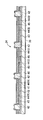
- the surface light source 34 has a transparent electrode 41 formed on a glass substrate 40 as an anode.
- the transparent electrode 41 is formed by sputtering, for example, and is made of an ITO film.
- On the transparent electrode 41 a plurality of longitudinal banks 42 are juxtaposed at equal intervals.
- the bank 42 is made of an organic insulating material.
- a bank 42 is formed by applying an organic insulating material on the transparent electrode 41 by a spin coating method or a printing method, followed by drying and patterning by a photolithography technique.
- the bank 42 has a trapezoidal cross section in the direction perpendicular to the longitudinal direction, and has a forward tapered side surface on the transparent electrode 41.
- a power supply bus line (not shown) is formed on the transparent electrode 41 where the bank 42 is formed, and the bus 42 covers the bus line.
- the light emitting area described above is located between adjacent banks 42.
- a hole injection layer 43, a light emitting layer 44, and an electron injection layer 45 are formed in this order as an organic light emitting structure layer.
- Each of the hole injection layer 43, the light emitting layer 44, and the electron injection layer 45 is formed by applying an ink containing the material using a coating method such as an ink jet method and performing a drying process after the coating.
- a coating method such as an ink jet method
- the light emitting layer 44 light emitting layers of different colors are arranged in adjacent light emitting regions, and the banks 42 are juxtaposed in the order of the red light emitting layer 44 (R), the green light emitting layer 44 (G), and the blue light emitting layer 44 (B). Repeated in the direction.
- the organic light emitting structure layer is not limited to the configuration described above, a hole transport layer is formed between the hole injection layer 43 and the light emitting layer 44, and an electron transport layer is formed between the light emitting layer 44 and the electron injection layer 45.
- a formed configuration may be used.
- an Al film is formed by, for example, vacuum deposition by a vacuum deposition method, and further, patterning is performed by a photolithography technique so that the metal electrodes 46 (R), 46 (G) and 46 (B) is formed as a cathode.
- the light emission control unit 33 individually supplies a drive current between the transparent electrode 41 and each of the metal electrodes 46 (R), 46 (G), and 46 (B).
- the level of each drive current is determined according to the above control data, and light is emitted in the light emitting region with a luminance corresponding to the level of the drive current.
- the light emitting layer 44 (44 (R), 44 (G), 44 (B)) of the surface light source 34 emits light
- the light is emitted to the outside through the hole injection layer 43, the transparent electrode 21, and the glass substrate 40.
- the light generated in the light emitting layer 24 is reflected by the metal electrode 46 (46 (R), 46 (G), 46 (B)) through the electron injection layer 45, and the reflected light is emitted from the electron injection layer 45, light emission.
- the light is emitted to the outside through the layer 44, the hole injection layer 43, the transparent electrode 41, and the glass substrate 40.
- red light, green light and blue light are mixed in accordance with the luminance. If red light, green light, and blue light have the same luminance, they are emitted as white light.
- Each of the plurality of lighting modules 12 0 to 12 n further includes an on / off switch 35.
- the on / off switch 35 is integrally coupled to the surface light source 34 and the drive controller described above in each of the illumination modules 12 0 to 12 n .
- the on / off switch 35, the surface light source 34, and the drive control unit are formed on the same substrate. All the on / off switches 35 of the lighting modules 12 0 to 12 n are switch means.
- the switch 35 On / off of the switch 35 is controlled by the slave communication control unit 32.
- the switch 35 is connected to the communication line 13.
- the plurality of lighting modules 12 0 to 12 n are daisy chain connected to the lighting control master 11 from the lighting module 120 to the lighting module 12 n .
- the communication line 13 connects between the illumination control master 11 and the plurality of illumination modules 120 and between each of the plurality of illumination modules 12 0 to 12 n .
- Switch 35 has two terminals (one end and the other end), one end of the switch 35 in a plurality of lighting modules 12 0 each is connected upstream of the lighting control master 11 side of the communication line 13, the other end communication line 13 Connected downstream.
- Lighting control master 11 is connected to one end of the switch 35 of the lighting module 12 0 via the communication line 13, one end of the illumination module 12 0 the other end of the switch 35 the switch 35 of the lighting module 12 1 through the communication line 13 It is connected to the.
- the other end of the switch 35 of the lighting module 12 1 is connected to one end of the switch 35 of the lighting module 12 2 through the communication line 13. Connection to one end of the switch 35 of the subsequent lighting module 12 n is similar.
- the communication I / F unit 31 described above is connected to one end of the switch 35 that is upstream of the communication line 13 in each of the illumination modules 12 0 to 12 n .
- the communication protocol standard DMX512-A is used for controlling the plurality of lighting modules 12 0 to 12 n by the lighting control master 11 as described above.
- the command format of asynchronous serial communication includes a 1-byte start code (slot 0) followed by a 512-byte data portion (slots 1 to 512) after a start signal called a break signal.
- a start code 0x00, which is called a null command, is used for lighting control and various device control.
- the start code is 0x91
- the MID that identifies the company / organization called the 2-byte Manufacturer ID
- MID-H is the upper byte of MID
- MID-L is the lower byte of MID.
- a value called a DMX address is set for each device.
- the data at the slot position corresponding to the DMX address is an instruction to the device. That is, when the instruction to each device is 1 byte, a maximum of 512 devices can be controlled.
- a DMX address is assigned (assigned) to the lighting modules 12 0 to 12 n in advance. It will be necessary.
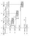
- the entire lighting system is set to the address mode. This is because an address assignment command is generated from the operation unit 23 by an input operation to the operation unit 23 by the user (step S1), and the master communication control unit 22 responds to the address assignment command by the plurality of lighting modules 12 0 to 12 n. Create a command to start address mode for each.
- the created address mode start command is transferred to the communication IF unit 21 and transmitted to each of the lighting modules 12 0 to 12 n via the communication line 13 by the communication IF unit 21 (step S2).
- slot 3 is a command length (number of bytes)
- slot 4 is a command number indicating command contents.
- the command length of slot 3 is 0x01
- the command number of slot 4 is 0x00.
- the format of this unique command is not limited to the address mode start command but is also used in the address assignment command.
- the command length is 0x03, and slots 5 and 6 are used.
- Slot 5 is the upper 8 bits (AD-H) of the DMX address
- slot 6 is the lower 8 bits (AD-L) of the DMX address.
- the commands shown here are commands used in the address mode, and not only command transmission from the lighting control master 11 but also command transmission from the lighting modules 12 0 to 12 n are executed.
- the communication I / F unit 31 receives the address mode start command transmitted from the lighting control master 11.
- the received command is supplied to the slave communication control unit 32.
- the slave communication control unit 32 detects 0x91 in which the command slot 0 indicates a unique command, the operation mode of the lighting module is determined in accordance with the command number 0x00 in the subsequent slot 4. Is set to the address mode (step S3).
- the slave communication control unit 32 turns off the on / off switch 35 in each of the plurality of lighting modules 12 0 to 12 n (step S4).
- the illumination control master 11 is connected to the illumination module 120 only via the communication line 13 so as to be communicable. That is, the illumination module 120 is set as one illumination module.
- the master communication control unit 22 determines the DMX address (step S5).
- the value of the DMX address is determined so as to increase in order at a predetermined timing after the start of the address mode.
- an address assignment command including the determined DMX address is created.
- the address assignment command includes the upper 8 bits (AD-H) of the DMX address in the slot 5, and the lower 8 bits (AD-L) of the DMX address in the slot 6.
- the created address assignment command is transferred to the communication IF unit 21, and is output to the communication line 13 by the communication IF unit 21 (step S6). Since this communication line 13 when being connected only to the lighting module 12 0 of the lighting modules 12 0 ⁇ 12 n, the address assignment command is sent to the lighting module 12 0.
- the determination of the DMX address in step S5 and the transmission of the address assignment command in step S6 correspond to transmission means.
- the communication I / F unit 31 receives the address assignment command transmitted from the lighting control master 11.
- the received command is supplied to the slave communication control unit 32.
- the slave communication control unit 32 confirms that the command is an address assignment command according to the slot 0 to slot 4 of the supplied command, the slave communication control unit 32 starts from the slot 5 and the slot 6.
- the DMX address is stored in a memory, for example.
- step S8 By turning on the switch 35 of the lighting module 12 0 in step S8, the lighting control master 11 is communicatively connected via the lighting module 12 0, 12 1 only to the communication line 13.
- the slave communication control unit 32 By the end of the address mode of step S9, the slave communication control unit 32 also receives the lighting module 12 0 in the address assignment command to ignore it. Note that the extraction of the address from the address assignment command in step S7 corresponds to an acquisition unit.
- step S10 After the operation of steps S7 ⁇ S9 of the lighting module 12 0 is completed, the lighting control master 11, master communication control unit 22 determines the next DMX address (step S10). Time from master communication controller 22 transmits an address assignment command at step S6 in step S10 to the start of the determination of the next DMX address is larger than the total operation time of the step S7 ⁇ S9 lighting modules 12 0 .
- step S10 The address assignment command created in step S10 is transferred to the communication IF unit 21 and output to the communication line 13 by the communication IF unit 21 (step S11).
- the communication line 13 from the lighting control master 11 is connected only to the lighting module 12 0, 12 1 of the lighting modules 12 0 ⁇ 12 n, the address assignment command sent to the lighting module 12 0, 12 1 Is done.
- the address assignment command is ignored.
- the communication I / F unit 31 receives the address assignment command transmitted from the illumination control master 11.
- the received command is supplied to the slave communication control unit 32.
- the slave communication control unit 32 confirms that the command is an address assignment command according to the slot 0 to slot 4 of the supplied command, the slave communication control unit 32 starts from the slot 5 and the slot 6.
- the switch 35 is turned on (step S13), and then ends the address mode of the lighting module 12 1 (step S14).
- steps S12 ⁇ S14 are the same as the operation of steps S7 ⁇ S9 in the illumination module 12 0.
- the address assignment command is transmitted from the lighting control master 11 in that order, and the same operations as in steps S7 to S9 are performed.
- the master communication control unit 22 repeatedly determines the DMX address repeatedly to the maximum value that can be set at the above-described predetermined timing. The number of times the DMX address is determined is equal to or more than the number n + 1 of the lighting modules 12 0 to 12 n . Then, the master communication control unit 22 determines the maximum value of the DMX address (step S21), and outputs it to the communication line 13 by the communication IF unit 21 (step S22), thereby ending the operation in the address mode (step S22). S23).
- the master communication control unit 22 determines the maximum DMX address that can be set for the lighting module 12 n and communicates it with the communication IF unit 21. When outputting to the line 13, the operation in the address mode may be terminated.
- the operation mode is the lighting control mode. Normally in the lighting control mode, commands are only sent from the lighting control master 11 to the lighting modules 12 0 to 12 n .
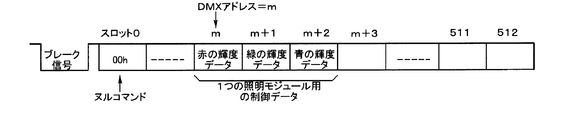
- the luminance of RGB is indicated by 1 byte for each, 3 bytes in total. Therefore, three slots of the DMX command, which is a light emission control command, are used for storing control data of one lighting module.
- the slot m is red luminance data
- the slot m + 1 is green luminance data
- the slot m + 2 is blue luminance data
- the DMX address is the slot m which is the head position of the three slots. Instruct.
- the master communication control unit 22 performs a plurality of illuminations according to the toning command.
- a DMX command including RGB toning data for each of the modules 12 0 to 12 n , that is, each DMX address is created.
- This DMX command has the data format shown in FIG.
- the DMX command is transmitted to each of the lighting modules 12 0 to 12 n through the communication line 13 by the communication IF unit 21.
- the communication I / F unit 31 receives the DMX command transmitted from the lighting control master 11.
- the received DMX command is supplied to the slave communication control unit 32.
- the slave communication control unit 32 detects that the slot 0 of the DMX command indicates a null command, the slave DMX command is set in steps S7, S12, etc.
- the data of three consecutive slots from the slot of the DMX command corresponding to the DMX address is extracted as red luminance data, green luminance data, and blue luminance data (corresponding to means for extracting control data).
- the luminance data of RGB red green blue
- the light emission control unit 33 supplies a drive current having a value corresponding to the red luminance data between the transparent electrode 41 and the metal electrode 46 (R) of the surface light source 34, so that the transparent electrode 41 and the metal electrode 46 (G) A drive current having a value corresponding to green luminance data is supplied between them, and a drive current having a value corresponding to blue luminance data is supplied between the transparent electrode 41 and the metal electrode 46 (B).
- the emission color of the surface light source 34 is adjusted by supplying a driving current to these surface light sources 34.
- the illumination modules 12 0 ⁇ 12 n on-off switch 35 to each provided since the illumination modules 12 0 ⁇ 12 n respectively mounted such as a ceiling or wall, lighting module 12 A DMX address can be easily assigned to each of 0 to 12 n .
- the DMX addresses are set in the order in which the lighting modules 12 0 to 12 n are connected in the daisy chain, the relationship between the DMX address and each of the lighting modules 12 0 to 12 n can be clarified.
- the DMX address can be easily given again.
- the lighting control master 11 sets an address in the lighting module in the lighting system that controls the plurality of lighting modules 12 0 to 12 n using the DMX512-A standard.
- the present invention can be applied to an illumination system using a standard other than the standard of DMX512-A in order to set an address in the illumination module.
- the address represents the slot number of the DMX command, but the present invention is not limited to this.
- an organic EL element is used as a surface light source in the illumination module, but a light emitting element such as an LED (light emitting diode) other than the organic EL element may be used.
Landscapes
- Circuit Arrangement For Electric Light Sources In General (AREA)
Abstract
Description
120~12n,12k,12end 照明モジュール
13 通信線
21,31 通信I/F部
22 マスタ通信制御部
23 操作部
32 スレーブ通信制御部
33 発光制御部
34 面光源
35 オンオフスイッチ
41 透明電極
42 バンク
43 ホール注入層
44(R),44(G),44(B) 発光層
45 電子注入層
46(R),46(G),46(B) 金属電極
Claims (8)
- 面光源と、マスタ装置から送信された発光制御コマンドを通信線を介して受信し、受信した前記発光制御コマンドに含まれる自身用の制御データに応じて前記面光源を駆動制御する駆動制御部とを備える照明モジュールであって、
前記通信線に接続されるべきオンオフスイッチを含み、
前記オンオフスイッチは前記面光源及び前記駆動制御部と一体に結合していることを特徴とする照明モジュール。 - 前記照明モジュールは他の照明モジュールと共に前記マスタ装置に対して前記通信線によりデイジーチェーン接続され、
前記オンオフスイッチは前記マスタ装置からの前記通信線の上流側と下流側との間に挿入されるべきであることを特徴とする請求項1記載の照明モジュール。 - 前記駆動制御部は、前記マスタ装置から送信されるアドレス付与コマンドを受信して前記アドレス付与コマンドに含まれるアドレスを取得する取得手段と、
前記取得手段によって取得されたアドレスに対応して前記発光制御コマンド内から前記自身用の制御データを取り出す手段と、を有することを特徴とする請求項2記載の照明モジュール。 - 前記オンオフスイッチは、前記取得手段によってアドレスが取得されるまではオフとされ、その後、オンとされることを特徴とする請求項3記載の照明モジュール。
- 前記発光制御コマンドはスロット列を有するシリアル通信コマンドであり、
前記アドレスは前記スロット列中の1つのスロットを指定するアドレスであることを特徴とする請求項4記載の照明モジュール。 - 前記駆動制御部は、前記マスタ装置から送信されるアドレスモード開始コマンドの受信に応じて動作モードをアドレスモードにして前記オンオフスイッチをオフせしめることを特徴とする請求項5記載の照明モジュール。
- 前記駆動制御部は、前記アドレスを取得すると前記アドレスモードを終了することを特徴とする請求項6記載の照明モジュール。
- 発光制御コマンドを送信するマスタ装置と、
各々が面光源を有し、前記マスタ装置から送信された前記発光制御コマンドを通信線を介して受信し、受信した前記発光制御コマンドに含まれる自身用の制御データに応じて前記面光源を各々が駆動制御する複数の照明モジュールと、を備える照明システムであって、
前記マスタ装置に設けられ、所定のタイミングでアドレスを順次設定し、設定したアドレスを含むアドレス付与コマンドを前記通信線に送出する送信手段と、
前記所定のタイミングに同期して前記複数の照明モジュールのうちから予め定められた順番でコマンド受信可能状態となる1つの照明モジュールを設定するスイッチ手段と、を含み、
前記複数の照明モジュール各々は、前記スイッチ手段によって前記1つの照明モジュールとして設定されたとき前記アドレス付与コマンドを受信して前記アドレス付与コマンドに含まれるアドレスを取得する取得手段と、
前記取得手段によって取得されたアドレスに対応して前記発光制御コマンド内から前記自身用の制御データを取り出す手段と、を有することを特徴とする照明システム。
Priority Applications (3)
| Application Number | Priority Date | Filing Date | Title |
|---|---|---|---|
| US14/416,427 US20150189722A1 (en) | 2012-07-24 | 2012-07-24 | Lighting module having surface light source and lighting system |
| PCT/JP2012/068688 WO2014016903A1 (ja) | 2012-07-24 | 2012-07-24 | 面光源を有する照明モジュール及び照明システム |
| JP2014526639A JPWO2014016903A1 (ja) | 2012-07-24 | 2012-07-24 | 面光源を有する照明モジュール及び照明システム |
Applications Claiming Priority (1)
| Application Number | Priority Date | Filing Date | Title |
|---|---|---|---|
| PCT/JP2012/068688 WO2014016903A1 (ja) | 2012-07-24 | 2012-07-24 | 面光源を有する照明モジュール及び照明システム |
Publications (1)
| Publication Number | Publication Date |
|---|---|
| WO2014016903A1 true WO2014016903A1 (ja) | 2014-01-30 |
Family
ID=49996739
Family Applications (1)
| Application Number | Title | Priority Date | Filing Date |
|---|---|---|---|
| PCT/JP2012/068688 Ceased WO2014016903A1 (ja) | 2012-07-24 | 2012-07-24 | 面光源を有する照明モジュール及び照明システム |
Country Status (3)
| Country | Link |
|---|---|
| US (1) | US20150189722A1 (ja) |
| JP (1) | JPWO2014016903A1 (ja) |
| WO (1) | WO2014016903A1 (ja) |
Cited By (2)
| Publication number | Priority date | Publication date | Assignee | Title |
|---|---|---|---|---|
| CN104735868A (zh) * | 2015-03-06 | 2015-06-24 | 浙江晶日照明科技有限公司 | 一种基于智能设备的地埋灯和灯具智能控制系统 |
| JP2015185451A (ja) * | 2014-03-25 | 2015-10-22 | 東芝ライテック株式会社 | 照明器具及び照明制御システム |
Families Citing this family (2)
| Publication number | Priority date | Publication date | Assignee | Title |
|---|---|---|---|---|
| CN110710330B (zh) * | 2017-06-13 | 2022-11-25 | 昕诺飞控股有限公司 | 针对串联连接设备的自动地址分配装置和方法 |
| US12452981B2 (en) * | 2023-09-05 | 2025-10-21 | PoEWit Technologies, Inc | Control system and method |
Citations (5)
| Publication number | Priority date | Publication date | Assignee | Title |
|---|---|---|---|---|
| JPH1040206A (ja) * | 1996-07-26 | 1998-02-13 | Matsushita Electric Ind Co Ltd | データ通信装置 |
| JP2005517278A (ja) * | 2002-02-06 | 2005-06-09 | カラー・キネティックス・インコーポレーテッド | 制御された発光の方法および装置 |
| JP2007123045A (ja) * | 2005-10-27 | 2007-05-17 | Matsushita Electric Works Ltd | 照明制御システム |
| JP2009503778A (ja) * | 2005-07-27 | 2009-01-29 | コーニンクレッカ フィリップス エレクトロニクス エヌ ヴィ | 複数の光源を制御するための照明システム及び方法 |
| JP2011508401A (ja) * | 2007-12-31 | 2011-03-10 | コーニンクレッカ フィリップス エレクトロニクス エヌ ヴィ | 照明効果若しくは照明ショーのデザイン、選択及び/又はカスタム化を促進するための方法並びに装置 |
-
2012
- 2012-07-24 JP JP2014526639A patent/JPWO2014016903A1/ja active Pending
- 2012-07-24 US US14/416,427 patent/US20150189722A1/en not_active Abandoned
- 2012-07-24 WO PCT/JP2012/068688 patent/WO2014016903A1/ja not_active Ceased
Patent Citations (5)
| Publication number | Priority date | Publication date | Assignee | Title |
|---|---|---|---|---|
| JPH1040206A (ja) * | 1996-07-26 | 1998-02-13 | Matsushita Electric Ind Co Ltd | データ通信装置 |
| JP2005517278A (ja) * | 2002-02-06 | 2005-06-09 | カラー・キネティックス・インコーポレーテッド | 制御された発光の方法および装置 |
| JP2009503778A (ja) * | 2005-07-27 | 2009-01-29 | コーニンクレッカ フィリップス エレクトロニクス エヌ ヴィ | 複数の光源を制御するための照明システム及び方法 |
| JP2007123045A (ja) * | 2005-10-27 | 2007-05-17 | Matsushita Electric Works Ltd | 照明制御システム |
| JP2011508401A (ja) * | 2007-12-31 | 2011-03-10 | コーニンクレッカ フィリップス エレクトロニクス エヌ ヴィ | 照明効果若しくは照明ショーのデザイン、選択及び/又はカスタム化を促進するための方法並びに装置 |
Cited By (2)
| Publication number | Priority date | Publication date | Assignee | Title |
|---|---|---|---|---|
| JP2015185451A (ja) * | 2014-03-25 | 2015-10-22 | 東芝ライテック株式会社 | 照明器具及び照明制御システム |
| CN104735868A (zh) * | 2015-03-06 | 2015-06-24 | 浙江晶日照明科技有限公司 | 一种基于智能设备的地埋灯和灯具智能控制系统 |
Also Published As
| Publication number | Publication date |
|---|---|
| US20150189722A1 (en) | 2015-07-02 |
| JPWO2014016903A1 (ja) | 2016-07-07 |
Similar Documents
| Publication | Publication Date | Title |
|---|---|---|
| JP5833759B2 (ja) | 面光源を有する照明モジュール及び照明システム | |
| EP1393599B1 (en) | Methods and apparatus for controlling devices in a networked lighting system | |
| US6777891B2 (en) | Methods and apparatus for controlling devices in a networked lighting system | |
| CN101233790B (zh) | 照明系统和用于控制多个光源的方法 | |
| CN102301826B (zh) | 驱动装置、用于向驱动装置分配地址的方法及照明系统 | |
| US20100176742A1 (en) | Illumination Apparatus and Driving Method Thereof | |
| EP3165055B1 (en) | Splittable light strings and methods of splitting light strings | |
| US11029013B2 (en) | Combined lamp and illumination system | |
| WO2014016903A1 (ja) | 面光源を有する照明モジュール及び照明システム | |
| CN107990221A (zh) | 一种组合灯具及照明系统 | |
| CN101737654A (zh) | 照明设备 | |
| US8996733B2 (en) | Allocation of an operating address to a bus-compatible operating device for luminous means | |
| US9392659B2 (en) | Light-emitting device | |
| EP2656694B1 (en) | Address initialization of lighting device units | |
| CN101779076A (zh) | 用于至少一个发光二极管的发光装置以及为其产生无线电信号的发射器 | |
| KR100513144B1 (ko) | 발광다이오드의 풀칼라 조명 제어시스템 및 제어방법 | |
| US20100176731A1 (en) | Adaptor and Illumination Apparatus | |
| KR20100052985A (ko) | 조명 장치 및 그 구동방법 | |
| CN207762689U (zh) | 一种组合灯具及照明系统 | |
| KR100944943B1 (ko) | 발광 다이오드 조명장치 및 그 제어 방법 | |
| JP2016015346A (ja) | 照明システム | |
| EP2656695B9 (en) | A networked lighting device employing either broadcast or unicast messaging | |
| CN204168549U (zh) | 固态光源模块及固态照明系统 | |
| KR20090104724A (ko) | 조명 기구의 급전 장치 |
Legal Events
| Date | Code | Title | Description |
|---|---|---|---|
| 121 | Ep: the epo has been informed by wipo that ep was designated in this application |
Ref document number: 12881617 Country of ref document: EP Kind code of ref document: A1 |
|
| ENP | Entry into the national phase |
Ref document number: 2014526639 Country of ref document: JP Kind code of ref document: A |
|
| WWE | Wipo information: entry into national phase |
Ref document number: 14416427 Country of ref document: US |
|
| NENP | Non-entry into the national phase |
Ref country code: DE |
|
| 122 | Ep: pct application non-entry in european phase |
Ref document number: 12881617 Country of ref document: EP Kind code of ref document: A1 |