WO2014013720A1 - 構造化照明顕微鏡装置 - Google Patents
構造化照明顕微鏡装置 Download PDFInfo
- Publication number
- WO2014013720A1 WO2014013720A1 PCT/JP2013/004338 JP2013004338W WO2014013720A1 WO 2014013720 A1 WO2014013720 A1 WO 2014013720A1 JP 2013004338 W JP2013004338 W JP 2013004338W WO 2014013720 A1 WO2014013720 A1 WO 2014013720A1
- Authority
- WO
- WIPO (PCT)
- Prior art keywords
- modulated
- image
- observation
- specimen
- wave
- Prior art date
- Legal status (The legal status is an assumption and is not a legal conclusion. Google has not performed a legal analysis and makes no representation as to the accuracy of the status listed.)
- Ceased
Links
Images










Classifications
-
- G—PHYSICS
- G02—OPTICS
- G02B—OPTICAL ELEMENTS, SYSTEMS OR APPARATUS
- G02B21/00—Microscopes
- G02B21/06—Means for illuminating specimens
-
- G—PHYSICS
- G02—OPTICS
- G02B—OPTICAL ELEMENTS, SYSTEMS OR APPARATUS
- G02B21/00—Microscopes
- G02B21/36—Microscopes arranged for photographic purposes or projection purposes or digital imaging or video purposes including associated control and data processing arrangements
- G02B21/365—Control or image processing arrangements for digital or video microscopes
- G02B21/367—Control or image processing arrangements for digital or video microscopes providing an output produced by processing a plurality of individual source images, e.g. image tiling, montage, composite images, depth sectioning, image comparison
-
- G—PHYSICS
- G02—OPTICS
- G02B—OPTICAL ELEMENTS, SYSTEMS OR APPARATUS
- G02B27/00—Optical systems or apparatus not provided for by any of the groups G02B1/00 - G02B26/00, G02B30/00
- G02B27/58—Optics for apodization or superresolution; Optical synthetic aperture systems
Definitions
- the present invention relates to a structured illumination microscope apparatus.
- an object to be observed is illuminated with spatially modulated illumination light, and high spatial frequency information exceeding the resolution limit included in the structure of the object to be observed is contributed to the imaging of the microscope optical system.
- the phase of the spatial illumination is switched, and a plurality of modulated image data (hereinafter, referred to as “modulated images”) obtained under different phases are subjected to an operation, whereby demodulated image data (hereinafter, “ “Demodulated image” or "super-resolution image”).
- an object of the present invention is to improve the efficiency of demodulation operation for acquiring a super-resolution image (demodulated image) from a modulated image.
- An example of the structured illumination microscope apparatus of the present invention includes an illumination optical system that spatially modulates a specimen with stripes, and an imaging that forms a modulated image of the specimen by imaging an observation light beam from the spatially modulated specimen.
- An optical system an acquisition unit that controls at least one of the wave vector of the fringes and the phase of the fringes, acquires the modulation image of the sample by capturing the modulation image, and the modulation image acquired by the acquisition unit And calculating means for generating an image of the sample based on the at least two modulated images having the same wave vector and different phases, and the calculating means In the spatial frequency spectrum of each of the at least two modulated images acquired by the means, at least 4 relating to any two observation points shifted from each other by the wave vector Based on the observations, separated from one another zero-order modulation component and ⁇ 1-order modulation component of the observation light beam superimposed on the two observation points.
- An example of the structured illumination microscope apparatus forms an modulated image of the specimen by forming an illumination optical system that spatially modulates the specimen with stripes and an observation light beam from the spatially modulated specimen.
- the imaging optical system, and at least one of the fringe wave vector and the fringe phase are controlled, an acquisition unit that captures the modulation image and acquires the modulation image of the sample, and the acquisition unit that acquires the modulation image Computing means for generating an image of the sample based on a modulated image, wherein the obtaining means obtains one modulated image with each of two wave number vectors among the three wave number vectors in a closed relationship with each other Then, at least two of the modulation images having different phases are acquired using another one wave vector, and the calculation unit is configured to obtain an empty space for each of the at least four modulation images acquired by the acquisition unit.
- the zero-order modulation component of the observation light beam superimposed on the three observation points and
- the acquisition unit may set the phase difference between at least two modulated images having different phases to ⁇ .
- An example of the structured illumination microscope apparatus forms an modulated image of the specimen by forming an illumination optical system that spatially modulates the specimen with stripes and an observation light beam from the spatially modulated specimen.
- the imaging optical system, and at least one of the fringe wave vector and the fringe phase are controlled, an acquisition unit that captures the modulation image and acquires the modulation image of the sample, and the acquisition unit that acquires the modulation image Computing means for generating an image of the specimen based on a modulated image, wherein the obtaining means obtains one modulated image with each of the three wave vector in a closed relationship and one unmodulated An image is acquired, and the calculation means is an amount of the three wave vectors in the spatial frequency spectrum of each of the three modulated images and one unmodulated image acquired by the acquisition means. Based on the observed value of 12 for any of the three observation points displaced from one another, separated from one another zero-order modulation component and ⁇ 1-order modulation component of the observation light beam superimposed on the three observation points. *
- An example of the structured illumination microscope apparatus forms an modulated image of the specimen by forming an illumination optical system that spatially modulates the specimen with stripes and an observation light beam from the spatially modulated specimen.
- the imaging optical system, and at least one of the fringe wave vector and the fringe phase are controlled, an acquisition unit that captures the modulation image and acquires the modulation image of the sample, and the acquisition unit that acquires the modulation image Computing means for generating an image of the specimen based on a modulated image, wherein the obtaining means is the fringes having the three wave vector in a closed relationship at the same time, and the four modulated images having different phases.
- the arithmetic means obtains any three of the spatial frequency spectra of the four modulated images obtained by the obtaining means that are shifted from each other by the amount of the three wave vectors. Based on the observed value of 12 related stations, separated from each other zero-order modulation component and ⁇ 1-order modulation component of the observation light beam superimposed on the three observation points.
- an example of the structured illumination microscope apparatus of the present invention forms a modulated image of the specimen by imaging an illumination optical system that spatially modulates the specimen with stripes and an observation light beam from the spatially modulated specimen.
- An imaging optical system that controls, at least one of the wave number vector of the fringes and the phase of the fringes, an acquisition unit that captures the modulation image and acquires the modulation image of the sample, and the acquisition unit Computing means for generating an image of the sample based on the modulated image, the obtaining means obtains the three modulated images having the same wave vector and different phases, and the computing means comprises: In the spatial frequency spectrum of each of the three modulation images acquired by the acquisition means, based on six observation values relating to any two observation points shifted from each other by the wave vector. The 0-order modulated component of said observation light beam superimposed on the two observation points, separated from one another a ⁇ 1-order modulation component and ⁇ 2-order modulation components.
- the acquisition unit may set the phase difference between the three modulated images to 2 ⁇ / 3.
- the acquisition means acquires the three modulated images having different phases with each of the three wave number vectors having different directions, and the calculation means performs the separation for each of the three wave number vectors. Also good.
- an example of the structured illumination microscope apparatus of the present invention forms a modulated image of the specimen by imaging an illumination optical system that spatially modulates the specimen with stripes and an observation light beam from the spatially modulated specimen.
- An imaging optical system that controls, at least one of the wave number vector of the fringes and the phase of the fringes, an acquisition unit that captures the modulation image and acquires the modulation image of the sample, and the acquisition unit Calculating means for generating an image of the sample based on a modulated image, and the acquiring means acquires the two modulated images having different phases with each of the three wave number vectors in a closed relationship, One unmodulated image is acquired, and the calculation means includes the three waves in the spatial frequency spectrum of each of the six modulated images and one unmodulated image acquired by the acquisition means.
- the ⁇ first-order modulation components of the observation light beam superimposed on the three observation points are separated from each other, and the three wave vector
- the zero-order modulation component and the ⁇ second-order modulation component of the observation light beam superimposed on the three observation points are separated from each other based on 21 observation values regarding any three observation points that are shifted from each other by twice .
- the acquisition unit may set the phase difference between the two modulated images acquired with at least one wave vector to ⁇ .
- an example of the structured illumination microscope apparatus of the present invention forms a modulated image of the specimen by imaging an illumination optical system that spatially modulates the specimen with stripes and an observation light beam from the spatially modulated specimen.
- An imaging optical system that controls, at least one of the wave number vector of the fringes and the phase of the fringes, an acquisition unit that captures the modulation image and acquires the modulation image of the sample, and the acquisition unit Calculating means for generating an image of the sample based on a modulated image, wherein the acquiring means acquires the four modulated images having different phases from each of the three wave number vectors in a closed relationship with each other, and
- the means In the spatial frequency spectrum of each of the 12 modulation images acquired by the acquisition unit, the means relates to 36 observation points regarding any three observation points that are shifted from each other by the three wave number vectors.
- the ⁇ first-order modulation components of the observation light beam superimposed on the three observation points are separated from each other, and 36 related to any three observation points shifted from each other by twice the three wave number vectors. Based on the observed value, the zero-order modulation component and the ⁇ second-order modulation component of the observation light beam superimposed on the three observation points are separated from each other.
- an example of the structured illumination microscope apparatus of the present invention forms a modulated image of the specimen by imaging an illumination optical system that spatially modulates the specimen with stripes and an observation light beam from the spatially modulated specimen.
- An imaging optical system that controls, at least one of the wave number vector of the fringes and the phase of the fringes, an acquisition unit that captures the modulation image and acquires the modulation image of the sample, and the acquisition unit Computing means for generating an image of the sample based on a modulated image, and the obtaining means includes two of the three wave number vectors in a closed relationship with each other, and each of two wave number vectors having different phases.
- a modulation image is acquired, and the four modulation images having different phases with another one wave vector are acquired, and the calculation means is configured to obtain a spatial frequency of each of the eight modulation images acquired by the acquisition means.
- the ⁇ first-order modulation components of the observation light beams superimposed on the three observation points are mutually converted.
- the zero-order modulation component of the observation light beam superimposed on the three observation points and ⁇ Secondary modulation components are separated from each other.
- the acquisition unit may set the phase difference between the four modulated images having different phases to ⁇ / 2.
- the three wave number vectors may be vectors having the same magnitude and having directions shifted by 120 °.
- FIG. 4 is a diagram for explaining a function of a light beam selector 18. It is a figure explaining the rotation mechanism 18A of the light beam selection part 18.
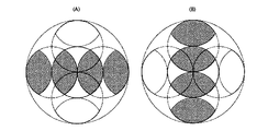
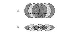
- Equation 1.27 in Section 1.4 (A) is an illustration of Equation 1.27 in Section 1.4, and (B) is an illustration of a modified version of Equation 1.27.
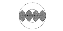
- This is a restoration area according to the first example in section 1.5.
- This is a restoration area according to the second example in Section 1.5.
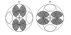
- It is an illustration of Equation 1.33 in Section 1.6.
- This is the area restored in section 1.6.
- It is a figure explaining the expression 1.33 of Section 1.6 in detail.
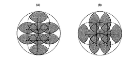
- This is an illustration of Equation 1.63 in Section 1.9. 3 and the lattice structure of the direction the interference fringe is a diagram showing the relationship between the basic vector a 1, a 2 of the grating. It is a figure which shows the relationship of the interference fringe intensity
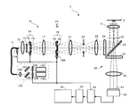
- FIG. 1 is a configuration diagram of the structured illumination microscope apparatus 1.
- the structured illumination microscope apparatus 1 includes a laser unit 100, an optical fiber 11, an illumination optical system 10, an imaging optical system 30, an imaging element 42, a control device 43, an image storage / An arithmetic device 44 and an image display device 45 are provided.
- the illumination optical system 10 is an epi-illumination type, and the sample 2 is illuminated using the objective lens 31 and the dichroic mirror 33 of the imaging optical system 30.
- the laser unit 100 includes a first laser light source 101, a second laser light source 102, shutters 103 and 104, a mirror 105, a dichroic mirror 106, and a lens 107.
- Each of the first laser light source 101 and the second laser light source 102 is a coherent light source, and the emission wavelengths thereof are different from each other.
- the wavelength ⁇ 1 of the first laser light source 101 is longer than the wavelength ⁇ 2 of the second laser light source 102 ( ⁇ 1> ⁇ 2).
- the first laser light source 101, the second laser light source 102, and the shutters 103 and 104 are driven by the control device 43, respectively.
- the optical fiber 11 is composed of, for example, a polarization-preserving single mode fiber in order to guide the laser light emitted from the laser unit 100.
- the position of the output end of the optical fiber 11 in the optical axis direction can be adjusted by the position adjusting mechanism 11A.
- This position adjustment mechanism 11 ⁇ / b> A is driven by the control device 43.
- the illumination optical system 10 includes, in order from the emission end side of the optical fiber 11, a collector lens 12, a polarizing plate 13, a light beam branching unit 14, a condensing lens 17, a light beam selecting unit 18, a lens 21, and a field of view.
- a diaphragm 22, a field lens 23, an excitation filter 24, a dichroic mirror 33, and an objective lens 31 are disposed.
- the light beam branching unit 14 includes a translation mechanism 15 and a diffractive optical element (diffraction grating) 16.
- the light beam selection unit 18 includes a half-wave plate 19, a light beam selection member 20, and a rotation mechanism 18A. And are provided. Each of the beam splitter 14 and the beam selector 18 is driven by the control device 43.
- an objective lens 31 In the imaging optical system 30, an objective lens 31, a dichroic mirror 33, an absorption filter 34, and a second objective lens 35 are arranged in this order from the sample 2 side.
- Specimen 2 is, for example, a culture solution dropped on a parallel plate-like glass surface, and fluorescent cells exist in the vicinity of the glass interface in the culture solution. In this cell, both the first fluorescent region excited by light of wavelength ⁇ 1 and the second fluorescent region excited by light of wavelength ⁇ 2 are expressed.
- the image sensor 42 is a two-dimensional image sensor composed of a CCD, a CMOS, or the like.
- the image sensor 42 captures an image formed on the imaging surface 41 and generates an image. This image is taken into the image storage / arithmetic unit 44 via the control unit 43.
- the control device 43 drives and controls the laser unit 100, the position adjustment mechanism 11A, the light beam branching unit 14, the light beam selecting unit 18, and the image sensor 42.
- the image storage / arithmetic unit 44 performs a calculation on the image given through the control unit 43, stores the calculated image in an internal memory (not shown), and sends it to the image display unit 45.
- the laser light having a wavelength ⁇ 1 (first laser light) emitted from the first laser light source 101 is incident on the mirror 105 via the shutter 103, it reflects off the mirror 105 and enters the dichroic mirror 106.
- the laser light having the wavelength ⁇ 2 (second laser light) emitted from the second laser light source 102 enters the beam splitter 106 via the shutter 104 and is integrated with the first laser light.
- the first laser beam and the second laser beam emitted from the dichroic mirror 106 enter the incident end of the optical fiber 11 through the lens 107.
- the laser light incident on the incident end of the optical fiber 11 propagates inside the optical fiber 11 to generate a point light source at the output end of the optical fiber 11.
- the laser light emitted from the point light source is converted into a parallel light beam by the collector lens 12 and is incident on the diffraction grating 16 of the light beam branching section 14 via the polarizing plate 13 and is branched into diffracted light beams of respective orders.
- the diffracted light beams of these orders are condensed at different positions on the pupil conjugate plane 25 by the condenser lens 17.
- the pupil conjugate plane 25 is the focal position (rear focal position) of the lens 17, and the lens 23 and the lens 21 are arranged with respect to the pupil 32 of the objective lens 31 (the position where the ⁇ first-order diffracted light is condensed).
- the concept of “conjugate position” is determined by a person skilled in the art in consideration of design-related matters such as aberration and vignetting of the objective lens 17 and the lenses 21 and 23. The position was also included.
- the polarizing plate 13 can be omitted, but it is effective for reliably cutting off the excess polarization component. Further, in order to increase the utilization efficiency of the laser light, it is desirable that the axis of the polarizing plate 13 coincides with the polarization direction of the laser light emitted from the optical fiber 11.
- the diffracted light beams of respective orders toward the pupil conjugate plane 25 are incident on the light beam selector 18 disposed in the vicinity of the pupil conjugate plane 25.
- the light beam selection unit 18 selectively passes only one pair of diffracted light beams (here, only ⁇ 1st order diffracted light beams) among the incident diffracted light beams of each order.
- the ⁇ 1st-order diffracted light beam that has passed through the light beam selector 18 is converted into parallel light by the field lens 23 after forming a plane conjugate with the diffraction grating 16 near the field stop 22 by the lens 21, and further passes through the excitation filter 24.
- Each of the ⁇ first-order diffracted light beams collected on the pupil surface 32 becomes a parallel light beam when emitted from the tip of the objective lens 31 and overlaps with each other on the surface of the sample 2 to form interference fringes.
- This interference fringe is used as structured illumination light.
- the modulated image is imaged by the image sensor 42 and taken into the image storage / arithmetic unit 44 via the control unit 43. Further, the captured modulated image is subjected to demodulation calculation (details will be described later) in the image storage / arithmetic unit 44 to generate a demodulated image (super-resolution image).
- the super-resolution image is stored in an internal memory (not shown) of the image storage / arithmetic unit 44 and is sent to the image display unit 45.
- FIG. 2 is a diagram for explaining the light beam branching portion 14
- FIG. 2A is a view of the diffraction grating 16 of the light beam branching portion 14 as seen from the optical axis direction
- FIG. 2B is ⁇ 1 It is a figure which shows the positional relationship of the condensing point which a next diffracted light beam forms in a pupil conjugate plane.
- 2A is a schematic diagram, the structure period of the diffraction grating 16 illustrated in FIG. 2A is not necessarily the same as the actual structure period.
- the diffraction grating 16 is a two-dimensional diffraction grating having a periodic structure in a plurality of different directions perpendicular to the optical axis of the illumination optical system 10.
- the diffraction grating 16 has a periodic structure in each of the first direction V1, the second direction V2, and the third direction V3, which are different by 120 °, and the period (pitch) of these periodic structures is common. Assume.
- the periodic structure of the diffraction grating 16 is either a concentration type periodic structure formed using density (transmittance) or a phase type periodic structure formed using steps (phase difference).
- the phase difference type periodic structure is preferable in that the diffraction efficiency of the + 1st order diffracted light is higher.
- Such parallel light beams incident on the diffraction grating 16 are divided into a first diffracted light beam group branched in the first direction V1, a second diffracted light beam group branched in the second direction V2, and a third light beam branched in the third direction V3. It is converted into a diffracted light beam group.
- the first diffracted light beam group includes a 0th-order diffracted light beam and a ⁇ 1st-order diffracted light beam, and of these, the ⁇ 1st-order diffracted light beams having common orders travel in a symmetric direction with respect to the optical axis.
- the second diffracted light beam group includes a 0th-order diffracted light beam and a ⁇ 1st-order diffracted light beam, and the ⁇ 1st-order diffracted light beam having a common order travels in a symmetric direction with respect to the optical axis. .
- the third diffracted light beam group includes a 0th-order diffracted light beam and a ⁇ 1st-order diffracted light beam, and the ⁇ 1st-order diffracted light beam having a common order travels in a symmetric direction with respect to the optical axis. .
- the ⁇ 1st order diffracted light beam of the first diffracted light beam group, the ⁇ 1st order diffracted light beam of the second diffracted light beam group, and the ⁇ 1st order diffracted light beam of the third diffracted light beam group are brought into the pupil conjugate plane by the condenser lens 17 described above. Are condensed at different positions.
- the condensing points 25d and 25g of the ⁇ first-order diffracted light beams of the first diffracted light beam group are symmetric with respect to the optical axis, and the arrangement direction of the condensing points 25d and 25g is the first. This corresponds to one direction V1.
- the condensing points 25c and 25f of the ⁇ 1st-order diffracted light beams of the second diffracted light beam group are symmetrical with respect to the optical axis, and the arrangement direction of the condensing points 25c and 25f corresponds to the second direction V2.
- the amount of deviation of the condensing points 25c and 25f of the second diffracted light beam group is the same as the amount of deviation of the condensing points 25d and 25g of the first diffracted light beam group.
- the condensing points 25b and 25e of the ⁇ 1st-order diffracted light beams of the third diffracted light beam group are symmetrical with respect to the optical axis, and the arrangement direction of the condensing points 25b and 25e corresponds to the third direction V3. Note that the amount of deviation of the condensing points 25b and 25e of the third light flux group is the same as the amount of deviation of the condensing points 25d and 25g of the first diffracted light flux group.
- the translation mechanism 15 is composed of a piezo motor or the like.
- the translation mechanism 15 is a direction perpendicular to the optical axis of the illumination optical system 10 and is perpendicular to the first direction V1, the second direction V2, and the third direction V3 described above. Is translated.
- the diffraction grating 16 is translated in this direction, the fringe phase of the structured illumination light shifts (details will be described later).
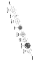
- 3 and 4 are diagrams for explaining the light beam selector 18.
- the half-wave plate 19 of the light beam selection unit 18 sets the polarization direction of the incident diffracted light beam of each order
- the light beam selection member 20 of the light beam selection unit 18 is This is a mask that selectively allows only one group of ⁇ first-order diffracted light beams to pass through among the first to third diffracted light beam groups.
- a rotation mechanism (not shown) of the light beam selection unit 18 rotates the light beam selection member 20 around the optical axis, thereby changing the selected ⁇ first-order diffracted light beam between the first to third diffracted light beam groups.
- the half-wave plate 19 is rotated around the optical axis in conjunction with the light beam selection member 20 to change the polarization direction when the selected ⁇ 1st-order diffracted light beams are incident on the sample 2. Keep polarized.
- the light beam selector 18 switches the stripe direction of the structured illumination light while maintaining the stripe state of the structured illumination light.
- the conditions for maintaining the stripe state will be specifically described.
- the direction of the fast axis (fast axis) of the half-wave plate 19 is ⁇ with respect to the ⁇ 1st-order diffracted light beam branching direction (any one of the first direction V1 to the third direction V3). It is necessary to set the polarization direction of the first-order diffracted light beam to be vertical.
- the fast axis of the half-wave plate 19 is a direction in which the amount of phase delay when light polarized in the direction of the axis passes through the half-wave plate 19 is minimized. It is.
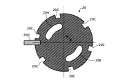
- the opening pattern of the light beam selection member 20 includes a first opening portion 20A and a second opening portion 20B through which one and the other of ⁇ first-order diffracted light beams belonging to the same diffracted light beam group are individually passed.
- the length of each of the first opening 20A and the second opening 20B around the optical axis is set to a length that allows the diffracted light beam linearly polarized in the above-described direction to pass therethrough. Therefore, the shape of each of the first opening 20A and the second opening 20B is a shape close to a partial ring shape.
- first reference position the rotation position of the half-wave plate 19 when the direction of the fast axis of the half-wave plate 19 is parallel to the direction of the axis of the polarizing plate 13
- the amount of rotation of the half-wave plate 19 from the first reference position is controlled to one half of the amount of rotation of the light beam selection member 20 from the second reference position. It should be.
- the rotation amount of the half-wave plate 19 from the first reference position is ⁇ / 2
- the rotation amount of the light beam selection member 20 from the second reference position is set to ⁇ .
- the rotation mechanism 18A of the light beam selection unit 18 selects the first-order diffracted light beam (the branch direction is the first direction V1) of the first diffracted light beam group, as shown in FIG.
- the light beam selection direction of the selection member 20 is rotated rightward from the second reference position by the rotation angle ⁇ 1
- the fast axis direction of the half-wave plate 19 is rotated rightward from the first reference position. Rotate by angle ⁇ 1 / 2.
- the polarization direction of the diffracted light beam of each order before passing through the half-wave plate 19 is parallel to the direction of the axis of the polarizing plate 13 as indicated by a broken line double arrow in FIG.
- the polarization direction of each order diffracted light beam after passing through the half-wave plate 19 is rotated to the right by the rotation angle ⁇ 1
- the polarization direction of the selected ⁇ 1st order diffracted light beam is As indicated by a solid double-pointed arrow in FIG. 4A, the ⁇ first-order diffracted light beams are perpendicular to the branching direction (first direction V1).
- the rotation mechanism 18A of the light beam selector 18 selects the ⁇ first-order diffracted light beam (the branch direction is the second direction V2) of the second diffracted light beam group, as shown in FIG.
- the light beam selection direction of the selection member 20 is rotated rightward from the second reference position by the rotation angle ⁇ 2
- the fast axis direction of the half-wave plate 19 is rotated rightward from the first reference position. Rotate by angle ⁇ 2 / 2.
- the polarization directions of the diffracted light beams of the respective orders before passing through the half-wave plate 19 are parallel to the direction of the axis of the polarizing plate 13 as indicated by the broken line in FIG. 4B.
- the polarization direction of each order of the diffracted light beam after passing through the half-wave plate 19 is rotated to the right by the rotation angle ⁇ 2, so the polarization direction of the selected ⁇ 1st order diffracted light beam is As shown by the solid line double arrow in FIG. 4B, these are perpendicular to the branching direction (second direction V2) of the ⁇ first-order diffracted light beams.
- the rotation mechanism 18A of the light beam selector 18 selects the ⁇ first-order diffracted light beam (the branch direction is the third direction V3) of the third diffracted light beam group, as shown in FIG.
- the light beam selection direction of the selection member 20 is rotated from the second reference position to the left (seen from the sample side; hereinafter the same) by the rotation angle ⁇ 3
- the direction of the fast axis of the half-wave plate 19 is
- the first reference position is rotated to the left by the rotation angle ⁇ 3 / 2.
- the polarization direction of the diffracted light beam of each order before passing through the half-wave plate 19 is parallel to the direction of the axis of the polarizing plate 13 as shown by the broken line in FIG. 4C.
- the polarization directions of the diffracted light beams of the respective orders after passing through the half-wave plate 19 are rotated to the left by the rotation angle ⁇ 3. Therefore, the polarization directions of the selected ⁇ 1st order diffracted light beams are As shown by the actual double-headed arrow in FIG. 4C, these are perpendicular to the branching direction (third direction V3) of the ⁇ first-order diffracted beams.
- the rotation mechanism 18A of the light beam selection unit 18 only needs to interlock the half-wave plate 19 and the light beam selection member 20 with a gear ratio of 2: 1.
- FIG. 5 is a diagram illustrating the function of the light beam selection unit 18 described above.
- a double arrow surrounded by a circular frame indicates the polarization direction of the light beam
- a double arrow surrounded by a square frame indicates the axial direction of the optical element.
- a plurality of (six in the example shown in FIG. 6) notches 20C are formed on the outer peripheral portion of the light flux selecting member 20, and the rotation mechanism 18A includes these notches 20C.
- a timing sensor 20D for detecting the notch 20C is provided.
- the rotation mechanism 18A can detect the rotation position of the light beam selector 18 and thus the rotation position of the half-wave plate 19.
- FIG. 7 is a diagram for explaining the operation of the translation mechanism 15 of the light beam branching section 14.
- the modulated image generated by the structured illumination microscope apparatus 1 includes, in the structure of the sample 2, the 0th order modulation component, the + 1st order modulation component, which is the structure information whose spatial frequency is modulated by the structured illumination light, ⁇ 1
- the next modulation component is superimposed, and the three unknown parameters superimposed on each other need to be made known by demodulation calculation (details will be described later).
- the translation mechanism 15 of the light beam splitting unit 14 is in a direction perpendicular to the optical axis of the illumination optical system 10 as shown in FIG.
- the diffraction grating 16 is shifted in a non-perpendicular direction (x direction) with respect to all of the one direction V1, the second direction V2, and the third direction V3.
- the shift amount L of the diffraction grating 16 necessary for shifting the phase of the interference fringes by a desired shift amount ⁇ is the same as when the light beam selection direction by the light beam selection unit 18 is the first direction V1 and in the second direction V2. And when in the third direction V3 are not necessarily the same.
- the structural period (pitch) of each of the first direction V1, the second direction V2, and the third direction V3 of the diffraction grating 16 is P, and the shift direction (x direction) of the diffraction grating 13 is set.
- the first direction V1 is ⁇ 1
- the angle between the shift direction (x direction) of the diffraction grating 16 and the second direction V2 is ⁇ 2, and the shift direction (x direction) of the diffraction grating 16 and the first direction V1
- a required shift amount L3 of the diffraction grating 16 in the x direction when the selected direction is the third direction V3.
- L3 ⁇ ⁇ P / represented by (4 ⁇ ⁇
- the shift amount L in the x direction of the diffraction grating 16 necessary for setting the phase shift amount of the interference fringes to a desired value ⁇ is the wavelength selection direction (the first direction V1, the second direction V2, and the third direction V3). Any one) and the angle ⁇ formed by the x direction are expressed as shown in Expression (1).
- the shift amount L in the x direction of the diffraction grating 16 necessary for setting the phase shift amount ⁇ of the interference fringes to 2 ⁇ is P / (2 ⁇
- the image storage / arithmetic unit 44 described above is configured by a computer that performs calculations by executing a calculation program, an arithmetic circuit that performs arithmetic processing, or a combination of both.
- the computer may be a general-purpose computer in which a calculation program is installed via a storage medium or a communication network.
- the basic procedure consists of the following four steps.
- Each of a plurality of modulated images is Fourier transformed to generate a plurality of spatial frequency spectra.
- Second step The zero-order modulation component of fluorescence, the first-order modulation component of fluorescence, and the first-order modulation component of fluorescence superimposed on individual spatial frequency spectra are separated from each other in Fourier space.
- the spatial frequency spectrum of the demodulated image is generated by rearranging the zero-order modulation component, the fluorescence first-order modulation component, and the fluorescence first-order modulation component separated from each other in Fourier space. .
- the interference fringes projected onto the sample 2 are two-beam interference fringes (that is, the example in which the structured illumination microscope apparatus 1 is used in the 2D-SIM mode), but the interference fringes projected onto the sample 2 Can be made into a three-beam interference fringe (that is, the structured illumination microscope apparatus 1 is used in the 3D-SIM mode).
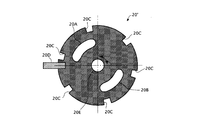
- a light beam selection member 20 'as shown in FIG. 8 is used instead of the light beam selection member 20 shown in FIG.
- This light beam selection member 20 ' is the same as the light beam selection member 20 shown in FIG. 6, but is provided with an opening 20E for passing the 0th-order diffracted light beam.
- the opening 20E is formed in the vicinity of the optical axis, and the shape of the opening 20E is, for example, a circle. According to such a light beam selection member 20 ', not only the ⁇ 1st order diffracted light beam but also the 0th order diffracted light beam can contribute to the interference fringes.
- the interference fringes generated by the interference of the three diffracted light beams are spatially modulated not only in the surface direction of the sample 2 but also in the depth direction of the sample 2. Therefore, according to the interference fringes, a super-resolution effect can be obtained also in the depth direction of the sample 2.
- the contents of the demodulation operation to be executed by the image storage / arithmetic unit 44 are different between the 2D-SIM mode and the 3D-SIM mode. This is because, in the modulation image generated in the 2D-SIM mode, three components of the fluorescence zero-order modulation component, the fluorescence plus first-order modulation component, and the fluorescence minus first-order modulation component are superimposed.
- the modulated image generated in the SIM mode includes 5th order of the 0th order modulation component of fluorescence, the 1st order modulation component of fluorescence, the 1st order modulation component of fluorescence, the + 2nd order modulation component of fluorescence, and the 2nd order modulation component of fluorescence This is because the components are superimposed.
- the number of modulation components to be superimposed on the modulated image is different between the 2D-SIM mode and the 3D-SIM mode, the number of frames of the modulated image to be acquired by the control device 43 is also different. This will be described in detail below.
- interference fringe intensity distribution in the 2D-SIM mode is defined as follows.
- the fluorescence intensity distribution I fl (x) is expressed as follows.
- the modulated image represented in Fourier space (that is, the spatial frequency spectrum of the modulated image) is represented as follows.
- the interference fringe intensity distribution of 2D-SIM is expressed as follows (the fringes have a sinusoidal intensity distribution).
- ⁇ 0 is the spatial frequency (modulation frequency) of the interference fringes.
- ⁇ is a coordinate in Fourier space.
- Equation 1.6 Equation 1.3, and Equation 1.4, it can be seen that the modulated image in the Fourier space is expressed as follows.
- the spatial frequency spectrum in the Fourier space is simply referred to as “spectrum”. Further, the corresponding subscript “ ⁇ i ” is attached to the modulated image acquired when the phase of the interference fringes is ⁇ i .
- Equation 1.7 a fluorescence first-order modulation component, a fluorescence first-order modulation component, and a fluorescence zero-order modulation component.
- Three terms on the right side of Equation 1.7 correspond to each of these modulation components. That is, since the sample (fluorescence) is spatially modulated with stripes having a sinusoidal intensity distribution, the spectrum of the modulation image can be expressed by three modulation components (0th order modulation component and ⁇ 1st order modulation component) of fluorescence. it can.
- the + 1st order modulation component superimposed on the observation point ⁇ is a value (restoration value) that the restoration point ( ⁇ 0 ) should have in the spectrum of the demodulated image
- the ⁇ 1st order modulation component superimposed on the observation point ⁇ is The value (restoration value) that the restoration point ( ⁇ + ⁇ 0 ) in the spectrum of the demodulated image should have
- the zero-order modulation component superimposed on the observation point ⁇ is the value (restoration) that the restoration point ⁇ in the spectrum of the demodulation image should have. Value). This is true for each observation point in the spectrum of the modulated image.
- a large black spot in FIG. 9 corresponds to a certain observation point, and a large black spot and two small black spots on both sides thereof correspond to three restoration points restored from the observation point.
- the spatial frequency (modulation frequency) ⁇ 0 of the fringes in the conventional 2D-SIM is set so that
- ⁇ 2NA is A restoration value of a restoration point that satisfies
- FIG. 10 shows the distribution of the reciprocal of the condition number of the matrix M.
- the first phase phi 1 0 ° of the modulated image Distant
- the phase phi 3 of the phase phi 2 and the third modulated image of the second modulation image as a variable.
- the first-order modulation component of fluorescence superimposed on the observation point ⁇ and the zero-order modulation component of fluorescence superimposed on the observation point ( ⁇ + ⁇ 0 ) are both restored to the restoration point ( ⁇ + ⁇ 0 ).
- the fluorescence first-order modulation component superimposed on the observation point ( ⁇ + ⁇ 0 ) and the fluorescence zero-order modulation component superimposed on the observation point ⁇ both correspond to the restoration value of the restoration point ⁇ . That is, these two observation points ⁇ and ( ⁇ + ⁇ 0 ) include the restoration values of the two common restoration points ⁇ and ( ⁇ + ⁇ 0 ). This relationship is used in the two-image two-point restoration in this section. This will be specifically described below.
- the interference fringe intensity distribution is the same as that of the conventional 2D-SIM, the observation range of the spectrum of the modulated image is represented by
- the spatial frequency (modulation frequency) ⁇ 0 of the stripes in this section is set so that
- the spatial frequency (modulation frequency) ⁇ 0 of the fringes is set by the grating pitch of the diffraction grating 16 (the fringe pitch formed on the specimen).
- observation values of two observation points ⁇ and ( ⁇ + ⁇ 0 ) separated by ⁇ 0 can be obtained from the spectrum of one modulated image.
- the observed value of ( ⁇ + ⁇ 0 ) can be obtained only in a range where ⁇ satisfies
- the observed value at the observation point ⁇ and the observed value at the observation point ( ⁇ + ⁇ 0 ) in the spectrum of one modulated image are expressed by the following equations.
- the restoration values (unknown numbers) of the four restoration points appear on the right side of these expressions 1.12 and 1.13. In order to make these four restoration values known, two more equations are necessary.
- each spectrum of two modulated images having different phases ⁇ is generated, and a total of four observation values relating to two observation points ⁇ and ( ⁇ + ⁇ 0 ) are referred to from each of the two spectra.
- a total of four expressions including four restoration values are obtained.
- ⁇ 1 OTF ( ⁇ )
- ⁇ 2 OTF ( ⁇ + ⁇ 0 )
- the phase ⁇ of the first modulated image is ⁇ 1
- the phase ⁇ of the second modulated image is ⁇ If 2 is set, the four equations are represented by the following matrix.
- the inner circular frame is the outer edge (
- 2NA) of the normal resolution range.
- the outer circular frame is the outer edge (
- 4NA) of the super-resolution range.
- the two large black dots in FIG. 11 indicate two observation points that are shifted by the spatial frequency (modulation frequency) ⁇ 0 of the stripes.
- the two large black dots and the two small black dots in FIG. Four restoration points restored from two observation points are shown.
- the restoration values of the entire filled area in FIG. 11 are obtained by repeating the calculation of the four restoration values while moving the two observation points within the normal resolution range.
- the determinant of the matrix M may take a value other than zero.
- the determinant of the matrix M is expressed as follows.
- phase phi 1 of the first modulated image the phase difference [Delta] [phi between the phase phi 2 of the second modulation image, if only a ⁇ ⁇ 0, detM ⁇ 0, and the equation 1.14 is uniquely Have a good solution.
- the condition necessary for the demodulation operation in section 1.3 is ⁇ ⁇ 0.
- the painted area in FIG. 12A is a recoverable range when ⁇ ⁇ ⁇
- , whereas the filled area in FIG. 12B is a recoverable range when ⁇ ⁇ ( In either case,
- 2NA.)
- the inner circle is the outer edge of the normal resolution range (
- 2NA)
- the outer circle is the outer edge of the super-resolution range (
- 4NA).
- the number of directions of interference fringes is 1. However, if the number of directions of interference fringes is 3, and the same demodulation operation as in section 1.3 is applied to each direction, as shown in FIG. A wide area can be restored.
- Two-pass restoration will be described as a demodulation operation of the 2D-SIM of this embodiment.
- the number of interference fringe directions is set to two.
- each interference fringe is represented by a wave vector.
- the magnitude of this wave vector indicates the magnitude of the spatial frequency of the interference fringes, and the direction of the wave vector indicates the direction of the interference fringes.
- First step Two modulated images having a wave vector of ⁇ 0 and different phases are acquired, and a spectrum of each of the two modulated images is generated. Each of these two modulated images is represented as follows.
- the restoration value of the region shown in FIG. 14A is obtained by performing the same demodulation operation as in section 1.3 on the spectrum of each of the two modulated images.
- Second step Two modulated images having a wave vector of ⁇ 1 and different phases are acquired, and respective spectra of the two modulated images are generated. Each of these two modulated images is represented as follows.
- the restoration value of the region shown in FIG. 14B is obtained by performing the same demodulation operation as in section 1.3 on the spectrum of each of the two modulated images.
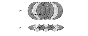
- the first step and the third step can be collectively expressed as shown in FIG. That is, the four black dots connected in the horizontal direction on the horizontal line in FIG. 16B are in Fourier space (wave number space) of four restoration values (unknown numbers) obtained from simultaneous equations equivalent to the expression 1.14 solved in the first step. Represents the position.
- the large black dot at the center is one known number of Fourier spaces (wave number space) obtained from the expression of the first step.
- the small black dots at both ends indicate the positions in the Fourier space (wave number space) of the two restored values (unknown numbers) of the simultaneous equations 1.26 solved in the third step.
- the mutual positional relationship between these eight black spots is the same regardless of which example is selected.
- the range of positions where black spots can be taken in Fourier space (wave number space) is limited by the range of positions where two large black spots (center) can be taken in Fourier space (wave number space). Since the range of positions that can be taken by the two large black dots is
- FIG. 16A shows the second step and the fourth step in the same manner as FIG. 16B.
- two-pass restoration is performed with emphasis on suppressing the number of modulated images (number of spectra). Therefore, in the first example, the number of directions of the wave vector is set to 2, and two modulated images having different phases are obtained for each of two wave vector ⁇ 1 and ⁇ 2 different from each other (a total of four modulated images). An image is acquired) and the spectrum of each of the four modulated images is generated (a total of four spectra are generated).
- the phase difference ⁇ between two modulated images acquired with the same wave vector is set to ⁇ ⁇ ⁇ .
- is set to
- the number of directions of the wave vector is assumed to be 3 (modulated images are acquired from each of the three wave vector ⁇ 1 , ⁇ 2 , ⁇ 3 , and respective spectra of these modulated images are generated).
- the number of phases is 2 (two modulated images I (0) and I (1) having the same fringe direction and different phases. However, in each of the other two directions (wave vector ⁇ 2 , ⁇ 3 ), the number of phases is suppressed to 1 (two modulated images I (2) and I (3) having different fringe directions are obtained. ).
- each wave vector is set to
- FIG. 19 is an illustration of the calculation. However,
- and ⁇ 1 ⁇ ⁇ 2
- the three large black dots in FIG. 19A indicate the three observation points located at the vertices of the triangle drawn by the three wave vector ⁇ 1 , ⁇ 2 , ⁇ 3 in the spectrum of the modulated image.
- Three large black spots and nine small black spots in A) indicate restoration points (a total of 12 restoration points) restored from these three observation points.
- FIG. 19B is an illustration when the same restoration is performed by inverting the direction of the triangle.
- the restoration in FIG. 19A and the restoration in FIG. 19B can be performed in parallel. In this section, these two types of restoration are performed, and the entire filled area shown in FIG. 20 is restored.
- FIG. 20 is a combination of the restoration area shown in FIG. 19A and the restoration area shown in FIG.
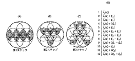
- FIG. 21 is a diagram illustrating the calculation in this section divided into three steps.
- FIG. 21A shows four restoration points 1 to 4 restored in the first step.
- FIG. 21B shows four restoration points 5 to 8 restored in the second step.
- FIG. 21C shows the four restoration points 9 to 12 restored in the third step.
- FIG. 21D shows the correspondence between the numbers 1 to 12 in the figure and the restoration values. .
- First step By applying four observation values regarding two observation points 1 and 2 arranged in the direction of the wave vector ⁇ 1 at an interval
- Second step Using the respective restoration values of the restoration points 1 and 2 , four restoration points 5, 6, 7, and 8 that are shifted from the restoration points 1 and 2 by the wave number vectors ⁇ 2 and ⁇ 3 . Each restoration value is obtained.
- the equations used in this case are two equations (for two phases) relating to the direction of the wave vector ⁇ 1 , one equation relating to the direction of the wave vector ⁇ 2 , one equation relating to the direction of the wave vector ⁇ 3 , There are a total of four equations.
- Third step Using the restoration values of the restoration points 1, 2, 5 respectively, the remaining restoration points 9, 10, which are shifted from the restoration points 1, 2 , 5 by the wave vector ⁇ 2 , ⁇ 3 , The restoration values of 11 and 12 are obtained.
- the formula used in this case the two expressions (observation point 2 min) with respect to the direction of wave vector xi] 2, and two equations for the direction of the wave vector xi] 3 (observation point 2 min), total 4 Is one expression.
- the number of phases in all three directions is limited to 1, and instead, one unmodulated image is acquired and the spectrum of the unmodulated image is generated.
- the spectrum of the unmodulated image is a Fourier transform of the unmodulated image.
- the number of modulated images (the number of modulated image spectra) is 3, and the number of unmodulated images (the number of unmodulated image spectra) is 1, so a total of 12 observations from three observation points. The value is obtained.
- the restoration value of the restoration point is obtained individually.
- the interference fringes projected onto the specimen are the sum of three interference fringes with different directions as follows (three-way interference fringes). A method for projecting the three-way interference fringes will be described later.
- a certain observation point ⁇ in the spectrum of the modulated image has a zero-order modulation component of the fluorescence, a ⁇ first-order modulation component of the fluorescence by the wave vector ⁇ 1 , and a ⁇ first-order modulation component of the fluorescence by the wave vector ⁇ 2. And a total of seven components of the fluorescence ⁇ first-order modulation component by the wave vector ⁇ 3 are superimposed.
- the whole of these three observation points ⁇ , ( ⁇ + ⁇ 1 ), ( ⁇ + ⁇ 2 ) includes the restoration values of 12 restoration points.
- FIG. 22 is an illustration thereof. However,
- and ⁇ 1 ⁇ ⁇ 2
- the three large black dots in FIG. 22A indicate the three observation points located at the vertices of the triangle drawn by the three wave vector ⁇ 1 , ⁇ 2 , ⁇ 3 in the spectrum of the modulated image.
- Three large black spots and nine small black spots in A) indicate restoration points (a total of 12 restoration points) restored from these three observation points.
- FIG. 22B is an illustration when the same restoration is performed by inverting the direction of the triangle.
- the restoration in FIG. 22A and the restoration in FIG. 22B can be performed in parallel. In this section, these two types of restoration are performed, and the same area as the filled area shown in FIG. 20 is restored.
- the phases (consisting of three components) of the three-way interference fringes reflected in each of the four modulated images I (1) , I (2) , I (3) , and I (4 ) are, for example,
- the interference fringe intensity distribution in each of the four modulated images I (1) , I (2) , I (3) , and I (4) is as follows.
- the sum of the interference fringe intensity distributions in the four modulated images is as follows.
- each part of the specimen is illuminated with the same amount of light.
- the patterns of the three-way interference fringes are common, and only the pattern positions are shifted. Therefore, the following relationship holds.
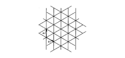
- FIG. 23 is a diagram showing the relationship between the lattice structure of three-way interference fringes and the basic vectors a 1 and a 2 of the lattice.
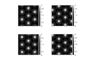
- FIG. 24 is a diagram showing the relationship of the interference fringe intensity distribution among the four modulated images.
- the lattice patterns are moved in parallel so as not to overlap each other between the four modulated images.
- the unit of the movement amount is half of the basic vector of the lattice.
- the diffraction grating 16 (FIG. 2A) described above is formed as in the case of generating other interference fringes (one-way interference fringes). Can be used.
- the aperture pattern of the light beam selection member 20 includes the 0th order diffracted light of each group, the second and higher order diffracted lights of each group, and the + 1st order diffracted light of each group. And is set so as to transmit only the ⁇ 1st order diffracted light of each group.
- the condensing points formed on the pupil plane are only the condensing points by the three ⁇ 1st order diffracted lights.
- FIG. 25A shows the arrangement of the condensing points in the case where excess diffracted light is not cut by the light beam selecting member 20, and FIG. The arrangement
- three condensing points are formed at positions shifted by 120 °.
- Three diffracted lights (here, three ⁇ 1st order diffracted lights) emitted from these three condensing points enter the illumination area of the specimen from three directions, and form three-way interference fringes on the specimen.
- the diffracted light contributing to the interference fringes is three ⁇ 1st order diffracted lights here, it goes without saying that the three + 1st order diffracted lights may be used.
- each of the laser light emitted from the laser light source A, the laser light emitted from the laser light source B, and the laser light emitted from the laser light source C is split into two branched fibers.
- the point light sources a and a ′ are coherent light sources generated from the laser light source A
- the point light sources b and b ′ are coherent light sources generated from the laser light source B
- the point light sources c and c ′ is a coherent light source generated from the laser light source C.
- the six laser lights emitted from these six point light sources are incident on the specimen illumination area from six directions, and form three-way interference fringes on the specimen.
- the laser beams La and La ′ emitted from the point light sources a and a ′, the laser beams Lb and Lb ′ emitted from the point light sources b and b ′, and the laser beams Lc emitted from the point light sources c and c ′, Lc ′ does not interfere with each other. Accordingly, the interference fringes formed on the specimen are a superposition of three types of two-beam interference fringes. Therefore, the super-resolution effect is not lowered and the utilization efficiency of the laser light is high.
- the diffraction grating 16 is translated in order to change the phase of the three-way interference fringe (consisting of three components). Instead of moving, the phase difference between the laser beams La and a ′, the phase difference between the laser beams Lb and Lb ′, and the phase difference between the laser beams Lc and Lc may be changed.
- the interference fringe intensity distribution in the 3D-SIM is assumed as follows.
- the interference fringe intensity distribution K (r) in the 3D-SIM is expressed as follows.
- the interference fringe intensity distribution K is expressed as follows.
- the fringes are first-period fringes having a sinusoidal intensity distribution (interference fringes due to left and right light among the three light beams consisting of the central light and its left and right lights), and a second having a sinusoidal intensity distribution. It consists of a fringe with a cycle (twice the first cycle) (interference fringes due to the center light and the right light (or left light) among the three light beams consisting of the center light and its left and right lights) superimposed.
- the fluorescent intensity distribution of the sample is I 0 (r) K (r). Assuming that it is expressed, the approximation that the fluorescence generated at each point of the sample does not excite the fluorescent substance at other points (Born approximation) is adopted.
- the modulated image I (x, z) acquired in the 3D-SIM mode is expressed as follows.
- the modulated image represented in Fourier space that is, the spatial frequency spectrum of the modulated image
- the modulated image represented in Fourier space that is, the spatial frequency spectrum of the modulated image
- a, b, and c are values determined by the intensity balance of the three light beams ( ⁇ first-order diffracted light and zero-order diffracted light) that contribute to the interference fringes of the 3D-SIM.
- the observation point ⁇ in the spectrum of the modulated image acquired in the 3D-SIM mode has a fluorescence first-order modulation component, a fluorescence first-order modulation component, a fluorescence + second-order modulation component, a fluorescence + second-order modulation component, Five components of the fluorescence zero-order modulation component are superimposed.
- the ⁇ first-order modulation component superimposed on the observation point ⁇ is a value (restoration value) that the restoration point ( ⁇ ⁇ ⁇ 0 ) should have in the spectrum of the demodulated image
- the ⁇ second-order modulation component superimposed on the observation point ⁇ Is the value (restoration value) that the restoration point ( ⁇ ⁇ 2 ⁇ 0 ) in the spectrum of the demodulated image should have, and the zero-order modulation component superimposed on the observation point ⁇ should have the restoration point ⁇ in the spectrum of the demodulation image Value (restoration value).
- the ⁇ first-order modulation component superimposed on the observation point ⁇ is a fringe of the second period (twice the first period) having a sinusoidal intensity distribution (three light fluxes consisting of the central light and its left and right lights).
- the ⁇ secondary modulation component superimposed on the observation point ⁇ has a first period having a sinusoidal intensity distribution. It is a component modulated by fringes (interference fringes due to left and right light out of three light beams composed of central light and left and right light).
- a large black spot in FIG. 27 corresponds to a certain observation point, and a large black spot and four small black spots on both sides thereof correspond to five restoration points restored from the observation point.
- the first-order modulation component of fluorescence superimposed on the observation point ⁇ and the zero-order modulation component of fluorescence superimposed on the observation point ( ⁇ + ⁇ 0 ) are both restored to the restoration point ( ⁇ + ⁇ 0 ).
- the fluorescent second-order modulation component superimposed on the observation point ⁇ and the fluorescent first modulation component superimposed on the observation point ( ⁇ + ⁇ 0 ) both correspond to the restoration value of the restoration point ( ⁇ + 2 ⁇ 0 ).
- the first-order modulation component of the fluorescence superimposed on the observation point ( ⁇ + ⁇ 0 ) and the zero-order modulation component of the fluorescence superimposed on the observation point ⁇ correspond to the restoration value of the restoration point ⁇
- Both the + 2nd order modulation component of the superimposed fluorescence and the 1st order modulation component of the fluorescence superimposed on the observation point ⁇ correspond to a restored value of ( ⁇ 0 ). That is, these two observation points ⁇ and ( ⁇ + ⁇ 0 ) include the restoration values of four common restoration points ( ⁇ 0 ), ⁇ , ( ⁇ + ⁇ 0 ), and ( ⁇ + 2 ⁇ 0 ).
- the observation value at the observation point ⁇ and the observation value at the observation point ( ⁇ + ⁇ 0 ) are expressed by the following equations.
- FIG. 28 is a diagram showing the frequency range of the 3D-SIM demodulated image in this section.
- 28A is an xy cross section
- FIG. 28B is a zx cross section.
- the above explanation is an explanation of restoration related to a certain wave vector (one direction).
- phase difference ⁇ between the three modulated images acquired with the same wave vector is set to 2 ⁇ / 3.
- the number of directions (number of wave vectors) is 3.
- An unmodulated image is represented as I (0) .
- ⁇ 1st order modulation component and the ⁇ 2nd order modulation component are summarized and expressed as follows.
- the zero-order modulation component (normal resolution component) can be expressed as follows.
- Equation 2.42 first, by applying seven observation values related to the observation point ⁇ in each spectrum of seven modulated images to Equation 2.42, the seven restored values on the right side of Equation 2.42, that is, Are restored ( ⁇ first-order modulation component, ⁇ second-order modulation component, and zero-order modulation component), respectively.
- the modulation component and the ⁇ 1st order modulation component can be separated.
- Equation 2.35 the ⁇ 1st order modulation component is obtained from Equation 2.35.
- the zero-order modulation component and the ⁇ first-order modulation component are separated by fitting the observed values of the 12 modulation image spectra (12 spectra) to this equation.
- Section 1.6 described above may be applied to 3D-SIM as follows.
- the number of directions (number of wave vectors) is 3.
- the number of phases is set to 4, but the number of phases in each of the other two directions is suppressed to 2.
- DESCRIPTION OF SYMBOLS 1 ... Structured illumination microscope apparatus, 100 ... Laser unit, 11 ... Optical fiber, 10 ... Illumination optical system, 30 ... Imaging optical system, 42 ... Imaging device, 43 ... Control apparatus, 44 ... Image storage and calculation apparatus, 45 DESCRIPTION OF SYMBOLS ... Image display apparatus, 12 ... Collector lens, 13 ... Polarizing plate, 14 ... Light beam splitting part, 17 ... Condensing lens, 18 ... Light beam selection part, 21 ... Lens, 22 ... Field stop, 23 ... Field lens, 24 ... Excitation Filter, 33 ... Dichroic mirror, 31 ... Objective lens, 34 ... Absorption filter, 35 ... Second objective lens, 2 ... Sample
Landscapes
- Physics & Mathematics (AREA)
- General Physics & Mathematics (AREA)
- Optics & Photonics (AREA)
- Engineering & Computer Science (AREA)
- Multimedia (AREA)
- Chemical & Material Sciences (AREA)
- Analytical Chemistry (AREA)
- Computer Vision & Pattern Recognition (AREA)
- Microscoopes, Condenser (AREA)
Abstract
変調画像から復調画像を取得するための復調演算を効率化するために、本発明の構造化顕微鏡装置の一態様は、縞で標本を空間変調し、前記縞の波数ベクトル及び位相の少なくとも一方を制御すると共に、前記標本の変調像を撮像して変調画像を取得する取得手段と、取得した変調画像に基づいて前記標本の画像を生成する演算手段とを備え、前記取得手段は、前記波数ベクトルが同じであって前記位相が異なる少なくとも2つの前記変調画像を取得し、前記演算手段は、前記取得手段で取得した少なくとも2つの前記変調画像の各々の空間周波数スペクトルにおいて、前記波数ベクトルの分だけ互いにずれた任意の2つの観測点に関する少なくとも4つの観測値に基づいて、前記2つの観測点に重畳された前記観察光束の0次変調成分及び±1次変調成分を互いに分離する。
Description
本発明は、構造化照明顕微鏡装置に関する。
生体標本などの被観察物を超解像観察するための手法に、被観察物の構造の空間周波数を照明光で変調する手法がある(特許文献1を参照)。
この手法では、空間変調された照明光で被観察物を照明し、被観察物の構造に含まれる解像限界を超える高い空間周波数の情報を、顕微鏡光学系の結像に寄与させる。また、空間照明の位相を切り替え、互いに異なる位相の下で得られた複数の変調像のデータ(以下、「変調画像」と称す。)へ演算を施すことにより、復調像のデータ(以下、「復調画像」又は「超解像画像」と称す。)を取得する。
しかし、1枚の超解像画像を観察するためには、複数枚の変調画像を取得し、それら変調画像の各々のスペクトルを生成する必要があるため、高速に観察することが難しい。
そこで本発明は、変調画像から超解像画像(復調画像)を取得するための復調演算を効率化することを目的とする。
本発明の構造化照明顕微鏡装置の一例は、縞で標本を空間変調する照明光学系と、空間変調された前記標本からの観察光束を結像することにより前記標本の変調像を形成する結像光学系と、前記縞の波数ベクトル及び前記縞の位相の少なくとも一方を制御すると共に、前記変調像を撮像して前記標本の変調画像を取得する取得手段と、前記取得手段で取得した前記変調画像に基づいて前記標本の画像を生成する演算手段とを備え、前記取得手段は、前記波数ベクトルが同じであって前記位相が異なる少なくとも2つの前記変調画像を取得し、前記演算手段は、前記取得手段で取得した少なくとも2つの前記変調画像の各々の空間周波数スペクトルにおいて、前記波数ベクトルの分だけ互いにずれた任意の2つの観測点に関する少なくとも4つの観測値に基づいて、前記2つの観測点に重畳された前記観察光束の0次変調成分及び±1次変調成分を互いに分離する。
また、本発明の構造化照明顕微鏡装置の一例は、縞で標本を空間変調する照明光学系と、空間変調された前記標本からの観察光束を結像することにより前記標本の変調像を形成する結像光学系と、前記縞の波数ベクトル及び前記縞の位相の少なくとも一方を制御すると共に、前記変調像を撮像して前記標本の変調画像を取得する取得手段と、前記取得手段で取得した前記変調画像に基づいて前記標本の画像を生成する演算手段とを備え、前記取得手段は、互いに閉じた関係の3つの前記波数ベクトルのうち、2つの波数ベクトルの各々で1つの前記変調画像を取得し、他の1つの波数ベクトルで前記位相の異なる少なくとも2つの前記変調画像を取得し、前記演算手段は、前記取得手段で取得した少なくとも4つの前記変調画像の各々の空間周波数スペクトルにおいて、前記3つの波数ベクトルの分だけ互いにずれた任意の3つの観測点に関する12の観測値に基づいて、前記3つの観測点に重畳された前記観察光束の0次変調成分及び±1次変調成分を互いに分離する。
なお、前記取得手段は、前記位相の異なる少なくとも2つの変調画像間の位相差を、πに設定してもよい。
また、本発明の構造化照明顕微鏡装置の一例は、縞で標本を空間変調する照明光学系と、空間変調された前記標本からの観察光束を結像することにより前記標本の変調像を形成する結像光学系と、前記縞の波数ベクトル及び前記縞の位相の少なくとも一方を制御すると共に、前記変調像を撮像して前記標本の変調画像を取得する取得手段と、前記取得手段で取得した前記変調画像に基づいて前記標本の画像を生成する演算手段とを備え、前記取得手段は、互いに閉じた関係の3つの前記波数ベクトルの各々で1つの前記変調画像を取得すると共に、1つの無変調画像を取得し、前記演算手段は、前記取得手段で取得した3つの前記変調画像及び1つの前記無変調画像の各々の空間周波数スペクトルにおいて、前記3つの波数ベクトルの分だけ互いにずれた任意の3つの観測点に関する12の観測値に基づいて、前記3つの観測点に重畳された前記観察光束の0次変調成分及び±1次変調成分を互いに分離する。
また、本発明の構造化照明顕微鏡装置の一例は、縞で標本を空間変調する照明光学系と、空間変調された前記標本からの観察光束を結像することにより前記標本の変調像を形成する結像光学系と、前記縞の波数ベクトル及び前記縞の位相の少なくとも一方を制御すると共に、前記変調像を撮像して前記標本の変調画像を取得する取得手段と、前記取得手段で取得した前記変調画像に基づいて前記標本の画像を生成する演算手段とを備え、前記取得手段は、互いに閉じた関係の3つの前記波数ベクトルを同時に有した前記縞で、前記位相の異なる4つの前記変調画像を取得し、前記演算手段は、前記取得手段で取得した4つの前記変調画像の各々の空間周波数スペクトルにおいて、前記3つの波数ベクトルの分だけ互いにずれた任意の3つの観測点に関する12の観測値に基づいて、前記3つの観測点に重畳された前記観察光束の0次変調成分及び±1次変調成分を互いに分離する。
また、本発明の構造化照明顕微鏡装置の一例は、縞で前記標本を空間変調する照明光学系と、空間変調された前記標本からの観察光束を結像することにより前記標本の変調像を形成する結像光学系と、前記縞の波数ベクトル及び前記縞の位相の少なくとも一方を制御すると共に、前記変調像を撮像して前記標本の変調画像を取得する取得手段と、前記取得手段で取得した前記変調画像に基づいて前記標本の画像を生成する演算手段とを備え、前記取得手段は、前記波数ベクトルが同じであって前記位相が異なる3つの前記変調画像を取得し、前記演算手段は、前記取得手段で取得した3つの前記変調画像の各々の空間周波数スペクトルにおいて、前記波数ベクトルの分だけ互いにずれた任意の2つの観測点に関する6つの観測値に基づいて、前記2つの観測点に重畳された前記観察光束の0次変調成分、±1次変調成分及び±2次変調成分を互いに分離する。
なお、前記取得手段は、前記3つの変調画像間の位相差を、2π/3に設定してもよい。
また、前記取得手段は、方向の異なる3つの前記波数ベクトルの各々で、前記位相の異なる3つの前記変調画像を取得し、前記演算手段は、前記3つの波数ベクトルの各々について前記分離を行ってもよい。
また、本発明の構造化照明顕微鏡装置の一例は、縞で前記標本を空間変調する照明光学系と、空間変調された前記標本からの観察光束を結像することにより前記標本の変調像を形成する結像光学系と、前記縞の波数ベクトル及び前記縞の位相の少なくとも一方を制御すると共に、前記変調像を撮像して前記標本の変調画像を取得する取得手段と、前記取得手段で取得した変調画像に基づいて前記標本の画像を生成する演算手段とを備え、前記取得手段は、互いに閉じた関係の3つの前記波数ベクトルの各々で前記位相の異なる2つの前記変調画像を取得すると共に、1つの無変調画像を取得し、前記演算手段は、前記取得手段で取得した6つの前記変調画像及び1つの前記無変調画像の各々の空間周波数スペクトルにおいて、前記3つの波数ベクトルの分だけ互いにずれた任意の3つの観測点に関する21の観測値に基づいて、前記3つの観測点に重畳された前記観察光束の±1次変調成分を互いに分離し、前記3つの波数ベクトルの2倍分だけ互いにずれた任意の3つの観測点に関する21の観測値に基づいて、前記3つの観測点に重畳された前記観察光束の0次変調成分及び±2次変調成分を互いに分離する。
なお、前記取得手段は、少なくとも1つの前記波数ベクトルで取得される2つの前記変調画像間の位相差を、πに設定してもよい。
また、本発明の構造化照明顕微鏡装置の一例は、縞で前記標本を空間変調する照明光学系と、空間変調された前記標本からの観察光束を結像することにより前記標本の変調像を形成する結像光学系と、前記縞の波数ベクトル及び前記縞の位相の少なくとも一方を制御すると共に、前記変調像を撮像して前記標本の変調画像を取得する取得手段と、前記取得手段で取得した変調画像に基づいて前記標本の画像を生成する演算手段とを備え、前記取得手段は、互いに閉じた関係の3つの前記波数ベクトルの各々で前記位相の異なる4つの変調画像を取得し、前記演算手段は、前記取得手段で取得した12の前記変調画像の各々の空間周波数スペクトルにおいて、前記3つの波数ベクトルの分だけ互いにずれた任意の3つの観測点に関する36の観測値に基づいて、前記3つの観測点に重畳された前記観察光束の±1次変調成分を互いに分離し、前記3つの波数ベクトルの2倍分だけ互いにずれた任意の3つの観測点に関する36の観測値に基づいて、前記3つの観測点に重畳された前記観察光束の0次変調成分及び±2次変調成分を互いに分離する。
また、本発明の構造化照明顕微鏡装置の一例は、縞で前記標本を空間変調する照明光学系と、空間変調された前記標本からの観察光束を結像することにより前記標本の変調像を形成する結像光学系と、前記縞の波数ベクトル及び前記縞の位相の少なくとも一方を制御すると共に、前記変調像を撮像して前記標本の変調画像を取得する取得手段と、前記取得手段で取得した変調画像に基づいて前記標本の画像を生成する演算手段とを備え、前記取得手段は、互いに閉じた関係の3つの前記波数ベクトルのうち、2つの波数ベクトルの各々で前記位相の異なる2つの前記変調画像を取得し、他の1つの波数ベクトルで前記位相の異なる4つの前記変調画像を取得し、前記演算手段は、前記取得手段が取得した8つの前記変調画像の各々の空間周波数スペクトルにおいて、前記3つの波数ベクトルの分だけ互いにずれた任意の3つの観測点に関する24の観測値に基づいて、前記3つの観測点に重畳された前記観察光束の±1次変調成分を互いに分離し、前記3つの波数ベクトルの2倍分だけ互いにずれた任意の3つの観測点に関する24の観測値に基づいて、前記3つの観測点に重畳された前記観察光束の0次変調成分及び±2次変調成分を互いに分離する。
なお、前記取得手段は、前記位相の異なる4つの変調画像間の位相差を、π/2に設定してもよい。
また、前記3つの波数ベクトルは、大きさが同じであって、方向が120°ずつずれたベクトルであってもよい。
以下、本発明の実施形態として構造化照明顕微鏡装置を説明する。
[装置の説明]
先ず、構造化照明顕微鏡装置の構成を説明する。
先ず、構造化照明顕微鏡装置の構成を説明する。
図1は、構造化照明顕微鏡装置1の構成図である。図1に示すとおり構造化照明顕微鏡装置1には、レーザユニット100と、光ファイバ11と、照明光学系10と、結像光学系30と、撮像素子42と、制御装置43と、画像記憶・演算装置44と、画像表示装置45とが備えられる。なお、照明光学系10は落射型であり、結像光学系30の対物レンズ31及びダイクロイックミラー33を利用して標本2の照明を行う。
レーザユニット100には、第1レーザ光源101、第2レーザ光源102、シャッタ103、104、ミラー105、ダイクロイックミラー106、レンズ107が備えられる。第1レーザ光源101及び第2レーザ光源102の各々は可干渉光源であって、互いの出射波長は異なる。ここでは、第1レーザ光源101の波長λ1は、第2レーザ光源102の波長λ2よりも長いと仮定する(λ1>λ2)。これらの第1レーザ光源101、第2レーザ光源102、シャッタ103、104は、それぞれ制御装置43によって駆動される。
光ファイバ11は、レーザユニット100から射出したレーザ光を導光するために、例えば、偏波面保存型のシングルモードファイバによって構成される。この光ファイバ11の出射端の光軸方向の位置は、位置調節機構11Aによって調節可能である。この位置調整機構11Aは、制御装置43によって駆動される。
照明光学系10には、光ファイバ11の出射端側から順に、コレクタレンズ12と、偏光板13と、光束分岐部14と、集光レンズ17と、光束選択部18と、レンズ21と、視野絞り22と、フィールドレンズ23と、励起フィルタ24と、ダイクロイックミラー33と、対物レンズ31とが配置される。
光束分岐部14には、並進機構15と、回折光学素子(回折格子)16とが備えられ、光束選択部18には、1/2波長板19と、光束選択部材20と、回動機構18Aとが備えられる。これらの光束分岐部14、光束選択部18の各々は、制御装置43によって駆動される。
結像光学系30には、標本2の側から順に、対物レンズ31と、ダイクロイックミラー33と、吸収フィルタ34と、第2対物レンズ35とが配置される。
標本2は、例えば、平行平板状のガラス表面に滴下された培養液であって、その培養液におけるガラス界面の近傍には、蛍光性を有した細胞が存在している。この細胞には、波長λ1の光によって励起される第1蛍光領域と、波長λ2の光によって励起される第2蛍光領域との双方が発現している。
撮像素子42は、CCDやCMOS等からなる二次元の撮像素子である。撮像素子42は、制御装置43によって駆動されると、その撮像面41に形成された像を撮像し、画像を生成する。この画像は、制御装置43を介して画像記憶・演算装置44へと取り込まれる。
制御装置43は、レーザユニット100、位置調整機構11A、光束分岐部14、光束選択部18、撮像素子42を駆動制御する。
画像記憶・演算装置44は、制御装置43を介して与えられた画像に対して演算を施し、演算後の画像を不図示の内部メモリに格納すると共に、画像表示装置45へ送出する。
次に、構造化照明顕微鏡装置1におけるレーザ光の振る舞いを説明する。
第1レーザ光源101から射出した波長λ1のレーザ光(第1レーザ光)は、シャッタ103を介してミラー105へ入射すると、ミラー105を反射し、ダイクロイックミラー106へ入射する。一方、第2レーザ光源102から射出した波長λ2のレーザ光(第2レーザ光)は、シャッタ104を介してビームスプリッタ106へ入射し、第1レーザ光と統合される。ダイクロイックミラー106から射出した第1レーザ光及び第2レーザ光は、レンズ107を介して光ファイバ11の入射端に入射する。なお、制御装置43がレーザユニット100を制御すると、光ファイバ11の入射端に入射するレーザ光の波長(=使用波長λ)は、長い波長λ1と短い波長λ2との間で切り替わる。
光ファイバ11の入射端に入射したレーザ光は、光ファイバ11の内部を伝搬して光ファイバ11の出射端に点光源を生成する。その点光源から射出したレーザ光は、コレクタレンズ12によって平行光束に変換され、偏光板13を介して光束分岐部14の回折格子16へ入射すると、各次数の回折光束に分岐される。これら各次数の回折光束は、集光レンズ17によって瞳共役面25の互いに異なる位置に集光される。
ここで、瞳共役面25は、レンズ17の焦点位置(後ろ側焦点位置)であって、対物レンズ31の瞳32(±1次回折光が集光する位置)に対してレンズ23、レンズ21を介して共役な位置のことである(なお、「共役な位置」の概念には、当業者が対物レンズ17、レンズ21、23の収差、ビネッティング等、設計上必要な事項を考慮して決定した位置も含まれる。)。
なお、光ファイバ11から射出したレーザ光は基本的に直線偏光しているので、偏光板13は、省略することも可能であるが、余分な偏光成分を確実にカットするために有効である。また、レーザ光の利用効率を高めるため、偏光板13の軸は、光ファイバ11から射出したレーザ光の偏光方向に一致していることが望ましい。
瞳共役面25に向かった各次数の回折光束は、瞳共役面25の近傍に配置された光束選択部18へ入射する。
光束選択部18は、入射した各次数の回折光束のうち、1対の回折光束のみ(ここでは±1次回折光束のみ)を選択的に通過させる。
光束選択部18を通過した±1次回折光束は、レンズ21によって視野絞り22付近で回折格子16と共役な面を形成した後に、フィールドレンズ23により平行光に変換され、さらに励起フィルタ24を経てからダイクロイックミラー33で反射し、対物レンズ31の瞳面32上の互いに異なる位置に集光される。
瞳面32上に集光した±1次回折光束の各々は、対物レンズ31の先端から射出される際には平行光束となり、標本2の表面で互いに重なり合い、干渉縞を形成する。この干渉縞が、構造化照明光として使用される。
このような構造化照明光により標本2を照明すると、構造化照明光の周期構造と標本2の(蛍光領域の)周期構造との差に相当するモアレ縞が現れるが、このモアレ縞においては、標本2の高周波数の構造が元の周波数より低周波数側にシフトしているため、この構造を示す光(蛍光)は、元の角度よりも小さい角度で対物レンズ31へ向かうことになる。よって、構造化照明光により標本2を照明すると、標本2の(蛍光領域の)高周波数の構造情報までもが対物レンズ31によって伝達される。
標本2で発生した蛍光は、対物レンズ31に入射すると、対物レンズ31で平行光に変換された後、ダイクロイックミラー33とバリアフィルタ34を透過し、第2対物レンズ35を介して撮像素子42の撮像面41上に標本2の変調像を形成する。
この変調像は、撮像素子42により画像化され、制御装置43を介して画像記憶・演算装置44へと取り込まれる。さらに、取り込まれた変調画像には、画像記憶・演算装置44において復調演算(詳細は後述)が施され、復調画像(超解像画像)が生成される。そして、この超解像画像は、画像記憶・演算装置44の内部メモリ(図示せず)に記憶されるとともに、画像表示装置45へと送出される。
次に、光束分岐部14を詳しく説明する。
図2は、光束分岐部14を説明する図であり、図2(A)は、光束分岐部14の回折格子16を光軸方向から見た図であり、図2(B)は、±1次回折光束が瞳共役面に形成する集光点の位置関係を示す図である。なお、図2(A)は模式図であるため、図2(A)に示した回折格子16の構造周期は実際の構造周期と同じとは限らない。
図2(A)に示すように、回折格子16は、照明光学系10の光軸と垂直な互いに異なる複数方向にかけて周期構造を有した2次元回折格子である。ここでは、回折格子16は、120°ずつ異なる第1方向V1、第2方向V2、第3方向V3の各々にかけて周期構造を有しており、それら周期構造の周期(ピッチ)は共通であると仮定する。
なお、回折格子16の周期構造は、濃度(透過率)を利用して形成された濃度型の周期構造、または段差(位相差)を利用して形成された位相型の周期構造の何れであってもよいが、位相差型の周期構造の方が+1次回折光の回折効率が高いという点で好ましい。
このような回折格子16に入射した平行光束は、第1方向V1にかけて分岐した第1回折光束群と、第2方向V2にかけて分岐した第2回折光束群と、第3方向V3にかけて分岐した第3回折光束群とに変換される。
第1回折光束群には、0次回折光束及び±1次回折光束が含まれ、このうち互いの次数が共通である±1次回折光束は、光軸に関して対称な方向に進行する。
同様に、第2回折光束群には、0次回折光束及び±1次回折光束が含まれ、このうち互いの次数が共通である±1次回折光束は、光軸に関して対称な方向に進行する。
同様に、第3回折光束群には、0次回折光束及び±1次回折光束が含まれ、このうち互いの次数が共通である±1次回折光束は、光軸に関して対称な方向に進行する。
これら第1回折光束群の±1次回折光束、第2回折光束群の±1次回折光束、第3回折光束群の±1次回折光束は、前述した集光レンズ17により、瞳共役面内の互いに異なる位置に集光される。
そして、図2(B)に示すように、第1回折光束群の±1次回折光束の集光点25d、25gは、光軸に関して対称であり、集光点25d、25gの配列方向は第1方向V1に対応している。
また、第2回折光束群の±1次回折光束の集光点25c、25fは、光軸に関して対称であり、集光点25c、25fの配列方向は、第2方向V2に対応している。なお、第2回折光束群の集光点25c、25fのズレ量は、第1回折光束群の集光点25d、25gのズレ量と同じである。
また、第3回折光束群の±1次回折光束の集光点25b、25eは、光軸に関して対称であり、集光点25b、25eの配列方向は、第3方向V3に対応している。なお、第3光束群の集光点25b、25eのズレ量は、第1回折光束群の集光点25d、25gのズレ量と同じである。
以上の光束分岐部14において、並進機構15は、ピエゾモータ等からなる。並進機構15は、照明光学系10の光軸と垂直な方向であって、前述した第1方向V1、第2方向V2、第3方向V3の各々に対して非垂直な方向にかけて、回折格子16を並進移動させる。この方向に回折格子16を並進移動させると、構造化照明光の縞の位相がシフトする(詳細は後述。)。
次に、光束選択部18を詳しく説明する。
図3、図4は、光束選択部18を説明する図である。図3に示すとおり、光束選択部18の1/2波長板19は、入射した各次数の回折光束の偏光方向を設定し、図4に示すとおり、光束選択部18の光束選択部材20は、第1~第3回折光束群のうち何れか1群の±1次回折光束のみを選択的に通過させるマスクである。
そして、光束選択部18の不図示の回動機構は、光束選択部材20を光軸の周りに回動させることにより、選択される±1次回折光束を第1~第3回折光束群の間で切り替えると共に、光束選択部材20に連動して1/2波長板19を光軸の周りに回動させることにより、選択された±1次回折光束が標本2に入射するときの偏光方向をS偏光に保つ。
つまり、光束選択部18は、構造化照明光の縞の状態を保ちつつ、構造化照明光の縞方向を切り替える。以下、縞の状態を保つための条件を具体的に説明する。
先ず、1/2波長板19の速い軸(進相軸)の向きは、選択される±1次回折光束の分岐方向(第1方向V1~第3方向V3のいずれか)に対して、±1次回折光束の偏光方向が垂直となるように設定される必要がある。なお、ここでいう1/2波長板19の進相軸とは、その軸の方向に偏光した光が1/2波長板19を通過するときの位相遅延量が最小となるような方向のことである。
また、光束選択部材20の開口パターンは、同一の回折光束群に属する±1次回折光束の一方及び他方を個別に通過させる第1の開口部20A及び第2の開口部20Bからなり、これら第1の開口部20Aと第2の開口部20Bとの各々の光軸周りの長さは、前述した方向に直線偏光した回折光束が通過できるような長さに設定されている。よって、第1の開口部20A及び第2の開口部20Bの各々の形状は、部分輪帯状に近い形状である。
ここで、図3(A)に示すように、1/2波長板19の進相軸の方向が偏光板13の軸の方向と平行になるときの1/2波長板19の回転位置を、1/2波長板19の回転位置の基準とする(以下、「第1の基準位置」と称する。)。
また、光束選択部材20の光束選択方向(=選択される±1次回折光束の分岐方向)が、偏光板13の軸の方向と垂直になるときの光束選択部材20の回転位置を、光束選択部材20の回転位置の基準とする(以下、「第2の基準位置」と称する。)。
このとき、図3(B)に示すように、1/2波長板19の第1基準位置からの回転量は、光束選択部材20の第2基準位置からの回転量の2分の1に制御されるべきである。
すなわち、1/2波長板19の第1基準位置からの回転量がθ/2であるときには、光束選択部材20の第2基準位置からの回転量は、θに設定される。
したがって、光束選択部18の回動機構18Aは、第1回折光束群の±1次回折光束(分岐方向は第1方向V1)を選択するために、図4(A)に示すように、光束選択部材20の光束選択方向を第2の基準位置から右方に回転角θ1だけ回転させた場合、1/2波長板19の進相軸の方向を、第1の基準位置から右方に回転角θ1/2だけ回転させる。
このとき、1/2波長板19を通過する前における各次数の回折光束の偏光方向は、図4(A)中に破線両矢印で示すとおり、偏光板13の軸の方向と平行となっているのに対し、1/2波長板19を通過した後における各次数の回折光束の偏光方向は、右方に回転角θ1だけ回転するので、選択された±1次回折光束の偏光方向は、図4(A)に実線両矢印で示すとおり、それら±1次回折光束の分岐方向(第1方向V1)に対して垂直となる。
また、光束選択部18の回動機構18Aは、第2回折光束群の±1次回折光束(分岐方向は第2方向V2)を選択するために、図4(B)に示すように、光束選択部材20の光束選択方向を第2の基準位置から右方に回転角θ2だけ回転させた場合、1/2波長板19の進相軸の方向を、第1の基準位置から右方に回転角θ2/2だけ回転させる。
このとき、1/2波長板19を通過する前における各次数の回折光束の偏光方向は、図4(B)中に破線両矢線で示すとおり、偏光板13の軸の方向と平行となっているのに対し、1/2波長板19を通過した後における各次数の回折光束の偏光方向は、右方に回転角θ2だけ回転するので、選択された±1次回折光束の偏光方向は、図4(B)に実線両矢印で示すとおり、それら±1次回折光束の分岐方向(第2方向V2)に対して垂直となる。
また、光束選択部18の回動機構18Aは、第3回折光束群の±1次回折光束(分岐方向は第3方向V3)を選択するために、図4(C)に示すように、光束選択部材20の光束選択方向を第2の基準位置から左方(標本側から見て。以下同じ)に回転角θ3だけ回転させた場合、1/2波長板19の進相軸の方向を、第1の基準位置から左方に回転角θ3/2だけ回転させる。
このとき、1/2波長板19を通過する前における各次数の回折光束の偏光方向は、図4(C)中に破線両矢線で示すとおり、偏光板13の軸の方向と平行となっているのに対し、1/2波長板19を通過した後における各次数の回折光束の偏光方向は、左方に回転角θ3だけ回転するので、選択された±1次回折光束の偏光方向は、図4(C)に実両矢印で示すとおり、それら±1次回折光束の分岐方向(第3方向V3)に対して垂直となる。
したがって、光束選択部18の回動機構18Aは、1/2波長板19及び光束選択部材20をギア比2:1で連動すればよい。
図5は、以上説明した光束選択部18の機能を説明する図である。なお、図5において円形枠で囲まれた両矢線は、光束の偏光方向を示し、四角枠で囲まれた両矢線は、光学素子の軸方向を示している。
また、図6に示すように、光束選択部材20の外周部には、複数の(図6に示す例では6個の)切り欠き20Cが形成されており、回動機構18Aには、これらの切り欠き20Cを検出するためのタイミングセンサ20Dが備えられている。これによって、回動機構18Aは、光束選択部18の回動位置、ひいては1/2波長板19の回動位置を検知することができる。
次に、光束分岐部14の並進機構15を詳しく説明する。
図7は、光束分岐部14の並進機構15の動作を説明する図である。
先ず、復調演算(詳細は後述)を可能とするためには、同一の標本2に関する変調画像であって、干渉縞の方向が共通で位相の異なる少なくとも2つの変調画像が必要である。なぜなら、構造化照明顕微鏡装置1が生成する変調画像には、標本2の構造のうち、構造化照明光により空間周波数の変調された構造情報である0次変調成分、+1次変調成分、-1次変調成分が重畳されており、互いに重畳した3つの未知パラメータを復調演算(詳細は後述)で既知とする必要がある。
そこで、光束分岐部14の並進機構15は、干渉縞の位相をシフトするために、図7(A)に示すように、照明光学系10の光軸と垂直な方向であって、前述した第1方向V1、第2方向V2、第3方向V3の全てに対して非垂直な方向(x方向)にかけて回折格子16をシフトさせる。
但し、干渉縞の位相を所望のシフト量φだけシフトさせるのに必要な回折格子16のシフト量Lは、光束選択部18による光束選択方向が第1方向V1であるときと、第2方向V2であるときと、第3方向V3であるときとでは、同じとは限らない。
図7(B)に示すとおり、回折格子16の第1方向V1、第2方向V2、第3方向V3の各々の構造周期(ピッチ)をPとおき、回折格子13のシフト方向(x方向)と第1方向V1とのなす角をθ1とおき、回折格子16のシフト方向(x方向)と第2方向V2とのなす角をθ2とおき、回折格子16のシフト方向(x方向)と第3方向V3とのなす角をθ3とおくと、光束選択方向が第1方向V1であるときに必要な回折格子16のx方向のシフト量L1は、L1=φ×P/(4π×|cosθ1|)で表され、光束選択方向が第2方向V2であるときに必要な回折格子16のx方向のシフト量L2は、L2=φ×P/(4π×|cosθ2|)で表され、光束選択方向が第3方向V3であるときに必要な回折格子16のx方向のシフト量L3は、L3=φ×P/(4π×|cosθ3|)で表される。
すなわち、干渉縞の位相シフト量を所望の値φとするために必要な回折格子16のx方向のシフト量Lは、波長選択方向(第1方向V1、第2方向V2、第3方向V3の何れか)とx方向とのなす角θにより式(1)のとおり表される。
L=φ×P/(4π×|cosθ|) …(1)
因みに、干渉縞の位相シフト量φを2πとするために必要な回折格子16のx方向のシフト量Lは、P/(2×|cosθ|)となる。これは、回折格子16の半周期に相当する量である。つまり、回折格子16を半周期分シフトさせるだけで、構造化照明光の位相を1周期分シフトできる(なぜなら、±1次回折光からなる干渉縞の縞ピッチは、回折格子16の構造周期の2倍に相当する。)。
因みに、干渉縞の位相シフト量φを2πとするために必要な回折格子16のx方向のシフト量Lは、P/(2×|cosθ|)となる。これは、回折格子16の半周期に相当する量である。つまり、回折格子16を半周期分シフトさせるだけで、構造化照明光の位相を1周期分シフトできる(なぜなら、±1次回折光からなる干渉縞の縞ピッチは、回折格子16の構造周期の2倍に相当する。)。
[画像記憶・演算装置44の基本動作]
上述した画像記憶・演算装置44は、演算用のプログラムを実行することで演算を行う計算機、演算処理を行う演算回路、或いは、両者の組み合わせによって構成される。また、計算機は、記憶媒体又は通信網経由で演算用のプログラムをインストールした汎用の計算機であってもよい。
上述した画像記憶・演算装置44は、演算用のプログラムを実行することで演算を行う計算機、演算処理を行う演算回路、或いは、両者の組み合わせによって構成される。また、計算機は、記憶媒体又は通信網経由で演算用のプログラムをインストールした汎用の計算機であってもよい。
以下、画像記憶・演算装置44による復調演算の基本手順を説明する。基本手順は、以下の4つのステップからなる。
第1ステップ:複数の変調画像の各々をフーリエ変換し、複数の空間周波数スペクトルを生成する。
第2ステップ:個々の空間周波数スペクトルに重畳されている、蛍光の0次変調成分、蛍光の+1次変調成分、蛍光の-1次変調成分を、フーリエ空間上で互いに分離する。
第3ステップ:互いに分離された蛍光の0次変調成分、蛍光の+1次変調成分、蛍光の-1次変調成分を、フーリエ空間上で再配置することにより、復調画像の空間周波数スペクトルを生成する。
第4ステップ:復調画像の空間周波数スペクトルを逆フーリエ変換することにより、復調画像(=超解像画像)を取得する。
なお、これらステップの少なくとも2つは、1つの演算式によって一括で実行されてもよい。
[2D/3D切り替え]
以下、上述した構造化照明顕微鏡装置の2D/3D切り替えについて説明する。
以下、上述した構造化照明顕微鏡装置の2D/3D切り替えについて説明する。
上述した説明では、標本2へ投影する干渉縞を2光束干渉縞とした(すなわち、構造化照明顕微鏡装置1を2D-SIMモードで使用する例を説明した)が、標本2へ投影する干渉縞を3光束干渉縞とすること(すなわち、構造化照明顕微鏡装置1を3D-SIMモードで使用すること)も可能である。
この3D-SIMモードでは、図6に示した光束選択部材20の代わりに、図8に示すような光束選択部材20’が使用される。この光束選択部材20’は、図6に示した光束選択部材20において、0次回折光束を通過するための開口部20Eを設けたものである。なお、この開口部20Eの形成先は、光軸の近傍であって、この開口部20Eの形状は、例えば円形である。このような光束選択部材20’によると、±1次回折光束だけでなく0次回折光束をも干渉縞に寄与させることができる。
このように、3つの回折光束の干渉(3光束干渉)によって生成される干渉縞は、標本2の表面方向だけでなく、標本2の深さ方向にも空間変調されている。よって、この干渉縞によると、標本2の深さ方向にも超解像効果を得ることができる。
但し、2D-SIMモードと3D-SIMモードとの間では、画像記憶・演算装置44が実行すべき復調演算の内容が異なる。なぜなら、2D-SIMモードで生成される変調画像には、蛍光の0次変調成分、蛍光の+1次変調成分、蛍光の-1次変調成分の3成分が重畳されているのに対して、3D-SIMモードで生成される変調画像には、蛍光の0次変調成分、蛍光の+1次変調成分、蛍光の-1次変調成分、蛍光の+2次変調成分、蛍光の-2次変調成分の5成分が重畳されているからである。
また、2D-SIMモードと3D-SIMモードとの間では、変調画像に重畳する変調成分の数が異なるので、制御装置43が取得すべき変調画像のフレーム数なども異なる。以下、詳しく説明する。
[第1.1節(2D-SIMの前提)]
本節では、2D-SIMの前提を説明する。
本節では、2D-SIMの前提を説明する。
ここでは、2D-SIMモードにおける干渉縞強度分布を、以下のとおり定義する。
標本の蛍光物質密度をI0(x)とし、標本面上の干渉縞強度分布をK(x)とおく。また、標本で発生する蛍光が照明強度に比例すると仮定する。この場合、蛍光強度分布Ifl(x) は、以下のとおり表される。

また、標本の各点で発生した蛍光はインコヒーレントなので、この蛍光強度分布Ifl(x)を対物レンズで捉えた像、すなわち、変調画像I(x)は、インコヒーレント結像の式により、以下のとおり表される。

以下、各関数のFourier 変換を以下のとおり表す。

この場合、変調画像をフーリエ空間で表したもの(すなわち変調画像の空間周波数スペクトル)は、以下のとおり表される。

OTFは|ξ|>2NAでゼロとなるので、変調画像の空間周波数スペクトルも|ξ|>2NAでゼロとなる。なお、ここでは、以下の関係を用いた。

また、フーリエ空間上の蛍光強度分布は、以下のとおり表される。

以下、復調演算の説明に必要の無い係数を無視する。
[第1.2節(従来の2D-SIM)]
本節では、比較のため、従来の2D-SIMの復調演算を説明する。
本節では、比較のため、従来の2D-SIMの復調演算を説明する。
先ず、2D-SIMの干渉縞強度分布は、以下のとおり表される(縞は正弦波状の強度分布を有する)。

但し、ξ0は、干渉縞の空間周波数(変調周波数)である。
よって、フーリエ空間上の干渉縞強度は、以下のとおり表される。

なお、ξは、フーリエ空間上の座標である。
この式1.6と、式1.3、式1.4とによると、フーリエ空間上の変調画像は、以下のとおり表されることがわかる。

以下、フーリエ空間上の空間周波数スペクトルを単に「スペクトル」と称す。また、干渉縞の位相がφiであるときに取得された変調画像には、対応する添字「φi」を付す。
ここで、前述したとおり、2D-SIMで取得される変調画像のスペクトルの観測点ξには、蛍光の-1次変調成分、蛍光の+1次変調成分、蛍光の0次変調成分の3成分が重畳している。式1.7の右辺における3つの項がこれらの各変調成分に対応する。つまり、正弦波の強度分布を有する縞で標本(蛍光)を空間変調したので、変調画像のスペクトルは、蛍光の3つの変調成分(0次変調成分、±1次変調成分)で表現することができる。観測点ξに重畳された+1次変調成分は、復調画像のスペクトルにおける復元点(ξ-ξ0)が有するべき値(復元値)であり、観測点ξに重畳された-1次変調成分は、復調画像のスペクトルにおける復元点(ξ+ξ0)が有するべき値(復元値)であり、観測点ξに重畳された0次変調成分は、復調画像のスペクトルにおける復元点ξが有するべき値(復元値)である。このことは、変調画像のスペクトルの各観測点について当てはまる。図9における大きな1つの黒点は、或る観測点に対応し、大きな黒点及びその両側の小さな2つの黒点は、その観測点から復元される3つの復元点に対応している。
そこで、従来の2D-SIMの復調演算では、変調画像のスペクトルの各観測点に重畳された3つの変調成分を互いに分離するために、縞の位相の異なる3つの変調画像を取得し、それらの変調画像の各々のスペクトルを生成し、それらのスペクトルを3つの式(以下の式1.8、式1.9、式1.10)へ当てはめることで、3つの方程式を取得していた。従来は、この3つの方程式を解くことで、図9における塗りつぶし領域(通常解像範囲及び超解像範囲)の復元値を求めていた。

因みに、簡単のため、τ=OTF(ξ) と書くと、式1.8、式1.9、式1.10は、以下のとおりに書き換えることができる。

なお、この式の行列(以下、Mとおく)の行列式がゼロでなければ、3つの変調画像のスペクトルにおける或る観測点の3つの観測値(左辺)から、その観測点に対応する3つの復元点の復元値(右辺)を求めることができる。
ここで、従来の2D-SIMにおける縞の空間周波数(変調周波数)ξ0は、|ξ0|<2NAが成り立つように設定され、通常解像領域|ξ|<2NAから得られる観測値によって、|ξ±ξ0|>2NAとなる復元点の復元値を求めることができる。よって、従来の2D-SIMでは、通常解像領域外(超解像領域)の復元値を復元すること、つまり復調画像として超解像画像を得ることができる。
なお、上記の行列Mは、ξに依存しない。すなわち、フーリエ空間上の座標(=空間周波数)に依存しない。そこで、位相φiをパラメータとして行列Mの条件数をプロットすると、図10 のとおりとなった。
図10は、行列Mの条件数の逆数の分布である。但し、ここでは、第1の変調画像の位相φ1=0°とおき、第2の変調画像の位相φ2及び第3の変調画像の位相φ3を変数とした。図10の横軸がφ2であり、図10の縦軸がφ3である。
図10からは、φ2=120°、φ3=240°のとき、条件数の逆数が最大値0.5となり、最も条件が良いことがわかる。このため、従来の2D-SIMでは、3フレーム間の位相差を、120°に設定することが一般的であった。
[第1.3節(2D-SIMの2画像2点復元)]
本節では、本実施形態の2D-SIMの復調演算として、「2画像2点復元」を説明する。本節における変調画像の取得は、上述した制御装置43が各部を制御して行うものとし、本節における演算は、上述した画像記憶・演算装置44が実行するものとする(他の節においても同様。)。
本節では、本実施形態の2D-SIMの復調演算として、「2画像2点復元」を説明する。本節における変調画像の取得は、上述した制御装置43が各部を制御して行うものとし、本節における演算は、上述した画像記憶・演算装置44が実行するものとする(他の節においても同様。)。
本節では、2D-SIMで取得される1枚の変調画像のスペクトルにおいて、変調方向にかけて変調周波数ξ0だけ離れた2つの観測点ξ、(ξ+ξ0)には、互いに値の共通する変調成分が重畳されていることに着目する。
具体的には、観測点ξに重畳した蛍光の-1次変調成分と、観測点(ξ+ξ0)に重畳した蛍光の0次変調成分とは、何れも復元点(ξ+ξ0)の復元値に相当し、観測点(ξ+ξ0)に重畳した蛍光の+1次変調成分と、観測点ξに重畳した蛍光の0次変調成分とは、何れも復元点ξの復元値に相当する。つまり、これら2つの観測点ξ、(ξ+ξ0)には、互いに共通する2つの復元点ξ、(ξ+ξ0)の復元値が含まれている。本節の2画像2点復元では、この関係を利用する。以下、具体的に説明する。
先ず、干渉縞強度分布を従来の2D-SIMと同様に仮定すると、対物レンズのNAにより、変調画像のスペクトルの観測範囲は、|ξ|<2NAで表される。
本節の縞の空間周波数(変調周波数)ξ0は、|ξ0|<2NAが成り立つように設定される。なお、縞の空間周波数(変調周波数)ξ0は回折格子16の格子ピッチ(標本上に形成される縞ピッチ)により設定される。
この場合、1枚の変調画像のスペクトルから、ξ0だけ離れた2つの観測点ξ、(ξ+ξ0)の観測値を得ることができる。ただし、(ξ+ξ0)の観測値を得ることができるのは、ξが|ξ+ξ0|<2NAを満たす範囲に限られる。
ここで、1枚の変調画像のスペクトルにおける、観測点ξの観測値と、観測点(ξ+ξ0)の観測値とは、以下の式で表される。

これらの式1.12、式1.13の右辺には、4つの復元点の復元値(未知数)が登場している。これら4つの復元値を既知とするためには、更に2つの式が必要である。
そこで、本節では、互いに位相φの異なる2枚の変調画像の各々のスペクトルを生成し、それら2つのスペクトルの各々から、2つの観測点ξ、(ξ+ξ0)に関する合計4つの観測値を参照し、それら4つの観測値を、式1.12、式1.13へ当てはめることにより、4つの復元値(未知数)を含んだ合計4つの式を取得する。
ここで、簡単のため、τ1 =OTF(ξ)、 τ2=OTF(ξ+ξ0)とおき、第1の変調画像の位相φをφ1とおき、第2の変調画像の位相φをφ2とおくと、4つの式は、次のような行列で表わされる。

よって、本節では、この行列(以下Mとおく)の行列式がゼロでなければ、2枚の変調画像のスペクトルにおける4つの観測値(左辺)から、4つの復元値(右辺)を求めることができる。
ここで、図11における2つの円枠のうち、内側の円枠は、通常解像範囲の外縁(|ξ|=2NA)である。また、外側の円枠は、超解像範囲の外縁(|ξ|=4NA)である。
図11における2つの大きな黒点は、縞の空間周波数(変調周波数)ξ0の分だけずれた或る2つの観測点を示しており、図11における2つの大きな黒点及び2つの小さな黒点は、それら2つの観測点から復元される4つの復元点を示している。
本節では、干渉縞の位相の異なる2枚分の変調画像のスペクトルが取得されるので、それら2つのスペクトルの各々における2つの観測点から、合計4つの観測値が取得される。そして、これら4つの観測値を上述した式1.14へ当てはめることで、4つの復元点の各々の復元値を求める。
そして、本節では、2つの観測点を通常解像範囲内で移動させながら、4つの復元値の算出を繰り返すことで、図11における塗りつぶし領域全域の復元値を求める。
したがって、本節では、取得される変調画像の枚数(生成されるスペクトルの数)が2のみであるにも拘わらず、通常解像範囲の少なくとも一部の復元値と、超解像範囲の少なくとも一部の復元値とを求めることができる。
[第1.3.1節(復元可能条件)]
本節では、第1.3節の復調演算に必要な条件を説明する。
本節では、第1.3節の復調演算に必要な条件を説明する。
上述した式1.14が一意的な解を持つためには、行列Mの行列式がゼロ以外の値をとればよい。ここで、行列Mの行列式は、以下のとおり表される。
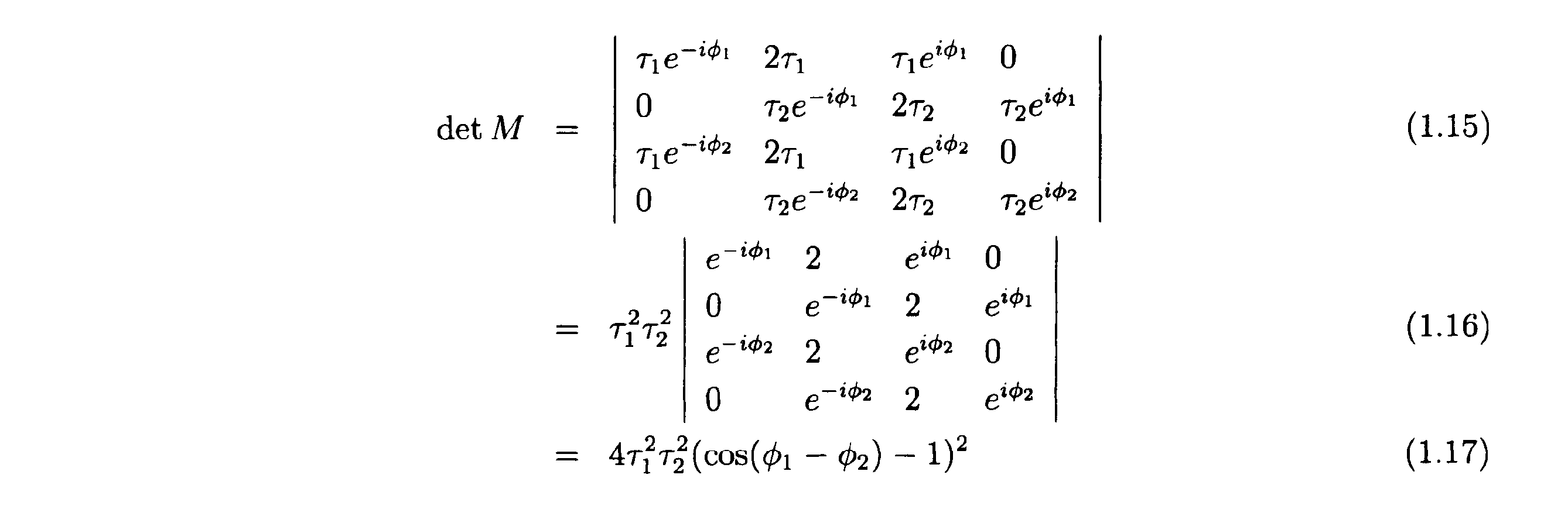
したがって、第1の変調画像の位相φ1と、第2の変調画像の位相φ2との位相差Δφが、Δφ≠0でありさえすれば、detM≠0となり、式1.14は一意的な解を持つ。以上の結果、第1.3節の復調演算に必要な条件は、Δφ≠0であることがわかる。
[第1.3.4節(Δφ=πの特徴)]
本節では、Δφ=πの特徴を説明する。
本節では、Δφ=πの特徴を説明する。
Δφ=πのときには、以下の式が成り立つ。

この場合、

に掛かる位相が等しくなるので、I0(ξ)については簡単に解けて、

となる。したがって、Δφ=πとすれば、通常解像領域において復元できない領域を無くすことができる。
図12(A)の塗りつぶし領域は、Δφ≠πのときに復元可能な範囲であるのに対して、図12(B)の塗りつぶし領域は、Δφ=πのときに復元可能な範囲である(何れも、|ξ0|=2NAの場合。)。図12における2つの円のうち、内側の円は、通常解像範囲の外縁(|ξ|=2NA)であり、外側の円は、超解像範囲の外縁(|ξ|=4NA)である。
なお、ここでは干渉縞の方向数を1と仮定したが、干渉縞の方向数を3とし、各方向について第1.3節と同様の復調演算を適用したならば、図13に示すような広い領域を復元することができる。
[第1.4節(2D-SIMのTwo-pass 復元)]
本節では、本実施形態の2D-SIMの復調演算として、「Two-pass 復元」を説明する。Two-pass 復元では、干渉縞の方向数は2に設定される。
本節では、本実施形態の2D-SIMの復調演算として、「Two-pass 復元」を説明する。Two-pass 復元では、干渉縞の方向数は2に設定される。
以下、互いに方向及び周期(ピッチ)の異なる複数の干渉縞を区別するために、個々の干渉縞を波数ベクトルで表す。この波数ベクトルの大きさは、干渉縞の空間周波数の大きさを示し、波数ベクトルの方向は、干渉縞の方向を示す。
本節では、以下の4つのステップが実行される。
第1ステップ:波数ベクトルがξ0であり、かつ、位相の異なる2枚の変調画像が取得され、それら2枚の変調画像の各々のスペクトルが生成される。これら2枚の変調画像の各々を、以下のとおり表す。

さらに、これら2枚の変調画像の各々のスペクトルに対して第1.3節と同様の復調演算を施すことにより、図14(A)に示す領域の復元値を求める。
第2ステップ:波数ベクトルがξ1であり、かつ、位相の異なる2枚の変調画像が取得され、それら2枚の変調画像の各々のスペクトルが生成される。これら2枚の変調画像の各々を、以下のとおり表す。

さらに、これら2枚の変調画像の各々のスペクトルに対して第1.3節と同様の復調演算を施すことにより、図14(B)に示す領域の復元値を求める。
第3ステップ:以上のステップで求めた復元値と、以下の式とに基づき、図15(A)に示す領域の復元値を求める。

すなわち、以上のステップで求めた復元値、すなわち、

を式1.26へ当てはめることで、図15(A)に示す領域の復元値を求める。なお、式1.26は、式1.24と式1.25とを、

について解いた式である。

ただし、本ステップを可能とするために、少なくとも第2ステップでは、Δφ≠πn(n は整数)とする。
第4ステップ:第2ステップで求めた通常解像範囲の復元値(=図14(B)の塗りつぶし領域のうち|ξ|<2NAの部分)に基づき同様に、図15(B)に示す領域の復元値を求める。
ただし、本ステップを可能とするために、第1ステップでは、Δφ≠πn(n は整数)とする。
第1ステップと第3ステップをまとめて、図16(B)のように表すこともできる。すなわち、図16(B)の横線において横方向に連なる4つの黒点は、第1ステップで解く式1.14と同等の連立方程式から求まる4つの復元値(未知数)のフーリエ空間(波数空間)における位置を表している。
図16(B)にある2本の縦線の各々において、縦方向に連なる3つの黒点のうち、中央の大きい黒点は、第1ステップの式から求まる1つの既知数のフーリエ空間(波数空間)における位置を示しており、両端の小さな黒点は、第3ステップで解く連立方程式1.26の2つの復元値(未知数)のフーリエ空間(波数空間)における位置を示している。
これらの8つの黒点の相互の位置関係は、どの例を選んでも同一である。フーリエ空間(波数空間)において黒点の取りうる位置の範囲は、フーリエ空間(波数空間)において2つの大きな黒点(中央)の取りうる位置の範囲によって制限される。2つの大きな黒点が取りうる位置の範囲は|ξ|<2NAであるので、第1ステップ及び第3ステップの計算によって求めることができる復元値(未知数)の位置の範囲は、図16(B)の塗りつぶし領域の範囲となる。
なお、図16(A)は、第2ステップ及び第4ステップを、図16(B)と同様に示したものである。
したがって、本節では、図17に示す塗りつぶし領域の全域を復元することができる。
[第1.5節(2D-SIMの超解像の例)]
本節では、前節までの結果を踏まえ、超解像の例を2つ説明する。
本節では、前節までの結果を踏まえ、超解像の例を2つ説明する。
先ず、第1の例では、変調画像の枚数(スペクトルの数)を抑えることを重視し、Two-pass 復元を行う。そのために、第1の例では、波数ベクトルの方向数を2とし、互いに異なる2つの波数ベクトルξ1、ξ2の各々で、位相の異なる2枚の変調画像を取得し(合計4枚の変調画像を取得し)、それら4枚の変調画像の各々のスペクトルを生成する(合計4つのスペクトルを生成する)。そして、Two-pass 復元を可能とするため、同一の波数ベクトルで取得される2枚の変調画像間の位相差Δφを、Δφ≠πに設定する。また、波数ベクトルの大きさ|ξi|を、|ξi|=2NAに設定する(i=1、2)。この場合、図17に示す塗りつぶし領域が復元される。
次に、第2の例では、演算精度を重視し、Two-pass 復元ではなく「2画像2点復元」を行う。そのために、第2の例では、波数ベクトルの方向数を3とし、互いに異なる3つの波数ベクトルξ1、ξ2、ξ3の各々で、位相の異なる2枚の変調画像を取得し(合計6枚の変調画像を取得し)、それら6枚の変調画像の各々のスペクトルを生成する(合計6つのスペクトルを生成する)。そして、同一の波数ベクトルで取得される2枚の変調画像間の位相差Δφを、Δφ=πとする。また、復元領域に隙間が生じるのを避けるために、|ξi|を2NAより意図的に小さくする。具体的には、復元領域に隙間が生じない範囲内で|ξi|を最大にするために、波数ベクトルの大きさ|ξi|を、|ξi| =(√3)×NAに設定する(i=1、2)。この場合、図18に示す領域が復元される。
[第1.6節(2D-SIMの4画像3点復元)]
本節では、本実施形態の2D-SIMの復調演算として、2D-SIMの「4画像3点復元」を説明する。
本節では、本実施形態の2D-SIMの復調演算として、2D-SIMの「4画像3点復元」を説明する。
本節では、波数ベクトルの方向数を3とする(3つの波数ベクトルξ1、ξ2、ξ3の各々で変調画像を取得し、それら変調画像の各々のスペクトルを生成する。)。
また、3つの波数ベクトルξ1、ξ2、ξ3を閉じた関係(ξ3=ξ1-ξ2)に設定する。
そして、3つの方向のうち何れか1つの方向(波数ベクトルξ1)では、位相数を2とする(縞方向が同じであり位相の異なる2枚の変調画像I(0)、I(1)を得る)が、他の2つの方向(波数ベクトルξ2、ξ3)の各々では、位相数を1に抑える(縞方向の異なる2枚の変調画像I(2)、I(3)を得る)。
また、縞方向が同じである2枚の変調画像間の位相差Δφは、Δφ=πに設定する。
また、本節では、個々の波数ベクトルの大きさを、|ξi| =2NAに設定する(i=1、2、3)。
このとき、4枚の変調画像I(0)、I(1)、I(2)、I(3)の各々の干渉縞強度分布は、

と表される。
ここで、これら4枚の変調画像I(0)、I(1)、I(2)、I(3)の各々のスペクトルにおいて、3つの波数ベクトルξ1、ξ2、ξ3が描く三角形を想定し、その三角形の頂点(大きな黒点)に位置する3つの観測点ξ、(ξ+ξ1)、(ξ+ξ2)に着目する。
本節で取得した4枚の変調画像I(0)、I(1)、I(2)、I(3)の各々のスペクトルにおける3つの観測点ξ、(ξ+ξ1)、(ξ+ξ2)からは、合計12個の観測値が得られるので、それら12個の観測値に対応する式1.7相当の式を、12個分、取得することができる。本節では、これら12式からなる連立方程式を解くために、以下の条件が必要となる。

図19は、計算の図解である。ただし、|ξ1|=|ξ2|、ξ1・ξ2=|ξ1||ξ2|/2とした。
図19(A)における3つの大きな黒点は、変調画像のスペクトルにおいて3つの波数ベクトルξ1、ξ2、ξ3によって描かれる三角形の頂点に位置する3つの観測点を示しており、図19(A)における3つの大きな黒点及び9つの小さな黒点は、それら3つの観測点から復元される復元点(合計12個の復元点)を示している。
上記したとおり本節において変調画像の枚数(スペクトルの数)は4であるので、3つの観測点から合計12個の観測値が取得される。これら12個の観測値に関する12個の式を連立させて解くことによって、12個の復元点の復元値が個別に求まる。
そして、本節では、3つの観測点を移動させながら、12個の復元値の算出を繰り返すことで、図19(A)に示す塗りつぶし領域全域の復元値を求める。
なお、図19(B)は、三角形の方向を反転させて同様の復元を行った場合の図解である。図19(A)の復元と、図19(B)の復元とは、並行して行うことが可能である。本節では、これら2通りの復元を行い、図20に示した塗りつぶし領域の全域を復元する。
図20は、図19(A)に示した復元領域と、図19(B)に示した復元領域と合成したものである。
以下、本節で述べた12式から成る連立方程式を解く計算の一例を詳しく説明する。
図21は、本節の計算を3つのステップに分けて説明した図である。
図21(A)は、第1ステップで復元される4つの復元点1~4を示している。
図21(B)は、第2ステップで復元される4つの復元点5~8を示している。
図21(C)は、第3ステップで復元される4つの復元点9~12を示している
図21(D)は、図中の番号1~12と復元値との対応関係を示している。
図21(D)は、図中の番号1~12と復元値との対応関係を示している。
第1ステップ:波数ベクトルξ1の方向に間隔|ξ1|で並ぶ2つの観測点1、2に関する4つの観測値を、2画像2点復元の式へ当てはめることにより、復元点1、2、3、4の各々の復元値を求める。
第2ステップ:復元点1、2の各々の復元値を使用して、それら復元点1、2から波数ベクトルξ2、ξ3の分だけずれた4つの復元点5、6、7、8 の各々の復元値を求める。この際に使用される式は、波数ベクトルξ1の方向に関する2つの式(2位相分)と、波数ベクトルξ2の方向に関する1つの式と、波数ベクトルξ3の方向に関する1つの式と、の合計4つの式である。
第3ステップ:復元点1、2、5の各々の復元値を使用して、それら復元点1、2、5から波数ベクトルξ2、ξ3の分だけずれた残りの復元点9、10、11、12の各々の復元値を求める。この際に使用される式は、波数ベクトルξ2の方向に関する2つの式(観測点2つ分)と、波数ベクトルξ3の方向に関する2つの式(観測点2つ分)と、の合計4つの式である。
もちろん、本節で述べた12式から成る連立方程式の解法は、上記の手順に限られるものではない。
[第1.7節(2D-SIMの4画像3点復元の変形例)]
本節では、4画像3点復元の変形例を説明する。
本節では、4画像3点復元の変形例を説明する。
本節では、3つの方向の全ての位相数を1に抑え、その代わりに、1枚の無変調画像を取得し、その無変調画像のスペクトルを生成する。
無変調画像は、K(0)=1で取得された画像のことであって、例えば上述した回折格子16及び光束選択部18を光路から外した状態で取得することができる。また、無変調画像のスペクトルは、その無変調画像をフーリエ変換したものである。
上記したとおり本節において変調画像の枚数(変調画像のスペクトルの数)は3、無変調画像の枚数(無変調画像のスペクトルの数)は1であるので、3つの観測点から合計12個の観測値が取得される。これら12個の観測値に関する12個の式(変調画像のスペクトルに関する式1.7を9つと、無変調画像のスペクトルに関する式1.53を3つと)を連立させて解くことによって、12個の復元点の復元値が個別に求まる。
なお、本節では、以下の条件が必要となる。

[第1.9節(2D-SIMの同時3方向4画像3点復元)]
本節では、4画像3点復元の変形例として、「同時3方向4画像3点復元」を説明する。
本節では、4画像3点復元の変形例として、「同時3方向4画像3点復元」を説明する。
先ず、本節では、標本へ投影する干渉縞は、以下のとおり方向の異なる3つの干渉縞の足しあわせ(3方向干渉縞)とされる。なお、3方向干渉縞の投影方法は後述する。

つまり、本節では、3つの波数ベクトルξ1、ξ2、ξ3を同時に有する3方向干渉縞を採用し、この3方向干渉縞で、位相の互いに異なる4枚の変調画像を取得し、それら4枚の変調画像の各々のスペクトルを生成する。
ただし、|ξi|≦2NAとし(i=1、2、3)、3つの波数ベクトルξ1、ξ2、ξ3を閉じた関係(ξ3=ξ1-ξ2)とする。
また、3方向干渉縞の振幅を規定するaの値は、以下の式を満たすように選択されるものとする。

先ず、本節で取得された或る1枚の変調画像のスペクトルにおける或る観測点ξには、復調画像のスペクトルにおける復元点ξに与えるべき復元値と、復調画像のスペクトルにおける復元点(ξ±ξi)に与えるべき復元値(i=1、2、3)と、の合計7つの復元点の復元値が重畳されている。
言い換えると、変調画像のスペクトルにおける或る観測点ξには、蛍光の0次変調成分と、波数ベクトルξ1による蛍光の±1次変調成分と、波数ベクトルξ2による蛍光の±1次変調成分と、波数ベクトルξ3による蛍光の±1次変調成分と、の合計7成分が重畳されている。
ここで、変調画像のスペクトルにおいて3つの波数ベクトルξ1、ξ2、ξ3が描く三角形を想定し、その三角形の頂点に位置する3つの観測点ξ、(ξ+ξ1)、(ξ+ξ2)に着目する。
これら3つの観測点ξ、(ξ+ξ1)、(ξ+ξ2)の全体には、12個の復元点の復元値が含まれている。
図22は、その図解である。ただし、|ξ1|=|ξ2|、ξ1・ξ2=|ξ1||ξ2|/2とした。
図22(A)における3つの大きな黒点は、変調画像のスペクトルにおいて3つの波数ベクトルξ1、ξ2、ξ3によって描かれる三角形の頂点に位置する3つの観測点を示しており、図22(A)における3つの大きな黒点及び9つの小さな黒点は、それら3つの観測点から復元される復元点(合計12個の復元点)を示している。
上記したとおり本節において変調画像の枚数(スペクトルの数)は4であるので、3つの観測点から合計12個の観測値が取得される。これら12個の観測値に関する12個の式を連立させて解くことにより、12個の復元点の復元値が個別に求まる。
そして、本節では、3つの観測点を移動させながら、12個の復元値の算出を繰り返せば、図22(A)に示す塗りつぶし領域全域の復元値を求める。
なお、図22(B)は、三角形の方向を反転させて同様の復元を行った場合の図解である。図22(A)の復元と、図22(B)の復元とは、並行して行うことが可能である。本節では、これら2通りの復元を行い、図20に示した塗りつぶし領域と同じ領域を復元する。
ここで、4枚の変調画像I(1)、I(2)、I(3)、I(4)の各々に反映されている3方向干渉縞の位相(3成分からなる)は、例えば、

すなわち、4枚の変調画像I(1)、I(2)、I(3)、I(4)の各々における干渉縞強度分布は、以下のとおり。

因みに、4枚の変調画像における干渉縞強度分布の和は、以下の通りである。

つまり、このような干渉強度分布及び位相の組み合わせの下で4枚の変調画像を取得したならば、標本の各部が互いに等しい光量で照明されることになる。4枚の変調画像間で、3方向干渉縞のパターンは共通、かつ、パターンの位置のみがシフトした関係になっている。よって、次の関係が成り立つ。

ただし、a1、a2は、干渉縞の周期構造を結晶格子に見立てたときの格子の基本ベクトルであって、逆格子ベクトル(波数ベクトル)kiを、k1=(2π/λ)ξ1、k2=(2π/λ)ξ2、k3=eZとおくと(eZ:z方向の単位ベクトル)、以下の式で与えられる。

図23は、3方向干渉縞の格子構造と、格子の基本ベクトルa1、a2との関係を示す図である。
図24は、4枚の変調画像の間における干渉縞強度分布の関係を示す図である。
図24に示すとおり、4枚の変調画像の間では、格子パターンが互いに重ならないように平行移動している。また、その移動量の単位は、格子の基本ベクトルの半分となっている。
[第1.9.2節(3方向干渉縞の投影方法)]
ここで、3方向干渉縞の投影方法を説明する。
ここで、3方向干渉縞の投影方法を説明する。
3方向干渉縞を上述した構造化照明顕微鏡装置1で生起させる際には、他の干渉縞(1方向干渉縞)を生起させる場合と同様、上述した回折格子16(図2(A))を使用することができる。
但し、光束選択部材20の開口パターンは、回折格子16において生成する3群の回折光のうち、各群の0次回折光と各群の2次以降の高次回折光と各群の+1次回折光とをカットし、かつ、各群の-1次回折光のみを透過するように設定される。これによって、瞳面上に形成される集光点は、3つの-1次回折光による集光点のみとなる。図25(A)は、光束選択部材20によって余分な回折光がカットされなかった場合の集光点の配置を示しており、図25(B)は、光束選択部材20によって余分な回折光がカットされた場合の集光点の配置を示している。この場合、120°ずつずれた位置に3つの集光点が形成される。これら3つの集光点から射出した3つの回折光(ここでは3つの-1次回折光)は、3方向から標本の照明エリアへ入射し、標本上に3方向干渉縞を形成する。なお、ここでは、干渉縞に寄与する回折光を3つの-1次回折光としたが、3つの+1次回折光としてもよいことは言うまでもない。
但し、この場合、3方向干渉縞として、3通りの2光束干渉縞の重ね合わせではなく、3光束干渉縞が生起してしまうので、超解像効果が低くなってしまう。また、±1次回折光の一方をカットするので、レーザ光の利用効率が低くなってしまう。
そこで、次のとおりにしてもよい。すなわち、独立した3つのレーザ光源A、B、Cを用意し、レーザ光源Aから射出したレーザ光、レーザ光源Bから射出したレーザ光、レーザ光源Cから射出したレーザ光の各々を、2分岐ファイバで分岐し、6つの点光源a、a’、b、b’、c、c’を形成する。なお、点光源a、a’は、レーザ光源Aから生成された可干渉な光源であり、点光源b、b’は、レーザ光源Bから生成された可干渉な光源であり、点光源c、c’は、レーザ光源Cから生成された可干渉な光源である。そして、ファイバを適切に配線することにより、それら6つの点光源a、a’、b、b’、c、c’を、図26に示すような位置関係で瞳共役面へ配置する。つまり、点光源a、a’の配列方向と、点光源b、b’の配列方向と、点光源c、c’の配列方向とは、120°ずつ異なる互いに異なる方向に設定される。これら6つの点光源から射出した6つのレーザ光は、6方向から標本の照明エリアへ入射し、標本上に3方向干渉縞を形成する。
ここで、点光源a、a’から射出したレーザ光La、La’と、点光源b、b’から射出したレーザ光Lb、Lb’と 、点光源c、c’から射出したレーザ光Lc、Lc’とは、互いに干渉しない。したがって、標本上に形成される干渉縞は、3通りの2光束干渉縞の重ね合わせとなる。よって、超解像効果が低くなることはなく、レーザ光の利用効率も高い。
なお、このように、光の分岐手段として回折格子16の代わりに2分岐ファイバが使用された場合は、3方向干渉縞の位相(3成分からなる)を変化させるために、回折格子16を並進移動させる代わりに、レーザ光La、a’の位相差と、レーザ光Lb、Lb’の位相差と、レーザ光Lc、Lcの位相差とをそれぞれ変化させればよい。
[第2.1節(3D-SIMの前提)]
本節では、3D-SIMの復調演算の前提を説明する。
本節では、3D-SIMの復調演算の前提を説明する。
ここでは、3D-SIMにおける干渉縞強度分布を、以下のとおり仮定する。
3光束干渉の波長をλとおくと、3D-SIMにおける干渉縞強度分布K(r) は、以下のとおり表される。

ただし、k0= 2π/λ、j=-1、0、+1として、ベクトルkjを以下の通り定義する。

ここで、ξ0・eZ=0とした。
簡単のため、a0=1、a+=a=|a|eiφ、a-=a*=|a|e-iφと仮定すると、

となるので、干渉縞強度分布Kは、以下のとおり表される。縞は、正弦波状の強度分布を有する第1の周期の縞(中央光とその左右の光からなる3光束のうち、左右の光による干渉縞)と、正弦波状の強度分布を有する第2の周期(第1の周期の2倍)の縞(中央光とその左右の光からなる3光束のうち、中央光と右光(又は左光)による干渉縞)とが重畳したものからなる。

ここで、ζ0=√[1-ξ0
2]-1とおくと、

と表せる。これを、zに依存する成分とxに依存する成分とに分離して、

とおく。ただし、


となる。ただし、J-1=J1
*、J-2=J2
*とする。
さて、標本の蛍光物質密度をI0(x)とし、以上の干渉縞強度分布Kの干渉縞を標本へ投影したときに、標本の蛍光強度分布は、I0(r)K(r)で表されると仮定し、標本の各点で発生した蛍光は他の点の蛍光物質を励起しないという近似(Born 近似)を採用する。
このとき、3D-SIMモードで取得される変調画像I(x、z)は、次のように表される。

すなわち、

ここで、干渉縞のz方向(光軸方向)の起点を、観測点のz座標(z’)が常に中心となるように設定したならば、

3次元OTFを、

とおくと、

そして、変調画像をフーリエ空間で表したもの(すなわち変調画像の空間周波数スペクトル)は、以下のとおり表される。

これを書き下すと、以下のとおりとなる。

ただし、第一項の係数が1 となるように、

とした。なお、a、b、cは、3D-SIMの干渉縞に寄与する3光束(±1次回折光及び0次回折光)の強度バランスによって決まる値である。
以下、フーリエ空間上の空間周波数スペクトルを単に「スペクトル」と称す。また、以下では、この式に現れるφを「位相」と称す。
[第2.2節(従来の3D-SIM)]
本節では、比較のため、従来の3D-SIMの復調演算を説明する。
本節では、比較のため、従来の3D-SIMの復調演算を説明する。
先ず、3D-SIMモードで取得される変調画像のスペクトルにおける観測点ξには、蛍光の-1次変調成分、蛍光の+1次変調成分、蛍光の+2次変調成分、蛍光の+2次変調成分、蛍光の0次変調成分の5成分が重畳されている。観測点ξに重畳された±1次変調成分は、復調画像のスペクトルにおける復元点(ξ±ξ0)が有するべき値(復元値)であり、観測点ξに重畳された±2次変調成分は、復調画像のスペクトルにおける復元点(ξ±2ξ0)が有するべき値(復元値)であり、観測点ξに重畳された0次変調成分は、復調画像のスペクトルにおける復元点ξが有するべき値(復元値)である。
つまり、観測点ξに重畳された±1次変調成分は、正弦波状の強度分布を有する第2の周期(第1の周期の2倍)の縞(中央光とその左右の光からなる3光束のうち、中央光と右光(又は左光)による干渉縞)によって変調された成分であり、観測点ξに重畳された±2次変調成分は正弦波状の強度分布を有する第1の周期の縞(中央光とその左右の光からなる3光束のうち、左右の光による干渉縞)によって変調された成分である。
このことは、変調画像のスペクトルの各観測点について当てはまる。図27における大きな黒点は、或る観測点に対応し、大きな黒点及びその両側の小さな4つの黒点は、その観測点から復元される5つの復元点に対応している。
そこで、従来の3D-SIMの復調演算では、変調画像のスペクトルの各観測点に重畳された5つの変調成分を互いに分離するために、位相の異なる5枚の変調画像を取得し、それらの変調画像の各々のスペクトルを生成していた。従来は、これらのスペクトルが満たす5つの方程式を連立させて解くことで、図27における塗りつぶし領域(通常解像範囲及び超解像範囲)の復元値を求めていた。
[第2.4節(3D-SIMの9画像2点復元)]
本節では、本実施形態の3D-SIMの復調演算として、「9画像2点復元」を説明する。本節における変調画像の取得は、上述した制御装置43が各部を制御して行うものとし、本節における演算は、上述した画像記憶・演算装置44が実行するものとする(他の節においても同様。)。
本節では、本実施形態の3D-SIMの復調演算として、「9画像2点復元」を説明する。本節における変調画像の取得は、上述した制御装置43が各部を制御して行うものとし、本節における演算は、上述した画像記憶・演算装置44が実行するものとする(他の節においても同様。)。
本節では、3D-SIMで取得される1枚の変調画像のスペクトルにおいて、変調方向にかけて変調周波数ξ0だけ離れた2つの観測点ξ、(ξ+ξ0)には、互いに値の共通する変調成分が重畳されていることに着目する。
具体的には、観測点ξに重畳した蛍光の-1次変調成分と、観測点(ξ+ξ0)に重畳した蛍光の0次変調成分とは、何れも復元点(ξ+ξ0)の復元値に相当し、観測点ξに重畳した蛍光の-2次変調成分と、観測点(ξ+ξ0)に重畳した蛍光の-1変調成分とは、何れも復元点(ξ+2ξ0)の復元値に相当し、観測点(ξ+ξ0)に重畳した蛍光の+1次変調成分と、観測点ξに重畳した蛍光の0次変調成分とは、復元点ξの復元値に相当し、観測点(ξ+ξ0)に重畳した蛍光の+2次変調成分と、観測点ξに重畳した蛍光の1次変調成分とは、何れも(ξ-ξ0)の復元値に相当する。つまり、これら2つの観測点ξ、(ξ+ξ0)には、互いに共通する4つの復元点(ξ-ξ0)、ξ、(ξ+ξ0)、(ξ+2ξ0)の復元値が含まれている。
本節の9画像2点復元では、この関係を利用する。以下、具体的に説明する。
1枚の変調画像のスペクトルにおいて、観測点ξの観測値と、観測点(ξ+ξ0)の観測値とは、以下の式で表される。
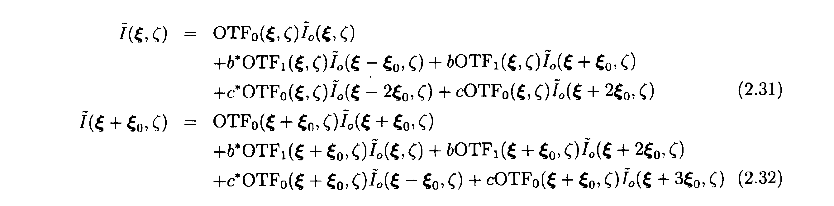
そこで、本節では、同一の波数ベクトルξ0で互いに位相φの異なる3枚の変調画像を取得し、それら3枚の変調画像の各々のスペクトルを生成し、それら3つのスペクトルの各々から、2つの観測点ξ、(ξ+ξ0)に関する合計6個の観測値を参照し、それら6つの観測値を、これらの式へ当てはめることにより、6個の復元値(未知数)を含んだ合計6個の式を取得する。
図28は、本節の3D-SIMの復調画像の周波数域を示す図である。図28(A)はxy断面、図28(B)は、zx断面である。
図28における大きな黒点は、ξ0だけずれた或る2つの観測点ξ、(ξ+ξ0)を示しており、図28における2つの大きな黒点及び4つの小さな黒点は、それらの観測点ξ、(ξ+ξ0)から復元される復元点(合計6つの復元点)を示している。
以上の説明は、或る波数ベクトル(1方向)に関する復元の説明である。
よって、本節では、互いに方向の異なる3つの波数ベクトルの各々で位相の異なる3枚の変調画像を取得し、それら変調画像の各々のスペクトルを生成し、それらのスペクトルに対して方向毎に上記と同様の復元処理を施す。これによって、周波数範囲の広い復調画像を得ることができる。
なお、本節では、同一の波数ベクトルで取得される3枚の変調画像間の位相差Δφは、2π/3に設定されることが望ましい。
[第2.5節(3D-SIMの7画像3点復元)]
本節では、3D-SIMの7画像3点復元を説明する。本節は、無変調画像のスペクトルを利用した第1.7節を3D-SIMに応用したものである。
本節では、3D-SIMの7画像3点復元を説明する。本節は、無変調画像のスペクトルを利用した第1.7節を3D-SIMに応用したものである。
先ず、本節では、方向数(波数ベクトルの数)を3とする。
つまり、本節では、3つの波数ベクトルξ1、ξ2、ξ3を閉じた関係(ξ3=ξ1-ξ2)にし、かつ、1枚の無変調画像を取得する代わりに、3つの方向の各々の位相数を、1ずつ抑える(2ずつとする。)。
また、本節では、同一の波数ベクトルで取得される2枚の変調画像間の位相差Δφを、Δφ=πに設定する。
また、ここでは3つの波数ベクトルの番号をk(k=1、2、3) とおき、k番目の波数ベクトルで取得された、互いに位相の異なる2枚の変調画像を、以下の通り表す。

また、無変調画像を、I(0)と表す。
式2.23より、以下の式が成り立つ。

ただし、±1次変調成分と±2次変調成分とをそれぞれまとめて、次のように表した。

また、τ0=OTF0(ξ,ζ)、τ0’=OTF1(ξ,ζ)とおいた。
ここで、同一の波数ベクトルで取得される2枚の変調画像間の位相差Δφを、Δφ=πに設定したので、式2.35より、以下の式が成り立つ。

よって、式2.34より、以下の式が得られる。

なお、簡単のため、右辺では添字φkを省略した。
また、0次変調成分(通常解像成分)は、次のように表せる。

以上の式2.39、式2.40、式2.41をまとめて行列で書くと、以下のとおりである。

そこで、本節では、先ず、7枚分の変調画像の各々のスペクトルにおける観測点ξに関する7つの観測値を式2.42へ当てはめることで、式2.42の右辺における7つの復元値、すなわち以下の復元値(±1次変調成分と±2次変調成分および0次変調成分)をそれぞれ求める。

ここからの先の計算は、第1.7節の計算と同様である。すなわち、スペクトル

において、3つの波数ベクトルξk(k=1,2,3)の分だけ互いにずれた任意の3つの観測点に関する12の観測値に基づけば、3つの観測点に重畳された蛍光の+1次変調成分と-1次変調成分とを分離することができる。
また、スペクトル

において、3つの波数ベクトルの2倍分2ξk(k=1,2,3)だけ互いにずれた任意の3つの観測点に関する12の観測値に基づけば、3つの観測点に重畳された蛍光の+2次変調成分と-2次変調成分とを分離することができる。
[第2.6節(3D-SIMの12画像3点復元)]
本節では、画像の枚数(スペクトルの数)の削減よりも演算精度の維持を目的として、方向数(波数ベクトルの数)を3とし、各方向の位相数を4とすることで、合計12枚の変調画像を取得する(合計12個のスペクトルを生成する)。
本節では、画像の枚数(スペクトルの数)の削減よりも演算精度の維持を目的として、方向数(波数ベクトルの数)を3とし、各方向の位相数を4とすることで、合計12枚の変調画像を取得する(合計12個のスペクトルを生成する)。
また、本節では、同一の波数ベクトルで取得される4枚の変調画像間の位相差Δφを、Δφ=π/2に設定する。
また、ここでは方向番号をk(k=1、2、3) とおき、位相番号をl(l=0、1、2、3)とおく。
先ず、±1次変調成分は、式2.35より、

また、±2次変調成分は、式2.36より、

と表される。そして、

が成り立つ。
よって、本節の復調演算を行列で書くと、

となる。
したがって、本節では、12枚の変調画像のスペクトル(12のスペクトル)の観測値をこの式へ当てはめることにより、0次変調成分と±1次変調成分とを分離する。
そして、残る±2次変調成分については、第1.7節と同様の手順で分離する。
このように、本節では、第2.5節の手順を踏まずに±1次変調成分を分離することができるので、高いセクショニング効果が期待できる。
[第2.7節(3D-SIMの8画像3点復元)]
なお、上述した第1.6節を以下の通り3D-SIMに応用してもよい。
なお、上述した第1.6節を以下の通り3D-SIMに応用してもよい。
本節では、方向数(波数ベクトルの数)を3とする。
また、3つの波数ベクトルξ1、ξ2、ξ3を閉じた関係(ξ3=ξ1-ξ2)に設定する。
そして、3つの方向のうち何れか1つの方向(波数ベクトルξ1)については、位相数を4とするが、他の2つの方向の各々の位相数を2に抑える。
つまり、本節では、3つの波数ベクトルξ1、ξ2、ξ3を閉じた関係(ξ3=ξ1-ξ2)にする代わりに、2つの方向の各々の変調画像数を、1ずつ抑える。よって、変調画像の合計数(スペクトルの合計数)は、8となる。
ただし、本節では、第1方向(k=1)の変調画像間の位相差は、Δφ=π/2、第2方向(k=2)の変調画像間の位相差は、Δφ=π、第3方向(k=3)の変調画像間の位相差は、Δφ=πに設定される。
このようにして取得された8枚の変調画像のスペクトルによると、各変調成分を分離することが可能である。すなわち、第1ステップにおいて、第1方向(k=1)に関する4枚の変調画像のスペクトルで0次変調成分を求めてから、第2ステップにおいて、±1次変調成分、±2次変調成分の分離を行えばよい。
1…構造化照明顕微鏡装置、100…レーザユニット、11…光ファイバ、10…照明光学系、30…結像光学系、42…撮像素子、43…制御装置、44…画像記憶・演算装置、45…画像表示装置、12…コレクタレンズ、13…偏光板、14…光束分岐部、17…集光レンズ、18…光束選択部、21…レンズ、22…視野絞り、23…フィールドレンズ、24…励起フィルタ、33…ダイクロイックミラー、31…対物レンズ、34…吸収フィルタ、35…第2対物レンズ、2…標本
Claims (14)
- 縞で標本を空間変調する照明光学系と、
空間変調された前記標本からの観察光束を結像することにより前記標本の変調像を形成する結像光学系と、
前記縞の波数ベクトル及び前記縞の位相の少なくとも一方を制御すると共に、前記変調像を撮像して前記標本の変調画像を取得する取得手段と、
前記取得手段で取得した前記変調画像に基づいて前記標本の画像を生成する演算手段とを備え、
前記取得手段は、
前記波数ベクトルが同じであって前記位相が異なる少なくとも2つの前記変調画像を取得し、
前記演算手段は、
前記取得手段で取得した少なくとも2つの前記変調画像の各々の空間周波数スペクトルにおいて、前記波数ベクトルの分だけ互いにずれた任意の2つの観測点に関する少なくとも4つの観測値に基づいて、前記2つの観測点に重畳された前記観察光束の0次変調成分及び±1次変調成分を互いに分離する
ことを特徴とする構造化照明顕微鏡装置。 - 縞で標本を空間変調する照明光学系と、
空間変調された前記標本からの観察光束を結像することにより前記標本の変調像を形成する結像光学系と、
前記縞の波数ベクトル及び前記縞の位相の少なくとも一方を制御すると共に、前記変調像を撮像して前記標本の変調画像を取得する取得手段と、
前記取得手段で取得した前記変調画像に基づいて前記標本の画像を生成する演算手段とを備え、
前記取得手段は、
互いに閉じた関係の3つの前記波数ベクトルのうち、2つの波数ベクトルの各々で1つの前記変調画像を取得し、他の1つの波数ベクトルで前記位相の異なる少なくとも2つの前記変調画像を取得し、
前記演算手段は、
前記取得手段で取得した少なくとも4つの前記変調画像の各々の空間周波数スペクトルにおいて、前記3つの波数ベクトルの分だけ互いにずれた任意の3つの観測点に関する12の観測値に基づいて、前記3つの観測点に重畳された前記観察光束の0次変調成分及び±1次変調成分を互いに分離する
ことを特徴とする構造化照明顕微鏡装置。 - 請求項2に記載の構造化照明顕微鏡装置において、
前記取得手段は、
前記位相の異なる少なくとも2つの変調画像間の位相差を、πに設定する
ことを特徴とする構造化照明顕微鏡装置。 - 縞で標本を空間変調する照明光学系と、
空間変調された前記標本からの観察光束を結像することにより前記標本の変調像を形成する結像光学系と、
前記縞の波数ベクトル及び前記縞の位相の少なくとも一方を制御すると共に、前記変調像を撮像して前記標本の変調画像を取得する取得手段と、
前記取得手段で取得した前記変調画像に基づいて前記標本の画像を生成する演算手段とを備え、
前記取得手段は、
互いに閉じた関係の3つの前記波数ベクトルの各々で1つの前記変調画像を取得すると共に、1つの無変調画像を取得し、
前記演算手段は、
前記取得手段で取得した3つの前記変調画像及び1つの前記無変調画像の各々の空間周波数スペクトルにおいて、前記3つの波数ベクトルの分だけ互いにずれた任意の3つの観測点に関する12の観測値に基づいて、前記3つの観測点に重畳された前記観察光束の0次変調成分及び±1次変調成分を互いに分離する
ことを特徴とする構造化照明顕微鏡装置。 - 縞で標本を空間変調する照明光学系と、
空間変調された前記標本からの観察光束を結像することにより前記標本の変調像を形成する結像光学系と、
前記縞の波数ベクトル及び前記縞の位相の少なくとも一方を制御すると共に、前記変調像を撮像して前記標本の変調画像を取得する取得手段と、
前記取得手段で取得した前記変調画像に基づいて前記標本の画像を生成する演算手段とを備え、
前記取得手段は、
互いに閉じた関係の3つの前記波数ベクトルを同時に有した前記縞で、前記位相の異なる4つの前記変調画像を取得し、
前記演算手段は、
前記取得手段で取得した4つの前記変調画像の各々の空間周波数スペクトルにおいて、前記3つの波数ベクトルの分だけ互いにずれた任意の3つの観測点に関する12の観測値に基づいて、前記3つの観測点に重畳された前記観察光束の0次変調成分及び±1次変調成分を互いに分離する
ことを特徴とする構造化照明顕微鏡装置。 - 縞で前記標本を空間変調する照明光学系と、
空間変調された前記標本からの観察光束を結像することにより前記標本の変調像を形成する結像光学系と、
前記縞の波数ベクトル及び前記縞の位相の少なくとも一方を制御すると共に、前記変調像を撮像して前記標本の変調画像を取得する取得手段と、
前記取得手段で取得した前記変調画像に基づいて前記標本の画像を生成する演算手段とを備え、
前記取得手段は、
前記波数ベクトルが同じであって前記位相が異なる3つの前記変調画像を取得し、
前記演算手段は、
前記取得手段で取得した3つの前記変調画像の各々の空間周波数スペクトルにおいて、前記波数ベクトルの分だけ互いにずれた任意の2つの観測点に関する6つの観測値に基づいて、前記2つの観測点に重畳された前記観察光束の0次変調成分、±1次変調成分及び±2次変調成分を互いに分離する
ことを特徴とする構造化照明顕微鏡装置。 - 請求項6に記載の構造化照明顕微鏡装置において、
前記取得手段は、
前記3つの変調画像間の位相差を、2π/3に設定する
ことを特徴とする構造化照明顕微鏡装置。 - 請求項6に記載の構造化照明顕微鏡装置において、
前記取得手段は、
方向の異なる3つの前記波数ベクトルの各々で、前記位相の異なる3つの前記変調画像を取得し、
前記演算手段は、
前記3つの波数ベクトルの各々について前記分離を行う
ことを特徴とする構造化照明顕微鏡装置。 - 縞で前記標本を空間変調する照明光学系と、
空間変調された前記標本からの観察光束を結像することにより前記標本の変調像を形成する結像光学系と、
前記縞の波数ベクトル及び前記縞の位相の少なくとも一方を制御すると共に、前記変調像を撮像して前記標本の変調画像を取得する取得手段と、
前記取得手段で取得した変調画像に基づいて前記標本の画像を生成する演算手段とを備え、
前記取得手段は、
互いに閉じた関係の3つの前記波数ベクトルの各々で前記位相の異なる2つの前記変調画像を取得すると共に、1つの無変調画像を取得し、
前記演算手段は、
前記取得手段で取得した6つの前記変調画像及び1つの前記無変調画像の各々の空間周波数スペクトルにおいて、前記3つの波数ベクトルの分だけ互いにずれた任意の3つの観測点に関する21の観測値に基づいて、前記3つの観測点に重畳された前記観察光束の±1次変調成分を互いに分離し、前記3つの波数ベクトルの2倍分だけ互いにずれた任意の3つの観測点に関する21の観測値に基づいて、前記3つの観測点に重畳された前記観察光束の0次変調成分及び±2次変調成分を互いに分離する
ことを特徴とする構造化照明顕微鏡装置。 - 請求項9に記載の構造化照明顕微鏡装置において、
前記取得手段は、
少なくとも1つの前記波数ベクトルで取得される2つの前記変調画像間の位相差を、πに設定する
ことを特徴とする構造化照明顕微鏡装置。 - 縞で前記標本を空間変調する照明光学系と、
空間変調された前記標本からの観察光束を結像することにより前記標本の変調像を形成する結像光学系と、
前記縞の波数ベクトル及び前記縞の位相の少なくとも一方を制御すると共に、前記変調像を撮像して前記標本の変調画像を取得する取得手段と、
前記取得手段で取得した変調画像に基づいて前記標本の画像を生成する演算手段とを備え、
前記取得手段は、
互いに閉じた関係の3つの前記波数ベクトルの各々で前記位相の異なる4つの変調画像を取得し、
前記演算手段は、
前記取得手段で取得した12の前記変調画像の各々の空間周波数スペクトルにおいて、前記3つの波数ベクトルの分だけ互いにずれた任意の3つの観測点に関する36の観測値に基づいて、前記3つの観測点に重畳された前記観察光束の±1次変調成分を互いに分離し、前記3つの波数ベクトルの2倍分だけ互いにずれた任意の3つの観測点に関する36の観測値に基づいて、前記3つの観測点に重畳された前記観察光束の0次変調成分及び±2次変調成分を互いに分離する
ことを特徴とする構造化照明顕微鏡装置。 - 縞で前記標本を空間変調する照明光学系と、
空間変調された前記標本からの観察光束を結像することにより前記標本の変調像を形成する結像光学系と、
前記縞の波数ベクトル及び前記縞の位相の少なくとも一方を制御すると共に、前記変調像を撮像して前記標本の変調画像を取得する取得手段と、
前記取得手段で取得した変調画像に基づいて前記標本の画像を生成する演算手段とを備え、
前記取得手段は、
互いに閉じた関係の3つの前記波数ベクトルのうち、2つの波数ベクトルの各々で前記位相の異なる2つの前記変調画像を取得し、他の1つの波数ベクトルで前記位相の異なる4つの前記変調画像を取得し、
前記演算手段は、
前記取得手段が取得した8つの前記変調画像の各々の空間周波数スペクトルにおいて、前記3つの波数ベクトルの分だけ互いにずれた任意の3つの観測点に関する24の観測値に基づいて、前記3つの観測点に重畳された前記観察光束の±1次変調成分を互いに分離し、前記3つの波数ベクトルの2倍分だけ互いにずれた任意の3つの観測点に関する24の観測値に基づいて、前記3つの観測点に重畳された前記観察光束の0次変調成分及び±2次変調成分を互いに分離する
ことを特徴とする構造化照明顕微鏡装置。 - 請求項12に記載の構造化照明顕微鏡装置において、
前記取得手段は、
前記位相の異なる4つの変調画像間の位相差を、π/2に設定する
ことを特徴とする構造化照明顕微鏡装置。 - 請求項2~5、請求項9~13の何れか一項に記載の構造化照明顕微鏡装置において、
前記3つの波数ベクトルは、大きさが同じであって、方向が120°ずつずれたベクトルである
ことを特徴とする構造化照明顕微鏡装置。
Priority Applications (4)
| Application Number | Priority Date | Filing Date | Title |
|---|---|---|---|
| JP2014525717A JP5888416B2 (ja) | 2012-07-19 | 2013-07-16 | 構造化照明顕微鏡装置 |
| US14/597,495 US10261304B2 (en) | 2012-07-19 | 2015-01-15 | Structured illuminating microscopy apparatus |
| US16/290,149 US11187883B2 (en) | 2012-07-19 | 2019-03-01 | Structured illuminating microscopy apparatus |
| US17/513,391 US20220050283A1 (en) | 2012-07-19 | 2021-10-28 | Structured illuminating microscopy apparatus |
Applications Claiming Priority (2)
| Application Number | Priority Date | Filing Date | Title |
|---|---|---|---|
| JP2012-160805 | 2012-07-19 | ||
| JP2012160805 | 2012-07-19 |
Related Child Applications (1)
| Application Number | Title | Priority Date | Filing Date |
|---|---|---|---|
| US14/597,495 Continuation US10261304B2 (en) | 2012-07-19 | 2015-01-15 | Structured illuminating microscopy apparatus |
Publications (1)
| Publication Number | Publication Date |
|---|---|
| WO2014013720A1 true WO2014013720A1 (ja) | 2014-01-23 |
Family
ID=49948562
Family Applications (1)
| Application Number | Title | Priority Date | Filing Date |
|---|---|---|---|
| PCT/JP2013/004338 Ceased WO2014013720A1 (ja) | 2012-07-19 | 2013-07-16 | 構造化照明顕微鏡装置 |
Country Status (3)
| Country | Link |
|---|---|
| US (3) | US10261304B2 (ja) |
| JP (1) | JP5888416B2 (ja) |
| WO (1) | WO2014013720A1 (ja) |
Cited By (7)
| Publication number | Priority date | Publication date | Assignee | Title |
|---|---|---|---|---|
| WO2015052936A1 (ja) * | 2013-10-09 | 2015-04-16 | 株式会社ニコン | 構造化照明顕微鏡装置 |
| WO2015162921A1 (ja) * | 2014-04-25 | 2015-10-29 | 株式会社ニコン | 構造化照明顕微鏡装置及び構造化照明観察方法 |
| JP2015212744A (ja) * | 2014-05-02 | 2015-11-26 | オリンパス株式会社 | 標本像データ生成装置、及び、標本像データ生成方法 |
| WO2018096639A1 (ja) * | 2016-11-24 | 2018-05-31 | 株式会社ニコン | 画像処理装置、顕微鏡システム、画像処理方法、およびプログラム |
| CN109983767A (zh) * | 2016-11-24 | 2019-07-05 | 株式会社尼康 | 图像处理装置、显微镜系统、图像处理方法及计算机程序 |
| US10900900B2 (en) | 2015-10-19 | 2021-01-26 | Nikon Corporation | Structured illumination microscope, observation method, and storage medium |
| US20230048871A1 (en) * | 2021-08-13 | 2023-02-16 | The Swatch Group Research And Development Ltd | Portable modular unit for inspecting in a timepiece the presence of a lubricating agent or of an epilame |
Families Citing this family (12)
| Publication number | Priority date | Publication date | Assignee | Title |
|---|---|---|---|---|
| JP5900515B2 (ja) * | 2012-01-18 | 2016-04-06 | 株式会社ニコン | 構造化照明装置、構造化照明顕微鏡装置、構造化照明方法 |
| WO2014013720A1 (ja) * | 2012-07-19 | 2014-01-23 | 株式会社ニコン | 構造化照明顕微鏡装置 |
| JP6635052B2 (ja) * | 2015-02-05 | 2020-01-22 | 株式会社ニコン | 構造化照明顕微鏡、及び観察方法 |
| US10215975B2 (en) * | 2015-02-06 | 2019-02-26 | The Regents Of The University Of Colorado, A Body Corporate | Method and/or system for stabilization, tracking, and/or control of microscopic systems |
| US10989661B2 (en) * | 2015-05-01 | 2021-04-27 | The Board Of Regents Of The University Of Texas System | Uniform and scalable light-sheets generated by extended focusing |
| WO2017180680A1 (en) | 2016-04-12 | 2017-10-19 | The Board Of Regents Of The University Of Texas System | LIGHT-SHEET MICROSCOPE WITH PARALLELIZED 3D lMAGE ACQUISITION |
| NL2020619B1 (en) * | 2018-01-16 | 2019-07-25 | Illumina Inc | Dual optical grating slide structured illumination imaging |
| TWI699559B (zh) * | 2018-01-16 | 2020-07-21 | 美商伊路米納有限公司 | 結構照明成像系統和使用結構化光來創建高解析度圖像的方法 |
| CN110044854B (zh) * | 2018-01-16 | 2024-08-02 | 伊鲁米那股份有限公司 | 图样角度空间选择结构照明成像 |
| NL2020620B1 (en) * | 2018-01-16 | 2019-07-25 | Illumina Inc | Pattern angle spatial selection structured illumination imaging |
| CN111338070B (zh) * | 2020-03-18 | 2021-04-23 | 中国科学技术大学 | 一种结构光产生装置及结构光照明显微镜 |
| JP7572033B2 (ja) * | 2020-10-23 | 2024-10-23 | 株式会社リガク | 結像型x線顕微鏡 |
Citations (4)
| Publication number | Priority date | Publication date | Assignee | Title |
|---|---|---|---|---|
| JP2009098215A (ja) * | 2007-10-12 | 2009-05-07 | Nikon Corp | 顕微鏡装置、及び顕微鏡装置における位相変化量の算出方法。 |
| JP2009157084A (ja) * | 2007-12-26 | 2009-07-16 | Nikon Corp | 顕微鏡装置 |
| US20120026311A1 (en) * | 2010-04-26 | 2012-02-02 | The Regents Of The University Of California | Structured illumination microscope apparatus and an image forming apparatus |
| JP2012504252A (ja) * | 2008-09-30 | 2012-02-16 | カール ツァイス マイクロイメージング ゲーエムベーハー | 構造化照明を備えた顕微鏡法のための改良された方法および装置 |
Family Cites Families (18)
| Publication number | Priority date | Publication date | Assignee | Title |
|---|---|---|---|---|
| US5489986A (en) * | 1989-02-28 | 1996-02-06 | Nikon Corporation | Position detecting apparatus |
| JPH03140840A (ja) * | 1989-10-26 | 1991-06-14 | Hitachi Ltd | 流動細胞分析装置 |
| US5671085A (en) | 1995-02-03 | 1997-09-23 | The Regents Of The University Of California | Method and apparatus for three-dimensional microscopy with enhanced depth resolution |
| US6259561B1 (en) * | 1999-03-26 | 2001-07-10 | The University Of Rochester | Optical system for diffusing light |
| JP4504037B2 (ja) * | 2004-02-02 | 2010-07-14 | 大日本印刷株式会社 | 光学素子 |
| JP4794839B2 (ja) * | 2004-09-17 | 2011-10-19 | キヤノン株式会社 | 反射型液晶表示装置 |
| EP2082200A2 (en) * | 2006-10-05 | 2009-07-29 | Delaware State University Foundation, Inc. | Fiber optics sound detector |
| WO2009031418A1 (ja) * | 2007-09-05 | 2009-03-12 | Nikon Corporation | 顕微鏡装置 |
| US20180307039A1 (en) * | 2008-12-16 | 2018-10-25 | Silicon Light Machines Corporation | High Power Handling Optical Spatial Light Modulator |
| FR2955666B1 (fr) * | 2010-01-26 | 2012-04-13 | Centre Nat Rech Scient | Procede d'estimation de defauts dans un objet et dispositif de mise en oeuvre |
| JP5721042B2 (ja) * | 2010-10-20 | 2015-05-20 | 株式会社ニコン | 顕微鏡システム |
| FR2966937B1 (fr) * | 2010-10-28 | 2012-12-28 | Univ Paris Diderot Paris 7 | Methode d'observation de l'emission de lumiere d'un echantillon par microscopie optique dynamique |
| WO2012145741A2 (en) * | 2011-04-22 | 2012-10-26 | The University Of Memphis Reasearch Foundation | Spatially-selective disks, submillimeter imaging devices, methods of submillimeter imaging profiling scanners, spectrometry devices, and methods of spectrometry |
| JP5900515B2 (ja) * | 2012-01-18 | 2016-04-06 | 株式会社ニコン | 構造化照明装置、構造化照明顕微鏡装置、構造化照明方法 |
| WO2014013720A1 (ja) * | 2012-07-19 | 2014-01-23 | 株式会社ニコン | 構造化照明顕微鏡装置 |
| US9581961B2 (en) * | 2012-10-05 | 2017-02-28 | University Of Hyogo | Holographic microscope, holographic image generation method, and method for acquiring data for holographic image |
| WO2015052936A1 (ja) * | 2013-10-09 | 2015-04-16 | 株式会社ニコン | 構造化照明顕微鏡装置 |
| JP6272145B2 (ja) * | 2014-05-29 | 2018-01-31 | 浜松ホトニクス株式会社 | レーザ加工装置及びレーザ加工方法 |
-
2013
- 2013-07-16 WO PCT/JP2013/004338 patent/WO2014013720A1/ja not_active Ceased
- 2013-07-16 JP JP2014525717A patent/JP5888416B2/ja not_active Expired - Fee Related
-
2015
- 2015-01-15 US US14/597,495 patent/US10261304B2/en active Active
-
2019
- 2019-03-01 US US16/290,149 patent/US11187883B2/en not_active Expired - Fee Related
-
2021
- 2021-10-28 US US17/513,391 patent/US20220050283A1/en not_active Abandoned
Patent Citations (4)
| Publication number | Priority date | Publication date | Assignee | Title |
|---|---|---|---|---|
| JP2009098215A (ja) * | 2007-10-12 | 2009-05-07 | Nikon Corp | 顕微鏡装置、及び顕微鏡装置における位相変化量の算出方法。 |
| JP2009157084A (ja) * | 2007-12-26 | 2009-07-16 | Nikon Corp | 顕微鏡装置 |
| JP2012504252A (ja) * | 2008-09-30 | 2012-02-16 | カール ツァイス マイクロイメージング ゲーエムベーハー | 構造化照明を備えた顕微鏡法のための改良された方法および装置 |
| US20120026311A1 (en) * | 2010-04-26 | 2012-02-02 | The Regents Of The University Of California | Structured illumination microscope apparatus and an image forming apparatus |
Cited By (13)
| Publication number | Priority date | Publication date | Assignee | Title |
|---|---|---|---|---|
| WO2015052936A1 (ja) * | 2013-10-09 | 2015-04-16 | 株式会社ニコン | 構造化照明顕微鏡装置 |
| US10067331B2 (en) | 2013-10-09 | 2018-09-04 | Nikon Corporation | Structured illumination microscope device |
| US10393661B2 (en) | 2014-04-25 | 2019-08-27 | Nikon Corporation | Structured illumination microscopic device and structured illumination observation method |
| WO2015162921A1 (ja) * | 2014-04-25 | 2015-10-29 | 株式会社ニコン | 構造化照明顕微鏡装置及び構造化照明観察方法 |
| JPWO2015162921A1 (ja) * | 2014-04-25 | 2017-04-13 | 株式会社ニコン | 構造化照明顕微鏡装置及び構造化照明観察方法 |
| JP2015212744A (ja) * | 2014-05-02 | 2015-11-26 | オリンパス株式会社 | 標本像データ生成装置、及び、標本像データ生成方法 |
| US10900900B2 (en) | 2015-10-19 | 2021-01-26 | Nikon Corporation | Structured illumination microscope, observation method, and storage medium |
| CN109983767A (zh) * | 2016-11-24 | 2019-07-05 | 株式会社尼康 | 图像处理装置、显微镜系统、图像处理方法及计算机程序 |
| JPWO2018096639A1 (ja) * | 2016-11-24 | 2019-10-17 | 株式会社ニコン | 画像処理装置、顕微鏡システム、画像処理方法、およびプログラム |
| WO2018096639A1 (ja) * | 2016-11-24 | 2018-05-31 | 株式会社ニコン | 画像処理装置、顕微鏡システム、画像処理方法、およびプログラム |
| US11010914B2 (en) | 2016-11-24 | 2021-05-18 | Nikon Corporation | Image processing device, microscope system, image processing method, and program |
| US20230048871A1 (en) * | 2021-08-13 | 2023-02-16 | The Swatch Group Research And Development Ltd | Portable modular unit for inspecting in a timepiece the presence of a lubricating agent or of an epilame |
| US12339230B2 (en) * | 2021-08-13 | 2025-06-24 | The Swatch Group Research And Development Ltd | Portable modular unit for inspecting in a timepiece the presence of a lubricating agent or of an epilame |
Also Published As
| Publication number | Publication date |
|---|---|
| JP5888416B2 (ja) | 2016-03-22 |
| US20150185463A1 (en) | 2015-07-02 |
| US10261304B2 (en) | 2019-04-16 |
| US20190196171A1 (en) | 2019-06-27 |
| US20220050283A1 (en) | 2022-02-17 |
| US11187883B2 (en) | 2021-11-30 |
| JPWO2014013720A1 (ja) | 2016-06-30 |
Similar Documents
| Publication | Publication Date | Title |
|---|---|---|
| JP5888416B2 (ja) | 構造化照明顕微鏡装置 | |
| US10739574B2 (en) | Structured illumination optical system and structured illumination microscope device | |
| WO2015052936A1 (ja) | 構造化照明顕微鏡装置 | |
| US8019136B2 (en) | Optical sectioning microscopy | |
| JP6197880B2 (ja) | 構造化照明顕微鏡、構造化照明方法、及びプログラム | |
| EP2437095B1 (en) | Sample observation device for generating super resolution image | |
| JP5136422B2 (ja) | 顕微鏡装置及び画像処理方法 | |
| JPWO2009031418A1 (ja) | 顕微鏡装置 | |
| US11287625B2 (en) | Microscope and observation method | |
| JP4123305B2 (ja) | 画像作成方法および顕微鏡装置 | |
| WO2007043314A1 (ja) | 顕微鏡装置 | |
| WO2015008415A1 (ja) | 構造化照明装置及び構造化照明顕微鏡装置 | |
| US12094081B2 (en) | Method for super-resolution evaluation of microscope images illuminated in a structured manner and microscope having structured illumination | |
| JP2009098215A (ja) | 顕微鏡装置、及び顕微鏡装置における位相変化量の算出方法。 | |
| JP2015055706A (ja) | 構造化照明装置及び構造化照明顕微鏡装置 | |
| US20220075175A1 (en) | Method for sim microscopy | |
| JP2015212744A (ja) | 標本像データ生成装置、及び、標本像データ生成方法 | |
| JP6286982B2 (ja) | 構造化照明顕微鏡装置 | |
| JPWO2018150471A1 (ja) | 構造化照明顕微鏡、観察方法、及びプログラム | |
| WO2020179032A1 (ja) | 顕微鏡および観察方法 | |
| JP2024044416A (ja) | 勾配光干渉顕微鏡 | |
| WO2020179039A1 (ja) | 顕微鏡および観察方法 | |
| CN107329389A (zh) | 一种层叠衍射成像装置 |
Legal Events
| Date | Code | Title | Description |
|---|---|---|---|
| 121 | Ep: the epo has been informed by wipo that ep was designated in this application |
Ref document number: 13819503 Country of ref document: EP Kind code of ref document: A1 |
|
| ENP | Entry into the national phase |
Ref document number: 2014525717 Country of ref document: JP Kind code of ref document: A |
|
| NENP | Non-entry into the national phase |
Ref country code: DE |
|
| 122 | Ep: pct application non-entry in european phase |
Ref document number: 13819503 Country of ref document: EP Kind code of ref document: A1 |