WO2014010683A1 - 超音波検査装置 - Google Patents
超音波検査装置 Download PDFInfo
- Publication number
- WO2014010683A1 WO2014010683A1 PCT/JP2013/069010 JP2013069010W WO2014010683A1 WO 2014010683 A1 WO2014010683 A1 WO 2014010683A1 JP 2013069010 W JP2013069010 W JP 2013069010W WO 2014010683 A1 WO2014010683 A1 WO 2014010683A1
- Authority
- WO
- WIPO (PCT)
- Prior art keywords
- element data
- unit
- ultrasonic
- data
- transmission
- Prior art date
Links
Images


Classifications
-
- A—HUMAN NECESSITIES
- A61—MEDICAL OR VETERINARY SCIENCE; HYGIENE
- A61B—DIAGNOSIS; SURGERY; IDENTIFICATION
- A61B8/00—Diagnosis using ultrasonic, sonic or infrasonic waves
- A61B8/13—Tomography
- A61B8/14—Echo-tomography
-
- A—HUMAN NECESSITIES
- A61—MEDICAL OR VETERINARY SCIENCE; HYGIENE
- A61B—DIAGNOSIS; SURGERY; IDENTIFICATION
- A61B8/00—Diagnosis using ultrasonic, sonic or infrasonic waves
- A61B8/44—Constructional features of the ultrasonic, sonic or infrasonic diagnostic device
- A61B8/4483—Constructional features of the ultrasonic, sonic or infrasonic diagnostic device characterised by features of the ultrasound transducer
- A61B8/4488—Constructional features of the ultrasonic, sonic or infrasonic diagnostic device characterised by features of the ultrasound transducer the transducer being a phased array
-
- A—HUMAN NECESSITIES
- A61—MEDICAL OR VETERINARY SCIENCE; HYGIENE
- A61B—DIAGNOSIS; SURGERY; IDENTIFICATION
- A61B8/00—Diagnosis using ultrasonic, sonic or infrasonic waves
- A61B8/52—Devices using data or image processing specially adapted for diagnosis using ultrasonic, sonic or infrasonic waves
- A61B8/5207—Devices using data or image processing specially adapted for diagnosis using ultrasonic, sonic or infrasonic waves involving processing of raw data to produce diagnostic data, e.g. for generating an image
-
- A—HUMAN NECESSITIES
- A61—MEDICAL OR VETERINARY SCIENCE; HYGIENE
- A61B—DIAGNOSIS; SURGERY; IDENTIFICATION
- A61B8/00—Diagnosis using ultrasonic, sonic or infrasonic waves
- A61B8/54—Control of the diagnostic device
-
- G—PHYSICS
- G01—MEASURING; TESTING
- G01S—RADIO DIRECTION-FINDING; RADIO NAVIGATION; DETERMINING DISTANCE OR VELOCITY BY USE OF RADIO WAVES; LOCATING OR PRESENCE-DETECTING BY USE OF THE REFLECTION OR RERADIATION OF RADIO WAVES; ANALOGOUS ARRANGEMENTS USING OTHER WAVES
- G01S15/00—Systems using the reflection or reradiation of acoustic waves, e.g. sonar systems
- G01S15/88—Sonar systems specially adapted for specific applications
- G01S15/89—Sonar systems specially adapted for specific applications for mapping or imaging
- G01S15/8906—Short-range imaging systems; Acoustic microscope systems using pulse-echo techniques
- G01S15/8909—Short-range imaging systems; Acoustic microscope systems using pulse-echo techniques using a static transducer configuration
- G01S15/8915—Short-range imaging systems; Acoustic microscope systems using pulse-echo techniques using a static transducer configuration using a transducer array
-
- G—PHYSICS
- G01—MEASURING; TESTING
- G01S—RADIO DIRECTION-FINDING; RADIO NAVIGATION; DETERMINING DISTANCE OR VELOCITY BY USE OF RADIO WAVES; LOCATING OR PRESENCE-DETECTING BY USE OF THE REFLECTION OR RERADIATION OF RADIO WAVES; ANALOGOUS ARRANGEMENTS USING OTHER WAVES
- G01S7/00—Details of systems according to groups G01S13/00, G01S15/00, G01S17/00
- G01S7/52—Details of systems according to groups G01S13/00, G01S15/00, G01S17/00 of systems according to group G01S15/00
- G01S7/52017—Details of systems according to groups G01S13/00, G01S15/00, G01S17/00 of systems according to group G01S15/00 particularly adapted to short-range imaging
- G01S7/52046—Techniques for image enhancement involving transmitter or receiver
-
- G—PHYSICS
- G10—MUSICAL INSTRUMENTS; ACOUSTICS
- G10K—SOUND-PRODUCING DEVICES; METHODS OR DEVICES FOR PROTECTING AGAINST, OR FOR DAMPING, NOISE OR OTHER ACOUSTIC WAVES IN GENERAL; ACOUSTICS NOT OTHERWISE PROVIDED FOR
- G10K11/00—Methods or devices for transmitting, conducting or directing sound in general; Methods or devices for protecting against, or for damping, noise or other acoustic waves in general
- G10K11/18—Methods or devices for transmitting, conducting or directing sound
- G10K11/26—Sound-focusing or directing, e.g. scanning
- G10K11/34—Sound-focusing or directing, e.g. scanning using electrical steering of transducer arrays, e.g. beam steering
- G10K11/341—Circuits therefor
- G10K11/346—Circuits therefor using phase variation
-
- A—HUMAN NECESSITIES
- A61—MEDICAL OR VETERINARY SCIENCE; HYGIENE
- A61B—DIAGNOSIS; SURGERY; IDENTIFICATION
- A61B8/00—Diagnosis using ultrasonic, sonic or infrasonic waves
- A61B8/44—Constructional features of the ultrasonic, sonic or infrasonic diagnostic device
- A61B8/4483—Constructional features of the ultrasonic, sonic or infrasonic diagnostic device characterised by features of the ultrasound transducer
-
- A—HUMAN NECESSITIES
- A61—MEDICAL OR VETERINARY SCIENCE; HYGIENE
- A61B—DIAGNOSIS; SURGERY; IDENTIFICATION
- A61B8/00—Diagnosis using ultrasonic, sonic or infrasonic waves
- A61B8/46—Ultrasonic, sonic or infrasonic diagnostic devices with special arrangements for interfacing with the operator or the patient
- A61B8/461—Displaying means of special interest
- A61B8/463—Displaying means of special interest characterised by displaying multiple images or images and diagnostic data on one display
-
- A—HUMAN NECESSITIES
- A61—MEDICAL OR VETERINARY SCIENCE; HYGIENE
- A61B—DIAGNOSIS; SURGERY; IDENTIFICATION
- A61B8/00—Diagnosis using ultrasonic, sonic or infrasonic waves
- A61B8/46—Ultrasonic, sonic or infrasonic diagnostic devices with special arrangements for interfacing with the operator or the patient
- A61B8/467—Ultrasonic, sonic or infrasonic diagnostic devices with special arrangements for interfacing with the operator or the patient characterised by special input means
- A61B8/469—Ultrasonic, sonic or infrasonic diagnostic devices with special arrangements for interfacing with the operator or the patient characterised by special input means for selection of a region of interest
Definitions
- the present invention relates to an ultrasonic inspection apparatus that images an inspection object such as an organ in a living body by transmitting and receiving an ultrasonic beam to generate an ultrasonic image used for inspection and diagnosis of the inspection object. .
- an ultrasonic inspection apparatus such as an ultrasonic diagnostic imaging apparatus using an ultrasonic image
- this type of ultrasonic inspection apparatus has an ultrasonic probe (ultrasonic probe) including a plurality of elements (ultrasonic transducers), and an apparatus main body connected to the ultrasonic probe.
- the ultrasonic probe transmits the ultrasonic beam from the multiple elements of the ultrasonic probe toward the inspection object (subject), receives the ultrasonic echo from the subject, and receives the ultrasonic echo.
- An ultrasonic image is generated by electrically processing the ultrasonic echo signal thus processed in the apparatus main body.
- an ultrasonic wave is focused on a region to be inspected of a subject, for example, an organ in a living body or a lesion in the organ from a plurality of elements of the probe. Transmits a beam and receives ultrasonic echoes from the surface or interface of a reflector in the examination target area, for example, an organ or a lesion, via multiple elements, but is reflected by the same reflector. Are reflected by the reflector located at the focal position of the ultrasonic beam transmitted from the transmitting element, and reflected by the same reflector with respect to the ultrasonic echo signal received by the transmitting element.
- the ultrasonic echo signals received by other elements different from the transmitting element are delayed, the ultrasonic echo signals received by a plurality of elements are A / D (analog / digital) converted into element data. And then And reception focusing processing child data, i.e. the delay correction to have generated ultrasound image based on the generated sound ray signals by phasing and adding the combined phase, thus obtained sound ray signals.
- Patent Document 1 In Patent Document 1, first, an ultrasonic beam wider than a normal ultrasonic beam (see FIG. 12B in Patent Document 1) is designed and transmitted to obtain received data (see FIG. 4).
- Patent Document 1 polar coordinates (radius R and angle ⁇ ) are assigned to a wide beam, and an ultrasonic image is generated from the relationship between received data and the geometric coordinates.
- the ultrasonic image generated in this way has an image frame rate that is higher than that of the prior art, and can improve the image resolution with respect to the image formation time.
- a wide ultrasonic beam covering a tissue area in a subject is transmitted from a plurality of elements (ultrasonic transducers) while being shifted by one element, and ultrasonic echoes from the tissue area are transmitted.
- the parallel raw data (element data) including the tissue area information generated based on the plurality of received signals by is converted into serial raw data, and the converted raw data is subjected to reception focus processing to generate an image signal (
- An ultrasonic diagnostic apparatus that generates a sound ray signal) and generates an ultrasonic image based on the obtained sound ray signal is disclosed.
- Patent Document 2 when generating a sound ray signal, an ultrasonic beam is transmitted so that two adjacent areas overlap each other, and one sampling point in the overlap region is transmitted a plurality of times.
- signal processing for example, reception focus processing
- one sound ray signal can be generated, and the resolution is reduced due to the widening of the SN ratio and opening.
- an SN value and an aperture are widened by obtaining an average value of the sound ray signals. It is disclosed that it is possible to obtain one sound ray signal with improved resolution that is reduced by the above.
- a virtual point sound source is formed by focusing transmission ultrasonic waves radiated from a plurality of vibration elements constituting a transmission vibration element group on a transmission focal point, and from this point sound source, Received ultrasonic waves reflected from a plurality of continuous observation points by radiated transmitted ultrasonic waves are received by a plurality of vibration elements constituting a reception vibration element group, and observation points are obtained with respect to the received signals for the obtained channels. Receive phasing and addition is performed so that becomes a reception focusing point. Further, similar reception phasing addition is performed on the reception signal obtained using each of the reception vibration element group and the transmission vibration element group sequentially shifted in the arrangement direction of the vibration elements.
- Patent Document 3 discloses an ultrasonic diagnostic apparatus that performs transmission phasing addition for correcting a transmission delay caused by a difference in propagation distance from each transmission focusing point to an observation point with respect to a reception signal after phase addition.
- the reception phasing addition and the transmission phasing addition are performed on the reception signals obtained from a plurality of vibration elements, thereby having a substantially uniform thin beam width in the depth direction of the subject.
- the transmission beam and the reception beam can be formed with high accuracy and high sensitivity. For this reason, Patent Document 3 discloses that image data can be generated and displayed with excellent spatial resolution, contrast resolution, and S / N.
- a reception focus process is performed on a plurality of raw data to obtain one sound ray signal, or a plurality of raw data is subjected to a reception focus process to obtain a sound ray signal, Since only one sound ray signal is obtained by obtaining the average value, there is a limit to the improvement in the SN ratio and resolution degradation due to the wide beam, and a further improvement in the SN ratio cannot be obtained. There was a problem that it was not possible to obtain an ultrasonic image with a high S / N ratio. On the other hand, with the technique disclosed in Patent Document 3, an image with higher image quality than that of the conventional technique can be obtained. Since the number of transmissions is higher than that of the technology, there is a problem that the frame rate is lowered and the real-time property is deteriorated.
- An object of the present invention is to solve the above-mentioned problems of the prior art and superimpose element data acquired by transmission from two or more different elements when transmitting ultrasonic beams from a plurality of elements of an ultrasonic probe. Therefore, it is possible to reduce the influence of the spread of the transmitted ultrasonic beam, increase the signal-to-noise ratio, increase the resolution, and transmit at the same frame rate as before without using a wide beam transmission dedicated ultrasonic probe.
- An object of the present invention is to provide an ultrasonic inspection apparatus capable of obtaining a sharp ultrasonic image having an optimum spatial resolution at a high resolution independent of the beam width.
- an ultrasonic inspection apparatus of the present invention is an ultrasonic inspection apparatus that inspects an inspection object using an ultrasonic beam, and transmits an ultrasonic beam, and the inspection object The reflected ultrasonic echoes are received and an analog element signal corresponding to the received ultrasonic echoes is output.
- the transmission unit that transmits the ultrasonic beam so as to form the transmission focal point of the plurality of times, and the analog element signal output by the plurality of elements, From a receiving unit that performs predetermined processing, an A / D conversion of an analog element signal processed by the receiving unit to obtain first element data that is a digital element signal, and a plurality of first element data , The first element data And a data processing unit for generating second element data corresponding to the above, and the data processing unit generates 2nd element data according to the depth of the position where the second element data is obtained.
- the above-described first element data acquisition condition is changed.
- the transmitter performs at least one of a change of a central element and a change of the transmission direction of the ultrasonic beam to cause the probe to transmit the ultrasonic beam a plurality of times.
- the data processing unit includes a plurality of first element data obtained by transmitting ultrasonic beams having different central elements and a plurality of first elements obtained by transmitting ultrasonic beams having different transmission directions. It is preferable to generate the second element data using at least one of the element data of one.
- a data processing part produces
- a data processing part produces
- the data processing unit includes a delay time calculation unit that calculates a delay time of two or more first element data, a delay time that calculates two or more first element data, and a received element of the probe It is preferable to have a superimposition processing unit that generates the second element data by superimposing based on the positions.
- the delay time calculation unit includes a probe acquired in advance, the speed of sound of the inspection object, the focal position of the ultrasonic beam, the transmission opening of the probe by the transmission unit, and the reception opening of the probe by the reception unit. The delay time of two or more first element data is calculated based on at least one piece of information, and the overlay processing unit overlaps the reception time among the two or more first element data set in advance.
- At least one second element data is generated by superimposing two or more first element data based on the number of first element data to be combined and the superimposing method.
- the data processing unit preferably generates second element data from element data of only the overlapping portion when the two or more pieces of first element data are superimposed by the overlay processing unit.
- the data processing unit preferably superimposes two or more pieces of first element data after multiplying each of the first element data by a weighting coefficient.
- a data processing part changes the number of 1st element data to select according to the depth of the position which calculates
- the data processing unit adaptively superimposes two or more first element data based on at least two or more different points on the time axis in the reception time for each element data.
- the points on the different time axes are preferably based on the transmission aperture of the probe by the transmitter, and moreover based on the transmission aperture in each transmission when transmitted at two or more transmission apertures It is more preferable that Alternatively, the points on the different time axes are preferably based on the sound velocity of the inspection object.
- the transmission unit transmits ultrasonic beams that form transmission focal points having different depths on the same transmission line for each transmission line, so that the reception unit has a plurality of first elements corresponding to the same transmission line.
- Data is acquired, and the data processing unit generates second element data from a plurality of first element data obtained by transmitting and receiving an ultrasonic beam having the same transmission focus for each transmission focus depth. It is preferable to do.
- the data processing unit selects the number of first element data to be selected according to the spatial depth of the ultrasonic beam in the inspection object and the depth of the position for obtaining the second element data corresponding thereto.
- the data processing unit selects the number of first element data to be selected based on the result of waveform analysis of the first element data, according to the depth of the position at which the corresponding second element data is obtained. It is also preferable to change. Moreover, it is preferable that the waveform analysis is to analyze the relevance of the waveform or the coherence with respect to the first element data candidate to be selected. Further, it is preferable that the data processing unit obtains an optimum number of element data based on signals in a plurality of second element data created by changing the number of first element data to be selected.
- the transmission unit determines the transmission focal depth according to the depth of the position for obtaining the second element data, and transmits the ultrasonic beam to the probe with the determined transmission focal depth a plurality of times.
- the plurality of first element data is obtained, and the data processing unit obtains the second element data from the plurality of first element data obtained by transmitting the ultrasonic beam having the determined transmission focal depth. It is preferable to select two or more first element data for generating.
- the transmission unit determines the transmission numerical aperture according to the depth of the position for obtaining the second element data, and causes the probe to transmit the ultrasonic beam multiple times with the determined transmission numerical aperture.
- the plurality of first element data is acquired, and the data processing unit generates second element data from the plurality of first element data obtained by transmitting the ultrasonic beam with the determined transmission numerical aperture.
- two or more first element data to be selected are selected.
- a transmission part makes a probe carry out a steer transmission.
- the element data preferably includes phase information and amplitude information.
- an element data storage unit that stores at least one of the first element data and the second element data.
- the data processing unit generates a plurality of first reception data by performing phasing addition of each of the plurality of first element data immediately before generating the second element data from the plurality of first element data. Then, second received data corresponding to any of the first received data is generated from the plurality of first received data.
- an ultrasonic inspection apparatus of the present invention is an ultrasonic inspection apparatus that inspects an inspection object using an ultrasonic beam, transmits the ultrasonic beam, and is an inspection object.
- a probe in which a plurality of elements are arranged to receive an ultrasonic echo reflected by an object and output an analog element signal corresponding to the received ultrasonic echo, and a plurality of elements are used for the probe , Transmitting the ultrasonic beam so as to form a predetermined transmission focal point a plurality of times, and corresponding to the transmission of the individual ultrasonic beams, the analog element signals output by the plurality of elements are transmitted.
- a receiving unit that performs predetermined processing, an A / D conversion of an analog element signal processed by the receiving unit to obtain first element data that is a digital element signal, and a plurality of first elements
- the same element A phasing adder that performs phasing addition around each line to generate a plurality of first reception data, and a second corresponding to one of the first reception data from the plurality of first reception data
- a data processing unit for generating the received data wherein the data processing unit generates two or more first receptions for generating the second received data according to the depth of the position for which the second received data is determined. The data acquisition condition is changed.
- an ultrasonic inspection apparatus of the present invention is an ultrasonic inspection apparatus that inspects an inspection object using an ultrasonic beam, transmits the ultrasonic beam, and is an inspection object.
- a probe in which a plurality of elements are arranged to receive an ultrasonic echo reflected by an object and output an analog element signal corresponding to the received ultrasonic echo, and a plurality of elements are used for the probe , Transmitting the ultrasonic beam so as to form a predetermined transmission focal point a plurality of times, and corresponding to the transmission of the individual ultrasonic beams, the analog element signals output by the plurality of elements are transmitted.
- a receiving unit that performs predetermined processing, an A / D conversion of an analog element signal processed by the receiving unit to obtain first element data that is a digital element signal, and a plurality of first elements From the data, the first element data
- a data processing unit that generates second element data corresponding to any of the above, a first mode that generates an ultrasonic image using the first element data, and second element data generated by the data processing unit
- a mode switching unit that switches between the second mode for generating an ultrasonic image using the F, and the transmitter causes the probe to transmit an ultrasonic beam in response to mode switching by the mode switching unit.
- the data processing means corresponds to any one of the first element data from the plurality of first element data obtained based on the F value switched when the mode switching is performed by the mode switching means.
- the second element data is generated.
- the data processing means includes a second element corresponding to one of the first element data from the plurality of first element data obtained based on the F value switched when the mode switching is performed by the mode switching means. It is preferable to generate data. Moreover, it is preferable that the F value of the ultrasonic beam when the second mode is selected is smaller than the F value of the ultrasonic beam when the first mode is selected.
- an ultrasonic inspection apparatus of the present invention is an ultrasonic inspection apparatus that inspects an inspection object using an ultrasonic beam, transmits the ultrasonic beam, and is an inspection object.
- a probe in which a plurality of elements are arranged to receive an ultrasonic echo reflected by an object and output an analog element signal corresponding to the received ultrasonic echo, and a plurality of elements are used for the probe , Transmitting the ultrasonic beam so as to form a predetermined transmission focal point a plurality of times, and corresponding to the transmission of the individual ultrasonic beams, the analog element signals output by the plurality of elements are transmitted.
- a receiving unit that performs predetermined processing, an A / D conversion of an analog element signal processed by the receiving unit to obtain first element data that is a digital element signal, and a plurality of first elements From the data, the first element data
- a data processing unit that generates second element data corresponding to any one of the data processing unit and at least one sound speed setting unit that determines a sound speed in the inspection target; the data processing unit is obtained by the sound speed setting unit
- the second element data is generated based on the speed of sound.
- the data processing unit calculates a delay time of the two or more first element data using the speed of sound in the inspection object, and superimposes the two or more first element data based on the calculated delay time.
- the second element data is generated.
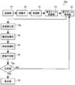
- the at least one sound speed setting unit includes a first sound speed setting unit that sets the sound speed of the inspection object used for delay time calculation in the data processing unit, and data is generated using the sound speed set by the first sound speed setting unit.
- the processing unit obtains the second element data, performs the phasing addition of the second element data to generate the sound ray signal, and the suitability of the sound ray signal obtained by the phasing addition unit.
- a first generation unit that generates an ultrasonic image based on the sound ray signal generated by the phasing addition unit, and the determination result of the first determination unit is NO
- the first sound speed setting unit newly sets another sound speed again, calculates the delay time again using the sound speed set again by the data processing unit, and sets the second sound speed based on the delay time calculated again.
- the element data of The sound ray signal is generated again using the element data until the determination result of the first determination unit based on the regenerated sound ray signal becomes appropriate, and the determination result of the first determination unit is appropriate.
- the image generation unit preferably generates an ultrasonic image based on the sound ray signal.
- the first sound speed setting unit preferably sets the sound speed to at least one point on the reception time for each element data.
- a second sound speed setting unit that obtains the optimum sound speed on the receiving side based on the second element data generated at this time, and the second sound speed
- the phasing addition unit that generates the sound ray signal by performing the phasing addition of the second element data using the optimum sound speed obtained by the setting unit, and the suitability of the sound ray signal obtained by the phasing addition unit.
- a second determination unit and when the determination result of the second determination unit is NO, the second sound speed setting unit obtains the optimum sound speed again based on the second element data, and phased
- the adder repeats the generation of the sound ray signal again using the optimum sound speed obtained again until the determination result of the second determination portion based on the regenerated sound ray signal becomes appropriate, and the second determination
- the image generation unit may generate an ultrasonic image based on the sound ray signal. Masui. Further, it is preferable that the second sound speed setting unit sets the sound speed to at least one point on the reception time for each element data.
- a third sound speed setting unit that obtains the optimum sound speed on the receiving side, and the phasing of the first element data using the optimum sound speed obtained by the third sound speed setting unit.
- a phasing / adding unit that performs addition to generate a sound ray signal
- a third determination unit that determines the suitability of the sound ray signal obtained by the phasing / addition unit.
- the third sound speed setting unit obtains the optimum sound speed again based on the first element data, and the phasing adder generates the sound ray signal again using the optimum sound speed obtained again.
- the third sound speed setting unit preferably sets the sound speed to at least one point on the reception time for each element data.
- the third sound speed setting unit is preferably the same as the second sound speed setting unit.
- the third determination unit is preferably the same as the second determination unit.
- the at least one sound speed setting unit includes a fourth sound speed setting unit that obtains the optimum sound speed on the reception side based on the second element data generated using the predetermined sound speed by the data processing unit, A phasing addition unit that generates a sound ray signal by performing phasing addition of the second element data using the optimum sound speed obtained by the fourth sound speed setting unit, and a sound obtained by the phasing addition unit.
- a determination result of the fourth determination unit and a fourth determination unit that determines the suitability of the line signal, and an image generation unit that generates an ultrasonic image based on the sound ray signal generated by the phasing addition unit.
- the data processing unit performs processing for generating the second element data again using the optimum sound speed obtained by the fourth sound speed setting unit, and the fourth sound speed setting unit generates again Based on the second element data thus obtained, the optimum sound speed is obtained again, and the phasing adder again
- the generation of the sound ray signal again using the determined optimum sound speed is repeated until the determination result of the fourth determination unit based on the regenerated sound ray signal becomes appropriate, and the determination result of the fourth determination unit is
- the image generation unit preferably generates an ultrasonic image based on the sound ray signal.
- the fourth sound speed setting unit preferably sets the sound speed to at least one point on the reception time for each element data.
- the fourth sound speed setting unit is preferably the same as the second sound speed setting unit and the third sound speed setting unit.
- the fourth determination unit is preferably the same as the second determination unit and the third determination unit.
- an ultrasonic inspection apparatus of the present invention is an ultrasonic inspection apparatus that inspects an inspection object using an ultrasonic beam, transmits the ultrasonic beam, and is an inspection object.
- a probe in which a plurality of elements are arranged to receive an ultrasonic echo reflected by an object and output an analog element signal corresponding to the received ultrasonic echo, and a plurality of elements are used for the probe , Transmitting the ultrasonic beam so as to form a predetermined transmission focal point a plurality of times, and corresponding to the transmission of the individual ultrasonic beams, the analog element signals output by the plurality of elements are transmitted.
- a receiving unit that performs predetermined processing, an A / D conversion of an analog element signal processed by the receiving unit to obtain first element data that is a digital element signal, and a plurality of first elements From the data, the first element data A data processing unit that generates second element data corresponding to any of the above, a first image generation unit that generates a first ultrasonic image based on the first element data, and a second element data A second image generation unit that generates a second ultrasonic image, a first ultrasonic image generated by the first image generation unit, and a second ultrasonic image generated by the second image generation unit.
- the image quality determination unit performs image quality determination based on any one of luminance value, contrast, and graininess, or a combination of two or more in the first ultrasonic image and the second ultrasonic image. It is preferable.
- the third image generation unit is configured as an ultrasonic image in which one of the first ultrasonic image and the second ultrasonic image is a target for ultrasonic inspection based on the determination result of the image quality determination unit. It is preferable to adopt.
- it further includes an area dividing unit that divides the first ultrasonic image and the second ultrasonic image into a plurality of areas, and the image quality determination unit includes the first ultrasonic image for each area divided by the area dividing unit.
- the image quality determination between the sound wave image and the second ultrasonic image is performed, and the third image generation unit performs the first ultrasonic image and the second ultrasonic image for each region based on the determination result of the image quality determination unit. It is preferable to select one of the two as an ultrasonic image of the corresponding region and create an ultrasonic image by combining the images selected for each region.
- the influence of the spread of the transmitted ultrasonic beam is obtained by superimposing element data acquired by transmission from two or more different elements.
- FIG. 5 is an explanatory diagram showing element data obtained respectively.
- (A) And (c) is explanatory drawing in the case of transmitting an actual ultrasonic beam from the element directly above the reflection point of the subject and the element not directly above, respectively, (b) and (d) It is explanatory drawing which shows the element data obtained, respectively.
- (A) And (b) is explanatory drawing explaining the distance of the transmission path
- (A), (b) and (c) and (d), (e) and (f) are respectively the element data obtained by a plurality of elements in the case of a true signal and the case of a ghost, their delay time and It is explanatory drawing which shows the superimposition state of element data, (g) And (h) is explanatory drawing which shows the superimposition state of the element data corresponding to a some element, respectively, and its result.
- (A) And (b) is a block diagram which shows notionally an example of the principal part of the ultrasonic inspection apparatus of Example 2 of this invention along a processing flow, respectively.
- FIG. 9 It is a block diagram which shows notionally an example of the principal part of the ultrasonic inspection apparatus of Example 3 of this invention along a process flow.
- A is a block diagram conceptually showing an example of the configuration of the sound speed correction unit of the ultrasonic inspection apparatus shown in FIG. 9, and
- (b) is a region-of-interest setting unit of the sound speed correction unit shown in (a).
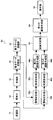
- FIG. 8 It is a block diagram which shows notionally one Example of a structure of the ultrasonic inspection apparatus of Example 8 of this invention. It is a block diagram which shows notionally an example of a structure of the data processing part of the ultrasonic inspection apparatus shown in FIG. It is a figure which shows element data and an element conceptually.
- (A) to (C) are diagrams for explaining phasing addition and superposition processing of the data processing unit shown in FIG.
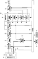
- FIG. 1 is a block diagram conceptually showing an embodiment of the configuration of the ultrasonic inspection apparatus of the present invention.
- an ultrasonic inspection apparatus 10 includes an ultrasonic probe 12, a transmission unit 14 and a reception unit 16 connected to the ultrasonic probe 12, an A / D conversion unit 18, and an element data storage unit 20.
- the ultrasonic probe 12 has a probe 36 used in a normal ultrasonic inspection apparatus.
- the probe 36 has a plurality of elements arranged in a one-dimensional or two-dimensional array, that is, ultrasonic transducers. These ultrasonic transducers transmit an ultrasonic beam to a subject in accordance with a drive signal supplied from the transmission unit 14 when an ultrasonic image of an object to be examined (hereinafter referred to as a subject) is captured. Receives ultrasonic echoes from the specimen and outputs a received signal.
- each of a predetermined number of ultrasonic transducers constituting a set of the plurality of ultrasonic transducers of the probe 36 generates each component of one ultrasonic beam, and a set of a predetermined number of ultrasonic transducers.
- the ultrasonic transducer generates one ultrasonic beam that is transmitted to the subject.
- Each ultrasonic transducer is, for example, a piezoelectric ceramic represented by PZT (lead zirconate titanate), a polymer piezoelectric element represented by PVDF (polyvinylidene fluoride), or PMN-PT (magnesium niobate / lead titanate). It is constituted by an element in which electrodes are formed at both ends of a piezoelectric body made of a piezoelectric single crystal or the like typified by a solid solution, that is, a vibrator. That is, the probe 36 can be referred to as a transducer array in which a plurality of transducers are arranged in a one-dimensional or two-dimensional array as a plurality of ultrasonic elements.
- PZT lead zirconate titanate
- PVDF polyvinylidene fluoride
- PMN-PT magnesium niobate / lead titanate
- each transducer When a pulsed or continuous wave voltage is applied to the electrodes of such a vibrator, the piezoelectric material expands and contracts, and pulse or continuous wave ultrasonic waves are generated from the respective vibrators, and the synthesis of these ultrasonic waves. As a result, an ultrasonic beam is formed.
- each transducer generates an electric signal by expanding and contracting by receiving propagating ultrasonic waves, and these electric signals are output as ultrasonic reception signals.
- the transmission unit 14 includes, for example, a plurality of pulsars, and according to the sound speed or the distribution of sound speeds set based on the transmission delay pattern selected according to the control signal from the control unit 30, one of the probes 36.
- a plurality of sets formed by adjusting the delay amount of each drive signal so that ultrasonic beam components transmitted from a predetermined number of ultrasonic transducers (hereinafter referred to as ultrasonic elements) form one ultrasonic beam.
- ultrasonic elements formed by adjusting the delay amount of each drive signal so that ultrasonic beam components transmitted from a predetermined number of ultrasonic transducers (hereinafter referred to as ultrasonic elements) form one ultrasonic beam.
- the receiving unit 16 receives, from the subject, an ultrasonic echo generated by the interaction between the ultrasonic beam and the subject by each ultrasonic element of the probe 36 in accordance with a control signal from the control unit 30. Then, the reception signal, that is, the analog element signal for each ultrasonic element is amplified and output, and the amplified analog element signal is supplied to the A / D converter 18.
- the element data storage unit 20 sequentially stores digital element data (hereinafter simply referred to as element data) output from the A / D conversion unit 18.
- the element data is data representing the relationship between the position (element position), reception time, and signal intensity, and includes phase information and amplitude information.
- the element data storage unit 20 associates information about the frame rate input from the control unit 30 (for example, parameters indicating the depth of the reflection position of the ultrasonic wave, the density of the scanning line, and the visual field width) with the digital element data. Store.
- the element data storage unit 20 inspects at least two or more target regions that overlap in a target region on two-dimensional or higher position coordinates in accordance with a control signal from the control unit 30, the two or more target regions
- Each of the two or more element data generated for each two or more target regions from the ultrasonic echo received by the receiving unit 16 is stored and held, and the element data stored and held in the element data storage unit 20 is Two or more element data including reception data for each reception time in each element received for each element data.
- the element data processing unit 22 is a feature of the present invention, and two or more generated for each of two or more target regions stored and held by the element data storage unit 20 based on control by the control unit 30.
- the element data (hereinafter referred to as unprocessed element data) are overlapped with each other over the reception time to generate post-overlay element data (hereinafter referred to as processed element data).
- the element data processing unit 22 is based on the control by the control unit 30, and among the element data stored in the element data storage unit 20, a central ultrasonic transducer (center element (center element)).
- the image generation unit 24 generates a sound ray signal (reception data) from the processed element data supplied from the element data processing unit 22 under the control of the control unit 30, and generates an ultrasonic image from the sound ray signal. Is.
- the image generation unit 24 includes a phasing addition unit 38, a detection processing unit 40, a DSC 42, an image creation unit 44, and an image memory 46.
- the phasing addition unit 38 selects one reception delay pattern from a plurality of reception delay patterns stored in advance according to the reception direction set in the control unit 30, and based on the selected reception delay pattern
- the reception focus processing is performed by adding the respective delays to the element data in accordance with the set sound speed or the distribution of sound speed.
- reception data sound ray signal
- the phasing addition unit 38 supplies the received data to the detection processing unit 40.
- the detection processing unit 40 corrects attenuation according to the distance according to the depth of the reflection position of the ultrasonic wave on the reception data generated by the phasing addition unit 38, and then performs envelope detection processing to perform detection.
- B-mode image data that is tomographic image information related to the tissue in the specimen is generated.
- a DSC (digital scan converter) 48 converts (raster conversion) the B-mode image data generated by the detection processing unit 40 into image data according to a normal television signal scanning method.
- the image creation unit 44 performs various necessary image processing such as gradation processing on the B-mode image data input from the DSC 42 to create B-mode image data for use in inspection and display, and then creates the created inspection. Or display B-mode image data is output to the display control unit 26 for display or stored in the image memory 46.
- the image memory 46 temporarily stores the inspection B-mode image data created by the image creation unit 44.
- the inspection B-mode image data stored in the image memory 46 is read to the display control unit 26 for display on the display unit 28 as necessary.
- the display control unit 26 causes the display unit 28 to display an ultrasonic image based on the inspection B-mode image signal subjected to the image processing by the image creation unit 44.
- the display unit 28 includes a display device such as an LCD, for example, and displays an ultrasonic image under the control of the display control unit 26.
- the control unit 30 controls each unit of the ultrasonic inspection apparatus 10 based on a command input from the operation unit 32 by the operator.
- the control unit 30 provides various information by the operator via the operation unit 32, in particular, information necessary for delay time calculation used in the phasing addition unit 38 of the element data processing unit 22 and the image generation unit 24, and
- the above-described various information input from the operation unit 32 is transmitted as necessary to the transmission unit 14, the reception unit 16, and the element.
- the data storage unit 20, the element data processing unit 22, the image generation unit 24, the display control unit 26, and the like are supplied.
- the operation unit 32 is for an operator to perform an input operation, and can be formed from a keyboard, a mouse, a trackball, a touch panel, and the like.
- the operation unit 32 is used by the operator for various types of information, in particular, a plurality of ultrasonic elements of the probe 36 of the probe 12 used for calculating the delay time described above, the sound speed of the examination target region of the subject, Provided with an input device for inputting and operating information regarding the focal position of the ultrasonic beam, the transmission aperture and the reception aperture of the probe 36, and information regarding element data processing such as the number of overlapping element data and the overlay processing method ing.
- the storage unit 34 includes various information input from the operation unit 32, in particular, information on the probe 12, the sound speed, the focal position, the transmission aperture, the reception aperture, and the like, the number of superimposing element data, the superposition processing method, and other elements.
- Information related to data processing, processing and operations of each unit controlled by the control unit 30 such as the transmission unit 14, the reception unit 16, the element data storage unit 20, the element data processing unit 22, the image generation unit 24, and the display control unit 26 Is stored in the hard disk, flexible disk, MO, MT, RAM, CD-ROM, DVD-ROM, etc. Media can be used.
- the element data processing unit 22, the phasing addition unit 38, the detection processing unit 40, the DSC 42, the image creation unit 44, and the display control unit 26 are composed of a CPU and an operation program for causing the CPU to perform various processes. However, they may be composed of digital circuits.
- the element data processing unit 22 includes a delay time calculation unit 48 and an overlay processing unit 50.
- the delay time calculation unit 48 examines the plurality of ultrasonic elements and the subject of the probe 36 of the probe 12 input from the operation unit 32 or input from the operation unit 32 and stored in the storage unit 34. Information on the sound velocity of the target region, the focal position of the ultrasonic beam, the transmission aperture and the reception aperture of the probe 36, etc. are acquired in advance, and an ultrasonic element (transmission) of the transmission aperture is formed and transmitted. Element) and the ultrasonic wave of the ultrasonic wave from the subject to receive ultrasonic echoes from the subject. Calculate the delay time.
- the overlay processing unit 50 relates to element data processing such as the number of element data to be superimposed and the overlay processing method, which are input from the operation unit 32 or input from the operation unit 32 and stored in the storage unit 34. Based on the information, two or more unprocessed element data generated for each of the two or more target regions stored and held by the element data storage unit 20 are read, and based on the delay times calculated by the delay time calculation unit 48, respectively. Two or more unprocessed element data are superimposed on the reception time, that is, by matching the time and the absolute position of the elements of the received probe to generate processed element data.
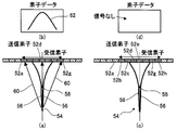
- an ultrasonic beam (hereinafter simply referred to as a transmission beam) is transmitted from a transmission ultrasonic element (hereinafter simply referred to as a transmission element) of the probe 36 of the ultrasonic probe 12 to the subject, and a mutual relationship with the subject is obtained.
- a transmission ultrasonic element hereinafter simply referred to as a transmission element
- element data it is obtained by the transmission beam from the transmitting element and the receiving element.
- ultrasonic elements 52a to 52g and 52b to 52h are used as receiving elements to receive ultrasonic echoes and obtain element data.
- elements 52a to 52g and 52b to 52h are used as receiving elements to receive ultrasonic echoes and obtain element data.
- the focal point 58 of the beam 56 is on a straight line connecting the element 52d and the reflection point 54. Since the transmission beam 56 is transmitted to the reflection point 54, an ultrasonic echo reflected from the reflection point 54 is generated. The ultrasonic echoes from the reflection point 54 are received by the receiving elements 52a to 52g through the receiving path 60 spreading at a predetermined angle, and the element data 62 as shown in FIG. 3B is obtained by the receiving elements 52a to 52g. Will be.
- the center of the transmitting element is shifted by one element with respect to the reflection point 54 in the direction of the element (right direction in the figure), and just above the reflection point 54.
- the transmission direction of the transmission beam 56 that is, the transmission element 52e and the focal point 58 are received. Therefore, the transmission beam 56 is not transmitted to the reflection point 54. For this reason, the ultrasonic echo reflected from the reflection point 54 is not generated, and the reception elements 52b to 52h do not receive the ultrasonic echo. Therefore, as shown in FIG. (The signal strength of the element data becomes “0”).
- the actual transmission beam 64 is wider than the element spacing.
- the transmission beam 56 is transmitted as in the case of FIG. Is wide, the focal point 58 is on a straight line connecting the element 52d and the reflection point 54, and the transmission beam 64 is reflected by the reflection point 54, and an ultrasonic echo is generated.
- the ultrasonic echo from the reflection point 54 is received by the receiving elements 52a to 52g through the receiving path 60 spreading to a predetermined angle, and is received by the receiving elements 52a to 52g.
- True element data 66 as shown in FIG. 4B is obtained.
- the center of the transmitting element is shifted by one element with respect to the reflection point 54 in the element direction (right direction in the figure).
- the transmission beam 64 is transmitted using the element 52e adjacent to the element 52d immediately above the reflection point 54 as a transmission element and the ultrasonic echoes are received by the reception elements 52b to 52h, the transmission beam 64 is wide. Even if the reflection point 54 does not exist in the transmission direction, that is, on the straight line connecting the transmission element 52e and the focal point 58, the transmission beam 64 is transmitted to the reflection point 54.
- an ultrasonic echo that does not exist originally that is, a so-called ghost reflection signal is generated from the reflection point 54
- the ghost reflection signal from the reflection point 54 passes through the reception path 60 that spreads to a predetermined angle to the reception elements 52b to 52h.
- the ghost element data 68 as shown in FIG. 4D is obtained by the reception elements 52b to 52h.
- Such ghost element data 68 causes a decrease in the accuracy of the ultrasonic image generated from the element data.
- the element data processing unit 22 calculates a delay time corresponding to the element data by the delay time calculation unit 48, and the overlay processing unit 49 determines that the two or more element data correspond to the delay time and the absolute position of the element. By superimposing them, the true element data is emphasized, and the processed element data, which is highly accurate element data in which the ghost element data is attenuated, is generated.
- the transmission beam 64 shown in FIG. 4C is transmitted from the transmission element 52e via the focal point 58 to the reflection point 54, and the ghost reflection signal is received from the reflection point 54 to each of the reception elements 52b to 52h.
- the sum (propagation distance) with the path is such that the transmission beam 64 shown in FIG. 4A reaches the reflection point 54 from the transmission element 52d via the focal point 58 and the true reflected ultrasonic echo is the reflection point 54. 4 is longer than the sum (propagation distance) with the receiving path from the receiving elements 52a to 52g to the ghost element data 68 as shown in FIG. 4 (d). There will be a delay with respect to the element data 66.
- the delay time calculation unit 48 of the element data processing unit 22 of the present invention the time difference between the ghost element data and the true element data, that is, the delay time is the transmission element, the focal point of the ultrasonic beam, the reflection point of the subject, and Calculated from the geometry of the receiving elements. Therefore, the calculation of the delay time requires information such as the shape of the ultrasonic probe 12 (element spacing, linear, convex, etc.), the sound velocity of the examination region of the subject, the focal position, the transmission aperture, the reception aperture, etc.
- the delay time calculation unit 48 obtains these pieces of information input by the operation unit 32 or stored in the storage unit 34 and calculates the delay time.
- the delay time is calculated from, for example, the transmission element, the focal point of the ultrasonic beam, the reflection point of the subject, and the geometric arrangement of the reception element, the transmission path of the transmission beam from the transmission element to the reflection point through the focal point, and It can be calculated from the difference between the total length (propagation distance) of the reception path of the true reflected ultrasonic echo or ghost reflected signal from the reflection point to the receiving element and the propagation time calculated by the sound speed.
- the lengths of the transmission path and the reception path of the transmission beam in the case of a true reflected ultrasonic echo and a ghost reflection signal are obtained. be able to.
- the transmitting element 52d and the receiving element 52d coincide with each other, and the focal point 58 and the reflection point 54 are directly below.
- the position of the element 52d directly above the reflection point 54 is the coordinate (x0, 0) on the xy two-dimensional coordinate, the element interval is Le, the position of the focal point 58 is the coordinate (x0, df), the reflection point
- the position of 54 is the coordinate (x0, z)
- the position of the transmitting element 52d is also the same coordinate (x0, 0) as the element 52d immediately above the reflecting point 54, and the reflecting point 54 passes through the focal point 58 from the transmitting element 52d.
- the position of the transmission element 52e is one element lateral to the reflection point 54 as compared to the case of FIG. Rightward)
- the focal point 58 is arranged directly below the transmitting element 52e, but the reflection point 54 is arranged immediately below the receiving element 52d, and the position of the receiving element 52d immediately above the reflection point 54 is As in the case of FIG.
- a value obtained by dividing the ultrasonic propagation distance Lua by the sum of the distance Lta of the transmission path 61 and the distance Lra of the reception path 60 obtained by the geometric arrangement shown in FIG. The value obtained by dividing the ultrasonic propagation distance Lub by the sum of the distance Ltb of the transmission path 61 and the distance Lrb of the reception path 60 obtained by the geometric arrangement shown in FIG. Signal propagation time.
- the delay time is calculated by calculating the x coordinate of the reflection point 54 and the transmission element 52 (52e) from the propagation time of the true ultrasonic echo when the reflection point 54 and the x coordinate of the transmission element 52 (52d) match.
- the delay time is obtained from the difference in propagation time of the reflected signal of the ghost when it is shifted by one element interval.
- the transmission path 61 is a model passing through the focal point 58.
- the present invention is not limited to this, and for example, via the focal point 58.
- a route that directly reaches the reflection point 54 may be used.
- the geometric model of FIG. 5A and FIG. 5B is a case of a linear probe, not only this but the other geometrical calculation can be performed from the shape of a probe.
- a geometric model can be set from the radius of the probe and the angle between the elements, and the calculation can be performed in the same way.
- a geometric model (not shown) that considers information such as the transmission angle is used, and the element data of the true ultrasonic echo and its surroundings are determined from the positional relationship between the transmission element and the reflection point. The delay time of the ghost element data can be calculated.
- the delay time is not limited to the method of calculating the delay time using the geometric model, and the delay time is obtained for each measurement condition from the measurement result obtained by measuring the high-intensity reflection point according to the measurement condition of the apparatus in advance. By storing in the apparatus, the delay time of the same measurement condition may be read out.
- FIG. 5C shows the element data 66 of the true signal at the center and the element data 68 of the ghost around the true signal
- FIG. 5D shows the element data 66 obtained from the above geometric calculation.
- An example of the delay time of the ghost element data 68 is shown. It is shown that the element data 68 of the ghost signal is symmetrically delayed with respect to the element data 66 of the true signal. In this way, the delay time calculated by the delay time calculation unit 48 of the element data processing unit 22 can also be used for delay correction in the phasing addition unit 38.
- the element data obtained by transmitting an ultrasonic beam having a certain element of interest as the central element is different from the central element, and the ultrasonic beam
- the element data obtained by transmitting at least a part of the overlapping ultrasonic beam is overlapped with the reception time of the ultrasonic echo and the position of the element so as to superimpose the processed element data (second element) of the element of interest.
- Data) (reconstruct the element data of the element of interest).
- a reflection point 54 indicates the position (element data output position) of a certain sampling point located directly below the target element (same position in the azimuth direction / on the straight line connecting the target element and the focal point).
- the transmission / reception path to the sampling point immediately below the target element in the transmission / reception of the target element is regarded as the transmission / reception path of the true element data, and the same sampling point in the transmission / reception of ultrasonic waves (transmission / reception from peripheral elements) with different central elements
- the transmission / reception route to the ghost is regarded as a ghost transmission / reception route
- a delay time is calculated from the difference between the two transmission routes, and the element data is timed using this delay time to perform superposition.
- delay time is calculated in the same way, element data is superimposed, and processed element data of each element is generated. To do. At that time, it is preferable to set a plurality of sampling points also in the depth direction (y direction) on the same line. Here, actually, even if the position of the sampling point (reflection point) is shifted in the azimuth direction (x direction), the length of the reception path (reception path distance Lrb) does not change. Therefore, for each element of interest, a delay time with element data by transmission / reception with different central elements may be calculated for each sampling point in the depth direction (y direction). In this superposition process, it is not necessary to know which element data is the true element data.
- the superimposition processing unit 50 of the element data processing unit 22 of the present invention the element data of the true ultrasonic echo and the surrounding ghost elements using the delay time thus calculated by the delay time calculation unit 48. Perform data overlay processing.
- information on the number of superposition element data and the superposition processing method at the time of superposition is necessary, but these may be input in advance by the operation unit 32. Alternatively, it may be stored in the storage unit 34.
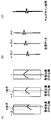
- FIGS. 6A to 6H show a specific example of superposition processing performed by the superposition processing unit 50 when the number of element data is five and the number of superposition element data is three.
- FIG. 6A shows five element data arranged side by side, and shows a state in which an ultrasonic beam is transmitted and a reflected signal is received for each element data.
- the horizontal axis of each element data represents a receiving element, and the respective element data are displayed with the center element at the time of transmission of the ultrasonic beam as the center.
- the vertical axis represents the reception time.
- the middle element data there is a reflection point directly below the element at the center of the element data (element at the center of the receiving element), that is, the element at the center at the time of transmission (transmitting element). A reflection signal from the reflection point is received. That is, the reflected signal is a true signal, and the element data in the middle represents the true signal.
- the transmission element of the middle element data A reflected signal, i.e., a ghost, which is generated when an ultrasonic beam hits a reflection point existing directly below, is reflected. Since the propagation time of the ultrasonic wave to the reflection point becomes longer as the ghost is away from the true signal, the reception time is delayed as compared with the true signal.
- the position of the receiving element where the reflected signal from the reflecting point is first received is the element immediately above the reflecting point, but the horizontal axis of the element data is centered on the central element when transmitting the ultrasonic beam.
- the central element is shifted by one element for each element data
- the absolute position of the element is shifted by one element in each element data. That is, in the middle element data, the receiving element from which the reflected signal from the reflection point is received first is the middle element, but the element data on both sides is shifted by one element from the middle element data.
- the element data is shifted one element to the left, and the left element data is shifted one element to the right. Further, the element data at both ends are shifted by two elements from the middle element data, the leftmost element data is shifted by two elements to the left, and the leftmost element data is shifted by two elements to the right.
- the ghost signal is not only delayed in reception time with respect to the true signal, but also deviated from the direction of the receiving element.
- FIG. 6B shows an example of the delay time of the reception time for the middle element data among the five element data shown in FIG.
- the overlay processing unit 50 uses the delay time shown in FIG. 6B to set the element data of the element of interest as the element data of the element of interest.
- the delay time is corrected by three element data, and each element data is horizontally shifted by one element on both sides in the illustrated example in accordance with the difference in element position from the element of interest (difference in the position of the central element).
- the unprocessed element data corresponding to the three element data is overlapped by shifting in the direction, that is, in phase, and obtained as one overlapped element data of the element data of the element of interest.
- FIG. 6C shows element data that has been subjected to the superimposition processing of the element data of the element of interest obtained in this way. Since the element data of the target element shown in FIG. 6A is element data of a true signal, delay time correction and lateral shift are performed on unprocessed element data of adjacent element data on both sides of the element data of the target element.
- phase matching is performed, as shown in FIG. 6C, the unprocessed element data of the adjacent element data and the unprocessed element data of the target element overlap each other at the high luminance position because the phases match. Therefore, when these element data are added, for example, the element data value shows a large value (high luminance value), and for example, even if an average value is obtained by averaging, an emphasized value (high luminance value) is shown.
- FIG. 6D shows the same element data as FIG. 6A, but shows an example in which the element data on the left side of the middle element data, that is, the ghost is the element data of the element of interest.
- FIG. 6E is the same as FIG. 6B, and shows an example of the delay time of the reception time for the middle element data among the five element data shown in FIG. 6A. That is, since FIG. 6A and FIG. 6D are the same element data, the delay time of the reception time for the middle element data among the five element data shown in FIG. 6D is the same.
- the delay time shown in FIG. 6E that is, the same as FIG.
- the delay time is corrected by three element data, and each element data is shifted laterally by one element on both sides in the illustrated example in accordance with the difference in element position with respect to the element of interest (difference in the position of the central element).
- the unprocessed element data corresponding to the three element data is superimposed and obtained as one overlapped element data of the element data of the element of interest.
- FIG. 6F shows element data obtained by superimposing the element data of the element of interest obtained in this way. Since the element data of the target element shown in FIG. 6D is ghost element data, the delay time correction and the lateral shift are performed on the unprocessed element data of the adjacent element data on both sides of the element data of the target element. As shown in FIG. 6F, the unprocessed element data of the adjacent element data and the unprocessed element data of the target element do not overlap because the phases are not matched. For this reason, even if these three element data are added, for example, since the phases are not matched, signals that are inverted in phase cancel each other out, so the added value does not increase. When the average value is obtained, a small value is shown.
- the same delay time correction and lateral shift are performed as the element data of the element of interest.
- the overlapping state of three adjacent element data for each of the five element data in the illustrated example is shown in FIG. FIG. 6H shows a result obtained by performing, for example, an addition process or an average process as an overlay process on these items.
- the element data of the true signal has a high luminance value.
- the element data of the ghost adds or averages the element data whose phases are not matched with each other, so they cancel each other out. Therefore, the superposed processed element data of the ghost is smaller than the superposed processed element data having a high luminance value, which is the element data of the true signal, and is smaller than the element data of the true signal.
- the influence of the ghost element data can be reduced, or the influence can be reduced to the extent that the influence can be ignored. Therefore, by performing phasing addition and detection processing on the processed element data, generating reception data and generating an ultrasonic image, similarly, the influence of ghost is eliminated, that is, at all points on the sound ray. Since an ultrasonic image can be generated with element data equal to the focal point, it is possible to generate a high-quality ultrasonic image with high brightness and excellent sharpness.
- the generation of processed element data is also referred to as multiline processing.
- the central element is an element at the center in the azimuth direction when the numerical aperture for transmission (the number of elements for transmitting ultrasonic waves) is an odd number.
- the numerical aperture is an even number
- one of the central elements in the azimuth direction is set as the central element, or the central element is assumed to be in the middle of the azimuth direction. That is, when the numerical aperture is an even number, the calculation may be performed assuming that the focal point is on the middle line of the aperture.
- the superposition processing method in the superposition processing unit 50 is not simply an addition, but may be an average value or a median value, or may be added after being multiplied (weighted) by multiplying coefficients. Good. Note that taking an average value or median value is thought to correspond to applying an averaging filter or median filter at the element data level, but is performed by normal image processing instead of the averaging filter or median filter. An inverse filter or the like may also be applied. Alternatively, the element data to be superimposed are compared, and if they are similar, the maximum value is taken, if not, the average value is taken, and if there is a distribution bias, the intermediate value is taken. The overlay process may be changed based on the feature amount of each element data to be superimposed.
- the number of element data to be superimposed on the element data of the element of interest is not limited to two in the illustrated example, and may be one or three or more. That is, the number of element data to be superimposed on the element data of the element of interest may be appropriately set according to the required processing speed (frame rate or the like), image quality, and the like. Further, it is desirable that the number of element data to be superimposed is matched to the extent of the beam width of the ultrasonic beam. Therefore, when the beam width changes depending on the depth, the number of overlapping element data may be changed depending on the depth. Further, since the beam width depends on the transmission numerical aperture, the number of overlapping element data may be changed according to the transmission numerical aperture.
- the number of overlapping element data may be changed based on a feature quantity such as a luminance value of an image, or based on the result of analyzing the waveform of element data and evaluating the correlation and coherence between the element data.
- the number of overlapping element data may be changed, or the optimum number of overlapping element data may be selected from images created by changing the number of overlapping element data.
- the number of element data to be superimposed is not limited to change according to the depth, but the depth of transmission focus, the transmission numerical aperture, etc. according to the spatial depth of the overlapping position (sampling point).
- the multi-line processing may be performed using the first element data obtained by transmitting the ultrasonic beam under the changed transmission condition.
- multiline processing is performed using first element data obtained by setting the transmission focal point at a position corresponding to the depth of the sampling point so that the sampling point and the focal point have a predetermined distance. Thereby, the accuracy of multiline processing can be made uniform regardless of the depth of the sampling point.
- an ultrasonic beam forming a transmission focal point having a different depth on the same transmission line is transmitted to obtain a plurality of first element data corresponding to the same transmission line, and element data
- the processing unit 22 may perform multiline processing using the first element data having the same focal depth with different transmission lines for each transmission focal depth.
- the delay time may be calculated based on the depth of the transmission focus (element data reception time).
- the processed element data of the element data of the element of interest is generated, the present invention is not limited to this.
- the processed element data may be generated by superimposing element data obtained by transmitting a plurality of ultrasonic beams having different transmission directions (angles) with the same central element.
- which element data obtained by transmission of the ultrasonic beam to generate processed element data depends on the examination site and the probe.
- Processed element data may be generated.
- the signal phase matches in the element data of the true signal, but the signal phase does not match in the ghost.
- signals of various phases are mutually connected. Cancel each other and the signal becomes weaker.
- the true signal remains as effective element data having a valid value, for example, high luminance
- the ghost signal can be obtained as element data having a reduced value, for example, low luminance.
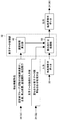
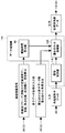
- FIG. 7 is a block diagram illustrating a main part of the ultrasonic inspection apparatus according to the first embodiment illustrated in FIG. 1 along a processing flow.
- the probe 36 is driven according to the drive signal supplied from the transmitter 14 as shown in FIG.
- the ultrasonic beam is transmitted from the probe, the probe 36 receives the ultrasonic echo from the subject, and outputs an analog element signal as a reception signal.
- the receiving unit 16 amplifies the analog element signal and supplies it to the A / D conversion unit 18, and the A / D conversion unit 18 converts the analog element signal into digital element data and supplies it to the element data storage unit 20. Keep memorized.
- the element data processing unit 22 delays the unprocessed element data of the peripheral ghost signal with respect to the unprocessed element data of the true signal (for example, FIG. 6B, FIG. 6 (e), both of which are the same)), the geometrical arrangement of the transmitting element, the focal point, the reflection point, and the receiving element, and the speed of sound of the examination target region of the subject input and set in advance. (E.g., using the geometric model of FIG. 5).
- the element data processing unit 22 reads unprocessed element data from the element data storage unit 20, sets the element data to be processed as element data of the element of interest, and calculates the delay time in the overlay processing unit 50 (FIG. 2). Using the delay time calculated by the unit 48, the element data of the element of interest and the surrounding unprocessed element data are phase-matched to obtain processed element data. As a result, enhanced processed element data is obtained for unprocessed element data including a true signal, and attenuated processed element data is determined for ghost unprocessed element data. The element data processing unit 22 supplies the processed element data thus obtained to the phasing addition unit 38 of the image generation unit 24.
- the phasing addition unit 38 of the image generation unit 24 performs reception focus processing on the element data to generate reception data (sound ray signal) and supplies it to the detection processing unit 40.
- the detection processing unit 40 processes the sound ray signal and generates a B-mode image signal.
- the DSC 42 performs raster conversion on the B-mode image signal, and the image creation unit 44 performs image processing to generate an ultrasonic image.
- the generated ultrasonic image is stored in the image memory 46, and the ultrasonic image is displayed on the display unit 28 by the display control unit 26.
- the ultrasonic inspection apparatus 10 creates an ultrasonic image using the processed element data in which the ghost signal is attenuated by the element data processing unit 22 and the true signal is emphasized. Therefore, without using an ultrasonic probe dedicated to wide beam transmission, and with a frame rate that is the same as before, high resolution that does not depend on the width of the transmission beam, high SN ratio, and sharpness with optimal spatial resolution An ultrasonic image can be obtained.
- the ultrasonic inspection apparatus according to the first embodiment of the present invention is basically configured as described above.
- the ultrasonic inspection apparatus 10 it is necessary when calculating the delay time in the delay time calculation unit 48 of the element data processing unit 22 and when calculating the delay time used in the phasing addition unit 38.
- the speed of sound in the test object that is, the test target area of the subject is given, but the present invention is not limited to this, and when the sound speed in the test object is not known, as shown below In the ultrasonic inspection apparatus, an optimum sound speed may be set.
- FIGS. 8A and 8B are block diagrams conceptually showing an example of a main part of the ultrasonic inspection apparatus according to the second embodiment of the present invention along the processing flow.
- the ultrasonic inspection apparatuses 70a and 70b shown in FIGS. 8A and 8B include the ultrasonic inspection apparatus 10 shown in FIGS. 1 and 7, the determination units 72a and 72b, and the sound speed change unit 74. Except for the differences, the components have exactly the same configuration, so the same components are denoted by the same reference numerals, and detailed description thereof is omitted.
- FIG. 8A shows the main part of the ultrasonic inspection apparatus 70a along the processing flow, as in FIG.
- the ultrasonic inspection apparatus 70a includes a transmission unit 14, a probe 36, a reception unit 16, an element data storage unit 20, an element data processing unit 22, and a phasing addition.
- the processing in the probe 36, the transmission unit 14, the reception unit 16, and the element data storage unit 20, and the processing in the element data processing unit 22, the phasing addition unit 38, the detection processing unit 40, and the image creation unit 44 Since the first processing is performed in the same manner as the ultrasonic inspection apparatus 10 shown in FIGS. 1 and 7, the description thereof is omitted.
- the element data processing unit 22 processes the element data using the preset initial value of the sound velocity, and then sends the processed element data to the phasing addition unit 38, so that the phasing addition unit 38 generates a sound ray signal (reception data) by performing reception focus processing, that is, phasing addition, using an appropriate sound speed value, for example, a sound speed value close to a living body, and the detection processing unit 40 generates
- reception focus processing that is, phasing addition
- an appropriate sound speed value for example, a sound speed value close to a living body
- the detection processing unit 40 generates
- the detected sound ray signal is subjected to detection processing to generate a B-mode image signal, and the image creating unit 44 performs image processing on the generated B-mode image signal to generate an ultrasonic image.
- the determination unit 72a is provided between the image creation unit 44 and the display unit 28, and uses, for example, an ultrasonic image created by the image creation unit 44, based on the created ultrasound image.
- the determination is performed based on the image quality index such as the luminance value, sharpness of the sound wave image, and the sharpness of the luminance value, the degree of convergence of the sound speed, and the like. For example, when the image quality index such as the luminance value, sharpness, and sharpness of the luminance value is higher than a predetermined value, preferably the highest, or the sound speed has converged within a predetermined range. Sometimes it is determined to be good or good (OK), otherwise it is determined to be negative (NG). If the determination unit 72a determines OK, the ultrasonic image created by the image creation unit 44 is sent to the display unit 28 and displayed on the display screen.
- the image quality index such as the luminance value, sharpness of the sound wave image, and the sharpness of the luminance value, the degree of convergence of the sound speed, and the like.
- the sound speed changing unit 74 is for setting an optimum sound speed when the sound speed in the inspection object necessary for delay time calculation in the delay time calculating unit 48 of the element data processing unit 22 is not known. From the initial value of the set sound speed, the sound speed value that has been changed first is changed to a new sound speed value for the second and subsequent times.
- the sound speed value may be changed by any method as long as it can obtain an optimal sound speed value at which the determination by the determination unit 72a is OK. It is preferable to reduce it.
- the sound speed value may be changed sequentially at predetermined speed intervals over a predetermined sound speed range.
- predetermined steps from 1400 m / s to 1 m / s to 50 m / s, for example, It can be changed sequentially up to 1700 m / s in steps of 10 m / s.
- the sound speed changing unit 74 changes to a new sound speed value
- the sound speed changing unit 74 returns to the element data processing unit 22 and the delay time calculation unit 48 of the element data processing unit 22 performs a new sound speed as the second and subsequent processing. Recalculate the delay time using the value.
- the overlay processing unit 50 performs overlay processing on two or more unprocessed element data using the delay time calculated by the delay time calculation unit 48 to obtain processed element data.
- the phasing / adding unit 38 newly changes the processed element data obtained by the element data processing unit 22 by the sound speed changing unit 74.
- a reception focus process is performed to generate a sound ray signal.
- the detection process unit 40 performs the detection process
- the image creation unit 44 performs the image process
- the ultrasonic image And the determination by the determination unit 72a.
- the determination of the determination unit 72 a is OK, the ultrasonic image created by the image creation unit 44 is displayed on the display unit 28.
- the determination of the determination unit 72a is NG, the determination is OK, that is, the sound speed change unit 74 changes to a new sound speed value, and the element data processing unit 22 delays until the optimum sound speed is set.
- the determination of the determination unit 72a is OK. If not, the sound speed value that is closest to the criterion may be adopted as the optimum sound speed.
- the method of changing the sound speed value and the method of setting the optimum sound speed by the sound speed changing unit 74 are not particularly limited in the present invention, and as described above, the sound speed value is sequentially changed at predetermined intervals within a predetermined sound speed range,
- the determination may be performed by the determination unit 72a each time the above-described processes are performed using the changed sound speed value, and the sound speed value is changed comprehensively at predetermined intervals throughout the predetermined sound speed range.
- the determination unit 72a may perform the determination after performing the above-described processes using all the sound speed values in the entire range of the predetermined sound speed range. However, the change of the sound speed value and the setting of the optimum sound speed are exploratoryly performed. It may be what you do.
- the initial value of the set sound speed is started from a value as close to the living body as possible, and for example, when the sound speed value is changed to the plus side, the image quality such as the sharpness of the image as the determination result If the index increases, repeat until the image quality index, such as sharpness, decreases further and decreases, or the image quality index, such as sharpness, decreases as a result of the judgment when the sound speed value is first changed to the negative side. If this is the case, change the next sound speed value from the comparison with the previous sound speed value, such as changing it to the plus side, to converge the sound speed value to the predetermined sound speed value, and use the converged predetermined sound speed value as the optimal sound speed. May be set.
- the area for setting the sound speed value is not particularly limited, and the entire subject and the entire inspection target area are set as the same sound speed value.
- the subject or the inspection target area may be divided into minute areas, and the sound speed value may be set for each minute area, or the sound speed value may be set for each pixel.
- a sound speed value may be set in the attention area of the subject or the inspection target area, and the sound speed value set in the attention area may be used as the optimum sound speed. Even in such a case, the sound speed value used for the calculation of the delay time may be the sound speed value at the position of the reflection point to be calculated.
- the determination unit 72a is provided between the image creation unit 44 and the display unit 28.
- the determination unit 72b may be provided between the phasing addition unit 38 and the detection processing unit 40 as in the ultrasonic inspection apparatus 70b shown in FIG.
- the processing in the probe 36, the transmission unit 14, the reception unit 16, and the element data storage unit 20 the detection processing unit 40, the image creation unit 44, and the display
- the processing in the unit 28 and the first processing in the element data processing unit 22 and the phasing addition unit 38 are performed in the same manner as in the ultrasonic inspection apparatus 70a shown in FIG. .
- the determination unit 72b is provided between the phasing addition unit 38 and the detection processing unit 40, and based on the sound ray signal generated by performing the reception focus processing in the phasing addition unit 38, for example, a sound
- the determination is made based on the image brightness index, the sharpness, the sharpness of the brightness value, and the like, the degree of convergence of the sound speed, and the like obtained from the line signal.
- the determination unit 72b is, for example, when the image quality index such as the luminance value, sharpness, or sharpness of the luminance value is higher than a predetermined value, preferably the highest, Is determined to be OK when the image has converged within the predetermined range, and NG is determined when the image quality index such as the luminance value and the sharpness has not reached the predetermined value or the highest value, or when the sound speed has not converged within the predetermined range. judge. If the determination unit 72b determines OK, the detection processing by the detection processing unit 40, the creation of an ultrasonic image by the image creation unit 44, and the display unit for the sound ray signal generated by the phasing addition unit 38 The ultrasonic image is displayed by 28.
- a predetermined value preferably the highest
- Is determined to be OK when the image has converged within the predetermined range
- NG is determined when the image quality index such as the luminance value and the sharpness has not reached the predetermined value or the highest value, or when the sound speed has not converge
- the process proceeds to the second and subsequent processes, the sound speed change unit 74 changes to a new sound speed value, returns to the element data processing unit 22, and the element data processing unit 22
- the delay time calculation unit 48 recalculates the delay time using the new sound speed value changed by the sound speed change unit 74.
- the overlay processing unit 50 performs overlay processing on two or more unprocessed element data using the delay time calculated using the new sound velocity value to obtain processed element data.
- the phasing / adding unit 38 changes the processed element data obtained by the element data processing unit 22 to the new speed changed by the sound speed changing unit 74.
- reception focus processing is performed to generate a sound ray signal (reception data), and in the determination unit 72b, based on the sound ray signal generated by the phasing addition unit 38 as in the first processing. Make a decision.
- each process by the sound speed changing unit 74, the element data processing unit 22, the phasing addition unit 38, and the determination unit 72b is repeated until the determination of the determination unit 72b becomes OK.
- an ultrasonic image is displayed on the display unit 28 through each process of the detection processing unit 40 and the image creation unit 44.
- the ultrasonic inspection apparatuses 70a and 70b according to the second embodiment of the present invention use the processed element data in which the ghost signal is attenuated by the element data processing unit 22 and the true signal is emphasized. Therefore, without using an ultrasonic probe dedicated to wide beam transmission, and with the same frame rate as before, high resolution that does not depend on the width of the transmission beam, high SN ratio, and optimal spatial resolution A sharp ultrasonic image can be obtained.
- the ultrasonic inspection apparatus according to the second embodiment of the present invention is basically configured as described above.
- the ultrasonic image generated by the image generation unit 44 is used.
- the ultrasonic image generated immediately or through the detection processing of the detection processing unit 40 and the image processing of the image generation unit 44 is displayed on the display unit 28.
- the present invention is not limited to this, and the determination unit After the determination result is OK, the optimum sound speed on the receiving side is obtained, and an ultrasonic image is created by performing reception focus processing (phased addition processing), detection processing, and image processing using the obtained optimum sound speed. May be displayed.
- FIGS. 9 and 12 are block diagrams conceptually showing an example of a main part of the ultrasonic inspection apparatus according to the third embodiment of the present invention along the processing flow.
- FIG. 10A is a block diagram conceptually showing an example of the configuration of the sound speed correction unit of the ultrasonic inspection apparatus shown in FIG.
- FIG. 10B is a diagram schematically illustrating an example of an ultrasound image in which a region of interest is set by the region-of-interest setting unit of the sound speed correction unit illustrated in FIG.
- FIG. 11 is a block diagram showing details of an example of the optimum sound speed calculation unit of the sound speed correction unit shown in FIG.
- the ultrasonic inspection apparatuses 70c and 70d shown in FIGS. 9 and 12 are respectively provided in the subsequent stages of the ultrasonic inspection apparatuses 70a and 70b and the determination units 72a and 72b shown in FIGS. 8 (a) and 8 (b), respectively.
- Sound speed correction units 76 and 76a are provided, and reception focus processing (phasing addition processing), detection processing, image processing, and ultrasonic image display are performed at the optimum sound speed set by the sound speed correction units 76 and 76a. Except for the differences, the components have exactly the same configuration, and thus the same components are denoted by the same reference numerals, and detailed description thereof is omitted.
- FIG. 9 is a block diagram showing the main part of the ultrasonic inspection apparatus 70c along the processing flow, as in FIG. 8A.
- the ultrasonic inspection apparatus 70 c includes a transmission unit 14, a probe 36, a reception unit 16, an element data storage unit 20, an element data processing unit 22, and a phasing addition unit 38.
- the processing in the detection processing unit 40, the image creation unit 44, the determination unit 72a, and the sound speed change unit 74 is performed in the same manner as the ultrasonic inspection apparatus 70a shown in FIG.
- the sound speed correction unit 76 is provided between the determination unit 72a and the phasing addition unit 38a.
- the receiving side optimum sound speed used in the phasing addition unit 38a that is, the examination target region of the subject, and therefore its The sound speed most suitable for the sound wave image is obtained.
- the sound speed correction unit 76 changes the entire predetermined sound speed range where the set sound speed v is estimated as the sound speed in the inspection target region at predetermined sound speed intervals, and specifically, for example, when a living body such as a human body is targeted.
- the optimum sound speed is comprehensively obtained based on the image quality index such as the sharpness and the convergence degree of the sound speed.
- a sound speed correction method by such a sound speed correction unit 76 for example, a sound speed correction method disclosed in Japanese Patent Application Laid-Open No. 2011-92686 can be used. In the sound speed correction method disclosed in this publication, it is necessary to establish a transmission focus for each region of interest.
- element data that can achieve transmission focus at any depth is obtained by the overlay processing of the overlay processing unit of the element data processing unit 22. There is no need to set the send focus to.
- the transmission focus may be set for each region of interest in accordance with the sound speed correction method disclosed in this publication.
- the sound speed correction unit 76 changes the set sound speed v in the inspection target region and changes the element data storage unit based on the set speed v at each set speed v as shown in FIG.
- the optimum sound speed calculation unit 80 using element data such as unprocessed element data supplied from 20 directly or through the element data processing unit 22 and processed element data supplied from the element data processing unit 22.
- the phasing / adding unit 38d performs reception focus processing to perform phasing addition to generate a sound ray signal, and an ultrasonic image is formed from the sound ray signal in the image creation unit 44d, and inspection at each set sound velocity v is performed.
- An image quality index such as a luminance value and sharpness of an image in the target area is calculated.
- the comparison determination unit 86 compares the image quality index such as the brightness value and sharpness of the image at each set sound speed v, and determines the set sound speed v having the highest image quality index value such as the obtained brightness value and sharpness, for example. Then, the determined set sound speed v is set in the sound speed setting unit 88 as an optimum sound speed value (optimum sound speed value). That is, in the sound speed correction unit 76, similarly to the sound speed change unit 74, the change of the sound speed value and the setting of the optimum sound speed may be performed exhaustively or in an exploratory manner.
- the area in which the sound speed value is set is not particularly limited, and the entire subject and the entire inspection target area are set as the same sound speed value.
- the subject or the inspection target area may be divided into minute areas, and the sound speed value may be set for each minute area, or the sound speed value may be set for each pixel.
- a sound speed value may be set in a region of interest of a subject or an inspection target region, and the sound speed value set in the region of interest may be used as the optimum sound speed. Even in such a case, the sound speed value used for the calculation of the delay time may be the sound speed value at the position of the reflection point to be calculated.
- the sound speed correction unit 76 may set the sound speed value used by the phasing addition unit 38 as the optimum sound speed as it is set by the sound speed changing unit 74 when the determination result by the determination unit 72a is OK.
- the sound speed correction unit 76 after the determination result in the determination unit 72a becomes OK, the sound speed correction unit 76 finally sets the optimum sound speed on the reception side.
- the phasing / adding unit 38a has the same configuration and function as the phasing / adding unit 38, and the optimum sound speed set by the sound speed correcting unit 76 is applied to the processed element data obtained by the element data processing unit 22.
- a sound ray signal is generated by performing reception focus processing that adds a delay based on the above.
- the detection processing unit 40a has exactly the same configuration and function as the detection processing unit 40, and performs processing such as envelope detection processing on the sound ray signal generated by the phasing addition unit 38a.
- B-mode image data that is tomographic image information related to the tissue in the specimen is generated.
- the image creation unit 44a has the same configuration and function as the image creation unit 44, and performs image processing on the B-mode image data generated by the detection processing unit 40a to create an ultrasound image. Thereafter, the ultrasonic image created in this way is displayed on the display unit 28.
- the sound speed correction unit 76 may set the optimum sound speed used in the phasing addition unit 38a based on the ultrasonic image in the examination target region of the subject. Based on the target region (target region), the sound speed most suitable for the target region of the examination target region of the subject, that is, the target region of the ultrasonic image may be set. Such a sound speed correction unit is shown in FIG. As shown in the figure, the sound speed correction unit 76 calculates the optimum sound speed of the region of interest under the control of the control unit 30 (see FIG. 1). The region of interest setting unit 77 and the region of interest data acquisition unit 78 and an optimum sound speed calculation unit 80.
- the region-of-interest setting unit 77 sets the region of interest ROI in response to an input from the operation unit 32 (see FIG. 1) by the operator.
- FIG. 10B is a diagram schematically illustrating an example of an ultrasound image in which a region of interest ROI is set.
- a target region P such as a tissue (organ) or a lesion to be viewed is imaged, and a region of interest ROI is set so as to surround the target region P.
- the attention area setting unit 77 supplies information on the set attention area ROI to the attention area data acquisition unit 78.
- the region-of-interest setting unit 77 is not limited to the configuration in which the region of interest ROI is set according to the input from the operation unit 32, and the region of interest generated by the image creation unit 44 of the image generation unit 24 (see FIG. 1). It may be configured to analyze the sound wave image (B-mode image signal) and set the region of interest ROI. For example, the region-of-interest setting unit 77 sets a position (pixel) where the difference in luminance value between adjacent pixels is a predetermined value or more in the ultrasonic image generated by the image creation unit 44 as a structural region (tissue or lesion).
- the region surrounded by the edge or the region including many edges is determined as the structural region, that is, the target part P, and includes the target part P, and A region having a predetermined shape and size may be set as the region of interest ROI.
- the structural region may be regarded as one type of region, or two types depending on the continuity of the edge, the level of the luminance value, and the like. Considering the above regions, each region may be determined and extracted as a target region P, and a region of interest ROI may be set for each target region P.
- the region-of-interest data acquisition unit 78 determines the position corresponding to the region of interest ROI from the unprocessed element data stored in the element data storage unit 20. Unprocessed element data is read and supplied to the optimum sound speed calculation unit 80. Note that the region-of-interest data acquisition unit 78 is not limited to the configuration of reading the unprocessed element data at the position corresponding to the region of interest ROI from the element data storage unit 20, and the optimal sound speed calculation unit 80 is transferred from the element data storage unit 22. The processed element data at a position corresponding to the region of interest ROI may be supplied.
- the probe 36 After the region of interest ROI is set, the probe 36 focuses on the set region of interest ROI and outputs ultrasonic waves. It is good also as composition which carries out transmission and acquires element data obtained by transmitting an ultrasonic wave to attention field ROI, and receiving the ultrasonic echo as element data of a position corresponding to attention area ROI .
- the optimum sound speed calculation unit 80 is a part that calculates and sets the optimum sound speed value in the set region of interest ROI.
- the optimum sound speed value means that the contrast and / or sharpness of the image becomes the highest when the set sound speed is changed variously and the reception focus process is performed based on the set sound speed to form an ultrasonic image.
- the optimum sound speed value can be determined based on the contrast of the image, the spatial frequency in the scanning direction, the variance, and the like.
- the optimum sound speed calculation unit 80 comprehensively obtains and sets an optimum sound speed value (optimum sound speed value) as an output value using element data corresponding to the region of interest ROI supplied from the region of interest data acquisition unit 78 as an input value. Is to do.
- the optimum sound speed calculation unit 80 for example, as shown in FIG. 11, one that exhaustively searches a predetermined sound speed search range and sets an optimum sound speed value can be cited.
- Unit 87 and sound speed setting unit 88 for example, as shown in FIG. 11, one that exhaustively searches a predetermined sound speed search range and sets an optimum sound speed value can be cited.
- the sound velocity search range setting unit 82 sets the sound speed search range and sound speed change range. For example, the sound speed search range setting unit 82 sets a sound speed initial value Vst at the start of sound speed search, a sound speed end value Vend at the end of sound speed search, and a step width (step width: sound speed change width) ⁇ V for changing the sound speed value.
- the sound speed initial value Vst is set to 1400 m / s
- the sound speed value Vend is set to 1700 m / s
- the sound speed change width ⁇ V is set to 10 m / s.
- the sound speed initial value setting unit 83 sets the set sound speed v to the sound speed initial value Vst (for example, 1400 m / s).
- the phasing addition unit 38d performs reception focus processing using the element data corresponding to the region of interest ROI supplied from the region of interest data acquisition unit 78 based on the set sound velocity v that is the sound velocity initial value Vst. Performs phasing and addition to generate sound ray signals.
- the detection processing unit 40d performs detection processing on the generated sound ray signal to generate a B-mode image signal.
- the image creation unit 44d creates an ultrasonic image from the generated B-mode image signal.
- the image quality index calculation unit 84 determines the image quality index at the set sound speed v from the created ultrasonic image, that is, the image quality index such as the brightness value and sharpness of the image, for example, the image of the region of interest ROI at each set sound speed v. The sharpness is calculated.
- the calculated image quality index is stored in the image quality index calculation unit 84 in association with the set sound speed value v, for example, in a memory.
- the sound speed determination unit 85 compares the set sound speed v with the sound speed end value Vend and determines whether or not they are equal.
- the process proceeds to the comparison determination unit 86, where the set sound speed v is not equal to the sound speed end value Vend (v ⁇ Vend). ), The process proceeds to the sound velocity value update unit 87.
- the process proceeds to the sound speed value update unit 87 as described above, and the setting of the new set sound speed v by the sound speed value update unit 87 and the phasing based on the new set sound speed v.
- the set sound speed v is changed from 1400 m / s to 1700 m / s by 10 m / s while changing the set sound speed value by ⁇ V until the sound speed end value Vend at the end of the sound speed range is reached. Repeat while changing.
- the image quality index is obtained for all the set sound speeds v within the sound speed search range.
- the comparison determination unit 86 reads out the image quality index obtained for each sound speed value held in the image quality index calculation unit 84, and the comparison determination unit 86 reads the image quality index at each set sound speed v, for example, The ultrasonic image sharpness (sharpness value) is compared, and when the image quality is the best, for example, the set sound velocity (sound velocity value) v when the ultrasonic image sharpness (sharpness value) is the highest is determined.
- the setting unit 88 adopts and sets the set sound speed (sound speed value) v determined by the comparison determination unit 86 as the optimum sound speed.
- the optimal sound speed calculation unit 80 calculates the optimal sound speed.
- the optimum sound speed calculation unit 80 shown in FIG. 11 repeatedly processes the change of the sound speed value.
- the present invention is not limited to this, and all search sound speed values are calculated in parallel using a multi-thread such as a GPU. It is also possible to obtain image quality indices for all sound velocity values at once.
- the phasing addition is performed by the phasing addition unit 38d in the optimum sound speed calculation unit 80.
- the element data is unprocessed element data supplied from the element data storage unit 20, it is supplied from the element data processing unit 22.
- the processed element data may be processed.
- the unprocessed element data may be unprocessed element data directly supplied from the element data storage unit 20 or unprocessed element data supplied as it is unprocessed from the element data processing unit 22.
- the optimum sound speed calculation unit 80 supplies the optimum sound speed value calculated and set in this way to the phasing addition unit 38 of the image generation unit 24.
- the sound speed correction unit 76 shown in FIG. 10A includes a focused area setting section 77, a focused area data acquisition section 78, and an optimum sound speed calculation section 80. As described above, the sound speed correction section 76 has a sound speed correction section 76.
- the attention area setting unit 77 may not be provided, or the entire object or the entire inspection object area is set as the attention area.
- the region-of-interest data acquisition unit 78 only needs to acquire all data of the entire subject and the entire inspection target region, and divides the subject and the inspection target region into minute regions.
- the attention area setting unit 77 sets the minute area or one point for each pixel as the attention area. Focus area Over data acquisition unit 78, as long as it obtains the data of one point of small regions or pixels.
- the determination unit 72a is provided between the image creation unit 44 and the display unit 28, as in the ultrasonic inspection apparatus 70a illustrated in FIG.
- the present invention is not limited to this.
- the determination unit 72b is connected to the phasing addition unit 38 and the detection processing like the ultrasonic inspection apparatus 70b shown in FIG. 8B. You may make it provide between the parts 40.
- An ultrasonic inspection apparatus 70d illustrated in FIG. 12 includes a transmission unit 14, a probe 36, a reception unit 16, an element data storage unit 20, an element data processing unit 22, a phasing addition unit 38, and a determination unit. 72b, a sound speed change unit 74, a sound speed correction unit 76a, a phasing addition unit 38a, a detection processing unit 40, an image creation unit 44, and a display unit 28.
- the sound speed correction unit 76a is provided between the determination unit 72b and the phasing addition unit 38a, and the sound speed correction unit 76 shown in FIG. 9 or FIG. And obtains the optimum sound speed on the receiving side used in the subsequent phasing / adding unit 38a, that is, the examination target region of the subject, and therefore the sound speed most suitable for the ultrasonic image.
- the sound speed correction unit 76a may set the sound speed value set by the sound speed changing unit 74 and used as the optimum sound speed as it is by the sound speed changing unit 74 when the determination result by the determination unit 72b becomes OK.
- the sound speed correction unit 76a sets the optimum sound speed on the reception side.
- the processed element data obtained by the element data processing unit 22 is given a delay based on the optimum sound speed set by the sound speed correction unit 76a, and reception focus processing is performed.
- a line signal is generated.
- detection processing is performed on the sound ray signal generated by the phasing addition unit 38a, and B-mode image data is generated.
- image creation unit 44 an ultrasound image is created from the B-mode image data generated by the detection processing unit 40. Thereafter, the ultrasonic image created in this way is displayed on the display unit 28.
- the ultrasonic inspection apparatuses 70c and 70d according to the third embodiment of the present invention are processed using the optimum sound speed by the element data processing unit 22, the ghost signal is attenuated, and the true signal is enhanced. Since the ultrasonic image is created using the completed element data, the SN ratio is not dependent on the width of the transmission beam without using a wide beam transmission dedicated ultrasonic probe and at the same frame rate as before. And a sharp ultrasonic image having an optimum spatial resolution can be obtained.
- the ultrasonic inspection apparatus according to the third embodiment of the present invention is basically configured as described above.
- FIG. 13 is a block diagram which shows notionally an example of the principal part of the ultrasonic inspection apparatus which concerns on Example 4 of this invention along a processing flow.
- the ultrasonic inspection apparatus 11 includes a transmission unit 14, a probe 36, a reception unit 16, an element data storage unit 20, a sound speed correction unit 76 b, an element data processing unit 22, It has a phasing addition unit 38, a detection processing unit 40, an image creation unit 44, and a display unit 28.
- the ultrasonic inspection apparatus 11 shown in FIG. 13 has the same configuration as the ultrasonic inspection apparatus 10 shown in FIGS.
- the ultrasonic inspection apparatus 11 includes a sound speed correction unit 76b. Therefore, the same components are denoted by the same reference numerals, and detailed description thereof is omitted. Further, in the ultrasonic inspection apparatus 11, the processing in the probe 36, the transmission unit 14, the reception unit 16, and the element data storage unit 20, the phasing addition unit 38, the detection processing unit 40, the image creation unit 44, and the display unit 28. Since the process in is performed in the same manner as the ultrasonic inspection apparatus 10 shown in FIG. 7, the description thereof is omitted.
- the sound speed correction unit 76b performs sound speed correction on the element data before performing the element data processing to obtain the optimum sound speed, and the element data processing unit 22 obtains the sound speed. Based on the optimum sound speed, a delay time is calculated and an overlay process is performed.
- the sound speed correction unit 76b is provided between the element data storage unit 20 and the element data processing unit 22, and has the same configuration and function as the sound speed correction unit 76 shown in FIG. 9 or FIG.
- the delay time calculation unit 48 sets the delay time of the unprocessed element data of the peripheral ghost signal with respect to the unprocessed element data of the true signal by the sound speed correction unit 76b as described above. Calculation is performed using the optimum sound velocity of the inspection target region of the subject and the geometric arrangement of the transmitting element, the focal point, the reflection point, and the receiving element.
- the element data processing unit 22 uses the delay time calculated by the delay time calculation unit 48 in the overlay processing unit 50 to phase-match the element data of the element of interest and the surrounding unprocessed element data.
- the processed element data is obtained by superposition and supplied to the phasing adder 38.
- the phasing / adding unit 38 applies a delay to the processed element data supplied from the element data processing unit 22 based on the optimum sound speed set by the sound speed correcting unit 76b, and performs reception focus processing.
- a line signal is generated.
- the detection processing unit 40 the sound ray signal generated by the phasing addition unit 38 is subjected to detection processing to generate B-mode image data.
- the detection processing unit 40 An ultrasonic image is created from the generated B-mode image data and displayed on the display unit 28.
- the ghost signal processed by the element data processing unit 22 using the optimum sound speed set by the sound speed correction unit 76b is weakened. Since the ultrasonic image is created using the processed element data with the true signal enhanced, the transmission beam width can be kept at the same frame rate as before without using a wide beam transmission dedicated ultrasonic probe. It is possible to obtain a sharp ultrasonic image having a high resolution that does not depend, a high S / N ratio, and an optimum spatial resolution.
- the ultrasonic inspection apparatus according to the fourth embodiment of the present invention is basically configured as described above.
- FIGS. 14 to 17 are block diagrams conceptually showing an example of a main part of the ultrasonic inspection apparatus according to the fifth embodiment of the present invention along the processing flow.
- the ultrasonic inspection apparatuses 90a to 90d shown in FIGS. 14 to 17 are different from the ultrasonic inspection apparatus 10 shown in FIGS. Have the same configuration, the same components are denoted by the same reference numerals, and detailed description thereof is omitted.
- FIG. 14 shows the main part of the ultrasonic inspection apparatus 90a along the processing flow, as in FIG.
- the ultrasonic inspection apparatus 90a includes a transmission unit 14, a probe 36, a reception unit 16, an element data storage unit 20, an element data processing unit 22, a sound speed correction unit 76c, The phasing addition part 38, the detection process part 40, the image preparation part 44, the determination part 72a, and the display part 28 are provided.
- the processing in the probe 36, the transmission unit 14, the reception unit 16, and the element data storage unit 20, the first processing in the element data processing unit 22, the detection processing unit 40, and the image creation unit 44 are illustrated in FIG. 1 and the ultrasonic inspection apparatus 10 shown in FIG.
- the sound speed correction unit 76c is provided between the element data processing unit 22 and the phasing addition unit 38 of the image generation unit 24, and has the same configuration as the sound speed correction unit 76 shown in FIG. 9 or FIG. And an optimal sound speed on the receiving side used for receiving focus processing in the phasing / adding unit 38 in the subsequent stage with respect to the processed element data obtained by the element data processing unit 22 in the preceding stage, that is, The sound speed most suitable for the examination area of the subject is obtained.
- the sound speed correction unit 76c changes the set sound speed v from 1400 m / s or 1700 m / s in increments of 10 m / s, and the determination unit 72a uses the image quality index such as the luminance value and sharpness of the image.
- the optimum sound speed may be obtained by determination based on the degree of convergence of sound speed or the like.
- the sound speed correction unit 76c may use the initial value of the preset sound speed used for calculating the delay time in the delay time calculation unit 48 of the element data processing unit 22 as the optimum sound speed as it is.
- the element data processing unit 22 processes element data using a preset initial value of sound velocity. That is, the delay time calculation unit 48 of the element data processing unit 22 calculates a delay time using a preset initial value of sound velocity, and the overlay processing unit 50 uses the calculated delay time to calculate two or more.
- the processed element data is obtained by superimposing the unprocessed element data, and the subsequent sound speed correction unit 76c obtains the optimum sound speed on the receiving side and sends it to the subsequent phasing adder 38 together with the processed element data.
- the phasing / adding unit 38 performs reception focus processing that adds a delay to the processed element data obtained by the element data processing unit 22 based on the optimum sound speed set by the sound speed correcting unit 76c. Generate a line signal.
- the determination unit 72a has the same configuration and function as the determination unit 72a illustrated in FIG. 8A or 9 and uses the ultrasonic image generated by the image generation unit 44 and is based on the generated ultrasonic image. For example, when the image quality index such as the sharpness of the luminance value of the ultrasonic image is higher than a predetermined value, it is determined to be correct or appropriate (OK), and when it is not, it is determined to be negative (NG). . If the determination unit 72a determines OK, the ultrasonic image created by the image creation unit 44 is sent to the display unit 28 and displayed on the display screen.
- the process returns to the element data processing unit 22, and the delay time calculation unit 48 of the element data processing unit 22 is set by the sound speed correction unit 76c in the second and subsequent processes. Recalculate the delay time using the optimum sound speed. Thereafter, the overlay processing unit 50 performs overlay processing on two or more unprocessed element data using the delay time calculated using the optimum sound velocity, and obtains processed element data.
- a new optimum sound speed is newly set by the sound speed correcting unit 76c, and the processed element obtained by the element data processing unit 22 by the phasing addition unit 38.
- the reception focus process is performed on the data based on the new optimum sound speed newly set by the sound speed correction unit 76c to generate a sound ray signal (reception data), and the detection processing unit 40 is processed as in the first process. Then, a detection process is performed, an image process is performed by the image creation unit 44, an ultrasonic image is generated, and a determination by the determination unit 72a is performed.
- each process by the element data processing unit 22, the sound speed correction unit 76c, the phasing addition unit 38, the detection processing unit 40, the image creation unit 44, and the determination unit 72a is performed by the determination unit 72a. These determinations are repeated until OK, and after the determination by the determination unit 72a, an ultrasonic image is displayed on the display unit 28. For example, even when the new optimum sound speed is set by the sound speed correction unit 76c within the predetermined sound speed range, for example, when the determination is made by the determination unit 72a at predetermined intervals throughout the predetermined sound speed range. If the result is not OK, the sound speed value that is closest to the determination criterion may be adopted as the optimum sound speed.
- the ultrasonic inspection apparatus 90b shown in FIG. 15 is different from the ultrasonic inspection apparatus 90a shown in FIG. 14 in that the determination unit 72a is provided between the image creation unit 44 and the display unit 28, whereas the determination unit 72b Since it has the same configuration except that it is provided between the phasing addition unit 38 and the detection processing unit 40, the same components are denoted by the same reference numerals, Detailed description thereof is omitted. As shown in FIG.
- the ultrasonic inspection apparatus 90b includes a transmission unit 14, a probe 36, a reception unit 16, an element data storage unit 20, an element data processing unit 22, a sound speed correction unit 76c, It has the phasing addition part 38, the determination part 72b, the detection process part 40, the image preparation part 44, and the display part 28.
- FIG. Here, the processing in the probe 36, the transmission unit 14, the reception unit 16, and the element data storage unit 20, the processing in the detection processing unit 40, the image creation unit 44, and the display unit 28, the element data processing unit 22,
- the first processing in the sound speed correction unit 76c and the phasing addition unit 38 is performed in the same manner as the ultrasonic inspection apparatus 90a shown in FIG.
- the sound speed correction unit 76c obtains processed element data by the element data processing unit 22 and then obtains the optimum sound speed on the receiving side used in the phasing addition unit 38, that is, the sound speed most suitable for the examination target region of the subject. It is.
- the sound speed correction unit 76c changes the set sound speed v within a predetermined sound speed range, for example, at predetermined sound speed increments, and the determination unit 72b performs determination based on an image quality index such as an image brightness value and sharpness, a degree of convergence of sound speed, and the like.
- the optimum sound speed may be obtained by
- the phasing / adding unit 38 performs reception focus processing that adds a delay to the processed element data obtained by the element data processing unit 22 based on the optimum sound speed set by the sound speed correcting unit 76c.
- a line signal (received data) is generated.
- the determination unit 72b has the same configuration and function as the determination unit 72b shown in FIG. 8B or FIG. 12, and uses the sound ray signal generated by performing the reception focus process in the phasing addition unit 38, Is determined based on an image quality index such as the brightness value, sharpness, brightness value sharpness, and the degree of convergence of sound speed.
- the determination unit 72b determines that the image quality index such as the brightness value and the sharpness is highest, and determines that the image quality index such as the brightness value and the sharpness does not reach the highest value as NG. If the determination unit 72b determines OK, the process proceeds to the detection processing unit 40, where the detection processing unit 40 performs an envelope detection process or the like on the sound ray signal generated by the phasing addition unit 38. Thus, B-mode image data that is tomographic image information related to the tissue in the subject is generated. Thereafter, an ultrasonic image is created by the image creation unit 44 and displayed on the display unit 28.
- the process returns to the element data processing unit 22, and the delay time calculation unit 48 of the element data processing unit 22 delays using the optimum sound speed set by the sound speed correction unit 76c. Recalculate the time. Thereafter, the overlay processing unit 50 performs overlay processing on two or more unprocessed element data using the delay time calculated using the optimum sound velocity, and obtains processed element data.
- the optimum sound speed is newly set by the sound speed correcting unit 76c, and the processed element data obtained by the element data processing unit 22 by the phasing addition unit 38.
- reception focus processing is performed based on the new optimum sound speed newly set by the sound speed correction unit 76c to generate a sound ray signal (reception data), and the determination unit 72b generates the phasing addition unit 38.
- the sound ray signal is used to make a determination based on an image quality index such as the brightness value and sharpness of the image, the degree of convergence of the sound speed, and the like.
- the determination by the determination unit 72b is OK, generation of B-mode image data by the detection processing unit 40, generation of an ultrasonic image by the image generation unit 44, and display of an ultrasonic image by the display unit 28 are performed. .
- the determination of the determination unit 72b is NG, the determination is OK, that is, the sound speed correction unit 76c in the delay time calculation unit 48 of the element data processing unit 22 is set until the optimum sound speed is set.
- FIGS. 16 and 17 are block diagrams showing the main parts of the ultrasonic inspection apparatuses 90c and 90d along the processing flow, as in FIGS. 14 and 15, but the ultrasonic inspections shown in FIGS. 14 and 15, respectively.
- the apparatus 90a and 90b are the same components except for the processing flow.
- An ultrasonic inspection apparatus 90c illustrated in FIG. 16 includes a probe 36, a transmission unit 14, a reception unit 16, an element data storage unit 20, a sound speed correction unit 76c, a phasing addition unit 38, and an element data processing unit. 22, a detection processing unit 40, an image creation unit 44, a determination unit 72 a, and a display unit 28.
- An ultrasonic inspection apparatus 90d shown in FIG. 17 includes a probe 36, a transmission unit 14, a reception unit 16, an element data storage unit 20, a sound speed correction unit 76c, a phasing addition unit 38, and a determination unit 72b. , Element data processing unit 22, detection processing unit 40, image creation unit 44, and display unit 28.
- the sound velocity correction unit 76c of the ultrasonic inspection apparatuses 90c and 90d shown in FIGS. 16 and 17 is provided between the element data storage unit 20 and the phasing addition unit 38 in the first process. 15 and different from the sound velocity correction unit 76c of the ultrasonic inspection apparatuses 90a and 90b shown in FIG. 15, the second and subsequent processes are provided between the element data processing unit 22 and the phasing addition unit 38. Therefore, it is exactly the same as the sound speed correction unit 76c of the ultrasonic inspection apparatuses 90a and 90b shown in FIGS. 14 and 15, and the optimum sound speed on the receiving side used in the phasing addition unit 38, that is, the inspection target region of the subject.
- the optimum sound speed is set first, but it is needless to say that an initial value of a preset sound speed may be set as the optimum sound speed as it is.
- the ultrasonic inspection apparatus 90c shown in FIG. 16 will be described.
- the sound speed correction unit 76c receives the unprocessed element data read from the element data storage unit 20 on the receiving side of the inspection target region of the subject.
- the phasing / adding unit 38 performs a reception focus process for adding and adding a delay to the unprocessed element data based on the optimum sound speed set by the sound speed correcting unit 76c.
- a signal (received data) is generated.
- the detection processing unit 40 performs detection processing on the generated sound ray signal to generate a B-mode image signal
- the image creation unit 44 performs image processing on the generated B-mode image signal, and generates ultrasonic waves. Generate an image.
- the determination unit 72a uses the ultrasonic image generated by the image generation unit 44 and performs determination based on the generated ultrasonic image.
- the image quality index such as the sharpness of the luminance value of the ultrasonic image is a predetermined value. When it becomes higher, it is judged as good or suitable (OK), and when it is not so, it is judged as no (NG). If the determination unit 72a determines OK, the ultrasonic image created by the image creation unit 44 is sent to the display unit 28 and displayed on the display screen.
- the process returns to the element data processing unit 22, and the delay time calculation unit 48 of the element data processing unit 22 is set by the sound speed correction unit 76c.
- the delay time is recalculated using the optimum sound speed, and the overlay processing unit 50 performs the overlay process on two or more unprocessed element data using the delay time calculated using the optimum sound speed, so that the processed element data is processed.
- the sound speed correction unit 76c newly sets a new optimum sound speed
- the phasing addition unit 38 sets the element data processing unit 22.
- the received element processing is performed on the processed element data obtained in step S5 based on the new optimum sound speed newly set by the sound speed correction unit 76c to generate a sound ray signal (reception data).
- detection processing is performed by the detection processing unit 40, image processing is performed by the image creation unit 44, an ultrasonic image is generated, and determination by the determination unit 72a is performed.
- each process by the element data processing unit 22, the sound speed correction unit 76c, the phasing addition unit 38, the detection processing unit 40, the image creation unit 44, and the determination unit 72a is performed by the determination unit 72a. These determinations are repeated until OK, and after the determination by the determination unit 72a, an ultrasonic image is displayed on the display unit 28. For example, even when the new optimum sound speed is set by the sound speed correction unit 76c within the predetermined sound speed range, for example, when the determination is made by the determination unit 72a at predetermined intervals throughout the predetermined sound speed range. If the result is not OK, the sound speed value that is closest to the determination criterion may be adopted as the optimum sound speed.
- the ultrasonic inspection apparatus 90d shown in FIG. 17 in the first process, first, the sound speed correction unit 76c applies the unprocessed element data read from the element data storage unit 20 to the inspection target region of the subject. Sets the optimal sound speed on the receiving side.
- the phasing / adding unit 38 performs processing obtained by the element data processing unit 22 in unprocessed element data read from the element data storage unit 20 in the first process and in the second and subsequent processes.
- a reception focus process is performed on the completed element data by adding a delay based on the optimum sound speed set by the sound speed correction unit 76c to generate a sound ray signal (reception data).
- the determination unit 72b is provided between the phasing addition unit 38, the detection processing unit 40, and the element data processing unit 22. In the case of the first processing, the determination unit 72b automatically determines NG, In the second and subsequent processes, similar to the determination unit 72b of the ultrasonic inspection apparatus 90b shown in FIG. The determination is made based on the image quality index such as the brightness value, the sharpness, the degree of convergence of the sound speed, and the like. The determination unit 72b determines that the image quality index such as the brightness value and the sharpness is highest, and determines that the image quality index such as the brightness value and the sharpness does not reach the highest value as NG.
- the process proceeds to the detection processing unit 40, as in the case of the ultrasonic inspection apparatus 90b shown in FIG.
- processing such as envelope detection processing
- B-mode image data that is tomographic image information relating to the tissue in the subject is generated.
- an ultrasonic image is created by the image creation unit 44 and displayed on the display unit 28.
- the process proceeds to the element data processing unit 22, and the delay time calculation unit 48 of the element data processing unit 22 is set by the sound speed correction unit 76c.
- the delay time is calculated using the optimum sound speed.
- the overlay processing unit 50 performs overlay processing on two or more unprocessed element data using the delay time calculated using the optimum sound velocity, and obtains processed element data.
- the process returns to the sound speed correction unit 76c, where the optimum sound speed is newly set, and the phasing / adding unit 38 obtains the process obtained by the element data processing unit 22.
- the received element data is subjected to reception focus processing based on the optimum sound speed newly set by the sound speed correction unit 76c to generate a sound ray signal (reception data), and the phasing addition unit 38 uses the determination unit 72b.
- the generated sound ray signal is used to make a determination based on an image quality index such as an image brightness value and sharpness, a degree of convergence of sound speed, and the like.
- the determination by the determination unit 72b is OK, generation of B-mode image data by the detection processing unit 40, generation of an ultrasonic image by the image generation unit 44, and ultrasonic waves by the display unit 28 An image is displayed.
- the determination of the determination unit 72b is NG, the determination is OK, that is, the sound speed correction unit 76c in the delay time calculation unit 48 of the element data processing unit 22 is set until the optimum sound speed is set.
- the determination units 72a and 72b are not limited to those provided between the phasing addition unit 38 and the detection processing unit 40, and the detection processing unit 40, the image forming unit 44, and the like.
- the sound speed correction unit 76c may be provided between the element data processing unit 22 or the element data storage unit 20 and the phasing addition unit 38, and the determination units 72a and 72b (NG side) and the element data processing unit 22 may be provided.
- the ultrasonic inspection apparatuses 90a to 90d calculate the delay time by the delay time calculation unit of the element data processing unit 22 using the optimized optimum sound speed, so that the ghost is most appropriately used.
- the ultrasonic inspection apparatus according to the fifth embodiment of the present invention is basically configured as described above.
- FIG. 18 is a block diagram conceptually illustrating an example of a main part of an ultrasonic inspection apparatus according to the sixth embodiment of the present invention along the processing flow.
- 18 includes a phasing addition unit 38b, 38c, a detection processing unit 40b, 40c, a first image generation unit 44b, a second image generation unit 44c, and a third image generation unit 94. Except for being different from the ultrasonic inspection apparatus 10 shown in FIG. Therefore, the same components are denoted by the same reference numerals, and detailed description thereof is omitted.
- the ultrasonic inspection apparatus 92 of the present invention includes a transmission unit 14, a probe 36, a reception unit 16, an element data storage unit 20, an element data processing unit 22, and a phasing addition.
- the phasing addition unit 38c, the detection processing unit 40c, and the second image creation unit 44c are the same as the phase addition unit 38, the detection processing unit 40, and the image creation unit 44 of the ultrasonic inspection apparatus 10 illustrated in FIG. Since it has the completely same structure, the detailed description is abbreviate
- the phasing addition unit 38b, the detection processing unit 40b, and the first image creation unit 44b do not target the processed element data processed by the element data processing unit 22, but store them in the element data storage unit 20. It differs from the phasing / adding unit 38c, the detection processing unit 40c, and the second image creation unit 44c for the processed element data in that the conventional processing for the stored unprocessed element data is performed. However, the process itself is exactly the same.
- the unprocessed element data is left-right asymmetric, it is regarded as speckle, and the element data processing in the element data processing unit 22 is not desired.
- the image quality determination unit 96 preliminarily determines the image quality of the first ultrasonic image created by the first image creation unit 44b, which is image processing of conventional unprocessed element data, based on the symmetry of the unprocessed element data.
- the image quality of the second ultrasonic image created by the second image creating unit 44c subjected to the element data processing in the element data processing unit 22 of the present invention is compared, and based on the comparison result, the first It is determined that either one of the ultrasonic image and the second ultrasonic image is employed.
- the image quality determination unit 96 compares the image quality using any one of the luminance value, contrast, and graininess of the image, or a combination of two or more.
- the third image creation unit 94 displays an ultrasonic image for display on the display unit 28 from the first ultrasonic image and the second ultrasonic image.
- the third image creation unit 94 displays either the first ultrasonic image or the second ultrasonic image on the display unit 28. Select as the ultrasound image to be displayed. For example, when the image quality determination unit 96 compares the luminance values of the first ultrasonic image and the second ultrasonic image, the image having the higher luminance value is adopted.
- it further includes an area dividing unit that divides the first ultrasonic image and the second ultrasonic image for each predetermined area, and the image quality determination unit 96 performs image quality comparison for each divided area.
- the third image creating unit 94 selects one of the first ultrasonic image and the second ultrasonic image based on the image quality determination result for each region, and determines the region. You may make it produce the ultrasonic image for displaying on the display part 28 combining the image selected for every.
- the luminance value may be smaller than in the case where the element data process is not performed.
- a higher brightness image can be obtained by adopting the first ultrasonic image. Therefore, the third image creation unit 94 compares the first ultrasound image created by the first image creation unit with the second ultrasound image created by the second image creation unit, and has high brightness. If the first ultrasound image created by the first image creation unit has a higher luminance in the distribution of reflection points, the first ultrasound image may be adopted.
- the third image creation unit 94 takes an average value of the luminance values of the first ultrasonic image and the second ultrasonic image for each pixel for the regions where the image quality determination results are equivalent, An ultrasound image may be created. Alternatively, a weighted average value may be taken according to the image quality determination result.
- the ultrasonic inspection apparatuses of the second to fifth embodiments may be applied. As described above, in the ultrasonic inspection apparatus according to the sixth embodiment of the present invention, a high-intensity ultrasonic image can always be generated.
- the second element data is generated by performing multiline processing using the first element data acquired by transmission / reception of the ultrasonic wave, and the second element data is used.
- generates an ultrasonic image it is not limited to this,
- FIG. 19 is a block diagram conceptually illustrating an example of the configuration of the ultrasonic inspection apparatus according to the seventh embodiment of the present invention.
- FIG. 20 illustrates the operation of the ultrasonic inspection apparatus 100 illustrated in FIG. It is a flowchart for.
- the ultrasonic inspection apparatus 100 shown in FIG. 19 is different from the ultrasonic inspection apparatus 10 shown in FIG. 1 except that it includes a transmission unit 14a instead of the transmission unit 14 and includes a mode switching unit 102. Since they have exactly the same configuration, the same components are denoted by the same reference numerals, and detailed description thereof is omitted.
- the ultrasonic inspection apparatus 100 illustrated in FIG. 19 includes a first mode (normal mode) in which an ultrasonic image is generated using first element data, and a first mode in which an ultrasonic image is generated using second element data.
- 2 mode multiline processing mode
- the ultrasonic inspection apparatus 100 includes an ultrasonic probe 12, a transmission unit 14 a, a reception unit 16, an A / D conversion unit 18, an element data storage unit 20, and an element data processing unit 22.
- the mode switching unit 102 Based on an input instruction from the operation unit 32 or an instruction from the control unit 30, the mode switching unit 102 performs unprocessed element data (first element data) that has not been subjected to multiline processing in the image generation unit 24. ) Using the first mode (normal mode) for generating an ultrasonic image and the processed element data (second element data) subjected to multiline processing by the element data processing unit 22. This is a part for switching the second mode (multiline processing mode) to be generated. The mode switching unit 102 supplies information on the selected mode to the image generation unit 24 and the transmission unit 14a.
- the transmission unit 14a Based on the mode information supplied from the mode switching unit 102, the transmission unit 14a switches the F value of the ultrasonic beam to be transmitted according to the selected mode, and transmits the ultrasonic beam.
- the configuration is the same as that of the transmission unit 14 of the ultrasonic inspection apparatus 10 of the first embodiment shown in FIG. Specifically, when the multiline processing mode is selected, the transmission unit 14a causes the probe 36 to transmit an ultrasonic beam having an F value smaller than the F value in the normal mode.
- FIG. 21A shows a schematic diagram for explaining an example of the F value in the normal mode
- FIG. 21B shows an outline for explaining an example of the F value in the multiline processing mode.
- the transmission unit 14a uses the five elements 52c to 52g having the element 52e as a central element as transmission elements to form a transmission beam (super Sound wave beam 56 is transmitted.
- the transmission unit 14a forms a predetermined focal point 58 with the nine elements 52a to 52i having the element 52e as a central element as transmission elements.
- a transmission beam 56 is transmitted.
- the depth of the focal point 58 is set to the same depth as in the normal mode.
- the F value that is “focus depth / numerical aperture” is set to be smaller than the F value in the normal mode.
- the transmission beam 64 cannot be sufficiently narrowed, so that a transmission waveform close to a plane wave is obtained.
- the transmission beam 64 can be narrowed as shown in FIG.
- the focal point 58 can be brought close to one point, so that it is close to a geometric model (see FIG. 5) for calculating the delay time by the delay time calculation unit 48 of the element data processing unit 22.
- a state can be created. That is, the geometric model used when the delay time calculation unit 48 calculates the delay time regards the focal point as one virtual sound source. Therefore, reducing the F value to narrow the focus can create a state closer to the model, and improves the accuracy of element data superimposition processing in multiline processing compared to the case where the F value is not switched. And higher quality images can be obtained.
- the transmission unit 14a sets a small F value and performs super Send and receive sound waves.
- the element data processing unit 22 performs multiline processing using the first element data obtained by transmission / reception with a small F value to generate second element data.
- the image generation unit 24 generates an ultrasonic image using the second element data, and the display control unit 26 displays the ultrasonic image on the display unit 28.
- the transmission unit 14a sets a large F value, transmits and receives ultrasonic waves, and acquires first element data.
- the image generation unit 24 generates an ultrasonic image using the first element data, and the display control unit 26 displays the ultrasonic image on the display unit 28.
- the position of the transmission focus and the numerical aperture so that the F value is constant regardless of the depth of the focal position of the ultrasonic beam. That is, as shown in FIGS. 22A and 22B, the spread ⁇ of the ultrasonic beam 64 is constant even when the ultrasonic beam 64 that forms different focal points 58 in the depth direction is transmitted. It is preferable to set the focal position and the numerical aperture.
- the ultrasonic inspection apparatuses of the second to sixth embodiments may be applied.
- the multiline processing in the element data processing unit 22 is performed using the first element data.
- the present invention is not limited to this, and the first element data is not limited to the first element data.
- the multi-line processing may be performed using the first received data obtained by phasing and adding the element data.
- FIG. 23 is a block diagram conceptually illustrating an example of the configuration of the ultrasonic inspection apparatus according to the eighth embodiment of the present invention.
- the ultrasonic diagnostic apparatus 110 shown in FIG. 23 has a data processing unit 114 instead of the element data processing unit 22 and has an image generation unit 116 instead of the image generation unit 24 as shown in FIG. Since it has the same configuration as that of the ultrasonic inspection apparatus 10, the same components are denoted by the same reference numerals, and detailed description thereof is omitted.
- the ultrasonic diagnostic apparatus 110 illustrated in FIG. 23 includes an ultrasonic probe 12, a transmission unit 14 and a reception unit 16 connected to the ultrasonic probe 12, an A / D conversion unit 18, an element data storage unit 20, and data
- the processing unit 114, the image generation unit 116, the display control unit 26, the display unit 28, the control unit 30, the operation unit 32, and the storage unit 34 are included.
- FIG. 24 conceptually shows the configuration of the data processing unit 114 in a block diagram.
- the data processing unit 114 includes a phasing addition unit 118, a delay time calculation unit 48, and an overlay processing unit 120.
- the phasing addition unit 118 performs phasing addition on the first element data read from the element data storage unit 20 to perform reception focus processing, and generates first reception data.
- the phasing addition unit 118 performs phasing addition on a plurality of element data to be superposed by the superposition processing unit 120 described later with reference to the same element (line).
- the overlay processing unit 120 reads the element data from the element data storage unit 20 based on the information regarding the data processing such as the number of data to be superimposed and the overlay processing method, and is generated by the phasing addition unit 118. First received data is acquired. In addition, the superimposition processing unit 120 sets two or more pieces of first reception data on the reception time, that is, sets the time based on the delay time corresponding to each reception data calculated by the delay time calculation unit 48. In addition, the received (second) received data is generated by superimposing.
- the phasing addition unit 118 and the overlay processing unit 120 will be described in more detail with reference to FIG. 25 and FIG.
- FIG. 25 conceptually shows element data and the transducer array 36 at a position corresponding to the element data.
- the element data shown in FIG. 25 is (first) element data obtained by transmitting and receiving ultrasonic waves using the nth element as a central element. This element data is represented as the nth element data.
- received data generated by performing phasing addition on the n-th element data with reference to the n-2th line is referred to as n (n-2) th received data.
- the reception data obtained by phasing and adding the n-th element data with the i-th line as a reference is represented as the n (i) -th reception data.
- FIGS. 26A to 26C are diagrams for explaining the phasing addition by the phasing addition unit 118 and the superposition processing by the superposition processing unit 120.
- FIG. FIG. 26A shows the (n-2) th element data, the (n-1) th element data, and the nth element data, respectively.
- processed reception data corresponding to the nth reception data is generated using the (n ⁇ 2) th, n ⁇ 1th, and nth reception data.
- the phasing adder 118 When generating processed received data corresponding to the nth received data, the phasing adder 118 performs phasing addition of each element data with the nth element as a reference. That is, the phasing addition of each element data is performed on the basis of the line shown as a continuous line in the figure. As a result of the phasing addition, the first received data (n-2 (n) th received data, n-1 (n) th received data, n (n) th received data) shown in FIG. Generated.
- the superimposition processing unit 120 converts the first reception data generated by the phasing addition unit 118 based on the delay time corresponding to each reception data calculated by the delay time calculation unit 48.
- the received data of 1 is overlapped with the time to generate processed received data corresponding to the nth received data as shown in FIG.
- the data processing unit 114 supplies the processed reception data to the image generation unit 116.
- the image generation unit 116 includes a detection processing unit 40, a DSC 42, an image processing unit 44, and an image memory 46.
- the detection processing unit 40 In the image generation unit 116, the detection processing unit 40 generates B-mode image data by performing attenuation correction and envelope detection processing on the received data. Further, the DSC 42 raster-converts the B-mode image data into image data corresponding to a normal television signal scanning method, and performs predetermined processing such as gradation processing in the image processing unit 44. The image processing unit 44 stores the generated B-mode image data in the image memory 46 and / or sends it to the display control unit 26 to display the B-mode image of the subject on the display unit 28.
- the first reception data is generated after performing phasing addition on the received first element data while shifting the central axis, and then receiving the first reception data.
- generates 2nd reception data it is not limited to this, Immediately before producing
- the ultrasonic inspection apparatuses of the second to seventh embodiments may be applied.
- FIGS. 1, 7, 8A and 9B, FIG. 9, FIG. 11 to FIG. 19 and FIG. 23 may be configured as hardware, or executed by a computer or the like. You may comprise as software. 7, FIG. 8 (a), (b), FIG. 9, FIG. 12 to FIG. 18, the main part of the ultrasonic inspection apparatus is used. In the example shown in FIG. 11, the sound speed correction unit of the ultrasonic inspection apparatus. Since the optimum sound speed calculation unit of FIG.
- the phasing addition unit 38 is also given different reference numerals 38, 38a, 38b, 38c, and 38d, and also has a detection process.
- the unit 40 is also given different reference numerals 40, 40a, 40b, 40c, 40d
- the image creating part 44 is also given different reference numerals 44, 44a, 44b, 44c, 44d.
- the phase addition units 38, 38a, 38b, 38c, 38d, the detection processing units 40, 40a, 40b, 40c, 40d, and the image creation units 44, 44a, 44b, 44c, 44d are respectively different hardware elements. It and may be software, it may be one using the same hardware and software in a different sequence.
Landscapes
- Health & Medical Sciences (AREA)
- Engineering & Computer Science (AREA)
- Life Sciences & Earth Sciences (AREA)
- Physics & Mathematics (AREA)
- Radar, Positioning & Navigation (AREA)
- Remote Sensing (AREA)
- Biomedical Technology (AREA)
- Heart & Thoracic Surgery (AREA)
- Biophysics (AREA)
- Nuclear Medicine, Radiotherapy & Molecular Imaging (AREA)
- Pathology (AREA)
- Radiology & Medical Imaging (AREA)
- Public Health (AREA)
- Veterinary Medicine (AREA)
- Medical Informatics (AREA)
- Molecular Biology (AREA)
- Surgery (AREA)
- Animal Behavior & Ethology (AREA)
- General Health & Medical Sciences (AREA)
- Acoustics & Sound (AREA)
- Computer Networks & Wireless Communication (AREA)
- General Physics & Mathematics (AREA)
- Multimedia (AREA)
- Gynecology & Obstetrics (AREA)
- Computer Vision & Pattern Recognition (AREA)
- Ultra Sonic Daignosis Equipment (AREA)
- Investigating Or Analyzing Materials By The Use Of Ultrasonic Waves (AREA)
Priority Applications (2)
| Application Number | Priority Date | Filing Date | Title |
|---|---|---|---|
| CN201380037373.XA CN104487002B (zh) | 2012-07-13 | 2013-07-11 | 超声波检查装置 |
| US14/594,889 US10588598B2 (en) | 2012-07-13 | 2015-01-12 | Ultrasonic inspection apparatus |
Applications Claiming Priority (4)
| Application Number | Priority Date | Filing Date | Title |
|---|---|---|---|
| JP2012158009 | 2012-07-13 | ||
| JP2012-158009 | 2012-07-13 | ||
| JP2013144809A JP5905856B2 (ja) | 2012-07-13 | 2013-07-10 | 超音波検査装置 |
| JP2013-144809 | 2013-07-10 |
Related Child Applications (1)
| Application Number | Title | Priority Date | Filing Date |
|---|---|---|---|
| US14/594,889 Continuation US10588598B2 (en) | 2012-07-13 | 2015-01-12 | Ultrasonic inspection apparatus |
Publications (1)
| Publication Number | Publication Date |
|---|---|
| WO2014010683A1 true WO2014010683A1 (ja) | 2014-01-16 |
Family
ID=49916124
Family Applications (1)
| Application Number | Title | Priority Date | Filing Date |
|---|---|---|---|
| PCT/JP2013/069010 WO2014010683A1 (ja) | 2012-07-13 | 2013-07-11 | 超音波検査装置 |
Country Status (4)
| Country | Link |
|---|---|
| US (1) | US10588598B2 (zh) |
| JP (1) | JP5905856B2 (zh) |
| CN (1) | CN104487002B (zh) |
| WO (1) | WO2014010683A1 (zh) |
Cited By (1)
| Publication number | Priority date | Publication date | Assignee | Title |
|---|---|---|---|---|
| CN106028952A (zh) * | 2014-03-25 | 2016-10-12 | 富士胶片株式会社 | 声波处理装置、声波处理装置的信号处理方法及程序 |
Families Citing this family (11)
| Publication number | Priority date | Publication date | Assignee | Title |
|---|---|---|---|---|
| JP6006249B2 (ja) * | 2014-03-24 | 2016-10-12 | 富士フイルム株式会社 | 音響波処理装置、音響波処理装置の信号処理方法およびプログラム |
| JP6285241B2 (ja) * | 2014-03-26 | 2018-02-28 | 富士フイルム株式会社 | 音響波処理装置、音響波処理装置の信号処理方法およびプログラム |
| JP6129108B2 (ja) | 2014-03-31 | 2017-05-17 | 富士フイルム株式会社 | 音響波処理装置、音響波処理装置の信号処理方法およびプログラム |
| WO2016017331A1 (ja) * | 2014-07-31 | 2016-02-04 | 富士フイルム株式会社 | 音響波診断装置およびその制御方法 |
| WO2016038944A1 (ja) | 2014-09-10 | 2016-03-17 | 富士フイルム株式会社 | 音響波画像生成装置およびその制御方法 |
| EP3278738B1 (en) * | 2015-04-03 | 2020-01-01 | Fujifilm Corporation | Acoustic wave image generation device and method |
| JP2017046811A (ja) * | 2015-08-31 | 2017-03-09 | セイコーエプソン株式会社 | 超音波デバイス、超音波モジュール、及び超音波測定機 |
| JP6724797B2 (ja) * | 2017-01-13 | 2020-07-15 | コニカミノルタ株式会社 | 超音波診断装置、および、その制御方法 |
| EP3447486A1 (en) * | 2017-08-25 | 2019-02-27 | Kabushiki Kaisha Toshiba | Linear-scan ultrasonic inspection apparatus and linear-scan ultrasonic inspection method |
| JP2023515846A (ja) * | 2020-02-28 | 2023-04-14 | エヴィデント・カナダ・インコーポレイテッド | 超音波検査のための位相ベースのアプローチ |
| WO2022212671A1 (en) * | 2021-04-01 | 2022-10-06 | Bfly Operations, Inc. | Apparatuses and methods for configuring ultrasound devices |
Citations (4)
| Publication number | Priority date | Publication date | Assignee | Title |
|---|---|---|---|---|
| JPH1156837A (ja) * | 1997-05-12 | 1999-03-02 | General Electric Co <Ge> | 超音波イメージング・システム及び超音波イメージング・システムの開口をアポダイズする方法 |
| JP2001252276A (ja) * | 2000-03-10 | 2001-09-18 | Hitachi Medical Corp | 超音波撮像装置 |
| JP2009240700A (ja) * | 2008-03-31 | 2009-10-22 | Toshiba Corp | 超音波診断装置 |
| JP2011172611A (ja) * | 2010-02-23 | 2011-09-08 | Canon Inc | 超音波画像装置および遅延制御方法 |
Family Cites Families (13)
| Publication number | Priority date | Publication date | Assignee | Title |
|---|---|---|---|---|
| EP0256481B1 (de) * | 1986-08-20 | 1994-01-12 | Siemens Aktiengesellschaft | Verfahren und Einrichtung zur adaptiven Fokussierung bei einem medizinischen Ultraschall-Bildgabegerät |
| DE10248747B4 (de) | 2001-10-20 | 2018-08-02 | ZONARE Medical Systems, Inc. (n.d.Ges.d. Staates Delaware) | Breitstrahlabbildung |
| WO2005016150A1 (ja) * | 2003-08-14 | 2005-02-24 | Matsushita Electric Industrial Co., Ltd. | 超音波診断装置 |
| US7740583B2 (en) * | 2004-06-30 | 2010-06-22 | General Electric Company | Time delay estimation method and system for use in ultrasound imaging |
| WO2007133882A2 (en) * | 2006-05-12 | 2007-11-22 | Koninklijke Philips Electronics, N.V. | Retrospective dynamic transmit focusing for spatial compounding |
| EP2019624B1 (en) * | 2006-05-12 | 2016-03-30 | Koninklijke Philips N.V. | Ultrasonic synthetic transmit focusing with a multiline beamformer |
| CN101238991B (zh) * | 2007-02-09 | 2011-02-09 | 阿洛卡株式会社 | 超声波诊断装置 |
| JP5357815B2 (ja) | 2009-06-03 | 2013-12-04 | 富士フイルム株式会社 | 超音波診断装置 |
| JP5560134B2 (ja) * | 2010-08-03 | 2014-07-23 | 富士フイルム株式会社 | 超音波画像生成装置 |
| JP5814556B2 (ja) * | 2011-02-04 | 2015-11-17 | キヤノン株式会社 | 信号処理装置 |
| CN103765240B (zh) * | 2011-05-02 | 2017-02-15 | 维拉声学公司 | 使用重叠传输射束的合格区域的增强超声成像 |
| US9775585B2 (en) * | 2011-06-15 | 2017-10-03 | Toshiba Medical Systems Corporation | Variable power saving processing scheme for ultrasound beamformer functionality |
| WO2013073304A1 (ja) * | 2011-11-17 | 2013-05-23 | 日立アロカメディカル株式会社 | 超音波診断装置及び超音波画像生成方法 |
-
2013
- 2013-07-10 JP JP2013144809A patent/JP5905856B2/ja active Active
- 2013-07-11 WO PCT/JP2013/069010 patent/WO2014010683A1/ja active Application Filing
- 2013-07-11 CN CN201380037373.XA patent/CN104487002B/zh active Active
-
2015
- 2015-01-12 US US14/594,889 patent/US10588598B2/en active Active
Patent Citations (4)
| Publication number | Priority date | Publication date | Assignee | Title |
|---|---|---|---|---|
| JPH1156837A (ja) * | 1997-05-12 | 1999-03-02 | General Electric Co <Ge> | 超音波イメージング・システム及び超音波イメージング・システムの開口をアポダイズする方法 |
| JP2001252276A (ja) * | 2000-03-10 | 2001-09-18 | Hitachi Medical Corp | 超音波撮像装置 |
| JP2009240700A (ja) * | 2008-03-31 | 2009-10-22 | Toshiba Corp | 超音波診断装置 |
| JP2011172611A (ja) * | 2010-02-23 | 2011-09-08 | Canon Inc | 超音波画像装置および遅延制御方法 |
Cited By (2)
| Publication number | Priority date | Publication date | Assignee | Title |
|---|---|---|---|---|
| CN106028952A (zh) * | 2014-03-25 | 2016-10-12 | 富士胶片株式会社 | 声波处理装置、声波处理装置的信号处理方法及程序 |
| CN106028952B (zh) * | 2014-03-25 | 2019-03-12 | 富士胶片株式会社 | 声波处理装置及声波处理装置的信号处理方法 |
Also Published As
| Publication number | Publication date |
|---|---|
| JP5905856B2 (ja) | 2016-04-20 |
| CN104487002B (zh) | 2016-08-31 |
| US20150141831A1 (en) | 2015-05-21 |
| US10588598B2 (en) | 2020-03-17 |
| JP2014030715A (ja) | 2014-02-20 |
| CN104487002A (zh) | 2015-04-01 |
Similar Documents
| Publication | Publication Date | Title |
|---|---|---|
| JP5905856B2 (ja) | 超音波検査装置 | |
| JP5946427B2 (ja) | 超音波検査装置、超音波検査方法、プログラム及び記録媒体 | |
| JP6006249B2 (ja) | 音響波処理装置、音響波処理装置の信号処理方法およびプログラム | |
| JP6000197B2 (ja) | 超音波診断装置、超音波画像生成方法およびプログラム | |
| JP6074299B2 (ja) | 超音波診断装置、超音波診断装置の信号処理方法およびプログラム | |
| JP5905808B2 (ja) | 超音波検査装置、超音波画像データ生成方法およびプログラム | |
| US10980515B2 (en) | Acoustic wave processing apparatus, signal processing method, and program for acoustic wave processing apparatus | |
| JP6165089B2 (ja) | 音響波処理装置、音響波処理装置の信号処理方法およびプログラム | |
| JP6000196B2 (ja) | 超音波診断装置、音速決定方法およびプログラム | |
| JP5873412B2 (ja) | 超音波診断装置、音速決定方法およびプログラム | |
| JP5964774B2 (ja) | 超音波診断装置、超音波診断装置の信号処理方法およびプログラム | |
| US10383601B2 (en) | Acoustic wave processing apparatus, signal processing method, and program for acoustic wave processing apparatus | |
| JP6047041B2 (ja) | 超音波診断装置、超音波診断装置の信号処理方法およびプログラム | |
| WO2014050847A1 (ja) | 超音波診断装置、超音波画像データ生成方法およびプログラム | |
| WO2014050897A1 (ja) | 超音波検査装置、超音波画像データ生成方法およびプログラム | |
| WO2014050756A1 (ja) | 超音波検査装置、超音波画像データ生成方法およびプログラム |
Legal Events
| Date | Code | Title | Description |
|---|---|---|---|
| 121 | Ep: the epo has been informed by wipo that ep was designated in this application |
Ref document number: 13816192 Country of ref document: EP Kind code of ref document: A1 |
|
| NENP | Non-entry into the national phase |
Ref country code: DE |
|
| 122 | Ep: pct application non-entry in european phase |
Ref document number: 13816192 Country of ref document: EP Kind code of ref document: A1 |