WO2014010398A1 - 燃料電池用電解質膜の把持装置 - Google Patents
燃料電池用電解質膜の把持装置 Download PDFInfo
- Publication number
- WO2014010398A1 WO2014010398A1 PCT/JP2013/067275 JP2013067275W WO2014010398A1 WO 2014010398 A1 WO2014010398 A1 WO 2014010398A1 JP 2013067275 W JP2013067275 W JP 2013067275W WO 2014010398 A1 WO2014010398 A1 WO 2014010398A1
- Authority
- WO
- WIPO (PCT)
- Prior art keywords
- electrolyte membrane
- groove
- fuel cell
- polymer electrolyte
- catalyst layer
- Prior art date
Links
Images


Classifications
-
- B—PERFORMING OPERATIONS; TRANSPORTING
- B25—HAND TOOLS; PORTABLE POWER-DRIVEN TOOLS; MANIPULATORS
- B25J—MANIPULATORS; CHAMBERS PROVIDED WITH MANIPULATION DEVICES
- B25J15/00—Gripping heads and other end effectors
- B25J15/06—Gripping heads and other end effectors with vacuum or magnetic holding means
- B25J15/0616—Gripping heads and other end effectors with vacuum or magnetic holding means with vacuum
-
- B—PERFORMING OPERATIONS; TRANSPORTING
- B65—CONVEYING; PACKING; STORING; HANDLING THIN OR FILAMENTARY MATERIAL
- B65H—HANDLING THIN OR FILAMENTARY MATERIAL, e.g. SHEETS, WEBS, CABLES
- B65H5/00—Feeding articles separated from piles; Feeding articles to machines
- B65H5/08—Feeding articles separated from piles; Feeding articles to machines by grippers, e.g. suction grippers
- B65H5/14—Details of grippers; Actuating-mechanisms therefor
-
- H—ELECTRICITY
- H01—ELECTRIC ELEMENTS
- H01M—PROCESSES OR MEANS, e.g. BATTERIES, FOR THE DIRECT CONVERSION OF CHEMICAL ENERGY INTO ELECTRICAL ENERGY
- H01M8/00—Fuel cells; Manufacture thereof
- H01M8/002—Shape, form of a fuel cell
- H01M8/006—Flat
-
- H—ELECTRICITY
- H01—ELECTRIC ELEMENTS
- H01M—PROCESSES OR MEANS, e.g. BATTERIES, FOR THE DIRECT CONVERSION OF CHEMICAL ENERGY INTO ELECTRICAL ENERGY
- H01M8/00—Fuel cells; Manufacture thereof
- H01M8/02—Details
- H01M8/0271—Sealing or supporting means around electrodes, matrices or membranes
- H01M8/0273—Sealing or supporting means around electrodes, matrices or membranes with sealing or supporting means in the form of a frame
-
- H—ELECTRICITY
- H01—ELECTRIC ELEMENTS
- H01M—PROCESSES OR MEANS, e.g. BATTERIES, FOR THE DIRECT CONVERSION OF CHEMICAL ENERGY INTO ELECTRICAL ENERGY
- H01M8/00—Fuel cells; Manufacture thereof
- H01M8/10—Fuel cells with solid electrolytes
-
- H—ELECTRICITY
- H01—ELECTRIC ELEMENTS
- H01M—PROCESSES OR MEANS, e.g. BATTERIES, FOR THE DIRECT CONVERSION OF CHEMICAL ENERGY INTO ELECTRICAL ENERGY
- H01M8/00—Fuel cells; Manufacture thereof
- H01M8/10—Fuel cells with solid electrolytes
- H01M2008/1095—Fuel cells with polymeric electrolytes
-
- Y—GENERAL TAGGING OF NEW TECHNOLOGICAL DEVELOPMENTS; GENERAL TAGGING OF CROSS-SECTIONAL TECHNOLOGIES SPANNING OVER SEVERAL SECTIONS OF THE IPC; TECHNICAL SUBJECTS COVERED BY FORMER USPC CROSS-REFERENCE ART COLLECTIONS [XRACs] AND DIGESTS
- Y02—TECHNOLOGIES OR APPLICATIONS FOR MITIGATION OR ADAPTATION AGAINST CLIMATE CHANGE
- Y02E—REDUCTION OF GREENHOUSE GAS [GHG] EMISSIONS, RELATED TO ENERGY GENERATION, TRANSMISSION OR DISTRIBUTION
- Y02E60/00—Enabling technologies; Technologies with a potential or indirect contribution to GHG emissions mitigation
- Y02E60/30—Hydrogen technology
- Y02E60/50—Fuel cells
-
- Y—GENERAL TAGGING OF NEW TECHNOLOGICAL DEVELOPMENTS; GENERAL TAGGING OF CROSS-SECTIONAL TECHNOLOGIES SPANNING OVER SEVERAL SECTIONS OF THE IPC; TECHNICAL SUBJECTS COVERED BY FORMER USPC CROSS-REFERENCE ART COLLECTIONS [XRACs] AND DIGESTS
- Y02—TECHNOLOGIES OR APPLICATIONS FOR MITIGATION OR ADAPTATION AGAINST CLIMATE CHANGE
- Y02P—CLIMATE CHANGE MITIGATION TECHNOLOGIES IN THE PRODUCTION OR PROCESSING OF GOODS
- Y02P70/00—Climate change mitigation technologies in the production process for final industrial or consumer products
- Y02P70/50—Manufacturing or production processes characterised by the final manufactured product
Definitions
- the present invention relates to a fuel cell electrolyte membrane gripping device.
- a membrane electrode assembly (MEA) included in a single cell of a fuel cell has an electrolyte membrane, a catalyst layer, a gas diffusion layer, and a frame-shaped gasket.
- the gasket is disposed (laminated) on both surfaces of the electrolyte membrane and is positioned so as to surround the catalyst layer, and has a function of preventing fuel gas and oxidant gas supplied to the catalyst layer from leaking to the outside. .
- the present invention has been made in order to solve the problems associated with the above-described conventional technology, and an object thereof is to provide a fuel cell electrolyte membrane gripping device capable of exhibiting good production efficiency.
- the present invention is a fuel cell electrolyte membrane gripping device including a support body having a flat portion for supporting an electrolyte membrane on which a catalyst layer is arranged, which constitutes a membrane electrode assembly.
- the planar portion has a frame-like groove portion that is aligned outside the outer peripheral edge of the catalyst layer, the groove portion is connected to an air suction portion, and the air in the groove portion is sucked to thereby Adsorb electrolyte membrane.
- the electrolyte membrane is adsorbed by the groove portion arranged in the flat portion of the support, wrinkles are prevented from occurring in the electrolyte membrane. Furthermore, since the groove is frame-shaped and aligned outside the outer peripheral edge of the catalyst layer, the catalyst layer is not directly sucked, the occurrence of clogging is suppressed, and the reduction in production efficiency is suppressed. I can do it. Therefore, it is possible to provide a fuel cell electrolyte membrane gripping device capable of exhibiting good production efficiency.
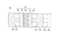
- FIG. 1 is a cross-sectional view for explaining a cell structure of a fuel cell according to an embodiment of the present invention
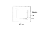
- FIG. 2 shows gaskets arranged on both surfaces of the outer peripheral portion of the membrane electrode assembly shown in FIG. It is a top view for doing.
- the unit cell 10 is applied to, for example, a polymer electrolyte fuel cell (PEFC) using hydrogen as a fuel, and includes a membrane electrode assembly 20 and separators 50 and 55.
- PEFC polymer electrolyte fuel cell
- the unit cell 10 further includes a cooling plate 58, and a groove 59 provided in the cooling plate 58 forms a refrigerant flow path through which a refrigerant for cooling the unit cell 10 flows.
- the membrane electrode assembly 20 includes a polymer electrolyte membrane 30, catalyst layers 32 and 33, gas diffusion layers (GDLs) 35 and 36, and gaskets 40 and 45.
- GDLs gas diffusion layers
- the catalyst layer 32 is an anode catalyst layer that includes a catalyst component, a conductive catalyst carrier that supports the catalyst component, and a polymer electrolyte, and in which a hydrogen oxidation reaction proceeds. It is arranged on the side.
- the catalyst layer 33 is a cathode catalyst layer that includes a catalyst component, a conductive catalyst carrier that supports the catalyst component, and a polymer electrolyte, and in which the oxygen reduction reaction proceeds. It is arranged on the side.
- the polymer electrolyte membrane 30 has a function of selectively permeating protons generated in the catalyst layer 32 to the catalyst layer 33 and does not mix the fuel gas supplied to the anode side and the oxidant gas supplied to the cathode side. It functions as a partition wall.
- the gas diffusion layer 35 is an anode gas diffusion layer for dispersing the fuel gas supplied to the anode side, and is located between the separator 50 and the catalyst layer 32.
- the gas diffusion layer 36 is a cathode gas diffusion layer for dispersing the oxidant gas supplied to the cathode side, and is located between the separator 55 and the catalyst layer 33.
- the gaskets 40 and 45 have a frame shape and are arranged on both surfaces of the outer peripheral portion of the polymer electrolyte membrane 30.
- the gasket 40 is positioned so as to surround the catalyst layer 32 and has a function of preventing the fuel gas supplied to the catalyst layer 32 from leaking to the outside.
- the gasket 45 is positioned so as to surround the catalyst layer 33 and has a function of preventing the oxidant gas supplied to the catalyst layer 33 from leaking to the outside.
- the separators 50 and 55 have a function of electrically connecting the single cells 10 in series and a function of a partition that blocks fuel gas, oxidant gas, and refrigerant from each other, and have substantially the same shape as the membrane electrode assembly 20.
- it is formed by pressing a stainless steel plate.
- the stainless steel plate is preferable in that it can be easily subjected to complicated machining and has good conductivity, and can be coated with a corrosion-resistant coating as necessary.
- the separator 50 is an anode separator disposed on the anode side of the membrane electrode assembly 20, and faces the catalyst layer 32, and forms a gas channel 52 that is located between the membrane electrode assembly 20 and the separator 50.
- Have The groove (gas flow path) 82 is used for supplying the fuel gas to the catalyst layer 32.
- the separator 55 is a cathode separator disposed on the cathode side of the membrane electrode assembly 20, and faces the catalyst layer 33 and forms a groove 57 that forms a gas flow path positioned between the membrane electrode assembly 20 and the separator 55.
- Have The groove (gas flow path) 87 is used to supply the oxidant gas to the catalyst layer 33.
- the polymer electrolyte membrane 30 is a porous polymer electrolyte membrane made of a perfluorocarbon sulfonic acid polymer, a porous resin membrane having a sulfonic acid group, and a porous material impregnated with an electrolyte component such as phosphoric acid or ionic liquid.
- a shaped film can be applied.
- the perfluorocarbon sulfonic acid polymer include Nafion (registered trademark, manufactured by DuPont), Aciplex (registered trademark, manufactured by Asahi Kasei Co., Ltd.), Flemion (registered trademark, manufactured by Asahi Glass Co., Ltd.), and the like.
- the porous film is made of polytetrafluoroethylene (PTFE) or polyvinylidene fluoride (PVDF).
- the thickness of the polymer electrolyte membrane 30 is not particularly limited, but is preferably 5 to 300 ⁇ m, more preferably 10 to 200 ⁇ m from the viewpoint of strength, durability, and output characteristics.
- the catalyst component used for the catalyst layer (cathode catalyst layer) 35 is not particularly limited as long as it has a catalytic action in the oxygen reduction reaction.
- the catalyst component used for the catalyst layer (anode catalyst layer) 34 is not particularly limited as long as it has a catalytic action for the oxidation reaction of hydrogen.
- catalyst components include, for example, platinum, ruthenium, iridium, rhodium, palladium, osmium, tungsten, lead, iron, chromium, cobalt, nickel, manganese, vanadium, molybdenum, gallium, aluminum and other metals, and alloys thereof. Etc. are selected. In order to improve catalytic activity, poisoning resistance to carbon monoxide, heat resistance, etc., the catalyst component preferably contains at least platinum.
- the catalyst components applied to the cathode catalyst layer and the anode catalyst layer need not be the same, and can be changed as appropriate.
- the conductive carrier of the catalyst used for the catalyst layers 32 and 33 is particularly limited as long as it has a specific surface area for supporting the catalyst component in a desired dispersed state and sufficient electronic conductivity as a current collector.
- the main component is preferably carbon particles.
- the carbon particles are composed of, for example, carbon black, activated carbon, coke, natural graphite, and artificial graphite.
- the polymer electrolyte used for the catalyst layers 32 and 33 is not particularly limited as long as it is a substance having at least high proton conductivity.
- a fluorine-based electrolyte containing a fluorine atom in all or part of the polymer skeleton or a polymer A hydrocarbon-based electrolyte that does not contain a fluorine atom in the skeleton is applicable.
- the polymer electrolyte used for the catalyst layers 32 and 33 may be the same as or different from the polymer electrolyte used for the polymer electrolyte membrane 30, but the catalyst layers 32 and 33 adhere to the polymer electrolyte membrane 30. From the viewpoint of improving the properties, it is preferable that they are the same.
- the gas diffusion layers 35 and 36 are configured by using, as a base material, a sheet-like material having conductivity and porosity such as a carbon woven fabric such as glassy carbon, a paper-like paper body, a felt, and a nonwoven fabric.
- the thickness of the substrate is not particularly limited, but is preferably 30 to 500 ⁇ m from the viewpoint of mechanical strength and permeability such as gas and water.
- the gas diffusion layers 35 and 36 preferably contain a water repellent in the base material from the viewpoint of water repellency and suppression of the flooding phenomenon.
- water repellent examples include fluorine-based polymer materials such as PTFE, PVDF, polyhexafluoropropylene, tetrafluoroethylene-hexafluoropropylene copolymer (FEP), polypropylene, and polyethylene.
- fluorine-based polymer materials such as PTFE, PVDF, polyhexafluoropropylene, tetrafluoroethylene-hexafluoropropylene copolymer (FEP), polypropylene, and polyethylene.
- the gaskets 40 and 45 are made of, for example, a rubber material, a fluorine-based polymer material, or a thermoplastic resin.
- the rubber material include fluorine rubber, silicon rubber, ethylene propylene rubber (EPDM), and polyisobutylene rubber.
- the fluorine-based polymer material include PTFE, PVDF, polyhexafluoropropylene, and FEP.
- the thermoplastic resin is polyolefin or polyester.
- the polyester is, for example, polyethylene naphthalate (PEN).
- the thickness of the gaskets 40 and 45 is not particularly limited, but is preferably 50 ⁇ m to 2 mm, and more preferably 100 ⁇ m to 1 mm.
- the separators 50 and 55 are not limited to the form made of stainless steel, and other metal materials (for example, aluminum and clad material) and carbon such as dense carbon graphite can also be applied.
- the groove parts 52 and 72 can be formed by cutting, for example.
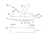
- FIG. 3 is a side view for explaining a fuel cell electrolyte membrane gripping device according to an embodiment of the present invention
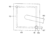
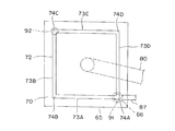
- FIGS. 4, 5 and 6 are for explaining a support shown in FIG.
- FIG. 7 is a cross-sectional view for explaining the groove portion shown in FIG. 5.
- a gripping device 60 shown in FIG. 3 is used to dispose the gaskets 40 and 45 on both surfaces of the polymer electrolyte membrane 20, and includes a support 65, a transport device 80, an air suction unit 85, and a clogging detection device 90. .
- the support 65 has a flat portion 70 that adsorbs the polymer electrolyte membrane 30 on which the catalyst layers 32 and 33 are arranged.
- the plane part 70 has a groove part 72 connected to the air suction part 85.
- the polymer electrolyte membrane 30 adsorbed on the flat portion 70 can be applied in a form in which a catalyst layer is disposed only on one surface.
- the groove portion 72 has a downward U-shaped cross section (see FIG. 7), has a frame shape having straight portions 73A to 73D and bent portions 74A to 74D, and the catalyst layer 32 disposed on the polymer electrolyte membrane 30. , 33 are aligned outside the outer peripheral edge. Therefore, the outer peripheral edge 31 of the polymer electrolyte membrane 30 is adsorbed by sucking the air in the groove 72.
- the transfer device 80 (see FIG. 3) is composed of, for example, a multi-axis robot hand, and the outer peripheral edge 31 of the polymer electrolyte membrane 30 on which the catalyst layers 32 and 33 are arranged is laminated on the gasket 40 (45).
- the gasket 40 (45) is used, for example, to convey the support body 65, and is disposed on the flat portion 96 of the fixed mounting table 95, for example.
- the polymer electrolyte membrane 30 can be easily positioned as compared with the configuration in which the mounting table 95 moves.
- the flat portion 96 is made of, for example, a porous member, and is connected to an external vacuum source (not shown) so as to suck the gasket 40 (45).
- the polymer electrolyte membrane 30 laminated on the gasket 40 is then inverted and laminated to obtain the polymer electrolyte membrane 30 in which the gaskets 40 and 45 are arranged on both sides of the outer peripheral portion.
- the groove 72 is frame-shaped and is positioned outside the outer peripheral edges of the catalyst layers 32 and 33, so that the catalyst layers 32 and 33 are not directly sucked, and are temporarily separated from the catalyst layer. Even if the catalyst particles are sucked, the polymer electrolyte membrane 30 is not adsorbed by the suction holes as compared with a mode using a porous substrate (adsorption holes) that may cause clogging in many suction holes. Occurrence is suppressed, and a reduction in production efficiency is prevented. Therefore, it is possible to provide a fuel cell electrolyte membrane gripping device capable of exhibiting good production efficiency.
- suction by the groove portion 72 is preferable in that production efficiency can be improved because release of the suction pressure proceeds instantaneously as compared to suction through a porous substrate having a large number of suction holes. Further, even if contamination occurs by sucking fine particles floating in the atmosphere or fine particles adhering to the polymer electrolyte membrane 30, occurrence of clogging is similarly suppressed.
- the conveying device 80 is not limited to a form using a multi-axis robot hand, and may be configured by combining a plurality of linear actuators, for example.
- the drive source is preferably a servo motor having good controllability and electrically synchronously controlled.
- the transport device 80 can be omitted.
- the mounting table 95 is transported by the transport device provided on the mounting table 95 toward the polymer electrolyte membrane 30 adsorbed to the support 65 arranged in a fixed manner.
- the mounting table 95 is positioned so that the outer peripheral edge 31 of the polymer electrolyte membrane 30 is laminated on the gasket 40 (45) disposed in 96.
- the air suction part 85 has a manifold 86 and a piping system 87 as shown in FIGS.
- the manifold 86 is constituted by, for example, a suction valve, is positioned at the bent portion 74 ⁇ / b> A of the groove portion 72, and communicates with the groove portion 72.
- the manifold 86 can be easily connected.
- the manifold 86 air suction part 85
- the groove 72 is frame-shaped, the manifold 86 (air suction part 85) is disposed in the bent part 74A of the groove 72, so that the resistance during air suction is reduced and the gasket 40 (45) is adsorbed.
- the pressure fluctuation at the time the generation of wrinkles in the polymer electrolyte membrane 30 is further suppressed.
- the clogging detection device 90 has differential pressure gauges 91 and 92 as clearly shown in FIG.
- the differential pressure gauges 91 and 92 are, for example, of an elastic element type, and are used to detect pressure when air is sucked by the air suction part 85 (manifold 86 and piping system 87).
- the differential pressure gauge 91 is disposed on the manifold 86, and the differential pressure gauge 92 is disposed on the bent portion 74 ⁇ / b> C located on the diagonal line of the differential pressure gauge 91.
- the groove part 72 Since the groove part 72 is frame-shaped, the places where clogging is likely to occur are the bent parts 74B and 74D. However, when one of the bent portions 74B and 74D is clogged, the other flow path of the bent portions 74B and 74D functions as a detour, so that adsorption failure (gripping failure) of the polymer electrolyte membrane 30 is suppressed. In addition, when clogging occurs in both of the bent portions 74B and 74D, the differential pressure gauges 91 and 92 can be detected early and quickly.
- a pressure detection device corresponding to the number of suction holes is required to detect clogging in units of suction holes. If the size of the molecular electrolyte membrane 30 is taken into consideration, the installation is impossible, and even if it is installed, the apparatus becomes complicated and the maintenance management becomes complicated. Further, when clogging of a large number of suction holes is detected at once by the pressure detection device provided in the upstream portion of the manifold, there is a possibility that partial clogging cannot be detected appropriately.
- the air suction line according to the present embodiment is configured by the groove portion 72, and partial blockage is unlikely to occur, and an abnormality of the groove portion 72 is caused by the minimum necessary number, that is, two pressure detection devices. This is preferable in that it does not miss a malfunction due to clogging of the groove 72.
- the suction force (gripping force) of the support 65, which is a gripping jig, with respect to the polymer electrolyte membrane 30 is preferably smaller than the deformation stress of the polymer electrolyte membrane 30, and a plurality of grooves may be provided.
- the stress due to suction in one groove is preferably smaller than the deformation stress in the groove inward direction of the polymer electrolyte membrane 30.
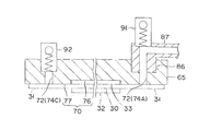
- FIG. 8 is a cross-sectional view for explaining Modification Example 1 according to the embodiment of the present invention.
- the support 65 is preferably formed of a material that transmits light, as shown in FIG.
- the material that transmits light is, for example, an acrylic resin.
- the state of the groove 72, the polymer electrolyte membrane 30, and the catalyst layers 32 and 33 can be optically detected. Therefore, for example, by visually observing the state (adsorption state) of the outer peripheral edge 31 of the polymer electrolyte membrane 30, the clogged portion can be easily identified. Further, for example, when the outer peripheral edge 31 of the polymer electrolyte membrane 30 is placed on the frame-shaped gasket 40 (45), the polymer electrolyte membrane 30, the catalyst layers 32 and 33, and the gasket 40 (45) are visually observed. Since the position can be confirmed, it is not necessary to perform positioning by relying on the operator's can and reliability is improved. Furthermore, for example, since the position can be confirmed using an infrared sensor, it is easy to automate equipment (use as an element of production equipment) by work of a robot or the like.
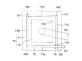
- FIG. 9 and FIG. 10 are a bottom view and a cross-sectional view for explaining a second modification according to the embodiment of the present invention.
- a recess 76 is disposed on the flat portion 70 of the support 65. It is preferable to do.
- the concave portion 76 has a substantially rectangular shape corresponding to the planar shape of the catalyst layers 32 and 33, and the depth thereof substantially matches the thickness of the catalyst layers 32 and 33, and is not intended for the polymer electrolyte membrane 30. It is set so that no distortion occurs.
- a frame-shaped portion 77 is disposed around the recess 76.
- the frame portion 77 is provided with a groove portion 72 and constitutes an adsorption surface of the outer peripheral edge 31 of the polymer electrolyte membrane 30.
- the concave portion 76 may be provided with a through-hole 76A in order to allow the atmosphere to escape when the polymer electrolyte membrane 30 of the support body 65, which is a holding jig, is brought close to the gasket.
- the manifold 86 is preferably provided so as not to interfere with the recess 76.
- FIG. 11 is a bottom view for explaining the third modification according to the embodiment of the present invention.
- the bent portions 74A to 74D of the groove portion 72 are not limited to a substantially right-angled shape, and may be a curved surface shape that is gently bent. In this case, the air flow in the bent portions 74A to 74D becomes smooth, and the resistance during air suction is reduced.
- FIG. 12 is a side view for explaining the modified example 4 according to the embodiment of the present invention.
- the electrolyte membrane 30 is not limited to a form of being supported downward, and the electrolyte membrane 30 is disposed (placed) on the flat portion 70 of the fixed support 65A as in the gripping device 60A shown in FIG. ) Is also possible.
- the gasket 40 (45) is adsorbed by the flat portion 96A of the support body 95A disposed above, so that the gasket 40 (45) is supported downward and conveyed by the conveyance device 80A connected to the support body 95A. It is positioned so as to be laminated on the outer peripheral edge 31 of the electrolyte membrane 30.
- the electrolyte membrane is adsorbed by the groove portion disposed in the flat portion of the support, and thus wrinkles are prevented from occurring in the polymer electrolyte membrane. Furthermore, since the groove is frame-shaped and aligned outside the outer peripheral edge of the catalyst layer, the catalyst layer is not directly sucked, the occurrence of clogging is suppressed, and the reduction in production efficiency is suppressed. I can do it. Therefore, it is possible to provide a fuel cell electrolyte membrane gripping device capable of exhibiting good production efficiency.
- the groove is frame-shaped, the manifold (air suction part) is located at the bent part of the groove, so the resistance during air suction is reduced and the pressure fluctuation when adsorbing the polymer electrolyte membrane is reduced. Thus, the generation of wrinkles in the polymer electrolyte membrane is further suppressed.
- the support When the support is formed from a material that transmits light, the state of the groove, the polymer electrolyte membrane, and the catalyst layer can be detected optically. Therefore, for example, the clogged portion can be easily identified by visually observing the state of the outer periphery of the polymer electrolyte membrane (adsorption state). Further, for example, when the outer periphery of the polymer electrolyte membrane is placed on a frame-shaped gasket, the positions of the polymer electrolyte membrane, the catalyst layer, and the gasket can be confirmed by visual observation. Reliable positioning is unnecessary and reliability is improved. Furthermore, for example, since the position can be confirmed using an infrared sensor, it is easy to automate equipment (use as an element of production equipment) by work of a robot or the like.
- the manifold air suction part
- the fuel cell can be constituted by a polymer electrolyte fuel cell using methanol as a fuel, or can be applied as a stationary power source.
- the polymer electrolyte fuel cell using methanol as a fuel is a direct methanol fuel cell (DMFC) or a micro fuel cell (passive DMFC)).
- DMFC direct methanol fuel cell
- passive DMFC micro fuel cell
- fuels other than hydrogen and methanol ethanol, 1-propanol, 2-propanol, primary butanol, secondary butanol, tertiary butanol, dimethyl ether, diethyl ether, ethylene glycol, diethylene glycol, etc. can be applied. It is.
- the number of manifolds for communicating with the grooves and sucking air is not limited to one, and a plurality of manifolds may be arranged. Moreover, it is also possible to make a groove part into a double structure. Further, the first to third modifications can be combined with the fourth modification.
Landscapes
- Engineering & Computer Science (AREA)
- Life Sciences & Earth Sciences (AREA)
- Manufacturing & Machinery (AREA)
- Sustainable Development (AREA)
- Sustainable Energy (AREA)
- Chemical & Material Sciences (AREA)
- Chemical Kinetics & Catalysis (AREA)
- Electrochemistry (AREA)
- General Chemical & Material Sciences (AREA)
- Mechanical Engineering (AREA)
- Robotics (AREA)
- Fuel Cell (AREA)
Abstract
Description
20 膜電極接合体、
30 高分子電解質膜、
31 外周縁、
32,33 触媒層、
35,36 ガス拡散層、
40,45 ガスケット、
50,55 セパレータ、
52,57 溝部、
58 冷却板、
59 溝部、
60,60A 把持装置、
65,65A 支持体、
70 平面部、
72 溝部、
73A~73D 直線状部、
74A~74D 曲折部、
76 凹部、
76A 貫通孔、
77 枠状部、
80,80A 搬送装置、
85 空気吸引部、
86 マニホールド、
87 配管系、
90 目詰まり検出装置、
91,92 差圧計、
95 載置台、
95A 支持体、
96,96A 平面部。
Claims (6)
- 膜電極接合体を構成する、触媒層が配置された電解質膜を支持する平面部を有する支持体を有し、
前記平面部は、前記触媒層の外周縁の外側に位置合わせされた枠状の溝部を有し、
前記溝部は、空気吸引部と接続されており、前記溝部の空気が吸引されることで前記電解質膜を吸着する、燃料電池用電解質膜の把持装置。 - 前記溝は、前記空気吸引部が接続される曲折部を有する請求項1に記載の燃料電池用電解質膜の把持装置。
- 前記支持体は、光を透過する材質から形成される請求項1又は請求項2に記載の燃料電池用電解質膜の把持装置。
- 前記空気吸引部によって空気を吸引する際の圧力を検出する検出装置を、さらに有する請求項1~3のいずれか1項に記載の燃料電池用電解質膜の把持装置。
- 前記溝部の断面形状は、コ字状である請求項1~4のいずれか1項に記載の燃料電池用電解質膜の把持装置。
- 前記電解質膜の外周縁を、枠状のガスケットに積層するように、前記支持体を搬送する搬送装置を、さらに有する請求項1~5いずれか1項に記載の燃料電池用ガスケットの把持装置。
Priority Applications (5)
| Application Number | Priority Date | Filing Date | Title |
|---|---|---|---|
| US14/413,144 US9539730B2 (en) | 2012-07-10 | 2013-06-24 | Holding apparatus for fuel cell electrolyte membrane |
| CN201380036246.8A CN104428933B (zh) | 2012-07-10 | 2013-06-24 | 燃料电池用电解质膜的把持装置 |
| CA2878828A CA2878828C (en) | 2012-07-10 | 2013-06-24 | Holding apparatus for fuel cell electrolyte membrane |
| EP13815946.2A EP2874217B1 (en) | 2012-07-10 | 2013-06-24 | Holding device for fuel cell electrolyte membrane |
| JP2014524715A JP5880711B2 (ja) | 2012-07-10 | 2013-06-24 | 燃料電池用電解質膜の把持装置 |
Applications Claiming Priority (2)
| Application Number | Priority Date | Filing Date | Title |
|---|---|---|---|
| JP2012-154958 | 2012-07-10 | ||
| JP2012154958 | 2012-07-10 |
Publications (1)
| Publication Number | Publication Date |
|---|---|
| WO2014010398A1 true WO2014010398A1 (ja) | 2014-01-16 |
Family
ID=49915864
Family Applications (1)
| Application Number | Title | Priority Date | Filing Date |
|---|---|---|---|
| PCT/JP2013/067275 WO2014010398A1 (ja) | 2012-07-10 | 2013-06-24 | 燃料電池用電解質膜の把持装置 |
Country Status (6)
| Country | Link |
|---|---|
| US (1) | US9539730B2 (ja) |
| EP (1) | EP2874217B1 (ja) |
| JP (1) | JP5880711B2 (ja) |
| CN (1) | CN104428933B (ja) |
| CA (1) | CA2878828C (ja) |
| WO (1) | WO2014010398A1 (ja) |
Cited By (1)
| Publication number | Priority date | Publication date | Assignee | Title |
|---|---|---|---|---|
| JP2017107753A (ja) * | 2015-12-10 | 2017-06-15 | 本田技研工業株式会社 | 樹脂枠付き電解質膜・電極構造体の製造方法及びその製造装置 |
Families Citing this family (5)
| Publication number | Priority date | Publication date | Assignee | Title |
|---|---|---|---|---|
| CN104428931B (zh) | 2012-07-10 | 2016-04-20 | 日产自动车株式会社 | 燃料电池用衬垫的把持装置 |
| JP6655941B2 (ja) * | 2015-10-19 | 2020-03-04 | 東京応化工業株式会社 | 触媒層形成装置、触媒層の形成方法、燃料電池製造システム、及び燃料電池の製造方法 |
| CN109789561B (zh) * | 2016-11-09 | 2022-05-24 | 株式会社东芝 | 把持工具以及把持系统 |
| CN113830591B (zh) * | 2020-06-24 | 2024-05-10 | 志圣科技(广州)有限公司 | 取膜装置及取膜方法 |
| KR20230012922A (ko) * | 2021-07-16 | 2023-01-26 | 주식회사 엘지에너지솔루션 | 지지 플레이트 및 이를 포함하는 픽앤플레이스 장치 |
Citations (3)
| Publication number | Priority date | Publication date | Assignee | Title |
|---|---|---|---|---|
| JP2002370245A (ja) * | 2001-06-15 | 2002-12-24 | Honda Motor Co Ltd | 燃料電池用セパレータ取出装置 |
| JP2004235089A (ja) * | 2003-01-31 | 2004-08-19 | Toyota Motor Corp | 薄膜積層装置および積層方法 |
| JP2010238655A (ja) | 2009-03-11 | 2010-10-21 | Takatori Corp | 燃料電池セルの製造装置 |
Family Cites Families (14)
| Publication number | Priority date | Publication date | Assignee | Title |
|---|---|---|---|---|
| GB1165382A (en) * | 1966-08-08 | 1969-09-24 | Pilkington Brothers Ltd | Improvements in or relating to Vacuum Holding Apparatus |
| US4559718A (en) * | 1983-08-02 | 1985-12-24 | Oki Electric Industry Co., Ltd. | Method and apparatus for drying semiconductor wafers |
| EP0360985B1 (en) * | 1988-06-29 | 1995-01-25 | Matsushita Electric Industrial Co., Ltd. | Electronic parts engaging apparatus |
| JPH02111100A (ja) * | 1988-10-20 | 1990-04-24 | Matsushita Electric Ind Co Ltd | 部品装着装置 |
| JPH0797599B2 (ja) * | 1990-04-27 | 1995-10-18 | 株式会社芝浦製作所 | 基板検出装置 |
| US6032997A (en) * | 1998-04-16 | 2000-03-07 | Excimer Laser Systems | Vacuum chuck |
| US6341808B1 (en) * | 2000-06-29 | 2002-01-29 | International Business Machines Corporation | Flexible sheet handling apparatus |
| EP1311827A2 (en) * | 2000-08-22 | 2003-05-21 | Ade Corporation | Ring chuck to hold 200 and 300 mm wafer |
| DE10140248B4 (de) * | 2001-08-09 | 2006-09-28 | J. Schmalz Gmbh | Unterdruckhandhabungseinrichtung |
| US6749713B2 (en) | 2002-04-03 | 2004-06-15 | 3M Innovative Properties Company | Apparatus and method for separating a fuel cell assembly from a bonding fixture |
| US6756146B2 (en) | 2002-04-03 | 2004-06-29 | 3M Innovative Properties Company | Apparatus and method for automatically stacking fuel cell material layers |
| JP2005536861A (ja) * | 2002-08-30 | 2005-12-02 | ペメアス ゲーエムベーハー | 薄膜材料を有するデバイスの製造を容易にするための取付け具および方法 |
| US20040042789A1 (en) | 2002-08-30 | 2004-03-04 | Celanese Ventures Gmbh | Method and apparatus for transferring thin films from a source position to a target position |
| DE102010025885A1 (de) * | 2010-07-02 | 2012-01-05 | Manz Tübingen Gmbh | Verfahren zum Stapeln von Blättern, insbesondere zur Fertigung einer Lithium-Ionen-Batterie |
-
2013
- 2013-06-24 WO PCT/JP2013/067275 patent/WO2014010398A1/ja active Application Filing
- 2013-06-24 CN CN201380036246.8A patent/CN104428933B/zh not_active Expired - Fee Related
- 2013-06-24 EP EP13815946.2A patent/EP2874217B1/en not_active Not-in-force
- 2013-06-24 CA CA2878828A patent/CA2878828C/en not_active Expired - Fee Related
- 2013-06-24 JP JP2014524715A patent/JP5880711B2/ja not_active Expired - Fee Related
- 2013-06-24 US US14/413,144 patent/US9539730B2/en not_active Expired - Fee Related
Patent Citations (3)
| Publication number | Priority date | Publication date | Assignee | Title |
|---|---|---|---|---|
| JP2002370245A (ja) * | 2001-06-15 | 2002-12-24 | Honda Motor Co Ltd | 燃料電池用セパレータ取出装置 |
| JP2004235089A (ja) * | 2003-01-31 | 2004-08-19 | Toyota Motor Corp | 薄膜積層装置および積層方法 |
| JP2010238655A (ja) | 2009-03-11 | 2010-10-21 | Takatori Corp | 燃料電池セルの製造装置 |
Non-Patent Citations (1)
| Title |
|---|
| See also references of EP2874217A4 * |
Cited By (1)
| Publication number | Priority date | Publication date | Assignee | Title |
|---|---|---|---|---|
| JP2017107753A (ja) * | 2015-12-10 | 2017-06-15 | 本田技研工業株式会社 | 樹脂枠付き電解質膜・電極構造体の製造方法及びその製造装置 |
Also Published As
| Publication number | Publication date |
|---|---|
| EP2874217A1 (en) | 2015-05-20 |
| CN104428933A (zh) | 2015-03-18 |
| CN104428933B (zh) | 2018-04-10 |
| CA2878828A1 (en) | 2014-01-16 |
| CA2878828C (en) | 2016-10-04 |
| EP2874217B1 (en) | 2017-04-19 |
| US9539730B2 (en) | 2017-01-10 |
| EP2874217A4 (en) | 2015-08-19 |
| US20150165627A1 (en) | 2015-06-18 |
| JP5880711B2 (ja) | 2016-03-09 |
| JPWO2014010398A1 (ja) | 2016-06-20 |
Similar Documents
| Publication | Publication Date | Title |
|---|---|---|
| JP5880711B2 (ja) | 燃料電池用電解質膜の把持装置 | |
| JP5920479B2 (ja) | 塗布装置 | |
| KR20070057151A (ko) | 멤브레인 전극 조립체 | |
| US9496562B2 (en) | Electrode assembly for solid polymer fuel cell | |
| JP5874830B2 (ja) | 燃料電池用ガスケット、燃料電池用接合体、およびシート部材の接合方法 | |
| JP2017152084A (ja) | 膜・電極接合体の製造装置 | |
| JP5880710B2 (ja) | 燃料電池用ガスケットの把持装置 | |
| JP5854139B2 (ja) | 膜電極接合体 | |
| WO2015177850A1 (ja) | メタルマスク及びスクリーン印刷装置 | |
| JP2006338937A (ja) | 電解質膜−電極接合体の製造方法 | |
| JP2011065828A (ja) | 燃料電池用の膜電極接合体の製造方法 |
Legal Events
| Date | Code | Title | Description |
|---|---|---|---|
| 121 | Ep: the epo has been informed by wipo that ep was designated in this application |
Ref document number: 13815946 Country of ref document: EP Kind code of ref document: A1 |
|
| ENP | Entry into the national phase |
Ref document number: 2014524715 Country of ref document: JP Kind code of ref document: A |
|
| WWE | Wipo information: entry into national phase |
Ref document number: 14413144 Country of ref document: US |
|
| ENP | Entry into the national phase |
Ref document number: 2878828 Country of ref document: CA |
|
| NENP | Non-entry into the national phase |
Ref country code: DE |
|
| REEP | Request for entry into the european phase |
Ref document number: 2013815946 Country of ref document: EP |
|
| WWE | Wipo information: entry into national phase |
Ref document number: 2013815946 Country of ref document: EP |