WO2014010393A1 - 色素増感太陽電池 - Google Patents
色素増感太陽電池 Download PDFInfo
- Publication number
- WO2014010393A1 WO2014010393A1 PCT/JP2013/067182 JP2013067182W WO2014010393A1 WO 2014010393 A1 WO2014010393 A1 WO 2014010393A1 JP 2013067182 W JP2013067182 W JP 2013067182W WO 2014010393 A1 WO2014010393 A1 WO 2014010393A1
- Authority
- WO
- WIPO (PCT)
- Prior art keywords
- electrolyte
- dye
- solar cell
- sensitized solar
- sealing portion
- Prior art date
- Legal status (The legal status is an assumption and is not a legal conclusion. Google has not performed a legal analysis and makes no representation as to the accuracy of the status listed.)
- Ceased
Links
Images


Classifications
-
- H—ELECTRICITY
- H01—ELECTRIC ELEMENTS
- H01G—CAPACITORS; CAPACITORS, RECTIFIERS, DETECTORS, SWITCHING DEVICES, LIGHT-SENSITIVE OR TEMPERATURE-SENSITIVE DEVICES OF THE ELECTROLYTIC TYPE
- H01G9/00—Electrolytic capacitors, rectifiers, detectors, switching devices, light-sensitive or temperature-sensitive devices; Processes of their manufacture
- H01G9/20—Light-sensitive devices
- H01G9/2004—Light-sensitive devices characterised by the electrolyte, e.g. comprising an organic electrolyte
-
- H—ELECTRICITY
- H01—ELECTRIC ELEMENTS
- H01G—CAPACITORS; CAPACITORS, RECTIFIERS, DETECTORS, SWITCHING DEVICES, LIGHT-SENSITIVE OR TEMPERATURE-SENSITIVE DEVICES OF THE ELECTROLYTIC TYPE
- H01G9/00—Electrolytic capacitors, rectifiers, detectors, switching devices, light-sensitive or temperature-sensitive devices; Processes of their manufacture
- H01G9/20—Light-sensitive devices
- H01G9/2027—Light-sensitive devices comprising an oxide semiconductor electrode
- H01G9/2031—Light-sensitive devices comprising an oxide semiconductor electrode comprising titanium oxide, e.g. TiO2
-
- H—ELECTRICITY
- H01—ELECTRIC ELEMENTS
- H01G—CAPACITORS; CAPACITORS, RECTIFIERS, DETECTORS, SWITCHING DEVICES, LIGHT-SENSITIVE OR TEMPERATURE-SENSITIVE DEVICES OF THE ELECTROLYTIC TYPE
- H01G9/00—Electrolytic capacitors, rectifiers, detectors, switching devices, light-sensitive or temperature-sensitive devices; Processes of their manufacture
- H01G9/20—Light-sensitive devices
- H01G9/2059—Light-sensitive devices comprising an organic dye as the active light absorbing material, e.g. adsorbed on an electrode or dissolved in solution
-
- Y—GENERAL TAGGING OF NEW TECHNOLOGICAL DEVELOPMENTS; GENERAL TAGGING OF CROSS-SECTIONAL TECHNOLOGIES SPANNING OVER SEVERAL SECTIONS OF THE IPC; TECHNICAL SUBJECTS COVERED BY FORMER USPC CROSS-REFERENCE ART COLLECTIONS [XRACs] AND DIGESTS
- Y02—TECHNOLOGIES OR APPLICATIONS FOR MITIGATION OR ADAPTATION AGAINST CLIMATE CHANGE
- Y02E—REDUCTION OF GREENHOUSE GAS [GHG] EMISSIONS, RELATED TO ENERGY GENERATION, TRANSMISSION OR DISTRIBUTION
- Y02E10/00—Energy generation through renewable energy sources
- Y02E10/50—Photovoltaic [PV] energy
- Y02E10/542—Dye sensitized solar cells
Definitions
- the present invention relates to a dye-sensitized solar cell.
- a dye-sensitized solar cell includes, as its elements, a transparent electrode in which a transparent conductive film is formed on a transparent substrate such as a glass plate, a counter electrode, an electrolyte disposed between these two electrodes, It is comprised from the photocatalyst film
- a photocatalyst film a film in which a metal oxide such as titanium oxide (TiO 2 ) is formed and then a photosensitizing dye such as ruthenium is adsorbed is known.
- each element is provided with a sealing portion in order to prevent the electrolyte from flowing out.
- a high-viscosity electrolyte may be used without providing a sealing portion.
- the dye-sensitized solar cell module described in Patent Document 1 can reliably prevent the electric layer 7 from flowing out by the double seal structure of the element seal portion 8 and the external seal portion 9,
- Various problems occur when the electrolyte (electrolyte layer 7) and the sealing portion (element seal portion 8) are in contact for a long period of time.
- the first problem is that the sealing portion is eroded and deteriorated by the electrolyte
- the second problem is that the sealing portion dissolves into the electrolyte and the battery performance is lowered.
- a high-viscosity electrolyte is used, not only the battery performance is degraded, but the aging is prolonged.
- the present invention is capable of preventing deterioration of the sealing portion, preventing deterioration in battery performance and product life due to dissolution of the sealing portion into the electrolyte, and preventing increase in aging time.
- An object is to provide a solar cell.
- the dye-sensitized solar cell of the present invention includes a transparent electrode, a counter electrode having a substrate, an electrolyte disposed between these electrodes, and an electrolyte between both electrodes.
- a dye-sensitized solar cell comprising a sealing portion disposed around, and a photocatalytic film disposed between both electrodes and on the transparent electrode side,
- the electrolyte is composed of a first electrolyte having fluidity and a second electrolyte that is higher in viscosity than the first electrolyte and disposed around the first electrolyte between the two electrodes to prevent the flow of the first electrolyte.
- a gap is formed between the electrolyte and the sealing portion, and the electrolyte and the sealing portion are not in contact with each other.
- the second electrolyte of the dye-sensitized solar cell according to the first aspect is obtained by adding a thickener to the first electrolyte.
- the dye-sensitized solar cell of the present invention according to the third aspect is the dye-sensitized solar cell according to the first aspect or the second aspect, wherein the viscosity of the first electrolyte is 0.5 to 3.0 mPa ⁇ s. It is what is.
- the dye-sensitized solar cell according to the fourth aspect of the present invention is the dye-sensitized solar cell according to any one of the first to third aspects, wherein the viscosity of the second electrolyte is 10 to 50 Pa ⁇ s. It is.
- the sealing portion can be prevented from deteriorating, the battery performance and product life can be prevented from being lowered due to the sealing portion being dissolved into the electrolyte, and the aging can be prevented from being prolonged. it can.
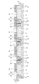
- FIG. 1 is a cross-sectional view showing a schematic configuration of the dye-sensitized solar cell
- FIG. 2 is a perspective view showing a schematic configuration (a counter electrode is omitted) of the dye-sensitized solar cell.
- the dye-sensitized solar cell includes a transparent electrode 1 as a negative electrode, a counter electrode 2 as a positive electrode, an electrolyte 3 disposed between these electrodes 1 and 2, and both A photocatalyst film (also referred to as a photocatalyst layer or a power generation layer) 4 disposed between the electrodes 1 and 2 on the transparent electrode 1 side, and a space 6 between the electrodes 1 and 2 around the electrolyte 3
- the sealing part 5 is comprised.
- the electrolyte 3 includes a second electrolyte 35 located on the outer peripheral side (periphery) and facing the gap 6, and a first electrolyte 33 located on the inner side of the second electrolyte 35.
- the first electrolyte 33 has a low viscosity of 0.5 to 3.0 [mPa ⁇ s] and has fluidity.
- the second electrolyte 35 has a viscosity of 10 to 50 [Pa ⁇ s], which is higher than the viscosity of the first electrolyte 33, and has a function as a bank that prevents the flow of the first electrolyte 33. For this reason, the electrolyte 3 maintains its shape without flowing and is not in contact with the sealing portion 5.
- the second electrolyte 35 has a minimum amount necessary for preventing the flow of the first electrolyte 33. That is, it is preferable that the amount of the second electrolyte 35 be minimized so long as the second electrolyte 35 is not broken by the hydraulic pressure of the first electrolyte 33.
- the ratio of the first electrolyte 33 and the second electrolyte 35 in the electrolyte 3 is set so as not to be affected by the deterioration of the battery performance and the aging time due to the second electrolyte 35. 2 Determined by the viscosity of the electrolyte 35, the amount of the electrolyte 3, and other design safety factors.
- the first electrolyte 33 is a main material
- the second electrolyte 35 is a sub-material.
- the gap 6 is a space formed between the electrolyte 3 (more precisely, the second electrolyte 35) and the sealing portion 5, and is the minimum necessary to maintain the non-contact between the electrolyte 3 and the sealing portion 5. Preferably there is. This is because the space inside the sealing portion 5 is finite, and if the gap 6 is large, the electrolyte 3 must be made small, and the battery performance deteriorates.
- the transparent electrode 1 includes a transparent substrate 11 and a transparent conductive film 12 formed (arranged) on the surface of the transparent substrate 11.
- the counter electrode 2 includes a transparent substrate 21 and a transparent conductive film 22 formed (arranged) on the surface of the transparent substrate 21.
- the transparent conductive film 22 is formed by forming a catalytic material (catalyst film 24).
- the transparent substrates 11 and 21 are not particularly limited, but although a synthetic resin plate, a glass plate, or the like is used as appropriate, it is light in weight, low in price, and safe (not easily damaged).
- a film made of a thermoplastic resin is preferred.
- the thermoplastic resin include polyester resins such as polyethylene naphthalate (PEN) and polyethylene terephthalate (PET), polycarbonate resins, and resins such as polyolefins.
- the transparent conductive films 12 and 22 are not particularly limited, but include tin-added indium oxide (ITO), tin oxide (SnO 2 ), indium zinc oxide (IZO), zinc oxide (ZnO), and the like.
- ITO indium oxide
- SnO 2 tin oxide
- IZO indium zinc oxide
- ZnO zinc oxide
- a thin film containing a conductive metal oxide is used, a thin film containing fluorine-added tin oxide (FTO) is preferable. This is because fluorine-added tin oxide (FTO) has high strength as a material, so that the applied voltage at the time of aging can be increased.
- FTO fluorine-added tin oxide
- the photocatalyst film 4 of the dye-sensitized solar cell to be manufactured This is because the adsorption of the sensitizing dye and the oxide semiconductor layer (both described later) can be strengthened.
- the counter electrode 2 is not limited to the transparent substrate 21 and the transparent conductive film 22 formed with a catalytic material, and may have any catalytic property.
- a material such as platinum or carbon having catalytic properties may be formed on a metal sheet such as aluminum, copper or tin or a mesh electrode. Examples of the method for forming the material having catalytic properties include sputtering and immersing the counter electrode 2 in a platinum nanocolloid solution.
- the counter electrode 2 has a conductive adhesive layer formed on the surface of the transparent substrate 21 on the electrolyte 3 side, and a separately generated vertically aligned carbon nanotube group was transferred to the conductive adhesive layer. It may be a thing.
- liquid electrolytes include iodine-based electrolytes, in which electrolyte components such as iodine, iodide ions, and tertiary butyl pyridine are dissolved in organic solvents such as ethylene carbonate and methoxyacetonitrile. It is.
- Examples of the gel electrolyte include dimethylpropylimidazolium iodide (DMPImI), metal iodide (lithium iodide, sodium iodide, potassium iodide, cesium iodide, calcium iodide), tetraalkylammonium iodide.
- DMPImI dimethylpropylimidazolium iodide
- metal iodide lithium iodide, sodium iodide, potassium iodide, cesium iodide, calcium iodide
- tetraalkylammonium iodide tetraalkylammonium iodide.
- Combinations of iodide and iodine such as iodine salts of quaternary ammonium compounds such as id, metal bromides (lithium bromide, sodium bromide, potassium bromide, cesium bromid
- the second electrolyte 35 of the electrolyte 3 a material obtained by adding a thickener to the first electrolyte 33 is used. That is, it can be said that the second electrolyte 35 is made of the same material as the first electrolyte 33. For this reason, in the electrolyte 3, since the unexpected chemical reaction by the contact with the 1st electrolyte 33 and the 2nd electrolyte 35 does not occur, a malfunction does not arise.
- the thickener include polyvinyl pyrrolidone (PVP).
- the amount of polyvinyl pyrrolidone (PVP) added is preferably the minimum amount necessary for the second electrolyte 35 to prevent the flow of the first electrolyte 33.
- the weight ratio of the second electrolyte 35 is about 10%. (10 [wt%]).
- the second electrolyte 35 may be made of a material that prevents the flow of the first electrolyte 33 without deteriorating the first electrolyte 33 other than the first electrolyte 33 added with a thickener. Good. Examples of this material include a cobalt complex electrolyte.
- the photocatalyst film 4 is formed of an oxide semiconductor layer to which a photosensitizing dye is adsorbed, and in the production thereof, a paste containing the oxide semiconductor is applied to the surface of the transparent electrode 1 and dried. Then, it is obtained by making a photosensitizing dye adsorb
- this adsorption method include immersing the transparent electrode 1 with the paste dried for a predetermined time in a dye solution obtained by dissolving a photosensitizing dye in an organic solvent.
- oxide semiconductor examples include metal oxides such as titanium oxide (TiO 2 ), tin oxide (SnO 2 ), tungsten oxide (WO 3 ), zinc oxide (ZnO), and niobium oxide (Nb 2 O 5 ).
- Fine particles photocatalyst fine particles are used. The particle diameter of these fine particles is not particularly limited, but is preferably about 5 to 100 ⁇ m.
- photosensitizing dyes include ruthenium complexes and iron complexes having ligands containing a bipyridine structure or a terpyridine structure, porphyrin-based or phthalocyanine-based metal complexes, or organic dyes such as eosin, rhodamine, merocyanine, and coumarin. used.
- ruthenium complexes and iron complexes having ligands containing a bipyridine structure or a terpyridine structure porphyrin-based or phthalocyanine-based metal complexes, or organic dyes such as eosin, rhodamine, merocyanine, and coumarin.
- organic dyes such as eosin, rhodamine, merocyanine, and coumarin.
- an organic dye from the viewpoint of solubility in an organic solvent.
- an organic solvent for dissolving the photosensitizing dye alcohol such as ethanol, acetonitrile,
- titanium oxide (TiO 2 ) was used as the oxide semiconductor, it was obtained by dissolving titanium (IV) isopropoxide (TTIP) in propanol for the purpose of strengthening the bond of titanium oxide.
- a solution (which is a photocatalyst precursor solution) may be mixed with the dye solution.
- the sealing part 5 is not particularly limited, but an acrylic resin sealant, a fluorine resin sealant, a silicone resin sealant, an epoxy resin sealant, and an olefin resin. Sealants, silane-modified resin-containing sealants, hot-melt sealants, photocurable resin sealants, and the like are used.
- metal oxide fine particles which are oxide semiconductors
- an organic solvent and water and stirred to produce an oxide solution.
- alcohol, acetone, hexane, etc. are used for this organic solvent.
- this oxide solution is applied or printed on the transparent conductive film 12.
- an oxide semiconductor layer is obtained by sintering the oxide solution apply
- the photocatalytic film 4 which is a negative electrode is obtained by adsorbing the photosensitizing dye to the oxide semiconductor layer by the method of immersing the transparent electrode 1 in the dye solution described above.
- the content of the photosensitizing dye in the dye solution is not particularly limited, but is preferably 0.2 ⁇ 10 ⁇ 3 to 1.0 ⁇ 10 ⁇ 3 [mol / L], More preferably, it is 0.3 ⁇ 10 ⁇ 3 to 0.6 ⁇ 10 ⁇ 3 [mol / L].
- the transparent electrode 1 (negative electrode) and the counter electrode 2 (positive electrode) are arranged to face each other, and the electrolyte 3 is arranged between both the electrodes 1 and 2.
- the specific method for arranging the electrolyte 3 differs depending on whether the first electrolyte 33 is a liquid electrolyte solution or a gel electrolyte solution.
- the first electrolyte 33 is a liquid electrolyte solution
- holes are formed in the transparent electrode 1 and / or the counter electrode 2 in advance, and the transparent electrode 1 and the counter electrode 2 are arranged to face each other.
- the second electrolyte 35 is disposed, and the sealing portion 5 is disposed (that is, sealed) through the gap 6 so as to face the outer peripheral side of the second electrolyte 35.
- the electrolyte 3 is formed by injecting the first electrolyte 33 from the hole and filling the first electrolyte 33 inside the second electrolyte 35.
- the second electrolyte 35 is disposed on the transparent electrode 1 or the counter electrode 2, and the sealing portion 5 is disposed via the gap 6 so as to face the outer peripheral side of the second electrolyte 35.
- the electrolyte 3 is formed by dropping and filling the first electrolyte 33 inside the second electrolyte 35.
- the transparent electrode 1 and the counter electrode 2 are arranged to face each other in a reduced-pressure atmosphere, and both the electrodes 1 and 2 are pressed in a direction approaching each other.
- the arrangement of the second electrolyte 35 and the sealing portion 5 and the formation of the electrolyte 3 may also be performed in a reduced pressure atmosphere. By setting it as a reduced pressure atmosphere, mixing of air, an impurity, etc. between both the electrodes 1 and 2 is prevented.
- the first electrolyte 33 is a gel electrolyte
- the first electrolyte 33 is superimposed on the photocatalyst film 4 and the transparent electrode 1 and the counter electrode 2 are disposed to face each other.
- the sealing portion 5 is disposed (that is, sealed) through the gap 6 so as to face the outer peripheral side of the second electrolyte 35.
- heat bonding is mentioned as an example of the sealing method mentioned above. This heat bonding may be bonding using a mold, or may be performed by a method of irradiating plasma, an energy beam such as visible light having a wavelength of 600 nm or more, infrared light, or microwave.
- the adhesion using the mold means that the applied material (sealing agent) for the sealing portion 5 is pressed and heated to be cured by using the die, thereby sealing the portion 5. It is what. Moreover, the method of irradiating the energy beam is to form the sealing portion 5 by irradiating the applied sealant with the energy beam and curing the sealant.
- the sealing portion 5 since the electrolyte 3 and the sealing portion 5 are not in contact with each other by the gap 6, the sealing portion 5 is sealed by being eroded by the electrolyte 3. Deterioration of the stopper 5 can be prevented, and battery performance and product life can be prevented from decreasing due to the sealing portion 5 being dissolved into the electrolyte 3.
- the main material of the electrolyte 3 is not the second electrolyte 35 but the first electrolyte 33. Since the first electrolyte 33 has a low viscosity, it is possible to prevent the battery performance from deteriorating and the aging to be prolonged.
- the second electrolyte 35 is made of the same material as the first electrolyte 33, it is possible to prevent the battery performance and the product life from deteriorating without causing a problem in the electrolyte 3.
- glass-ITO having a sheet resistance of 9.5 [ ⁇ / ⁇ ] was used.
- the counter electrode 2 a glass-FTO having a titanium layer (500 mm) and a platinum layer (1000 mm) formed on the titanium layer was used.
- the first electrolyte 33 includes 0.6 [mol / L] dimethylpropylimidazolium iodide, 0.1 [mol / L] lithium iodide, 0.05 [mol / L] iodine, A liquid electrolyte mixed with 0.5 [mol / L] tertiary butyl pyridine dissolved in acetonitrile was used. The viscosity of the first electrolyte 33 was 1.0 [mPa ⁇ s].
- As the second electrolyte 35 one obtained by adding 5 [wt%] of polyvinyl pyrrolidone as a thickener to the liquid electrolyte solution that is the first electrolyte 33 was used. The viscosity of the second electrolyte 35 was 50 [mPa ⁇ s].
- a titanium oxide paste was used as the paste containing the oxide semiconductor.
- the photosensitizing dye a ruthenium complex having a ligand containing a terpyridine structure was used. Further, a solution obtained by dissolving titanium (IV) isopropoxide (TTIP) in propanol was mixed with a dye solution obtained by dissolving this photosensitizing dye in t-butanol.
- an ultraviolet curable resin sealant which is one of photocurable resin sealants, was used.
- a titanium oxide paste was applied to the 30 mm ⁇ 120 mm transparent electrode 1 by a squeegee method to obtain an oxide semiconductor layer.
- the oxide semiconductor layer had a size of 10 mm ⁇ 100 mm, and the center thereof was matched with the center of the transparent electrode 1.
- the photosensitizing dye is adsorbed on the oxide semiconductor layer by immersing the transparent electrode 1 in a dye solution having a photosensitizing dye content of 0.3 [mol / L] for 90 minutes.
- a photocatalytic film 4 as a negative electrode was obtained.
- an ultraviolet curable resin sealant was applied to the entire area from the edge of the transparent electrode 1 to the inside 2 mm.
- the second electrolyte 35 was applied all around the frame line located 6 mm inside from the edge of the transparent electrode 1.
- the first electrolyte 33 was dropped inside the second electrolyte 35 and filled to the extent that the photocatalyst film 4 was submerged in the first electrolyte 33.
- the transparent electrode 1 and the counter electrode 2 were arranged to face each other under a reduced pressure atmosphere, and a spacer having a thickness of 25 ⁇ m was arranged in the gap 6 between the electrodes 1 and 2. Then, the electrodes 1 and 2 were pressed for 30 seconds with a force of about 1.8 [kN] in a direction to bring them closer to each other. In addition, as this spacer, the thing which gave gold plating to the plastic particle was used.
- the ultraviolet curable resin sealant was irradiated with ultraviolet rays with a UV lamp to cure the ultraviolet curable resin sealant.
- the width of the gap 6, that is, the interval between the second electrolyte 35 and the sealing portion 5 was 2 mm.
- the dye-sensitized solar cell according to Example 1 has an aging time of about 20% as compared with a conventional dye-sensitized solar cell in which the electrolyte 3 is composed only of the second electrolyte 35 (high-viscosity electrolyte).
- the conversion efficiency was improved to about 125%, and the product life was doubled.
- the life of the dye-sensitized solar cell according to Example 1 is about four times that of a conventional dye-sensitized solar cell in which the electrolyte 3 is composed of only the first electrolyte 33 (low-viscosity electrolyte). It was.
- Example 2 the module of the dye-sensitized solar cell will be described with reference to FIG.
- the dye-sensitized solar cell (module) has the elements of the dye-sensitized solar cell described in the above embodiment and Example 1 connected in series, and the transparent substrates 11 and 21 are connected to each element.
- the dye-sensitized solar cell includes an interconnector 7 disposed between the elements, and a current collector 8 disposed on one end side of the transparent substrate 11 and the other end side of the transparent substrate 21. ing.
- the interconnector 7 connects the transparent conductive film 12 in one element and the transparent conductive film 22 in the other element, and connects adjacent elements in series.
Landscapes
- Engineering & Computer Science (AREA)
- Power Engineering (AREA)
- Chemical & Material Sciences (AREA)
- Chemical Kinetics & Catalysis (AREA)
- Electrochemistry (AREA)
- Microelectronics & Electronic Packaging (AREA)
- Photovoltaic Devices (AREA)
- Hybrid Cells (AREA)
Description
本発明は、色素増感太陽電池に関するものである。
一般に、色素増感型太陽電池は、その素子として、ガラス板などの透明基板上に透明導電膜が形成されてなる透明電極と、対向電極と、これら両電極間に配置される電解質と、上記両電極間で且つ上記透明電極の表面に配置される光触媒膜とから構成されている。また、上記光触媒膜としては、酸化チタン(TiO2)などの金属酸化物を形成した後、ルテニウムなどの光増感色素を吸着させたものが知られている。
上記電解質には、低粘度のものが使用されると電池性能が向上するので、液体状のものが使用される場合も多い。この場合、電解質の流出を防ぐために、各素子に封止部が設けられている。一方で、電解質の流出を防ぐために、封止部を設けることなく、電解質に高粘度のものが使用される場合もある。
従来の技術として、確実に低粘度の電解質の流出を確実に防ぐために、各素子の封止部だけでなく、素子を組み合わせたモジュール単位でも別途封止部を設けた構成が提案されている(例えば、特許文献1参照)。
しかし、上記特許文献1に記載の色素増感型太陽電池モジュールは、素子シール部8と外部シール部9との二重シール構造により、電気質層7の流出を確実に防ぐことができるものの、電解質(電解質層7)と封止部(素子シール部8)とが長期間接触することにより、様々な問題が発生する。具体的には、第一に、封止部が電解質に侵食されて劣化するという問題であり、第二に、封止部が電解質に溶け出して、電池性能が低下するという問題である。一方で、仮に電解質に高粘度のものが使用されると、電池性能が低下するだけでなく、エージングが長時間化する。
そこで、本発明は、封止部の劣化を防止できるとともに、封止部が電解質に溶け出すことによる電池性能および製品寿命の低下を防止でき、エージングの長時間化を防止することができる色素増感太陽電池を提供することを目的とする。
上記課題を解決するため、第1態様に係る本発明の色素増感太陽電池は、透明電極と、基板を有する対向電極と、これら両電極間に配置される電解質と、両電極間で電解質の周囲に配置される封止部と、両電極間で且つ透明電極側に配置される光触媒膜とを具備する色素増感太陽電池であって、
上記電解質が、流動性を有する第1電解質と、この第1電解質よりも高粘度であるとともに両電極間で第1電解質の周囲に配置されて第1電解質の流動を防ぐ第2電解質とからなり、
上記電解質と封止部との間に空隙が形成されて、上記電解質と封止部とが非接触であるものである。
上記電解質が、流動性を有する第1電解質と、この第1電解質よりも高粘度であるとともに両電極間で第1電解質の周囲に配置されて第1電解質の流動を防ぐ第2電解質とからなり、
上記電解質と封止部との間に空隙が形成されて、上記電解質と封止部とが非接触であるものである。
また、第2態様に係る本発明の色素増感太陽電池は、第1態様に記載の色素増感太陽電池の第2電解質が、第1電解質に増粘剤を追加してなるものである。
さらに、第3態様に係る本発明の色素増感太陽電池は、第1態様または第2態様に記載の色素増感太陽電池において、第1電解質の粘度が、0.5~3.0mPa・sであるものである。
また、第4態様に係る本発明の色素増感太陽電池は、第1態様~第3態様のいずれかの色素増感太陽電池において、第2電解質の粘度が、10~50Pa・sであるものである。
上記色素増感太陽電池によると、封止部の劣化を防止できるとともに、封止部が電解質に溶け出すことによる電池性能および製品寿命の低下を防止でき、エージングの長時間化を防止することができる。
以下、本発明の実施の形態に係る色素増感太陽電池について図面に基づき説明する。なお、本実施の形態に係る色素増感太陽電池は、その素子を指す。ここで、図1は色素増感太陽電池の概略構成を示す断面図であり、図2は色素増感太陽電池の概略構成(対向電極を省略する)を示す斜視図である。
この色素増感太陽電池は、図1および図2に示すように、負極としての透明電極1と、正極としての対向電極2と、これら両電極1,2間に配置される電解質3と、両電極1,2間で且つ透明電極1側に配置される光触媒膜(光触媒層または発電層ともいう)4と、両電極1,2間で上記電解質3の周囲に空隙6を介して配置される封止部5とが具備されている。
また、上記電解質3は、その外周側(周囲)に位置して上記空隙6に対面する第2電解質35と、この第2電解質35の内側に位置する第1電解質33とからなる。第1電解質33は、その粘度が0.5~3.0[mPa・s]と低く、流動性を有するものである。また第2電解質35は、その粘度が10~50[Pa・s]と第1電解質33の粘度よりも高く、第1電解質33の流動を防ぐ土手としての機能を有するものである。このため、上記電解質3は、流動することなくその形状を維持し、封止部5に非接触である。ここで、第1電解質33は、粘度が低いので、電池性能を低下させないとともに、エージングを長時間化させない。しかし、上記第2電解質35は、粘度が高いので、電池性能を低下させるとともに、エージングを長時間化させる。このため、第2電解質35は、第1電解質33の流動を防ぐのに必要最小限の量とすることが好ましい。すなわち、第2電解質35の量は、この第2電解質35が第1電解質33の液圧で決壊しない範囲において、最小とすることが好ましい。したがって、電解質3における第1電解質33と第2電解質35との比率は、第2電解質35による電池性能の低下およびエージングの長時間化の影響を受けない程度とされ、これら第1電解質33および第2電解質35の粘度と、電解質3の量と、その他設計的な安全率とによって決定される。言い換えれば、電解質3は、第1電解質33が主材料であり、第2電解質35が副材料である。
上記空隙6は、電解質3(正確には第2電解質35)と封止部5との間に形成された空間であり、電解質3と封止部5とが非接触を維持できる必要最小限であることが好ましい。なぜなら、封止部5の内側の空間は有限であり、空隙6が大きければ電解質3を小さくしなければならず、電池性能が低下するからである。
上記透明電極1は、透明基板11およびこの透明基板11の表面に形成(配置)された透明導電膜12から構成されている。また対向電極2は、透明基板21およびこの透明基板21の表面に形成(配置)された透明導電膜22から構成されている。なお、この透明導電膜22は、触媒性を有する材料を形成したもの(触媒膜24)である。
上記各透明基板11,21としては、特に限定されるものではないが、合成樹脂板、ガラス板などが適宜使用されるものの、軽量化、低価格化および安全性(破損しにくい)の点で、熱可塑性樹脂からなるフィルムが好ましい。上記熱可塑性樹脂の例には、ポリエチレン・ナフタレート(PEN)、ポリエチレン・テレフタレート(PET)などのポリエステル樹脂、ポリカーボネート樹脂、およびポリオレフィンなどの樹脂が挙げられる。
また、透明導電膜12,22としては、特に限定されるものではないが、スズ添加酸化インジウム(ITO)、酸化スズ(SnO2)、インジウム亜鉛酸化物(IZO)、酸化亜鉛(ZnO)などの導電性金属酸化物を含む薄膜が使用されるものの、フッ素添加酸化スズ(FTO)を含む薄膜が好ましい。なぜなら、フッ素添加酸化スズ(FTO)は、材料としての強度が高いので、エージングの際の印加電圧を高くすることができ、その結果、製造される色素増感太陽電池の光触媒膜4において、光増感色素と酸化物半導体層と(いずれも後述する)の吸着を強固にできるからである。
ところで、上記対向電極2は、上述のように、透明基板21および触媒性を有する材料を形成した透明導電膜22から構成されるものに限定されず、触媒性を有するものであればよい。この対向電極2としては、アルミニウム、銅、スズなどの金属シートやメッシュ状電極上に、触媒性を有する白金やカーボンなどの材料を形成したものであってもよい。この触媒性を有する材料を形成する方法の例には、スパッタリングや、上記対向電極2を白金ナノコロイド溶液に浸漬することなどが挙げられる。また、上記対向電極2は、透明基板21における電解質3側の面に導電性接着剤層を形成し、別途生成された垂直配向型のカーボンナノチューブ群を、上記導電性接着剤層に転写させたものであってもよい。
上記電解質3の第1電解質33としては、液体状電解液またはゲル状電解液が使用される。液体状電解液の例には、ヨウ素系電解液が挙げられ、これは、ヨウ素、ヨウ化物イオン、ターシャリーブチルピリジンなどの電解質成分が、エチレンカーボネートやメトキシアセトニトリルなどの有機溶媒に溶解されたものである。また、ゲル状電解液の例には、ジメチルプロピルイミダゾリウムヨウ化物(DMPImI)、金属ヨウ化物(ヨウ化リチウム、ヨウ化ナトリウム、ヨウ化カリウム、ヨウ化セシウム、ヨウ化カルシウム)、テトラアルキルアンモニウムヨーダイドなどの4級アンモニウム化合物のヨウ素塩などのヨウ化物とヨウ素を組み合わせたもの、金属臭化物(臭化リチウム、臭化ナトリウム、臭化カリウム、臭化セシウム、臭化カルシウム)、テトラアルキルアンモニウムブロマイドなどの4級アンモニウム化合物の臭素塩などの臭化物と臭素とを組み合わせたものなどが挙げられる。
上記電解質3の第2電解質35としては、上記第1電解質33に増粘剤を添加したものが使用される。すなわち、上記第2電解質35は、第1電解質33と同じ材料からなるといえる。このため、電解質3では、第1電解質33と第2電解質35との接触による予期せぬ化学反応が起こらないので、不具合が生じない。上記増粘剤の例には、ポリビニルピロリドン(PVP)などが挙げられる。このポリビニルピロリドン(PVP)を添加する量は、第2電解質35が第1電解質33の流動を防ぐのに必要最小限の量とすることが好ましく、例えば第2電解質35の重量比率で1割程度(10[wt%])である。なお、上記第2電解質35としては、上記第1電解質33に増粘剤を添加したもの以外にも、第1電解質33を劣化させずに第1電解質33の流動を防ぐ材料を使用してもよい。この材料の例には、コバルト錯体電解液などが挙げられる。
ところで、上記光触媒膜4は、光増感色素が吸着された酸化物半導体層により形成されており、その製造に際しては、酸化物半導体を含むペーストを透明電極1の表面に塗布して乾燥させた後、光増感色素を酸化物半導体層に吸着させることにより得られる。この吸着方法の例には、光増感色素を有機溶媒に溶解させてなる色素溶液の中に、上記ペーストが乾燥した透明電極1を所定時間浸漬することが挙げられる。
また、上記酸化物半導体としては、酸化チタン(TiO2)、酸化スズ(SnO2)、酸化タングステン(WO3)、酸化亜鉛(ZnO)、酸化ニオブ(Nb2O5)などの金属酸化物の微粒子(光触媒微粒子)が使用される。これら微粒子の粒径は、特に限定されるものではないが、5~100μm程度であることが好ましい。また、光増感色素としては、ビピリジン構造若しくはターピリジン構造を含む配位子を有するルテニウム錯体や鉄錯体、ポルフィリン系やフタロシアニン系の金属錯体、またはエオシン、ローダミン、メロシアニン、クマリンなどの有機色素などが使用される。特に、汎用性の観点からはルテニウム錯体を使用することが好ましく、有機溶媒に対する溶解性の観点からは有機色素を使用することが好ましい。また、光増感色素を溶解させる有機溶媒としては、エタノールなどのアルコール、アセトニトリルなどが使用される。なお、上記酸化物半導体として酸化チタン(TiO2)が使用された場合、酸化チタンの結合を強化することを目的として、チタン(IV)イソプロポキシド(TTIP)をプロパノールに溶解して得られた溶液(光触媒前駆体溶液である)を、上記色素溶液に混合してもよい。
また、上記封止部5としては、特に限定されるものではないが、アクリル系樹脂封止剤、フッ素系樹脂封止剤、シリコーン系樹脂封止剤、エポキシ系樹脂封止剤、オレフィン系樹脂封止剤、シラン変性樹脂含有封止剤、ホットメルト系封止剤、光硬化性樹脂封止剤などが使用される。
次に、上記色素増感太陽電池の製造方法について説明する。
まず、酸化物半導体である金属酸化物の微粒子を、有機溶媒および水に混合して攪拌し、酸化物溶液を生成する。なお、この有機溶媒には、アルコール、アセトン、ヘキサンなどが使用される。次いで、この酸化物溶液を透明導電膜12に塗布または印刷する。そして、透明導電膜12に塗布または印刷された酸化物溶液を適切な条件で焼結することにより、酸化物半導体層が得られる。
次に、上述した色素溶液の中に透明電極1を浸漬する方法などにより、酸化物半導体層に光増感色素を吸着させることで、負極である光触媒膜4が得られる。ここで、色素溶液における光増感色素の含有量は、特に限定されるものではないが、0.2×10⁻³~1.0×10⁻³[mol/L]であることが好ましく、0.3×10-3~0.6×10-3[mol/L]であることが一層好ましい。なぜなら、上記含有量が0.2×10-3[mol/L]未満の場合、酸化物半導体層に十分な量の光増感色素を吸着させることができず、その結果、製造される色素増感太陽電池の電池特性が低下するからである。また、上記含有量が1.0×10-3[mol/L]を超える場合、色素溶液中に光増感色素が溶解し切れず残ったり、酸化物半導体層に光増感色素の吸着ムラが生じたりする問題がある。この場合、酸化物半導体層に吸着された光増感色素が過多となることにより、光増感色素同士が結合するので、光増感色素から酸化物半導体層への電子の流れが阻害され、その結果、製造される色素増感太陽電池の電池特性が低下するからである。
その後、透明電極1(負極)と対向電極2(正極)とを対向させて配置し、両電極1,2の間に電解質3を配置する。電解質3を配置する具体的な方法は、第1電解質33が液体状電解液かゲル状電解液かによって異なる。
第1電解質33が液体状電解液の場合、予め透明電極1および/または対向電極2に孔を形成しておき、透明電極1と対向電極2とを対向させて配置する。その後、第2電解質35を配置し、この第2電解質35の外周側に対面して、空隙6を介して封止部5を配置する(つまり封止する)。次に、上記孔から第1電解質33を注入して、第2電解質35の内側に第1電解質33を充填することで、電解質3を形成する。他の方法としては、透明電極1または対向電極2に第2電解質35を配置し、この第2電解質35の外周側に対面して、空隙6を介して封止部5を配置する。次に、第2電解質35の内側に第1電解質33を滴下して充填することで、電解質3を形成する。その後、減圧雰囲気下で、透明電極1と対向電極2とを対向させて配置し、両電極1,2を互いに近づける方向に押し付ける。なお、第2電解質35および封止部5の配置、ならびに電解質3の形成も、減圧雰囲気下で行ってもよい。減圧雰囲気下とすることで、両電極1,2間に空気や不純物などの混入が防止される。
第1電解質33がゲル状電解液の場合、第2電解質35を配置した後に、光触媒膜4に第1電解質33を重ねた上で、透明電極1と対向電極2とを対向させて配置する。その後、第2電解質35の外周側に対面して、空隙6を介して封止部5を配置する(つまり封止する)。なお、上述した封止する方法の例には、加熱接着が挙げられる。この加熱接着は、金型が用いられた接着であってもよく、プラズマ、波長が600nm以上の可視光、赤外線、マイクロ波などのエネルギービームを照射する方法によって行われるものであってもよい。ここで、金型が用いられた接着とは、金型を用いて、塗布された封止部5用の材料(封止剤)をプレスするとともに加熱して硬化させることで、封止部5とするものである。また、エネルギービームを照射する方法とは、塗布された封止剤にエネルギービームを照射して当該封止剤を硬化させることで、封止部5とするものである。
このように、上記実施の形態に係る色素増感太陽電池によると、電解質3と封止部5とが空隙6により非接触であるから、封止部5が電解質3に侵食されることによる封止部5の劣化を防止できるとともに、封止部5が電解質3に溶け出すことによる電池性能および製品寿命の低下を防止できる。
また、電解質3の主材料は第2電解質35ではなく第1電解質33であり、この第1電解質33は粘度が低いので、電池性能の低下およびエージングの長時間化を防止できる。
さらに、第2電解質35が第1電解質33と同じ材料からなることで、電解質3に不具合が生じることなく、電池性能および製品寿命の低下を防止できる。
以下、上記実施の形態をより具体的に示した実施例1に係る色素増感太陽電池について説明する。
透明電極1には、シート抵抗が9.5[Ω/□]のガラス-ITOを使用した。対向電極2には、ガラス-FTOにチタン層(500Å)が形成されるとともに、このチタン層に白金層(1000Å)が形成されたものを使用した。
第1電解質33には、0.6[mol/L]のジメチルプロピルイミダゾリウムヨウ化物と、0.1[mol/L]のヨウ化リチウムと、0.05[mol/L]のヨウ素と、アセトニトリルに溶解された0.5[mol/L]のターシャリーブチルピリジンとを混合した液体状電解液を使用した。なお、この第1電解質33の粘度は、1.0[mPa・s]であった。第2電解質35には、第1電解質33である上記液体状電解液に、増粘剤としてポリビニルピロリドンが5[wt%]添加されたものを使用した。なお、この第2電解質35の粘度は、50[mPa・s]であった。
酸化物半導体を含むペーストには、酸化チタンペーストを使用した。光増感色素には、ターピリジン構造を含む配位子を有するルテニウム錯体を使用した。また、この光増感色素をt-ブタノールに溶解させてなる色素溶液に、チタン(IV)イソプロポキシド(TTIP)をプロパノールに溶解して得られた溶液を混合した。
封止部5には、光硬化性樹脂封止剤の1つある紫外線硬化性樹脂封止剤を使用した。
次に、本実施例1に係る色素増感太陽電池の製造方法について説明する。
まず、酸化チタンペーストを30mm×120mmの透明電極1にスキージ法で塗布して、酸化物半導体層を得た。この酸化物半導体層は、10mm×100mmであり、その中心を上記透明電極1の中心と一致させた。
次に、光増感色素の含有量が0.3[mol/L]の色素溶液の中に上記透明電極1を90分間浸漬することにより、酸化物半導体層に光増感色素を吸着させることで、負極である光触媒膜4が得られた。
その後、透明電極1の縁端から内側2mmまでの範囲に、紫外線硬化性樹脂封止剤を全周塗布した。また、透明電極1の縁端から内側6mmに位置する枠線を中心に、第2電解質35を全周塗布した。次に、第2電解質35の内側に第1電解質33を滴下し、光触媒膜4が第1電解質33に没する程度まで充填した。
その後、減圧雰囲気下で、透明電極1と対向電極2とを対向させて配置し、厚さが25μmのスペーサを両電極1,2間の空隙6に配置した。そして、両電極1,2を互いに近づける方向に、1.8[kN]程度の力で30秒間押し付けた。なお、このスペーサとして、プラスチック粒子に金めっきを施したものを使用した。
最後に、紫外線硬化性樹脂封止剤にUVランプで紫外線を照射して、当該紫外線硬化性樹脂封止剤を硬化させた。こうして製造された本実施例1に係る色素増感太陽電池では、その空隙6の幅、すなわち第2電解質35と封止部5との間隔が2mmであった。
また、本実施例1に係る色素増感太陽電池は、電解質3が第2電解質35(高粘度の電解質)のみからなる従来の色素増感太陽電池に比べて、エージングが約20%の時間に短縮され、変換効率が約125%に向上し、製品寿命が約2倍になった。さらに、本実施例1に係る色素増感太陽電池は、電解質3が第1電解質33(低粘度の電解質)のみからなる従来の色素増感太陽電池に比べて、製品寿命が約4倍になった。
以下、実施例2に係る色素増感太陽電池について説明する。
上記実施の形態および実施例1では、色素増感太陽電池の素子について説明したが、本実施例2では、色素増感太陽電池のモジュールについて図3に基づき説明する。
この色素増感太陽電池(モジュール)は、図3に示すように、上記実施の形態および実施例1で説明した色素増感太陽電池の素子を直列に接続し、各素子で透明基板11,21を共通させたものである。また、上記色素増感太陽電池は、各素子の間に配置されたインターコネクタ7と、透明基板11の一端側および透明基板21の他端側にそれぞれ配置された集電体8とが具備されている。上記インターコネクタ7は、一方の素子における透明導電膜12と他方の素子における透明導電膜22とを接続して、隣接する素子を直列に接続するものである。なお、このインターコネクタ7として、銀ペーストと導電性微粒子とを混合したものを使用した。
このように、本実施例2の色素増感太陽電池(モジュール)によると、インターコネクタ7と電解質3とが封止部5および空隙6により非接触であるから、インターコネクタ7が電解質3に侵食されることによるインターコネクタ7の劣化を防止できる。
また、上記実施の形態および実施例1と同様の効果も奏する。
Claims (4)
- 透明電極と、基板を有する対向電極と、これら両電極間に配置される電解質と、両電極間で電解質の周囲に配置される封止部と、両電極間で且つ透明電極側に配置される光触媒膜とを具備する色素増感太陽電池であって、
上記電解質が、流動性を有する第1電解質と、この第1電解質よりも高粘度であるとともに両電極間で第1電解質の周囲に配置されて第1電解質の流動を防ぐ第2電解質とからなり、
上記電解質と封止部との間に空隙が形成されて、上記電解質と封止部とが非接触であることを特徴とする色素増感太陽電池。 - 第2電解質が、第1電解質に増粘剤を追加してなることを特徴とする請求項1に記載の色素増感太陽電池。
- 第1電解質の粘度が、0.5~3.0mPa・sであることを特徴とする請求項1または2に記載の色素増感太陽電池。
- 第2電解質の粘度が、10~50Pa・sであることを特徴とする請求項1または2に記載の色素増感太陽電池。
Applications Claiming Priority (2)
| Application Number | Priority Date | Filing Date | Title |
|---|---|---|---|
| JP2012-155107 | 2012-07-11 | ||
| JP2012155107A JP2014017177A (ja) | 2012-07-11 | 2012-07-11 | 色素増感太陽電池 |
Publications (1)
| Publication Number | Publication Date |
|---|---|
| WO2014010393A1 true WO2014010393A1 (ja) | 2014-01-16 |
Family
ID=49915859
Family Applications (1)
| Application Number | Title | Priority Date | Filing Date |
|---|---|---|---|
| PCT/JP2013/067182 Ceased WO2014010393A1 (ja) | 2012-07-11 | 2013-06-24 | 色素増感太陽電池 |
Country Status (2)
| Country | Link |
|---|---|
| JP (1) | JP2014017177A (ja) |
| WO (1) | WO2014010393A1 (ja) |
Families Citing this family (2)
| Publication number | Priority date | Publication date | Assignee | Title |
|---|---|---|---|---|
| JP6374774B2 (ja) * | 2014-11-21 | 2018-08-15 | 積水化学工業株式会社 | 太陽電池の製造方法 |
| JPWO2019163271A1 (ja) * | 2018-02-23 | 2021-02-04 | 積水化学工業株式会社 | 構造体、光電変換素子の製造方法および光電変換素子 |
Citations (3)
| Publication number | Priority date | Publication date | Assignee | Title |
|---|---|---|---|---|
| JP2006302531A (ja) * | 2005-04-15 | 2006-11-02 | Sharp Corp | 色素増感太陽電池およびその製造方法 |
| JP2006302530A (ja) * | 2005-04-15 | 2006-11-02 | Sharp Corp | 色素増感太陽電池およびその製造方法 |
| JP2011040361A (ja) * | 2009-07-16 | 2011-02-24 | Kyocera Corp | 光電変換装置 |
-
2012
- 2012-07-11 JP JP2012155107A patent/JP2014017177A/ja active Pending
-
2013
- 2013-06-24 WO PCT/JP2013/067182 patent/WO2014010393A1/ja not_active Ceased
Patent Citations (3)
| Publication number | Priority date | Publication date | Assignee | Title |
|---|---|---|---|---|
| JP2006302531A (ja) * | 2005-04-15 | 2006-11-02 | Sharp Corp | 色素増感太陽電池およびその製造方法 |
| JP2006302530A (ja) * | 2005-04-15 | 2006-11-02 | Sharp Corp | 色素増感太陽電池およびその製造方法 |
| JP2011040361A (ja) * | 2009-07-16 | 2011-02-24 | Kyocera Corp | 光電変換装置 |
Also Published As
| Publication number | Publication date |
|---|---|
| JP2014017177A (ja) | 2014-01-30 |
Similar Documents
| Publication | Publication Date | Title |
|---|---|---|
| TWI381535B (zh) | Pigment Sensitive Photoelectric Conversion Device and Manufacturing Method thereof | |
| EP2043191B1 (en) | Dye-sensitized solar cell module and method for fabricating same | |
| US20110192458A1 (en) | Photoelectric conversion device | |
| JP2010092762A (ja) | 機能性デバイス及びその製造方法 | |
| KR20100069630A (ko) | 색소 증감 광전 변환 소자 및 그 제조 방법 | |
| CN103168367B (zh) | 具备光散射层的染料敏化太阳能电池模组及其制造方法 | |
| JP5495447B2 (ja) | 光電変換モジュール及びその製造方法 | |
| JP2015191986A (ja) | 色素増感太陽電池およびその製造方法 | |
| WO2014010393A1 (ja) | 色素増感太陽電池 | |
| JP5465446B2 (ja) | 光電変換素子 | |
| JP5498265B2 (ja) | 太陽電池の取り出し電極、太陽電池および太陽電池モジュール | |
| KR101108186B1 (ko) | 광전변환모듈 | |
| JP6338458B2 (ja) | 光電変換素子、光電変換モジュールおよび光電変換素子の製造方法 | |
| KR20120051335A (ko) | 광전 변환 소자용 실링 부재, 이를 포함하는 광전 변환 소자 및 이의 제조 방법 | |
| JP2009016174A (ja) | 光電変換素子 | |
| JP5303207B2 (ja) | 光電変換素子の製造方法および光電変換素子 | |
| JP2015191984A (ja) | 色素増感太陽電池およびその製造方法 | |
| JP5485793B2 (ja) | 太陽電池モジュールの接続電極および太陽電池モジュール | |
| JP2013004178A (ja) | 色素増感太陽電池及びその製造方法 | |
| JP2015191985A (ja) | 色素増感太陽電池および色素増感太陽電池の製造方法 | |
| JP2013235787A (ja) | 色素増感太陽電池およびその製造方法 | |
| KR20110130040A (ko) | 염료감응 태양전지 | |
| US20130340809A1 (en) | Dye-sensitized photovoltaic device and fabrication method for the same | |
| KR20100125466A (ko) | 광전 변환 소자의 제조 방법 | |
| JP5376837B2 (ja) | 光電変換素子の製造方法 |
Legal Events
| Date | Code | Title | Description |
|---|---|---|---|
| 121 | Ep: the epo has been informed by wipo that ep was designated in this application |
Ref document number: 13816299 Country of ref document: EP Kind code of ref document: A1 |
|
| NENP | Non-entry into the national phase |
Ref country code: DE |
|
| 122 | Ep: pct application non-entry in european phase |
Ref document number: 13816299 Country of ref document: EP Kind code of ref document: A1 |