WO2014007324A1 - 繊維で構成される有形体の製造方法 - Google Patents
繊維で構成される有形体の製造方法 Download PDFInfo
- Publication number
- WO2014007324A1 WO2014007324A1 PCT/JP2013/068357 JP2013068357W WO2014007324A1 WO 2014007324 A1 WO2014007324 A1 WO 2014007324A1 JP 2013068357 W JP2013068357 W JP 2013068357W WO 2014007324 A1 WO2014007324 A1 WO 2014007324A1
- Authority
- WO
- WIPO (PCT)
- Prior art keywords
- layer
- fiber
- forming
- fibers
- linear skeleton
- Prior art date
- Legal status (The legal status is an assumption and is not a legal conclusion. Google has not performed a legal analysis and makes no representation as to the accuracy of the status listed.)
- Ceased
Links
Images


Classifications
-
- B—PERFORMING OPERATIONS; TRANSPORTING
- B29—WORKING OF PLASTICS; WORKING OF SUBSTANCES IN A PLASTIC STATE IN GENERAL
- B29C—SHAPING OR JOINING OF PLASTICS; SHAPING OF MATERIAL IN A PLASTIC STATE, NOT OTHERWISE PROVIDED FOR; AFTER-TREATMENT OF THE SHAPED PRODUCTS, e.g. REPAIRING
- B29C70/00—Shaping composites, i.e. plastics material comprising reinforcements, fillers or preformed parts, e.g. inserts
- B29C70/04—Shaping composites, i.e. plastics material comprising reinforcements, fillers or preformed parts, e.g. inserts comprising reinforcements only, e.g. self-reinforcing plastics
- B29C70/28—Shaping operations therefor
- B29C70/30—Shaping by lay-up, i.e. applying fibres, tape or broadsheet on a mould, former or core; Shaping by spray-up, i.e. spraying of fibres on a mould, former or core
-
- B—PERFORMING OPERATIONS; TRANSPORTING
- B29—WORKING OF PLASTICS; WORKING OF SUBSTANCES IN A PLASTIC STATE IN GENERAL
- B29C—SHAPING OR JOINING OF PLASTICS; SHAPING OF MATERIAL IN A PLASTIC STATE, NOT OTHERWISE PROVIDED FOR; AFTER-TREATMENT OF THE SHAPED PRODUCTS, e.g. REPAIRING
- B29C70/00—Shaping composites, i.e. plastics material comprising reinforcements, fillers or preformed parts, e.g. inserts
- B29C70/04—Shaping composites, i.e. plastics material comprising reinforcements, fillers or preformed parts, e.g. inserts comprising reinforcements only, e.g. self-reinforcing plastics
- B29C70/06—Fibrous reinforcements only
- B29C70/10—Fibrous reinforcements only characterised by the structure of fibrous reinforcements, e.g. hollow fibres
-
- B—PERFORMING OPERATIONS; TRANSPORTING
- B29—WORKING OF PLASTICS; WORKING OF SUBSTANCES IN A PLASTIC STATE IN GENERAL
- B29C—SHAPING OR JOINING OF PLASTICS; SHAPING OF MATERIAL IN A PLASTIC STATE, NOT OTHERWISE PROVIDED FOR; AFTER-TREATMENT OF THE SHAPED PRODUCTS, e.g. REPAIRING
- B29C53/00—Shaping by bending, folding, twisting, straightening or flattening; Apparatus therefor
- B29C53/56—Winding and joining, e.g. winding spirally
- B29C53/58—Winding and joining, e.g. winding spirally helically
- B29C53/60—Winding and joining, e.g. winding spirally helically using internal forming surfaces, e.g. mandrels
- B29C53/602—Winding and joining, e.g. winding spirally helically using internal forming surfaces, e.g. mandrels for tubular articles having closed or nearly closed ends, e.g. vessels, tanks, containers
-
- B—PERFORMING OPERATIONS; TRANSPORTING
- B29—WORKING OF PLASTICS; WORKING OF SUBSTANCES IN A PLASTIC STATE IN GENERAL
- B29C—SHAPING OR JOINING OF PLASTICS; SHAPING OF MATERIAL IN A PLASTIC STATE, NOT OTHERWISE PROVIDED FOR; AFTER-TREATMENT OF THE SHAPED PRODUCTS, e.g. REPAIRING
- B29C70/00—Shaping composites, i.e. plastics material comprising reinforcements, fillers or preformed parts, e.g. inserts
- B29C70/04—Shaping composites, i.e. plastics material comprising reinforcements, fillers or preformed parts, e.g. inserts comprising reinforcements only, e.g. self-reinforcing plastics
- B29C70/28—Shaping operations therefor
- B29C70/30—Shaping by lay-up, i.e. applying fibres, tape or broadsheet on a mould, former or core; Shaping by spray-up, i.e. spraying of fibres on a mould, former or core
- B29C70/32—Shaping by lay-up, i.e. applying fibres, tape or broadsheet on a mould, former or core; Shaping by spray-up, i.e. spraying of fibres on a mould, former or core on a rotating mould, former or core
-
- Y—GENERAL TAGGING OF NEW TECHNOLOGICAL DEVELOPMENTS; GENERAL TAGGING OF CROSS-SECTIONAL TECHNOLOGIES SPANNING OVER SEVERAL SECTIONS OF THE IPC; TECHNICAL SUBJECTS COVERED BY FORMER USPC CROSS-REFERENCE ART COLLECTIONS [XRACs] AND DIGESTS
- Y10—TECHNICAL SUBJECTS COVERED BY FORMER USPC
- Y10T—TECHNICAL SUBJECTS COVERED BY FORMER US CLASSIFICATION
- Y10T156/00—Adhesive bonding and miscellaneous chemical manufacture
- Y10T156/10—Methods of surface bonding and/or assembly therefor
Definitions
- This invention relates to the manufacturing method of the tangible body comprised with a fiber.
- the filament winding method (hereinafter also referred to as the FW method) is a method of forming a tubular body by winding a filament with an adhesive resin around a tubular mold.
- the obtained tubular body is light in weight and has physical properties of the filament. It has excellent mechanical and physicochemical properties, and is used in various fields (for example, Patent Document 1).
- Patent Document 2 a three-dimensional modeling apparatus that automatically forms a three-dimensional object based on coordinate data related to the three-dimensional object digitally designed by a computer such as CAD is disclosed (Patent Document 2).
- the mold used in the FW method is limited to a uniaxial object mold, and it is necessary to manufacture a fixed mold in accordance with the purpose each time, which restricts the shape and production efficiency of the tubular body.
- a liquid photosensitive fiber layer is formed on a skeleton unit designated by coordinates and cured.
- an extremely complicated process of sequentially forming a liquid photosensitive fiber layer on adjacent skeleton units is required.
- This invention makes it a subject to provide the method of manufacturing the tangible body comprised with a fiber, without using a fixed mold.
- the present invention A method for producing a tangible body having a layer composed of fibers, Step 1 of forming a linear skeleton; And a step 2 of forming the layer by adhering the fibers on the linear skeleton.
- the present invention can provide a method for producing a tangible body composed of fibers without using a fixed mold.
- Examples of cylindrical tangible bodies and their linear skeletons Example of an egg-shaped tangible body and its linear skeleton Example of Suehiro box tangible body and its linear skeleton Example of skeletal shape in which egg-shaped tangible body and linear skeleton are formed of fibers
- Production example of egg-shaped tangible body of the present invention Example of manufacturing process of egg-shaped tangible body
- Example of manufacturing process of egg-shaped tangible body An example of forming a tangible body by passing the layer-forming fiber E to the linear skeleton C
- linear skeleton The linear skeleton in the present invention (hereinafter also referred to as a linear skeleton) is a fiber (hereinafter also referred to as a layer-forming fiber) contained in a tangible body (hereinafter also referred to as a tangible body) in the present invention.
- a skeleton shape necessary for forming a configured layer (hereinafter also referred to as a fiber constituent layer) is composed of a linear substance, and the skeleton shape can be stably maintained in space.
- the maximum number of overlapping linear substances is preferably 10 or less, more preferably 7 or less, and even more preferably 4 or less.
- the desired shape of the tangible body may be divided by, for example, micro linear elements such as triangles used in the finite element method, and the sides constituting each micro linear element may be formed of a solid material to form a linear skeleton.
- the division can be made rougher or denser in accordance with the accuracy.
- the desired shape of the tangible body is a simple shape such as a uniaxial object such as a cylinder, the linear skeleton can also be configured easily. Even when the layer-forming fibers can be fixed with high accuracy and the form of the fiber constituent layer can be formed with high accuracy, the linear skeleton can be easily configured.
- the solid substance constituting the linear skeleton may be at least one selected from the group consisting of metals, inorganic substances, and organic substances.
- the skeleton that serves as a framework for stably maintaining the skeleton shape of the linear skeleton in space is preferably a strong inorganic substance such as a metal or ceramics from the viewpoint that a certain strength is required.
- the linear skeleton is taken into the tangible body as a constituent material of the tangible body, it is preferably an organic substance from the viewpoint of making it lightweight. Therefore, the linear skeleton is composed of, for example, a metallic skeleton and a lightweight skeleton such as plastic and fiber that serve as a framework for stably maintaining the skeleton shape of the linear skeleton in space. Also good.
- metal When using metal as a solid substance, From the viewpoint of strength, at least one metal selected from the group consisting of stelenless, titanium, iron, aluminum, duralumin, magnesium, titanium and copper is preferable, From the viewpoint of chemical resistance, stelenless and / or titanium is preferable, From the viewpoint of being lightweight, at least one metal selected from the group consisting of aluminum, duralumin and titanium is preferable, From the viewpoint of environmental preservation such as recycling and biodegradability, iron and / or aluminum are preferable.
- an inorganic substance As a solid substance, From at least one viewpoint selected from the group consisting of environmental protection such as strength, chemical resistance, recycling and biodegradability, at least one inorganic substance selected from the group consisting of carbon, glass and ceramics is preferable, From the viewpoint of light weight, carbon and / or glass is preferable.
- At least one organic fiber selected from the group consisting of polyethylene, polypropylene, polyester, polyimide, hemp and their modified or derivatives is preferable.
- At the viewpoint of chemical resistance at least one organic fiber selected from the group consisting of polyethylene, polypropylene, polyester, polyimide and their modified or derivatives is preferable.
- From the viewpoint of being lightweight at least one organic substance selected from the group consisting of polyethylene, polypropylene, polyester, polyimide, hemp and modified or derivatives thereof is preferable.
- At least one organic substance selected from the group consisting of polyethylene, polypropylene, polyester, polyamide, hemp, sisal, and modified or derivative thereof is preferable.
- the thickness of the linear skeleton can be appropriately selected according to the desired size and desired strength of the tangible body.
- the size of the cross section of the linear skeleton is If the tangible body is of the order of several meters to several hundred meters, such as rockets, aircraft, tankers, and automobiles, the cross-sectional size of the linear skeleton is 0.1 to 100 cm in terms of a circle equivalent diameter. Preferably 0.5 to 50 cm, more preferably 0.5 to 10 cm, still more preferably 0.5 to 5 cm, still more preferably 0.5 to 1 cm, When the tangible body has a size on the order of several centimeters to several meters, such as parts and tools of rockets, aircraft, tankers, automobiles, etc., the diameter in terms of a circle is preferably 0.1 to 10 cm.
- 1 to 5 cm is more preferable, 0.1 to 1 cm is further preferable, 0.1 to 0.5 cm is further preferable, 0.1 to 0.3 cm is further preferable, and 0.1 to 0.2 cm is further preferable.
- a tangible body is required to be lightweight, such as a clothing device, an accessory, or a medical device such as an artificial organ used for a living body having a size similar to that of a human body
- the diameter in terms of a circle is 0.0001. Is preferably 1 to 1 cm, more preferably 0.001 to 0.5 cm, still more preferably 0.001 to 0.1 cm, still more preferably 0.001 to 0.01 cm, and still more preferably 0.001 to 0.005 cm.
- the length of the solid substance constituting the linear skeleton may be the length of each side constituting the linear skeleton, but from the viewpoint of forming the linear skeleton, the length of each side is extremely long, etc. In this case, each side may be formed by connecting short materials.
- the linear skeleton can be formed by adhering rod-shaped solid substances having desired strength corresponding to the length of each side constituting the linear skeleton to each other.
- the rod-like solid material may be a fibrous solid material as long as a linear skeleton can be formed even if the rod-like material is thin.
- the fibrous solid substance is a fiber, it may be a monofilament, a unidirectional yarn, or a spun yarn (hereinafter, the monofilament and the spun yarn are collectively referred to as a filament or the like).
- the spun yarn may be a braided yarn such as Lilian.
- the layer-forming fiber may be a metal fiber, an inorganic fiber, an organic fiber, or the like, but is preferably an organic fiber from the viewpoint of lightness and workability.
- the layer-forming fibers include not only filaments and the like, but also tape-like ones having an anisotropic cross-sectional shape, and a plurality of fibers are aligned in a single direction to have strength. Tape may be used.
- the width of the tape is preferably from 0.1 to 10 cm, more preferably from 1 to 10 cm, from the viewpoint of operability in the process of adhering the layer-forming fibers to the linear skeleton or between the fibers, and from the viewpoint of accuracy of shape forming. It is 5 cm, more preferably 2 to 4 cm.
- the layer-forming fibers may be intertwined with each other, and as a result, the fiber constituting layer in the tangible body may be in the form of a woven fabric or a non-woven fabric.
- metal fiber When using metal fiber as the layer forming fiber, From the viewpoint of strength, at least one metal selected from the group consisting of stelenless, titanium, iron, aluminum, duralumin, magnesium, titanium and copper is preferable, From the viewpoint of chemical resistance, stelenless and / or titanium is preferable, From the viewpoint of being lightweight, at least one metal selected from the group consisting of aluminum, duralumin and titanium is preferable, From the viewpoint of environmental preservation such as recycling and biodegradability, iron and / or aluminum are preferable.
- At least one viewpoint selected from the group consisting of strength, chemical resistance, environmental preservation such as recycling and biodegradability at least one inorganic fiber selected from the group consisting of carbon, glass, ceramics and the like is preferable. From the viewpoint of light weight, carbon and / or glass fibers are preferred.
- organic fiber When using organic fiber as the layer forming fiber, From the viewpoint of strength, at least one organic fiber selected from the group consisting of polyethylene, polypropylene, polyester, polyimide, hemp and their modified or derivatives is preferable, From the viewpoint of chemical resistance, at least one organic fiber selected from the group consisting of polyethylene, polypropylene, polyester, polyimide and their modified or derivatives is preferable, From the viewpoint of being lightweight, at least one organic fiber selected from the group consisting of polyethylene, polypropylene, polyester, polyimide, hemp and modified or derivatives thereof is preferable. From the viewpoint of environmental preservation such as recycling and biodegradability, at least one organic fiber selected from the group consisting of polyethylene, polypropylene, polyester, polyamide, hemp, sisal, and modified or derivative thereof is preferable.
- the organic fiber may be derived from a polymer alloy resin, or derived from a mixed resin of metal and / or inorganic material and organic resin, such as metal particles, inorganic particles, and inorganic fibers. It may be.
- a linear skeleton is calculated by using a computer design system (CAD) to calculate the coordinates of the connection points of each side of the skeleton shape of the linear skeleton, and using a robot based on the coordinates. Then, the rod-shaped constituent material (hereinafter also referred to as a stick) that constitutes each side is carried to the vicinity of the coordinates of a predetermined connection point, and the ends of the two sticks are connected using the bonding means at the coordinates of the connection point. It can be formed by letting it go. Further, the linear skeleton may be formed using a method and an apparatus as disclosed in Patent Document 2. Below, the case where a linear frame
- CAD computer design system
- ⁇ Adhesion between the ends of the two sticks may be accomplished by welding the ends of the two sticks or bonding them with an adhesive.
- the solid substance constituting the linear skeleton is a fibrous solid substance
- a mode in which one long fibrous solid substance (hereinafter also referred to as a filament) is stretched around as many as necessary may be used (for example, FIG. 4). And 5).
- the filaments When the filaments are stretched as a linear skeleton, the filaments may be stretched between the walls by fixing the end of each filament to the wall (for example, FIGS. 4 and 5).
- a filament When a filament is stretched as a linear skeleton, instead of fixing the end of each filament to the wall, it is preferably held by a robot head (more preferably by a plurality of robot heads, more preferably by a front-handed robot head) If the filament is fixed between the robot heads in a predetermined position, a closed space such as a wall is not required.
- Adhesives can be natural or synthetic (acrylic, epoxy, urethane, ethylene-vinyl acetate, vinyl chloride, polyimide, silicone, depending on the material of the stick and the required strength and cure speed. These core-shell rubber-modified adhesives) may be selected as appropriate, and the curing rate is preferably adjusted with a heat and / or photo-curable adhesive.
- the plate section may be made of a material that can be suitably used for a stick, and may be a thin layer of aluminum foil or a plate having a certain deformation resistance.
- the shape of the tangible body is formed by the fiber constituent layer.
- the inner surface and / or the outer surface of the tangible body may be the inner surface and / or the outer surface of the fiber constituent layer, and the inner surface and / or the outer surface of the fiber constituent layer may be further painted or coated with a protective layer. May be.
- the fiber constituent layer is changed from the linear skeleton to the fiber constituent layer. It is preferable that it adheres to such an extent that it can be removed without breaking.
- the adhesiveness may be used as a means for attaching the layer-forming fiber and the linear skeleton.
- a pressure-sensitive adhesive, weakly adhesive, degradable adhesive or the like may be applied in advance to the surface of the linear skeleton, or a layer may be formed on the linear skeleton.
- an adhesive When contacting the formed fibers, a robot may be used to apply the adhesive to the layered fibers and / or the linear framework.
- the adhesive may be applied continuously along the layer-forming fiber or stick, or may be applied discontinuously to the spot weld.
- the layer-forming fiber is a filament or the like, for example, based on the coordinates when designing the skeleton shape of the linear skeleton, the fiber supply device using the robot is moved to the vicinity of the coordinates, and the robot operation is performed from the fiber supply device.
- the layer-forming fibers may be fed out and attached to the linear skeleton.
- an improved FW method fiber supply device or a coating supply device of an automatic coating machine can be used.
- the arrangement of the fibers supplied from the fiber supply device and the bonding sites and bonding conditions between the fibers or the linear skeleton are set in advance based on coordinate data and bonding conditions calculated by a CAD, a computer, etc. Then, the fiber supply device is driven using a robot or the like to specifically arrange the fibers to form a layer.
- the layer-forming fibers may be adhered to the linear skeleton while spinning the resin by a spinning machine as a fiber supply device. Spinning may form an in-plane fiber entanglement between the linear skeletons while adhering to the linear skeletons as in the electrospinning method or flash spinning used when producing a nonwoven fabric.
- the layer-forming fibers may be fed out, and a plurality of fibers, or fibers and the linear skeleton may be entangled, tied, or fixed or attached to the linear skeleton in a knitted state like a woven fabric.
- the layer forming fibers may be supplied by contacting the filament with the linear skeleton by a fiber supply device and arranged at predetermined coordinates, or may be arranged at predetermined coordinates while cutting the filament to shorten or staple.
- the supply of the filament and the supply of the resin having an adhesion function for bonding the filament to another filament or the linear skeleton are performed by one apparatus, and the supply of the filament Instead of the filament, only one resin having an adhesive function may be arranged at a predetermined location with a single device. While supplying metal fibers such as iron and stainless steel by the above method, it is preferable to temporarily bond between the metal fibers, or weld the resin to attach the metal fibers and harden the bonding portion.
- the adhesion between the linear skeleton and / or the layer-forming fibers is preferably a metal fiber, when high-temperature energy such as laser or arc welding is used to melt the linear skeleton and / or the layer-forming fibers,
- the bond between the linear skeleton and / or the layer-forming fibers is preferable because it is strong.
- the fixing of the layer-forming fibers may be performed by applying an adhesive to the layer-forming fibers, or applying the adhesive while laminating the layer-forming fibers to bond the layer-forming fibers together.
- the layer forming fibers may be bonded together by melting.
- natural or synthetic acrylic, epoxy, urethane, ethylene-vinyl acetate, A vinyl-based adhesive, a polyimide-based adhesive, a silicone-based adhesive, or a core-shell rubber-modified adhesive may be selected as appropriate, and the curing rate is preferably adjusted by a heat and / or a photo-curable adhesive.
- the layer forming fiber is a filament or the like, Fixing the linear skeleton and winding the layer-forming fibers along the linear skeleton from the outside of the linear skeleton, It is preferable to fix the supply position of the layer-forming fibers, rotate the linear skeleton, and wind the layer-forming fibers along the linear skeleton from the outside of the linear skeleton.
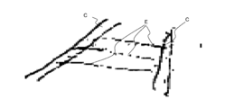
- a layered fiber E can be passed between the linear skeletons C to form a tangible body (see FIG. 7).
- a typical three-dimensional tangible body (filled G) can also be formed (see FIG. 8).
- the upper narrow mouth is open
- a divergent box-shaped tangible body in which the lower bottom surface is closed by laminating layer-constituting fibers.
- a tangible body such as a Suehiro box type tangible body is difficult to manufacture by the conventional FW method, and if a fixed formwork surrounded by plates is used, it is difficult to remove the mold after the filling has solidified.
- the method for producing a tangible body of the present invention can be produced without these difficulties.
- a method for laminating layer-constituting fibers a method in which wrinkles form wrinkles may be employed.
- a fiber supply device is provided inside the lattice-like linear skeleton as shown in FIG. While fixing the linear skeleton and rotating the supply port of the fiber supply device to the left and right, the layer constituent fibers adhere to the linear skeleton while adhering the layer constituent fibers to each other, While fixing the supply port of the fiber supply device and rotating the linear skeleton left and right, the layer constituting fibers may be adhered to each other while adhering the layer constituting fibers to the linear skeleton.
- a means for adhering the layer-constituting fibers and the linear skeleton can be employed.
- the method for producing a tangible body of the present invention includes the step 1 for forming a linear skeleton and the step 2 for forming a tangible body composed of fibers by attaching layer-forming fibers on the linear skeleton.
- step 1 and / or step 2 may be performed in the atmosphere, but may be performed in a space in which the influence of gravity is eliminated as much as possible in order to facilitate the arrangement of the linear skeleton and the layer-forming fibers. Good.
- Examples of the space from which the influence of gravity is eliminated include a space such as a rocket, a space filled with a medium such as a liquid having a high specific gravity, powder, or a viscous liquid.
- Examples of viscous liquids include viscous konjac aqueous solutions, thixotropic gel substances, and magnetizable fluids in which ferrite powder is dispersed. It should be noted that it is preferable that the filling material constituting the space from which the influence of gravity is eliminated is removed at the stage where the tangible body has been formed and reused if possible.
- a curable resin liquid that is incompatible with the medium may be dispersed, and the resin liquid may be cured to form a linear skeleton or a layer-forming fiber.
- the curable resin liquid is preferably energy curable from the viewpoint that it can be cured when necessary, and using an electromagnetic wave curable type such as infrared rays, an ultrasonic curable type, a thermosetting type, etc. It can be cured by applying ultrasonic waves or heat.
- Embodiment Example 1 Embodiment 1 of the present invention will be described with reference to FIG. (Omitted)
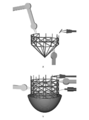
- A is a completed form of a tangible body.
- B is an aspect in the process of forming an egg-shaped tangible body.
- C is a fibrous linear skeleton.
- D is a fixed frame on the surface for fixing C, and a rectangular parallelepiped cylinder is formed by four perpendicular surfaces.
- Such a cylinder is only required to have a surface necessary for fixing C, and may be cylindrical, triangular, polygonal, or an unnecessary surface may be open.
- the surface may be opaque, but in the example, it is drawn to be transparent so that the internal work can be seen.
- E is a layer-forming fiber.
- F is a fiber supply device for layer-forming fibers.
- the layer forming fiber E is discharged from the nozzle N of the fiber supply device F having the nozzle N in accordance with discharge conditions set in advance so that the tangible body can be formed into an egg shape.
- the layer-forming fiber E forms a layer along the coordinates of the tangible body set in advance while adhering to the linear skeleton C stretched around at a predetermined position so that the tangible body can be formed into an egg shape.
- the ejection angle and the ejection speed during ejection are controlled by, for example, a computer.
- the layer-forming fiber E adheres to the linear skeleton C and forms a layer
- the linear skeleton C and the layer-forming fiber E are bonded and fixed together with an adhesive.
- the adhesive is bonded to the periphery of the layer-forming fiber E by an adhesive application means (not shown).
- the photocurable thermosetting adhesive may be cured by irradiating light when the layer-forming fibers E are laminated together, and the photocurable heat-curable adhesive may be cured by light irradiation and heating after the fiber constituent layer is formed.
- the curable adhesive may be cured.
- the layered fiber E is laminated to form a tangible body in a preset egg shape, and after the adhesive is cured, the linear skeleton C is removed from the tangible body, and the tangible body is taken out of the fixed frame D to manufacture. Complete.
- the materials and dimensions of C, D, and E, and the type of G and the method of F are determined in consideration of the mechanical properties and physicochemical properties of the tangible bodies that have been set.
- Embodiment Example 2 Embodiment 2 of the present invention will be described with reference to FIG.
- the computer graphics show how the filaments, which are the formed fibers, are bonded to the linear skeleton and rolled up.
- FIG. 6X shows a state in which only 1/3 of the tangible body is formed.
- FIG. 6Y shows a state where only 2/3 of the tangible body is formed.
- FIG. 6Z shows a state immediately before the formation of the tangible body is completed.
- the step 1 for forming the linear skeleton and the step 2 for forming the layer by adhering the fibers on the linear skeleton are performed in parallel.
- a tangible body for example, Large items such as exteriors of rockets, aircraft, tankers, railway vehicles and automobiles, Small and medium items such as rockets, aircraft, tankers, railway vehicles and automobile parts, Articles of human body scale such as clothing tools such as tools, boots, accessories, and medical tools such as artificial organs can be formed without using a fixed formwork.
Landscapes
- Chemical & Material Sciences (AREA)
- Engineering & Computer Science (AREA)
- Composite Materials (AREA)
- Mechanical Engineering (AREA)
- Moulding By Coating Moulds (AREA)
- Lining Or Joining Of Plastics Or The Like (AREA)
- Laminated Bodies (AREA)
Priority Applications (1)
| Application Number | Priority Date | Filing Date | Title |
|---|---|---|---|
| US14/412,141 US9259881B2 (en) | 2012-07-04 | 2013-07-04 | Method for producing a formed article comprised of a fiber |
Applications Claiming Priority (4)
| Application Number | Priority Date | Filing Date | Title |
|---|---|---|---|
| JP2012-150275 | 2012-07-04 | ||
| JP2012150275 | 2012-07-04 | ||
| JP2013-130968 | 2013-06-21 | ||
| JP2013130968A JP6166964B2 (ja) | 2012-07-04 | 2013-06-21 | 繊維で構成される有形体の製造方法 |
Publications (1)
| Publication Number | Publication Date |
|---|---|
| WO2014007324A1 true WO2014007324A1 (ja) | 2014-01-09 |
Family
ID=49882075
Family Applications (1)
| Application Number | Title | Priority Date | Filing Date |
|---|---|---|---|
| PCT/JP2013/068357 Ceased WO2014007324A1 (ja) | 2012-07-04 | 2013-07-04 | 繊維で構成される有形体の製造方法 |
Country Status (3)
| Country | Link |
|---|---|
| US (1) | US9259881B2 (https=) |
| JP (1) | JP6166964B2 (https=) |
| WO (1) | WO2014007324A1 (https=) |
Families Citing this family (1)
| Publication number | Priority date | Publication date | Assignee | Title |
|---|---|---|---|---|
| JP6298901B1 (ja) * | 2016-07-21 | 2018-03-20 | 株式会社ジャムコ | Cfrp部材及びラティス構造体 |
Citations (4)
| Publication number | Priority date | Publication date | Assignee | Title |
|---|---|---|---|---|
| JPS593063A (ja) * | 1982-06-29 | 1984-01-09 | 末松 大吉 | ガラス繊維枠を内蔵したセメント製品 |
| JPS5938011A (ja) * | 1982-08-27 | 1984-03-01 | 末松 大吉 | コンクリ−ト補強枠 |
| JPS615928A (ja) * | 1984-06-19 | 1986-01-11 | Toyota Motor Corp | 繊維強化樹脂構造体の製造方法 |
| JP2001501714A (ja) * | 1996-10-08 | 2001-02-06 | アールシーシー リージョナル コンパクト カーアーゲー | プラスチック成形品およびデザイン構造部材 |
Family Cites Families (10)
| Publication number | Priority date | Publication date | Assignee | Title |
|---|---|---|---|---|
| US2614058A (en) * | 1948-06-03 | 1952-10-14 | Richard J Francis | Methods of forming reinforced hollow plastic articles |
| FR2529240A1 (fr) | 1982-06-29 | 1983-12-30 | Toei Shoko | Produits en beton ou ciment comportant une armature |
| JPH0694621B2 (ja) * | 1985-11-29 | 1994-11-24 | 敷島紡績株式会社 | 複合材強化用の繊維構造体 |
| DE68929542D1 (de) | 1988-04-18 | 2006-01-19 | 3D Systems Inc | Stereolithografie mit verschiedenen Vektorabtastungsmoden |
| JPH07111017B2 (ja) * | 1989-02-20 | 1995-11-29 | 株式会社豊田自動織機製作所 | 三次元織物及びその製造方法 |
| US5585155A (en) * | 1995-06-07 | 1996-12-17 | Andersen Corporation | Fiber reinforced thermoplastic structural member |
| JP4715264B2 (ja) | 2005-03-25 | 2011-07-06 | 日産自動車株式会社 | フィラメントワインディング装置及び成形品の成形方法 |
| US8373657B2 (en) * | 2008-08-15 | 2013-02-12 | Qualcomm Incorporated | Enhanced multi-touch detection |
| WO2011143666A2 (en) * | 2010-05-14 | 2011-11-17 | Sigma-Tek, Llc | Covered composite lattice support structures and methods associated therewith |
| JP5655386B2 (ja) * | 2010-06-10 | 2015-01-21 | トヨタ自動車株式会社 | 繊維強化プラスチック成形体の製造方法 |
-
2013
- 2013-06-21 JP JP2013130968A patent/JP6166964B2/ja not_active Expired - Fee Related
- 2013-07-04 WO PCT/JP2013/068357 patent/WO2014007324A1/ja not_active Ceased
- 2013-07-04 US US14/412,141 patent/US9259881B2/en not_active Expired - Fee Related
Patent Citations (4)
| Publication number | Priority date | Publication date | Assignee | Title |
|---|---|---|---|---|
| JPS593063A (ja) * | 1982-06-29 | 1984-01-09 | 末松 大吉 | ガラス繊維枠を内蔵したセメント製品 |
| JPS5938011A (ja) * | 1982-08-27 | 1984-03-01 | 末松 大吉 | コンクリ−ト補強枠 |
| JPS615928A (ja) * | 1984-06-19 | 1986-01-11 | Toyota Motor Corp | 繊維強化樹脂構造体の製造方法 |
| JP2001501714A (ja) * | 1996-10-08 | 2001-02-06 | アールシーシー リージョナル コンパクト カーアーゲー | プラスチック成形品およびデザイン構造部材 |
Also Published As
| Publication number | Publication date |
|---|---|
| US9259881B2 (en) | 2016-02-16 |
| JP6166964B2 (ja) | 2017-07-19 |
| JP2014028514A (ja) | 2014-02-13 |
| US20150136300A1 (en) | 2015-05-21 |
Similar Documents
| Publication | Publication Date | Title |
|---|---|---|
| Yang et al. | Recent progress in biomimetic additive manufacturing technology: from materials to functional structures | |
| JP6808635B2 (ja) | 改良された機械的特性のための、硬化性追従材料を挿入することによる、付加製造技術で製造された複数の部分のスティッチング | |
| ES2894037T3 (es) | Procedimiento para fabricar una pieza de material compuesto | |
| US11975484B2 (en) | Cellular fabrication and apparatus for additive manufacturing | |
| US10406750B2 (en) | Fiber-reinforced 3D printing | |
| US10967569B2 (en) | Additive manufacturing system having interchangeable nozzle tips | |
| Sarabia-Vallejos et al. | Innovation in additive manufacturing using polymers: a survey on the technological and material developments | |
| JP6073087B2 (ja) | 繊維強化部品のダイレクトデジタル製造のための方法、装置、及び材料混合物 | |
| Dikshit et al. | Recent progress in 3D printing of fiber-reinforced composite and nanocomposites | |
| JP2020501957A (ja) | 複合乗物ボディ | |
| US10947356B2 (en) | Porous nanocomposite and related method | |
| JP2014188996A (ja) | ハニカムコアサンドイッチ構造体の修理方法および修理結果物 | |
| CA3020994A1 (en) | Cellular fabrication and apparatus for additive manufacturing | |
| US20180207866A1 (en) | Additive manufacturing system having in-situ reinforcement fabrication | |
| JP2017513742A (ja) | 積層体からなるパネルおよびその製造方法 | |
| JP6166964B2 (ja) | 繊維で構成される有形体の製造方法 | |
| EP3348401A1 (en) | Multi-part filaments for additive manufacturing and related systems and methods | |
| TWI491783B (zh) | 以具有z軸結構的複合層疊材料修補交通設施之方法及該複合層疊材料結構 | |
| Bourgeois | Toolless Out of Build Plane Manufacturing of Intricate Continuous Fiber Reinforced Thermoplastic Composites with a 3D Printing System | |
| CN106540420B (zh) | 球棒本体及其制法 | |
| US11103955B2 (en) | Component manufacture | |
| ES2995586T3 (en) | Method and apparatus for the construction of three-dimensional fibre-reinforced structures from a pre-existing object | |
| Kumar | Design, 3D Print and Analysis of Polymer Based Auxetic Core Structures | |
| Mohamed | Super-Composite: Carbon Fiber reinforced 3D Printed Tectonics | |
| CN104608385B (zh) | 一种3d打印造像的方法、设备及制品 |
Legal Events
| Date | Code | Title | Description |
|---|---|---|---|
| 121 | Ep: the epo has been informed by wipo that ep was designated in this application |
Ref document number: 13813040 Country of ref document: EP Kind code of ref document: A1 |
|
| WWE | Wipo information: entry into national phase |
Ref document number: 14412141 Country of ref document: US |
|
| NENP | Non-entry into the national phase |
Ref country code: DE |
|
| 122 | Ep: pct application non-entry in european phase |
Ref document number: 13813040 Country of ref document: EP Kind code of ref document: A1 |