WO2014007044A1 - 波長制御ヒーター - Google Patents
波長制御ヒーター Download PDFInfo
- Publication number
- WO2014007044A1 WO2014007044A1 PCT/JP2013/066336 JP2013066336W WO2014007044A1 WO 2014007044 A1 WO2014007044 A1 WO 2014007044A1 JP 2013066336 W JP2013066336 W JP 2013066336W WO 2014007044 A1 WO2014007044 A1 WO 2014007044A1
- Authority
- WO
- WIPO (PCT)
- Prior art keywords
- infrared
- filter surface
- temperature
- filter
- refrigerant
- Prior art date
- Legal status (The legal status is an assumption and is not a legal conclusion. Google has not performed a legal analysis and makes no representation as to the accuracy of the status listed.)
- Ceased
Links
Images





Classifications
-
- H—ELECTRICITY
- H05—ELECTRIC TECHNIQUES NOT OTHERWISE PROVIDED FOR
- H05B—ELECTRIC HEATING; ELECTRIC LIGHT SOURCES NOT OTHERWISE PROVIDED FOR; CIRCUIT ARRANGEMENTS FOR ELECTRIC LIGHT SOURCES, IN GENERAL
- H05B1/00—Details of electric heating devices
- H05B1/02—Automatic switching arrangements specially adapted to apparatus ; Control of heating devices
- H05B1/0227—Applications
Definitions
- the present invention relates to a wavelength control heater.
- Patent Document 1 As an infrared heater, a rod-shaped heating element made of carbon or silicon carbide that emits infrared rays when heated, and a light-transmitting property in which the heating element is hermetically accommodated What is provided with a cylindrical protective tube made of alumina ceramics is known.
- This protective tube has a total transmittance of electromagnetic waves having a wavelength of 0.4 to 6 ⁇ m of 80% or more.
- the present invention has been made to solve such a problem, and has as its main object to provide a plurality of infrared heating environments having different spectra with a single infrared heater.
- the wavelength control heater of the present invention employs the following means in order to achieve the above-mentioned main purpose.
- the wavelength control heater of the present invention is A heating element that emits infrared when heated, When the temperature is lower than a predetermined threshold, the infrared transmittance is high, and when the temperature is higher than the threshold, the filter surface has a property of decreasing the infrared transmittance; Temperature adjusting means for adjusting the temperature of the filter surface; Setting means for selecting and setting the type of infrared rays emitted from the wavelength control heater to the outside from options including the first infrared ray and the second infrared ray; When the first infrared ray is set, the temperature adjusting means is controlled so that the temperature of the filter surface is lower than the threshold value. When the second infrared ray is set, Control means for controlling the temperature adjusting means so that the temperature of the filter surface is higher than the threshold and the filter surface becomes the second infrared radiation source; It is equipped with.
- the heating element itself is kept at a relatively high temperature so that the radiation energy per unit area is large and infrared rays in a short wavelength region can be emitted.
- the temperature adjusting means is controlled so that the temperature of the filter surface is lower than the threshold value. Then, the infrared transmittance of the filter surface is increased. As a result, most of the infrared rays emitted from the heating element are transmitted to the outside through the filter surface, which becomes the main radiation source when the first infrared ray is set.
- the temperature adjusting means is controlled so that the temperature of the filter surface becomes higher than the threshold value. Then, the filter surface has a low infrared transmittance, and the infrared rays emitted from the heating element are not easily transmitted through the filter surface, and the process of repeatedly reflecting and absorbing radiation between the heating element and the filter surface is repeated. As a result, the temperature of the filter surface rises. As a result, the main radiation surface is converted from the heating element to the filter surface, and the infrared radiation emitted outward from the filter surface becomes the main radiation source to the outside when the second infrared radiation is set. .
- the temperature of the filter surface needs to be adjusted so as to finally have a temperature on the radiation spectrum in the wavelength range assumed for the second infrared ray.
- the first infrared ray has a spectrum peak in the near infrared region (eg, 0.7 to 3 ⁇ m), and the second infrared ray has a spectrum peak in the far infrared region (eg, 4 to 8 ⁇ m). Also good.
- the heating element temperature serving as the first infrared light source is 700 to 1500 ° C.
- the filter surface temperature serving as the second infrared light source is approximately 250 to 450 ° C.
- the wavelength control heater of the present invention further includes an infrared transmission surface disposed on at least one of the inside and the outside of the filter surface, and a refrigerant flow path formed between the filter surface and the infrared transmission surface.
- the temperature adjusting means may adjust at least one of a flow rate and a temperature of the refrigerant flowing through the refrigerant flow path. Since the refrigerant flow path formed between the filter surface and the infrared transmission surface is in contact with the filter surface, the temperature of the filter surface can be adjusted by adjusting at least one of the flow rate and temperature of the refrigerant flowing through the refrigerant flow channel. Can be controlled relatively easily.
- the infrared transmission surface is disposed in two layers on the outside of the filter surface, and the coolant channel is also formed between the infrared transmission surfaces disposed in two layers on the outside of the filter surface. Also good. Since the refrigerant flow path between the infrared transmitting surfaces arranged in two layers on the outside of the filter surface is in contact with the outside air, the surface temperature of the wavelength control heater can be adjusted by adjusting the flow rate of the refrigerant flowing through the refrigerant flow path. Can be lowered. For example, when an object containing an organic solvent is dried, vapor of the organic solvent exists around the wavelength control heater, but the surface temperature of the wavelength control heater can be lowered, so that safety is improved. high.
- the infrared transmission surface is disposed in one layer inside the filter surface and two layers outside the filter surface, and the refrigerant flow path includes the filter surface and an infrared transmission surface arranged inside the filter surface.
- the control surface is formed between the filter surface and the infrared transmission surface disposed in the first layer outside the filter surface and between the infrared transmission surfaces disposed in two layers outside the filter surface.
- the means When the first infrared ray is set as the type of the infrared ray, the means includes a refrigerant passage between the filter surface and an infrared ray transmitting surface arranged inside the filter surface, the filter surface, The temperature adjusting means is controlled so that the refrigerant flows through the refrigerant passage between the infrared ray transmitting surface arranged on the first layer outside the filter surface, and the second infrared ray is set as the infrared ray type. If it is, the refrigerant in the refrigerant passage formed between the infrared transmission faces which are arranged two layers on the outside of the filter surface may control the temperature regulating means so as to flow. In this way, the temperature of the filter surface can be made relatively easily below the threshold, or the temperature of the filter surface can be made higher than the threshold and the filter surface can be an infrared radiation source.
- FIG. 2 is an explanatory diagram of a wavelength control heater 10.
- FIG. FIG. 2 is a cross-sectional view taken along the line AA in FIG. It is a flowchart of a wavelength control routine.
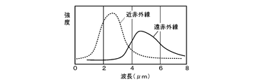
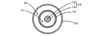
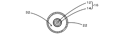
- FIG. 4 is an explanatory diagram showing how refrigerant flows through the first to third flow paths 31 to 33 of the wavelength control heater 10, where (a) shows near infrared rays and (b) shows a case where far infrared rays are outputted. It is a graph which shows the wavelength characteristic of a near infrared ray and a far infrared ray. It is sectional drawing of other embodiment. It is sectional drawing of other embodiment. It is sectional drawing of other embodiment. It is sectional drawing of other embodiment. It is sectional drawing of other embodiment. It is sectional drawing of other embodiment. It is sectional drawing of other embodiment. It is sectional drawing of other embodiment. It is sectional drawing of other embodiment. It is sectional drawing of other embodiment. It is sectional drawing of other embodiment. It is
- FIG. 1 is an explanatory view of the wavelength control heater 10
- FIG. 2 is a cross-sectional view taken along the line AA in FIG.
- the cross section shown in FIG. 1 is a surface cut so as to pass through the center line of the heater body 12.
- the wavelength control heater 10 is an infrared heater that can switch between outputting near infrared rays and outputting far infrared rays.
- near-infrared means infrared having a wavelength range of about 0.7 to 3 ⁇ m
- far-infrared means infrared having a wavelength range of about 4 to 8 ⁇ m.
- the wavelength control heater 10 includes a heater body 16 formed so that an inner tube 14 surrounds a tungsten filament 12, a filter tube 18 formed so as to surround the heater body 16, and an outer side of the filter tube 18.
- the first and second outer tubes 22 and 24 are provided in two layers, and caps 40 are attached to both ends thereof.
- the space between the inner tube 14 and the filter tube 18, the space between the filter tube 18 and the first outer tube 22, and the space between the first outer tube 22 and the second outer tube 24 are respectively refrigerant (here The first flow path 31, the second flow path 32, and the third flow path 33 can circulate air).
- the wavelength control heater 10 also includes a temperature sensor 26 that detects the temperature of the filter tube 18, an operation panel 28 for performing various setting inputs, and the temperature of the filter tube 18 according to the type of infrared that has been set and input. And a controller 60 for controlling.
- the heater body 16 is supported at both ends by holders 46 arranged inside the cap 40.
- the heater body 16 emits infrared rays having a peak wavelength shorter than 3 ⁇ m when power is supplied from the power supply source 50 to the filament 12 and the filament 12 is heated to 700 ° C. or higher.
- the inside of the inner tube 14 is in a vacuum atmosphere or a halogen atmosphere.
- the electric wiring 12 a connected to the filament 12 is drawn out to the outside airtightly via a wiring drawing portion 48 provided in the cap 40, and is connected to the power supply source 50.
- the inner tube 14 is made of an infrared transmitting material.
- infrared transmitting materials include germanium, silicon, sapphire, calcium fluoride, barium fluoride, zinc selenide, zinc sulfide, chalcogenide glass, transparent alumina ceramics, and quartz capable of transmitting infrared rays up to about 6 ⁇ m. Glass etc. are mentioned.
- the filter tube 18 is formed by forming a film 18b of a thermochromic material on the outer surface of the tube 18a formed of the above-described infrared transmitting material by using a film forming method such as sputtering or CVD.
- the thermochromic material film 18b may be formed not on the outer surface of the tube 18a but on the inner surface, or on both the outer surface and the inner surface of the tube 18a. However, considering the ease of film formation, it is preferable to form it on the outer surface of the tube 18a.
- a thermochromic material is a material whose infrared transmittance changes greatly at a certain temperature.
- thermochromic materials include transition metal oxides such as vanadium oxide and titanium oxide. Among these, vanadium oxide having a large change in infrared transmittance with respect to temperature is preferable.
- the temperature threshold for vanadium is about 68 ° C. Further, the threshold value can be changed by adding elements such as Mo, W, and Nb to these transition metal oxides.
- Other thermochromic materials include hydrides of rare earth metals such as yttrium and lanthanum, hydrides of alloys of rare earth metals such as gadolinium and magnesium, and hydrides of magnesium / nickel alloys.
- the first and second outer tubes 22 and 24 are tubes made of the above-described infrared transmitting material.
- the cap 40 is formed by integrally molding a disc-shaped lid 44 and three cylindrical portions 41, 42, and 43 that are concentrically provided on the lid 44 and have different radii.
- the left and right ends of the filter tube 18 are fixed to the innermost cylindrical portion 41
- the left and right ends of the first outer tube 22 are fixed to the middle cylindrical portion 42
- the left and right ends of the second outer tube 24 are the outermost ends. It is fixed to the cylindrical portion 43.
- the first flow path 31 is a space between the inner pipe 14 and the filter pipe 18, and the refrigerant can flow through the first vent 51 provided in the innermost cylindrical portion 41 of the cap 40.
- the second flow path 32 is a space between the filter pipe 18 and the first outer pipe 22, and allows refrigerant to flow through the second vent 52 provided in the cap 40.
- the refrigerant flowing through the first and second flow paths 31 and 32 cools the filter tube 18 by directly contacting the filter tube 18 and removing heat.
- the third flow path 33 is a space between the first outer tube 22 and the second outer tube 24, and allows refrigerant to flow through the third vent 53 provided in the cap 40.
- the refrigerant flowing through the third flow path 33 serves to lower the temperature of the outer surface of the wavelength control heater 10.
- the controller 60 is configured as a microprocessor centered on a CPU.
- the controller 60 inputs the temperature of the filter tube 18 detected by the temperature sensor 26 that is a thermocouple, and inputs information set by the operator on the operation panel 28.
- the controller 60 outputs a control signal to the first on-off valve 71 and the first flow rate adjustment valve 81 provided in the middle of the pipe connecting the refrigerant supply source 70 and the first vent 51, or supplies the refrigerant supply source
- a control signal is output to the second on-off valve 72 and the second flow rate adjustment valve 82 provided in the middle of the pipe connecting the 70 and the second vent 52, or the refrigerant supply source 70 and the third vent 53 are connected.
- a control signal is output to the third on-off valve 73 and the third flow rate adjustment valve 83 provided in the middle of the pipe to be connected. Further, the controller 60 outputs a control signal for adjusting the magnitude of the power supplied from the power supply source 50 to the filament 12 to the power supply source 50.
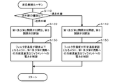
- the controller 60 executes the wavelength control routine shown in FIG. 3
- the wavelength control routine program is stored in a ROM (not shown) of the controller 60.
- vanadium oxide temperature threshold of about 68 ° C.
- the temperature of the filament 12 shall be 1000 degreeC.
- the controller 60 When the wavelength control routine is started, the controller 60 first inputs setting information of the operation panel 28, and determines whether the type of infrared is set to near infrared or far infrared (step S110). . And if near infrared rays were set up, the 1st and 2nd on-off valves 71 and 72 will be opened, and the 3rd on-off valve 73 will be closed (Step S120). As a result, the refrigerant can flow through the first and second flow paths 31 and 32, and the refrigerant cannot flow through the third flow path 33. The state at this time is shown in FIG. In the figure, hatching indicates the refrigerant.
- the controller 60 controls the first and second flow rate adjusting valves 81 and 82 and the power supply source so that the temperature of the filter tube 18 input from the temperature sensor 26 is 68 ° C. or less which is the temperature threshold of vanadium oxide. 50 is controlled (step S130). For example, when the temperature of the filter tube 18 exceeds 68 ° C., the first and second flow rate adjusting valves 81 and 82 are adjusted so that the refrigerant flow rate supplied to the first and second flow paths 31 and 32 increases. To do. As a result, the temperature of the filter tube 18 falls below the threshold value.
- the power supply source 50 is adjusted so that the power supplied to the filament 12 is reduced. Thereby, since the temperature of the filament 12 falls, the temperature of the filter tube 18 also falls. However, the lower limit of the temperature of the filament 12 is 700 ° C. Since the first and second flow paths 31 and 32 are in contact with the filter tube 18 and have a good cooling efficiency by the refrigerant, the filter tube 18 is usually sufficient without reducing the power supplied to the filament 12. The temperature drops.
- the temperature of the filter tube 18 is set to 68 ° C. or lower.
- vanadium oxide which is a thermochromic material, has a high infrared transmittance (about 50 to 60%). That is, the infrared transmittance of the filter tube 18 is increased. Part of the infrared rays once absorbed by the filter tube 18 is removed to the outside together with the refrigerant by heat exchange with the refrigerant. Further, since the inner tube 14 and the first and second outer tubes 22 and 24 are formed of an infrared transmitting material, the infrared transmittance is high.
- the infrared rays emitted from the filament 12 pass through the inner tube 14, the filter tube 18, the first and second outer tubes 22 and 24, and are emitted from the wavelength control heater 10 to the outside.
- the filament 12 has a temperature of 700 ° C. or higher, it emits infrared rays having a spectrum shifted to the shorter wavelength side as shown by the dotted line in FIG. As is apparent from FIG. 5, most of the emitted infrared light is in the near infrared region.
- the spectrum emitted from the wavelength control heater 10 to the outside is almost the same.
- step S110 if far infrared rays have been set in step S110, the first and second on-off valves 71 and 72 are closed, and the third on-off valve 73 is opened (step S140). As a result, the refrigerant cannot flow through the first and second flow paths 31 and 32, and the refrigerant can flow through the third flow path 33.
- the state at this time is shown in FIG.
- the controller 60 receives the temperature of the filter tube 18 input from the temperature sensor 26 at 300 ° C. ⁇ ⁇ ° C. ( ⁇ is a numerical value indicating an allowable temperature range, for example, a range of 1 to 10).
- the third flow rate adjustment valve 82 and the power supply source 50 are controlled (step S150).
- the temperature of the filter tube 18 becomes 68 ° C. or higher due to the heat of the filament 12, the infrared transmittance of vanadium oxide is lowered (about 10 to 20%), so that the infrared rays emitted from the filament 12 are not easily transmitted through the filter tube 18.
- the temperature of the filter tube 18 is likely to rise.
- the temperature of the filter tube 18 exceeds 300 ° C.
- the third flow rate adjustment valve 83 is adjusted so that the flow rate of the refrigerant supplied to the third flow path 33 is increased, and the temperature of the filter tube 18 is 300.
- the third flow rate adjusting valve 83 is adjusted so that the flow rate of the refrigerant supplied to the third flow path 33 is decreased, and the temperature of the filter tube 18 is within 300 ° C. ⁇ ⁇ ° C. In this case, the third flow rate adjustment valve 83 maintains that state. If the temperature of the filter tube 18 cannot be kept at 300 ° C. ⁇ ⁇ ° C.
- the power supply source 50 is adjusted so that the power supplied to the filament 12 increases or decreases. As a result, the temperature of the filament 12 rises or falls, and as a result, the temperature of the filter tube 18 also rises and falls due to the influence.
- the temperature of the filter tube 18 is set to 300 ° C. ⁇ ⁇ ° C.
- the wavelength control heater 10 emits far infrared radiation having a spectrum indicated by a solid line in FIG. Since the temperature is as low as 300 ° C. ⁇ ⁇ ° C., the peak wavelength shifts to the long wavelength side as compared with the wavelength characteristic indicated by the dotted line. As is clear from FIG. 5, most of the emitted infrared light is in the far infrared region.
- the peak intensity is lower than that of the near-infrared ray indicated by a dotted line, but the radiation area is much larger in the filter tube 18 than in the filament 12, so that the energy is There is no big difference between the two.
- the filament 12 of this embodiment corresponds to the heating element of the present invention
- the filter tube 18 corresponds to the filter surface
- the operation panel 28 corresponds to the setting means (the near infrared ray is the first infrared ray, the far infrared ray is the second infrared ray).
- the controller 60 corresponds to temperature adjusting means and control means.
- the inner tube 14 and the first and second outer tubes 22 and 24 correspond to infrared transmission surfaces
- the first to third channels 31 to 33 correspond to refrigerant channels.
- the wavelength control heater 10 it is possible to provide a plurality of infrared heating environments having different spectra with a single infrared heater.
- the temperature of the filter pipe 18 can be adjusted by adjusting the flow rate of the refrigerant flowing through the first and second flow paths 31 and 32. It can be controlled relatively easily.
- the refrigerant flowing through the third flow path 33 can be lowered (for example, 150 ° C. or 200 ° C.) by adjusting the flow rate of.
- the surface temperature of the wavelength control heater 10 is set below the ignition point. Because it is easy to maintain, safety is high.
- the controller 60 supplies a refrigerant whose flow rate is adjusted to the first and second flow paths 31 and 32 when the filter pipe 18 is set to 68 ° C. or lower, and the filter pipe 18 is set to 300 ° C. ⁇ ⁇ ° C.
- a solvent whose flow rate is adjusted is supplied to the third flow path 33.
- the temperature of the filter tube 18 can be relatively easily set to a temperature lower than the threshold value, or higher than the threshold value, so that the filter tube 18 becomes a far infrared radiation source.
- the refrigerant when the temperature of the filter tube 18 is set to 68 ° C. or lower, the refrigerant is allowed to flow through both the first and second flow paths 31 and 32. However, the refrigerant may be allowed to flow through one of them. However, the coolant may also flow through the third flow path 33. In addition, when the temperature of the filter tube 18 is set to 300 ° C. ⁇ ⁇ ° C., the refrigerant is passed through the third flow path 33, but instead of or in addition, at least one of the first flow path 31 and the second flow path 32. A refrigerant may be flowed through.
- the temperature of the filter tube 18 when adjusting the temperature of the filter tube 18, it may be determined as appropriate to which of the first to third flow paths 31 to 33 the refrigerant flows. Moreover, although the flow volume of the refrigerant
- W tungsten
- Mo molybdenum
- Ta molybdenum
- Fe—Cr—Al alloy molybdenum
- Ni—Cr alloy molybdenum
- the heating element a number of microcavities that amplify a predetermined wavelength region (for example, 5 to 6 ⁇ m) may be formed on the surface. In order to amplify the wavelength region of 5 to 6 ⁇ m, for example, the horizontal and vertical widths of the microcavity may be 3 to 3.5 ⁇ m and the depth is 2.5 to 4 ⁇ m.
- a high-resolution resist such as polymethyl methacrylate (PMMA) is first spin-coated on the surface of a belt-shaped metal plate made of a heating element material, and the resist is patterned by direct electron beam drawing. Then, there is a method of forming a microcavity by dry etching using it as a mask.
- PMMA polymethyl methacrylate
- the first and second outer tubes 22 and 24 are arranged on the outside of the filter tube 18 so as to form two layers.
- the first flow path 31 is between the inner pipe 14 and the filter pipe 18 of the heater body 16
- the second flow path 32 is between the filter pipe 18 and the first outer pipe 22.
- the inner tube 14 is used as a filter tube, and the first outer tube 22 and the second outer tube 24 are provided outside thereof. You may arrange
- the second flow path 32 is between the inner pipe 14 and the first outer pipe 22 of the heater body 16, and the third flow path 33 is between the first outer pipe 22 and the second outer pipe 24.
- the inner tube 14 is used as a filter tube, and only one first outer tube 22 is disposed on the outer side. Also good.
- a space between the inner tube 14 and the first outer tube 22 of the heater body 16 is the second flow path 32. 6 to 8, control is performed so that the temperature of the filter tube becomes the target temperature by appropriately selecting the flow path or changing the flow rate of the refrigerant according to the target temperature of the filter tube. For example, in FIG.
- the second flow path 32 may be closed and the flow rate adjusted refrigerant may be supplied to the third flow path 33.
- the refrigerant whose flow rate is adjusted is supplied to the second flow path 32, and the inner tube 14 is heated to 300 ° C. ⁇ ⁇ ° C. If so, the second flow path 32 may be closed.
- FIG. 8 it is preferable to use when there is no ignitable component around the wavelength control heater.
- a plurality of tubes are arranged concentrically, but other configurations may be used.
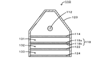
- a protective tube 120 having a hexagonal cross section with a bottom opened, a heating element 112 disposed in the protective tube 120, and the heating element
- a plurality of surfaces 114, 118, 122, and 124 arranged from 112 to the bottom surface of the protective tube 120 may be provided.
- the plurality of surfaces 114, 118, 122, and 124 are the inner transmission surface 114, the filter surface 118, the first outer transmission surface 122, and the second outer transmission surface 124 from the heating element side to the bottom surface, respectively.
- the inner tube 14, the filter tube 18, the first outer tube 22, and the second outer tube 24 are formed of the same material.
- the filter surface 118 is obtained by forming a thermochromic material film 118b on one surface of a plate material 118a made of an infrared transmitting material. Since the film 118b is formed by sputtering, CVD, or the like, a plate material is easier to form than a tube.
- a space (space in which the heating element 112 is disposed) partitioned by the inner transmission surface 114 in the protective tube 120 is a vacuum atmosphere or a halogen atmosphere.
- the first flow path 131 is between the inner transmission surface 114 and the filter surface 118
- the second flow path 132 is between the filter surface 118 and the first outer transmission surface 122
- the first outer transmission surface 122 and the second outer surface is between the transmission surface 124.
- the controller executes the wavelength control routine shown in FIG. 4 to emit infrared rays in different wavelength regions to the outside of the wavelength control heater 110.
- the configuration in which a plurality of tubes are arranged concentrically as shown in FIGS. 6 to 8 may be changed to a configuration using a plurality of surfaces as shown in FIG.
- air is used as the refrigerant.
- an inert gas such as nitrogen gas or argon gas may be used instead of air, or a liquid such as oil or ionic liquid may be used.
- a filter tube 118 having a cross section shown in FIG. 10 may be used.
- the filter tube 118 has a fin-like process on the outer surface of the tube 118a.
- a thermochromic film 118b is formed on the outer surface of the tube 118a. If this filter tube 118 is used, the radiation area to the outer surface increases, so that the cooling efficiency is improved.
- the present invention relates to industries that require heating and drying, such as the battery industry that manufactures electrode coatings for lithium ion secondary batteries, the ceramic industry that manufactures ceramic laminates composed of two layers of ceramic sintered bodies, and optical film products. It can be used for the film industry to manufacture.
Landscapes
- Resistance Heating (AREA)
- Control Of Resistance Heating (AREA)
Description
加熱されると赤外線を放出する発熱体と、
温度が所定の閾値より低いと赤外線透過率が高くなり、温度が前記閾値より高いと赤外線透過率が低くなる性質を有するフィルタ面と、
前記フィルタ面の温度を調節する温度調節手段と、
前記波長制御ヒーターから外部へ放出される赤外線の種類を、第1の赤外線及び第2の赤外線を含む選択肢の中から選択して設定する設定手段と、
前記第1の赤外線が設定されている場合には、前記フィルタ面の温度が前記閾値より低くなるように前記温度調節手段を制御し、前記第2の赤外線が設定されている場合には、前記フィルタ面の温度が前記閾値より高く且つ該フィルタ面が前記第2の赤外線の放射源となるように前記温度調節手段を制御する制御手段と、
を備えたものである。
Claims (5)
- 加熱されると赤外線を放出する発熱体と、
温度が所定の閾値より低いと赤外線透過率が高くなり、温度が前記閾値より高いと赤外線透過率が低くなる性質を有するフィルタ面と、
前記フィルタ面の温度を調節する温度調節手段と、
前記波長制御ヒーターから外部へ放出される赤外線の種類を、第1の赤外線及び第2の赤外線を含む選択肢の中から選択して設定する設定手段と、
前記赤外線の種類として前記第1の赤外線が設定されている場合には、前記フィルタ面の温度が前記閾値より低くなるように前記温度調節手段を制御し、前記赤外線の種類として前記第2の赤外線が設定されている場合には、前記フィルタ面の温度が前記閾値より高く且つ該フィルタ面が前記第2の赤外線の放射源となるように前記温度調節手段を制御する制御手段と、
を備えた波長制御ヒーター。 - 請求項1に記載の波長制御ヒーターであって、
前記フィルタ面の内側及び外側の少なくとも一方に配置された赤外線透過面と、
前記フィルタ面と前記赤外線透過面との間に形成された冷媒流路と、
を備え、
前記温度調節手段は、前記冷媒流路に流す冷媒の流量を調節するものである、
波長制御ヒーター。 - 前記赤外線透過面は、前記フィルタ面の外側に二層配置され、
前記冷媒流路は、前記フィルタ面の外側に二層配置された前記赤外線透過面同士の間にも形成されている、
請求項2に記載の波長制御ヒーター。 - 前記赤外線透過面は、前記フィルタ面の内側に一層、前記フィルタ面の外側に二層配置され、
前記冷媒流路は、前記フィルタ面と前記フィルタ面の内側に配置された赤外線透過面との間、前記フィルタ面と前記フィルタ面の外側の一層目に配置された赤外線透過面との間及び前記フィルタ面の外側に二層配置された前記赤外線透過面同士の間に形成され、
前記制御手段は、前記赤外線の種類として前記第1の赤外線が設定されている場合には、前記フィルタ面と前記フィルタ面の内側に配置された赤外線透過面との間の冷媒通路と、前記フィルタ面と前記フィルタ面の外側の一層目に配置された赤外線透過面との間の冷媒通路とに冷媒が流通するように前記温度調節手段を制御し、前記赤外線の種類として前記第2の赤外線が設定されている場合には、前記フィルタ面の外側に二層配置された前記赤外線透過面同士の間に形成された冷媒通路に冷媒が流通するように前記温度調節手段を制御する、
請求項3に記載の波長制御ヒーター。 - 前記第1の赤外線はスペクトル上のピークが近赤外域にあるものであり、前記第2の赤外線はスペクトル上のピークが遠赤外域にあるものである、
請求項1~4のいずれか1項に記載の波長制御ヒーター。
Priority Applications (1)
| Application Number | Priority Date | Filing Date | Title |
|---|---|---|---|
| JP2013547431A JP5451953B1 (ja) | 2012-07-06 | 2013-06-13 | 波長制御ヒーター |
Applications Claiming Priority (2)
| Application Number | Priority Date | Filing Date | Title |
|---|---|---|---|
| JP2012152312 | 2012-07-06 | ||
| JP2012-152312 | 2012-07-06 |
Publications (1)
| Publication Number | Publication Date |
|---|---|
| WO2014007044A1 true WO2014007044A1 (ja) | 2014-01-09 |
Family
ID=49881804
Family Applications (1)
| Application Number | Title | Priority Date | Filing Date |
|---|---|---|---|
| PCT/JP2013/066336 Ceased WO2014007044A1 (ja) | 2012-07-06 | 2013-06-13 | 波長制御ヒーター |
Country Status (3)
| Country | Link |
|---|---|
| JP (1) | JP5451953B1 (ja) |
| TW (1) | TW201406193A (ja) |
| WO (1) | WO2014007044A1 (ja) |
Cited By (1)
| Publication number | Priority date | Publication date | Assignee | Title |
|---|---|---|---|---|
| WO2019111736A1 (ja) * | 2017-12-08 | 2019-06-13 | 東京エレクトロン株式会社 | 光学装置、測定装置、接合システムおよび測定方法 |
Citations (4)
| Publication number | Priority date | Publication date | Assignee | Title |
|---|---|---|---|---|
| JPS6129087A (ja) * | 1984-07-18 | 1986-02-08 | 株式会社日立ホームテック | 遠赤外線ヒ−タ |
| JPH0634272A (ja) * | 1992-03-23 | 1994-02-08 | Ngk Insulators Ltd | 遠赤外線加熱装置 |
| JPH10259955A (ja) * | 1997-03-19 | 1998-09-29 | Komatsu Ltd | 流体温度制御装置 |
| JP2005354511A (ja) * | 2004-06-11 | 2005-12-22 | Noritsu Koki Co Ltd | フィルムスキャナ |
-
2013
- 2013-06-13 JP JP2013547431A patent/JP5451953B1/ja active Active
- 2013-06-13 WO PCT/JP2013/066336 patent/WO2014007044A1/ja not_active Ceased
- 2013-06-18 TW TW102121474A patent/TW201406193A/zh unknown
Patent Citations (4)
| Publication number | Priority date | Publication date | Assignee | Title |
|---|---|---|---|---|
| JPS6129087A (ja) * | 1984-07-18 | 1986-02-08 | 株式会社日立ホームテック | 遠赤外線ヒ−タ |
| JPH0634272A (ja) * | 1992-03-23 | 1994-02-08 | Ngk Insulators Ltd | 遠赤外線加熱装置 |
| JPH10259955A (ja) * | 1997-03-19 | 1998-09-29 | Komatsu Ltd | 流体温度制御装置 |
| JP2005354511A (ja) * | 2004-06-11 | 2005-12-22 | Noritsu Koki Co Ltd | フィルムスキャナ |
Cited By (2)
| Publication number | Priority date | Publication date | Assignee | Title |
|---|---|---|---|---|
| WO2019111736A1 (ja) * | 2017-12-08 | 2019-06-13 | 東京エレクトロン株式会社 | 光学装置、測定装置、接合システムおよび測定方法 |
| JPWO2019111736A1 (ja) * | 2017-12-08 | 2021-01-14 | 東京エレクトロン株式会社 | 光学装置、測定装置、接合システムおよび測定方法 |
Also Published As
| Publication number | Publication date |
|---|---|
| JPWO2014007044A1 (ja) | 2016-06-02 |
| JP5451953B1 (ja) | 2014-03-26 |
| TW201406193A (zh) | 2014-02-01 |
Similar Documents
| Publication | Publication Date | Title |
|---|---|---|
| TWI520654B (zh) | Coating drying furnace | |
| JP6225117B2 (ja) | 赤外線加熱装置及び乾燥炉 | |
| JP4565159B2 (ja) | 温度定点セル、温度定点装置および温度計校正方法 | |
| JP5775224B2 (ja) | 赤外線加熱ユニット,赤外線加熱装置及び乾燥装置 | |
| TW201447207A (zh) | 含噴嘴之加熱器及乾燥爐 | |
| TW201510451A (zh) | 乾燥爐 | |
| JP5567390B2 (ja) | 可視光源 | |
| JP5451953B1 (ja) | 波長制御ヒーター | |
| JP2009117237A (ja) | フィラメントランプおよび光照射式加熱処理装置 | |
| JP2016040496A (ja) | 赤外線処理装置 | |
| JP2013206606A (ja) | 赤外線ヒーター | |
| JP5469285B1 (ja) | 赤外線ヒーター | |
| US9252006B2 (en) | Incandescent bulb, filament, and method for manufacturing filament | |
| US20200110252A1 (en) | Infrared light radiation device | |
| EP3787372A1 (en) | Infrared radiation device | |
| JP4329629B2 (ja) | エキシマランプ | |
| CN103065924A (zh) | 光照射装置、光照射方法、金属卤化物灯 | |
| JP2015138638A (ja) | 赤外光源 | |
| JP6625902B2 (ja) | 発光体、フィラメント、フィラメントを用いた装置、および、白熱電球 | |
| JP6293509B2 (ja) | 赤外線ヒーター及び赤外線ヒーターユニット | |
| JP6625903B2 (ja) | 発光体、フィラメント、フィラメントを用いた装置、および、白熱電球 | |
| JP2021157961A (ja) | 熱輻射光源 | |
| JP2021150190A (ja) | 熱輻射光源 | |
| Hunt et al. | A 1m diameter image furnace using a vortex stabilized argon arc | |
| JP2006156224A (ja) | 放射体および当該放射体を備えた装置 |
Legal Events
| Date | Code | Title | Description |
|---|---|---|---|
| ENP | Entry into the national phase |
Ref document number: 2013547431 Country of ref document: JP Kind code of ref document: A |
|
| 121 | Ep: the epo has been informed by wipo that ep was designated in this application |
Ref document number: 13812598 Country of ref document: EP Kind code of ref document: A1 |
|
| WWE | Wipo information: entry into national phase |
Ref document number: IDP00201407576 Country of ref document: ID |
|
| NENP | Non-entry into the national phase |
Ref country code: DE |
|
| 122 | Ep: pct application non-entry in european phase |
Ref document number: 13812598 Country of ref document: EP Kind code of ref document: A1 |