WO2014006784A1 - 撮像装置及び画像処理方法 - Google Patents
撮像装置及び画像処理方法 Download PDFInfo
- Publication number
- WO2014006784A1 WO2014006784A1 PCT/JP2012/084088 JP2012084088W WO2014006784A1 WO 2014006784 A1 WO2014006784 A1 WO 2014006784A1 JP 2012084088 W JP2012084088 W JP 2012084088W WO 2014006784 A1 WO2014006784 A1 WO 2014006784A1
- Authority
- WO
- WIPO (PCT)
- Prior art keywords
- color
- filter
- phase difference
- pixels
- image
- Prior art date
- Legal status (The legal status is an assumption and is not a legal conclusion. Google has not performed a legal analysis and makes no representation as to the accuracy of the status listed.)
- Ceased
Links
Images









Classifications
-
- H—ELECTRICITY
- H04—ELECTRIC COMMUNICATION TECHNIQUE
- H04N—PICTORIAL COMMUNICATION, e.g. TELEVISION
- H04N23/00—Cameras or camera modules comprising electronic image sensors; Control thereof
- H04N23/60—Control of cameras or camera modules
- H04N23/67—Focus control based on electronic image sensor signals
- H04N23/672—Focus control based on electronic image sensor signals based on the phase difference signals
-
- H—ELECTRICITY
- H04—ELECTRIC COMMUNICATION TECHNIQUE
- H04N—PICTORIAL COMMUNICATION, e.g. TELEVISION
- H04N23/00—Cameras or camera modules comprising electronic image sensors; Control thereof
- H04N23/60—Control of cameras or camera modules
- H04N23/63—Control of cameras or camera modules by using electronic viewfinders
- H04N23/631—Graphical user interfaces [GUI] specially adapted for controlling image capture or setting capture parameters
- H04N23/632—Graphical user interfaces [GUI] specially adapted for controlling image capture or setting capture parameters for displaying or modifying preview images prior to image capturing, e.g. variety of image resolutions or capturing parameters
-
- H—ELECTRICITY
- H04—ELECTRIC COMMUNICATION TECHNIQUE
- H04N—PICTORIAL COMMUNICATION, e.g. TELEVISION
- H04N23/00—Cameras or camera modules comprising electronic image sensors; Control thereof
- H04N23/80—Camera processing pipelines; Components thereof
- H04N23/84—Camera processing pipelines; Components thereof for processing colour signals
- H04N23/843—Demosaicing, e.g. interpolating colour pixel values
-
- H—ELECTRICITY
- H04—ELECTRIC COMMUNICATION TECHNIQUE
- H04N—PICTORIAL COMMUNICATION, e.g. TELEVISION
- H04N25/00—Circuitry of solid-state image sensors [SSIS]; Control thereof
- H04N25/10—Circuitry of solid-state image sensors [SSIS]; Control thereof for transforming different wavelengths into image signals
- H04N25/11—Arrangement of colour filter arrays [CFA]; Filter mosaics
- H04N25/13—Arrangement of colour filter arrays [CFA]; Filter mosaics characterised by the spectral characteristics of the filter elements
- H04N25/134—Arrangement of colour filter arrays [CFA]; Filter mosaics characterised by the spectral characteristics of the filter elements based on three different wavelength filter elements
-
- H—ELECTRICITY
- H04—ELECTRIC COMMUNICATION TECHNIQUE
- H04N—PICTORIAL COMMUNICATION, e.g. TELEVISION
- H04N25/00—Circuitry of solid-state image sensors [SSIS]; Control thereof
- H04N25/40—Extracting pixel data from image sensors by controlling scanning circuits, e.g. by modifying the number of pixels sampled or to be sampled
- H04N25/44—Extracting pixel data from image sensors by controlling scanning circuits, e.g. by modifying the number of pixels sampled or to be sampled by partially reading an SSIS array
-
- H—ELECTRICITY
- H04—ELECTRIC COMMUNICATION TECHNIQUE
- H04N—PICTORIAL COMMUNICATION, e.g. TELEVISION
- H04N25/00—Circuitry of solid-state image sensors [SSIS]; Control thereof
- H04N25/40—Extracting pixel data from image sensors by controlling scanning circuits, e.g. by modifying the number of pixels sampled or to be sampled
- H04N25/44—Extracting pixel data from image sensors by controlling scanning circuits, e.g. by modifying the number of pixels sampled or to be sampled by partially reading an SSIS array
- H04N25/445—Extracting pixel data from image sensors by controlling scanning circuits, e.g. by modifying the number of pixels sampled or to be sampled by partially reading an SSIS array by skipping some contiguous pixels within the read portion of the array
-
- H—ELECTRICITY
- H04—ELECTRIC COMMUNICATION TECHNIQUE
- H04N—PICTORIAL COMMUNICATION, e.g. TELEVISION
- H04N25/00—Circuitry of solid-state image sensors [SSIS]; Control thereof
- H04N25/70—SSIS architectures; Circuits associated therewith
- H04N25/703—SSIS architectures incorporating pixels for producing signals other than image signals
- H04N25/704—Pixels specially adapted for focusing, e.g. phase difference pixel sets
-
- H—ELECTRICITY
- H10—SEMICONDUCTOR DEVICES; ELECTRIC SOLID-STATE DEVICES NOT OTHERWISE PROVIDED FOR
- H10F—INORGANIC SEMICONDUCTOR DEVICES SENSITIVE TO INFRARED RADIATION, LIGHT, ELECTROMAGNETIC RADIATION OF SHORTER WAVELENGTH OR CORPUSCULAR RADIATION
- H10F39/00—Integrated devices, or assemblies of multiple devices, comprising at least one element covered by group H10F30/00, e.g. radiation detectors comprising photodiode arrays
- H10F39/80—Constructional details of image sensors
- H10F39/805—Coatings
- H10F39/8057—Optical shielding
-
- H—ELECTRICITY
- H10—SEMICONDUCTOR DEVICES; ELECTRIC SOLID-STATE DEVICES NOT OTHERWISE PROVIDED FOR
- H10F—INORGANIC SEMICONDUCTOR DEVICES SENSITIVE TO INFRARED RADIATION, LIGHT, ELECTROMAGNETIC RADIATION OF SHORTER WAVELENGTH OR CORPUSCULAR RADIATION
- H10F39/00—Integrated devices, or assemblies of multiple devices, comprising at least one element covered by group H10F30/00, e.g. radiation detectors comprising photodiode arrays
- H10F39/80—Constructional details of image sensors
- H10F39/806—Optical elements or arrangements associated with the image sensors
- H10F39/8063—Microlenses
-
- H—ELECTRICITY
- H10—SEMICONDUCTOR DEVICES; ELECTRIC SOLID-STATE DEVICES NOT OTHERWISE PROVIDED FOR
- H10F—INORGANIC SEMICONDUCTOR DEVICES SENSITIVE TO INFRARED RADIATION, LIGHT, ELECTROMAGNETIC RADIATION OF SHORTER WAVELENGTH OR CORPUSCULAR RADIATION
- H10F39/00—Integrated devices, or assemblies of multiple devices, comprising at least one element covered by group H10F30/00, e.g. radiation detectors comprising photodiode arrays
- H10F39/80—Constructional details of image sensors
- H10F39/805—Coatings
- H10F39/8053—Colour filters
Definitions
- the present invention relates to an imaging apparatus and an image processing method, and more particularly, to an imaging apparatus and an image processing method that perform moving image generation and focus adjustment based on a phase difference in parallel.
- first and second phase difference pixels are provided on a part of an image pickup device, in which a subject image that has passed through the left and right regions of the photographing lens is divided into pupils and formed, respectively.
- phase difference AF automatic focus adjustment
- the image sensor described in Patent Literature 1 includes a general Bayer color filter, and a first focus detection pixel (a pixel on the left side of the pupil division) and a second focus detection pixel in the horizontal direction and the vertical direction. Pixels (pixels on the right side of the pupil division) are alternately arranged at a constant cycle (a cycle of 6 pixels in the horizontal direction and a cycle of 3 pixels in the vertical direction). Further, the first and second focus detection pixels are arranged at pixel positions where the green (G) filter is located.
- G green
- the electronic camera described in Patent Literature 1 is adjacent to the first or second focus detection pixel (G pixel) and the G pixel in the thinned-out line image.
- a red pixel (R pixel) or a blue pixel (B pixel) is extracted as a pair, and a live view display is performed by an image signal of these extracted pixels. Therefore, an image signal of a normal G pixel (G pixel other than the first or second focus detection pixel) is not used for live view display when focus detection is performed.
- the first or second focus detection pixel read out by thinning is used as a G pixel. Since the pixel has a structure different from that of a normal pixel, it is not appropriate to use the focus detection pixel as a G pixel as it is.
- the color filter array of the image sensor described in Patent Document 1 is a Bayer array
- the image after thinning is also a Bayer array. Therefore, even if the image signal of the focus detection pixel is obtained by interpolating the image signal of the surrounding pixel of the same color, since the same color pixel does not exist in the upper, lower, left, and right adjacent pixels, the false color by interpolation Etc. are likely to occur.
- Patent Document 2 has a problem that regarding the layout of the proposed color filter, there is no disclosure regarding the method of thinning readout and the arrangement of focus detection pixels, and the optimal method is unknown.
- the present invention has been made in view of such circumstances, and can accurately perform phase difference AF during shooting of a moving image including live view display, and can prevent deterioration in image quality of a shot image due to phase difference pixels.
- Another object of the present invention is to provide an imaging apparatus and an image processing method capable of reducing or mitigating.
- an imaging device includes a photographing lens and photoelectric conversion elements arranged in a first direction and a second direction perpendicular to the first direction.
- An image sensor in which color filters of a predetermined color filter array are arranged on a plurality of pixels, and subject images that pass through different first and second areas of the photographing lens are divided into pupils, respectively.
- Color image acquisition means for extracting pixel signals from a color image according to a thinning pattern to obtain a thinned color image, and generating moving image data based on the thinned color image Moving image generation means, phase difference detection means for detecting a phase difference between the output signals based on the output signals corresponding to the first and second phase difference pixels included in the thinned color image, Focus adjusting means for adjusting the focal position of the taking lens based on the phase difference detected by the phase difference detecting means, and the predetermined color filter array is a first filter corresponding to one or more first colors And a second filter corresponding to two or more second colors having a contribution ratio for obtaining a luminance signal lower than that of the first color, and the first filter and the second filter are arranged.
- Each of the second filters corresponding to each of the first filter and the second color is arranged in a repeated manner in the first direction and the second direction.
- First direction and second in the basic array pattern One or more second colors in the thinned color image arranged in each line in the direction are arranged on one line extending in the second direction so that the same second color does not continue,
- the first and second phase difference pixels are arranged on the thinning pattern in the focus detection region of the image sensor and at the same color filter position on the pixel line in the first direction.
- a line image in the first direction is read out from the image sensor according to a predetermined thinning pattern, or according to a thinning pattern from a color image corresponding to the color filter array read out from the image sensor.
- a pixel signal is extracted from a plurality of pixels to obtain a thinned color image. Then, although moving image data is generated based on the thinned color image, the processing time per frame can be shortened by using the thinned color image as a target image for moving image processing. The frame rate can be prevented from decreasing. Further, by reading out the line image from the image sensor, it is possible to shorten the time for reading the image from the image sensor.
- the first and second phase difference pixels are arranged on the line of the thinning pattern and at the same color filter position in at least the focus detection region of the acquired color image, the first The second phase difference pixel can be acquired in two dimensions in the first direction and the second direction, and each output signal can be accurately obtained based on the output signals corresponding to the first and second phase difference pixels. Can be detected.
- one or more second filters corresponding to the first filter and the second color are arranged in each line in the first direction and the second direction in the basic arrangement pattern, When shooting using all pixels without thinning out (still images, etc.), it is possible to reduce the occurrence of false colors and increase the resolution in the captured images (still images, etc.).
- Normal pixels pixels other than the first and second phase difference pixels
- the color pixels at the positions of the first and second phase difference pixels Can be obtained with high accuracy when the pixel value is generated by interpolation of pixel values of peripheral pixels including adjacent pixels.
- the pixel value of the peripheral pixel is set during the synchronization process. It can be obtained with high accuracy from the pixel value.
- the imaging apparatus can accurately perform phase difference AF during shooting of a moving image, and can prevent or reduce deterioration in image quality of a captured image due to phase difference pixels.
- An imaging apparatus has a predetermined number of pixels on a plurality of pixels including a photographic lens and photoelectric conversion elements arranged in a first direction and a second direction perpendicular to the first direction.
- the first and second image sensors are provided with color filters of the color filter array, and subject images that have passed through different first and second regions of the photographing lens are divided into pupils, respectively.
- a pixel signal from a plurality of pixels according to a thinning pattern, or from a color image corresponding to a predetermined color filter array read from the imaging device according to a thinning pattern A color image acquisition unit that extracts pixel signals and acquires a thinned color image; a moving image generation unit that generates moving image data based on the thinned color image; A phase difference detecting means for detecting a phase difference between the output signals based on the output signals corresponding to the first and second phase difference pixels included in the color image, and a position detected by the phase difference detecting means.
- Focus adjusting means for adjusting the focal position of the photographing lens based on the phase difference
- the predetermined color filter array includes one or more first colors having a transmittance peak in a wavelength range of 480 nm to 570 nm.
- a second filter corresponding to two or more second colors having transmittance peaks outside the range, and the first filter and the second filter are arranged.
- Each of the second filters corresponding to each of the first filter and the second color is arranged in a repeated manner in the first direction and the second direction.
- At least one second color is arranged in each line in the first direction and the second direction, and the second color in the thinned color image extends in the second direction so that the same second color does not continue.
- the first and second phase difference pixels arranged on one line are on the thinning pattern in the focus detection area of the image sensor and are located at the same color filter position on the pixel line in the first direction. Be placed.
- the phase difference AF can be accurately performed during moving image shooting, and the deterioration of the image quality of the shot image due to the phase difference pixels can be prevented or reduced. .
- the first filter corresponding to the first color and the second filter corresponding to the second color are determined depending on whether or not the transmittance peak of each filter is in a wavelength range of 480 nm to 570 nm. Is different from the above-described aspect of the present invention.
- An imaging apparatus includes a photographing lens and a plurality of pixels configured by a photoelectric conversion element arranged in a first direction and a second direction perpendicular to the first direction.
- An imaging device having a color filter of a predetermined color filter arrangement, and subject images that have passed through different first and second regions of the photographing lens are divided into pupils to form first and second images, respectively.
- pixel signals are thinned out and read out from a plurality of pixels according to the thinning pattern, or from a color image corresponding to a predetermined color filter array read out from the image sensor to a thinning pattern Therefore, a color image acquisition unit that extracts pixel signals and acquires a thinned color image, and a moving image generation unit that generates moving image data based on the thinned color image; Phase difference detection means for detecting the phase difference between the output signals based on the output signals corresponding to the first and second phase difference pixels included in the thinned color image, and detected by the phase difference detection means Focusing means for adjusting the focal position of the photographing lens based on the phase difference, and the predetermined color filter array includes a first filter corresponding to one or more first colors, and a wavelength of 500 nm to 560 nm.
- the first in the pattern One or more of the second colors in the thinned color image are arranged on one line extending in the second direction so that the same second color is not continuous.
- the first and second phase difference pixels are arranged on the thinning pattern in the focus detection region of the image sensor and at the positions of the filters of the same color on the pixel line in the first direction.
- the phase difference AF can be accurately performed during moving image shooting, and the deterioration of the image quality of the shot image due to the phase difference pixels can be prevented or reduced. .
- An imaging apparatus has a predetermined number of pixels on a plurality of pixels including a photographic lens and photoelectric conversion elements arranged in a first direction and a second direction perpendicular to the first direction.
- the first and second image sensors are provided with color filters of the color filter array, and subject images that have passed through different first and second regions of the photographing lens are divided into pupils, respectively.
- a pixel signal from a plurality of pixels according to a thinning pattern, or from a color image corresponding to a predetermined color filter array read from the imaging device according to a thinning pattern A color image acquisition unit that extracts pixel signals and acquires a thinned color image; a moving image generation unit that generates moving image data based on the thinned color image; A phase difference detecting means for detecting a phase difference between the output signals based on the output signals corresponding to the first and second phase difference pixels included in the color image, and a position detected by the phase difference detecting means.
- Focus adjusting means for adjusting the focal position of the photographic lens based on the phase difference
- the predetermined color filter array includes a color that contributes most to the luminance signal among the three primary colors and a fourth color that is different from the three primary colors.
- Each of the two filters is the first in the basic array pattern.
- One or more second colors in the thinned color image are arranged in each line in the second direction and the second direction, and one line extending in the second direction so that the same second color does not continue
- the first and second phase difference pixels are arranged on the thinning pattern in the focus detection region of the image sensor and are arranged at the positions of the same color filters on the pixel lines in the first direction.
- the phase difference AF can be accurately performed during moving image shooting, and the deterioration of the image quality of the shot image due to the phase difference pixels can be prevented or reduced. .
- Still another aspect of the present invention provides a first filter corresponding to two or more first colors including a color that contributes most to the luminance signal among the three primary colors and a fourth color that is different from the three primary colors.
- the second filter corresponding to the second color of two or more colors other than the first color is different from the above-described aspect of the present invention in that the first filter and the second filter are distinguished from each other. To do.
- the thinned color image is the same as the color of the pixel at the position of the first and second phase difference pixels adjacent to the first and second phase difference pixels.
- Color pixels are arranged, and the pixel values of the pixels at the positions of the first and second phase difference pixels in the thinned color image are the pixels of the same color adjacent to the first and second phase difference pixels.
- Interpolation calculation means for interpolating and calculating the pixel values of the surrounding pixels including the moving image generation means performs interpolation calculation as the pixel value of the pixel at the position of the first and second phase difference pixels in the thinned color image It is preferable to generate moving image data based on a color image using the value calculated by the means.
- pixels having the same color as the color of the pixels at the positions of the first and second phase difference pixels are arranged adjacent to the first and second phase difference pixels.
- the pixels adjacent to the first and second phase difference pixels are selected as the peripheral pixels.
- the pixel value of the pixel at the position of the first and second phase difference pixels can be calculated with high accuracy.
- the thinned color image includes pixels of the first color arranged in the second direction, and pixels of each color of the second color are respectively second. It is preferable to be arranged in the direction. Thereby, the resolution in the second direction of the pixels of the first color of the color image after thinning can be increased.
- the ratio of the total number of pixels of the first color corresponding to the first filter is based on the ratio of the number of pixels of each color of the second color corresponding to the second filter.
- the first and second phase difference pixels are preferably arranged at the position of the first filter.
- the pixel value of the pixel at the position of the first and second phase difference pixels is changed to the peripheral first value. It is possible to calculate with high accuracy based on the pixel value of the pixel of one filter.
- a plurality of first filters are arranged in M ⁇ N pixels (M, N: an integer of 3 or more), and the M ⁇ N pixels are in the first and second directions. It is preferable to arrange them repeatedly.
- phase difference pixels of the first and second phase difference pixels are arranged in the M ⁇ N pixel. Thereby, phase difference pixels can be distributed and arranged.
- the first and second phase difference pixels are arranged in pairs in the second direction.
- the phase difference between the output signals of the first and second phase difference pixels can be detected with the minimum pitch in the second direction.
- the first and second phase difference pixels are alternately arranged on one line in the first direction.
- the first color is green (G)
- the second color is red (R) and blue (B)
- the color filter is R filters, G filters, and B filters corresponding to R, G, and B colors
- the color filter array is a first array that corresponds to 2 ⁇ 2 pixels, and four G filters are arranged.
- a second array corresponding to one array and 2 ⁇ 2 pixels, wherein a B filter is disposed on one diagonal line of the second array and an R filter is disposed on the other diagonal line;
- Each of the pixels having the G filter in the first and second arrays is one of the first and second phase difference pixels. It is preferable to be configured as a phase difference pixel.
- the first color is green (G)
- the second color is red (R) and blue (B)
- the color filter is R filter, G filter, and B filter corresponding to the colors of R, G, and B.
- the color filter array is a first array corresponding to 3 ⁇ 3 pixels, and the G filter is provided at the center and at the four corners.
- the same arrangement is arranged and different arrangements are arranged in the second direction;
- one of the pixels having the G filter in the first and second arrays is configured as one phase difference pixel of the first and second phase difference pixels.
- a pixel having a transparent filter instead of the pixel having the G filter configured as the first and second phase difference pixels.
- the period of the basic array pattern in the first direction may be different from the period in which the first and second phase difference pixels are arranged in the first direction.
- An image processing method includes a photographing lens and a plurality of pixels including a first direction and photoelectric conversion elements arranged in a second direction perpendicular to the first direction.
- An imaging device having a color filter of a predetermined color filter arrangement, and subject images that have passed through different first and second regions of the photographing lens are divided into pupils to form first and second images, respectively.
- a predetermined color filter array having a first filter corresponding to one or more first colors and a contribution ratio for obtaining a luminance signal higher than that of the first color.
- a second filter corresponding to a second color of two or more low colors including a basic arrangement pattern in which the first filter and the second filter are arranged, wherein the basic arrangement pattern has the first direction and Repeated in the second direction
- Each of the first filter and the second filter corresponding to each color of the second color is disposed in each of the lines in the first direction and the second direction in the basic array pattern.
- the second color in the drawn color image is arranged on one line extending in the second direction so that the same color does not continue, and the first and second phase difference pixels are the focus detection area of the image sensor. It is arranged on the inner thinning pattern and at the position of the same color filter on the pixel line in the first direction.
- phase difference AF can be accurately performed during moving image shooting, and deterioration of the image quality of the shot image due to phase difference pixels is prevented or reduced. can do.
- An image processing method includes a photographing lens and a plurality of pixels including a first direction and photoelectric conversion elements arranged in a second direction perpendicular to the first direction.
- An imaging device having a color filter of a predetermined color filter arrangement, and subject images that have passed through different first and second regions of the photographing lens are divided into pupils to form first and second images, respectively.
- a predetermined color filter array wherein the predetermined color filter array includes a first filter corresponding to one or more first colors having a transmittance peak within a wavelength range of 480 nm to 570 nm; Including a basic arrangement pattern in which the first filter and the second filter are arranged, the second filter corresponding to two or more second colors having a transmittance peak outside the range, Array putter Are repeated in the first direction and the second direction, and each of the first filter and the second filter corresponding to each color of the second color includes the first direction and the second direction in the basic array pattern.
- One or more second colors in the thinned color image arranged in each line in the two directions are arranged on one line extending in the second direction so that the same color does not continue,
- the second phase difference pixels are arranged on the thinning pattern in the focus detection region of the image sensor and at the positions of the same color filters on the pixel lines in the first direction.
- phase difference AF can be accurately performed during moving image shooting, and deterioration of the image quality of the captured image due to the phase difference pixels is prevented, or Can be reduced.
- An image processing method includes a photographing lens and a plurality of pixels including a first direction and photoelectric conversion elements arranged in a second direction perpendicular to the first direction.
- An imaging device having a color filter of a predetermined color filter arrangement, and subject images that have passed through different first and second regions of the photographing lens are divided into pupils to form first and second images, respectively.
- a predetermined color filter array including a first filter corresponding to one or more first colors and a first transmittance within a wavelength range of 500 nm to 560 nm.
- One Each of the first filter and the second filter corresponding to each color of the second color is arranged in each of the first direction and the second direction in the basic array pattern.
- One or more second colors in the thinned color image arranged in the line are arranged on one line extending in the second direction so that the same color does not continue, and the first and second positions are arranged.
- the phase difference pixels are arranged on the thinning pattern in the focus detection region of the image sensor and at the same color filter position on the pixel line in the first direction.
- phase difference AF can be accurately performed during moving image shooting, and deterioration of the image quality of the captured image due to the phase difference pixels is prevented, or Can be reduced.
- An image processing method includes a photographing lens and a plurality of pixels including a first direction and photoelectric conversion elements arranged in a second direction perpendicular to the first direction.
- An imaging device having a color filter of a predetermined color filter arrangement, and subject images that have passed through different first and second regions of the photographing lens are divided into pupils to form first and second images, respectively.
- a predetermined color filter array including a color that contributes most to the luminance signal among the three primary colors and a fourth color that is different from the three primary colors.
- One or more second colors in the thinned color image arranged in each line in the direction are arranged on one line extending in the second direction so that the same color does not continue.
- the two phase difference pixels are arranged on the thinning pattern in the focus detection region of the image sensor and at the same color filter position on the pixel line in the first direction.
- phase difference AF can be accurately performed during moving image shooting, and deterioration of the image quality of the captured image due to the phase difference pixels is prevented, or Can be reduced.
- the first and second phase difference pixels are arranged on the pixel line in the first direction in the color image that is thinned out during shooting of the moving image including the live view display.
- the phase difference AF can be performed with high accuracy even during shooting, and the pixel values of the pixel positions of the first and second phase difference pixels in the color image after thinning can be accurately determined by the pixel values of the surrounding pixels. Therefore, it is possible to prevent or reduce the deterioration of the image quality of the captured images (still images and moving images) due to the phase difference pixels. Furthermore, the pixel value can be accurately obtained from the pixel values of the peripheral pixels during the synchronization process.
- FIG. 5 is a diagram showing a state in which the basic array pattern shown in FIG. 4 is divided into 4 ⁇ 3 ⁇ 3 pixels. It is a figure which shows the structural example of a phase difference pixel. It is a figure which shows the imaging area and AF area
- region. 3 is a flowchart illustrating an image processing method according to the present invention.
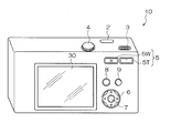
- Imaging device 1 and 2 are a perspective view and a rear view, respectively, showing an embodiment of an imaging apparatus according to the present invention.
- the imaging device 10 is a digital camera that receives light passing through a lens with an imaging device, converts the light into a digital signal, and records it on a recording medium as still image or moving image data.
- the imaging device 10 is provided with a photographing lens 12, a strobe 1 and the like on the front, and a shutter button 2, a power / mode switch 3, a mode dial 4 and the like on the top.
- a liquid crystal monitor 30 for display, a zoom button 5, a cross button 6, a MENU / OK button 7, a playback button 8, a BACK button 9, and the like are disposed on the back of the camera.
- the photographing lens 12 is constituted by a retractable zoom lens, and is set out from the camera body by setting the camera mode to the photographing mode by the power / mode switch 3.
- the strobe 1 irradiates strobe light toward a main subject.
- the shutter button 2 is composed of a two-stroke switch composed of a so-called “half press” and “full press”.
- the AE / AF is activated by pressing the shutter button 2 halfway, and the AE / AF is activated. ”Is executed to execute shooting. Further, when the imaging apparatus 10 is driven in the shooting mode, the shutter button 2 is “fully pressed” to execute shooting.
- the power / mode switch 3 has both a function as a power switch for turning on / off the power of the image pickup apparatus 10 and a function as a mode switch for setting the mode of the image pickup apparatus 10. It is slidably arranged between “position” and “photographing position”. The image pickup apparatus 10 is turned on by sliding the power / mode switch 3 to the “reproduction position” or “photographing position”, and turned off by setting it to the “OFF position”. Then, the power / mode switch 3 is slid and set to “playback position” to set to “playback mode”, and to the “shooting position” to set to “shooting mode”.
- the mode dial 4 functions as a shooting mode setting means for setting the shooting mode of the imaging device 10, and the shooting mode of the imaging device 10 is set to various modes depending on the setting position of the mode dial. For example, there are a “still image shooting mode” for performing still image shooting, a “moving image shooting mode” for moving image shooting, and the like.
- the liquid crystal monitor 30 displays a live view image (through image) in the shooting mode, displays a still image or a moving image in the playback mode, and displays a menu screen, etc., thereby displaying a graphical user interface (GUI). It functions as a part.
- GUI graphical user interface
- the zoom button 5 functions as zoom instruction means for instructing zooming, and includes a tele button 5T for instructing zooming to the telephoto side and a wide button 5W for instructing zooming to the wide angle side.
- the focal length of the photographic lens 12 is changed by operating the tele button 5T and the wide button 5W in the photographing mode. Further, when the tele button 5T and the wide button 5W are operated in the reproduction mode, the image being reproduced is enlarged or reduced.
- the cross button 6 is an operation unit for inputting instructions in four directions, up, down, left, and right, and is a button (cursor moving operation means) for selecting an item from a menu screen or instructing selection of various setting items from each menu.
- the left / right key functions as a frame advance (forward / reverse feed) button in the playback mode.
- the MENU / OK button 7 is an operation having a function as a menu button for instructing to display a menu on the screen of the liquid crystal monitor 30 and a function as an OK button for instructing confirmation and execution of selection contents. Button.
- the playback button 8 is a button for switching to a playback mode in which a captured still image or moving image is displayed on the liquid crystal monitor 30.
- the BACK button 9 functions as a button for instructing to cancel the input operation or return to the previous operation state.
- buttons / switches are not provided with a specific member, but a touch panel is provided to operate the buttons / switches by operating them. Good.
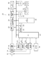
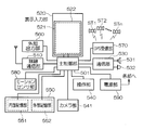
- FIG. 3 is a block diagram showing an embodiment of the internal configuration of the imaging apparatus 10.
- the imaging apparatus 10 records captured images on a memory card 54, and the overall operation of the apparatus is controlled by a central processing unit (CPU) 40.
- CPU central processing unit
- the imaging device 10 has operations such as the shutter button 2, the power / mode switch 3, the mode dial 4, the tele button 5T, the wide button 5W, the cross button 6, the MENU / OK button 7, the playback button 8, the BACK button 9, and the like.
- a portion 38 is provided.
- a signal from the operation unit 38 is input to the CPU 40, and the CPU 40 controls each circuit of the imaging device 10 based on the input signal. For example, image sensor drive control, lens drive control, aperture drive control, photographing operation control, Image processing control, image data recording / reproduction control, display control of the liquid crystal monitor 30, and the like are performed.
- the luminous flux that has passed through the photographing lens 12, the diaphragm 14, the mechanical shutter (mechanical shutter) 15 and the like forms an image on the imaging element 16 that is a CMOS (Complementary Metal-Oxide Semiconductor) type color image sensor.
- the image sensor 16 is not limited to the CMOS type, but may be an XY address type or a CCD (Charge-Coupled Device) type color image sensor.
- the image sensor 16 has a large number of light receiving elements (photodiodes) arranged in a two-dimensional array, and a subject image formed on the light receiving surface of each photodiode is an amount of signal voltage (or charge) corresponding to the amount of incident light. Is converted into a digital signal via an A / D converter in the image sensor 16 and output.
- photodiodes light receiving elements
- a / D converter A / D converter
- the image pickup device 16 has a color filter array exemplified below on a plurality of pixels composed of photoelectric conversion elements (photodiodes) arranged in a horizontal direction (first direction) and a vertical direction (second direction).
- the color filter is arranged.
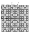
- FIG. 4 is a diagram showing an embodiment of the image sensor 16, and particularly shows a new color filter array arranged on the light receiving surface of the image sensor 16.
- the color filter array of the image sensor 16 shown in FIG. 4 includes a basic array pattern P (pattern indicated by a thick frame) corresponding to M ⁇ N (6 ⁇ 6) pixels, and this basic array pattern P is in the horizontal direction. It is repeatedly arranged in the (left / right direction: first direction) and vertical direction (up / down direction: second direction). That is, in this color filter array, red (R), green (G), and blue (B) color filters (R filter, G filter, and B filter) are arranged with periodicity. Since the R filter, G filter, and B filter are arranged with periodicity in this way, when performing image processing of RGB RAW data (mosaic image) read from the image sensor 16, processing is performed according to a repetitive pattern. It can be carried out.
- RGB RAW data mosaic image
- the basic array pattern of 6 ⁇ 6 pixels is not limited to the basic array pattern P but includes a basic array pattern P ′ cut out from a position different from the basic array pattern P.
- the G filter corresponding to the color that contributes most to obtain the luminance signal is the horizontal, vertical, diagonal upper right, and diagonal upper left of the color filter array.
- One or more pixels are arranged in each pixel line in the direction.
- the pixel line refers to a line in which pixels are arranged in a line in the horizontal, vertical, diagonally upper right, or diagonally upper left direction.
- the diagonal upper right direction and the diagonal lower right direction in this embodiment are directions inclined by 45 ° with respect to the horizontal direction and the vertical direction, respectively. This is because a plurality of pixels and color filters are arranged in a square lattice pattern in the horizontal direction and the vertical direction. Therefore, when a plurality of pixels and color filters are arranged in a rectangular grid, the diagonal directions of the rectangular grid correspond to the diagonally upper right direction and diagonally upper left direction.
- the G filter corresponding to the luminance system pixel is arranged in each pixel line in the horizontal, vertical, diagonal upper right and diagonal upper left directions of the color filter array, it can be synchronized in the high frequency region regardless of the direction of high frequency.
- the reproducibility of processing can be improved.
- the synchronization process is a process for calculating (converting into simultaneous expression) all the RGB color information for each pixel from the RGB mosaic image associated with the color filter array of the single-plate color image sensor. Also called processing or demosaicing processing.
- the color filter array shown in FIG. 4 includes an R filter and a B filter corresponding to two or more other colors (in this embodiment, R and B colors) other than the G color.
- One or more pixels are arranged in each pixel line in the horizontal and vertical directions of P.
- the R filter and the B filter are arranged in each pixel line in the horizontal and vertical directions of the color filter array, generation of false colors (color moire) can be reduced. Thereby, an optical low-pass filter for reducing (suppressing) the occurrence of false colors can be omitted. Even when an optical low-pass filter is applied, a filter having a weak function of cutting high-frequency components for preventing the occurrence of false colors can be applied, and resolution can be maintained.
- the basic arrangement pattern P of the color filter arrangement shown in FIG. 4 has the number of R, G, and B pixels corresponding to the R, G, and B filters in the basic arrangement pattern as 8 pixels and 20 pixels, respectively. , 8 pixels. That is, the ratio of the number of pixels of RGB pixels is 2: 5: 2, and the ratio of the number of G pixels that contributes most to obtain a luminance signal is the ratio of R pixels and B pixels of other colors. It is larger than the ratio of the number of pixels.
- the ratio between the number of G pixels and the number of R and B pixels is different, and in particular, the ratio of the number of G pixels that contributes most to obtain a luminance signal is equal to the number of R and B pixels. Since the ratio is larger than the ratio, aliasing at the time of the synchronization process can be suppressed and high frequency reproducibility can be improved.
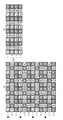
- FIG. 5 shows a state in which the basic array pattern P shown in FIG. 4 is divided into 4 ⁇ 3 ⁇ 3 pixels and a first arrangement example of phase difference pixels to be described later.
- the basic array pattern P includes a 3 ⁇ 3 pixel A array (first sub array) surrounded by a solid line frame and a 3 ⁇ 3 pixel B array (second array) surrounded by a broken line frame. It can also be considered that the sub-arrays are arranged in the horizontal and vertical directions alternately.
- G filters (first colors) are arranged at the four corners and the center, respectively, and arranged on both diagonal lines.
- the R filter first constituent color
- the B filter second constituent color
- the B filter is arranged in the horizontal direction (first direction) with the central G filter interposed therebetween, and the R filter is arranged in the vertical direction. That is, in the A array and the B array, the positional relationship between the R filter and the B filter is reversed, but the other arrangements are the same.
- the G filters at the four corners of the A array and the B array become a square array G filter corresponding to 2 ⁇ 2 pixels by alternately arranging the A array and the B array in the horizontal and vertical directions.
- the pixel at the upper left G filter position among the G filters at the four corners of the A arrangement is configured as the first phase difference pixel p1
- the pixel at the position of the lower left G filter among the G filters at the four corners is configured as the second phase difference pixel p2.
- the first phase difference pixel p1 is present only in the upper A array in the basic array pattern shown in FIG. 5, and the second phase difference pixel p2 is present only in the lower A array in the basic array pattern. Therefore, the phase difference pixels are arranged only in the A array.
- 6 (a) and 6 (b) are enlarged views of the main part showing the configurations of the first phase difference pixel p1 and the second phase difference pixel p2, respectively.
- a light shielding member 16A is disposed on the front side (microlens L side) of the photodiode PD of the first phase difference pixel p1, while FIG. As shown, a light shielding member 16B is disposed on the front side of the photodiode PD of the second phase difference pixel p2.
- the microlens L and the light shielding members 16A and 16B have a function as pupil dividing means, and as shown in FIG. 6A, the light shielding member 16A shields the left half of the light receiving surface of the photodiode PD.
- the first phase difference pixel p1 As shown in FIG. 6B, the light shielding member 16B shields the right half of the light receiving surface of the photodiode PD of the second phase difference pixel p2. Therefore, only the light beam that passes through the right side of the optical axis among the light beams that pass through the exit pupil of the photographing lens 12 is received by the second phase difference pixel p2.
- the light beam passing through the exit pupil is divided into left and right by the microlens L and the light shielding members 16A and 16B, which are pupil dividing means, and are incident on the first phase difference pixel p1 and the second phase difference pixel p2, respectively. To do.
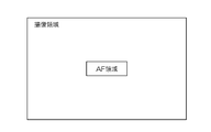
- the first phase difference pixel p1 and the second phase difference pixel p2 are provided in the AF area (focus detection area) at the center in the imaging area of the imaging device 16, as shown in FIG.
- the first phase difference pixel p1 and the second phase difference pixel p2 are preferably arranged from several tens of pixels to about 100 pixels in the phase difference detection direction (horizontal direction in this embodiment), and a pair of them in the vertical direction.
- a plurality of pairs of phase difference pixels are preferably arranged.
- the AF area is not limited to the example shown in FIG. 7, and a plurality of AF areas may be provided in the imaging area as shown in FIGS. 8A to 8C, or may be provided in the entire imaging area. It may be.
- the sensor drive unit 32 is a color image acquisition unit that reads a digital signal (image signal) from the image sensor 16 in response to a read command from the CPU 40, and sequentially reads the image signal for each pixel line from the image sensor 16.
- a thinning readout command such as 1/3 thinning or 1/6 thinning is applied from the CPU 40, an image signal of a pixel line corresponding to a thinning pattern described later is selectively read out.
- the reading method in the CMOS image sensor is a rolling shutter method in which resetting and reading are sequentially performed for each pixel line from above.
- This rolling shutter system has a problem that the image of the subject is distorted in the case of a moving subject because there is a time difference in exposure timing for each pixel line. Therefore, during still image shooting, the shutter drive unit 33 controls the mechanical shutter 15 to open and close (controls the exposure time) so that distortion due to the rolling shutter does not occur.
- the rolling shutter system is a MOS type image pickup device in which an exposure operation is sequentially performed for at least one or more scanning lines or pixels, that is, reset is sequentially performed for each scanning line or pixel to start and accumulate charges. This is a method of reading out charges (also called a focal plane shutter method).
- Image signals (R, G, B signals) read from the image sensor 16 are output to the image input controller 22.
- the digital signal processing unit 24 performs signal processing such as offset processing, white balance correction, gamma correction processing, synchronization processing, YC processing, and moving image generation processing on a digital image signal input via the image input controller 22. Etc.
- the image data processed by the digital signal processing unit 24 is input to the VRAM 50.
- the VRAM 50 includes an A area and a B area for recording image data each representing an image for one frame.
- image data representing an image for one frame is rewritten alternately in the A area and the B area.
- the written image data is read from an area other than the area where the image data is rewritten.
- the image data read from the VRAM 50 is encoded by the video encoder 28 and output to the liquid crystal monitor 30 provided on the back of the camera, whereby the subject image is continuously displayed on the display screen of the liquid crystal monitor 30. .
- the CPU 40 always performs AF operation and AE (automatic exposure) operation during shooting / displaying a through image (live view image) and shooting / recording (recording) a moving image.
- the AF processing unit (phase difference detection means) 42 is a part that performs the phase difference AF processing according to the present invention, and each output signal of the first phase difference pixel p1 and the second phase difference pixel p2 shown in FIG. To detect the phase difference. Details of the phase difference detection by the AF processing unit 42 will be described later.
- the CPU 40 functions as a focus adjustment unit that performs phase difference AF based on the phase difference data. That is, the CPU 40 calculates a deviation amount (defocus amount) between the focus position of the photographing lens 12 and the imaging surface of the image sensor 16 based on the phase difference data, and the lens so that the calculated defocus amount becomes zero.
- the focus lens in the photographic lens 12 is moved via the drive unit 36.
- the calculation of the defocus amount may be performed by the AF processing unit 42.
- the AE detection unit 44 integrates the G signals of the entire screen or integrates the G signals that are weighted differently at the center and the periphery of the screen, and outputs the integrated value to the CPU 40.
- the CPU 40 calculates the brightness (photographing Ev value) of the subject from the integrated value input from the AE detection unit 44.
- the shooting mode is the still image shooting mode
- the CPU 40 performs the above-described AF control again, and if the shutter button 2 is fully pressed,
- the brightness of the subject (shooting Ev value) is calculated, and based on the calculated shooting EV value, the F value of the aperture 14 and the exposure time (shutter speed) by the mechanical shutter 15 are determined according to the program diagram, and still image shooting ( (Exposure control).
- the shooting mode is the moving image shooting mode
- the CPU 40 starts shooting / recording (recording) of the moving image.
- the mechanical shutter 15 is opened, image data is continuously read from the image sensor 16 (for example, frame rates of 30 frames / second, 60 frames / second), and phase difference AF is continuously performed.
- the brightness of the subject is calculated, and the shutter driving unit 33 controls the shutter speed (charge accumulation time by the rolling shutter) and / or the diaphragm 14 by the diaphragm driving unit 34.
- the CPU 40 moves the zoom lens forward and backward in the optical axis direction via the lens driving unit 36 in accordance with the zoom command from the zoom button 5 to change the focal length.
- the ROM 47 is a ROM (EEPROM) in which a camera control program, defect information of the image sensor 16, various parameters and tables used for image processing, a thinning pattern for thinning and reading out moving images, and the like are stored.
- EEPROM EEPROM
- the image data output from the image sensor 16 when shooting a moving image or a still image is input from the image input controller 22 to the memory (SDRAM) 48 and temporarily stored.
- SDRAM memory
- the image data temporarily stored in the memory 48 is appropriately read out by the digital signal processing unit 24.
- gain control processing including offset processing, white balance correction, sensitivity correction, gamma correction processing, and synchronization processing.
- YC processing luminance data and color difference of image data
- Signal processing including data generation processing is performed, and the YC-processed image data (YC data) is stored in the memory 48 again.
- the YC data stored in the memory 48 is output to the compression / decompression processing unit 26, and after being subjected to compression processing such as JPEG (joint photographic photographic experts group), it is stored in the memory 48 again.
- An image file is generated from the YC data (compressed data) stored in the memory 48, and the image file is read by the media controller 52 and recorded on the memory card 54.
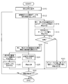
- FIG. 9 is a flowchart showing an image processing method according to the present invention, and particularly shows image processing during moving image shooting.
- the CPU 40 obtains a thinning rate for thinning and reading out image data from the image sensor 16 during moving image shooting (step S10).
- This thinning rate may be a fixed value set in advance, or may be selected by the user from a plurality of thinning rates. For example, an optimum thinning rate can be set in conjunction with the selection of the image size of the moving image or the selection of the frame rate.
- the CPU 40 outputs a reading command indicating a thinning pattern corresponding to the thinning rate to the sensor driving unit 32, and reads out the image data from the image sensor 16 (step S12).
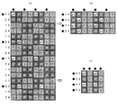
- FIG. 10 is a conceptual diagram showing a first arrangement example of phase difference pixel images in the image sensor 16 and how image data is thinned out and read out from the image sensor 16.
- 10 to 15 shown below are conceptual diagrams showing how thinning-out reading is performed, but black circle marks are applied to pixel lines that perform thinning-out reading in the first direction (horizontal direction) and the second direction (vertical direction). Is shown.
- all the pixel lines of RAW data (mosaic image) having the same color array as the color filter array of the image sensor 16 can be read from the image sensor 16.
- 1/3 (2/6) thinning readout is possible, in which 2 pixel lines of 6 pixel lines are thinned and read out along the second direction (vertical direction). Performs half-thinning readout by thinning out and reading out one pixel line every two pixel lines along the first direction (horizontal direction), and two pixels of the six pixel lines along the second direction (vertical direction). It is also possible to perform 1/3 (2/6) thinning readout for thinning out lines.
- 1/3 (2/6) thinning readout is performed along the second direction (vertical direction) in the high-resolution shooting mode, and the first direction (horizontal direction) in the low-resolution shooting mode and the live view display mode. ) And the second direction (vertical direction).
- the first phase difference pixel p1 is arranged at the position of the G pixel located at the upper left in the A array of the upper 3 ⁇ 3 pixels in the basic array pattern (see FIG. 5). Further, the second phase difference pixel p2 is arranged at the position of the lower left G pixel in the lower 3 ⁇ 3 pixel A array in the basic array pattern (see FIG. 5). In addition, in the basic array patterns adjacent in the vertical direction, the arrangement positions of the first phase difference pixels p1 and the second phase difference pixels p2 are switched.
- a pixel line including the first phase difference pixel p1 and the second phase difference pixel p2 is read out. That is, a thinning pattern indicating which pixel line is read out is set in advance corresponding to the thinning rate, and only image data of the pixel line corresponding to the thinning pattern is read out. Thereby, moving image data can be generated.
- the A array or the B array is 3 ⁇ 3 pixels
- the A array and the B array are alternately repeated for every three pixel lines in the vertical direction
- the basic array pattern is 6 ⁇ 6 pixels
- the same basic arrangement pattern is repeated every six pixel lines in the direction.
- numbers 1 to 3 are assigned to the three pixel lines corresponding to the A array or the B array (left side), and numbers 1 to 6 are assigned to the six pixel lines corresponding to the basic array pattern. Attached (right side). Since the first phase difference pixel p1 is arranged on the pixel line corresponding to number 1 of the upper A array, and the second phase difference pixel p2 is arranged on the pixel line corresponding to number 3 of the lower A array, In the case of 1/3 (2/6) thinning readout, as shown in FIG. 10B, pixel lines corresponding to the numbers 1 and 3 of the A array or the B array (numbers 1 and 6 of the basic array pattern). Image data of a pixel line corresponding to (1) is read out.
- step S12 when image data for one frame is thinned and read out in step S12, AF operation and moving image generation processing are performed in parallel as shown below.
- the AF processing unit 42 extracts the image data (output data) of the first phase difference pixel p1 and the second phase difference pixel p2 in the AF area from the image data for one frame that has been thinned out and read out.
- the phase difference between the output data of the first phase difference pixel p1 and the output data of the second phase difference pixel p2 is detected (step S14). For example, when the correlation between the output data of the pair of upper and lower first phase difference pixels p1 and the second phase difference pixel p2 is maximized (the integrated value of the absolute differences of the output data of the pair of upper and lower phase difference pixels is The phase difference is obtained from the shift amount in the left-right direction between the output data (when it is minimum).
- the CPU 40 calculates a deviation amount (defocus amount) between the focus position of the photographing lens 12 and the imaging surface of the image sensor 16 based on the phase difference data detected in step S14 ( Step S16).
- the calculation of the defocus amount may be performed by the AF processing unit 42.
- the CPU 40 determines whether or not the focus lens in the photographing lens 12 is at the in-focus position from the calculated defocus amount (step S18). If it is determined that the focus position is not reached (in the case of “No”), the focus lens in the photographing lens 12 is moved through the lens driving unit 36 so that the calculated defocus amount becomes zero (step S20). If it is determined that it is in the in-focus position (in the case of “Yes”), the process proceeds to step S32.
- the moving image generation processing is performed in parallel with the processing from step S14 to step S20.
- step S22 the interpolation calculation means in the digital signal processing unit 24 at the pixel positions of the first phase difference pixel p1 and the second phase difference pixel p2.
- the pixel value (image data) of the pixel (G pixel) is calculated.
- the image data of the G pixel at the position is calculated by interpolation of image data of a plurality of surrounding G pixels (in this embodiment, a plurality of G pixels including G pixels adjacent in the left-right direction).
- the calculated image data is G pixel image data at the pixel positions of the first phase difference pixel p1 and the second phase difference pixel p2.
- the digital signal processing unit 24 reads out the R, G, and B image data read out as shown in FIG. 10B (the G pixel at the pixel position of the phase difference pixel is interpolated image data). Based on the above, a moving image generation process is performed on which signal processing such as white balance correction, gamma correction processing, synchronization processing, and YC processing has been performed.
- the data balance may not match in the direction (vertical direction).
- synchronization processing is once performed on the mosaic image that has been thinned and read, and then processing for reducing the data is performed. For example, when 1/4 or 1/3 decimation readout is performed in the second direction (vertical direction) and all pixel readout is performed in the first direction (horizontal direction), the mosaic image obtained by the decimation readout is temporarily displayed. Alternatively, the synchronization process may be performed, and then the pixel data may be reduced in the first direction (horizontal direction).
- the R, G, and B mosaic images after thinning are arranged with a large number of normal G pixels around the phase difference pixels, so that the accuracy of interpolation of the phase difference pixels is increased.
- the R, G, and B pixels are arranged on all the pixel lines in the horizontal direction (first direction), the accuracy of the synchronization process can be increased.
- R pixels and B pixels are alternately arranged on the pixel line in the vertical direction. The accuracy of (demosaic processing) can be increased.
- the digital signal processing unit 24 thins out (extracts) the image of the vertical pixel line after the synchronization processing in the same manner as the thinning (1/3 thinning) reading of the pixel line in the horizontal direction (first direction). Then, an image (reduced image) thinned out in the horizontal direction (first direction) and the vertical direction is generated.
- the moving image generated by the digital signal processing unit 24 is converted into compressed moving image data such as motion JPEG, MPEG (Moving Picture Experts Group) -4 by the compression / decompression processing unit 26, and then stored in the memory via the media controller 52.
- the data is recorded on the card 54 (step S26).
- the digital signal processing unit 24 generates a moving image for display to be displayed on the liquid crystal monitor 30 in parallel with the generation of the moving image for recording (step S28).
- the moving image for display is an image further reduced in accordance with the display size of the liquid crystal monitor 30.
- the generated moving image for display is output to the liquid crystal monitor 30 via the video encoder 28 and displayed as a through image (step S30).
- the user can confirm the image during the moving image shooting with the through image displayed on the liquid crystal monitor 30.
- the CPU 40 determines whether or not there is an instruction input for the end of moving image shooting (pressing the shutter button 2 again) from the operation unit 38 (step S32). If there is an instruction input for ending the video recording (when “Yes”), the video recording / recording is ended, while if no video ending instruction is input (when “No”) In step S12, the moving image recording / recording is continued.
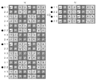
- FIG. 11 is a conceptual diagram showing a second arrangement example of the phase difference pixels in the image sensor 16 and how the image data is thinned and read out from the image sensor 16.
- the color filter array of the image sensor 16 is basically the same as that shown in FIG. 5 in that the A array and the B array of 3 ⁇ 3 pixels are alternately arranged in the horizontal and vertical directions.
- the pixel at the upper left G filter position among the G filters at the four corners of the A arrangement and the B arrangement in the first direction (horizontal direction) includes the first phase difference pixel p1 and Only one of the phase difference pixels of the second phase difference pixels p2 is arranged, while the upper left G of the G filters at the four corners of the A array and the B array in the second direction (vertical direction).
- the pixel at the filter position is different from the basic array pattern shown in FIG. 5 in that the first phase difference pixel p1 and the second phase difference pixel p2 are alternately arranged.
- the color filter array shown in FIG. 11A has four phase difference pixels in the basic array pattern, whereas the color filter array shown in FIG. The point which has two phase difference pixels in the basic array pattern is mentioned.
- the number 1 in the A array or B array of 3 ⁇ 3 pixels is set.
- the image data of the corresponding pixel line (pixel line corresponding to number 1 and number 4 of the basic array pattern) is read out.
- the phase difference pixels are arranged in the same direction in the first direction (horizontal direction), and in the second direction (vertical direction).
- the first phase difference pixel p1 and the second phase difference pixel p2 are alternately arranged.
- the second colors are arranged so as not to be continuous in the second direction (vertical direction) (in the case of FIG. 11B, B and R are alternately arranged).
- the color filter array is not limited to the array shown in FIG. 4 or the like, and may be an array as shown in FIG.
- the color filter array shown in FIG. 12A is common to the color filter array shown in FIG. 4 in that the basic array pattern is repeatedly arranged in the horizontal and vertical directions. However, the color filter array shown in FIG. 12A is different from the color filter array shown in FIG. 4 in that the basic array pattern is 3 ⁇ 6 pixels.
- the same kind of array for example, the A array and the A array
- the horizontal direction first direction
- different kinds of arrays for example, the A direction and the first direction
- the basic array pattern is 3 ⁇ 6 pixels.
- the arrangement of the phase difference pixels p1 and p2 in the color filter array shown in FIG. 12A is different from the arrangement of the phase difference pixels p1 and p2 in the color filter array shown in FIG. That is, in the color filter array shown in FIG. 12A, the pixel corresponding to the position of the G filter located in the upper left of the A array is configured as a phase difference pixel, and in the horizontal direction (first direction) The same type of phase difference pixels are arranged, and different types of phase difference pixels are arranged in the vertical direction.
- the R, G, B mosaic image after thinning-out readout has R, G, B pixels arranged on all pixel lines in the first direction (horizontal direction).
- the accuracy of the synchronization process can be increased.
- the R pixel and the B pixel are alternately arranged on the vertical pixel line, so that the accuracy of the synchronization processing can be increased.
- the color filter array is not limited to the array shown in FIG. 4 or the like, and may be an array as shown in FIG.
- the color filter array shown in FIG. 13A includes a basic array pattern composed of square array patterns corresponding to 4 ⁇ 4 pixels, and this basic array pattern is repeatedly arranged in the horizontal and vertical directions. Although it is common with the color filter array shown in 4 etc., the arrangement of the R, G and B color filters in the basic array pattern is different.
- G filters are arranged in all 2 ⁇ 2 pixels.
- B filters are arranged on the diagonal line that rises to the right of the 2 ⁇ 2 square arrangement, and two R filters are arranged on the diagonal line that rises to the left.
- the first phase difference pixel p1 shown in (a) of FIG. 13 is arranged in the horizontal direction (first order) with reference to the basic arrangement pattern in which the upper left G filter in the upper A arrangement of 2 ⁇ 2 pixels is arranged.
- the second phase difference pixel p2 is arranged at the position of the upper left G filter in the upper A array of 2 ⁇ 2 pixels.
- the second phase difference pixel p1 is based on the basic array pattern arranged at the position of the upper left G filter in the upper A array of 2 ⁇ 2 pixels.
- Phase difference pixel p2 is arranged at the position of the lower left G filter in the upper A array of 2 ⁇ 2 pixels.
- the period in which the phase difference pixel p1 and the phase difference pixel p2 repeat in the horizontal direction (first direction) is two periods of the basic array pattern. Therefore, the cycle of the phase difference pixel p1 and the phase difference pixel p2 is different from the cycle of the basic array pattern.
- the R, G, B mosaic image after thinning-out readout has R, G, B pixels arranged on all the pixel lines in the horizontal direction (first direction).
- the accuracy of the synchronization process can be increased.
- the R pixel and the B pixel are alternately arranged on the pixel line in the vertical direction, so that the accuracy of the synchronization process can be increased.
- the imaging apparatus 10 of the present embodiment it is possible to shorten the processing time per frame by using the thinned color image as a target image for moving image processing, and to reduce the frame rate. Can be prevented from dropping.
- the time for reading an image from the image sensor 16 can be shortened.
- the first and second positions are located on the thinning pattern on the pixel line of the same color on the pixel line in the first direction (horizontal direction). Since the phase difference pixels p1 and p2 are arranged, output signals corresponding to the first and second phase difference pixels can be acquired in two dimensions in the first direction and the second direction (vertical direction). Based on this output signal, the phase difference of each output signal can be detected with high accuracy. As a result, the imaging apparatus 10 can perform the phase difference AF with high accuracy during moving image shooting.
- each of the first filter (G filter of G color) and the second filter (R filter, B filter) corresponding to each color of the second color (R color, B color) has a basic arrangement pattern P, Since one or more pixels are arranged in each pixel line in the first direction and the second direction in P ′, when shooting using all pixels without thinning out (for example, a still image), It is possible to reduce the occurrence of false colors and increase the resolution in a captured image (such as a still image), and to use normal pixels (first and second pixels) as peripheral pixels of the first and second phase difference pixels.
- a pixel value of a color pixel at the position of the first and second phase difference pixels is generated by interpolation of pixel values of peripheral pixels including adjacent pixels It can be obtained with high accuracy. Thereby, in the imaging device 10, it is possible to prevent or reduce deterioration of the image quality of the captured image due to the phase difference pixels p1 and p2.
- FIG. 14 is a conceptual diagram showing another arrangement example of the phase difference pixels in the color filter array shown in FIG. 13 and how the image data is read out from the image sensor 16.
- phase difference pixels p1 and p2 arranged at the lower left of the array are arranged at the lower right of the 2 ⁇ 2 upper A array in FIG.
- the first phase difference pixels p1 and the second phase difference pixels p2 are not arranged in a line in the vertical direction but are arranged at positions shifted alternately.
- 1/4 thinning-out reading is performed along the second direction (vertical direction), and in the low-resolution shooting mode and the live view display mode, the first direction (horizontal direction) and the second direction are read out. Thinning readout may be performed in the direction (vertical direction).
- the R, G, and B mosaic images that have been thinned and read out in this manner have the same color arrangement as the mosaic image shown in FIG. 14B, but the first phase difference pixel p1 and the first mosaic image.
- the two phase difference pixels p2 are arranged in a zigzag pattern (checker flag pattern), and normal G pixels are also arranged in a zigzag pattern.
- the R, G, and B mosaic images after thinning-out readout are the G pixel and the phase difference pixel in the first direction (horizontal direction) and the diagonal direction with the R pixel and the B pixel. Since they are in contact, the synchronization accuracy can be increased.
- the pixels of the second color are the same in the vertical direction as in the mosaic image in which RBs, which are the second color obtained after the thinning readout shown in FIG. 15A, are alternately arranged in the vertical direction.
- RBs which are the second color obtained after the thinning readout shown in FIG. 15A
- the first difference exists in the horizontal direction (first direction) of the phase difference pixel p1.
- 2 and the second color existing in the horizontal direction (first direction) of the phase difference pixel p2 are different on the same vertical pixel line (see the arrow in FIG. 15B), and What is necessary is just to extract the pixel line in which the phase difference pixels p1 and p2 exist.
- Condition (1) is that the contribution rate for obtaining the luminance signal is 50% or more. This contribution rate of 50% is a value determined to distinguish the first color (G color, etc.) from the second color (R, B color, etc.) of the present invention, and is used to obtain luminance data. Are determined to be included in the “first color” in which the contribution ratio is relatively higher than the R color, the B color, and the like.
- the image signal of the G pixel has a higher contribution rate when generating the luminance signal than the image signal of the R pixel and the B pixel. More specifically, the luminance signal (Y signal) of a pixel after the synchronization processing is generally expressed by the following equation based on the synchronized R, G, B image signals (R, G, B signals). Is calculated by
- G color is the color that contributes most to the luminance signal among the three primary colors.
- the contribution ratio of colors other than G can be obtained by experiments and simulations. Therefore, a filter having a color that contributes 50% or more other than the G color can also be used as the first filter of the present invention. Note that the color having a contribution ratio of less than 50% is the second color (R color, B color, etc.) of the present invention, and the filter having this color is the second filter of the present invention.
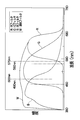
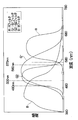
- Condition (2) is that the peak of the transmittance of the filter is in the range of wavelengths from 480 nm to 570 nm.
- a value measured with a spectrophotometer is used as the transmittance of the filter.
- This wavelength range is a range defined for distinguishing between the first color (G color, etc.) and the second color (R, B color, etc.) of the present invention, and the aforementioned contribution ratio is relative. This is a range determined so that peaks such as R color and B color that become lower in general are not included, and peaks such as G color in which the contribution ratio is relatively higher are included.
- a filter having a transmittance peak within a wavelength range of 480 nm to 570 nm can be used as the first filter.
- a filter whose transmittance peak is outside the wavelength range of 480 nm to 570 nm is the second filter (R filter, B filter) of the present invention.
- Condition (3) is that the transmittance within the wavelength range of 500 nm to 560 nm is higher than the transmittance of the second filter (R filter or B filter). Also in this condition (3), the value measured by a spectrophotometer, for example, is used as the transmittance of the filter.
- the wavelength range of the condition (3) is also a range determined to distinguish the first color (G color, etc.) from the second color (R, B color, etc.) of the present invention. This is a range in which the transmittance of a filter having a color whose contribution rate is relatively higher than the color or B color is higher than the transmittance of an RB filter or the like. Therefore, a filter having a relatively high transmittance within a wavelength range of 500 nm to 560 nm can be used as the first filter, and a filter having a relatively low transmittance can be used as the second filter.
- Condition (4) is that a filter of two or more colors including a color that contributes most to the luminance signal (for example, G color of RGB) among the three primary colors and a color different from the three primary colors is used as the first filter. Is to use. In this case, a filter corresponding to a color other than each color of the first filter is the second filter.
- ⁇ Transparent filter (W filter)> a color filter mainly composed of color filters corresponding to RGB colors is shown, but some of these color filters may be transparent filters (W filters corresponding to white pixels).
- W filters corresponding to white pixels it is preferable to arrange the W filter W instead of a part of the first filter (G filter).
- the W filter is a transparent color (first color) filter.
- the W filter can transmit light corresponding to the wavelength range of visible light.
- the W filter has a transmittance of 50% or more for each color of RGB. Since the transmittance of the W filter is higher than that of the G filter, the contribution rate for obtaining the luminance signal is also higher than that of the G color (60%), which satisfies the above condition (1).
- FIG. 16 is a graph showing an example of spectral sensitivity characteristics of each photodiode having an R filter, a G filter, a B filter, and a transparent filter.
- the transmittance peak of the W filter (the peak of the sensitivity of the white pixel) is in the wavelength range of 480 nm to 570 nm. Further, the transmittance of the W filter is higher than the transmittance of the RB filter within a wavelength range of 500 nm to 560 nm. For this reason, the W filter also satisfies the above-described conditions (2) and (3). The G filter satisfies the above conditions (1) to (3) as in the W filter.
- the W filter satisfies the above-mentioned conditions (1) to (3), it can be used as the first filter of the present invention.
- the color filter array a part of the G filter corresponding to the G color that contributes most to the luminance signal among the three primary colors of RGB is replaced with the W filter, so the above condition (4) is also satisfied.
- the G color G filter as the first filter is not limited to one type.
- a plurality of types of G filters may be used as the first filter. That is, the G filter of the color filter (basic array pattern) according to each of the above embodiments may be appropriately replaced with a G1 filter and a G2 filter.
- FIG. 17 is a graph showing an example of spectral sensitivity characteristics of each photodiode having an R filter, a G1 filter, a G2 filter, and a B filter.
- the G1 filter transmits G light in the first wavelength band
- the G2 filter transmits G light in the second wavelength band having a high correlation with the G1 filter.
- an existing G filter for example, the G filter of the first embodiment
- the G2 filter a filter having a high correlation with the G1 filter
- the peak value of the spectral sensitivity curve of the light receiving element in which the G2 filter is disposed is, for example, in a wavelength range of 500 nm to 535 nm (near the peak value of the spectral sensitivity curve of the light receiving element in which the existing G filter is disposed). It is desirable to be.
- a method described in Japanese Patent Application Laid-Open No. 2003-284084 is used as a method for determining the color filters of four colors (R, G1, G2, and B).
- the color of the image acquired by the color imaging device is set to four types, and the color information acquired is increased, so that the color can be more accurately compared with the case where only three types of colors (RGB) are acquired.
- RGB three types of colors
- the transmittance of the G1 and G2 filters is basically the same as the transmittance of the G filter of the first embodiment, so the contribution rate for obtaining the luminance signal is higher than 50%. Therefore, the G1 and G2 filters satisfy the above condition (1).
- the transmittance peak (sensitivity peak of each G pixel) of the G1 and G2 filters is in the wavelength range of 480 nm to 570 nm.
- the transmittances of the G1 and G2 filters are higher than the transmittance of the RB filter within a wavelength range of 500 nm to 560 nm. For this reason, the G1 and G2 filters also satisfy the above conditions (2) and (3).
- E filter a color filter mainly composed of color filters corresponding to RGB colors.
- a part of these color filters may be other color filters, for example, corresponding to emerald (E) colors. It is good also as a filter (E filter corresponding to E pixel).
- FIG. 18 is a graph showing an example of spectral sensitivity characteristics of each photodiode having an R filter, a G filter, a B filter, and an E filter.
- the peak of the transmittance of the E filter (the peak of the sensitivity of the E pixel) is in the wavelength range of 480 nm to 570 nm. Further, the transmittance of the E filter is higher than the transmittance of the RB filter within a wavelength range of 500 nm to 560 nm. For this reason, the E filter satisfies the above-mentioned conditions (2) and (3). Further, in the color filter array, a part of the G filter corresponding to the G color that contributes most to the luminance signal among the three primary colors of RGB is replaced with the E filter, so the above condition (4) is also satisfied.
- the E filter has a peak on the shorter wavelength side than the G filter, but may have a peak on the longer wavelength side than the G filter (it looks a little yellowish).
- an E filter that satisfies the conditions of the present invention can be selected.
- an emerald filter E that satisfies the condition (1) can be selected.
- the color filter array including the primary color RGB color filters has been described.
- G is added to C (cyan), M (magenta), and Y (yellow) which are complementary colors of the primary colors RGB.
- the present invention can also be applied to a color filter array of four complementary color filters.
- the color filter satisfying any one of the above conditions (1) to (4) is set as the first filter of the present invention, and the other color filter is set as the second filter.
- a mobile phone or a smartphone having a camera function for example, a PDA (Personal Digital Assistant), or a portable game machine can be cited.
- a smartphone will be described as an example, and will be described in detail with reference to the drawings.
- FIG. 19 shows the appearance of a smartphone 500 that is another embodiment of the imaging apparatus 10.
- a smartphone 500 illustrated in FIG. 19 includes a flat housing 502, and a display input in which a display panel 521 as a display unit and an operation panel 522 as an input unit are integrated on one surface of the housing 502. Part 520.
- the housing 502 includes a speaker 531, a microphone 532, an operation unit 540, and a camera unit 541.
- the configuration of the housing 502 is not limited thereto, and for example, a configuration in which the display unit and the input unit are independent can be employed, or a configuration having a folding structure and a slide mechanism can be employed.
- FIG. 20 is a block diagram showing a configuration of the smartphone 500 shown in FIG.
- the main components of the smartphone include a wireless communication unit 510, a display input unit 520, a call unit 530, an operation unit 540, a camera unit 541, a storage unit 550, and an external input / output unit. 560, a GPS (Global Positioning System) receiving unit 570, a motion sensor unit 580, a power supply unit 590, and a main control unit 501.
- a wireless communication function for performing mobile wireless communication via the base station device BS and the mobile communication network NW is provided as a main function of the smartphone 500.
- the wireless communication unit 510 performs wireless communication with the base station apparatus BS accommodated in the mobile communication network NW according to an instruction from the main control unit 501. Using this wireless communication, transmission and reception of various file data such as audio data and image data, e-mail data, and reception of Web data and streaming data are performed.
- the display input unit 520 displays images (still images and moving images), character information, and the like visually under the control of the main control unit 501, and visually transmits information to the user, and detects user operations on the displayed information.
- This is a so-called touch panel, and includes a display panel 521 and an operation panel 522.
- the display panel 521 is preferably a 3D display panel. *
- the display panel 521 uses an LCD (Liquid Crystal Display), an OELD (Organic Electro-Luminescence Display), or the like as a display device.
- the operation panel 522 is a device that is placed so that an image displayed on the display surface of the display panel 521 is visible and detects one or more coordinates operated by a user's finger or stylus. When this device is operated by a user's finger or stylus, a detection signal generated due to the operation is output to the main control unit 501. Next, the main control unit 501 detects an operation position (coordinates) on the display panel 521 based on the received detection signal.
- the display panel 521 and the operation panel 522 of the smartphone 500 integrally form the display input unit 520, but the operation panel 522 is disposed so as to completely cover the display panel 521. ing.
- the operation panel 522 may have a function of detecting a user operation even in an area outside the display panel 521.
- the operation panel 522 includes a detection area (hereinafter referred to as a display area) for an overlapping portion that overlaps the display panel 521 and a detection area (hereinafter, a non-display area) for an outer edge portion that does not overlap the other display panel 521. May be included).
- the operation panel 522 may include two sensitive regions of the outer edge portion and the other inner portion. Further, the width of the outer edge portion is appropriately designed according to the size of the housing 502 and the like.
- examples of the position detection method employed in the operation panel 522 include a matrix switch method, a resistance film method, a surface acoustic wave method, an infrared method, an electromagnetic induction method, and a capacitance method. You can also
- the call unit 530 includes a speaker 531 and a microphone 532, and converts a user's voice input through the microphone 532 into voice data that can be processed by the main control unit 501, and outputs the voice data to the main control unit 501, or a wireless communication unit 510 or the audio data received by the external input / output unit 560 is decoded and output from the speaker 531.
- the speaker 531 can be mounted on the same surface as the display input unit 520 and the microphone 532 can be mounted on the side surface of the housing 502.
- the operation unit 540 is a hardware key using a key switch or the like, and receives an instruction from the user.
- the operation unit 540 is mounted on the lower and lower side of the display unit of the housing 502 of the smartphone 500 and turns on when pressed with a finger or the like, and restores a spring or the like when the finger is released. It is a push button type switch that is turned off by force.
- the storage unit 550 includes control programs and control data of the main control unit 501, address data in which names and telephone numbers of communication partners are associated, transmitted and received e-mail data, Web data downloaded by Web browsing, and downloaded contents Data is stored, and streaming data and the like are temporarily stored.
- the storage unit 550 includes an internal storage unit 551 with a built-in smartphone and an external storage unit 552 having a removable external memory slot.
- Each of the internal storage unit 551 and the external storage unit 552 constituting the storage unit 550 includes a flash memory type (flash memory type), a hard disk type (hard disk type), a multimedia card micro type (multimedia card micro type), It is realized using a storage medium such as a card type memory (for example, Micro SD (registered trademark) memory), RAM (Random Access Memory), ROM (Read Only Memory), or the like.
- flash memory type flash memory type
- hard disk type hard disk type
- multimedia card micro type multimedia card micro type
- a storage medium such as a card type memory (for example, Micro SD (registered trademark) memory), RAM (Random Access Memory), ROM (Read Only Memory), or the like.
- the external input / output unit 560 serves as an interface with all external devices connected to the smartphone 500, and communicates with other external devices (for example, universal serial bus (USB), IEEE1394, etc.) or a network.
- external devices for example, universal serial bus (USB), IEEE1394, etc.
- a network for example, Internet, wireless LAN, Bluetooth (registered trademark), RFID (Radio Frequency Identification), Infrared Data Association (IrDA) (registered trademark), UWB (Ultra Wide Band) (registered trademark), ZigBee ( ZigBee) (registered trademark, etc.) for direct or indirect connection.
- Examples of the external device connected to the smartphone 500 include a memory card connected via a wired / wireless headset, wired / wireless external charger, wired / wireless data port, card socket, and SIM (Subscriber).
- Identity Module Card / UIM User Identity Module Card
- external audio / video equipment connected via audio / video I / O (Input / Output) terminal
- external audio / video equipment connected wirelessly, yes / no
- the external input / output unit may transmit data received from such an external device to each component inside the smartphone 500, or may allow data inside the smartphone 500 to be transmitted to the external device. it can.
- the GPS receiving unit 570 receives GPS signals transmitted from the GPS satellites ST1 to STn in accordance with instructions from the main control unit 501, performs positioning calculation processing based on the received GPS signals, and calculates the latitude of the smartphone 500 Detect the position consisting of longitude and altitude.
- the GPS reception unit 570 can acquire position information from the wireless communication unit 510 or the external input / output unit 560 (for example, a wireless LAN), the GPS reception unit 570 can also detect the position using the position information.
- the motion sensor unit 580 includes a triaxial acceleration sensor, for example, and detects the physical movement of the smartphone 500 in accordance with an instruction from the main control unit 501. By detecting the physical movement of the smartphone 500, the moving direction and acceleration of the smartphone 500 are detected. This detection result is output to the main control unit 501.
- the power supply unit 590 supplies power stored in a battery (not shown) to each unit of the smartphone 500 in accordance with an instruction from the main control unit 501.
- the main control unit 501 includes a microprocessor, operates according to a control program and control data stored in the storage unit 550, and controls each unit of the smartphone 500 in an integrated manner. Further, the main control unit 501 includes a mobile communication control function for controlling each unit of the communication system and an application processing function in order to perform voice communication and data communication through the wireless communication unit 510.
- the application processing function is realized by the main control unit 501 operating according to the application software stored in the storage unit 550.
- the application processing function includes, for example, an infrared communication function for controlling the external input / output unit 560 to perform data communication with the opposite device, an e-mail function for sending / receiving e-mails, a web browsing function for browsing web pages, and the present invention. And a function for generating a 3D image from the 2D image according to the above.
- the main control unit 501 has an image processing function such as displaying video on the display input unit 520 based on image data (still image data or moving image data) such as received data or downloaded streaming data.
- the image processing function is a function in which the main control unit 501 decodes the image data, performs image processing on the decoding result, and displays an image on the display input unit 520.
- the main control unit 501 executes display control for the display panel 521 and operation detection control for detecting a user operation through the operation unit 540 and the operation panel 522.
- the main control unit 501 displays an icon for starting application software, a software key such as a scroll bar, or a window for creating an e-mail.
- a software key such as a scroll bar, or a window for creating an e-mail.
- the scroll bar refers to a software key for accepting an instruction to move the display portion of a large image that does not fit in the display area of the display panel 521.
- the main control unit 501 detects a user operation through the operation unit 540, or accepts an operation on the icon or an input of a character string in the input field of the window through the operation panel 522. Or a display image scroll request through a scroll bar.
- the main control unit 501 causes the operation position with respect to the operation panel 522 to overlap with the display panel 521 (display area) or other outer edge part (non-display area) that does not overlap with the display panel 521.
- a touch panel control function for controlling the sensitive area of the operation panel 522 and the display position of the software key.
- the main control unit 501 can also detect a gesture operation on the operation panel 522 and execute a preset function according to the detected gesture operation.
- Gesture operation is not a conventional simple touch operation, but an operation that draws a trajectory with a finger or the like, designates a plurality of positions at the same time, or combines these to draw a trajectory for at least one of a plurality of positions. means.
- the camera unit 541 is a digital camera that performs electronic photography using the imaging device 16 such as a CMOS (Complementary Metal Oxide Semiconductor) or a CCD (Charge-Coupled Device), and has a function equivalent to the function shown in the block diagram of FIG. I have.
- the color filter array of the image sensor, the array of phase difference pixels, and the like in the camera unit 541 can use the same mode as that of the image capturing apparatus 10, and image processing / control processing ( Thinning readout, phase difference detection, focus adjustment, and the like) can be performed in the same manner as described above for the imaging apparatus 10.
- the camera unit 541 converts image data obtained by imaging into compressed image data such as JPEG (Joint Photographic coding Experts Group) under the control of the main control unit 501, and records the data in the storage unit 550 or externally
- the data can be output through the input / output unit 560 and the wireless communication unit 510.
- the camera unit 541 is mounted on the same surface as the display input unit 520, but the mounting position of the camera unit 541 is not limited to this and may be mounted on the back surface of the display input unit 520.
- a plurality of camera units 541 may be mounted. When a plurality of camera units 541 are installed, the camera unit 541 used for shooting may be switched to shoot alone, or a plurality of camera units 541 may be used for shooting simultaneously. it can.
- the camera unit 541 can be used for various functions of the smartphone 500.
- an image acquired by the camera unit 541 can be displayed on the display panel 521, or the image of the camera unit 541 can be used as one of operation inputs of the operation panel 522.
- the GPS receiving unit 570 detects the position, the position can also be detected with reference to an image from the camera unit 541.
- the optical axis direction of the camera unit 541 of the smartphone 500 is determined without using the triaxial acceleration sensor or in combination with the triaxial acceleration sensor. It is also possible to determine the current usage environment.
- the image from the camera unit 541 can be used in the application software.
- the phase difference AF can be accurately performed during moving image shooting as in the case of the imaging device 10, and the deterioration of the image quality of the captured image due to the phase difference pixels can be prevented or reduced. be able to.
- pixel signals are directly thinned and read out from the image sensor 16 according to a thinning pattern during moving image shooting.
- the present invention is not limited to this, and images of all pixels are read out from the image sensor 16.
- a pixel signal may be extracted in accordance with a thinning pattern to obtain a color image having a predetermined color array including phase difference pixels. Even in this case, since the image size of the target image for signal processing including synchronization processing can be reduced, the processing time of the moving image can be shortened.
- the pixel signal according to the thinning pattern may be extracted by a pixel mixing process in which output signals of a plurality of peripheral same-color pixels are added or mixed. .
- the color filter array of the image sensor 16 applied to the present invention is not limited to that shown in FIG. 4, for example, an A array or a B array of 3 ⁇ 3 pixels in the basic array pattern shown in FIG. 4. Only a color filter array in which only a basic filter pattern of M ⁇ N pixels (M, N: an integer of 3 or more) is repeatedly arranged may be used.
- the first color and the second color (in this embodiment, R filter, B filter) corresponding to the first color (in this embodiment, G filter, W filter, G1 filter, G2 filter, E filter) ) May be arranged one or more in each pixel line in the first direction and the second direction (vertical direction) in the basic array pattern.
- the basic array pattern size (M ⁇ N pixels) may be arranged in an array pattern corresponding to the number of other pixels.
- the size of the basic array pattern is preferably not more than 10 ⁇ 10 pixels, and the minimum basic array pattern is preferably 3 ⁇ 3 pixels.
- the filter corresponding to the second color may include a filter of a color other than the R filter and the B filter.
- a color filter array in which C (cyan), M (magenta), and Y (yellow) complementary color filters which are complementary colors of the primary colors RGB, and other color filters are added to the complementary color filter.
- C cyan
- M magenta
- Y yellow
- the present invention can also be applied to an image pickup device having the same.
- the arrangement position of the phase difference pixel is not limited to this embodiment, and it may be arranged on the pixel line that is thinned and read out during moving image shooting.
- the image pickup element applied to the present invention is not limited to one in which a plurality of pixels and color filters are arranged in a square lattice pattern in the horizontal direction (first direction) and the vertical direction as shown in FIG.
- it may be one arranged in an oblique grid (specifically, the color filter array shown in FIG. 4 or the like rotated by 45 °).
- the basic array pattern is also an oblique lattice pattern.
- SYMBOLS 10 Imaging device, 12 ... Shooting lens, 14 ... Aperture, 15 ... Mechanical shutter, 16 ... Imaging element, 24 ... Digital signal processing part, 30 ... Liquid crystal monitor, 32 ... Sensor drive part, 33 ... Shutter drive part, 34 ... Diaphragm Drive unit 36 ... Lens drive unit 40 ... Central processing unit (CPU) 42 ... AF processing unit 47 ... ROM (EEPROM) 48 ... Memory 500 ... Smartphone
Landscapes
- Engineering & Computer Science (AREA)
- Multimedia (AREA)
- Signal Processing (AREA)
- Physics & Mathematics (AREA)
- Spectroscopy & Molecular Physics (AREA)
- Human Computer Interaction (AREA)
- Color Television Image Signal Generators (AREA)
- Studio Devices (AREA)
- Focusing (AREA)
- Automatic Focus Adjustment (AREA)
Description
本発明は撮像装置及び画像処理方法に係り、特に動画の生成と位相差に基づく焦点調節とを並行して行う撮像装置及び画像処理方法に関する。
従来、撮像素子の一部に、撮影レンズの左右の領域を通過した被写体像が瞳分割されてそれぞれ結像される第1、第2の位相差画素を設け、第1、第2の位相差画素の出力信号の位相差を検出し、検出した位相差に基づいてフォーカスレンズの焦点位置を調節する自動焦点調節(位相差AF)が知られている。
特許文献1に記載の撮像素子は、一般的なベイヤ配列のカラーフィルタを有し、水平方向及び垂直方向において、第1の焦点検出用画素(瞳分割左側の画素)と第2の焦点検出用画素(瞳分割右側の画素)とが、一定の周期(水平方向に6画素の周期、垂直方向に3画素の周期)で交互に配置されている。また、第1、第2の焦点検出用画素は、緑(G)フィルタがある画素位置に配置されている。
そして、特許文献1に記載の電子カメラは、焦点検出を行う場合には第1、第2の焦点検出用画素が配置された行の画像(ライン画像)を間引き読み出しし、間引き読出ししたライン画像中の第1、第2の焦点検出用画素の画像信号に基づいて焦点位置を検出してフォーカスレンズの位置を制御するとともに、間引き読出ししたライン画像(第1、第2の焦点検出用画素を含む)の画像信号に基づいてリアルタイムにライブビュー表示を行うようにしている。また、焦点検出を行わない場合には、第1、第2の焦点検出用画素が配置されていないライン画像を読み出し、そのライン画像の画像信号によりライブビュー表示を行うようにしている。
尚、特許文献1に記載の電子カメラは、焦点検出を行う場合には、間引き読出ししたライン画像のうち、第1または第2の焦点検出用画素(G画素)と、このG画素と隣接する赤画素(R画素)または青画素(B画素)とをペアにして抽出し、これらの抽出した画素の画像信号によりライブビュー表示を行うようにしている。したがって、焦点検出を行った時のライブビュー表示には、通常のG画素(第1または第2の焦点検出用画素以外のG画素)の画像信号は使用されていない。
また、特許文献2に記載のカラーフィルタのレイアウトは、前述のベイヤ配列のカラーフィルタの代替えとして提案されている。
特許文献1に記載の発明は、焦点検出を行うとともに、ライブビュー表示を行う場合には、間引き読出しした第1または第2の焦点検出用画素をG画素として使用しているが、焦点検出用画素は、通常の画素とは構造が異なるため、焦点検出用画素をそのままG画素として使用するのは適切でない。
また、特許文献1に記載の撮像素子のカラーフィルタの配列はベイヤ配列であるため、間引き後の画像もベイヤ配列になる。したがって、仮に焦点検出用画素の画像信号を周囲の同じ色の画素の画像信号を補間して求める場合であっても、上下左右に隣接する画素に同色の画素が存在しないため、補間による偽色等が発生しやすいという問題がある。
また、特許文献2に記載の技術は、提案されているカラーフィルタのレイアウトに関して、間引き読み出しの仕方や焦点検出画素の配置の仕方に関して開示が無く、最適な方法が不明であるという問題がある。
本発明はこのような事情に鑑みてなされたもので、ライブビュー表示を含め動画の撮影中に精度よく位相差AFを行うことができ、かつ位相差画素による撮影画像の画質の低下を防止し、または軽減することができる撮像装置及び画像処理方法を提供することを目的とする。
上記目的を達成するために本発明の一の態様に係る撮像装置は、撮影レンズと、第1の方向及び第1の方向に垂直な第2の方向に配列された光電変換素子で構成される複数の画素上に、所定のカラーフィルタ配列のカラーフィルタが配設されてなる撮像素子であって、撮影レンズの異なる第1、第2の領域を通過した被写体像が瞳分割されてそれぞれ結像される第1、第2の位相差画素を含む撮像素子と、撮像素子から、間引きパターンにしたがって複数の画素から画素信号を間引き読み出しし、または撮像素子から読み出した所定のカラーフィルタ配列に対応するカラー画像から間引きパターンにしたがって画素信号を抽出して、間引かれたカラー画像を取得するカラー画像取得手段と、間引かれたカラー画像に基づいて動画データを生成する動画生成手段と、間引かれたカラー画像中に含まれる第1、第2の位相差画素に対応する各出力信号に基づいて各出力信号の位相差を検出する位相差検出手段と、位相差検出手段により検出された位相差に基づいて撮影レンズの焦点位置を調節する焦点調節手段と、を備え、所定のカラーフィルタ配列は、1色以上の第1の色に対応する第1のフィルタと、輝度信号を得るための寄与率が第1の色よりも低い2色以上の第2の色に対応する第2のフィルタとを有し、第1のフィルタと第2のフィルタとが配列された基本配列パターンを含み、基本配列パターンが第1の方向及び第2の方向に繰り返されて配置され、第1のフィルタ及び第2の色の各色に対応する第2のフィルタのそれぞれは、基本配列パターン内の第1の方向及び第2の方向の各ライン内にそれぞれ1以上配置され、間引かれたカラー画像における第2の色は、同一の第2の色が連続しないように第2の方向に延びる1ライン上に配列され、第1、第2の位相差画素は、撮像素子の焦点検出領域内の間引きパターン上であって、第1の方向の画素ライン上の同一の色のフィルタの位置に配置される。
本発明の一の態様によれば、撮像素子から所定の間引きパターンにしたがって第1の方向のライン画像を間引き読み出しし、または撮像素子から読み出したカラーフィルタ配列に対応するカラー画像から間引きパターンにしたがって複数の画素から画素信号を抽出して、間引かれたカラー画像を取得する。そして、間引かれたカラー画像に基づいて動画データを生成するが、間引かれたカラー画像を動画処理の対象画像とすることにより、1フレーム当りの処理時間の短縮化を図ることができ、フレームレートが低下しないようにすることができる。また、撮像素子からライン画像を間引き読出しすることにより、撮像素子からの画像の読出し時間の短縮化を図ることができる。
また、取得したカラー画像の少なくとも焦点検出領域内には、間引きパターンのライン上で、かつ同一の色のフィルタの位置に、第1、第2の位相差画素が配置されているため、第1、第2の位相差画素を第1の方向及び第2の方向の2次元で取得することができ、第1、第2の位相差画素に対応する各出力信号に基づいて精度よく各出力信号の位相差を検出することができる。
更に、第1のフィルタ及び第2の色の各色に対応する第2のフィルタは、基本配列パターン内の第1の方向及び第2の方向の各ライン内にそれぞれ1以上配置されているため、間引かずに全画素を用いた撮影(静止画など)をする場合には、その撮影画像(静止画など)での偽色の発生の低減及び高解像度化を図ることができ、また、第1、第2の位相差画素の周辺画素として通常の画素(第1、第2の位相差画素以外の画素)を配置することができ、第1、第2の位相差画素の位置のカラー画素の画素値を、隣接する画素を含む周辺画素の画素値の補間により生成する際に精度よく求めることができる。
また更に、カラー画像における第2の色は、同一の第2の色が連続しないように第2の方向に延びる1ライン上に配列されているために、同時化処理時に画素値を周辺画素の画素値により精度よく求めることができる。
上記構成により本態様の撮像装置では、動画の撮影中に精度よく位相差AFを行うことができ、かつ、位相差画素による撮影画像の画質の低下を防止し、又は軽減することができる。
本発明の他の態様に係る撮像装置は、撮影レンズと、第1の方向及び第1の方向に垂直な第2の方向に配列された光電変換素子で構成される複数の画素上に、所定のカラーフィルタ配列のカラーフィルタが配設されてなる撮像素子であって、撮影レンズの異なる第1、第2の領域を通過した被写体像が瞳分割されてそれぞれ結像される第1、第2の位相差画素を含む撮像素子と、撮像素子から、間引きパターンにしたがって複数の画素から画素信号を間引き読み出しし、または撮像素子から読み出した所定のカラーフィルタ配列に対応するカラー画像から間引きパターンにしたがって画素信号を抽出して、間引かれたカラー画像を取得するカラー画像取得手段と、間引かれたカラー画像に基づいて動画データを生成する動画生成手段と、間引かれたカラー画像中に含まれる第1、第2の位相差画素に対応する各出力信号に基づいて各出力信号の位相差を検出する位相差検出手段と、位相差検出手段により検出された位相差に基づいて撮影レンズの焦点位置を調節する焦点調節手段と、を備え、所定のカラーフィルタ配列は、透過率のピークが波長480nm以上570nm以下の範囲内にある1色以上の第1の色に対応する第1のフィルタと、透過率のピークが範囲外にある2色以上の第2の色に対応する第2のフィルタとを有し、第1のフィルタと第2のフィルタとが配列された基本配列パターンを含み、基本配列パターンが第1の方向及び第2の方向に繰り返されて配置され、第1のフィルタ及び第2の色の各色に対応する第2のフィルタのそれぞれは、基本配列パターン内の第1の方向及び第2の方向の各ライン内にそれぞれ1以上配置され、間引かれたカラー画像における第2の色は、同一の第2の色が連続しないように第2の方向に延びる1ライン上に配列され、第1、第2の位相差画素は、撮像素子の焦点検出領域内の間引きパターン上であって、第1の方向の画素ライン上の同一の色のフィルタの位置に配置される。本態様の撮像装置においても上記態様と同様に、動画の撮影中に精度よく位相差AFを行うことができ、かつ位相差画素による撮影画像の画質の低下を防止し、又は軽減することができる。
本発明の他の態様は、各フィルタの透過率のピークが波長480nm以上570nm以下の範囲か否かにより第1の色に対応する第1のフィルタと第2の色に対応する第2のフィルタとを区別している点で、前述の本発明の態様と相違する。
本発明の更に他の態様に係る撮像装置は、撮影レンズと、第1の方向及び第1の方向に垂直な第2の方向に配列された光電変換素子で構成される複数の画素上に、所定のカラーフィルタ配列のカラーフィルタが配設されてなる撮像素子であって、撮影レンズの異なる第1、第2の領域を通過した被写体像が瞳分割されてそれぞれ結像される第1、第2の位相差画素を含む撮像素子と、撮像素子から、間引きパターンにしたがって複数の画素から画素信号を間引き読み出しし、または撮像素子から読み出した所定のカラーフィルタ配列に対応するカラー画像から間引きパターンにしたがって画素信号を抽出して、間引かれたカラー画像を取得するカラー画像取得手段と、間引かれたカラー画像に基づいて動画データを生成する動画生成手段と、間引かれたカラー画像中に含まれる第1、第2の位相差画素に対応する各出力信号に基づいて各出力信号の位相差を検出する位相差検出手段と、位相差検出手段により検出された位相差に基づいて撮影レンズの焦点位置を調節する焦点調節手段と、を備え、所定のカラーフィルタ配列は、1色以上の第1の色に対応する第1のフィルタと、波長500nm以上560nm以下の範囲内で透過率が第1のフィルタよりも低くなる2色以上の第2の色に対応する第2のフィルタとを有し、第1のフィルタと第2のフィルタとが配列された基本配列パターンを含み、基本配列パターンが第1の方向及び第2の方向に繰り返されて配置され、第1のフィルタ及び第2の色の各色に対応する第2のフィルタのそれぞれは、基本配列パターン内の第1の方向及び第2の方向の各ライン内にそれぞれ1以上配置され、間引かれたカラー画像における第2の色は、同一の第2の色が連続しないように第2の方向に延びる1ライン上に配列され、第1、第2の位相差画素は、撮像素子の焦点検出領域内の間引きパターン上であって、第1の方向の画素ライン上の同一の色のフィルタの位置に配置される。
本態様の撮像装置においても上記態様と同様に、動画の撮影中に精度よく位相差AFを行うことができ、かつ位相差画素による撮影画像の画質の低下を防止し、又は軽減することができる。
本発明の更に他の態様は、波長500nm以上560nm以下の範囲内の各フィルタの透過率の高低により第1の色に対応する第1のフィルタと第2の色に対応する第2のフィルタとを区別している点で、前述の本発明の態様と相違する。
本発明の他の態様に係る撮像装置は、撮影レンズと、第1の方向及び第1の方向に垂直な第2の方向に配列された光電変換素子で構成される複数の画素上に、所定のカラーフィルタ配列のカラーフィルタが配設されてなる撮像素子であって、撮影レンズの異なる第1、第2の領域を通過した被写体像が瞳分割されてそれぞれ結像される第1、第2の位相差画素を含む撮像素子と、撮像素子から、間引きパターンにしたがって複数の画素から画素信号を間引き読み出しし、または撮像素子から読み出した所定のカラーフィルタ配列に対応するカラー画像から間引きパターンにしたがって画素信号を抽出して、間引かれたカラー画像を取得するカラー画像取得手段と、間引かれたカラー画像に基づいて動画データを生成する動画生成手段と、間引かれたカラー画像中に含まれる第1、第2の位相差画素に対応する各出力信号に基づいて各出力信号の位相差を検出する位相差検出手段と、位相差検出手段により検出された位相差に基づいて撮影レンズの焦点位置を調節する焦点調節手段と、を備え、所定のカラーフィルタ配列は、3原色のうち最も輝度信号に寄与する色と3原色とは異なる色の第4色とを含む2色以上の第1の色に対応する第1のフィルタと、第1の色以外の2色以上の第2の色に対応する第2のフィルタとを有し、第1のフィルタと第2のフィルタとが配列された基本配列パターンを含み、基本配列パターンが第1の方向及び第2の方向に繰り返されて配置され、第1のフィルタ及び第2の色の各色に対応する第2のフィルタのそれぞれは、基本配列パターン内の第1の方向及び第2の方向の各ライン内にそれぞれ1以上配置され、間引かれたカラー画像における第2の色は、同一の第2の色が連続しないように第2の方向に延びる1ライン上に配列され、第1、第2の位相差画素は、撮像素子の焦点検出領域内の間引きパターン上であって、第1の方向の画素ライン上の同一の色のフィルタの位置に配置される。
本態様の撮像装置においても上記態様と同様に、動画の撮影中に精度よく位相差AFを行うことができ、かつ位相差画素による撮影画像の画質の低下を防止し、又は軽減することができる。
本発明の更に他の態様は、3原色のうち最も輝度信号に寄与する色と3原色とは異なる色の第4色とを含む2色以上の第1の色に対応する第1のフィルタと、第1の色以外の2色以上の第2の色に対応する第2のフィルタとで、第1のフィルタと第2のフィルタとを区別している点で、前述の本発明の態様と相違する。
本発明の他の態様に係る撮像装置において、間引かれたカラー画像は、第1、第2の位相差画素に隣接して第1、第2の位相差画素の位置における画素の色と同じ色の画素が配置され、間引かれたカラー画像中の第1、第2の位相差画素の位置における画素の画素値を、第1、第2の位相差画素に隣接する同じ色の画素を含む周辺画素の画素値を補間して算出する補間演算手段を備え、動画生成手段は、間引かれたカラー画像中の第1、第2の位相差画素の位置における画素の画素値として補間演算手段により算出された値を使用したカラー画像に基づいて動画データ生成することが好ましい。間引かれたカラー画像は、第1、第2の位相差画素に隣接して第1、第2の位相差画素の位置における画素の色と同じ色の画素が配置されるため、第1、第2の位相差画素の位置における画素の画素値を周辺画素の同色の画素の画素値を使用して補間演算する際に、周辺画素として第1、第2の位相差画素に隣接する画素を使用することができ、第1、第2の位相差画素の位置における画素の画素値を精度よく算出することができる。
本発明の更に他の態様に係る撮像装置において、間引かれたカラー画像は、第1の色の画素が第2の方向に配列され、かつ第2の色の各色の画素がそれぞれ第2の方向に配列されて構成されることが好ましい。これにより、間引き後のカラー画像の第1の色の画素の第2の方向の解像度を高くすることができる。
本発明の他の態様に係る撮像装置において、第1のフィルタに対応する第1の色の全画素数の比率は、第2のフィルタに対応する第2の色の各色の画素数の比率よりも大きく、第1、第2の位相差画素は、第1のフィルタの位置に配置されることが好ましい。
第1、第2の位相差画素を画素数の多い色のフィルタ(第1のフィルタ)に配置することにより、第1、第2の位相差画素の位置における画素の画素値を、周辺の第1のフィルタの画素の画素値に基づいて精度よく算出することができる。
本発明の他の態様に係る撮像装置において、第1のフィルタは、M×N画素(M、N:3以上の整数)内に複数配置され、M×N画素が第1、第2の方向に繰り返し配置されることが好ましい。
本発明の他の態様に係る撮像装置において、第1、第2の位相差画素のうちの一方の位相差画素が、M×N画素内に1または2つ配置されることが好ましい。これにより、位相差画素を分散して配置することができる。
本発明の他の態様に係る撮像装置において、第1、第2の位相差画素は、第2の方向に第1、第2の位相差画素が一対となって配置されることが好ましい。これにより、第2の方向の最小ピッチで、第1、第2の位相差画素の各出力信号の位相差を検出することができる。
本発明の他の態様に係る撮像装置において、第1、第2の位相差画素は、第1の方向の1ライン上に交互に配置されることが好ましい。
本発明の他の態様に係る撮像装置において、第1の色は、緑(G)色であり、第2の色は、赤(R)色及び青(B)色であり、カラーフィルタは、R、G、Bの色に対応するRフィルタ、Gフィルタ及びBフィルタを有し、カラーフィルタ配列は、2×2画素に対応する第1の配列であって、Gフィルタが4配置された第1の配列と、2×2画素に対応する第2の配列であって、第2の配列の一方の対角線上にBフィルタが配置され、他方の対角線上にRフィルタが配置された第2の配列とが、それぞれ対角位置に配置されて構成され、第1、第2の配列内のGフィルタを有する画素のうちの1つの画素が、第1、第2の位相差画素のうちの一方の位相差画素として構成されることが好ましい。
本発明の他の態様に係る撮像装置において、第1の色は、緑(G)色であり、第2の色は、赤(R)色及び青(B)色であり、カラーフィルタは、R、G、Bの色に対応するRフィルタ、Gフィルタ及びBフィルタを有し、カラーフィルタ配列は、3×3画素に対応する第1の配列であって、中心と4隅にGフィルタが配置され、中心のGフィルタを挟んで上下にBフィルタが配置され、左右にRフィルタが配列された第1の配列と、3×3画素に対応する第2の配列であって、中心と4隅にGフィルタが配置され、中心のGフィルタを挟んで上下にRフィルタが配置され、左右にBフィルタが配列された第2の配列とが、それぞれ対角位置に、または第1の方向に同じ配列が配置され且つ第2の方向に異なる配列が配置されて構成され、第1、第2の配列内のGフィルタを有する画素のうちの1つの画素が、第1、第2の位相差画素のうちの一方の位相差画素として構成されることが好ましい。
本発明の他の態様に係る撮像装置において、第1、第2の位相差画素として構成されたGフィルタを有する画素に替えて、透明フィルタを有する画素を使用することが好ましい。
第1の方向における基本配列パターンの周期と、第1の方向における第1、第2の位相差画素が配置される周期が異なること場合もある。
本発明の他の態様に係る画像処理方法は、撮影レンズと、第1の方向及び第1の方向に垂直な第2の方向に配列された光電変換素子で構成される複数の画素上に、所定のカラーフィルタ配列のカラーフィルタが配設されてなる撮像素子であって、撮影レンズの異なる第1、第2の領域を通過した被写体像が瞳分割されてそれぞれ結像される第1、第2の位相差画素を含む撮像素子と、を備えた撮像装置における画像処理方法であって、撮像素子から、間引きパターンにしたがって複数の画素から画素信号を間引き読み出しし、または撮像素子から読み出した所定のカラーフィルタ配列に対応するカラー画像から間引きパターンにしたがって画素信号を抽出して、間引かれたカラー画像を取得するカラー画像取得工程と、間引かれたカラー画像に基づいて動画データを生成する動画生成工程と、間引かれたカラー画像中に含まれる第1、第2の位相差画素に対応する各出力信号に基づいて各出力信号の位相差を検出する位相差検出工程と、位相差検出工程により検出された位相差に基づいて撮影レンズの焦点位置を調節する焦点調節工程であって、動画生成工程による動画の生成と並行して撮影レンズの焦点位置を調節する焦点調節工程と、を含み、所定のカラーフィルタ配列は、1色以上の第1の色に対応する第1のフィルタと、輝度信号を得るための寄与率が第1の色よりも低い2色以上の第2の色に対応する第2のフィルタとを有し、第1のフィルタと第2のフィルタとが配列された基本配列パターンを含み、基本配列パターンが第1の方向及び第2の方向に繰り返されて配置され、第1のフィルタ及び第2の色の各色に対応する第2のフィルタのそれぞれは、基本配列パターン内の第1の方向及び第2の方向の各ライン内にそれぞれ1以上配置され、間引かれたカラー画像における第2の色は、同一の色が連続しないように第2の方向に延びる1ライン上に配列され、第1、第2の位相差画素は、撮像素子の焦点検出領域内の間引きパターン上であって、第1の方向の画素ライン上の同一の色のフィルタの位置に配置される。
本態様の画像処理方法においても上記態様の撮像装置と同様に、動画の撮影中に精度よく位相差AFを行うことができ、かつ位相差画素による撮影画像の画質の低下を防止し、又は軽減することができる。
本発明の他の態様に係る画像処理方法は、撮影レンズと、第1の方向及び第1の方向に垂直な第2の方向に配列された光電変換素子で構成される複数の画素上に、所定のカラーフィルタ配列のカラーフィルタが配設されてなる撮像素子であって、撮影レンズの異なる第1、第2の領域を通過した被写体像が瞳分割されてそれぞれ結像される第1、第2の位相差画素を含む撮像素子と、を備えた撮像装置における画像処理方法であって、撮像素子から、間引きパターンにしたがって複数の画素から画素信号を間引き読み出しし、または撮像素子から読み出した所定のカラーフィルタ配列に対応するカラー画像から間引きパターンにしたがって画素信号を抽出して、間引かれたカラー画像を取得するカラー画像取得工程と、間引かれたカラー画像に基づいて動画データを生成する動画生成工程と、間引かれたカラー画像中に含まれる第1、第2の位相差画素に対応する各出力信号に基づいて各出力信号の位相差を検出する位相差検出工程と、位相差検出工程により検出された位相差に基づいて撮影レンズの焦点位置を調節する焦点調節工程であって、動画生成工程による動画の生成と並行して撮影レンズの焦点位置を調節する焦点調節工程と、を含み、所定のカラーフィルタ配列は、透過率のピークが波長480nm以上570nm以下の範囲内にある1色以上の第1の色に対応する第1のフィルタと、透過率のピークが範囲外にある2色以上の第2の色に対応する第2のフィルタとを有し、第1のフィルタと第2のフィルタとが配列された基本配列パターンを含み、基本配列パターンが第1の方向及び第2の方向に繰り返されて配置され、第1のフィルタ及び第2の色の各色に対応する第2のフィルタのそれぞれは、基本配列パターン内の第1の方向及び第2の方向の各ライン内にそれぞれ1以上配置され、間引かれたカラー画像における第2の色は、同一の色が連続しないように第2の方向に延びる1ライン上に配列され、第1、第2の位相差画素は、撮像素子の焦点検出領域内の間引きパターン上であって、第1の方向の画素ライン上の同一の色のフィルタの位置に配置される。
本態様の画像処理方法においても上記態様の画像処理方法と同様に、動画の撮影中に精度よく位相差AFを行うことができ、かつ位相差画素による撮影画像の画質の低下を防止し、又は軽減することができる。
本発明の他の態様に係る画像処理方法は、撮影レンズと、第1の方向及び第1の方向に垂直な第2の方向に配列された光電変換素子で構成される複数の画素上に、所定のカラーフィルタ配列のカラーフィルタが配設されてなる撮像素子であって、撮影レンズの異なる第1、第2の領域を通過した被写体像が瞳分割されてそれぞれ結像される第1、第2の位相差画素を含む撮像素子と、を備えた撮像装置における画像処理方法であって、撮像素子から、間引きパターンにしたがって複数の画素から画素信号を間引き読み出しし、または撮像素子から読み出した所定のカラーフィルタ配列に対応するカラー画像から間引きパターンにしたがって画素信号を抽出して、間引かれたカラー画像を取得するカラー画像取得工程と、間引かれたカラー画像に基づいて動画データを生成する動画生成工程と、間引かれたカラー画像中に含まれる第1、第2の位相差画素に対応する各出力信号に基づいて各出力信号の位相差を検出する位相差検出工程と、位相差検出工程により検出された位相差に基づいて撮影レンズの焦点位置を調節する焦点調節工程であって、動画生成工程による動画の生成と並行して撮影レンズの焦点位置を調節する焦点調節工程と、を含み、所定のカラーフィルタ配列は、1色以上の第1の色に対応する第1のフィルタと、波長500nm以上560nm以下の範囲内で透過率が第1のフィルタよりも低くなる2色以上の第2の色に対応する第2のフィルタとを有し、第1のフィルタと第2のフィルタとが配列された基本配列パターンを含み、基本配列パターンが第1の方向及び第2の方向に繰り返されて配置され、第1のフィルタ及び第2の色の各色に対応する第2のフィルタのそれぞれは、基本配列パターン内の第1の方向及び第2の方向の各ライン内にそれぞれ1以上配置され、間引かれたカラー画像における第2の色は、同一の色が連続しないように第2の方向に延びる1ライン上に配列され、第1、第2の位相差画素は、撮像素子の焦点検出領域内の間引きパターン上であって、第1の方向の画素ライン上の同一の色のフィルタの位置に配置される。
本態様の画像処理方法においても上記態様の画像処理方法と同様に、動画の撮影中に精度よく位相差AFを行うことができ、かつ位相差画素による撮影画像の画質の低下を防止し、又は軽減することができる。
本発明の他の態様に係る画像処理方法は、撮影レンズと、第1の方向及び第1の方向に垂直な第2の方向に配列された光電変換素子で構成される複数の画素上に、所定のカラーフィルタ配列のカラーフィルタが配設されてなる撮像素子であって、撮影レンズの異なる第1、第2の領域を通過した被写体像が瞳分割されてそれぞれ結像される第1、第2の位相差画素を含む撮像素子と、を備えた撮像装置における画像処理方法であって、撮像素子から、間引きパターンにしたがって複数の画素から画素信号を間引き読み出しし、または撮像素子から読み出した所定のカラーフィルタ配列に対応するカラー画像から間引きパターンにしたがって画素信号を抽出して、間引かれたカラー画像を取得するカラー画像取得工程と、間引かれたカラー画像に基づいて動画データを生成する動画生成工程と、間引かれたカラー画像中に含まれる第1、第2の位相差画素に対応する各出力信号に基づいて各出力信号の位相差を検出する位相差検出工程と、位相差検出工程により検出された位相差に基づいて撮影レンズの焦点位置を調節する焦点調節工程であって、動画生成工程による動画の生成と並行して撮影レンズの焦点位置を調節する焦点調節工程と、を含み、所定のカラーフィルタ配列は、3原色のうち最も輝度信号に寄与する色と3原色とは異なる色の第4色とを含む2色以上の第1の色に対応する第1のフィルタと、第1の色以外の2色以上の第2の色に対応する第2のフィルタとを有し、第1のフィルタと第2のフィルタとが配列された基本配列パターンを含み、基本配列パターンが第1の方向及び第2の方向に繰り返されて配置され、第1のフィルタ及び第2の色の各色に対応する第2のフィルタのそれぞれは、基本配列パターン内の第1の方向及び第2の方向の各ライン内にそれぞれ1以上配置され、間引かれたカラー画像における第2の色は、同一の色が連続しないように第2の方向に延びる1ライン上に配列され、第1、第2の位相差画素は、撮像素子の焦点検出領域内の間引きパターン上であって、第1の方向の画素ライン上の同一の色のフィルタの位置に配置される。
本態様の画像処理方法においても上記態様の画像処理方法と同様に、動画の撮影中に精度よく位相差AFを行うことができ、かつ位相差画素による撮影画像の画質の低下を防止し、又は軽減することができる。
本発明によれば、ライブビュー表示を含め動画の撮影中に間引かれるカラー画像中の第1の方向の画素ライン上に第1、第2の位相差画素が配置されるようにしたため、動画の撮影中であっても精度よく位相差AFを行うことができ、また、間引き後のカラー画像中の第1、第2の位相差画素の画素位置の画素値を周辺画素の画素値により精度よく求めることができ、これにより位相差画素による撮影画像(静止画及び動画)の画質の低下を防止し、または軽減することができる。更にまた、同時化処理時に画素値を周辺画素の画素値により精度よく求めることができる。
以下、添付図面にしたがって本発明に係る撮像装置及び画像処理方法の好ましい実施形態について詳説する。
[撮像装置]
図1及び図2はそれぞれ本発明に係る撮像装置の実施形態を示す斜視図及び背面図である。この撮像装置10は、レンズを通った光を撮像素子で受け、デジタル信号に変換して静止画または動画の画像データとして記録メディアに記録するデジタルカメラである。
図1及び図2はそれぞれ本発明に係る撮像装置の実施形態を示す斜視図及び背面図である。この撮像装置10は、レンズを通った光を撮像素子で受け、デジタル信号に変換して静止画または動画の画像データとして記録メディアに記録するデジタルカメラである。
図1に示すように撮像装置10は、その正面に撮影レンズ12、ストロボ1等が配設され、上面にはシャッタボタン2、電源/モードスイッチ3、モードダイヤル4等が配設されている。一方、図2に示すように、カメラ背面には、表示用の液晶モニタ30、ズームボタン5、十字ボタン6、MENU/OKボタン7、再生ボタン8、BACKボタン9等が配設されている。
撮影レンズ12は、沈胴式のズームレンズで構成されており、電源/モードスイッチ3によってカメラのモードを撮影モードに設定することにより、カメラ本体から繰り出される。ストロボ1は、主要被写体に向けてストロボ光を照射するものである。
シャッタボタン2は、いわゆる「半押し」と「全押し」とからなる2段ストローク式のスイッチで構成されている。撮像装置10は、撮影モードで駆動しているときは、このシャッタボタン2を途中まで押し込む「半押し」がされることにより、AE/AFが作動し、「半押し」からさらに押し込む「全押し」がされることにより、撮影を実行する。また、撮像装置10は、撮影モードで駆動しているときは、このシャッタボタン2が「全押し」されることにより、撮影を実行する。
電源/モードスイッチ3は、撮像装置10の電源をON/OFFする電源スイッチとしての機能と、撮像装置10のモードを設定するモードスイッチとしての機能とを併せ持っており、「OFF位置」と「再生位置」と「撮影位置」との間をスライド自在に配設されている。撮像装置10は、電源/モードスイッチ3をスライドさせて、「再生位置」または「撮影位置」に合わせることにより、電源がONになり、「OFF位置」に合わせることにより、電源がOFFになる。そして、電源/モードスイッチ3をスライドさせて、「再生位置」に合わせることにより、「再生モード」に設定され、「撮影位置」に合わせることにより、「撮影モード」に設定される。
モードダイヤル4は、撮像装置10の撮影モードを設定する撮影モード設定手段として機能し、このモードダイヤルの設定位置により、撮像装置10の撮影モードが様々なモードに設定される。例えば、静止画撮影を行う「静止画撮影モード」、動画撮影を行う「動画撮影モード」等である。
液晶モニタ30は、撮影モード時のライブビュー画像(スルー画像)の表示、再生モード時の静止画または動画の表示を行うとともに、メニュー画面の表示等を行うことでグラフィカルユーザーインターフェース(GUI)の一部として機能する。
ズームボタン5は、ズームを指示するズーム指示手段として機能し、望遠側へのズームを指示するテレボタン5Tと、広角側へのズームを指示するワイドボタン5Wとからなる。撮像装置10は、撮影モード時に、このテレボタン5Tとワイドボタン5Wとが操作されることにより、撮影レンズ12の焦点距離が変化する。また、再生モード時に、このテレボタン5Tとワイドボタン5Wとが操作されることにより、再生中の画像が拡大、縮小する。
十字ボタン6は、上下左右の4方向の指示を入力する操作部であり、メニュー画面から項目を選択したり、各メニューから各種設定項目の選択を指示したりするボタン(カーソル移動操作手段)として機能する。左/右キーは再生モード時のコマ送り(順方向/逆方向送り)ボタンとして機能する。
MENU/OKボタン7は、液晶モニタ30の画面上にメニューを表示させる指令を行うためのメニューボタンとしての機能と、選択内容の確定及び実行などを指令するOKボタンとしての機能とを兼備した操作ボタンである。
再生ボタン8は、撮影記録した静止画または動画を液晶モニタ30に表示させる再生モードに切り替えるためのボタンである。
BACKボタン9は、入力操作のキャンセルや一つ前の操作状態に戻すことを指示するボタンとして機能する。
なお本実施の形態に係る撮像装置10において、ボタン/スイッチ類に対し固有の部材を設けるのではなく、タッチパネルを設けこれを操作することでそれらボタン/スイッチ類の機能を実現するようにしてもよい。
[撮像装置の内部構成]
図3は上記撮像装置10の内部構成の実施形態を示すブロック図である。この撮像装置10は、撮像した画像をメモリカード54に記録するもので、装置全体の動作は、中央処理装置(CPU)40によって統括制御される。
図3は上記撮像装置10の内部構成の実施形態を示すブロック図である。この撮像装置10は、撮像した画像をメモリカード54に記録するもので、装置全体の動作は、中央処理装置(CPU)40によって統括制御される。
撮像装置10には、前述したシャッタボタン2、電源/モードスイッチ3、モードダイヤル4、テレボタン5T、ワイドボタン5W、十字ボタン6、MENU/OKボタン7、再生ボタン8、BACKボタン9等の操作部38が設けられている。この操作部38からの信号はCPU40に入力され、CPU40は入力信号に基づいて撮像装置10の各回路を制御し、例えば、イメージセンサの駆動制御、レンズ駆動制御、絞り駆動制御、撮影動作制御、画像処理制御、画像データの記録/再生制御、液晶モニタ30の表示制御などを行う。
電源/モードスイッチ3により撮像装置10の電源がONされると、図示しない電源部から各ブロックへ給電され、撮像装置10の駆動が開始される。
撮影レンズ12、絞り14、メカシャッタ(機械的シャッタ)15等を通過した光束は、CMOS(Complementary Metal-Oxide Semiconductor)型のカラーイメージセンサである撮像素子16に結像される。尚、撮像素子16は、CMOS型に限らず、XYアドレス型、またはCCD(Charge Coupled Device)型のカラーイメージセンサでもよい。
撮像素子16は、多数の受光素子(フォトダイオード)が2次元配列されており、各フォトダイオードの受光面に結像された被写体像は、その入射光量に応じた量の信号電圧(または電荷)に変換され、撮像素子16内のA/D変換器を介してデジタル信号に変換されて出力される。
<撮像素子の実施形態>
撮像素子16は、水平方向(第1の方向)及び垂直方向(第2の方向)に配列された光電変換素子(フォトダイオード)で構成される複数の画素上に、以下に例示するカラーフィルタ配列のカラーフィルタが配設されて構成されている。
撮像素子16は、水平方向(第1の方向)及び垂直方向(第2の方向)に配列された光電変換素子(フォトダイオード)で構成される複数の画素上に、以下に例示するカラーフィルタ配列のカラーフィルタが配設されて構成されている。
図4は、上記撮像素子16の実施形態を示す図であり、特に撮像素子16の受光面上に配置されている新規のカラーフィルタ配列に関して示している。
図4に示された撮像素子16のカラーフィルタ配列は、M×N(6×6)画素に対応する基本配列パターンP(太枠で示したパターン)を含み、この基本配列パターンPが水平方向(左右方向:第1の方向)及び垂直方向(上下方向:第2の方向)に繰り返し配置されている。即ち、このカラーフィルタ配列は、赤(R)、緑(G)、青(B)の各色のフィルタ(Rフィルタ、Gフィルタ、Bフィルタ)が周期性をもって配列されている。このようにRフィルタ、Gフィルタ、Bフィルタが周期性をもって配列されているため、撮像素子16から読み出されるRGBのRAWデータ(モザイク画像)の画像処理等を行う際に、繰り返しパターンにしたがって処理を行うことができる。
尚、6×6画素の基本配列パターンは、上記基本配列パターンPに限らず、基本配列パターンPとは異なる位置から切り出した基本配列パターンP’も含むものである。
図4に示すカラーフィルタ配列は、輝度信号を得るために最も寄与する色(この実施形態では、Gの色)に対応するGフィルタが、カラーフィルタ配列の水平、垂直、斜め右上、及び斜め左上方向の各画素ライン内に1以上配置されている。ここで、画素ラインとは、水平、垂直、斜め右上、または斜め左上方向に一列に画素が配列されているラインをいう。
また、この実施形態での斜め右上方向及び斜め右下方向は、水平方向及び垂直方向に対してそれぞれ45°傾いた方向である。これは、複数の画素及びカラーフィルタが水平方向及び垂直方向に正方格子状に配列されているからである。したがって、複数の画素及びカラーフィルタが矩形格子状に配列されている場合には、その矩形格子の対角線の方向が、斜め右上方向及び斜め左上方向に対応する。
輝度系画素に対応するGフィルタが、カラーフィルタ配列の水平、垂直、及び斜め右上、及び斜め左上方向の各画素ライン内に配置されるため、高周波となる方向によらず高周波領域での同時化処理の再現精度を向上させることができる。ここで、同時化処理とは、単板式のカラー撮像素子のカラーフィルタ配列に伴うRGBのモザイク画像から画素毎にRGBの全ての色情報を算出(同時式に変換)する処理であって、デモザイク処理、デモザイキング処理とも言う。
また、図4に示すカラーフィルタ配列は、上記Gの色以外の2色以上の他の色(この実施形態では、R、Bの色)に対応するRフィルタ、Bフィルタが、それぞれ基本配列パターンPの水平、及び垂直方向の各画素ライン内に1つ以上配置されている。
Rフィルタ、Bフィルタが、カラーフィルタ配列の水平、及び垂直方向の各画素ライン内に配置されるため、偽色(色モワレ)の発生を低減することができる。これにより、偽色の発生を低減(抑制)するための光学ローパスフィルタを省略することができる。尚、光学ローパスフィルタを適用する場合でも偽色の発生を防止するための高周波数成分をカットする働きの弱いものを適用することができ、解像度を損なわないようにすることができる。
更に、図4に示すカラーフィルタ配列の基本配列パターンPは、その基本配列パターン内におけるR、G、Bフィルタに対応するR画素、G画素、B画素の画素数が、それぞれ8画素、20画素、8画素になっている。即ち、RGB画素の各画素数の比率は、2:5:2になっており、輝度信号を得るために最も寄与するG画素の画素数の比率は、他の色のR画素、B画素のそれぞれの画素数の比率よりも大きくなっている。
上記のようにG画素の画素数とR、B画素の画素数との比率が異なり、特に輝度信号を得るために最も寄与するG画素の画素数の比率を、R、B画素の画素数の比率よりも大きくするようにしたため、同時化処理時におけるエリアシングを抑制することができるとともに、高周波再現性もよくすることができる。
図5は、図4に示した基本配列パターンPを、3×3画素に4分割した状態、及び後述する位相差画素の第1の配置例に関して示している。
図5に示すように基本配列パターンPは、実線の枠で囲んだ3×3画素のA配列(第1のサブ配列)と、破線の枠で囲んだ3×3画素のB配列(第2のサブ配列)とが、水平、垂直方向に交互に並べられた配列となっていると捉えることもできる。
A配列及びB配列は、それぞれGフィルタ(第1の色)が4隅と中央に配置され、両対角線上に配置されている。また、A配列は、中央のGフィルタを挟んでRフィルタ(第1の構成色)が水平方向(第1の方向)に配列され、Bフィルタ(第2の構成色)が垂直方向に配列され、一方、B配列は、中央のGフィルタを挟んでBフィルタが水平方向(第1の方向)に配列され、Rフィルタが垂直方向に配列されている。即ち、A配列とB配列とは、RフィルタとBフィルタとの位置関係が逆転しているが、その他の配置は同様になっている。
また、A配列とB配列の4隅のGフィルタは、A配列とB配列とが水平、垂直方向に交互に配置されることにより、2×2画素に対応する正方配列のGフィルタとなる。
図5に示す位相差画素の第1の配置例によれば、A配列の4隅のGフィルタのうちの左上のGフィルタの位置の画素を第1の位相差画素p1として構成し、A配列の4隅のGフィルタのうちの左下のGフィルタの位置の画素を第2の位相差画素p2として構成している。また、図5に示した基本配列パターンにおける上側のA配列にのみ第1の位相差画素p1があり、基本配列パターンにおける下側のA配列にのみ第2の位相差画素p2がある。したがって、A配列のみに位相差画素が配置されることになる。
図6の(a)及び(b)はそれぞれ第1の位相差画素p1及び第2の位相差画素p2の構成を示す要部拡大図である。
図6の(a)に示すように第1の位相差画素p1のフォトダイオードPDの前面側(マイクロレンズL側)には、遮光部材16Aが配設され、一方、図6の(b)に示すように第2の位相差画素p2のフォトダイオードPDの前面側には、遮光部材16Bが配設される。マイクロレンズL及び遮光部材16A、16Bは瞳分割手段としての機能を有し、図6の(a)に示すように遮光部材16Aは、フォトダイオードPDの受光面の左半分を遮光する。そのため、第1の位相差画素p1には、撮影レンズ12の射出瞳を通過する光束のうちの光軸の左側を通過する光束のみが受光される。図6の(b)に示すように遮光部材16Bは、第2の位相差画素p2のフォトダイオードPDの受光面の右半分を遮光する。そのため、第2の位相差画素p2には、撮影レンズ12の射出瞳を通過する光束のうちの光軸の右側を通過する光束のみが受光される。このように、瞳分割手段であるマイクロレンズL及び遮光部材16A、16Bにより、射出瞳を通過する光束が左右に分割され、それぞれ第1の位相差画素p1及び第2の位相差画素p2に入射する。
第1の位相差画素p1及び第2の位相差画素p2は、図7に示すように撮像素子16の撮像領域内の中央部のAF領域(焦点検出領域)に設けられている。第1の位相差画素p1及び第2の位相差画素p2は、位相差検出方向(この実施形態では水平方向)に数10画素から100画素程度配置することが好ましく、また、垂直方向に一対の位相差画素が、複数対配置することが好ましい。
尚、AF領域は、図7に示す例に限らず、図8の(a)~(c)に示すように撮影領域内に複数設けるようにしてもよく、また、撮影領域の全域に設けるようにしてもよい。
図3に戻って、センサ駆動部32は、CPU40からの読出し指令により撮像素子16からデジタル信号(画像信号)を読み出すカラー画像取得手段であり、撮像素子16から画素ライン毎に順次画像信号を読み出すが、例えば1/3間引き、1/6間引き等の間引き読出し指令がCPU40から加えられると、後述する間引きパターンに対応する画素ラインの画像信号を選択的に読み出す。
CMOSイメージセンサにおける読出し方式は、上方から1画素ライン毎に順次リセット、順次読み出しを行う、ローリングシャッタ方式となる事が知られている。このローリングシャッタ方式は、画素ライン毎に露光タイミングに時間差があるため、動く被写体の場合には、被写体の画像が歪むという問題がある。したがって、静止画撮影時には、シャッタ駆動部33によりメカシャッタ15を開閉制御(露光時間を制御)してローリングシャッタによる歪みが発生しないようにしている。なおローリングシャッタ方式とは、MOS型の撮像素子において、少なくとも1つ以上の走査ラインや画素毎に順次露光動作を行う、すなわち走査ラインや画素毎に順次リセットを行い電荷の蓄積を開始し蓄積した電荷を読み出す方式である(フォーカルプレーンシャッター方式とも言う)。
撮像素子16から読み出された画像信号(R、G、B信号)は画像入力コントローラ22に出力される。
デジタル信号処理部24は、画像入力コントローラ22を介して入力するデジタルの画像信号に対して、オフセット処理、ホワイトバランス補正、ガンマ補正処理、同時化処理、YC処理等の信号処理及び動画の生成処理等を行う。
デジタル信号処理部24により処理された画像データは、VRAM50に入力される。VRAM50には、それぞれが1コマ分の画像を表す画像データを記録するA領域とB領域とが含まれている。VRAM50において1コマ分の画像を表す画像データがA領域とB領域とで交互に書き換えられる。VRAM50のA領域及びB領域のうち、画像データが書き換えられている方の領域以外の領域から、書き込まれている画像データが読み出される。
VRAM50から読み出された画像データは、ビデオエンコーダ28においてエンコーディングされ、カメラ背面に設けられている液晶モニタ30に出力され、これにより被写体像が連続的に液晶モニタ30の表示画面上に表示される。
CPU40は、スルー画像(ライブビュー画像)の撮影/表示中及び動画の撮影/記録(録画)中、常時AF動作及びAE(自動露出)動作を行う。
AF処理部(位相差検出手段)42は、本発明に係る位相差AF処理を行う部分であり、図5に示した第1の位相差画素p1、第2の位相差画素p2の各出力信号を使用して位相差を検出する。尚、AF処理部42による位相差検出の詳細については後述する。CPU40は、AF処理部42から位相差を示す位相差データを入力すると、位相差データに基づいて位相差AFを行う焦点調節手段として機能する。即ち、CPU40は、位相差データに基づいて撮影レンズ12によるピント位置と撮像素子16の結像面とのずれ量(デフォーカス量)を算出し、算出したデフォーカス量がゼロになるようにレンズ駆動部36を介して撮影レンズ12内のフォーカスレンズを移動させる。尚、デフォーカス量の算出は、AF処理部42で行ってもよい。
AE検出部44では、画面全体のG信号を積算し、または画面中央部と周辺部とで異なる重みづけをしたG信号を積算し、その積算値をCPU40に出力する。CPU40は、AE検出部44から入力する積算値より被写体の明るさ(撮影Ev値)を算出する。撮影モードが静止画撮影モードの場合には、シャッタボタン2の第1段階の押下(半押し)があると、CPU40は、前述のAF制御を再度行い、シャッタボタン2の全押しがあると、被写体の明るさ(撮影Ev値)を算出し、算出した撮影EV値に基づいて絞り14のF値及びメカシャッタ15による露光時間(シャッタ速度)をプログラム線図にしたがって決定し、静止画の撮影(露出制御)を行う。
一方、撮影モードが動画撮影モードの場合には、シャッタボタン2の全押しがあると、CPU40は、動画の撮影/記録(録画)を開始させる。尚、動画撮影時には、メカシャッタ15を開放し、撮像素子16から画像データを連続的に読み出し(例えば、フレームレートとして30フレーム/秒、60フレーム/秒)、連続的に位相差AFを行うとともに、被写体の明るさを算出し、シャッタ駆動部33によりシャッタ速度(ローリングシャッタによる電荷蓄積時間)及び/または絞り駆動部34による絞り14を制御する。
CPU40は、ズームボタン5からのズーム指令に応じてレンズ駆動部36を介してズームレンズを光軸方向に進退動作させ、焦点距離を変更させる。
また、ROM47は、カメラ制御プログラム、撮像素子16の欠陥情報、画像処理等に使用する各種のパラメータやテーブル、動画の間引き読出し用の間引きパターン等が記憶されているROM(EEPROM)である。
動画または静止画の撮影時に撮像素子16から出力される画像データは、画像入力コントローラ22からメモリ(SDRAM)48に入力し、一時的に記憶される。
メモリ48に一時的に記憶された画像データは、デジタル信号処理部24により適宜読み出され、ここで、オフセット処理、ホワイトバランス補正、感度補正を含むゲイン・コントロール処理、ガンマ補正処理、同時化処理(原色フィルタの配列に伴う色信号の空間的なズレを補間して色信号を同時式に変換する処理(デモザイク処理))、エッジ強調の画像処理、及びYC処理(画像データの輝度データ及び色差データの生成処理)を含む信号処理が行われ、YC処理された画像データ(YCデータ)は、再びメモリ48に記憶される。
メモリ48に記憶されたYCデータは、圧縮伸張処理部26に出力され、JPEG (joint photographic experts group)などの圧縮処理が実行されたのち、再びメモリ48に記憶される。メモリ48に記憶されたYCデータ(圧縮データ)から画像ファイルが生成され、その画像ファイルは、メディアコントローラ52により読み出され、メモリカード54に記録される。
[位相差AF処理]
図9は本発明に係る画像処理方法を示すフローチャートであり、特に動画撮影時の画像処理に関して示している。
図9は本発明に係る画像処理方法を示すフローチャートであり、特に動画撮影時の画像処理に関して示している。
図9において、CPU40は、動画撮影時に撮像素子16から画像データを間引き読み出するための間引き率を取得する(ステップS10)。この間引き率は、予め設定された固定値でもよいし、複数の間引き率からユーザにより選択できるようにしてもよい。例えば、動画の画像サイズの選択、あるいはフレームレートの選択に連動して最適な間引き率を設定することができる。
続いて、CPU40は、間引き率に応じた間引きパターンを示す読出し指令をセンサ駆動部32に出力し、撮像素子16から画像データを間引き読出しする(ステップS12)。
図10は撮像素子16における位相差画素像の第1の配置例と撮像素子16から画像データを間引き読出しする様子を示す概念図である。尚、以下に示す図10から図15は間引き読み出しする様子を示す概念図であるが、第1の方向(水平方向)及び第2の方向(垂直方向)における間引き読み出しを行う画素ラインに黒丸印を示している。
図10の(a)に示すように撮像素子16からは撮像素子16のカラーフィルタ配列と同じカラー配列のRAWデータ(モザイク画像)の全画素ラインを読み出すことができるが、動画撮影時には、図10の(b)に示すように第2の方向(垂直方向)に沿って6画素ラインのうち2画素ラインを間引き読み出しする1/3(2/6)間引き読出しを行うこともできるし、図示しないが第1の方向(水平方向)に沿って2画素ライン毎に1画素ラインを間引き読み出しする1/2間引き読出しを行い且つ第2の方向(垂直方向)に沿って6画素ラインのうち2画素ラインを間引き読み出しする1/3(2/6)間引き読出しを行うこともできる。例えば、高解像度の撮影モードでは第2の方向(垂直方向)に沿って1/3(2/6)間引き読出しを行い、低解像度の撮影モードやライブビュー表示モードでは第1の方向(水平方向)及び第2の方向(垂直方向)に間引き読出しを行ってもよい。
第1の位相差画素p1は、基本配列パターンにおける上側の3×3画素のA配列における左上に位置するG画素の位置に配置されている(図5参照)。また、第2の位相差画素p2は、基本配列パターンにおける下側の3×3画素のA配列における左下のG画素の位置に配置されている(図5参照)。また、垂直方向に隣接する基本配列パターン内では、前述の第1の位相差画素p1と第2の位相差画素p2の配置場所が入れ替わっている。
間引き読出し時には、第1の位相差画素p1及び第2の位相差画素p2を含む画素ラインを読み出す。即ち、間引き率に対応して、いずれの画素ラインを読み出すかを示す間引きパターンが予め設定されており、間引きパターンに応じた画素ラインの画像データのみが読み出される。これにより動画データを生成することができる。
A配列またはB配列は、3×3画素であるため、垂直方向の3画素ライン毎にA配列とB配列とが交互に繰り返し、一方、基本配列パターンは、6×6画素であるため、垂直方向の6画素ライン毎に同じ基本配列パターンを繰り返している。
いま、図10の(a)に示すようにA配列またはB配列に対応する3画素ラインに番号1~3を付し(左側)、基本配列パターンに対応する6画素ラインに番号1~6を付す(右側)。第1の位相差画素p1は上側のA配列の番号1に対応する画素ライン、及び第2の位相差画素p2は下側のA配列の番号3に対応する画素ラインに配置されているため、1/3(2/6)間引き読出しの場合には、図10の(b)に示すようにA配列またはB配列の番号1及び3に対応する画素ライン(基本配列パターンの番号1、番号6に対応する画素ライン)の画像データが読み出される。
図9に戻って、ステップS12により1フレーム分の画像データが間引き読出しされると、以下に示すようにAF動作と動画生成の処理とが並列して行われる。
AF処理部42は、間引き読出しされた1フレーム分の画像データのうちのAF領域内の第1の位相差画素p1及び第2の位相差画素p2の画像データ(出力データ)を抽出し、第1の位相差画素p1の出力データと第2の位相差画素p2の出力データとの位相差を検出する(ステップS14)。例えば、上下一対の第1の位相差画素p1と第2の位相差画素p2の各出力データの相関が最大になるとき(上下一対の位相差画素の各出力データの差分絶対値の積算値が最小になるとき)の各出力データ間の左右方向のシフト量から位相差を求める。
続いて、CPU40は、ステップS14で検出した位相差からCPU40は、位相差データに基づいて撮影レンズ12によるピント位置と撮像素子16の結像面とのずれ量(デフォーカス量)を算出する(ステップS16)。尚、デフォーカス量の算出は、AF処理部42で行ってもよい。
CPU40は、算出したデフォーカス量から撮影レンズ12内のフォーカスレンズが合焦位置にあるか否かを判別する(ステップS18)。合焦位置にないと判別すると(「No」の場合)、算出したデフォーカス量がゼロになるようにレンズ駆動部36を介して撮影レンズ12内のフォーカスレンズを移動させる(ステップS20)。合焦位置にあると判別すると(「Yes」の場合)、ステップS32に遷移する。
上記ステップS14からステップS20の処理と並行し動画生成の処理が行われる。
ステップS12により1フレーム分の画像データが間引き読出しされると、ステップS22では、デジタル信号処理部24中の補間演算手段により第1の位相差画素p1及び第2の位相差画素p2の画素位置における画素(G画素)の画素値(画像データ)の算出が行われる。即ち、第1の位相差画素p1及び第2の位相差画素p2の出力データは、G画素の画像データとしては使用できないため、第1の位相差画素p1及び第2の位相差画素p2の画素位置におけるG画素の画像データを、周囲の複数のG画素(この実施形態の場合には、左右方向に隣接するG画素を含む複数のG画素)の画像データの補間により算出する。算出した画像データは、第1の位相差画素p1及び第2の位相差画素p2の画素位置におけるG画素の画像データとする。
次に、デジタル信号処理部24は、図10の(b)に示すように間引き読出しされたR、G、Bの画像データ(位相差画素の画素位置のG画素は、補間された画像データ)に基づいて、ホワイトバランス補正、ガンマ補正処理、同時化処理、YC処理等の信号処理を施した動画の生成処理を行う。
ここで、第1の方向(水平方向)と第2の方向(垂直方向)において、間引き読み出しの割合が異なるために、間引き読み出しされたモザイク画像の第1の方向(水平方向)と第2の方向(垂直方向)とでデータのバランスが合わない場合がある。そのような場合には、間引き読み出しされたモザイク画像に対して一旦同時化処理を行い、その後データを縮小する処理を行う。例えば、第2の方向(垂直方向)に1/4または1/3間引き読み出しを行い第1の方向(水平方向)に全画素読み出しを行った場合は、一旦間引き読み出しによって得られたモザイク画像に対して同時化処理を行い、その後画素データを第1の方向(水平方向)に縮小することを行ってもよい。
図10の(b)に示すように間引き後のR、G、Bのモザイク画像は、位相差画素の周辺に通常画素のG画素が多く配置されるため、位相差画素の補間の精度を高くすることができ、また、水平方向(第1の方向)の全画素ライン上にR、G、Bの画素が配置されるため、同時化処理の精度を高くすることができる。また、図10の(b)に示す1/3間引き(または2/6)読出しのモザイク画像は、垂直方向の画素ライン上でR画素とB画素とが交互に配置されるため、同時化処理(デモザイク処理)の精度を高くすることができる。
また、デジタル信号処理部24は、同時化処理後に垂直方向の画素ラインの画像を、水平方向(第1の方向)の画素ラインの間引き(1/3間引き)読出しと同様に間引き(抽出し)、それぞれ水平方向(第1の方向)及び垂直方向に間引かれた画像(縮小された画像)を生成する。
デジタル信号処理部24により生成された動画は、圧縮伸張処理部26によりモーションJPEG、MPEG(Moving Picture Experts Group)-4などの圧縮された動画データに変換された後、メディアコントローラ52を介してメモリカード54に記録される(ステップS26)。
また、デジタル信号処理部24は、上記記録用の動画の生成と並行して、液晶モニタ30に表示する表示用の動画を生成する(ステップS28)。表示用の動画は、液晶モニタ30の表示サイズに合わせて更に縮小された画像である。生成された表示用の動画は、ビデオエンコーダ28を介して液晶モニタ30に出力され、スルー画像として表示される(ステップS30)。
ユーザは液晶モニタ30に表示されるスルー画像により動画撮影中の画像を確認することができる。
次に、CPU40は、操作部38から動画の撮影終了の指示入力(シャッタボタン2の再度の押下)があったか否かを判別する(ステップS32)。そして、動画の撮影終了の指示入力があった場合(「Yes」の場合)には動画の撮影/記録を終了し、一方、動画の撮影終了の指示入力がない場合(「No」の場合)には、ステップS12に遷移させ、動画の撮影/記録を継続する。
[位相差画像の第2の配置例]
図11は撮像素子16における位相差画素の第2の配置例と撮像素子16から画像データを間引き読出しする様子を示す概念図である。
図11は撮像素子16における位相差画素の第2の配置例と撮像素子16から画像データを間引き読出しする様子を示す概念図である。
図11の(a)に示すように撮像素子16のカラーフィルタ配列は、3×3画素のA配列とB配列とが水平及び垂直方向に交互に配置されている点で図5に示した基本配列パターンと同じであるが、第1の方向(水平方向)のA配列及びB配列の4隅のGフィルタのうちの左上のGフィルタの位置の画素には、第1の位相差画素p1及び第2の位相差画素p2のうちのいずれか一方の位相差画素のみが配置され、一方、第2の方向(垂直方向)のA配列及びB配列の4隅のGフィルタのうちの左上のGフィルタの位置の画素には、第1の位相差画素p1と第2の位相差画素p2とが交互に配置されている点で図5に示した基本配列パターンと異なる。
また、上記差異点として、図11の(a)に示されたカラーフィルタ配列は、その基本配列パターン内に4つの位相差画素を持つのに対して、図5に示されたカラーフィルタ配列は位相差画素をその基本配列パターン内に2つ持つ点が挙げられる。
図11の(b)に示すように第2方向(垂直方向)に沿って1/3(2/6)間引き読み出しを行う場合には、3×3画素のA配列またはB配列の番号1に対応する画素ライン(基本配列パターンの番号1、番号4に対応する画素ライン)の画像データが読み出される。
このようにして得られた図11の(b)のカラー画像では、位相差画素は、第1の方向(水平方向)には同種の位相差画素が配列され、第2の方向(垂直方向)には第1の位相差画素p1と第2の位相差画素p2とが交互に配列される。また、第2の色は、第2の方向(垂直方向)に連続しないように(図11の(b)の場合BとRが交互に)配列されている。
カラーフィルタ配列は、図4等に示した配列に限られず、図12の(a)に示すような配列でもよい。
図12の(a)に示すカラーフィルタ配列は、基本配列パターンが水平及び垂直方向に繰り返し配置されている点で、図4に示したカラーフィルタ配列と共通している。しかし、図12の(a)に示すカラーフィルタ配列は、基本配列パターンが3×6画素となる点で、図4に示されたカラーフィルタ配列と異なる。
即ち、図12の(a)に示すカラーフィルタ配列では、水平方向(第1の方向)に同じ種類の配列(例えばA配列とA配列)が配置され、垂直方向には異なる種類の配列(例えばA配列とB配列)が配置されているので、基本配列パターンは3×6画素となる。
また、図12の(a)に示されたカラーフィルタ配列での位相差画素p1及びp2の配置は、図5に示されたカラーフィルタ配列での位相差画素p1及びp2の配置と異なる。即ち、図12の(a)に示されたカラーフィルタ配列では、A配列の左上に位置するGフィルタの位置に対応する画素を位相差画素として構成し、水平方向(第1の方向)には同種の位相差画素が配置され、垂直方向には異種の位相差画素が配置される。
図12の(b)に示すように、第2の方向(垂直方向)に沿って1/3(2/6)間引き読み出しを行うと、A配列の番号1及びB配列の番号3に対応する画素ライン(基本配列パターンの番号1、番号6に対応する画素ライン)の画像データが読み出される。
図12の(b)に示すように間引き読出し後のR、G、Bのモザイク画像は、第1の方向(水平方向)の全画素ライン上にR、G、Bの画素が配置されるため、同時化処理の精度を高くすることができる。また、図12の(b)に示されたモザイク画像は、垂直方向の画素ライン上でR画素とB画素とが交互に配置されるため、同時化処理の精度を高くすることができる。
カラーフィルタ配列は、図4等に示した配列に限られず、更に図13の(a)に示すような配列でもよい。
図13の(a)に示すカラーフィルタ配列は、4×4画素に対応する正方配列パターンからなる基本配列パターンを含み、この基本配列パターンが水平及び垂直方向に繰り返し配置されている点で、図4等に示したカラーフィルタ配列と共通しているが、基本配列パターン内のR、G、Bの各色のフィルタの配置が相違している。
即ち、図13の(a)に示すカラーフィルタ配列の基本配列パターンを、2×2画素に4分割すると、2×2画素のA配列とB配列とが、水平、垂直方向に交互に並べられた配列となる。
A配列は、その2×2画素の全てにGフィルタが配置されている。一方、B配列は、その2×2の正方配列の右上がりの対角線上にBフィルタが2つ配置され、左上がりの対角線上にRフィルタが2つ配置されている。
図13の(a)に示された第1の位相差画素p1が2×2画素の上側A配列内の左上のGフィルタの位置に配置された基本配列パターンを基準に、水平方向(第1の方向)に隣接する基本配列パターンでは、第2の位相差画素p2が2×2画素の上側A配列内の左上のGフィルタの位置に配置されている。
また、第1の位相差画素p1が2×2画素の上側A配列内の左上のGフィルタの位置に配置された基本配列パターンを基準に、垂直方向に隣接する基本配列パターン内では、第2の位相差画素p2が2×2画素の上側A配列内の左下のGフィルタの位置に配置されている。
また、図13の(a)に示すように、水平方向(第1の方向)における位相差画素p1と位相差画素p2が繰り返す周期は、基本配列パターン2周期分である。したがって、位相差画素p1と位相差画素p2の繰り返す周期と基本配列パターンの周期は異なる。
図13の(b)に示すように、動画撮影時に第2の方向(垂直方向)に沿って1/4間引き読出しした画像データの間引き読出しを行うと、A配列またはB配列の番号1及び2に対応する画素ライン(基本配列パターンの番号1及び2に対応する画素ライン)の画像データが読み出される。
図13の(b)に示すように間引き読出し後のR、G、Bのモザイク画像は、水平方向(第1の方向)の全画素ライン上にR、G、Bの画素が配置されるため、同時化処理の精度を高くすることができる。また、図13の(b)に示されたモザイク画像は、垂直方向の画素ライン上でR画素とB画素とが交互に配置されるため、同時化処理の精度を高くすることができる。
以上説明したように本実施形態の撮像装置10によれば、間引かれたカラー画像を動画処理の対象画像とすることにより、1フレーム当りの処理時間の短縮化を図ることができ、フレームレートが低下しないようにすることができる。また、撮像素子16から画素を間引き読出しすることにより、撮像素子16からの画像の読出し時間の短縮化を図ることができる。
また、取得したカラー画像の少なくともAF領域内には、間引きパターン上であって、第1の方向(水平方向)の画素ライン上の同一の色のフィルタの位置に、第1、第2の位相差画素p1、p2が配置されているため、第1、第2の位相差画素に対応する出力信号を第1の方向及び第2の方向(垂直方向)の2次元で取得することができ、この出力信号に基づいて精度よく各出力信号の位相差を検出することができる。これにより撮像装置10では、動画の撮影中に精度よく位相差AFを行うことができる。
更に、第1のフィルタ(G色のGフィルタ)及び第2の色の各色(R色、B色)に対応する第2のフィルタ(Rフィルタ、Bフィルタ)のそれぞれは、基本配列パターンP、P’内の第1の方向及び第2の方向の各画素ライン内にそれぞれ1以上配置されているため、間引かずに全画素を用いた撮影(例えば静止画)を行う場合には、その撮影画像(静止画など)での偽色の発生の低減及び高解像度化を図ることができ、また、第1、第2の位相差画素の周辺画素として通常の画素(第1、第2の位相差画素以外の画素)を配置することができ、第1、第2の位相差画素の位置のカラー画素の画素値を、隣接する画素を含む周辺画素の画素値の補間により生成する際に精度よく求めることができる。これにより撮像装置10では、位相差画素p1,p2による撮影画像の画質の低下を防止し、又は軽減することができる。
[位相差画像の他の配置例]
図14は、図13に示したカラーフィルタ配列において位相差画素の他の配置例と撮像素子16から画像データを間引き読出しする様子を示す概念図である。
図14は、図13に示したカラーフィルタ配列において位相差画素の他の配置例と撮像素子16から画像データを間引き読出しする様子を示す概念図である。
図14の(a)に示された位相差画素の他の配置例は、図13の(a)に示した配置例と比較して、図13の(a)上で2×2の上側A配列の左下に配置されていた位相差画素p1及びp2が、図14の(a)上では2×2の上側A配列の右下に配置されている点で異なる。
これにより、図14の(a)に示されるように第1の位相差画素p1と第2の位相差画素p2とは垂直方向に一列に配置されず、交互にずれた位置に配置される。
図14の(b)に示すように、第2の方向(垂直方向)に沿って1/4間引き読み出しの場合には、A配列またはB配列の番号1及び2に対応する画素ライン(基本配列パターンの番号1、番号2に対応する画素ライン)の画像データを読み出す。また、第1の方向及び第2の方向(垂直方向)に間引き読み出しする場合には、図14の(c)に示すように、第1の方向(水平方向)に沿って2画素ライン毎に1画素ラインを間引き読み出しする1/2間引き読出しを行い且つ第2の方向(垂直方向)に沿って4画素ライン毎に1画素ラインを間引き読み出しする1/4間引きを行うこともできる。例えば、高解像度の撮影モードでは第2の方向(垂直方向)に沿って1/4間引き読出しを行い、低解像度の撮影モードやライブビュー表示モードでは第1の方向(水平方向)及び第2の方向(垂直方向)に間引き読出しを行ってもよい。
このようにして間引き読出しされた間引き後のR、G、Bのモザイク画像は、図14の(b)に示したモザイク画像と同様なカラー配列になるが、第1の位相差画素p1と第2の位相差画素p2とが千鳥状(チェッカーフラグ状)に配置され、通常のG画素も千鳥状に配置される。これにより、第1の位相差画素p1及び第2の位相差画素p2の画素位置のG画素の画像データを補間により算出する際に精度よく算出することができる。
図14の(c)示されたように間引き読出し後のR、G、Bのモザイク画像は、G画素及び位相差画素がR画素及びB画素と第1の方向(水平方向)及び斜め方向で接しているので、同時化精度を高くすることができる。
以上、撮像素子16におけるカラーフィルタ配列例、位相差画素の配置例、及び撮像素子16から画像データを間引き読出しする様子に関して説明をしてきが、間引き読み出された、または間引きパターンにしたがって抽出されるカラー画像において、第2の色は同一の第2の色が連続しないように垂直方向に延びる1画素ライン上に配列されていれば、本発明の所望の効果を得ることができる。
即ち、図15の(a)に示された間引き読出し後に得られる第2の色であるRBが垂直方向に交互に配置されるモザイク画像のように、垂直方向に第2の色の画素が同一種類で連続しないようにすればよい。よって、図15の(a)で示されるようなモザイク画像を得るためには、図15の(b)で示したように、位相差画素p1の水平方向(第1の方向)に存在する第2の色と位相差画素p2の水平方向(第1の方向)に存在する第2の色とが同一の垂直画素ライン上において異なり(図15の(b)中の矢印を参照)、且つ位相差画素p1及びp2が存在する画素ラインを抽出すればよい。
[他の実施形態]
<R、G、B以外の画素を有する撮像素子の他の実施形態>
上記各実施形態では、本発明の第1の色を有する第1のフィルタとしてG色のGフィルタを例に挙げて説明を行ったが、Gフィルタの代わりに、あるいはGフィルタの一部に代えて、下記条件(1)から条件(4)のいずれかを満たすフィルタを用いてもよい。
<R、G、B以外の画素を有する撮像素子の他の実施形態>
上記各実施形態では、本発明の第1の色を有する第1のフィルタとしてG色のGフィルタを例に挙げて説明を行ったが、Gフィルタの代わりに、あるいはGフィルタの一部に代えて、下記条件(1)から条件(4)のいずれかを満たすフィルタを用いてもよい。
<第1のフィルタ(第1の色)の条件>
〔条件(1)〕
条件(1)は、輝度信号を得るための寄与率が50%以上であることである。この寄与率50%は、本発明の第1の色(G色など)と、第2の色(R、B色など)とを区別するために定めた値であって、輝度データを得るための寄与率がR色、B色などよりも相対的に高くなる色が「第1の色」に含まれるように定めた値である。
〔条件(1)〕
条件(1)は、輝度信号を得るための寄与率が50%以上であることである。この寄与率50%は、本発明の第1の色(G色など)と、第2の色(R、B色など)とを区別するために定めた値であって、輝度データを得るための寄与率がR色、B色などよりも相対的に高くなる色が「第1の色」に含まれるように定めた値である。
G画素の画像信号は、R画素及びB画素の画像信号よりも輝度信号の生成時の寄与率が高い。具体的に説明すると、同時化処理後の、ある画素の輝度信号(Y信号)は、同時化されたR、G、Bの画像信号(R、G、B信号)に基づいて、一般に次式により算出される。
[数1]
Y=0.3R+0.6G+0.1B
この[数1]式ではG色の寄与率が60%になるため、G色は、R色(寄与率30%)やB色(寄与率10%)よりも寄与率が高くなる。したがって、G色が3原色のうち最も輝度信号に寄与する色となる。
Y=0.3R+0.6G+0.1B
この[数1]式ではG色の寄与率が60%になるため、G色は、R色(寄与率30%)やB色(寄与率10%)よりも寄与率が高くなる。したがって、G色が3原色のうち最も輝度信号に寄与する色となる。
また、G色以外の色の寄与率についても実験やシミュレーションにより取得可能である。したがって、G色以外で寄与率が50%以上となる色を有するフィルタについても、本発明の第1のフィルタとして用いることができる。尚、寄与率が50%未満となる色は本発明の第2色(R色、B色など)となり、この色を有するフィルタが本発明の第2のフィルタとなる。
〔条件(2)〕
条件(2)は、フィルタの透過率のピークが波長480nm以上570nm以下の範囲内にあることである。フィルタの透過率は、例えば分光光度計で測定された値が用いられる。この波長範囲は、本発明の第1の色(G色など)と、第2の色(R、B色など)とを区別するために定められた範囲であって、前述の寄与率が相対的に低くなるR色、B色などのピークが含まれず、かつ寄与率が相対的に高くなるG色などのピークが含まれるように定められた範囲である。したがって、透過率のピークが波長480nm以上570nm以下の範囲内にあるフィルタを第1のフィルタとして用いることができる。尚、透過率のピークが波長480nm以上570nm以下の範囲外となるフィルタが本発明の第2のフィルタ(Rフィルタ、Bフィルタ)となる。
条件(2)は、フィルタの透過率のピークが波長480nm以上570nm以下の範囲内にあることである。フィルタの透過率は、例えば分光光度計で測定された値が用いられる。この波長範囲は、本発明の第1の色(G色など)と、第2の色(R、B色など)とを区別するために定められた範囲であって、前述の寄与率が相対的に低くなるR色、B色などのピークが含まれず、かつ寄与率が相対的に高くなるG色などのピークが含まれるように定められた範囲である。したがって、透過率のピークが波長480nm以上570nm以下の範囲内にあるフィルタを第1のフィルタとして用いることができる。尚、透過率のピークが波長480nm以上570nm以下の範囲外となるフィルタが本発明の第2のフィルタ(Rフィルタ、Bフィルタ)となる。
〔条件(3)〕
条件(3)は、波長500nm以上560nm以下の範囲内での透過率が第2のフィルタ(RフィルタやBフィルタ)の透過率よりも高いことである。この条件(3)においても、フィルタの透過率は、例えば分光光度計で測定された値が用いられる。この条件(3)の波長範囲も、本発明の第1の色(G色など)と、第2の色(R、B色など)とを区別するために定められた範囲であって、R色やB色などよりも前述の寄与率が相対的に高くなる色を有するフィルタの透過率が、RBフィルタなどの透過率よりも高くなる範囲である。したがって、透過率が波長500nm以上560nm以下の範囲内で相対的に高いフィルタを第1のフィルタとして用い、透過率が相対的に低いフィルタを第2のフィルタとして用いることができる。
条件(3)は、波長500nm以上560nm以下の範囲内での透過率が第2のフィルタ(RフィルタやBフィルタ)の透過率よりも高いことである。この条件(3)においても、フィルタの透過率は、例えば分光光度計で測定された値が用いられる。この条件(3)の波長範囲も、本発明の第1の色(G色など)と、第2の色(R、B色など)とを区別するために定められた範囲であって、R色やB色などよりも前述の寄与率が相対的に高くなる色を有するフィルタの透過率が、RBフィルタなどの透過率よりも高くなる範囲である。したがって、透過率が波長500nm以上560nm以下の範囲内で相対的に高いフィルタを第1のフィルタとして用い、透過率が相対的に低いフィルタを第2のフィルタとして用いることができる。
〔条件(4)〕
条件(4)は、3原色のうち最も輝度信号に寄与する色(例えばRGBのうちのG色)と、この3原色とは異なる色とを含む2色以上のフィルタを、第1のフィルタとして用いることである。この場合には、第1のフィルタの各色以外の色に対応するフィルタが第2のフィルタとなる。
条件(4)は、3原色のうち最も輝度信号に寄与する色(例えばRGBのうちのG色)と、この3原色とは異なる色とを含む2色以上のフィルタを、第1のフィルタとして用いることである。この場合には、第1のフィルタの各色以外の色に対応するフィルタが第2のフィルタとなる。
<透明フィルタ(Wフィルタ)>
上記の実施形態では、主としてRGB色に対応する色フィルタから成るカラーフィルタが示されているが、これらの色フィルタの一部を透明フィルタ(白色画素に対応するWフィルタ)としてもよい。特に第1のフィルタ(Gフィルタ)の一部に代えてWフィルタWを配置することが好ましい。このようにG画素の一部を白色画素に置き換えることにより、画素サイズを微細化しても色再現性の劣化を抑制することができる。
上記の実施形態では、主としてRGB色に対応する色フィルタから成るカラーフィルタが示されているが、これらの色フィルタの一部を透明フィルタ(白色画素に対応するWフィルタ)としてもよい。特に第1のフィルタ(Gフィルタ)の一部に代えてWフィルタWを配置することが好ましい。このようにG画素の一部を白色画素に置き換えることにより、画素サイズを微細化しても色再現性の劣化を抑制することができる。
Wフィルタは、透明色(第1の色)のフィルタである。Wフィルタは、可視光の波長域に対応する光を透過可能であり、例えばRGBの各色の光の透過率が50%以上となるフィルタである。Wフィルタの透過率は、Gフィルタよりも高くなるので、輝度信号を得るための寄与率もG色(60%)よりは高くなり、前述の条件(1)を満たす。
図16は、Rフィルタ、Gフィルタ、Bフィルタ及び透明フィルタを有する各フォトダイオードの分光感度特性の一例を示すグラフである。
カラーフィルタ配列(受光素子)の分光感度特性を示す図16において、Wフィルタの透過率のピーク(白色画素の感度のピーク)は、波長480nm以上570nm以下の範囲内にある。また、Wフィルタの透過率は波長500nm以上560nm以下の範囲内で、RBフィルタの透過率よりも高くなる。このため、Wフィルタは前述の条件(2)、(3)も満たしている。尚、GフィルタについてもWフィルタと同様に前述の条件(1)~(3)を満たしている。
このようにWフィルタは、前述の条件(1)~(3)を満たしているので、本発明の第1のフィルタとして用いることができる。尚、カラーフィルタ配列では、RGBの3原色のうち最も輝度信号に寄与するG色に対応するGフィルタの一部をWフィルタに置き換えているので、前述の条件(4)も満たしている。
<複数種類の第1のフィルタ(Gフィルタ)>
第1のフィルタとしてのG色のGフィルタは一種類に限定されるものではなく、例えば複数種類のGフィルタを第1のフィルタとして用いることもできる。即ち、上記の各実施形態に係るカラーフィルタ(基本配列パターン)のGフィルタが、G1フィルタ、G2フィルタに適宜置き換えられてもよい。
第1のフィルタとしてのG色のGフィルタは一種類に限定されるものではなく、例えば複数種類のGフィルタを第1のフィルタとして用いることもできる。即ち、上記の各実施形態に係るカラーフィルタ(基本配列パターン)のGフィルタが、G1フィルタ、G2フィルタに適宜置き換えられてもよい。
図17は、Rフィルタ、G1フィルタ、G2フィルタ及びBフィルタを有する各フォトダイオードの分光感度特性の一例を示すグラフである。G1フィルタは第1の波長帯域のG光を透過し、G2フィルタはG1フィルタと相関の高い第2の波長帯域のG光を透過する。
G1フィルタとしては、現存のGフィルタ(例えば第1実施形態のGフィルタ)を用いることができる。また、G2フィルタとしては、G1フィルタと相関の高いフィルタを用いることができる。この場合に、G2フィルタが配置される受光素子の分光感度曲線のピーク値は、例えば波長500nmから535nmの範囲(現存のGフィルタが配置される受光素子の分光感度曲線のピーク値の近傍)にあることが望ましい。尚、4色(R、G1、G2、B)のカラーフィルタを決定する方法は、例えば特開2003-284084号に記載されている方法が用いられる。
このようにカラー撮像素子により取得される画像の色を4種類とし、取得される色情報を増やすことにより、3種類の色(RGB)のみが取得される場合と較べて、より正確に色を表現することができる。即ち、眼で違うものに見える色は違う色に、同じものに見える色は同じ色にそれぞれ再現すること(「色の判別性」を向上させること)ができる。
尚、G1及びG2フィルタの透過率は、第1実施形態のGフィルタの透過率と基本的には同じであるので、輝度信号を得るための寄与率は50%よりは高くなる。したがって、G1及びG2フィルタは前述の条件(1)を満たす。
また、カラーフィルタ配列(受光素子)の分光感度特性を示す図17において、G1、G2フィルタの透過率のピーク(各G画素の感度のピーク)は波長480nm以上570nm以下の範囲内にある。G1、G2フィルタの透過率は波長500nm以上560nm以下の範囲内で、RBフィルタの透過率よりも高くなる。このため、G1、G2フィルタは前述の条件(2)、(3)も満たしている。
尚、G1、G2フィルタの配置や個数は適宜変更してもよい。また、Gフィルタの種類を3種類以上に増加してもよい。
<エメラルドフィルタ(Eフィルタ)>
上記の実施形態では、主としてRGB色に対応する色フィルタから成るカラーフィルタが示されているが、これらの色フィルタの一部を他の色フィルタとしてもよく、例えばエメラルド(E)色に対応するフィルタ(E画素に対応するEフィルタ)としてもよい。特に第1のフィルタ(Gフィルタ)の一部に代えてEフィルタを配置することが好ましい。このようにGフィルタの一部をEフィルタで置き換えた4色のカラーフィルタ配列を用いることで、輝度の高域成分の再現を向上させ、ジャギネスを低減させるとともに、解像度感の向上を可能とすることができる。
上記の実施形態では、主としてRGB色に対応する色フィルタから成るカラーフィルタが示されているが、これらの色フィルタの一部を他の色フィルタとしてもよく、例えばエメラルド(E)色に対応するフィルタ(E画素に対応するEフィルタ)としてもよい。特に第1のフィルタ(Gフィルタ)の一部に代えてEフィルタを配置することが好ましい。このようにGフィルタの一部をEフィルタで置き換えた4色のカラーフィルタ配列を用いることで、輝度の高域成分の再現を向上させ、ジャギネスを低減させるとともに、解像度感の向上を可能とすることができる。
図18は、Rフィルタ、Gフィルタ、Bフィルタ及びEフィルタを有する各フォトダイオードの分光感度特性の一例を示すグラフである。
カラーフィルタ配列(受光素子)の分光感度特性を示す図18において、Eフィルタの透過率のピーク(E画素の感度のピーク)は波長480nm以上570nm以下の範囲内にある。また、Eフィルタの透過率は波長500nm以上560nm以下の範囲内で、RBフィルタの透過率よりも高くなる。このため、Eフィルタは前述の条件(2)、(3)を満たしている。また、カラーフィルタ配列では、RGBの3原色のうち最も輝度信号に寄与するG色に対応するGフィルタの一部をEフィルタに置き換えているので、前述の条件(4)も満たしている。
尚、図18に示した分光特性では、EフィルタがGフィルタよりも短波長側にピークを持つが、Gフィルタよりも長波長側にピークを持つ(少し黄色よりの色に見える)場合もある。このようにEフィルタとしては、本発明の各条件を満たすものを選択可能であり、例えば、条件(1)を満たすようなエメラルドフィルタEを選択することもできる。
<他の色の種類>
上記の各実施形態では、原色RGBのカラーフィルタで構成されるカラーフィルタ配列について説明したが、例えば原色RGBの補色であるC(シアン)、M(マゼンタ)、Y(イエロー)に、Gを加えた4色の補色系のカラーフィルタのカラーフィルタ配列にも本発明を適用することができる。この場合も上記条件(1)~(4)のいずれかを満たすカラーフィルタを本発明の第1のフィルタとし、他のカラーフィルタを第2のフィルタとする。
上記の各実施形態では、原色RGBのカラーフィルタで構成されるカラーフィルタ配列について説明したが、例えば原色RGBの補色であるC(シアン)、M(マゼンタ)、Y(イエロー)に、Gを加えた4色の補色系のカラーフィルタのカラーフィルタ配列にも本発明を適用することができる。この場合も上記条件(1)~(4)のいずれかを満たすカラーフィルタを本発明の第1のフィルタとし、他のカラーフィルタを第2のフィルタとする。
また、撮像装置10の他の実施形態としては、例えば、カメラ機能を有する携帯電話機やスマートフォン、PDA(Personal Digital Assistants)、携帯型ゲーム機が挙げられる。以下、スマートフォンを例に挙げ、図面を参照しつつ、詳細に説明する。
<スマートフォンの構成>
図19は、撮像装置10の他の実施形態であるスマートフォン500の外観を示すものである。図19に示すスマートフォン500は、平板状の筐体502を有し、筐体502の一方の面に表示部としての表示パネル521と、入力部としての操作パネル522とが一体となった表示入力部520を備えている。また、筐体502は、スピーカ531と、マイクロホン532、操作部540と、カメラ部541とを備えている。尚、筐体502の構成はこれに限定されず、例えば、表示部と入力部とが独立した構成を採用したり、折り畳み構造やスライド機構を有する構成を採用したりすることもできる。
図19は、撮像装置10の他の実施形態であるスマートフォン500の外観を示すものである。図19に示すスマートフォン500は、平板状の筐体502を有し、筐体502の一方の面に表示部としての表示パネル521と、入力部としての操作パネル522とが一体となった表示入力部520を備えている。また、筐体502は、スピーカ531と、マイクロホン532、操作部540と、カメラ部541とを備えている。尚、筐体502の構成はこれに限定されず、例えば、表示部と入力部とが独立した構成を採用したり、折り畳み構造やスライド機構を有する構成を採用したりすることもできる。
図20は、図19に示すスマートフォン500の構成を示すブロック図である。図20に示すように、スマートフォンの主たる構成要素として、無線通信部510と、表示入力部520と、通話部530と、操作部540と、カメラ部541と、記憶部550と、外部入出力部560と、GPS(Global Positioning System)受信部570と、モーションセンサ部580と、電源部590と、主制御部501とを備える。また、スマートフォン500の主たる機能として、基地局装置BSと移動通信網NWとを介した移動無線通信を行う無線通信機能を備える。
無線通信部510は、主制御部501の指示にしたがって、移動通信網NWに収容された基地局装置BSに対し無線通信を行うものである。この無線通信を使用して、音声データ、画像データ等の各種ファイルデータ、電子メールデータなどの送受信や、Webデータやストリーミングデータなどの受信を行う。
表示入力部520は、主制御部501の制御により、画像(静止画及び動画)や文字情報などを表示して視覚的にユーザに情報を伝達するとともに、表示した情報に対するユーザ操作を検出する、いわゆるタッチパネルであって、表示パネル521と、操作パネル522とを備える。生成された3D画像を鑑賞する場合には、表示パネル521は、3D表示パネルであることが好ましい。
表示パネル521は、LCD(Liquid Crystal Display)、OELD(Organic Electro-Luminescence Display)などを表示デバイスとして用いたものである。操作パネル522は、表示パネル521の表示面上に表示される画像を視認可能に載置され、ユーザの指や尖筆によって操作される一または複数の座標を検出するデバイスである。このデバイスをユーザの指や尖筆によって操作すると、操作に起因して発生する検出信号を主制御部501に出力する。次いで、主制御部501は、受信した検出信号に基づいて、表示パネル521上の操作位置(座標)を検出する。
図19に示すように、スマートフォン500の表示パネル521と操作パネル522とは一体となって表示入力部520を構成しているが、操作パネル522が表示パネル521を完全に覆うような配置となっている。この配置を採用した場合、操作パネル522は、表示パネル521外の領域についても、ユーザ操作を検出する機能を備えてもよい。換言すると、操作パネル522は、表示パネル521に重なる重畳部分についての検出領域(以下、表示領域と称する)と、それ以外の表示パネル521に重ならない外縁部分についての検出領域(以下、非表示領域と称する)とを備えていてもよい。
尚、表示領域の大きさと表示パネル521の大きさとを完全に一致させても良いが、両者を必ずしも一致させる必要は無い。また、操作パネル522が、外縁部分と、それ以外の内側部分の2つの感応領域を備えていてもよい。更に、外縁部分の幅は、筐体502の大きさなどに応じて適宜設計されるものである。更にまた、操作パネル522で採用される位置検出方式としては、マトリクススイッチ方式、抵抗膜方式、表面弾性波方式、赤外線方式、電磁誘導方式、静電容量方式などが挙げられ、いずれの方式を採用することもできる。
通話部530は、スピーカ531やマイクロホン532を備え、マイクロホン532を通じて入力されたユーザの音声を主制御部501にて処理可能な音声データに変換して主制御部501に出力したり、無線通信部510あるいは外部入出力部560により受信された音声データを復号してスピーカ531から出力したりするものである。また、図19に示すように、例えば、スピーカ531を表示入力部520が設けられた面と同じ面に搭載し、マイクロホン532を筐体502の側面に搭載することができる。
操作部540は、キースイッチなどを用いたハードウェアキーであって、ユーザからの指示を受け付けるものである。例えば、図19に示すように、操作部540は、スマートフォン500の筐体502の表示部の下部、下側面に搭載され、指などで押下されるとオンとなり、指を離すとバネなどの復元力によってオフ状態となる押しボタン式のスイッチである。
記憶部550は、主制御部501の制御プログラムや制御データ、通信相手の名称や電話番号などを対応づけたアドレスデータ、送受信した電子メールのデータ、WebブラウジングによりダウンロードしたWebデータや、ダウンロードしたコンテンツデータを記憶し、またストリーミングデータなどを一時的に記憶するものである。また、記憶部550は、スマートフォン内蔵の内部記憶部551と着脱自在な外部メモリスロットを有する外部記憶部552により構成される。尚、記憶部550を構成するそれぞれの内部記憶部551と外部記憶部552は、フラッシュメモリタイプ(flash memory type)、ハードディスクタイプ(hard disk type)、マルチメディアカードマイクロタイプ(multimedia card micro type)、カードタイプのメモリ(例えば、Micro SD(登録商標)メモリ等)、RAM(Random Access Memory)、ROM(Read Only Memory)などの格納媒体を用いて実現される。
外部入出力部560は、スマートフォン500に連結される全ての外部機器とのインターフェースの役割を果たすものであり、他の外部機器に通信等(例えば、ユニバーサルシリアルバス(USB)、IEEE1394など)またはネットワーク(例えば、インターネット、無線LAN、ブルートゥース(Bluetooth)(登録商標)、RFID(Radio Frequency Identification)、赤外線通信(Infrared Data Association:IrDA)(登録商標)、UWB(Ultra Wideband)(登録商標)、ジグビー(ZigBee)(登録商標)など)により直接的または間接的に接続するためのものである。
スマートフォン500に連結される外部機器としては、例えば、有/無線ヘッドセット、有/無線外部充電器、有/無線データポート、カードソケットを介して接続されるメモリカード(Memory card)やSIM(Subscriber Identity Module Card)/UIM(User Identity Module Card)カード、オーディオ・ビデオI/O(Input/Output)端子を介して接続される外部オーディオ・ビデオ機器、無線接続される外部オーディオ・ビデオ機器、有/無線接続されるスマートフォン、有/無線接続されるパーソナルコンピュータ、有/無線接続されるPDA、有/無線接続されるパーソナルコンピュータ、イヤホンなどがある。外部入出力部は、このような外部機器から伝送を受けたデータをスマートフォン500の内部の各構成要素に伝達することや、スマートフォン500の内部のデータが外部機器に伝送されるようにすることができる。
GPS受信部570は、主制御部501の指示にしたがって、GPS衛星ST1~STnから送信されるGPS信号を受信し、受信した複数のGPS信号に基づく測位演算処理を実行し、当該スマートフォン500の緯度、経度、高度からなる位置を検出する。GPS受信部570は、無線通信部510や外部入出力部560(例えば、無線LAN)から位置情報を取得できる時には、その位置情報を用いて位置を検出することもできる。
モーションセンサ部580は、例えば、3軸の加速度センサなどを備え、主制御部501の指示にしたがって、スマートフォン500の物理的な動きを検出する。スマートフォン500の物理的な動きを検出することにより、スマートフォン500の動く方向や加速度が検出される。この検出結果は、主制御部501に出力されるものである。
電源部590は、主制御部501の指示にしたがって、スマートフォン500の各部に、バッテリ(図示しない)に蓄えられる電力を供給するものである。
主制御部501は、マイクロプロセッサを備え、記憶部550が記憶する制御プログラムや制御データにしたがって動作し、スマートフォン500の各部を統括して制御するものである。また、主制御部501は、無線通信部510を通じて、音声通信やデータ通信を行うために、通信系の各部を制御する移動通信制御機能と、アプリケーション処理機能を備える。
アプリケーション処理機能は、記憶部550が記憶するアプリケーションソフトウェアにしたがって主制御部501が動作することにより実現するものである。アプリケーション処理機能としては、例えば、外部入出力部560を制御して対向機器とデータ通信を行う赤外線通信機能や、電子メールの送受信を行う電子メール機能、Webページを閲覧するWebブラウジング機能、本発明に係る2D画像から3D画像を生成する機能などがある。
また、主制御部501は、受信データやダウンロードしたストリーミングデータなどの画像データ(静止画像や動画像のデータ)に基づいて、映像を表示入力部520に表示する等の画像処理機能を備える。画像処理機能とは、主制御部501が、上記画像データを復号し、この復号結果に画像処理を施して、画像を表示入力部520に表示する機能のことをいう。
更に、主制御部501は、表示パネル521に対する表示制御と、操作部540、操作パネル522を通じたユーザ操作を検出する操作検出制御を実行する。
表示制御の実行により、主制御部501は、アプリケーションソフトウェアを起動するためのアイコンや、スクロールバーなどのソフトウェアキーを表示したり、あるいは電子メールを作成するためのウィンドウを表示する。尚、スクロールバーとは、表示パネル521の表示領域に収まりきれない大きな画像などについて、画像の表示部分を移動する指示を受け付けるためのソフトウェアキーのことをいう。
また、操作検出制御の実行により、主制御部501は、操作部540を通じたユーザ操作を検出したり、操作パネル522を通じて、上記アイコンに対する操作や、上記ウィンドウの入力欄に対する文字列の入力を受け付けたり、あるいは、スクロールバーを通じた表示画像のスクロール要求を受け付ける。
更に、操作検出制御の実行により主制御部501は、操作パネル522に対する操作位置が、表示パネル521に重なる重畳部分(表示領域)か、それ以外の表示パネル521に重ならない外縁部分(非表示領域)かを判定し、操作パネル522の感応領域や、ソフトウェアキーの表示位置を制御するタッチパネル制御機能を備える。
また、主制御部501は、操作パネル522に対するジェスチャ操作を検出し、検出したジェスチャ操作に応じて、予め設定された機能を実行することもできる。ジェスチャ操作とは、従来の単純なタッチ操作ではなく、指などによって軌跡を描いたり、複数の位置を同時に指定したり、あるいはこれらを組み合わせて、複数の位置から少なくとも1つについて軌跡を描く操作を意味する。
カメラ部541は、CMOS(Complementary Metal Oxide Semiconductor)やCCD(Charge-Coupled Device)などの撮像素子16を用いて電子撮影するデジタルカメラであり、図3のブロック図に示した機能と同等の機能を備えている。ここで、カメラ部541における撮像素子のカラーフィルタ配列、位相差画素の配列等は撮像装置10と同様の態様を用いることができ、そのようなカラーフィルタ配列の下での画像処理・制御処理(間引き読み出しや位相差検出、焦点調節等)も撮像装置10について上述したのと同様におこなうことができる。また、カメラ部541は、主制御部501の制御により、撮像によって得た画像データを例えばJPEG(Joint Photographic coding Experts Group)などの圧縮した画像データに変換し、記憶部550に記録したり、外部入出力部560や無線通信部510を通じて出力したりすることができる。図19に示すにスマートフォン500において、カメラ部541は表示入力部520と同じ面に搭載されているが、カメラ部541の搭載位置はこれに限らず、表示入力部520の背面に搭載されてもよいし、あるいは、複数のカメラ部541が搭載されてもよい。尚、複数のカメラ部541が搭載されている場合には、撮影に供するカメラ部541を切り替えて単独にて撮影したり、あるいは、複数のカメラ部541を同時に使用して撮影したりすることもできる。
また、カメラ部541はスマートフォン500の各種機能に利用することができる。例えば、表示パネル521にカメラ部541で取得した画像を表示することや、操作パネル522の操作入力のひとつとして、カメラ部541の画像を利用することができる。また、GPS受信部570が位置を検出する際に、カメラ部541からの画像を参照して位置を検出することもできる。更には、カメラ部541からの画像を参照して、3軸の加速度センサを用いずに、或いは、3軸の加速度センサと併用して、スマートフォン500のカメラ部541の光軸方向を判断することや、現在の使用環境を判断することもできる。勿論、カメラ部541からの画像をアプリケーションソフトウェア内で利用することもできる。
上述した構成のスマートフォン500によれば、撮像装置10と同様に動画の撮影中に精度よく位相差AFを行うことができ、かつ位相差画素による撮影画像の画質の低下を防止し、又は軽減することができる。
[その他]
本発明の実施形態では、動画撮影時に撮像素子16から間引きパターンにしたがって直接画素信号を間引き読出しするようにしたが、これに限らず、撮像素子16から全画素の画像を読み出しし、読み出した画像から間引きパターンにしたがって画素信号を抽出し、位相差画素を含む所定のカラー配列のカラー画像を取得するようにしてもよい。この場合でも同時化処理を含む信号処理の対象画像の画像サイズを小さくすることができるため、動画の処理時間の短縮化を図ることができる。尚、間引きパターンにしたがった画素信号を抽出する方法としては、周辺の複数の同色画素の出力信号を加算または混合する画素混合処理により、間引きパターンにしたがった画素信号を抽出するようにしても良い。特に、撮像素子において読み出した直後に画素混合処理を行うことで動画の処理時間をより短縮することが可能である。
本発明の実施形態では、動画撮影時に撮像素子16から間引きパターンにしたがって直接画素信号を間引き読出しするようにしたが、これに限らず、撮像素子16から全画素の画像を読み出しし、読み出した画像から間引きパターンにしたがって画素信号を抽出し、位相差画素を含む所定のカラー配列のカラー画像を取得するようにしてもよい。この場合でも同時化処理を含む信号処理の対象画像の画像サイズを小さくすることができるため、動画の処理時間の短縮化を図ることができる。尚、間引きパターンにしたがった画素信号を抽出する方法としては、周辺の複数の同色画素の出力信号を加算または混合する画素混合処理により、間引きパターンにしたがった画素信号を抽出するようにしても良い。特に、撮像素子において読み出した直後に画素混合処理を行うことで動画の処理時間をより短縮することが可能である。
また、本発明に適用される撮像素子16のカラーフィルタ配列は、図4に示したものに限らず、例えば、図4に示した基本配列パターン内の3×3画素のA配列、またはB配列のみが垂直方向及び垂直方向に繰り返し配置さえたカラーフィルタ配列を有するものでもよく、要はM×N画素(M、N:3以上の整数)の基本配列パターンが繰り返し配置されたカラーフィルタ配列であり、第1の色(この実施形態では、Gフィルタ、Wフィルタ、G1フィルタ、G2フィルタ、Eフィルタ)に対応する第1のフィルタ及び第2の色(この実施形態では、Rフィルタ、Bフィルタ)が、基本配列パターン内の第1の方向及び第2の方向(垂直方向)の各画素ライン内にそれぞれ1以上配置されるものであればよい。尚、基本配列パターンのサイズ(M×N画素)は、他の画素数に対応する配列パターンで配列させてもよいが、基本配列パターンの画素数が増加すると同時化等の信号処理が複雑化するのに対し、基本配列パターンのサイズを大きくすることによる格別な効果が得られない。したがって、信号処理の複雑化を防止する観点からは、基本配列パターンのサイズは大きすぎない10×10画素以下が好ましく、最小の基本配列パターンは3×3画素にすることが好ましい。また、第2の色に対応するフィルタは、Rフィルタ、Bフィルタ以外の色のフィルタを含んでいてもよい。
また、原色RGBの補色であるC(シアン)、M(マゼンタ)、Y(イエロー)の補色系のカラーフィルタや、補色系のカラーフィルタに更に他の色のフィルタが追加されたカラーフィルタ配列を有する撮像素子にも本発明は適用できる。
更に、位相差画素の配置位置は本実施形態に限定されず、動画撮影時に間引き読出しされる画素ライン上に配置されていればよい。
また、本発明に適用される撮像素子としては、図4等に示したように複数の画素及びカラーフィルタが水平方向(第1の方向)及び垂直方向に正方格子状に配列されたものに限らず、斜め格子状に配列されたもの(具体的には、図4等に示したカラーフィルタ配列を45°回転したもの)であってもよい。この場合、基本配列パターンも斜め格子状の配列パターンになる。
本発明は上記した実施形態に限定されず、本発明の精神を逸脱しない範囲で種々の変形が可能であることは言うまでもない。
10…撮像装置、12…撮影レンズ、14…絞り、15…メカシャッタ、16…撮像素子、24…デジタル信号処理部、30…液晶モニタ、32…センサ駆動部、33…シャッタ駆動部、34…絞り駆動部、36…レンズ駆動部、40…中央処理装置(CPU)、42…AF処理部、47…ROM(EEPROM)、48…メモリ、500…スマートフォン
Claims (19)
- 撮影レンズと、
第1の方向及び第1の方向に垂直な第2の方向に配列された光電変換素子で構成される複数の画素上に、所定のカラーフィルタ配列のカラーフィルタが配設されてなる撮像素子であって、前記撮影レンズの異なる第1、第2の領域を通過した被写体像が瞳分割されてそれぞれ結像される第1、第2の位相差画素を含む撮像素子と、
前記撮像素子から、間引きパターンにしたがって前記複数の画素から画素信号を間引き読み出しし、又は前記撮像素子から読み出した前記所定のカラーフィルタ配列に対応するカラー画像から前記間引きパターンにしたがって前記複数の画素から画素信号を抽出して、間引かれたカラー画像を取得するカラー画像取得手段と、
前記間引かれたカラー画像に基づいて動画データを生成する動画生成手段と、
前記間引かれたカラー画像中に含まれる前記第1、第2の位相差画素に対応する各出力信号に基づいて各出力信号の位相差を検出する位相差検出手段と、
前記位相差検出手段により検出された位相差に基づいて前記撮影レンズの焦点位置を調節する焦点調節手段と、を備え、
前記所定のカラーフィルタ配列は、1色以上の第1の色に対応する第1のフィルタと、輝度信号を得るための寄与率が前記第1の色よりも低い2色以上の第2の色に対応する第2のフィルタとを有し、前記第1のフィルタと前記第2のフィルタとが配列された基本配列パターンを含み、当該基本配列パターンが前記第1の方向及び前記第2の方向に繰り返されて配置され、
前記第1のフィルタ及び前記第2の色の各色に対応する前記第2のフィルタのそれぞれは、前記基本配列パターン内の前記第1の方向及び第2の方向の各ライン内にそれぞれ1以上配置され、
前記間引かれたカラー画像における前記第2の色は、同一の前記第2の色が連続しないように前記第2の方向に延びる1ライン上に配列され、
前記第1、第2の位相差画素は、前記撮像素子の焦点検出領域内の前記間引きパターン上であって、前記第1の方向の画素ライン上の同一の色のフィルタの位置に配置される撮像装置。 - 撮影レンズと、
第1の方向及び第1の方向に垂直な第2の方向に配列された光電変換素子で構成される複数の画素上に、所定のカラーフィルタ配列のカラーフィルタが配設されてなる撮像素子であって、前記撮影レンズの異なる第1、第2の領域を通過した被写体像が瞳分割されてそれぞれ結像される第1、第2の位相差画素を含む撮像素子と、
前記撮像素子から、間引きパターンにしたがって前記複数の画素から画素信号を間引き読み出しし、又は前記撮像素子から読み出した前記所定のカラーフィルタ配列に対応するカラー画像から前記間引きパターンにしたがって前記複数の画素から画素信号を抽出して、間引かれたカラー画像を取得するカラー画像取得手段と、
前記間引かれたカラー画像に基づいて動画データを生成する動画生成手段と、
前記間引かれたカラー画像中に含まれる前記第1、第2の位相差画素に対応する各出力信号に基づいて各出力信号の位相差を検出する位相差検出手段と、
前記位相差検出手段により検出された位相差に基づいて前記撮影レンズの焦点位置を調節する焦点調節手段と、を備え、
前記所定のカラーフィルタ配列は、透過率のピークが波長480nm以上570nm以下の範囲内にある1色以上の第1の色に対応する第1のフィルタと、透過率のピークが前記範囲外にある2色以上の第2の色に対応する第2のフィルタとを有し、前記第1のフィルタと前記第2のフィルタとが配列された基本配列パターンを含み、当該基本配列パターンが前記第1の方向及び前記第2の方向に繰り返されて配置され、
前記第1のフィルタ及び前記第2の色の各色に対応する前記第2のフィルタのそれぞれは、前記基本配列パターン内の前記第1の方向及び第2の方向の各ライン内にそれぞれ1以上配置され、
前記間引かれたカラー画像における前記第2の色は、同一の前記第2の色が連続しないように前記第2の方向に延びる1ライン上に配列され、
前記第1、第2の位相差画素は、前記撮像素子の焦点検出領域内の前記間引きパターン上であって、前記第1の方向の画素ライン上の同一の色のフィルタの位置に配置される撮像装置。 - 撮影レンズと、
第1の方向及び第1の方向に垂直な第2の方向に配列された光電変換素子で構成される複数の画素上に、所定のカラーフィルタ配列のカラーフィルタが配設されてなる撮像素子であって、前記撮影レンズの異なる第1、第2の領域を通過した被写体像が瞳分割されてそれぞれ結像される第1、第2の位相差画素を含む撮像素子と、
前記撮像素子から、間引きパターンにしたがって前記複数の画素から画素信号を間引き読み出しし、又は前記撮像素子から読み出した前記所定のカラーフィルタ配列に対応するカラー画像から前記間引きパターンにしたがって前記複数の画素から画素信号を抽出して、間引かれたカラー画像を取得するカラー画像取得手段と、
前記間引かれたカラー画像に基づいて動画データを生成する動画生成手段と、
前記間引かれたカラー画像中に含まれる前記第1、第2の位相差画素に対応する各出力信号に基づいて各出力信号の位相差を検出する位相差検出手段と、
前記位相差検出手段により検出された位相差に基づいて前記撮影レンズの焦点位置を調節する焦点調節手段と、を備え、
前記所定のカラーフィルタ配列は、1色以上の第1の色に対応する第1のフィルタと、波長500nm以上560nm以下の範囲内で透過率が前記第1のフィルタよりも低くなる2色以上の第2の色に対応する第2のフィルタとを有し、前記第1のフィルタと前記第2のフィルタとが配列された基本配列パターンを含み、当該基本配列パターンが前記第1の方向及び前記第2の方向に繰り返されて配置され、
前記第1のフィルタ及び前記第2の色の各色に対応する前記第2のフィルタのそれぞれは、前記基本配列パターン内の前記第1の方向及び第2の方向の各ライン内にそれぞれ1以上配置され、
前記間引かれたカラー画像における前記第2の色は、同一の前記第2の色が連続しないように前記第2の方向に延びる1ライン上に配列され、
前記第1、第2の位相差画素は、前記撮像素子の焦点検出領域内の前記間引きパターン上であって、前記第1の方向の画素ライン上の同一の色のフィルタの位置に配置される撮像装置。 - 撮影レンズと、
第1の方向及び第1の方向に垂直な第2の方向に配列された光電変換素子で構成される複数の画素上に、所定のカラーフィルタ配列のカラーフィルタが配設されてなる撮像素子であって、前記撮影レンズの異なる第1、第2の領域を通過した被写体像が瞳分割されてそれぞれ結像される第1、第2の位相差画素を含む撮像素子と、
前記撮像素子から、間引きパターンにしたがって前記複数の画素から画素信号を間引き読み出しし、又は前記撮像素子から読み出した前記所定のカラーフィルタ配列に対応するカラー画像から前記間引きパターンにしたがって前記複数の画素から画素信号を抽出して、間引かれたカラー画像を取得するカラー画像取得手段と、
前記間引かれたカラー画像に基づいて動画データを生成する動画生成手段と、
前記間引かれたカラー画像中に含まれる前記第1、第2の位相差画素に対応する各出力信号に基づいて各出力信号の位相差を検出する位相差検出手段と、
前記位相差検出手段により検出された位相差に基づいて前記撮影レンズの焦点位置を調節する焦点調節手段と、を備え、
前記所定のカラーフィルタ配列は、3原色のうち最も輝度信号に寄与する色と前記3原色とは異なる色の第4色とを含む2色以上の第1の色に対応する第1のフィルタと、前記第1の色以外の2色以上の第2の色に対応する第2のフィルタとを有し、前記第1のフィルタと前記第2のフィルタとが配列された基本配列パターンを含み、当該基本配列パターンが前記第1の方向及び前記第2の方向に繰り返されて配置され、
前記第1のフィルタ及び前記第2の色の各色に対応する前記第2のフィルタのそれぞれは、前記基本配列パターン内の前記第1の方向及び第2の方向の各ライン内にそれぞれ1以上配置され、
前記間引かれたカラー画像における前記第2の色は、同一の前記第2の色が連続しないように前記第2の方向に延びる1ライン上に配列され、
前記第1、第2の位相差画素は、前記撮像素子の焦点検出領域内の前記間引きパターン上であって、前記第1の方向の画素ライン上の同一の色のフィルタの位置に配置される撮像装置。 - 前記間引かれたカラー画像は、前記第1、第2の位相差画素に隣接して該第1、第2の位相差画素の位置における画素の色と同じ色の画素が配置され、
前記間引かれたカラー画像中の第1、第2の位相差画素の位置における画素の画素値を、前記第1、第2の位相差画素に隣接する同じ色の画素を含む周辺画素の画素値を補間して算出する補間演算手段を備え、
前記動画生成手段は、前記間引かれたカラー画像中の前記第1、第2の位相差画素の位置における画素の画素値として前記補間演算手段により算出された値を使用したカラー画像に基づいて動画データ生成する請求項1から4のいずれか1項に記載の撮像装置。 - 前記間引かれたカラー画像は、前記第1の色の画素が前記第2の方向に配列され、かつ前記第2の色の各色の画素がそれぞれ前記第2の方向に配列されて構成される請求項1から5のいずれか1項に記載の撮像装置。
- 前記第1のフィルタに対応する第1の色の全画素数の比率は、前記第2のフィルタに対応する第2の色の各色の画素数の比率よりも大きく、
前記第1、第2の位相差画素は、前記第1のフィルタの位置に配置される請求項1から6のいずれか1項に記載の撮像装置。 - 前記第1のフィルタは、M×N画素(M、N:3以上の整数)内に複数配置され、該M×N画素が前記第1、第2の方向に繰り返し配置される請求項1から7のいずれか1項に記載の撮像装置。
- 前記第1、第2の位相差画素のうちの一方の位相差画素が、前記M×N画素内に1又は2つ配置される請求項8に記載の撮像装置。
- 前記第1、第2の位相差画素は、前記第2の方向に前記第1、第2の位相差画素が一対となって配置される請求項9に記載の撮像装置。
- 前記第1、第2の位相差画素は、前記第1の方向の1画素ライン上に交互に配置される請求項9又は10に記載の撮像装置。
- 前記第1の色は、緑(G)色であり、前記第2の色は、赤(R)色及び青(B)色であり、
前記カラーフィルタは、前記R、G、Bの色に対応するRフィルタ、Gフィルタ及びBフィルタを有し、
前記カラーフィルタ配列は、2×2画素に対応する第1の配列であって、前記Gフィルタが4配置された第1の配列と、2×2画素に対応する第2の配列であって、前記第2の配列の一方の対角線上に前記Bフィルタが配置され、他方の対角線上に前記Rフィルタが配置された第2の配列とが、それぞれ対角位置に配置されて構成され、
前記第1、第2の配列内の前記Gフィルタを有する画素のうちの1つの画素が、前記第1、第2の位相差画素のうちの一方の位相差画素として構成される請求項1から11のいずれか1項に記載の撮像装置。 - 前記第1の色は、緑(G)色であり、前記第2の色は、赤(R)色及び青(B)色であり、
前記カラーフィルタは、前記R、G、Bの色に対応するRフィルタ、Gフィルタ及びBフィルタを有し、
前記カラーフィルタ配列は、3×3画素に対応する第1の配列であって、中心と4隅に前記Gフィルタが配置され、中心の前記Gフィルタを挟んで上下に前記Bフィルタが配置され、左右に前記Rフィルタが配列された第1の配列と、3×3画素に対応する第2の配列であって、中心と4隅に前記Gフィルタが配置され、中心の前記Gフィルタを挟んで上下に前記Rフィルタが配置され、左右に前記Bフィルタが配列された第2の配列とが、それぞれ対角位置に、又は前記第1の方向に同じ配列が配置され且つ第2の方向に異なる配列が配置されて構成され、
前記第1、第2の配列内の前記Gフィルタを有する画素のうちの1つの画素が、前記第1、第2の位相差画素のうちの一方の位相差画素として構成される請求項1から11のいずれか1項に記載の撮像装置。 - 前記第1、第2の位相差画素として構成された前記Gフィルタを有する画素に替えて、透明フィルタを有する画素を使用する請求項12から13のいずれか1項に記載の撮像装置。
- 前記第1の方向における前記基本配列パターンの周期と、前記第1の方向における前記第1、第2の位相差画素が配置される周期が異なる請求項1から14のいずれか1項に記載の撮像装置。
- 撮影レンズと、
第1の方向及び第1の方向に垂直な第2の方向に配列された光電変換素子で構成される複数の画素上に、所定のカラーフィルタ配列のカラーフィルタが配設されてなる撮像素子であって、前記撮影レンズの異なる第1、第2の領域を通過した被写体像が瞳分割されてそれぞれ結像される第1、第2の位相差画素を含む撮像素子と、
を備えた撮像装置における画像処理方法であって、
前記撮像素子から、間引きパターンにしたがって前記複数の画素から画素信号を間引き読み出しし、又は前記撮像素子から読み出した前記所定のカラーフィルタ配列に対応するカラー画像から前記間引きパターンにしたがって前記複数の画素から画素信号を抽出して、間引かれたカラー画像を取得するカラー画像取得工程と、
前記間引かれたカラー画像に基づいて動画データを生成する動画生成工程と、
前記間引かれたカラー画像中に含まれる前記第1、第2の位相差画素に対応する各出力信号に基づいて各出力信号の位相差を検出する位相差検出工程と、
前記位相差検出工程により検出された位相差に基づいて前記撮影レンズの焦点位置を調節する焦点調節工程であって、前記動画生成工程による動画の生成と並行して前記撮影レンズの焦点位置を調節する焦点調節工程と、を含み、
前記所定のカラーフィルタ配列は、1色以上の第1の色に対応する第1のフィルタと、輝度信号を得るための寄与率が前記第1の色よりも低い2色以上の第2の色に対応する第2のフィルタとを有し、前記第1のフィルタと前記第2のフィルタとが配列された基本配列パターンを含み、当該基本配列パターンが前記第1の方向及び前記第2の方向に繰り返されて配置され、
前記第1のフィルタ及び前記第2の色の各色に対応する前記第2のフィルタのそれぞれは、前記基本配列パターン内の前記第1の方向及び第2の方向の各ライン内にそれぞれ1以上配置され、
前記間引かれたカラー画像における第2の色は、同一の色が連続しないように第2の方向に延びる1ライン上に配列され、
前記第1、第2の位相差画素は、前記撮像素子の焦点検出領域内の前記間引きパターン上であって、前記第1の方向の画素ライン上の同一の色のフィルタの位置に配置される画像処理方法。 - 撮影レンズと、
第1の方向及び第1の方向に垂直な第2の方向に配列された光電変換素子で構成される複数の画素上に、所定のカラーフィルタ配列のカラーフィルタが配設されてなる撮像素子であって、前記撮影レンズの異なる第1、第2の領域を通過した被写体像が瞳分割されてそれぞれ結像される第1、第2の位相差画素を含む撮像素子と、
を備えた撮像装置における画像処理方法であって、
前記撮像素子から、間引きパターンにしたがって前記複数の画素から画素信号を間引き読み出しし、又は前記撮像素子から読み出した前記所定のカラーフィルタ配列に対応するカラー画像から前記間引きパターンにしたがって前記複数の画素から画素信号を抽出して、間引かれたカラー画像を取得するカラー画像取得工程と、
前記間引かれたカラー画像に基づいて動画データを生成する動画生成工程と、
前記間引かれたカラー画像中に含まれる前記第1、第2の位相差画素に対応する各出力信号に基づいて各出力信号の位相差を検出する位相差検出工程と、
前記位相差検出工程により検出された位相差に基づいて前記撮影レンズの焦点位置を調節する焦点調節工程であって、前記動画生成工程による動画の生成と並行して前記撮影レンズの焦点位置を調節する焦点調節工程と、を含み、
前記所定のカラーフィルタ配列は、透過率のピークが波長480nm以上570nm以下の範囲内にある1色以上の第1の色に対応する第1のフィルタと、透過率のピークが前記範囲外にある2色以上の第2の色に対応する第2のフィルタとを有し、前記第1のフィルタと前記第2のフィルタとが配列された基本配列パターンを含み、当該基本配列パターンが前記第1の方向及び前記第2の方向に繰り返されて配置され、
前記第1のフィルタ及び前記第2の色の各色に対応する前記第2のフィルタのそれぞれは、前記基本配列パターン内の前記第1の方向及び第2の方向の各ライン内にそれぞれ1以上配置され、
前記間引かれたカラー画像における第2の色は、同一の色が連続しないように第2の方向に延びる1ライン上に配列され、
前記第1、第2の位相差画素は、前記撮像素子の焦点検出領域内の前記間引きパターン上であって、前記第1の方向の画素ライン上の同一の色のフィルタの位置に配置される画像処理方法。 - 撮影レンズと、
第1の方向及び第1の方向に垂直な第2の方向に配列された光電変換素子で構成される複数の画素上に、所定のカラーフィルタ配列のカラーフィルタが配設されてなる撮像素子であって、前記撮影レンズの異なる第1、第2の領域を通過した被写体像が瞳分割されてそれぞれ結像される第1、第2の位相差画素を含む撮像素子と、
を備えた撮像装置における画像処理方法であって、
前記撮像素子から、間引きパターンにしたがって前記複数の画素から画素信号を間引き読み出しし、又は前記撮像素子から読み出した前記所定のカラーフィルタ配列に対応するカラー画像から前記間引きパターンにしたがって前記複数の画素から画素信号を抽出して、間引かれたカラー画像を取得するカラー画像取得工程と、
前記間引かれたカラー画像に基づいて動画データを生成する動画生成工程と、
前記間引かれたカラー画像中に含まれる前記第1、第2の位相差画素に対応する各出力信号に基づいて各出力信号の位相差を検出する位相差検出工程と、
前記位相差検出工程により検出された位相差に基づいて前記撮影レンズの焦点位置を調節する焦点調節工程であって、前記動画生成工程による動画の生成と並行して前記撮影レンズの焦点位置を調節する焦点調節工程と、を含み、
前記所定のカラーフィルタ配列は、1色以上の第1の色に対応する第1のフィルタと、波長500nm以上560nm以下の範囲内で透過率が前記第1のフィルタよりも低くなる2色以上の第2の色に対応する第2のフィルタとを有し、前記第1のフィルタと前記第2のフィルタとが配列された基本配列パターンを含み、当該基本配列パターンが前記第1の方向及び前記第2の方向に繰り返されて配置され、
前記第1のフィルタ及び前記第2の色の各色に対応する前記第2のフィルタのそれぞれは、前記基本配列パターン内の前記第1の方向及び第2の方向の各ライン内にそれぞれ1以上配置され、
前記間引かれたカラー画像における第2の色は、同一の色が連続しないように第2の方向に延びる1ライン上に配列され、
前記第1、第2の位相差画素は、前記撮像素子の焦点検出領域内の前記間引きパターン上であって、前記第1の方向の画素ライン上の同一の色のフィルタの位置に配置される画像処理方法。 - 撮影レンズと、
第1の方向及び第1の方向に垂直な第2の方向に配列された光電変換素子で構成される複数の画素上に、所定のカラーフィルタ配列のカラーフィルタが配設されてなる撮像素子であって、前記撮影レンズの異なる第1、第2の領域を通過した被写体像が瞳分割されてそれぞれ結像される第1、第2の位相差画素を含む撮像素子と、
を備えた撮像装置における画像処理方法であって、
前記撮像素子から、間引きパターンにしたがって前記複数の画素から画素信号を間引き読み出しし、又は前記撮像素子から読み出した前記所定のカラーフィルタ配列に対応するカラー画像から前記間引きパターンにしたがって前記複数の画素から画素信号を抽出して、間引かれたカラー画像を取得するカラー画像取得工程と、
前記間引かれたカラー画像に基づいて動画データを生成する動画生成工程と、
前記間引かれたカラー画像中に含まれる前記第1、第2の位相差画素に対応する各出力信号に基づいて各出力信号の位相差を検出する位相差検出工程と、
前記位相差検出工程により検出された位相差に基づいて前記撮影レンズの焦点位置を調節する焦点調節工程であって、前記動画生成工程による動画の生成と並行して前記撮影レンズの焦点位置を調節する焦点調節工程と、を含み、
前記所定のカラーフィルタ配列は、3原色のうち最も輝度信号に寄与する色と前記3原色とは異なる色の第4色とを含む2色以上の第1の色に対応する第1のフィルタと、前記第1の色以外の2色以上の第2の色に対応する第2のフィルタとを有し、前記第1のフィルタと前記第2のフィルタとが配列された基本配列パターンを含み、当該基本配列パターンが前記第1の方向及び前記第2の方向に繰り返されて配置され、
前記第1のフィルタ及び前記第2の色の各色に対応する前記第2のフィルタのそれぞれは、前記基本配列パターン内の前記第1の方向及び第2の方向の各ライン内にそれぞれ1以上配置され、
前記間引かれたカラー画像における第2の色は、同一の色が連続しないように第2の方向に延びる1ライン上に配列され、
前記第1、第2の位相差画素は、前記撮像素子の焦点検出領域内の前記間引きパターン上であって、前記第1の方向の画素ライン上の同一の色のフィルタの位置に配置される画像処理方法。
Priority Applications (2)
| Application Number | Priority Date | Filing Date | Title |
|---|---|---|---|
| JP2014523551A JP5740054B2 (ja) | 2012-07-06 | 2012-12-28 | 撮像装置及び画像処理方法 |
| US14/589,443 US9148560B2 (en) | 2012-07-06 | 2015-01-05 | Imaging device, and image processing method |
Applications Claiming Priority (2)
| Application Number | Priority Date | Filing Date | Title |
|---|---|---|---|
| JP2012-152817 | 2012-07-06 | ||
| JP2012152817 | 2012-07-06 |
Related Child Applications (1)
| Application Number | Title | Priority Date | Filing Date |
|---|---|---|---|
| US14/589,443 Continuation US9148560B2 (en) | 2012-07-06 | 2015-01-05 | Imaging device, and image processing method |
Publications (1)
| Publication Number | Publication Date |
|---|---|
| WO2014006784A1 true WO2014006784A1 (ja) | 2014-01-09 |
Family
ID=49881562
Family Applications (1)
| Application Number | Title | Priority Date | Filing Date |
|---|---|---|---|
| PCT/JP2012/084088 Ceased WO2014006784A1 (ja) | 2012-07-06 | 2012-12-28 | 撮像装置及び画像処理方法 |
Country Status (3)
| Country | Link |
|---|---|
| US (1) | US9148560B2 (ja) |
| JP (1) | JP5740054B2 (ja) |
| WO (1) | WO2014006784A1 (ja) |
Cited By (3)
| Publication number | Priority date | Publication date | Assignee | Title |
|---|---|---|---|---|
| JP2015211351A (ja) * | 2014-04-25 | 2015-11-24 | キヤノン株式会社 | 撮像装置及びその制御方法 |
| CN111464733A (zh) * | 2020-05-22 | 2020-07-28 | Oppo广东移动通信有限公司 | 控制方法、摄像头组件和移动终端 |
| US11233957B2 (en) | 2017-04-25 | 2022-01-25 | Sony Corporation | Solid state image sensor and electronic equipment |
Families Citing this family (14)
| Publication number | Priority date | Publication date | Assignee | Title |
|---|---|---|---|---|
| WO2013100036A1 (ja) * | 2011-12-27 | 2013-07-04 | 富士フイルム株式会社 | カラー撮像素子 |
| WO2014007279A1 (ja) * | 2012-07-06 | 2014-01-09 | 富士フイルム株式会社 | カラー撮像素子および撮像装置 |
| USD772277S1 (en) * | 2012-08-22 | 2016-11-22 | Fujifilm Corporation | Digital-camera display screen with animated graphical user interface |
| US9826174B2 (en) * | 2013-03-26 | 2017-11-21 | Samsung Electronics Co., Ltd | Image processing apparatus and method |
| WO2015019913A1 (ja) * | 2013-08-07 | 2015-02-12 | ソニー株式会社 | 固体撮像装置および電子機器 |
| US9185377B1 (en) * | 2014-06-26 | 2015-11-10 | Himax Imaging Limited | Color processing system and apparatus |
| EP3131292B1 (en) * | 2015-08-14 | 2022-06-15 | InterDigital CE Patent Holdings | Plenoptic camera comprising a shuffled color filter array |
| US9916637B1 (en) | 2017-04-27 | 2018-03-13 | Apple Inc. | Splitting and merging subband image data |
| US11394907B2 (en) * | 2017-07-24 | 2022-07-19 | Sony Group Corporation | Imaging apparatus, image processing method, and program |
| CN108922940B (zh) * | 2018-07-17 | 2020-03-06 | 京东方科技集团股份有限公司 | 光学检测像素单元、电路、光学检测方法和显示装置 |
| US10657623B2 (en) | 2018-08-10 | 2020-05-19 | Apple Inc. | Two stage multi-scale processing of image data |
| CN112866510B (zh) * | 2019-11-12 | 2022-06-10 | Oppo广东移动通信有限公司 | 对焦方法和装置、电子设备、计算机可读存储介质 |
| CN112866551B (zh) * | 2019-11-12 | 2022-06-14 | Oppo广东移动通信有限公司 | 对焦方法和装置、电子设备、计算机可读存储介质 |
| CN112866543B (zh) * | 2019-11-12 | 2022-06-14 | Oppo广东移动通信有限公司 | 对焦控制方法和装置、电子设备、计算机可读存储介质 |
Citations (3)
| Publication number | Priority date | Publication date | Assignee | Title |
|---|---|---|---|---|
| JP2010181751A (ja) * | 2009-02-06 | 2010-08-19 | Canon Inc | 自動焦点検出装置 |
| JP2010258110A (ja) * | 2009-04-22 | 2010-11-11 | Panasonic Corp | 固体撮像素子 |
| JP2012032723A (ja) * | 2010-08-03 | 2012-02-16 | Sony Corp | 撮像装置、撮像素子、撮像方法およびプログラム |
Family Cites Families (8)
| Publication number | Priority date | Publication date | Assignee | Title |
|---|---|---|---|---|
| JP2739586B2 (ja) | 1989-02-10 | 1998-04-15 | 富士写真フイルム株式会社 | カラー固体撮像デバイス |
| DE19616440A1 (de) | 1996-04-25 | 1997-10-30 | Eastman Kodak Co | Verfahren und Vorrichtung zur Gewinnung eines vollen Farbbildes oder Multispektralbildes aus Bilddaten eines CCD-Bildsensors mit Mosaik-Farbfilter |
| JP5151075B2 (ja) | 2005-06-21 | 2013-02-27 | ソニー株式会社 | 画像処理装置及び画像処理方法、撮像装置、並びにコンピュータ・プログラム |
| JP5029268B2 (ja) | 2007-10-01 | 2012-09-19 | 株式会社ニコン | 電子カメラ |
| US7745779B2 (en) | 2008-02-08 | 2010-06-29 | Aptina Imaging Corporation | Color pixel arrays having common color filters for multiple adjacent pixels for use in CMOS imagers |
| JP5471117B2 (ja) | 2009-07-24 | 2014-04-16 | ソニー株式会社 | 固体撮像装置とその製造方法並びにカメラ |
| WO2014006785A1 (ja) * | 2012-07-06 | 2014-01-09 | 富士フイルム株式会社 | 撮像装置及び画像処理方法 |
| WO2014006783A1 (ja) * | 2012-07-06 | 2014-01-09 | 富士フイルム株式会社 | 撮像装置及び画像処理方法 |
-
2012
- 2012-12-28 JP JP2014523551A patent/JP5740054B2/ja not_active Expired - Fee Related
- 2012-12-28 WO PCT/JP2012/084088 patent/WO2014006784A1/ja not_active Ceased
-
2015
- 2015-01-05 US US14/589,443 patent/US9148560B2/en not_active Expired - Fee Related
Patent Citations (3)
| Publication number | Priority date | Publication date | Assignee | Title |
|---|---|---|---|---|
| JP2010181751A (ja) * | 2009-02-06 | 2010-08-19 | Canon Inc | 自動焦点検出装置 |
| JP2010258110A (ja) * | 2009-04-22 | 2010-11-11 | Panasonic Corp | 固体撮像素子 |
| JP2012032723A (ja) * | 2010-08-03 | 2012-02-16 | Sony Corp | 撮像装置、撮像素子、撮像方法およびプログラム |
Cited By (7)
| Publication number | Priority date | Publication date | Assignee | Title |
|---|---|---|---|---|
| JP2015211351A (ja) * | 2014-04-25 | 2015-11-24 | キヤノン株式会社 | 撮像装置及びその制御方法 |
| US11233957B2 (en) | 2017-04-25 | 2022-01-25 | Sony Corporation | Solid state image sensor and electronic equipment |
| US11637975B2 (en) | 2017-04-25 | 2023-04-25 | Sony Group Corporation | Solid state image sensor and electronic equipment |
| US12184999B2 (en) | 2017-04-25 | 2024-12-31 | Sony Group Corporation | Solid state image sensor and electronic equipment for improving image quality |
| CN111464733A (zh) * | 2020-05-22 | 2020-07-28 | Oppo广东移动通信有限公司 | 控制方法、摄像头组件和移动终端 |
| CN111464733B (zh) * | 2020-05-22 | 2021-10-01 | Oppo广东移动通信有限公司 | 控制方法、摄像头组件和移动终端 |
| US12244923B2 (en) | 2020-05-22 | 2025-03-04 | Guangdong Oppo Mobile Telecommunications Corp., Ltd. | Control method, camera assembly, and mobile terminal with panchromatic pixels and minimum repeating units |
Also Published As
| Publication number | Publication date |
|---|---|
| US20150109498A1 (en) | 2015-04-23 |
| US9148560B2 (en) | 2015-09-29 |
| JPWO2014006784A1 (ja) | 2016-06-02 |
| JP5740054B2 (ja) | 2015-06-24 |
Similar Documents
| Publication | Publication Date | Title |
|---|---|---|
| JP5740054B2 (ja) | 撮像装置及び画像処理方法 | |
| JP5749403B2 (ja) | 撮像装置及び画像処理方法 | |
| JP5697801B2 (ja) | 撮像装置及び自動焦点調節方法 | |
| JP6651672B2 (ja) | 撮像装置 | |
| US9172926B2 (en) | Imaging device, and image processing method | |
| JP5755814B2 (ja) | 画像処理装置、方法、プログラム及び撮像装置 | |
| JP5542249B2 (ja) | 撮像素子及びこれを用いた撮像装置及び撮像方法 | |
| CN110463193B (zh) | 摄像装置及图像处理方法 | |
| JP5753323B2 (ja) | 撮像装置及び画像表示方法 | |
| CN104365089A (zh) | 摄像装置及图像显示方法 | |
| WO2014046039A1 (ja) | 撮像装置及び合焦確認表示方法 | |
| JP5926391B2 (ja) | 撮像装置及び合焦確認表示方法 | |
| WO2013145821A1 (ja) | 撮像素子及び撮像装置 | |
| JP5740053B6 (ja) | 撮像装置及び画像処理方法 |
Legal Events
| Date | Code | Title | Description |
|---|---|---|---|
| 121 | Ep: the epo has been informed by wipo that ep was designated in this application |
Ref document number: 12880409 Country of ref document: EP Kind code of ref document: A1 |
|
| ENP | Entry into the national phase |
Ref document number: 2014523551 Country of ref document: JP Kind code of ref document: A |
|
| NENP | Non-entry into the national phase |
Ref country code: DE |
|
| 122 | Ep: pct application non-entry in european phase |
Ref document number: 12880409 Country of ref document: EP Kind code of ref document: A1 |