EP3131292B1 - Plenoptic camera comprising a shuffled color filter array - Google Patents
Plenoptic camera comprising a shuffled color filter array Download PDFInfo
- Publication number
- EP3131292B1 EP3131292B1 EP15306297.1A EP15306297A EP3131292B1 EP 3131292 B1 EP3131292 B1 EP 3131292B1 EP 15306297 A EP15306297 A EP 15306297A EP 3131292 B1 EP3131292 B1 EP 3131292B1
- Authority
- EP
- European Patent Office
- Prior art keywords
- micro
- lens
- plenoptic camera
- images
- pixels
- Prior art date
- Legal status (The legal status is an assumption and is not a legal conclusion. Google has not performed a legal analysis and makes no representation as to the accuracy of the status listed.)
- Active
Links
- 239000011159 matrix material Substances 0.000 claims description 9
- 238000000034 method Methods 0.000 description 15
- 239000003086 colorant Substances 0.000 description 8
- 238000004590 computer program Methods 0.000 description 3
- 210000001747 pupil Anatomy 0.000 description 3
- 230000004075 alteration Effects 0.000 description 2
- 238000004891 communication Methods 0.000 description 2
- 230000006870 function Effects 0.000 description 2
- 230000003287 optical effect Effects 0.000 description 2
- 230000015572 biosynthetic process Effects 0.000 description 1
- 230000015556 catabolic process Effects 0.000 description 1
- 238000005516 engineering process Methods 0.000 description 1
- 238000003384 imaging method Methods 0.000 description 1
- 230000000873 masking effect Effects 0.000 description 1
- 239000000203 mixture Substances 0.000 description 1
- 230000010076 replication Effects 0.000 description 1
- 238000005070 sampling Methods 0.000 description 1
- 125000006850 spacer group Chemical group 0.000 description 1
Images


Classifications
-
- H—ELECTRICITY
- H04—ELECTRIC COMMUNICATION TECHNIQUE
- H04N—PICTORIAL COMMUNICATION, e.g. TELEVISION
- H04N13/00—Stereoscopic video systems; Multi-view video systems; Details thereof
- H04N13/20—Image signal generators
- H04N13/204—Image signal generators using stereoscopic image cameras
- H04N13/207—Image signal generators using stereoscopic image cameras using a single 2D image sensor
- H04N13/232—Image signal generators using stereoscopic image cameras using a single 2D image sensor using fly-eye lenses, e.g. arrangements of circular lenses
-
- G—PHYSICS
- G02—OPTICS
- G02B—OPTICAL ELEMENTS, SYSTEMS OR APPARATUS
- G02B3/00—Simple or compound lenses
- G02B3/0006—Arrays
- G02B3/0037—Arrays characterized by the distribution or form of lenses
- G02B3/0056—Arrays characterized by the distribution or form of lenses arranged along two different directions in a plane, e.g. honeycomb arrangement of lenses
-
- G—PHYSICS
- G02—OPTICS
- G02B—OPTICAL ELEMENTS, SYSTEMS OR APPARATUS
- G02B5/00—Optical elements other than lenses
- G02B5/20—Filters
- G02B5/201—Filters in the form of arrays
-
- G—PHYSICS
- G06—COMPUTING; CALCULATING OR COUNTING
- G06T—IMAGE DATA PROCESSING OR GENERATION, IN GENERAL
- G06T3/00—Geometric image transformation in the plane of the image
- G06T3/40—Scaling the whole image or part thereof
- G06T3/4015—Demosaicing, e.g. colour filter array [CFA], Bayer pattern
-
- G—PHYSICS
- G06—COMPUTING; CALCULATING OR COUNTING
- G06T—IMAGE DATA PROCESSING OR GENERATION, IN GENERAL
- G06T7/00—Image analysis
- G06T7/50—Depth or shape recovery
- G06T7/55—Depth or shape recovery from multiple images
- G06T7/557—Depth or shape recovery from multiple images from light fields, e.g. from plenoptic cameras
-
- H—ELECTRICITY
- H04—ELECTRIC COMMUNICATION TECHNIQUE
- H04N—PICTORIAL COMMUNICATION, e.g. TELEVISION
- H04N13/00—Stereoscopic video systems; Multi-view video systems; Details thereof
- H04N13/20—Image signal generators
- H04N13/204—Image signal generators using stereoscopic image cameras
- H04N13/207—Image signal generators using stereoscopic image cameras using a single 2D image sensor
-
- H—ELECTRICITY
- H04—ELECTRIC COMMUNICATION TECHNIQUE
- H04N—PICTORIAL COMMUNICATION, e.g. TELEVISION
- H04N13/00—Stereoscopic video systems; Multi-view video systems; Details thereof
- H04N13/20—Image signal generators
- H04N13/257—Colour aspects
Definitions
- the disclosure relates to color filter array used in plenoptic camera. More precisely, the disclosure relates to a technique for avoiding color artifacts when refocusing is done, especially when bokeh is present in images.
- Lenses that are poorly corrected for spherical aberration will show one kind of disc for out-of-focus points in front of the plane of focus, and a different kind for points behind. This may actually be desirable, as blur circles that are dimmer near the edges produce less-defined shapes which blend smoothly with the surrounding image.
- the shape of the aperture has an influence on the subjective quality of bokeh as well. For conventional lens designs (with bladed apertures), when a lens is stopped down smaller than its maximum aperture size (minimum f-number), out-of-focus points are blurred into the polygonal shape formed by the aperture blades.”
- the obtaining of color images from a plenoptic camera generally involves a color demosaicing process that consists in determining, for each pixel sensor, the two color channel representations that have not been recorded by the sensor (i.e. the missing colors).
- a plenoptic camera comprises a color filter array (noted CFA) placed onto the image sensor so that each pixel only samples one of the three primary color values.
- A a ij 0 ⁇ i ⁇ 1 0 ⁇ i ⁇ 1 ′ with 2 lines and 2 column
- a 01 R (for Red)
- a 10 B (for Blue).
- this architecture for a plenoptic camera has a drawback: the quality of bokeh in refocused images obtained from light field data acquired by such plenoptic camera is bad (due to the presence of color artifacts), especially during a refocusing process on other part of the image. These color artifacts are very difficult to correct, and occur each time some objects are observed out-of-focus by the main lens of a plenoptic camera. More precisely, a bokeh corresponding to a white circle form of a white light source point could display the Bayer pattern when refocusing, instead of keeping the same homogeneous color (see Figures 4(a) and 4(b) of the present document).
- Another issue induced by such architecture is that when a change of viewpoint in images (especially in the extreme viewpoints) is done, as the subaperture images are monochromatic, it will not be possible to obtain a good demosaiced image.
- one solution consists in applying a color filter array (based on a Bayer pattern) directly on the micro-lens of a plenoptic camera instead of positioning it on the sensor itself.
- a color filter array based on a Bayer pattern
- Such technique is briefly described in Figure 3 of the present document, or in the Figure 2 of document US 2015/0215593 .However, there is a need for a solution that does not need to change the position of a CFA from the sensors to the micro-lens.
- a patent application US2010/128330A1 discloses several color coding patterns of a color filter array within an image capturing apparatus, in order to ease the demosaicing process.
- Such image capturing apparatus comprises a micro lens array that is arranged on a color filter array.
- D1 discloses a micro lens that is shared in units of four pixels.
- a patent application WO2012/117691A1 (hereafter D2) discloses an imaging device including a pixel array section in which a plurality of color pixels is arranged in a matrix form in two perpendicular directions.
- D2 discloses a multi-lens array disposed so that at least a part of the multi lens array allows the light to be incident on the adjacent color pixels which are different in one of the directions.
- references in the specification to "one embodiment”, “an embodiment”, “an example embodiment”, indicate that the embodiment described may include a particular feature, structure, or characteristic, but every embodiment may not necessarily include the particular feature, structure, or characteristic. Moreover, such phrases are not necessarily referring to the same embodiment. Further, when a particular feature, structure, or characteristic is described in connection with an embodiment, it is submitted that it is within the knowledge of one skilled in the art to affect such feature, structure, or characteristic in connection with other embodiments whether or not explicitly described.
- the present disclosure is directed to a plenoptic camera according to claim 1
- said color associated with a coefficient c m,n belongs to a group comprising cyan, yellow, green and magenta.
- the plenoptic camera is remarkable in that wherein k ⁇ 4.
- Figure 1 present schematically the main components comprised in a plenoptic camera that enables the acquisition of light field data on which the present technique can be applied.
- a plenoptic camera comprises a main lens referenced 101, and a sensor array (i.e. an array of pixel sensors (for example a sensor based on CMOS technology))., referenced 104. Between the main lens 101 and the sensor array 104, a microlens array referenced 102, that comprises a set of micro lenses referenced 103, is positioned. It should be noted that optionally some spacers might be located between the micro-lens array around each lens and the sensor to prevent light from one lens to overlap with the light of other lenses at the sensor side.
- the main lens 101 can be a more complex optical system as the one depicted in Figure 1 (as for example the optical system described in Figures 12 and 13 of document GB2488905 )
- a plenoptic camera can be viewed as a conventional camera plus a micro-lens array set just in front of the sensor as illustrated in Figure 1 .
- the light rays passing through a micro-lens cover a part of the sensor array that records the radiance of these light rays.
- the recording by this part of the sensor defines a micro-lens image.
- Figure 2 present what the sensor array 104 records. Indeed, in such view, it appears that the sensor array 104 comprises a set of pixels, referenced 201. The light rays passing through a micro-lens cover a number of pixels 201, and these pixels record the energy value of light rays that are incident/received.
- the sensor array 104 of a plenoptic camera records an image which comprises a collection of 2D small images (i.e. the micro-lens images referenced 202) arranged within a 2D image (which is also named a raw 4D light-field image).
- each small image i.e. the microlens images
- the micro-lens can be identified by coordinates ( i,j ) from the array of lens.
- the pixels of the light-field are associated with 4 coordinates ( x,y,i,j ).
- L ( x,y,i,j ) being the 4D light-field recorded by the sensor illustrates the image which is recorded by the sensor.
- Each micro-lens produces a micro-image represented by a circle (the shape of the small image depends on the shape of the micro-lenses which is typically circular).
- Pixel coordinates (in the sensor array) are labelled ( x,y ).
- Micro-lenses are chosen such that p is larger than a pixel size ⁇ .
- Micro-lens images are referenced by their coordinate ( i , j ). Each micro-lens image samples the pupil of the main-lens with the ( u,v ) coordinate system.
- Some pixels might not receive any photons from any micro-lens especially if the shape of the micro-lenses is circular. In this case, the inter micro-lens space is masked out to prevent photons to pass outside from a micro-lens, resulting in some dark areas in the micro-images. If the micro-lenses have a square shape, no masking is needed).
- the center of a microlens image ( i , j ) is located on the sensor at the coordinate ( x i,j, y i,j ).
- Figure 2 also illustrates that an object from the scene is visible on several contiguous micro-lens images (dark dots).
- the distance between two consecutive views of an object is w , this distance is named the replication distance.
- An object is visible in r 2 micro-lens images. Depending on the shape of the micro-lens image, some of the r 2 views of the object might be invisible.
- micro-images can be re-organized into the so-called sub-aperture images.
- a sub-aperture images collects all 4D light-field pixels (i.e. the pixels that are positioned on the sensor plane located behind the micro-lens) having the same ( u , v ) coordinates (the ( u , v ) coordinates correspond to coordinates on the main lens pupil).
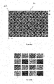
- Figure 3(a) presents a Color-Filter-Array (positioned on the sensor 104) which is commonly used to sample various colors with pixels performing a single measure.
- the most common CFA pattern is the Bayer pattern made of 2 by 2 elements (i.e. the representation by the matrix B mentioned previously).
- Figure 3(b) presents the sub-aperture images obtained from the micro-images 202. It appears that all the sub-aperture images are monochromatic.
- refocused images can be computed by summing-up the sub-aperture images S( ⁇ , ⁇ ) taking into consideration the disparity ⁇ focus for which objects at distance z focus are in focus.
- the 4D light field pixels S ( ⁇ , ⁇ , u, v ) are projected into the 2D refocused image.
- Preliminarily a refocused image R and a refocused image weight R weight are set to 0.
- the size of the refocused images [ N X , N Y ] is set to s times the size of the sub-aperture images.
- the projection is performed by summing the projected pixels at the coordinate (X, Y) into the refocused image.
- the refocused image weight is updated by adding 1 at the pixel coordinate ( X , Y ):
- R X Y + S ⁇ ⁇ u v
- R weight X Y + 1
- the refocused image weight records how many 4D light-field pixels have been projected per coordinate ( X, Y ). After projecting all 4D light-field pixels of S ( ⁇ , ⁇ , u, v ), the refocused image R is divided by the refocused image weight R weight . This last step harmonizes the number of pixels received per coordinate ( X, Y ).
- interpolation technique maps a non-integer pixel coordinate (X, Y) into the grid of the refocused image R and refocused image weight R weight (same interpolation function must be used when projecting into R and R weight ).
- Interpolation technique are commonly used, descriptions can be found in Bilinear Interpolation (http://en.wikipedia.org/wiki/Bilinear interpolation).
- Such remark concerning the refocusing that does not need to perform a demosacing operation can be generalized to the use of a CFA pattern made of a matrix of M ⁇ M elements each element being labeled c m,n with (m,n) ⁇ [0,M[ and with p (the diameter of the micro-images) equals to k ⁇ M, where k is an integer.
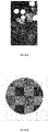
- Figure 4(a) illustrates a standard picture showing in focus part (bottom) and strongly de-focused light sources (top).
- the purpose of the plenoptic camera is not to render this light-source in focus. But at least this light-source observed with a strong de-focus should be observed without the Bayer pattern visible.
- the sub-aperture images are covered with the CFA of M 2 colors. But the starting colors of the sub-aperture image S uv is c u,v (and not c 0,0 for the common case where the original CFA is covering the pixels).
- shift color are performed as mentioned previously based on the equation c ( x + i ) mod 4,( y + j ) mod 4 for the pixel ( x, y, i, j ).
- Figure 5(b) presents sub-aperture images obtained from the processing of micro-lens images acquired via the configuration depicted in Figure 5(a) .
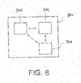
- Figure 6 presents an example of device that can be used to perform processing and refocusing of sub-aperture images based on micro-lens images disclosed in the present document.
- Such device referenced 900 comprises a computing unit (for example a CPU, for " Central Processing Unit " ), referenced 901, and one or more memory units (for example a RAM (for "Random Access Memory”) block in which intermediate results can be stored temporarily during the execution of instructions a computer program, or a ROM block in which, among other things, computer programs are stored, or an EEPROM (" Electrically-Erasable Programmable Read-Only Memory”) block, or a flash block) referenced 902. Computer programs are made of instructions that can be executed by the computing unit.
- Such device 900 can also comprise a dedicated unit, referenced 903, constituting an input-output interface to allow the device 900 to communicate with other devices.
- this dedicated unit 903 can be connected with an antenna (in order to perform communication without contacts), or with serial ports (to carry communications "contact”).
- the arrows in Figure 6 signify that the linked unit can exchange data through buses for example together.
- some or all of the steps of the method previously described can be implemented in hardware in a programmable FPGA ("Field Programmable Gate Array”) component or ASIC ("Application-Specific Integrated Circuit”) component.
- a programmable FPGA Field Programmable Gate Array
- ASIC Application-Specific Integrated Circuit
- the electronic device depicted in Figure 6 can be comprised in a camera device that is configure to capture images (i.e. a sampling of a light field). These images are stored on one or more memory units. Hence, these images can be viewed as bit stream data (i.e. a sequence of bits). Obviously, a bit stream can also be converted on byte stream and vice versa.
Description
- The disclosure relates to color filter array used in plenoptic camera. More precisely, the disclosure relates to a technique for avoiding color artifacts when refocusing is done, especially when bokeh is present in images.
- This section is intended to introduce the reader to various aspects of art, which may be related to various aspects of the present invention that are described and/or claimed below. This discussion is believed to be helpful in providing the reader with background information to facilitate a better understanding of the various aspects of the present invention. Accordingly, it should be understood that these statements are to be read in this light, and not as admissions of prior art.
- Even with plenoptic cameras, blur in some out-of-focus parts of an image still remain (and it is not possible to focus on in this places) due to the fact that these out-of-focus parts correspond to elements in the object space that are far from the focalization distance. In conventional photography, this blur is also named bokeh. As specified in Wikipédia for bokeh: "In out-of-focus areas, each point of light becomes an image of the aperture, generally a more or less round disc. Depending how a lens is corrected for spherical aberration, the disc may be uniformly illuminated, brighter near the edge, or brighter near the center. Lenses that are poorly corrected for spherical aberration will show one kind of disc for out-of-focus points in front of the plane of focus, and a different kind for points behind. This may actually be desirable, as blur circles that are dimmer near the edges produce less-defined shapes which blend smoothly with the surrounding image. The shape of the aperture has an influence on the subjective quality of bokeh as well. For conventional lens designs (with bladed apertures), when a lens is stopped down smaller than its maximum aperture size (minimum f-number), out-of-focus points are blurred into the polygonal shape formed by the aperture blades."
- It should be noted that "high quality" bokeh is viewed by most photographers as out of focus areas that are smooth rather than harsh. Moreover, in case of a color image, the quality of bokeh is linked to the homogeneity of colors in out-of-focus part of the image (i.e. without color artifacts). More details on Bokeh are described in the article entitled "A Technical View of Bokeh" by Harold M. Merklinger in Photo Techniques, May/june 1997, or in the technical note: "Depth of Field and Bokeh" by H.H. Nasse from the Camera Lens Division of the Zeiss company.
- The obtaining of color images from a plenoptic camera (as the one depicted in
Figure 1 ) generally involves a color demosaicing process that consists in determining, for each pixel sensor, the two color channel representations that have not been recorded by the sensor (i.e. the missing colors). Indeed, as for traditional digital cameras, a plenoptic camera comprises a color filter array (noted CFA) placed onto the image sensor so that each pixel only samples one of the three primary color values. Such Color Filter Array is usually a Bayer type CFA which is the repetition of a Bayer pattern that can be represented as a matrix
US 2014/0146201 presents a sensor recovered by a Color Filter array with the repetition of such Bayer pattern. Another Bayer pattern is represented by a matrix B =
- However, for a plenoptic camera, with a Color Filter array comprising the repetition of a Bayer pattern represented by a matrix of dimension MxM, and in the case that the size of the diameter of the micro-images (noted as p) is equal to k × M, where k is an integer, then it is not necessary to apply a color demosaicing process when obtaining a refocused image. Indeed, as detailed in
Figure 3(b) , in this configuration, the sub-apertures images obtained from such plenoptic camera are mono-chromatic, and as the refocusing process comprises the adding of these sub-apertures images, there is no need to perform a demosaicing. The refocusing can be viewed as a demosaicing less operation. - However, this architecture for a plenoptic camera has a drawback: the quality of bokeh in refocused images obtained from light field data acquired by such plenoptic camera is bad (due to the presence of color artifacts), especially during a refocusing process on other part of the image. These color artifacts are very difficult to correct, and occur each time some objects are observed out-of-focus by the main lens of a plenoptic camera. More precisely, a bokeh corresponding to a white circle form of a white light source point could display the Bayer pattern when refocusing, instead of keeping the same homogeneous color (see
Figures 4(a) and 4(b) of the present document). Another issue induced by such architecture is that when a change of viewpoint in images (especially in the extreme viewpoints) is done, as the subaperture images are monochromatic, it will not be possible to obtain a good demosaiced image. - For correcting such issue, one solution consists in applying a color filter array (based on a Bayer pattern) directly on the micro-lens of a plenoptic camera instead of positioning it on the sensor itself. Such technique is briefly described in
Figure 3 of the present document, or in theFigure 2 of documentUS 2015/0215593 .However, there is a need for a solution that does not need to change the position of a CFA from the sensors to the micro-lens. - One skilled in the art, trying to keep the CFA positioned on the sensor, would have breakdown the regularity of the CFA by using random patterns as mentioned in paragraph [0128] of document
US 2014/0146201 . - A patent application
US2010/128330A1 (hereafter D1) discloses several color coding patterns of a color filter array within an image capturing apparatus, in order to ease the demosaicing process. Such image capturing apparatus comprises a micro lens array that is arranged on a color filter array. D1 discloses a micro lens that is shared in units of four pixels. - A patent application
WO2012/117691A1 (hereafter D2) discloses an imaging device including a pixel array section in which a plurality of color pixels is arranged in a matrix form in two perpendicular directions. D2 discloses a multi-lens array disposed so that at least a part of the multi lens array allows the light to be incident on the adjacent color pixels which are different in one of the directions. - However, there is a need to determine which pattern configuration is well fitted for solving the previous mentioned problem.
- References in the specification to "one embodiment", "an embodiment", "an example embodiment", indicate that the embodiment described may include a particular feature, structure, or characteristic, but every embodiment may not necessarily include the particular feature, structure, or characteristic. Moreover, such phrases are not necessarily referring to the same embodiment. Further, when a particular feature, structure, or characteristic is described in connection with an embodiment, it is submitted that it is within the knowledge of one skilled in the art to affect such feature, structure, or characteristic in connection with other embodiments whether or not explicitly described.
- The present disclosure is directed to a plenoptic camera according to claim 1
- In a preferred embodiment, said color associated with a coefficient cm,n belongs to a group comprising cyan, yellow, green and magenta.
- In a preferred embodiment, the plenoptic camera is remarkable in that M = 2, and said initialization unit element is a CYYM (cyan, yellow, yellow and magenta) filter pattern.
- In a preferred embodiment, the plenoptic camera is remarkable in that M = 2, and said initialization unit element is a CYGM (cyan, yellow, green and magenta) filter pattern.
- In a preferred embodiment, the plenoptic camera is remarkable in that wherein k ≤ 4.
- The above and other aspects of the invention will become more apparent by the following detailed description of exemplary embodiments thereof with reference to the attached drawings in which:
-
Figure 1 present schematically the main components comprised in a plenoptic camera that enables the acquisition of light field data on which the present technique can be applied; -
Figure 2 present another view of the sensor array disclosed inFigure 1 ; -
Figure 3(a) presents a Color-Filter-Array (positioned on a sensor) which is commonly used to sample various colors with pixels performing a single measure; -
Figure 3(b) presents sub-aperture images obtained from the micro-images fromFigure 3(a) ; -
Figure 4(a) illustrates a standard picture showing in focus part (bottom) and strongly de-focused light sources (top); -
Figure 4(b) presents what appears at the level of strongly de-focused light sources when refocusing is performed; -
Figure 5(a) presents a Color Filter Array according to another embodiment of the disclosure; -
Figure 5(b) presents sub-aperture images obtained from the micro-images fromFigure 5(a) ; -
Figure 6 presents an example of device that can perform processing and refocusing of subaperture images based on micro-lens images disclosed in the present document. -
Figure 1 present schematically the main components comprised in a plenoptic camera that enables the acquisition of light field data on which the present technique can be applied. - More precisely, a plenoptic camera comprises a main lens referenced 101, and a sensor array (i.e. an array of pixel sensors (for example a sensor based on CMOS technology))., referenced 104. Between the
main lens 101 and thesensor array 104, a microlens array referenced 102, that comprises a set of micro lenses referenced 103, is positioned. It should be noted that optionally some spacers might be located between the micro-lens array around each lens and the sensor to prevent light from one lens to overlap with the light of other lenses at the sensor side. It should be noted that themain lens 101 can be a more complex optical system as the one depicted inFigure 1 (as for example the optical system described in Figures 12 and 13 of documentGB2488905 Figure 1 . The light rays passing through a micro-lens cover a part of the sensor array that records the radiance of these light rays. The recording by this part of the sensor defines a micro-lens image. -
Figure 2 present what thesensor array 104 records. Indeed, in such view, it appears that thesensor array 104 comprises a set of pixels, referenced 201. The light rays passing through a micro-lens cover a number ofpixels 201, and these pixels record the energy value of light rays that are incident/received. - Hence the
sensor array 104 of a plenoptic camera records an image which comprises a collection of 2D small images (i.e. the micro-lens images referenced 202) arranged within a 2D image (which is also named a raw 4D light-field image). Indeed, each small image (i.e. the microlens images) is produced by a micro-lens (the micro-lens can be identified by coordinates (i,j) from the array of lens). Hence, the pixels of the light-field are associated with 4 coordinates (x,y,i,j). L(x,y,i,j) being the 4D light-field recorded by the sensor illustrates the image which is recorded by the sensor. Each micro-lens produces a micro-image represented by a circle (the shape of the small image depends on the shape of the micro-lenses which is typically circular). Pixel coordinates (in the sensor array) are labelled (x,y). p is the distance between 2 consecutive micro-images, p is not necessary an integer value in general (however, in the present disclosure, we consider that p is an integer. For example, inFigure 2 , we have p = 4). Micro-lenses are chosen such that p is larger than a pixel size δ. Micro-lens images are referenced by their coordinate (i,j). Each micro-lens image samples the pupil of the main-lens with the (u,v) coordinate system. Some pixels might not receive any photons from any micro-lens especially if the shape of the micro-lenses is circular. In this case, the inter micro-lens space is masked out to prevent photons to pass outside from a micro-lens, resulting in some dark areas in the micro-images. If the micro-lenses have a square shape, no masking is needed). The center of a microlens image (i, j) is located on the sensor at the coordinate (xi,j,yi,j ). θ is the angle between the square lattice of pixel and the square lattice of micro-lenses, inFigure 2 θ = 0. Assuming the micro-lenses are arranged according to a regular square lattice, the (xi,j,yi,j ) can be computed by the following equation considering (x 0,0,y 0,0) the pixel coordinate of the micro-lens image (0,0):
-
Figure 2 also illustrates that an object from the scene is visible on several contiguous micro-lens images (dark dots). The distance between two consecutive views of an object is w, this distance is named the replication distance. Hence, an object is visible on r consecutive micro-lens images with :
- More details related to plenoptic camera can be found out in the
Section 4 entitled "Image formation of a Light field camera" in the article entitled " The Light Field Camera: Extended Depth of Field, Aliasing, and Superresolution" by Tom E. Bishop and Paolo Favaro, published in the IEEE Transactions on Pattern Analysis and Machine Intelligence, Vol. 34, N°5, in May 2012. - It should be noted that micro-images can be re-organized into the so-called sub-aperture images. A sub-aperture images collects all 4D light-field pixels (i.e. the pixels that are positioned on the sensor plane located behind the micro-lens) having the same (u, v) coordinates (the (u, v) coordinates correspond to coordinates on the main lens pupil).
- In view of the
Figure 2 , let (I, J) being the number of micro-lenses covering the sensor, and (Nx, Ny ) the number of pixels of the sensor. The number of sub-aperture images is equal to p × p. Each sub-aperture image have a size of (I,J) = (Nx/p, Ny/p) pixels. -
Figure 3(a) presents a Color-Filter-Array (positioned on the sensor 104) which is commonly used to sample various colors with pixels performing a single measure. The most common CFA pattern is the Bayer pattern made of 2 by 2 elements (i.e. the representation by the matrix B mentioned previously). For example, theFigure 3(a) presents a CFA which is made of the repetition of the matrix B, and where the size of the diameter of the micro-images 202 is equal to p = 4.Figure 3(b) presents the sub-aperture images obtained from the micro-images 202. It appears that all the sub-aperture images are monochromatic. - Therefore, in that case, the refocusing is particularly interesting.
- Indeed, usually, the refocusing of images can be done via the addition of sub-aperture images extracted/derived from the micro-images 204: refocused images can be computed by summing-up the sub-aperture images S(α, β) taking into consideration the disparity ρfocus for which objects at distance zfocus are in focus. The sub-aperture pixels positioned at coordinates (α, β) of the sub-aperture image S(α, β, u, v) are projected to the pixel at coordinate (X,Y) according to the following equation:

- The 4D light field pixels S(α, β, u, v) are projected into the 2D refocused image. Preliminarily a refocused image R and a refocused image weight Rweight are set to 0. The size of the refocused images [NX , NY ] is set to s times the size of the sub-aperture images. The projection is performed by summing the projected pixels at the coordinate (X, Y) into the refocused image. For each 4D light-field pixels projected, the refocused image weight is updated by adding 1 at the pixel coordinate (X, Y):

- The refocused image weight records how many 4D light-field pixels have been projected per coordinate (X, Y). After projecting all 4D light-field pixels of S(α, β, u, v), the refocused image R is divided by the refocused image weight Rweight. This last step harmonizes the number of pixels received per coordinate (X, Y).
- Since the projected coordinates (X, Y) are not necessarily integer coordinates, it is better to use interpolation technique to map a non-integer pixel coordinate (X, Y) into the grid of the refocused image R and refocused image weight Rweight (same interpolation function must be used when projecting into R and Rweight ). Interpolation technique are commonly used, descriptions can be found in Bilinear Interpolation (http://en.wikipedia.org/wiki/Bilinear interpolation).
- Hence, when ρfocus = 0 (or equivalently wfocus = ∞) the re-focused image is obtained by superposing (i.e. adding) the sub-aperture images with no shifts. More generally, the use of a common CFA monted on the sensor pixels delivers de-mosaiced images whatever is the refocusing parameter ρfocus. But this design is not able to produce good image for objects which remain out-of-focus (bokeh is affected by strong color artefacts).
- Such remark concerning the refocusing that does not need to perform a demosacing operation can be generalized to the use of a CFA pattern made of a matrix of M×M elements each element being labeled cm,n with (m,n)∈[0,M[ and with p (the diameter of the micro-images) equals to k × M, where k is an integer.
-
Figure 4(a) illustrates a standard picture showing in focus part (bottom) and strongly de-focused light sources (top). The strongly de-focused light-sources are actually showing the pupil of the main-lens since each light-source is like a Dirac function. If a plenoptic camera with a Bayer CFA set on top of the pixels with p = 4 then the re-focused image produced by the plenoptic camera will show/display content ofFigure 4(b) . - It is worth mentioning that in this case the purpose of the plenoptic camera is not to render this light-source in focus. But at least this light-source observed with a strong de-focus should be observed without the Bayer pattern visible.
- As mentioned previously, one solution to overcome such issue would be to put the color filter directly on the micro-lenses. However, it should be noted that the refocused image must be demosaiced for ρfocus = -M, 0, +M ... The proposed technique corresponds to a special CFA to be positioned on the sensor, in such way that the re-focused images are fully de-mosaiced for ρfocus = -M, 0, +M ....
- Indeed, the proposed technique relates to a CFA with a pattern of size M × M dedicated to a plenoptic camera with a micro-images having the size of p = kM (with θ = 0° the angle between the micro-lens array and the pixel array and k any positive integer).
- Let us consider a CFA pattern with M2 colors cm,n with (m, n) ∈ [0, M[. The color applied on the pixel (x, y, i, j) is set to c(x+i)modM,(y+j)modM. It results into a new CFA made of pM × pM covering the pixels. The original CFA is covering the p × p pixels, the other pixels belonging to the micro-lens (i, j) are covered with the original CFA but with "shuffled" colors.
- The sub-aperture images are covered with the CFA of M2 colors. But the starting colors of the sub-aperture image Suv is cu,v (and not c0,0 for the common case where the original CFA is covering the pixels). This design makes re-focused images to be perfectly de-mosaiced for ρfocus = -M, 0, +M ... Also this new design is not affected by color artifacts for object observed out-of-focus.
-
Figure 5(a) presents a Color Filter Array with a parameters p = 4, and M = 2 positioned on a sensor referenced 600, and where the micro-images are referenced 601. At the right top of the sensor, the pattern is represented by a matrix
-
Figure 5(b) presents sub-aperture images obtained from the processing of micro-lens images acquired via the configuration depicted inFigure 5(a) . -
Figure 6 presents an example of device that can be used to perform processing and refocusing of sub-aperture images based on micro-lens images disclosed in the present document. - Such device referenced 900 comprises a computing unit (for example a CPU, for "Central Processing Unit"), referenced 901, and one or more memory units (for example a RAM (for "Random Access Memory") block in which intermediate results can be stored temporarily during the execution of instructions a computer program, or a ROM block in which, among other things, computer programs are stored, or an EEPROM ("Electrically-Erasable Programmable Read-Only Memory") block, or a flash block) referenced 902. Computer programs are made of instructions that can be executed by the computing unit. Such device 900 can also comprise a dedicated unit, referenced 903, constituting an input-output interface to allow the device 900 to communicate with other devices. In particular, this
dedicated unit 903 can be connected with an antenna (in order to perform communication without contacts), or with serial ports (to carry communications "contact"). It should be noted that the arrows inFigure 6 signify that the linked unit can exchange data through buses for example together. - In an alternative embodiment, some or all of the steps of the method previously described, can be implemented in hardware in a programmable FPGA ("Field Programmable Gate Array") component or ASIC ("Application-Specific Integrated Circuit") component.
- In one embodiment of the disclosure, the electronic device depicted in
Figure 6 can be comprised in a camera device that is configure to capture images (i.e. a sampling of a light field). These images are stored on one or more memory units. Hence, these images can be viewed as bit stream data (i.e. a sequence of bits). Obviously, a bit stream can also be converted on byte stream and vice versa.
Claims (5)
- A plenoptic camera comprising a color filter array positioned on a sensor array (104, 600) comprising an array of pixels (201), the plenoptic camera being characterized in that said color filter array comprises a set of unit elements, each unit element covering M × M pixels of said sensor array (104, 600), with M an integer such that M ≥ 2, said plenoptic camera further comprising a set of micro-lenses (102), each micro-lens (103) delivering a micro-lens image (202, 601) on said sensor array (104, 600) with a diameter equal to p = k × M pixels, with k being an integer greater than or equal to two, wherein said set of unit elements comprises an initialization unit element being associated with a matrix

- The plenoptic camera, according to claim 1, wherein said color associated with a coefficient cm,n belongs to a group comprising cyan, yellow, green and magenta.
- The plenoptic camera according to claim 2, wherein M = 2, and said initialization unit element is a CYYM, cyan, yellow, yellow, magenta filter pattern.
- The plenoptic camera according to claim 2, wherein M = 2, and said initialization unit element is a CYGM, cyan, yellow, green, magenta filter pattern.
- The plenoptic camera, according to any claims 1 to 4, wherein k ≤ 4.
Priority Applications (2)
| Application Number | Priority Date | Filing Date | Title |
|---|---|---|---|
| EP15306297.1A EP3131292B1 (en) | 2015-08-14 | 2015-08-14 | Plenoptic camera comprising a shuffled color filter array |
| US15/236,470 US9807368B2 (en) | 2015-08-14 | 2016-08-14 | Plenoptic camera comprising a shuffled color filter array |
Applications Claiming Priority (1)
| Application Number | Priority Date | Filing Date | Title |
|---|---|---|---|
| EP15306297.1A EP3131292B1 (en) | 2015-08-14 | 2015-08-14 | Plenoptic camera comprising a shuffled color filter array |
Publications (2)
| Publication Number | Publication Date |
|---|---|
| EP3131292A1 EP3131292A1 (en) | 2017-02-15 |
| EP3131292B1 true EP3131292B1 (en) | 2022-06-15 |
Family
ID=54014752
Family Applications (1)
| Application Number | Title | Priority Date | Filing Date |
|---|---|---|---|
| EP15306297.1A Active EP3131292B1 (en) | 2015-08-14 | 2015-08-14 | Plenoptic camera comprising a shuffled color filter array |
Country Status (2)
| Country | Link |
|---|---|
| US (1) | US9807368B2 (en) |
| EP (1) | EP3131292B1 (en) |
Families Citing this family (5)
| Publication number | Priority date | Publication date | Assignee | Title |
|---|---|---|---|---|
| CN104864849B (en) * | 2014-02-24 | 2017-12-26 | 电信科学技术研究院 | Vision navigation method and device and robot |
| CA3214444A1 (en) | 2016-04-12 | 2017-10-19 | Quidient, Llc | Quotidian scene reconstruction engine |
| EP3522106A1 (en) | 2018-01-31 | 2019-08-07 | InterDigital CE Patent Holdings | A filter array enabling easy demosaicing |
| CN108428716A (en) * | 2018-02-12 | 2018-08-21 | 谢学军 | Augmented reality display system |
| US11875476B2 (en) | 2018-05-02 | 2024-01-16 | Quidient, Llc | Codec for processing scenes of almost unlimited detail |
Family Cites Families (18)
| Publication number | Priority date | Publication date | Assignee | Title |
|---|---|---|---|---|
| US8358354B2 (en) | 2009-01-26 | 2013-01-22 | The Board Of Trustees Of The Leland Stanford Junior University | Correction of optical abberations |
| US20090027527A1 (en) * | 2007-07-23 | 2009-01-29 | Visera Technologies Company Limited | Color filter arrays and image sensors using the same |
| KR101356698B1 (en) * | 2007-10-01 | 2014-01-29 | 삼성전자주식회사 | Image sensor for reducing crosstalk effect inter-pixel, and color filter array and image pickup apparatus thereof |
| JP4905326B2 (en) | 2007-11-12 | 2012-03-28 | ソニー株式会社 | Imaging device |
| JP5359465B2 (en) * | 2009-03-31 | 2013-12-04 | ソニー株式会社 | Solid-state imaging device, signal processing method for solid-state imaging device, and imaging device |
| US8228417B1 (en) | 2009-07-15 | 2012-07-24 | Adobe Systems Incorporated | Focused plenoptic camera employing different apertures or filtering at different microlenses |
| US8345144B1 (en) * | 2009-07-15 | 2013-01-01 | Adobe Systems Incorporated | Methods and apparatus for rich image capture with focused plenoptic cameras |
| JP5672989B2 (en) | 2010-11-05 | 2015-02-18 | ソニー株式会社 | Imaging device |
| EP2680592B1 (en) * | 2011-02-21 | 2016-04-06 | FUJIFILM Corporation | Color imaging device |
| JP2012195921A (en) * | 2011-02-28 | 2012-10-11 | Sony Corp | Solid-state imaging element and camera system |
| JP5623313B2 (en) | 2011-03-10 | 2014-11-12 | キヤノン株式会社 | Imaging apparatus and imaging optical system |
| WO2013169671A1 (en) | 2012-05-09 | 2013-11-14 | Lytro, Inc. | Optimization of optical systems for improved light field capture and manipulation |
| JP5740054B2 (en) * | 2012-07-06 | 2015-06-24 | 富士フイルム株式会社 | Imaging apparatus and image processing method |
| GB2505954B (en) | 2012-09-18 | 2017-05-24 | Canon Kk | Light field imaging device with a micro lens array integrating a sensor mounted with a colour-filter-array |
| JP5820794B2 (en) | 2012-10-05 | 2015-11-24 | オリンパス株式会社 | Imaging device |
| US9888194B2 (en) * | 2013-03-13 | 2018-02-06 | Fotonation Cayman Limited | Array camera architecture implementing quantum film image sensors |
| US9030580B2 (en) | 2013-09-28 | 2015-05-12 | Ricoh Company, Ltd. | Color filter modules for plenoptic XYZ imaging systems |
| JP6151632B2 (en) * | 2013-12-20 | 2017-06-21 | 富士フイルム株式会社 | Imaging module and imaging apparatus |
-
2015
- 2015-08-14 EP EP15306297.1A patent/EP3131292B1/en active Active
-
2016
- 2016-08-14 US US15/236,470 patent/US9807368B2/en active Active
Also Published As
| Publication number | Publication date |
|---|---|
| US9807368B2 (en) | 2017-10-31 |
| US20170048513A1 (en) | 2017-02-16 |
| EP3131292A1 (en) | 2017-02-15 |
Similar Documents
| Publication | Publication Date | Title |
|---|---|---|
| US9807368B2 (en) | Plenoptic camera comprising a shuffled color filter array | |
| CN204498282U (en) | There is the imaging system of visible ray photosensitive pixel and infrared light photosensitive pixel | |
| US10334229B2 (en) | Method for obtaining a refocused image from a 4D raw light field data using a shift correction parameter | |
| US9549157B2 (en) | Imaging apparatus, image processing method, and program | |
| JP6887223B2 (en) | Plenoptic Forbidden Camera | |
| EP2630788A1 (en) | System and method for imaging using multi aperture camera | |
| JP5904281B2 (en) | Image processing method, image processing apparatus, imaging apparatus, and image processing program | |
| EP3098779B1 (en) | Method for obtaining a refocused image from 4d raw light field data | |
| CN111353948A (en) | Image noise reduction method, device and equipment | |
| CN103688536A (en) | Image processing device, image processing method, and program | |
| US10366478B2 (en) | Method and device for obtaining a HDR image by graph signal processing | |
| JP4968527B2 (en) | Imaging device | |
| US7221793B2 (en) | Systems and methods for providing spatially-varied demosaicing | |
| US20150268392A1 (en) | Filter-array-equipped microlens and solid-state imaging device | |
| US20070252908A1 (en) | Method of Creating Colour Image, Imaging Device and Imaging Module | |
| JP2018170757A (en) | Image generating apparatus and imaging apparatus | |
| CN101883289A (en) | Parallax reservation and parallax elimination in imaging systems of multiple-lens and multiple-sensor | |
| EP3746978B1 (en) | A filter array for demosaicing | |
| EP3104604A1 (en) | Light field imaging device | |
| CN106852190B (en) | Image processing unit, filming apparatus and image processing method | |
| US20240127407A1 (en) | Image sensor apparatus for capturing depth information | |
| EP3200151A1 (en) | Method and device for obtaining a depth map | |
| KR20230111379A (en) | Image sensor and imaging device | |
| US9894336B2 (en) | Color imaging using a monochromatic digital camera |
Legal Events
| Date | Code | Title | Description |
|---|---|---|---|
| PUAI | Public reference made under article 153(3) epc to a published international application that has entered the european phase |
Free format text: ORIGINAL CODE: 0009012 |
|
| STAA | Information on the status of an ep patent application or granted ep patent |
Free format text: STATUS: THE APPLICATION HAS BEEN PUBLISHED |
|
| AK | Designated contracting states |
Kind code of ref document: A1 Designated state(s): AL AT BE BG CH CY CZ DE DK EE ES FI FR GB GR HR HU IE IS IT LI LT LU LV MC MK MT NL NO PL PT RO RS SE SI SK SM TR |
|
| AX | Request for extension of the european patent |
Extension state: BA ME |
|
| STAA | Information on the status of an ep patent application or granted ep patent |
Free format text: STATUS: REQUEST FOR EXAMINATION WAS MADE |
|
| 17P | Request for examination filed |
Effective date: 20170801 |
|
| RBV | Designated contracting states (corrected) |
Designated state(s): AL AT BE BG CH CY CZ DE DK EE ES FI FR GB GR HR HU IE IS IT LI LT LU LV MC MK MT NL NO PL PT RO RS SE SI SK SM TR |
|
| RAP1 | Party data changed (applicant data changed or rights of an application transferred) |
Owner name: INTERDIGITAL CE PATENT HOLDINGS |
|
| STAA | Information on the status of an ep patent application or granted ep patent |
Free format text: STATUS: EXAMINATION IS IN PROGRESS |
|
| 17Q | First examination report despatched |
Effective date: 20190626 |
|
| STAA | Information on the status of an ep patent application or granted ep patent |
Free format text: STATUS: EXAMINATION IS IN PROGRESS |
|
| STAA | Information on the status of an ep patent application or granted ep patent |
Free format text: STATUS: EXAMINATION IS IN PROGRESS |
|
| REG | Reference to a national code |
Ref country code: DE Ref legal event code: R079 Ref document number: 602015079452 Country of ref document: DE Free format text: PREVIOUS MAIN CLASS: H04N0013020000 Ipc: H04N0013232000 |
|
| RIC1 | Information provided on ipc code assigned before grant |
Ipc: G06T 3/40 20060101ALI20211216BHEP Ipc: H04N 13/257 20180101ALI20211216BHEP Ipc: H04N 13/207 20180101ALI20211216BHEP Ipc: H04N 13/232 20180101AFI20211216BHEP |
|
| GRAP | Despatch of communication of intention to grant a patent |
Free format text: ORIGINAL CODE: EPIDOSNIGR1 |
|
| STAA | Information on the status of an ep patent application or granted ep patent |
Free format text: STATUS: GRANT OF PATENT IS INTENDED |
|
| INTG | Intention to grant announced |
Effective date: 20220216 |
|
| GRAS | Grant fee paid |
Free format text: ORIGINAL CODE: EPIDOSNIGR3 |
|
| GRAA | (expected) grant |
Free format text: ORIGINAL CODE: 0009210 |
|
| STAA | Information on the status of an ep patent application or granted ep patent |
Free format text: STATUS: THE PATENT HAS BEEN GRANTED |
|
| AK | Designated contracting states |
Kind code of ref document: B1 Designated state(s): AL AT BE BG CH CY CZ DE DK EE ES FI FR GB GR HR HU IE IS IT LI LT LU LV MC MK MT NL NO PL PT RO RS SE SI SK SM TR |
|
| REG | Reference to a national code |
Ref country code: CH Ref legal event code: EP Ref country code: GB Ref legal event code: FG4D |
|
| REG | Reference to a national code |
Ref country code: IE Ref legal event code: FG4D |
|
| REG | Reference to a national code |
Ref country code: DE Ref legal event code: R096 Ref document number: 602015079452 Country of ref document: DE |
|
| REG | Reference to a national code |
Ref country code: AT Ref legal event code: REF Ref document number: 1499104 Country of ref document: AT Kind code of ref document: T Effective date: 20220715 |
|
| REG | Reference to a national code |
Ref country code: NL Ref legal event code: FP |
|
| REG | Reference to a national code |
Ref country code: LT Ref legal event code: MG9D |
|
| PG25 | Lapsed in a contracting state [announced via postgrant information from national office to epo] |
Ref country code: SE Free format text: LAPSE BECAUSE OF FAILURE TO SUBMIT A TRANSLATION OF THE DESCRIPTION OR TO PAY THE FEE WITHIN THE PRESCRIBED TIME-LIMIT Effective date: 20220615 Ref country code: NO Free format text: LAPSE BECAUSE OF FAILURE TO SUBMIT A TRANSLATION OF THE DESCRIPTION OR TO PAY THE FEE WITHIN THE PRESCRIBED TIME-LIMIT Effective date: 20220915 Ref country code: LT Free format text: LAPSE BECAUSE OF FAILURE TO SUBMIT A TRANSLATION OF THE DESCRIPTION OR TO PAY THE FEE WITHIN THE PRESCRIBED TIME-LIMIT Effective date: 20220615 Ref country code: HR Free format text: LAPSE BECAUSE OF FAILURE TO SUBMIT A TRANSLATION OF THE DESCRIPTION OR TO PAY THE FEE WITHIN THE PRESCRIBED TIME-LIMIT Effective date: 20220615 Ref country code: GR Free format text: LAPSE BECAUSE OF FAILURE TO SUBMIT A TRANSLATION OF THE DESCRIPTION OR TO PAY THE FEE WITHIN THE PRESCRIBED TIME-LIMIT Effective date: 20220916 Ref country code: FI Free format text: LAPSE BECAUSE OF FAILURE TO SUBMIT A TRANSLATION OF THE DESCRIPTION OR TO PAY THE FEE WITHIN THE PRESCRIBED TIME-LIMIT Effective date: 20220615 Ref country code: BG Free format text: LAPSE BECAUSE OF FAILURE TO SUBMIT A TRANSLATION OF THE DESCRIPTION OR TO PAY THE FEE WITHIN THE PRESCRIBED TIME-LIMIT Effective date: 20220915 |
|
| REG | Reference to a national code |
Ref country code: AT Ref legal event code: MK05 Ref document number: 1499104 Country of ref document: AT Kind code of ref document: T Effective date: 20220615 |
|
| PG25 | Lapsed in a contracting state [announced via postgrant information from national office to epo] |
Ref country code: RS Free format text: LAPSE BECAUSE OF FAILURE TO SUBMIT A TRANSLATION OF THE DESCRIPTION OR TO PAY THE FEE WITHIN THE PRESCRIBED TIME-LIMIT Effective date: 20220615 Ref country code: LV Free format text: LAPSE BECAUSE OF FAILURE TO SUBMIT A TRANSLATION OF THE DESCRIPTION OR TO PAY THE FEE WITHIN THE PRESCRIBED TIME-LIMIT Effective date: 20220615 |
|
| PG25 | Lapsed in a contracting state [announced via postgrant information from national office to epo] |
Ref country code: SM Free format text: LAPSE BECAUSE OF FAILURE TO SUBMIT A TRANSLATION OF THE DESCRIPTION OR TO PAY THE FEE WITHIN THE PRESCRIBED TIME-LIMIT Effective date: 20220615 Ref country code: SK Free format text: LAPSE BECAUSE OF FAILURE TO SUBMIT A TRANSLATION OF THE DESCRIPTION OR TO PAY THE FEE WITHIN THE PRESCRIBED TIME-LIMIT Effective date: 20220615 Ref country code: RO Free format text: LAPSE BECAUSE OF FAILURE TO SUBMIT A TRANSLATION OF THE DESCRIPTION OR TO PAY THE FEE WITHIN THE PRESCRIBED TIME-LIMIT Effective date: 20220615 Ref country code: PT Free format text: LAPSE BECAUSE OF FAILURE TO SUBMIT A TRANSLATION OF THE DESCRIPTION OR TO PAY THE FEE WITHIN THE PRESCRIBED TIME-LIMIT Effective date: 20221017 Ref country code: ES Free format text: LAPSE BECAUSE OF FAILURE TO SUBMIT A TRANSLATION OF THE DESCRIPTION OR TO PAY THE FEE WITHIN THE PRESCRIBED TIME-LIMIT Effective date: 20220615 Ref country code: EE Free format text: LAPSE BECAUSE OF FAILURE TO SUBMIT A TRANSLATION OF THE DESCRIPTION OR TO PAY THE FEE WITHIN THE PRESCRIBED TIME-LIMIT Effective date: 20220615 Ref country code: CZ Free format text: LAPSE BECAUSE OF FAILURE TO SUBMIT A TRANSLATION OF THE DESCRIPTION OR TO PAY THE FEE WITHIN THE PRESCRIBED TIME-LIMIT Effective date: 20220615 Ref country code: AT Free format text: LAPSE BECAUSE OF FAILURE TO SUBMIT A TRANSLATION OF THE DESCRIPTION OR TO PAY THE FEE WITHIN THE PRESCRIBED TIME-LIMIT Effective date: 20220615 |
|
| PG25 | Lapsed in a contracting state [announced via postgrant information from national office to epo] |
Ref country code: PL Free format text: LAPSE BECAUSE OF FAILURE TO SUBMIT A TRANSLATION OF THE DESCRIPTION OR TO PAY THE FEE WITHIN THE PRESCRIBED TIME-LIMIT Effective date: 20220615 Ref country code: IS Free format text: LAPSE BECAUSE OF FAILURE TO SUBMIT A TRANSLATION OF THE DESCRIPTION OR TO PAY THE FEE WITHIN THE PRESCRIBED TIME-LIMIT Effective date: 20221015 |
|
| REG | Reference to a national code |
Ref country code: DE Ref legal event code: R097 Ref document number: 602015079452 Country of ref document: DE |
|
| PG25 | Lapsed in a contracting state [announced via postgrant information from national office to epo] |
Ref country code: MC Free format text: LAPSE BECAUSE OF FAILURE TO SUBMIT A TRANSLATION OF THE DESCRIPTION OR TO PAY THE FEE WITHIN THE PRESCRIBED TIME-LIMIT Effective date: 20220615 Ref country code: AL Free format text: LAPSE BECAUSE OF FAILURE TO SUBMIT A TRANSLATION OF THE DESCRIPTION OR TO PAY THE FEE WITHIN THE PRESCRIBED TIME-LIMIT Effective date: 20220615 |
|
| REG | Reference to a national code |
Ref country code: CH Ref legal event code: PL |
|
| PLBE | No opposition filed within time limit |
Free format text: ORIGINAL CODE: 0009261 |
|
| STAA | Information on the status of an ep patent application or granted ep patent |
Free format text: STATUS: NO OPPOSITION FILED WITHIN TIME LIMIT |
|
| PG25 | Lapsed in a contracting state [announced via postgrant information from national office to epo] |
Ref country code: LU Free format text: LAPSE BECAUSE OF NON-PAYMENT OF DUE FEES Effective date: 20220814 Ref country code: LI Free format text: LAPSE BECAUSE OF NON-PAYMENT OF DUE FEES Effective date: 20220831 Ref country code: DK Free format text: LAPSE BECAUSE OF FAILURE TO SUBMIT A TRANSLATION OF THE DESCRIPTION OR TO PAY THE FEE WITHIN THE PRESCRIBED TIME-LIMIT Effective date: 20220615 Ref country code: CH Free format text: LAPSE BECAUSE OF NON-PAYMENT OF DUE FEES Effective date: 20220831 |
|
| REG | Reference to a national code |
Ref country code: BE Ref legal event code: MM Effective date: 20220831 |
|
| 26N | No opposition filed |
Effective date: 20230316 |
|
| PG25 | Lapsed in a contracting state [announced via postgrant information from national office to epo] |
Ref country code: SI Free format text: LAPSE BECAUSE OF FAILURE TO SUBMIT A TRANSLATION OF THE DESCRIPTION OR TO PAY THE FEE WITHIN THE PRESCRIBED TIME-LIMIT Effective date: 20220615 |
|
| P01 | Opt-out of the competence of the unified patent court (upc) registered |
Effective date: 20230511 |
|
| PG25 | Lapsed in a contracting state [announced via postgrant information from national office to epo] |
Ref country code: IE Free format text: LAPSE BECAUSE OF NON-PAYMENT OF DUE FEES Effective date: 20220814 |
|
| PG25 | Lapsed in a contracting state [announced via postgrant information from national office to epo] |
Ref country code: BE Free format text: LAPSE BECAUSE OF NON-PAYMENT OF DUE FEES Effective date: 20220831 |
|
| PGFP | Annual fee paid to national office [announced via postgrant information from national office to epo] |
Ref country code: NL Payment date: 20230825 Year of fee payment: 9 |
|
| PGFP | Annual fee paid to national office [announced via postgrant information from national office to epo] |
Ref country code: GB Payment date: 20230822 Year of fee payment: 9 |
|
| PGFP | Annual fee paid to national office [announced via postgrant information from national office to epo] |
Ref country code: FR Payment date: 20230824 Year of fee payment: 9 Ref country code: DE Payment date: 20230828 Year of fee payment: 9 |
|
| PG25 | Lapsed in a contracting state [announced via postgrant information from national office to epo] |
Ref country code: IT Free format text: LAPSE BECAUSE OF FAILURE TO SUBMIT A TRANSLATION OF THE DESCRIPTION OR TO PAY THE FEE WITHIN THE PRESCRIBED TIME-LIMIT Effective date: 20220615 |
|
| PG25 | Lapsed in a contracting state [announced via postgrant information from national office to epo] |
Ref country code: HU Free format text: LAPSE BECAUSE OF FAILURE TO SUBMIT A TRANSLATION OF THE DESCRIPTION OR TO PAY THE FEE WITHIN THE PRESCRIBED TIME-LIMIT; INVALID AB INITIO Effective date: 20150814 |