WO2014003140A1 - 複合半透膜および複合半透膜エレメント - Google Patents
複合半透膜および複合半透膜エレメント Download PDFInfo
- Publication number
- WO2014003140A1 WO2014003140A1 PCT/JP2013/067717 JP2013067717W WO2014003140A1 WO 2014003140 A1 WO2014003140 A1 WO 2014003140A1 JP 2013067717 W JP2013067717 W JP 2013067717W WO 2014003140 A1 WO2014003140 A1 WO 2014003140A1
- Authority
- WO
- WIPO (PCT)
- Prior art keywords
- composite semipermeable
- semipermeable membrane
- layer
- membrane
- polymer solution
- Prior art date
- Legal status (The legal status is an assumption and is not a legal conclusion. Google has not performed a legal analysis and makes no representation as to the accuracy of the status listed.)
- Ceased
Links
Images

Classifications
-
- B—PERFORMING OPERATIONS; TRANSPORTING
- B01—PHYSICAL OR CHEMICAL PROCESSES OR APPARATUS IN GENERAL
- B01D—SEPARATION
- B01D69/00—Semi-permeable membranes for separation processes or apparatus characterised by their form, structure or properties; Manufacturing processes specially adapted therefor
- B01D69/10—Supported membranes; Membrane supports
- B01D69/107—Organic support material
- B01D69/1071—Woven, non-woven or net mesh
-
- B—PERFORMING OPERATIONS; TRANSPORTING
- B01—PHYSICAL OR CHEMICAL PROCESSES OR APPARATUS IN GENERAL
- B01D—SEPARATION
- B01D61/00—Processes of separation using semi-permeable membranes, e.g. dialysis, osmosis or ultrafiltration; Apparatus, accessories or auxiliary operations specially adapted therefor
- B01D61/02—Reverse osmosis; Hyperfiltration ; Nanofiltration
- B01D61/025—Reverse osmosis; Hyperfiltration
-
- B—PERFORMING OPERATIONS; TRANSPORTING
- B01—PHYSICAL OR CHEMICAL PROCESSES OR APPARATUS IN GENERAL
- B01D—SEPARATION
- B01D61/00—Processes of separation using semi-permeable membranes, e.g. dialysis, osmosis or ultrafiltration; Apparatus, accessories or auxiliary operations specially adapted therefor
- B01D61/02—Reverse osmosis; Hyperfiltration ; Nanofiltration
- B01D61/027—Nanofiltration
-
- B—PERFORMING OPERATIONS; TRANSPORTING
- B01—PHYSICAL OR CHEMICAL PROCESSES OR APPARATUS IN GENERAL
- B01D—SEPARATION
- B01D65/00—Accessories or auxiliary operations, in general, for separation processes or apparatus using semi-permeable membranes
- B01D65/08—Prevention of membrane fouling or of concentration polarisation
-
- B—PERFORMING OPERATIONS; TRANSPORTING
- B01—PHYSICAL OR CHEMICAL PROCESSES OR APPARATUS IN GENERAL
- B01D—SEPARATION
- B01D69/00—Semi-permeable membranes for separation processes or apparatus characterised by their form, structure or properties; Manufacturing processes specially adapted therefor
- B01D69/02—Semi-permeable membranes for separation processes or apparatus characterised by their form, structure or properties; Manufacturing processes specially adapted therefor characterised by their properties
-
- B—PERFORMING OPERATIONS; TRANSPORTING
- B01—PHYSICAL OR CHEMICAL PROCESSES OR APPARATUS IN GENERAL
- B01D—SEPARATION
- B01D69/00—Semi-permeable membranes for separation processes or apparatus characterised by their form, structure or properties; Manufacturing processes specially adapted therefor
- B01D69/12—Composite membranes; Ultra-thin membranes
- B01D69/1214—Chemically bonded layers, e.g. cross-linking
-
- B—PERFORMING OPERATIONS; TRANSPORTING
- B01—PHYSICAL OR CHEMICAL PROCESSES OR APPARATUS IN GENERAL
- B01D—SEPARATION
- B01D69/00—Semi-permeable membranes for separation processes or apparatus characterised by their form, structure or properties; Manufacturing processes specially adapted therefor
- B01D69/12—Composite membranes; Ultra-thin membranes
- B01D69/125—In situ manufacturing by polymerisation, polycondensation, cross-linking or chemical reaction
-
- B—PERFORMING OPERATIONS; TRANSPORTING
- B01—PHYSICAL OR CHEMICAL PROCESSES OR APPARATUS IN GENERAL
- B01D—SEPARATION
- B01D71/00—Semi-permeable membranes for separation processes or apparatus characterised by the material; Manufacturing processes specially adapted therefor
- B01D71/06—Organic material
- B01D71/56—Polyamides, e.g. polyester-amides
-
- C—CHEMISTRY; METALLURGY
- C02—TREATMENT OF WATER, WASTE WATER, SEWAGE, OR SLUDGE
- C02F—TREATMENT OF WATER, WASTE WATER, SEWAGE, OR SLUDGE
- C02F1/00—Treatment of water, waste water, or sewage
- C02F1/44—Treatment of water, waste water, or sewage by dialysis, osmosis or reverse osmosis
- C02F1/441—Treatment of water, waste water, or sewage by dialysis, osmosis or reverse osmosis by reverse osmosis
-
- C—CHEMISTRY; METALLURGY
- C02—TREATMENT OF WATER, WASTE WATER, SEWAGE, OR SLUDGE
- C02F—TREATMENT OF WATER, WASTE WATER, SEWAGE, OR SLUDGE
- C02F1/00—Treatment of water, waste water, or sewage
- C02F1/44—Treatment of water, waste water, or sewage by dialysis, osmosis or reverse osmosis
- C02F1/442—Treatment of water, waste water, or sewage by dialysis, osmosis or reverse osmosis by nanofiltration
-
- B—PERFORMING OPERATIONS; TRANSPORTING
- B01—PHYSICAL OR CHEMICAL PROCESSES OR APPARATUS IN GENERAL
- B01D—SEPARATION
- B01D2325/00—Details relating to properties of membranes
- B01D2325/04—Characteristic thickness
-
- B—PERFORMING OPERATIONS; TRANSPORTING
- B01—PHYSICAL OR CHEMICAL PROCESSES OR APPARATUS IN GENERAL
- B01D—SEPARATION
- B01D2325/00—Details relating to properties of membranes
- B01D2325/06—Surface irregularities
-
- B—PERFORMING OPERATIONS; TRANSPORTING
- B01—PHYSICAL OR CHEMICAL PROCESSES OR APPARATUS IN GENERAL
- B01D—SEPARATION
- B01D2325/00—Details relating to properties of membranes
- B01D2325/20—Specific permeability or cut-off range
-
- B—PERFORMING OPERATIONS; TRANSPORTING
- B01—PHYSICAL OR CHEMICAL PROCESSES OR APPARATUS IN GENERAL
- B01D—SEPARATION
- B01D2325/00—Details relating to properties of membranes
- B01D2325/28—Degradation or stability over time
-
- C—CHEMISTRY; METALLURGY
- C02—TREATMENT OF WATER, WASTE WATER, SEWAGE, OR SLUDGE
- C02F—TREATMENT OF WATER, WASTE WATER, SEWAGE, OR SLUDGE
- C02F2103/00—Nature of the water, waste water, sewage or sludge to be treated
- C02F2103/08—Seawater, e.g. for desalination
Definitions
- the present invention relates to a composite semipermeable membrane and a composite semipermeable membrane element useful for selective separation of a liquid mixture.
- the composite semipermeable membrane obtained by the present invention can be suitably used for desalination of seawater and brine, for example.
- Membranes used in membrane separation methods include microfiltration membranes, ultrafiltration membranes, nanofiltration membranes, and reverse osmosis membranes. These membranes can be used for beverages such as seawater, brine, and water containing harmful substances. It is used to obtain water, to manufacture industrial ultrapure water, to treat wastewater, to recover valuable materials.
- an object of the present invention is to provide a composite semipermeable membrane and a composite semipermeable membrane element that are low in performance degradation due to fouling while at the same time achieving both high salt removal and high water permeability.
- the present inventors have determined that a composite half provided with a support membrane having a base material and a porous support layer, and a separation functional layer provided on the support membrane.
- the permeable membrane in each of 10 sections having a width of 2.0 ⁇ m in the direction of the membrane surface of the composite semipermeable membrane, the height of one-fifth or more of the 10-point average surface roughness of the separation functional layer is It has been found that the above-mentioned problems can be solved when the standard deviation of the height of the protrusions is 60 nm or less, and the present invention has been completed.
- the gist of the present invention is as follows.
- a composite semipermeable membrane comprising a base material and a support membrane having a porous support layer provided on the base material, and a separation functional layer provided on the support membrane, the electron microscope When observing arbitrary 10 cross sections having a length of 2.0 ⁇ m in the film surface direction of the composite semipermeable membrane, 5 minutes of the average surface roughness of 10 points in the separation functional layer in each cross section
- a composite semipermeable membrane having a standard deviation of the height of protrusions having a height of 1 or more of 60 nm or less.
- ⁇ 2> The composite semipermeable membrane according to ⁇ 1>, wherein an average pore radius in the separation functional layer measured by a positron annihilation lifetime measurement method is 0.300 nm or more and 0.400 nm or less.
- ⁇ 3> The composite semipermeable membrane according to ⁇ 1> or ⁇ 2>, wherein an average height of the protrusions in each cross section is 100 nm or more and 300 nm or less.
- ⁇ 4> The composite semipermeable membrane according to any one of ⁇ 1> to ⁇ 3>, wherein an average number density of the protrusions in each cross section is 10.0 pieces / ⁇ m or more and 30.0 pieces / ⁇ m or less. .
- the porous support layer has a multilayer structure of a first layer on the base material side and a second layer formed thereon, and the polymer solution A and the second layer forming the first layer ⁇ 1> to ⁇ 4>, wherein the polymer solution B for forming a layer is applied on the substrate at the same time, and then contacted with a coagulation bath and phase-separated.
- Composite semipermeable membrane ⁇ 6> The composite semipermeable membrane according to ⁇ 5>, wherein the solid content concentration b (% by weight) of the polymer solution B is more than 25% by weight and 35% by weight or less.
- the composite semipermeable membrane according to any one of the above items ⁇ 1> to ⁇ 8> is disposed around a cylindrical water collecting pipe having a large number of holes, together with the raw water channel material and the permeate channel material.
- a composite semipermeable membrane and a composite semipermeable membrane element are realized in which high salt removal property and high water permeability are compatible and performance degradation due to fouling is small.
- FIG. 1 is a drawing schematically showing a method for measuring the protrusion height of the separation functional layer.
- the composite semipermeable membrane includes a base material and a support membrane including a porous support layer provided on the base material, and a separation functional layer provided on the porous support layer.
- (1-1) Separation Function Layer The separation function layer is a layer that plays a role of separating the solute in the composite semipermeable membrane.
- the composition such as the composition and thickness of the separation functional layer is set in accordance with the intended use of the composite semipermeable membrane. As noted above, the performance of conventional membranes may be reduced by use.
- the separation function layer having a pleat structure has a standard deviation of the height of the folds (projections) of 60 nm or less, and the performance of the composite semipermeable membrane.
- the decline was suppressed. This is considered to be because the deposition of fouling substances such as organic substances and colloids is suppressed by making the heights of the protrusions uniform.
- the standard deviation of the height of the protrusion the standard deviation value of the height of the protrusion having a height of one fifth or more of the 10-point average surface roughness using an electron microscope is used. A method for measuring the 10-point average surface roughness will be described later.
- Japanese Patent Application Laid-Open No. 11-226367 proposes a method of forming a surface layer containing a crosslinked organic polymer having a nonionic hydrophilic group on a reverse osmosis composite membrane. ing.
- the height and number density of the protrusions are values measured for protrusions having a height of 1/5 or more of the 10-point average surface roughness. This will be described in detail below.
- the 10-point average surface roughness is a value obtained by the following calculation method. First, a cross-sectional image is obtained by observing a cross section perpendicular to the film surface with an electron microscope at the following magnification. In the obtained cross-sectional image, the surface of the separation functional layer (indicated by reference numeral “1” in FIG. 1) appears as a curve of a pleated structure in which convex portions and concave portions are continuously repeated.
- a roughness curve defined by ISO 4287: 1997 is obtained for a region having a width of 2.0 ⁇ m in the film surface direction (direction parallel to the film surface) of the composite semipermeable membrane in the cross-sectional image.
- a cross-sectional image is extracted with a width of 2.0 ⁇ m in the direction of the average line of the roughness curve (FIG. 1).
- the average line is a straight line defined based on ISO 4287: 1997, and is drawn so that the total area of the region surrounded by the average line and the roughness curve is equal above and below the average line in the measurement length. Straight line.
- the height of the peak of the protrusion and the depth of the valley in the separation functional layer are measured using the average line as a reference line. Calculate the average value for the absolute values of the heights H1 to H5 of the five peaks from the highest peak to the fifth, and calculate the average values for the absolute values of the depths D1 to D5 of the five valley peaks from the deepest valley Further, the sum of the absolute values of the two average values obtained is calculated. The sum thus obtained is the 10-point average surface roughness.
- the reference line is drawn in parallel to the horizontal direction for convenience of explanation.
- the cross section of the separation functional layer can be observed with a scanning electron microscope or a transmission electron microscope.
- a scanning electron microscope the composite semipermeable membrane sample is thinly coated with platinum, platinum-palladium or ruthenium tetroxide, preferably ruthenium tetroxide, and a high resolution field emission type with an acceleration voltage of 3 to 6 kV.
- Observation is performed using a scanning electron microscope (UHR-FE-SEM).
- As the high-resolution field emission scanning electron microscope Hitachi S-900 electron microscope can be used.
- the observation magnification is preferably 5,000 to 100,000 times, and preferably 10,000 to 50,000 times for obtaining the height of the protrusions. In the obtained electron micrograph, the height of the protrusion can be directly measured with a scale or the like in consideration of the observation magnification.
- the average number density of protrusions is measured as follows. In the composite semipermeable membrane, when arbitrary cross sections are observed, projections having a height of 1/5 or more of the above-mentioned 10-point average surface roughness are counted in each cross section. The number density in each cross section (that is, the number of protrusions per 1 ⁇ m) is calculated, and the arithmetic average value is calculated from the number density in 10 cross sections to obtain the average number density.
- each cross section has a width of 2.0 ⁇ m in the direction of the average line of the roughness curve.
- the average height of the protrusions is measured as follows. In the composite semipermeable membrane, when any cross section at 10 locations is observed, in each cross section, the height of the protrusion which is 1/5 or more of the above-mentioned 10-point average surface roughness is measured. Calculate the average height per protrusion. Furthermore, the average height is obtained by calculating the arithmetic average based on the calculation results for the 10 cross sections.
- each cross section has a width of 2.0 ⁇ m in the direction of the average line of the roughness curve.
- the standard deviation of the height of the protrusion is calculated based on the height of the protrusion which is 1/5 or more of the 10-point average surface roughness measured in 10 cross sections, like the average height.
- the average height of the protrusions of the separation functional layer is preferably 100 nm or more, more preferably 110 nm or more. When the average height of the protrusions is 100 nm or more, a composite semipermeable membrane having sufficient water permeability can be easily obtained. Moreover, the average height of the protrusions of the separation functional layer is preferably 1000 nm or less, more preferably 800 nm or less, and still more preferably 300 nm or less. When the average height of the protrusions is 1000 nm or less, the protrusions are not crushed even when the composite semipermeable membrane is operated at a high pressure, and the average height of the protrusions is 800 nm or less. It is easy to obtain a film having a small standard deviation in height, and stable film performance can be obtained. Furthermore, when the average height of the protrusions is 300 nm or less, stable film performance can be maintained for a long time.
- the average number density of protrusions in the separation functional layer is preferably 10.0 pieces / ⁇ m or more, more preferably 12.0 pieces / ⁇ m or more.
- the composite semipermeable membrane can obtain sufficient water permeability, and further, deformation of protrusions during pressing can be suppressed, and stable membrane performance can be obtained. It is done.
- the average number density of protrusions of the separation functional layer is preferably 50.0 pieces / ⁇ m or less, more preferably 40.0 pieces / ⁇ m or less, and further preferably 30.0 pieces / ⁇ m or less. .
- the protrusions are sufficiently grown, and a composite semipermeable membrane having desired water permeability can be easily obtained.
- the average number density is 40.0 pieces / ⁇ m or less, a film having a smaller standard deviation of the height of the protrusions can be obtained, and the average number density is 30.0 pieces / ⁇ m or less.
- the average number density of the protrusions of the separation functional layer can be observed by the same method as that for observing the average height of the protrusions.
- the standard deviation of the height of the protrusion having a height of 1/5 or more of the 10-point average surface roughness of the separation functional layer is preferably 60 nm or less, and more preferably 50 nm or less. .
- the effect is as described above.
- the composite semipermeable membrane of the present invention has a high salt removal rate and a high water permeability when the average pore radius in the separation functional layer measured by the positron annihilation lifetime measurement method is 0.300 nm or more and 0.400 nm or less.
- the present invention has been found to be preferable because it exhibits a high blocking performance even in a substance having a low degree of dissociation in a neutral region such as boric acid, while at the same time achieving both properties.
- the positron annihilation lifetime measurement method measures the time (in the order of several hundred picoseconds to several tens of nanoseconds) from when a positron is incident on a sample to disappear, and from the annihilation lifetime, about 0.100 to 10 nm. This is a method for nondestructively evaluating information on the size, number density, and size distribution of the pores. Details of such a measurement method are described in, for example, “4th edition Experimental Chemistry Course” Vol. 14, p485, edited by The Chemical Society of Japan, Maruzen Co., Ltd. (1992).
- the measurement band in the depth direction from the sample surface is adjusted according to the amount of energy of the incident positron beam. The higher the energy, the deeper the portion from the sample surface is included in the measurement zone, but the depth depends on the density of the sample.
- a positron beam is usually incident at an energy of about 1 keV, a band of about 50 to 150 nm is measured from the sample surface, and the separation has a thickness of about 150 to 300 nm. If it is a functional layer, the center part in the isolation
- Ps includes para-positronium p-Ps and ortho-positronium o-Ps depending on whether the positron and electron spins are antiparallel or parallel, and they are generated at a ratio of 1: 3 by spin statistics.
- the average lifetime of each is 125 ps for p-Ps and 140 ps for o-Ps.
- o-Ps overlaps with electrons other than the self-bonded substance, and is called pickoff annihilation. Probability of annihilation increases. As a result, the average lifetime of o-Ps is shortened to several ns.
- the disappearance of o-Ps in the insulating material is due to the overlap of the o-Ps with the electrons present on the vacancy walls in the material, so the smaller the vacancies, the faster the annihilation rate. That is, the lifetime of o-Ps can be related to the pore diameter in the insulating material.
- the annihilation lifetime ⁇ due to the above-mentioned pickoff annihilation of o-Ps is obtained by using a positron annihilation lifetime curve measured by a positron annihilation lifetime measurement method as a nonlinear least square program POSITRONFIT (for example, P. Kirkegor et al., Computer Physics Communications, Vol. 3, p240).
- POSITRONFIT for example, P. Kirkegor et al., Computer Physics Communications, Vol. 3, p240.
- the details can be obtained from the analysis result of the fourth component, which is divided into four components by North Holland Publishing Company (1972).
- Equation (1) shows the relationship when it is assumed that o-Ps exists in a hole with a radius R in an electron layer with a thickness ⁇ R, and ⁇ R is empirically determined to be 0.166 nm. (The details are described in Nakanishi et al., Journal of Polymer Science: Part B: Polymer Physics, Vol. 27, p1419, John Willie & Sons Incorporated (1989)).
- the average pore radius is preferably 0.300 nm or more and 0.400 nm or less, more preferably. Has an average pore radius of 0.340 nm or more and 0.400 nm or less. By setting it as such a range, this composite semipermeable membrane can show a high removal rate even for non-dissociated solutes in a neutral region such as boric acid, and can maintain a sufficient water permeability.
- the separation functional layer may contain polyamide as a main component.
- the polyamide constituting the separation functional layer can be formed by interfacial polycondensation of a polyfunctional amine and a polyfunctional acid halide.
- X contains Y as a main component means that Y is 60% by weight or more of X, preferably 80% by weight or more, more preferably 90% by weight or more. And particularly preferably X has a structure containing substantially only Y.
- the thickness of the separation functional layer (polyamide separation functional layer) containing polyamide as a main component is usually preferably within the range of 0.01 to 1 ⁇ m, and preferably 0.1 to 0.5 ⁇ m in order to obtain sufficient separation performance and permeated water amount. The range of is more preferable.
- the polyfunctional amine has at least two primary amino groups and / or secondary amino groups in one molecule, and at least one of the amino groups is a primary amino group.
- An amine for example, as a polyfunctional amine, phenylenediamine, xylylenediamine, 1,3,5-triaminobenzene in which two amino groups are bonded to a benzene ring in any of the ortho, meta, and para positions, Aromatic polyfunctional amines such as 1,2,4-triaminobenzene, 3,5-diaminobenzoic acid, 3-aminobenzylamine and 4-aminobenzylamine; aliphatic amines such as ethylenediamine and propylenediamine; And alicyclic polyfunctional amines such as diaminocyclohexane, 1,4-diaminocyclohexane, 4-aminopiperidine, 4-aminoethylpiperazine, and the like.
- the polyfunctional amine has 2 to 4 primary amino groups and / or secondary amino groups in one molecule. It is preferable that at least one of the amino groups is an aromatic polyfunctional amine which is a primary amino group.
- a polyfunctional aromatic amine m-phenylenediamine, p-phenylenediamine, and 1,3,5-triaminobenzene are preferably used.
- m-PDA m-phenylenediamine
- polyfunctional amines may be used alone or in combination of two or more.
- the said amines may be combined and the said amine and the amine which has at least 2 secondary amino group in 1 molecule may be combined.
- Examples of the amine having at least two secondary amino groups in one molecule include piperazine and 1,3-bispiperidylpropane.
- the polyfunctional acid halide refers to an acid halide having at least two carbonyl halide groups in one molecule.
- examples of the trifunctional acid halide include trimesic acid chloride, 1,3,5-cyclohexanetricarboxylic acid trichloride, 1,2,4-cyclobutanetricarboxylic acid trichloride, and the like.
- bifunctional acid halide examples include aromatic bifunctional acid halides such as biphenyl dicarboxylic acid dichloride, azobenzene dicarboxylic acid dichloride, terephthalic acid chloride, isophthalic acid chloride, and naphthalenedicarboxylic acid chloride; adipoyl chloride, sebacoyl chloride, and the like.
- Aliphatic bifunctional acid halides such as cyclopentane dicarboxylic acid dichloride, cyclohexane dicarboxylic acid dichloride, and tetrahydrofuran dicarboxylic acid dichloride;
- the polyfunctional acid halide is preferably a polyfunctional acid chloride.
- the polyfunctional acid chloride is more preferably a polyfunctional aromatic acid chloride having 2 to 4 carbonyl chloride groups in one molecule. Of these, trimesic acid chloride is preferable from the viewpoint of availability and ease of handling.
- These polyfunctional acid halides may be used alone or in combination of two or more.
- the support membrane includes a base material and a porous support layer, has substantially no separation performance for ions and the like, and has a strength to the separation functional layer having separation performance substantially. Can be given.
- the thickness of the support membrane affects the strength of the composite semipermeable membrane and the packing density when it is used as a membrane element. In order to obtain sufficient mechanical strength and packing density, it is preferably in the range of 30 to 300 ⁇ m, more preferably in the range of 50 to 250 ⁇ m.
- the thickness of each layer and film means an average value.
- the average value represents an arithmetic average value. That is, the thickness of each layer and film is determined by calculating the average value of the thicknesses of 20 points measured at intervals of 20 ⁇ m in the direction orthogonal to the thickness direction (film surface direction) by cross-sectional observation.
- the porous support layer preferably contains the following materials as main components.
- the material for the porous support layer polysulfone, polyethersulfone, polyamide, polyester, cellulosic polymer, vinyl polymer, polyphenylene sulfide, polyphenylene sulfide sulfone, polyphenylene sulfone, polyphenylene oxide, and the like homopolymers or copolymers alone or blended.
- cellulose acetate, cellulose nitrate and the like are used as the cellulose polymer
- polyethylene, polypropylene, polyvinyl chloride, polyacrylonitrile and the like are used as the vinyl polymer.
- homopolymers or copolymers such as polysulfone, polyamide, polyester, cellulose acetate, cellulose nitrate, polyvinyl chloride, polyacrylonitrile, polyphenylene sulfide, polyphenylene sulfide sulfone, and polyphenylene sulfone are preferable. More preferred is cellulose acetate, polysulfone, polyphenylene sulfide sulfone, or polyphenylene sulfone. Among these materials, polysulfone can be particularly preferably used because of its high chemical, mechanical and thermal stability and easy molding.
- polysulfone composed of repeating units represented by the following chemical formula is preferable because the pore diameter can be easily controlled and the dimensional stability is high.
- an N, N-dimethylformamide (hereinafter simply referred to as “DMF”) solution of the above polysulfone is cast on a substrate to a certain thickness, and the porous support layer is wet-coagulated in water. To obtain.
- DMF N, N-dimethylformamide
- the thickness of the porous support layer is preferably in the range of 10 to 200 ⁇ m, more preferably in the range of 20 to 100 ⁇ m.
- the thickness of the substrate is preferably in the range of 10 to 250 ⁇ m, more preferably in the range of 20 to 200 ⁇ m.
- the surface of the porous support layer (that is, the surface facing the separation functional layer) has a granular structure, but the higher the particle density, the more projections in the separation functional layer. Density increases. This is considered to be due to the following reason.
- the polyfunctional amine aqueous solution contacts the support membrane, and the polyfunctional amine aqueous solution is transferred from the inside of the porous support layer to the surface during polycondensation.
- the surface of the porous support layer functions as a reaction field for polycondensation, and a polyfunctional amine aqueous solution is supplied from the porous support layer to the reaction field, whereby protrusions of the separation functional layer grow.
- the number density of grains on the surface of the porous support layer which is a reaction field
- the number of protrusion growth points increases, and as a result, the number density of protrusions increases.
- a porous support layer having a high number density of grains on the surface is dense and has a small porosity and a small pore diameter.
- the porosity of the porous support layer is high, the pore size is large, and the continuity is high, the pore size is increased and the monomer supply rate is increased, so that the protrusions are likely to grow high.
- the height and thickness of the protrusions are determined by the polyfunctional amine aqueous solution holding capacity of the porous support layer, the release rate, and the supply amount, and the number density of the protrusions can be controlled by the surface structure.
- the portion on the substrate side has a high porosity, a large pore diameter, and a high continuity.
- the part on the functional layer side preferably has a high number density of grains.
- the porous support layer is positioned closer to the separation functional layer than the first layer that efficiently transports the polyfunctional amine aqueous solution, and the first layer that controls the number density of protrusions. It is preferable to provide two layers.
- the first layer is preferably in contact with the substrate, and the second layer is preferably located on the outermost layer of the porous support layer so as to be in contact with the separation functional layer.
- the first layer and the second layer are both formed by applying a polymer solution, and the manufacturing method thereof will be described later.
- the first layer plays a role of transferring an aqueous polyfunctional amine solution necessary for forming the separation functional layer to the polymerization field.
- the pore diameter is preferably 0.1 ⁇ m or more and 1 ⁇ m or less.
- the second layer serves as a polymerization field, and by holding and releasing the monomer, it serves to supply the monomer to the separation functional layer to be formed, and also serves as a starting point for protrusion growth.
- the porous support layer having a high number density of grains on the surface can form protrusions with a high number density, but because of the denseness, the transfer speed of the monomer to the polymerization field is low, and the height of the protrusions to be formed is small. There is a problem of non-uniformity.
- the above-mentioned first layer which is a layer having continuous pores, is thinly laminated on the first layer as the second layer on the substrate side, thereby forming a porous support layer. Since the transfer rate of the monomer can be compensated, uniform projections having a large height can be formed.
- the porous support layer preferably includes the first layer and the second layer formed thereon.
- the interface of the layers included in the porous support layer is preferably a continuous structure.
- a continuous structure refers to a structure in which no skin layer is formed between layers.
- the skin layer here means a portion having a high density.
- the surface pores of the skin layer are in the range of 1 nm to 50 nm.
- Examples of the substrate constituting the support film include polyester polymers, polyamide polymers, polyolefin polymers, and mixtures and copolymers thereof, but mechanical strength, heat resistance, water resistance, and the like.
- a polyester polymer is preferable because an excellent support film can be obtained. These may be used alone or in combination of two or more.
- the polyester polymer is a polyester composed of an acid component and an alcohol component.
- the acid component include aromatic carboxylic acids such as terephthalic acid, isophthalic acid and phthalic acid; aliphatic dicarboxylic acids such as adipic acid and sebacic acid; and alicyclic dicarboxylic acids such as cyclohexanecarboxylic acid; .
- the alcohol component ethylene glycol, diethylene glycol, polyethylene glycol, or the like can be used as the alcohol component.
- polyester polymer examples include polyethylene terephthalate resin, polybutylene terephthalate resin, polytrimethylene terephthalate resin, polyethylene naphthalate resin, polylactic acid resin, and polybutylene succinate resin.
- polyester polymer examples include coalescence.
- a fibrous base material for the fabric used for the base material in terms of strength, unevenness forming ability, and fluid permeability.
- a base material both a long fiber nonwoven fabric and a short fiber nonwoven fabric can be used preferably.
- long-fiber non-woven fabrics have excellent permeability when casting a polymer solution as a base material, the porous support layer peels off, and the film becomes non-uniform due to fluffing of the base material. And the occurrence of defects such as pinholes can be suppressed.
- the base material is preferably made of a long-fiber nonwoven fabric composed of thermoplastic continuous filaments.
- the fibers in the surface layer on the side opposite to the porous support layer have a longitudinal orientation than the fibers in the surface layer on the porous support layer side. According to such a structure, not only a high effect of preventing film breakage by maintaining strength is realized, but also a lamination including a porous support layer and a substrate when imparting irregularities to a semipermeable membrane Formability as a body is also improved, and the uneven shape on the surface of the semipermeable membrane is stabilized, which is preferable.
- the fiber orientation degree in the surface layer on the side opposite to the porous support layer of the long-fiber nonwoven fabric is preferably 0 ° to 25 °, and the fiber orientation in the surface layer on the porous support layer side is preferable.
- the degree of orientation degree with respect to the degree is preferably 10 ° to 90 °.
- a base material which comprises the support film in this invention it is preferable that it is a long fiber nonwoven fabric containing polyester.
- a heating process is included, but a phenomenon occurs in which the porous support layer or the separation functional layer contracts due to the heating.
- the shrinkage is remarkable in the width direction where no tension is applied in continuous film formation. Since shrinkage causes problems in dimensional stability and the like, a substrate having a small rate of thermal dimensional change is desired.
- the difference between the fiber orientation degree on the surface layer opposite to the porous support layer and the fiber orientation degree on the porous support layer side surface layer is 10 ° to 90 °, the change in the width direction due to heat is suppressed. Can also be preferred.
- the fiber orientation degree is an index indicating the direction of the fibers of the nonwoven fabric base material constituting the porous support layer.
- the fiber orientation degree is an average value of angles between the film forming direction when continuous film formation is performed, that is, the longitudinal direction of the nonwoven fabric base material, and the fibers constituting the nonwoven fabric base material. That is, if the longitudinal direction of the fiber is parallel to the film forming direction, the fiber orientation degree is 0 °. If the longitudinal direction of the fiber is perpendicular to the film forming direction, that is, if it is parallel to the width direction of the nonwoven fabric substrate, the degree of orientation of the fiber is 90 °. Accordingly, the closer to 0 ° the fiber orientation, the longer the orientation, and the closer to 90 °, the lateral orientation.
- the fiber orientation degree is measured as follows. First, 10 small piece samples are randomly collected from the nonwoven fabric. Next, the surface of the sample is photographed at 100 to 1000 times with a scanning electron microscope. In the photographed image, 10 fibers are selected for each sample, and the angle when the longitudinal direction (longitudinal direction, film forming direction) of the nonwoven fabric is 0 ° is measured. That is, the angle is measured for a total of 100 fibers per nonwoven fabric. An average value is calculated from the angles of 100 fibers thus measured. The value obtained by rounding off the first decimal place of the obtained average value is the fiber orientation degree.
- the manufacturing method includes a support film forming step and a separation functional layer forming step.
- the support membrane forming step includes a step of applying a polymer solution to the porous substrate, a step of impregnating the porous substrate with the polymer solution, and the step of impregnating the solution.
- a step of immersing the porous substrate in a coagulation bath in which the solubility of the polymer is lower than that of a good solvent for the polymer to coagulate the polymer to form a three-dimensional network structure may be included.
- the step of forming the support film may further include a step of preparing a polymer solution by dissolving a polymer that is a component of the porous support layer in a good solvent for the polymer.
- a supporting membrane having a predetermined structure can be obtained by controlling the impregnation of the polymer solution into the substrate.
- concentration is mentioned, It is also possible to combine these methods.
- the time from application of the polymer solution on the substrate to immersion in the coagulation bath is usually in the range of 0.1 to 5 seconds. If the time until dipping in the coagulation bath is within this range, the organic solvent solution containing the polymer is sufficiently impregnated between the fibers of the base material and then solidified. In addition, what is necessary is just to adjust the preferable range of time until it immerses in a coagulation bath suitably with the viscosity etc. of the polymer solution to be used.
- the composition of the polymer solution A forming the first layer and the polymer solution B forming the second layer are The compositions may be different from each other.
- “the composition is different” means that at least one element is different among the type and concentration of the polymer to be contained, the type and concentration of the additive, and the type of solvent.
- the solid content concentration a of the polymer solution A is preferably 12% by weight or more, more preferably 13% by weight or more.
- the communication hole is formed to be relatively small, so that a desired hole diameter is easily obtained.
- the solid content concentration a is preferably 18% by weight or less, and more preferably 15% by weight or less.
- the phase separation sufficiently proceeds before solidification of the polymer, so that a porous structure is easily obtained.
- the solid content concentration b of the polymer solution B is preferably higher than 25% by weight, more preferably 27% by weight or more. Further, the solid content concentration b is preferably 35% by weight or less, and more preferably 30% by weight or less. When the solid content concentration exceeds 25% by weight, the surface pores are likely to be uniform, and when the separation functional layer is formed, the amount of monomer supplied from the second layer becomes uniform, and the height of the protrusions varies ( Standard deviation) becomes smaller.
- the monomer supply rate during the formation of the separation functional layer is controlled so that the height of the protrusion can be achieved to the extent that the water permeability required for a semipermeable membrane can be obtained. Is done.
- the solid content concentration is very high, the viscosity of the polymer solution becomes too high.
- the coating thickness becomes non-uniform, resulting in a smooth composite half-wave. It becomes difficult to obtain a permeable membrane.
- the solid content concentration b is 35% by weight or less, the coating thickness of the polymer solution can be easily uniformed, and as a result, the smoothness of the composite semipermeable membrane can be easily realized. There is.
- the ratio a / b of the solid content concentration a (% by weight) of the polymer solution A and the solid content concentration b (% by weight) of the polymer solution B is smaller than 1.0, so that the height of the protrusion can be precisely controlled.
- the “solid content concentration” described above can be replaced with “polymer concentration”.
- the polymer forming the porous support layer is polysulfone
- the above-mentioned “solid content concentration” can be replaced with “polysulfone concentration”.
- the temperature of the polymer solution at the time of application of the polymer solution is usually preferably in the range of 10 to 60 ° C. for polysulfone, for example. Within this range, the polymer solution does not precipitate and is solidified after sufficiently impregnating the organic solvent solution containing the polymer between the fibers of the substrate. As a result, the support film is firmly bonded to the substrate by the anchor effect, and the support film of the present invention can be obtained.
- the temperature range of the polymer solution may be adjusted as appropriate depending on the viscosity of the polymer solution used.
- the polymer solution B that forms the second layer it is preferable to apply the polymer solution B that forms the second layer simultaneously with the application of the polymer solution A that forms the first layer on the substrate.
- a curing time is provided after the application of the polymer solution A, a high-density skin layer is formed on the surface of the first layer by the phase separation of the polymer solution A, and the permeation flow rate may be significantly reduced. Therefore, it is preferable to apply the polymer solution B at the same time as the polymer solution A does not form a high-density skin layer by phase separation, and then the porous support layer is formed by contact with the coagulation bath and phase separation.
- “applied simultaneously” means that the polymer solution A is in contact with the polymer solution B before reaching the substrate, that is, when the polymer solution A is applied to the substrate. In this state, the polymer solution B is coated on the polymer solution A.
- Application of the polymer solution onto the substrate can be performed by various coating methods, but pre-measurement coating methods such as die coating, slide coating, and curtain coating that can supply an accurate amount of the coating solution are preferably applied. Furthermore, in the formation of the porous support layer having a multilayer structure of the present invention, there is further provided a double slit die method in which the polymer solution forming the first layer and the polymer solution forming the second layer are simultaneously applied. Preferably used.
- the polymer contained in the polymer solution A and the polymer solution B may be the same or different from each other.
- Various characteristics such as strength characteristics, permeability characteristics, and surface characteristics of the support film to be manufactured can be adjusted as appropriate in a wider range.
- the solvent contained in the polymer solution A and the polymer solution B may be the same solvent or different solvents as long as they are good polymers. As appropriate, it can be prepared in a wider range in consideration of the strength characteristics of the support membrane to be produced and the impregnation of the polymer solution into the substrate.
- a good solvent is one that dissolves the polymer that forms the porous support layer.
- good solvents include N-methyl-2-pyrrolidone (NMP); tetrahydrofuran; dimethyl sulfoxide; amides such as tetramethylurea, dimethylacetamide and dimethylformamide; lower alkyl ketones such as acetone and methylethylketone; trimethyl phosphate, ⁇ - And esters such as butyrolactone and lactones; and mixed solvents thereof.
- non-solvent for the polymer examples include water, hexane, pentane, benzene, toluene, methanol, ethanol, trichloroethylene, ethylene glycol, diethylene glycol, triethylene glycol, propylene glycol, butylene glycol, pentanediol, hexanediol, and low molecular weight.
- an aliphatic hydrocarbon such as polyethylene glycol, an aromatic hydrocarbon, an aliphatic alcohol, or a mixed solvent thereof.
- the polymer solution may contain an additive for adjusting the pore size, porosity, hydrophilicity, elastic modulus, etc. of the support membrane.
- Additives for adjusting the pore size and porosity include water; alcohols; water-soluble polymers such as polyethylene glycol, polyvinyl pyrrolidone, polyvinyl alcohol and polyacrylic acid or salts thereof; lithium chloride, sodium chloride, calcium chloride Inorganic salts such as lithium nitrate; formaldehyde, formamide and the like are exemplified, but not limited thereto.
- additives for adjusting hydrophilicity and elastic modulus include various surfactants.
- the temperature of the coagulation bath is preferably ⁇ 20 ° C. to 100 ° C. More preferably, it is 10 to 30 ° C.
- the temperature is 100 ° C. or lower, the magnitude of vibration of the coagulation bath surface due to thermal motion can be suppressed, and the film surface can be formed smoothly. Further, when the temperature is ⁇ 20 ° C. or higher, the coagulation rate can be kept relatively high, and good film forming properties are realized.
- the support membrane obtained under such preferable conditions is washed with hot water in order to remove the membrane-forming solvent remaining in the membrane.
- the temperature of the hot water at this time is preferably 50 to 100 ° C, more preferably 60 to 95 ° C. If it is higher than this range, the degree of shrinkage of the support membrane will increase and the water permeability will decrease. Conversely, if it is low, the cleaning effect is small.
- the concentration of the polyfunctional amine in the polyfunctional amine aqueous solution is preferably in the range of 0.1 wt% to 20 wt%, and more preferably in the range of 0.5 wt% to 15 wt%. . Within this range, sufficient water permeability and salt and boron removal performance can be obtained.
- the aqueous polyfunctional amine solution may contain a surfactant, an organic solvent, an alkaline compound, an antioxidant, etc. as long as it does not interfere with the reaction between the polyfunctional amine and the polyfunctional acid halide.
- the surfactant has the effect of improving the wettability of the support membrane surface and reducing the interfacial tension between the aqueous amine solution and the nonpolar solvent. Since the organic solvent may act as a catalyst for the interfacial polycondensation reaction, the interfacial polycondensation reaction may be efficiently performed by adding the organic solvent.
- the polyfunctional amine aqueous solution is brought into contact with the support membrane.
- the contact is preferably performed uniformly and continuously on the support membrane surface.
- a method of coating a support membrane with a polyfunctional amine aqueous solution and a method of immersing the support membrane in a polyfunctional amine aqueous solution can be exemplified.
- the contact time between the support membrane and the polyfunctional amine aqueous solution is preferably in the range of 5 seconds to 10 minutes, and more preferably in the range of 10 seconds to 3 minutes.
- the solution After bringing the polyfunctional amine aqueous solution into contact with the support membrane, the solution is sufficiently drained so that no droplets remain on the membrane. The portion where the droplets remain may become a defect after the formation of the composite semipermeable membrane, and this defect deteriorates the removal performance of the composite semipermeable membrane.
- a method of draining for example, as described in Japanese Patent Application Laid-Open No. 2-78428, a method of allowing an excess aqueous solution to flow down naturally by gripping a support membrane after contacting a polyfunctional amine aqueous solution in a vertical direction. And a method of forcibly draining liquid by blowing an air stream such as nitrogen from an air nozzle.
- the membrane surface can be dried to partially remove water from the aqueous solution.
- a water-immiscible organic solvent solution containing a polyfunctional acid halide is brought into contact with the support film after contacting with the polyfunctional amine aqueous solution, and a crosslinked polyamide separation functional layer is formed by interfacial polycondensation.
- the concentration of the polyfunctional acid halide in the organic solvent solution immiscible with water is preferably in the range of 0.01 wt% to 10 wt%, and preferably 0.02 wt% to 2.0 wt%. More preferably within the range.
- concentration is 0.01% by weight or more, a sufficient reaction rate can be obtained, and when it is 10% by weight or less, the occurrence of side reactions can be suppressed.
- the water-immiscible organic solvent is preferably one that dissolves the polyfunctional acid halide and does not destroy the support membrane, and may be any one that is inert to the polyfunctional amine compound and polyfunctional acid halide.
- Preferable examples include hydrocarbon compounds such as hexane, heptane, octane, nonane and decane.
- the interfacial polycondensation is composed of a linear or branched alkyl group and has a carbon number.
- the aliphatic carboxylic acid can be added to an aqueous solution of the polyfunctional amine or an organic solvent solution immiscible with water containing the polyfunctional acid halide, or can be impregnated in advance in a porous support membrane.
- aliphatic carboxylic acid whose main chain is composed of a linear or branched alkyl group
- a linear saturated alkyl carboxylic acid caproic acid, heptanoic acid, caprylic acid, pelargonic acid, nonanoic acid, decanoic acid, undecane Acids, dodecanoic acid, tridecanoic acid, etc.
- alkylcarboxylic acids as branched chain saturated alkylcarboxylic acids, caprylic acid, isobutyric acid, isopentanoic acid, butylacetic acid, 2-ethylheptanoic acid, 3-methylnonanoic acid, etc., and further unsaturated alkylcarboxylic acids Methacrylic acid, trans-3-hexenoic acid, cis-2-octenoic acid, trans-4-nonenoic acid and the like can be used.
- the total carbon number of these aliphatic carboxylic acids is preferably in the range of 5-20, more preferably in the range of 8-15. If the total carbon number is less than 5, the effect of improving the water permeability of the separation functional membrane tends to be small, and if the total carbon number exceeds 20, the boiling point becomes high and it is difficult to remove from the membrane. It tends to be difficult to develop water permeability.
- the water permeability of the membrane is improved by setting the HLB value to 4 or more and 12 or less.
- the HLB value is a value representing the degree of affinity for an organic solvent immiscible with water.
- the concentration of the aliphatic carboxylic acid in the organic solvent solution can be determined as appropriate depending on the aliphatic carboxylic acid to be added. Specifically, the concentration is preferably in the range of 0.03 to 30% by mass, More preferably, it is in the range of 0.06 to 10% by mass.
- concentration of the aliphatic carboxylic acid is 0.03% by mass or more and 30% by mass or less, the uniformity of the protrusion height and the average pore radius in the separation functional layer can be controlled. Moreover, when it exceeds 30 mass%, the water permeability fall by the hydrophilic fall resulting from the film surface residue of an aliphatic organic compound will occur easily.
- the method of bringing the organic solvent solution containing the polyfunctional acid halide into contact with the support membrane can be performed in the same manner as the method of coating the support membrane with the polyfunctional amine aqueous solution.
- a water-immiscible organic solvent solution containing the polyfunctional acid halide sufficiently covered with the crosslinked polyamide thin film and remaining on the support membrane remains on the support membrane. It is important to keep it. For this reason, the time for performing the interfacial polycondensation is preferably from 0.1 second to 3 minutes, and more preferably from 0.1 second to 1 minute.
- the support membrane can be sufficiently covered with a crosslinked polyamide thin film, and an organic solvent solution containing a polyfunctional acid halide is supported on the support membrane. Can be held on.
- excess solvent is drained off.
- a liquid draining method for example, a method of removing the excess organic solvent by flowing down naturally by holding the film in the vertical direction can be used.
- the time for gripping in the vertical direction is preferably 1 minute or more and 5 minutes or less, and more preferably 1 minute or more and 3 minutes or less. If the holding time is too short, the separation functional layer is not completely formed, and if it is too long, the organic solvent is overdried and a defective portion is generated in the polyamide separation functional layer, resulting in a decrease in membrane performance.
- the composite semipermeable membrane manufactured in this way is combined with raw water flow path materials such as plastic nets, permeate flow path materials such as tricot, and a film for enhancing pressure resistance as required.
- the spiral semi-permeable membrane element can be formed by being wound around a cylindrical water collecting pipe having a large number of holes. Further, this element can be connected in series or in parallel and housed in a pressure vessel to constitute a composite semipermeable membrane module.
- the above-described composite semipermeable membrane, its elements, and modules can be combined with a pump for supplying raw water to them, a device for pretreating the raw water, and the like to constitute a fluid separation device.
- a separation device By using this separation device, raw water can be separated into permeated water such as drinking water and concentrated water that has not permeated through the membrane, and water suitable for the purpose can be obtained.
- the operating pressure at the time of permeation is preferably 1.0 MPa or more and 10 MPa or less.
- the operation pressure is a so-called transmembrane pressure.
- the salt removability decreases, but as it decreases, the membrane permeation flux also decreases. Therefore, it is preferably 5 ° C. or higher and 45 ° C. or lower.
- scales such as magnesium may be generated in the case of feed water with a high salt concentration such as seawater, and there is a concern about deterioration of the membrane due to high pH operation. Is preferred.
- TDS Total Dissolved Solids
- seawater brine
- waste water waste water
- TDS Total Dissolved Solids
- mass / volume the total amount of dissolved solids and is expressed as “mass / volume”, or expressed as “weight ratio” by regarding 1 L as 1 kg.
- the solution filtered through a 0.45 ⁇ m filter can be calculated from the weight of the residue by evaporating at a temperature of 39.5 to 40.5 ° C., but more simply converted from practical salt content.
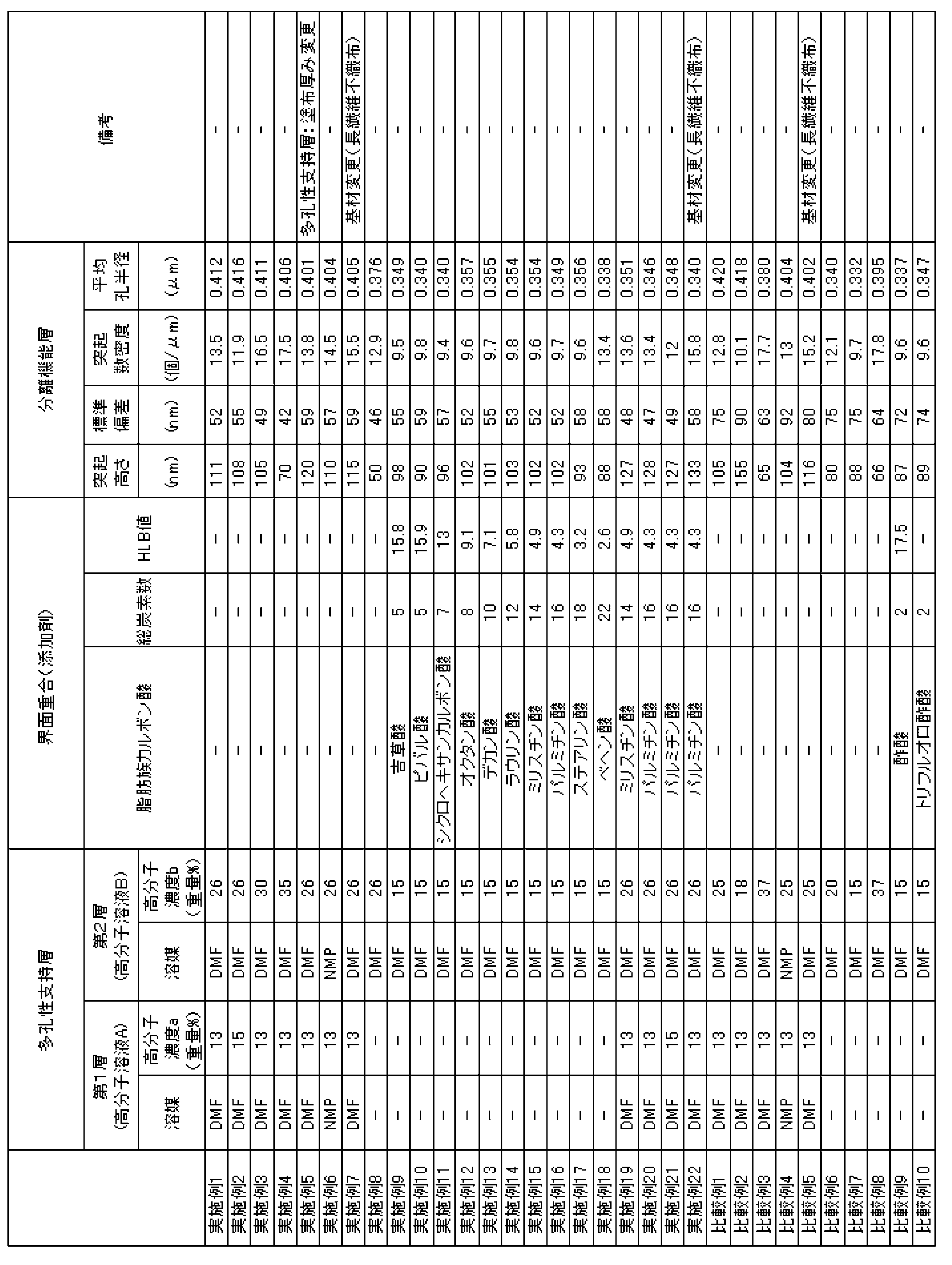
- Example 1 Polysulfone as a solute and DMF as a solvent are mixed, and heated and held at 90 ° C. for 2 hours with stirring, so that a polysulfone 13 wt% DMF solution (polymer solution A) and polysulfone 26 wt% DMF solution (high Molecular solutions B) were prepared respectively.
- the prepared polymer solutions A and B were each cooled to room temperature, supplied to separate extruders, and subjected to high-precision filtration. Thereafter, the filtered polymer solution was passed through a double slit die, and a short fiber nonwoven fabric obtained from a polyethylene terephthalate fiber by a papermaking method (thread diameter: 1 dtex, thickness: 90 ⁇ m, air permeability: 0.9 mL / cm 2 / sec.
- the polymer solution A was cast at a thickness of 110 ⁇ m and the polymer solution B was simultaneously cast at a thickness of 90 ⁇ m, and immediately immersed in pure water and washed for 5 minutes to obtain a support membrane.
- the obtained support membrane was immersed in a 4.0 wt% aqueous solution of m-PDA for 2 minutes, and then slowly lifted so that the membrane surface was vertical. Nitrogen was blown from the air nozzle to remove excess aqueous solution from the surface of the support membrane, and then an n-decane solution containing 0.12% by weight of trimesic acid chloride at 25 ° C. was applied so that the membrane surface was completely wetted. After leaving still for 1 minute, in order to remove excess solution from the film, the film surface was held vertically for 1 minute to drain the liquid. Then, the composite semipermeable membrane provided with a base material, a porous support layer, and a polyamide separation functional layer was obtained by washing with water at 45 ° C. for 2 minutes.
- Example 2 A composite semipermeable membrane in Example 2 was obtained in the same manner as in Example 1 except that a 15% by weight polysulfone DMF solution was prepared as the polymer solution A in Example 1.
- Example 3 A composite semipermeable membrane in Example 3 was obtained in the same manner as in Example 1 except that a DMF solution containing 30% by weight of polysulfone was prepared as the polymer solution B in Example 1.
- Example 4 A composite semipermeable membrane in Example 4 was obtained in the same manner as in Example 1 except that a DMF solution containing 35% by weight of polysulfone was prepared as the polymer solution B in Example 1.
- Example 5 In Example 1, the composite semipermeable membrane in Example 5 was obtained in the same manner as in Example 1 except that the film thickness to be cast was changed to 150 ⁇ m for the polymer solution A and 50 ⁇ m for the polymer solution B.
- Example 6 The composite in Example 6 was prepared in the same manner as in Example 1 except that an NMP solution containing 13% by weight of polysulfone was prepared as the polymer solution A and an NMP solution containing 26% by weight of polysulfone was prepared as the polymer solution B. A semipermeable membrane was obtained.
- Example 7 In Example 1, a non-woven fabric made of polyethylene terephthalate fibers as a substrate on which a polymer solution is applied (thread diameter: 1 dtex, thickness: about 90 ⁇ m, air permeability: 1.3 mL / cm 2 / sec, porous support layer
- the semi-transparent composite in Example 7 was used in the same manner as in Example 1 except that the fiber orientation degree of the side surface layer: 40 ° and the fiber orientation degree of the surface layer opposite to the porous support layer: 20 °. A membrane was obtained.
- Example 8 Example 1 except that polymer solution A was not used, and only 26% by weight of polysulfone DMF solution as polymer solution B was applied to the nonwoven fabric with a thickness of 200 ⁇ m using a single slit die instead of a double slit die. In the same manner as in Example 1, a composite semipermeable membrane in Example 8 was obtained.
- Example 9 In Example 8, a support membrane obtained using a DMF solution containing 15% by weight of polysulfone was immersed in an aqueous amine solution containing 1.8% by mass of m-PDA for 2 minutes, and then slowly so that the membrane surface was vertical. And raised it. Nitrogen was blown from the air nozzle to remove excess aqueous solution from the surface of the support membrane, and then an n-decane solution at 25 ° C. containing 0.12% by mass of trimesic acid chloride and 0.12% by mass of valeric acid as an aliphatic carboxylic acid was obtained. It was applied so that the film surface was completely wetted.
- Example 9 After leaving still for 1 minute, in order to remove excess solution from the film, the film surface was held vertically for 1 minute to drain the liquid. Then, the composite semipermeable membrane in Example 9 provided with a base material, a porous support layer, and a polyamide separation functional layer was obtained by washing with hot water at 90 ° C. for 2 minutes.
- Example 10 to 18 Composite semipermeable membranes in Examples 10 to 18 were obtained in the same manner as in Example 9 except that the aliphatic carboxylic acid shown in Table 1 was used instead of valeric acid in Example 9.
- Example 19 In the same manner as in Example 1 except that 0.12% by mass of myristic acid as an aliphatic carboxylic acid was mixed in an n-decane solution at 25 ° C. containing 0.12% by mass of trimesic acid chloride in Example 1. The composite semipermeable membrane in Example 19 was obtained.
- Example 20 A composite semipermeable membrane in Example 20 was obtained in the same manner as in Example 19 except that palmitic acid was used in place of myristic acid in Example 19.
- Example 21 In Example 20, a composite semipermeable membrane in Example 21 was obtained in the same manner as in Example 20, except that the support membrane in Example 2 was used.
- Example 22 In Example 20, a composite semipermeable membrane in Example 22 was obtained in the same manner as in Example 20 except that the support membrane in Example 7 was used.
- Comparative Example 1 A composite semipermeable membrane in Comparative Example 1 was obtained in the same manner as in Example 1 except that a 25% by weight polysulfone DMF solution was used as the polymer solution B.
- Comparative Example 2 A composite semipermeable membrane in Comparative Example 2 was obtained in the same manner as in Example 1 except that a DMF solution containing 18% by weight of polysulfone was used as the polymer solution B.
- Comparative Example 3 A composite semipermeable membrane in Comparative Example 3 was obtained in the same manner as in Example 1 except that a 37% by weight polysulfone DMF solution was used as the polymer solution B.
- Comparative Example 4 The composite semipermeable membrane in Comparative Example 4 was prepared in the same manner as in Example 1 except that the polymer solution A was a 13% by weight polysulfone NMP solution and the polymer solution B was a 25% polysulfone NMP solution. Obtained.
- Comparative Example 5 A composite semipermeable membrane in Comparative Example 5 was obtained in the same manner as in Example 1 except that a long-fiber nonwoven fabric was used as the substrate and a 25% by weight polysulfone DMF solution was used as the polymer solution B.
- Comparative Example 6 In the same manner as in Example 8 except that the polymer solution A was not used for forming the porous support layer, and only a 20% by weight polysulfone DMF solution was used as the polymer solution B, the composite semipermeable material in Comparative Example 6 was used. A membrane was obtained.
- Comparative Example 7 In the same manner as in Example 8 except that the polymer solution A was not used for forming the porous support layer, and only a 15% by weight DMF solution of polysulfone was used as the polymer solution B, the composite semipermeable material in Comparative Example 7 was used. A membrane was obtained.
- Comparative Example 8 In the same manner as in Example 8 except that the polymer solution A was not used for forming the porous support layer and only a 37% by weight polysulfone DMF solution was used as the polymer solution B, the composite semipermeable material in Comparative Example 8 was used. A membrane was obtained.
- Comparative Example 9 A composite semipermeable membrane in Comparative Example 9 was obtained in the same manner as in Example 9 except that acetic acid was used instead of valeric acid in Example 9.
- Comparative Example 10 A composite semipermeable membrane in Comparative Example 10 was obtained in the same manner as in Example 9 except that trifluoroacetic acid was used instead of valeric acid in Example 9.
- the height of all the protrusions in the cross-sectional photograph was measured on a scale with a portion having a height of 1/5 or more of the 10-point average surface roughness as a protrusion.
- the average height was calculated and its standard deviation was calculated.
- the number was counted and the average number density of protrusions of the separation functional layer was determined.
- a composite semipermeable membrane sample is dried at room temperature under reduced pressure, and a measurement sample cut into a 1.5 cm ⁇ 1.5 cm square in the film surface direction is used to measure a positron annihilation lifetime measuring device (for example, radiation) with a positron beam generator.
- a positron annihilation lifetime measuring device for example, radiation
- the details of the apparatus are described in Physics and Chemistry, Vol. 58, p603, Pergamon (2000).
- the average pore radius R was determined from the average life ⁇ of the fourth component obtained by the analysis.
- TDS removal rate Seawater and simulated seawater were supplied to the composite semipermeable membrane at a temperature of 25 ° C., a pH of 6.5, and an operating pressure of 5.5 MPa, and a water treatment operation (filtration treatment) was performed for 24 hours. Thereafter, operation was further performed for 30 minutes under the same conditions to obtain permeated water, and the TDS concentration of this permeated water was measured.
- TDS removal rate (%) 100 ⁇ ⁇ 1 ⁇ (TDS concentration in permeated water / TDS concentration in feed water) ⁇
- TDS concentration of the seawater as the supply water was 3.5% by weight.
- a 3.5 wt% NaCl aqueous solution was used as simulated sea water.
- the composite semipermeable membrane of the present invention can be suitably used particularly for brine or seawater desalination.
Landscapes
- Chemical & Material Sciences (AREA)
- Chemical Kinetics & Catalysis (AREA)
- Engineering & Computer Science (AREA)
- Water Supply & Treatment (AREA)
- Nanotechnology (AREA)
- Life Sciences & Earth Sciences (AREA)
- Hydrology & Water Resources (AREA)
- Environmental & Geological Engineering (AREA)
- Organic Chemistry (AREA)
- Separation Using Semi-Permeable Membranes (AREA)
Abstract
Description
そこで本発明の目的は、高い塩除去性、高い透水性を両立しながら、ファウリングに起因した性能低下が小さい複合半透膜および複合半透膜エレメントを安価かつ簡便に提供することにある。
<1> 基材および前記基材上に設けられた多孔性支持層を有する支持膜と、前記支持膜上に設けられた分離機能層とを備えた複合半透膜であって、電子顕微鏡を用いて前記複合半透膜の膜面方向における長さが2.0μmである任意の10箇所の断面を観察したときに、各断面において、前記分離機能層における10点平均面粗さの5分の1以上の高さを有する突起の高さの標準偏差が60nm以下である複合半透膜。
<2> 陽電子消滅寿命測定法により測定された、前記分離機能層中の平均孔半径が0.300nm以上、0.400nm以下である、前記<1>に記載の複合半透膜。
<3> 各断面における前記突起の平均高さが100nm以上、300nm以下である、前記<1>または<2>に記載の複合半透膜。
<4> 各断面における前記突起の平均数密度が10.0個/μm以上、30.0個/μm以下である、前記<1>~<3>のいずれか1に記載の複合半透膜。
<5> 前記多孔性支持層が、基材側の第1層とその上に形成される第2層の多層構造を有し、かつ前記第1層を形成する高分子溶液Aと前記第2層を形成する高分子溶液Bとが前記基材上に同時に塗布された後に、凝固浴に接触し相分離することで形成される、前記<1>~<4>のいずれか1に記載の複合半透膜。
<6> 前記高分子溶液Bの固形分濃度b(重量%)が、25重量%を超え、35重量%以下である、前記<5>に記載の複合半透膜。
<7> 前記高分子溶液Aの固形分濃度a(重量%)と前記高分子溶液Bの固形分濃度b(重量%)が、a/b<1.0の関係式を満たす、前記<6>に記載の複合半透膜。
<8> 前記支持膜の基材がポリエステルを含有する長繊維不織布である、前記<1>~<7>のいずれか1に記載の複合半透膜。
<9> 前記<1>~<8>のいずれか1に記載の複合半透膜が、原水流路材及び透過水流路材と共に、多数の孔を穿設した筒状の集水管の周りに巻回されている、スパイラル型複合半透膜エレメント。
複合半透膜は、基材および前記基材上に設けられた多孔性支持層を含む支持膜と、前記多孔性支持層上に設けられた分離機能層とを備える。
(1-1)分離機能層
分離機能層は、複合半透膜において溶質の分離機能を担う層である。分離機能層の組成および厚み等の構成は、複合半透膜の使用目的に合わせて設定される。
上述したように、従来の膜は使用によって性能が低下することがある。これに対して、本発明者らは、鋭意検討の結果、ひだ構造を備える分離機能層において、そのひだ(突起)の高さの標準偏差が60nm以下であると、複合半透膜の性能の低下が抑制されることを見いだした。これは、突起の高さが均一化されることで、有機物およびコロイド等のファウリング物質の堆積が抑制されるからであると考えられる。
なお、突起の高さの標準偏差は、電子顕微鏡を用いた10点平均面粗さの5分の1以上の高さを有する突起の高さの標準偏差の値を用いる。10点平均面粗さの測定方法については後述する。
10点平均面粗さとは、次のような算出方法で得られる値である。
まず電子顕微鏡により、膜面に垂直な方向の断面を下記の倍率で観察することで、断面画像を得る。得られた断面画像には、分離機能層(図1に符号“1”で示す。)の表面が、凸部と凹部が連続的に繰り返される、ひだ構造の曲線として表れる。断面画像における複合半透膜の膜面方向(膜の表面に平行な方向)に2.0μmの幅の領域について、この曲線に基づき、ISO4287:1997で定義される粗さ曲線を求める。
次に、上記粗さ曲線の平均線の方向に2.0μmの幅で断面画像を抜き取る(図1)。なお、平均線とは、ISO4287:1997に基づき定義される直線であり、測定長さにおいて、平均線と粗さ曲線とで囲まれる領域の面積の合計が平均線の上下で等しくなるように描かれる直線である。
抜き取った幅2.0μmの画像において、上記平均線を基準線として、分離機能層における突起の山頂の高さと、谷底の深さをそれぞれ測定する。最も高い山頂から5番目までの5つの山頂の高さH1~H5の絶対値について平均値を算出し、最も深い谷底から5番目まで5つの谷底の深さD1~D5の絶対値について平均値を算出して、さらに、得られた2つの平均値の絶対値の和を算出する。こうして得られた和が、10点平均面粗さである。なお、図1では、説明の便宜上、基準線を水平方向に平行に描いている。
それぞれの平均寿命はp-Psで125ps、o-Psで140psであるが、凝集状態の物質中でo-Psは自己が結合しているのとは別の電子と重なって、ピックオフ消滅と呼ばれる消滅を起こす確率が高くなる。その結果o-Psの平均寿命は数nsまで短くなる。絶縁材料中のo-Psの消滅は、o-Psが物質中の空孔壁に存在する電子と重なり合うことによるので、空孔が小さいほど消滅速度が速くなる。すなわちo-Psの消滅寿命は、絶縁材料中の空孔径に関連づけることができる。

支持膜は、基材と多孔性支持層とを備えるものであり、実質的にイオン等の分離性能を有さず、実質的に分離性能を有する分離機能層に強度を与えることができる。
多孔性支持層は、下記素材を主成分として含有することが好ましい。多孔性支持層の素材としては、ポリスルホン、ポリエーテルスルホン、ポリアミド、ポリエステル、セルロース系ポリマー、ビニルポリマー、ポリフェニレンスルフィド、ポリフェニレンスルフィドスルホン、ポリフェニレンスルホン、ポリフェニレンオキシドなどのホモポリマーあるいはコポリマーを単独であるいはブレンドして使用することができる。ここでセルロース系ポリマーとしては酢酸セルロース、硝酸セルロースなどが使用され、ビニルポリマーとしてはポリエチレン、ポリプロピレン、ポリ塩化ビニル、ポリアクリロニトリルなどが使用される。中でもポリスルホン、ポリアミド、ポリエステル、酢酸セルロース、硝酸セルロース、ポリ塩化ビニル、ポリアクリロニトリル、ポリフェニレンスルフィド、ポリフェニレンスルフィドスルホン、ポリフェニレンスルホンなどのホモポリマーまたはコポリマーが好ましい。より好ましくは酢酸セルロース、ポリスルホン、ポリフェニレンスルフィドスルホン、またはポリフェニレンスルホンが挙げられる。これらの素材の中では化学的、機械的、熱的に安定性が高く、成型が容易であることからポリスルホンが特に好ましくに使用できる。

そのような構造の例として、多孔性支持層は、多官能アミン水溶液を効率的に移送する第1層と、第1層よりも分離機能層寄りに位置し、突起の数密度を制御する第2層とを備えることが好ましい。特に、第1層は基材に接することが好ましく、第2層は分離機能層に接するように、多孔性支持層の最表層に位置することが好ましい。
なお、上記第1層と第2層は、いずれも高分子溶液を塗布することにより形成されるが、その製造方法については後述する。
支持膜を構成する基材としては、例えば、ポリエステル系重合体、ポリアミド系重合体、ポリオレフィン系重合体、あるいはこれらの混合物や共重合体等が挙げられるが、機械的強度、耐熱性、耐水性等により優れた支持膜を得られることから、ポリエステル系重合体であることが好ましい。これらは単独で用いても、複数種を同時に用いてもよい。
以上より、本発明における支持膜を構成する基材としては、ポリエステルを含む、長繊維不織布であることが好ましい。
次に、上記複合半透膜の製造方法について説明する。製造方法は、支持膜の形成工程および分離機能層の形成工程を含む。
支持膜の形成工程は、多孔性基材に高分子溶液を塗布する工程、多孔性基材に高分子溶液を含浸させる工程、および前記溶液を含浸した前記多孔性基材を、高分子の良溶媒と比較して前記高分子の溶解度が小さい凝固浴に浸漬させて前記高分子を凝固させ、三次元網目構造を形成させる工程を含んでもよい。また、支持膜の形成工程は、多孔性支持層の成分である高分子を、その高分子の良溶媒に溶解して高分子溶液を調製する工程を、さらに含んでいてもよい。
高分子溶液塗布時の高分子溶液の温度は、例えばポリスルホンであれば、通常10~60℃の範囲内が好ましい。この範囲内であれば、高分子溶液が析出することなく、高分子を含む有機溶媒溶液が基材の繊維間にまで充分含浸したのち固化される。その結果、アンカー効果により支持膜が基材に強固に接合し、本発明の支持膜を得ることができる。なお、高分子溶液の温度範囲は、用いる高分子溶液の粘度などによって適宜調整すればよい。
次に、複合半透膜を構成する分離機能層の形成工程の一例として、ポリアミドを主成分とする層(ポリアミド分離機能層)の形成を挙げて説明する。
ポリアミド分離機能層の形成工程は、前述の多官能アミンを含有する水溶液と、多官能酸ハロゲン化物を含有する水と非混和性の有機溶媒溶液とを用い、支持膜の表面で界面重縮合を行うことにより、ポリアミド骨格を形成することを含む。
支持膜と多官能アミン水溶液との接触時間は、5秒以上10分以下の範囲内であることが好ましく、10秒以上3分以下の範囲内であるとさらに好ましい。
液切りの方法としては、例えば、日本国特開平2-78428号公報に記載されているように、多官能アミン水溶液接触後の支持膜を垂直方向に把持して過剰の水溶液を自然流下させる方法や、エアーノズルから窒素などの気流を吹き付け、強制的に液切りする方法などが挙げられる。また、液切り後、膜面を乾燥させて水溶液の水分を一部除去することもできる。
HLB値=20×親水部のHLB値
=20×(親水部の式量の総和)/(分子量)
このようにして製造される複合半透膜は、プラスチックネットなどの原水流路材と、トリコットなどの透過水流路材と、必要に応じて耐圧性を高めるためのフィルムと共に、多数の孔を穿設した筒状の集水管の周りに巻回され、スパイラル型の複合半透膜エレメントを形成することができる。さらに、このエレメントは、直列または並列に接続されて圧力容器に収納されることで、複合半透膜モジュールを構成することもできる。
(実施例1)
溶質であるポリスルホンと溶媒であるDMFを混合し、攪拌しながら90℃で2時間加熱保持することで、ポリスルホン13重量%のDMF溶液(高分子溶液A)およびポリスルホン26重量%のDMF溶液(高分子溶液B)をそれぞれ調製した。
実施例1において、高分子溶液Aとしてポリスルホン15重量%のDMF溶液を調製した以外は、実施例1と同様にして、実施例2における複合半透膜を得た。
実施例1において、高分子溶液Bとしてポリスルホン30重量%のDMF溶液を調製した以外は、実施例1と同様にして、実施例3における複合半透膜を得た。
実施例1において、高分子溶液Bとしてポリスルホン35重量%のDMF溶液を調製した以外は、実施例1と同様にして、実施例4における複合半透膜を得た。
実施例1において、キャストする膜厚を、高分子溶液Aを150μm、高分子溶液Bを50μmに変更した以外は、実施例1と同様にして、実施例5における複合半透膜を得た。
実施例1において、高分子溶液Aとしてポリスルホン13重量%のNMP溶液を、高分子溶液Bとしてポリスルホン26重量%のNMP溶液を調製した以外は、実施例1と同様にして、実施例6における複合半透膜を得た。
実施例1において、高分子溶液を塗布する基材としてポリエチレンテレフタレート繊維からなる長繊維不織布(糸径:1デシテックス、厚み:約90μm、通気度:1.3mL/cm2/sec、多孔性支持層側表層の繊維配向度:40°、多孔性支持層とは反対側の表層での繊維配向度:20°)を用いた以外は、実施例1と同様にして、実施例7における複合半透膜を得た。
高分子溶液Aは用いず、高分子溶液Bとしてポリスルホン26重量%のDMF溶液のみを、二重スリットダイではなく単スリットダイを用いて、200μmの厚みで不織布上に塗布した以外は、実施例1と同様にして、実施例8における複合半透膜を得た。
実施例8において、ポリスルホン15重量%のDMF溶液を用いて得られた支持膜を、m-PDA1.8質量%を含むアミン水溶液中に2分間浸漬した後、膜面が鉛直になるようにゆっくりと引き上げた。エアーノズルから窒素を吹き付け支持膜表面から余分な水溶液を取り除いた後、トリメシン酸クロリド0.12質量%と脂肪族カルボン酸として吉草酸0.12質量%とを含む25℃のn-デカン溶液を膜表面が完全に濡れるように塗布した。1分間静置した後、膜から余分な溶液を除去するために膜面を1分間鉛直に保持して液切りした。その後、90℃の熱水で2分間洗浄することで、基材、多孔性支持層、およびポリアミド分離機能層を備える、実施例9における複合半透膜を得た。
実施例9の吉草酸に代えて、脂肪族カルボン酸として表1に示すものを用いた以外は、実施例9と同様にして、実施例10~18における複合半透膜を得た。
実施例1において、トリメシン酸クロリド0.12質量%を含む25℃のn-デカン溶液に脂肪族カルボン酸としてミリスチン酸0.12質量%を混合した以外は、実施例1と同様にして、実施例19における複合半透膜を得た。
実施例19のミリスチン酸に代えて、パルミチン酸を用いた以外は、実施例19と同様にして、実施例20における複合半透膜を得た。
実施例20において、実施例2の支持膜を用いた以外は、実施例20と同様にして、実施例21における複合半透膜を得た。
実施例20において、実施例7の支持膜を用いた以外は、実施例20と同様にして、実施例22における複合半透膜を得た。
高分子溶液Bとしてポリスルホン25重量%のDMF溶液を用いた以外は、実施例1と同様にして、比較例1における複合半透膜を得た。
高分子溶液Bとしてポリスルホン18重量%のDMF溶液を用いた以外は、実施例1と同様にして、比較例2における複合半透膜を得た。
高分子溶液Bとしてポリスルホン37重量%のDMF溶液を用いた以外は、実施例1と同様にして、比較例3における複合半透膜を得た。
高分子溶液Aとしてポリスルホン13重量%のNMP溶液を用い、高分子溶液Bとしてポリスルホン25重量%のNMP溶液を用いた以外は、実施例1と同様にして、比較例4における複合半透膜を得た。
基材として長繊維不織布を用い、かつ高分子溶液Bとしてポリスルホン25重量%のDMF溶液を用いた以外は、実施例1と同様にして、比較例5における複合半透膜を得た。
多孔性支持層の形成に、高分子溶液Aは用いず、高分子溶液Bとしてポリスルホン20重量%のDMF溶液のみを用いた以外は、実施例8と同様にして、比較例6における複合半透膜を得た。
多孔性支持層の形成に、高分子溶液Aは用いず、高分子溶液Bとしてポリスルホン15重量%のDMF溶液のみを用いた以外は、実施例8と同様にして、比較例7における複合半透膜を得た。
多孔性支持層の形成に、高分子溶液Aは用いず、高分子溶液Bとしてポリスルホン37重量%のDMF溶液のみを用いた以外は、実施例8と同様にして、比較例8における複合半透膜を得た。
実施例9の吉草酸に代えて、酢酸を用いた以外は、実施例9と同様にして、比較例9における複合半透膜を得た。
実施例9の吉草酸に代えて、トリフルオロ酢酸を用いた以外は、実施例9と同様にして、比較例10における複合半透膜を得た。
複合半透膜サンプルをエポキシ樹脂で包埋し、断面観察を容易にするためOsO4で染色して、これをウルトラミクロトームで切断し超薄切片を10個作製した。得られた超薄切片について、透過型電子顕微鏡を用いて断面写真を撮影した。観察時の加速電圧は100kVであり、観察倍率は10,000倍であった。
得られた断面写真について、スケールを用いて、支持膜の膜面方向の幅2.0μmの領域における突起の数を測定し、上述した方法で10点平均面粗さを算出した。この10点平均面粗さに基づいて、10点平均面粗さの5分の1以上の高さを有する部分を突起として、断面写真中の全ての突起の高さをスケールで測定し、突起の平均高さを求めると共に、その標準偏差を計算した。また、その数を数え、分離機能層の突起の平均数密度を求めた。
複合半透膜サンプルを、減圧下室温で乾燥させ、膜面方向に1.5cm×1.5cm角に切り取った測定試料を、陽電子ビーム発生装置を持つ薄膜対応陽電子消滅寿命測定装置(例えば、ラジエーション・フィジクス・アンド・ケミストリー、58巻、p603、パーガモン(2000)にその装置の詳細が述べられている。)にて、ビーム強度1keV、室温、真空下、光電子増倍管を使用して二フッ化バリウム製シンチレータを備えるシンチレーションカウンターにより総カウント数500万で測定し、POSITRONFITにて解析を行った。解析により得られた第4成分の平均寿命τから、平均孔半径Rを求めた。
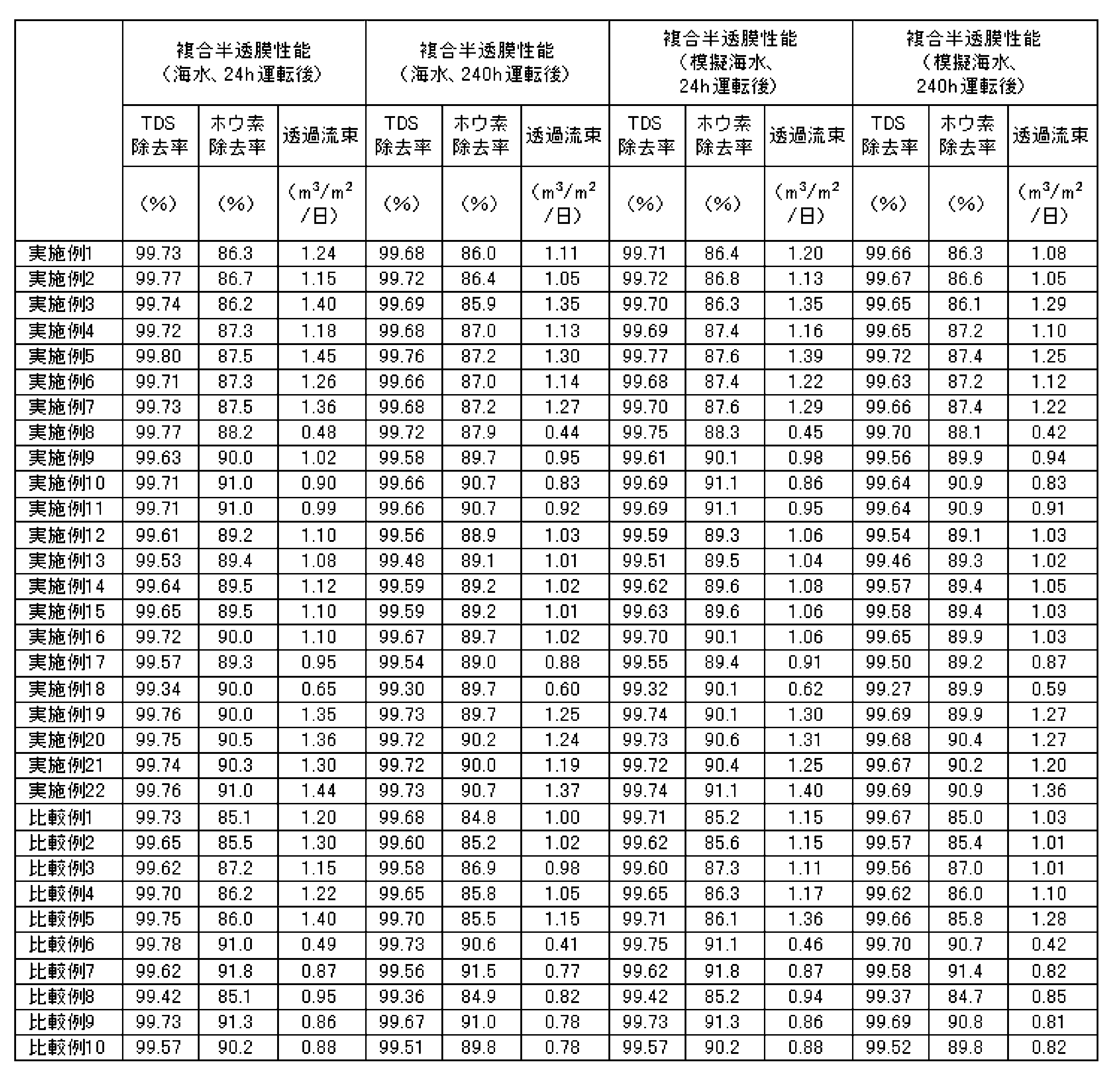
海水と模擬海水を温度25℃、pH6.5、操作圧力5.5MPaで複合半透膜に供給し、24時間に渡って水処理操作(ろ過処理)を行った。その後、さらに同条件で30分間操作を行って透過水を得て、この透過水のTDS濃度を測定した。
TDS除去率(%)=100×{1-(透過水中のTDS濃度/供給水中のTDS濃度)}
なお、供給水である海水のTDS濃度は3.5重量%であった。また、模擬海水としては3.5重量%のNaCl水溶液を用いた。
上記と同様に24時間ろ過処理を実施後、供給水と得られた透過水中のホウ素濃度をICP発光分析装置(日立製作所製のP-4010)で分析し、次の式からホウ素除去率を求めた。
ホウ素除去率=100×{1-(透過水中のホウ素濃度/供給水中のホウ素濃度)}
なお、供給水である海水のホウ素濃度は5ppmであった。
上記と同様に24時間ろ過処理を実施後、得られた透過水量を複合半透膜の面積から膜面1平方メートルあたり、1日あたりの透水量(立方メートル)に換算し、膜透過流束(m3/m2/日)として表した。
海水と模擬海水を温度25℃、pH6.5、操作圧力5.5MPaで複合半透膜に供給し、24時間後、240時間後のそれぞれのTDS除去率、膜透過流速の変化の比較から膜面の耐ファウリング性を確認した。高圧運転下では、圧力に起因した多孔質支持膜の変形による性能変化も伴うため、圧力の影響を切り離した比較ができるよう、海水と模擬海水による平行評価を実施した。なお、海水は一般的にファウリングしやすく、模擬海水は一般的にファウリングしにくい。
本出願は2012年6月27日出願の日本特許出願(特願2012-143918)及び2012年9月26日出願の日本特許出願(特願2012-212710)に基づくものであり、その内容はここに参照として取り込まれる。
H1~H5 分離機能層のひだ構造における突起の高さ
D1~D5 分離機能層のひだ構造における谷の深さ
Claims (9)
- 基材および前記基材上に設けられた多孔性支持層を有する支持膜と、前記支持膜上に設けられた分離機能層とを備えた複合半透膜であって、
電子顕微鏡を用いて前記複合半透膜の膜面方向における長さが2.0μmである任意の10箇所の断面を観察したときに、各断面において、前記分離機能層における10点平均面粗さの5分の1以上の高さを有する突起の高さの標準偏差が60nm以下である複合半透膜。 - 陽電子消滅寿命測定法により測定された、前記分離機能層中の平均孔半径が0.300nm以上、0.400nm以下である、請求項1に記載の複合半透膜。
- 各断面における前記突起の平均高さが100nm以上、300nm以下である、請求項1または2に記載の複合半透膜。
- 各断面における前記突起の平均数密度が10.0個/μm以上、30.0個/μm以下である、請求項1~3のいずれか1項に記載の複合半透膜。
- 前記多孔性支持層が、基材側の第1層とその上に形成される第2層の多層構造を有し、かつ前記第1層を形成する高分子溶液Aと前記第2層を形成する高分子溶液Bとが前記基材上に同時に塗布された後に、凝固浴に接触し相分離することで形成される、請求項1~4のいずれか1項に記載の複合半透膜。
- 前記高分子溶液Bの固形分濃度b(重量%)が、25重量%を超え、35重量%以下である、請求項5に記載の複合半透膜。
- 前記高分子溶液Aの固形分濃度a(重量%)と前記高分子溶液Bの固形分濃度b(重量%)が、a/b<1.0の関係式を満たす、請求項6に記載の複合半透膜。
- 前記支持膜の基材がポリエステルを含有する長繊維不織布である、請求項1~7のいずれか1項に記載の複合半透膜。
- 請求項1~8のいずれか1項に記載の複合半透膜が、原水流路材及び透過水流路材と共に、多数の孔を穿設した筒状の集水管の周りに巻回されている、スパイラル型複合半透膜エレメント。
Priority Applications (2)
| Application Number | Priority Date | Filing Date | Title |
|---|---|---|---|
| JP2013534115A JP6237233B2 (ja) | 2012-06-27 | 2013-06-27 | 複合半透膜および複合半透膜エレメント |
| US14/411,418 US20150283515A1 (en) | 2012-06-27 | 2013-06-27 | Composite semipermeable membrane and composite semipermeable membrane element |
Applications Claiming Priority (4)
| Application Number | Priority Date | Filing Date | Title |
|---|---|---|---|
| JP2012143918 | 2012-06-27 | ||
| JP2012-143918 | 2012-06-27 | ||
| JP2012-212710 | 2012-09-26 | ||
| JP2012212710 | 2012-09-26 |
Publications (1)
| Publication Number | Publication Date |
|---|---|
| WO2014003140A1 true WO2014003140A1 (ja) | 2014-01-03 |
Family
ID=49783275
Family Applications (1)
| Application Number | Title | Priority Date | Filing Date |
|---|---|---|---|
| PCT/JP2013/067717 Ceased WO2014003140A1 (ja) | 2012-06-27 | 2013-06-27 | 複合半透膜および複合半透膜エレメント |
Country Status (3)
| Country | Link |
|---|---|
| US (1) | US20150283515A1 (ja) |
| JP (1) | JP6237233B2 (ja) |
| WO (1) | WO2014003140A1 (ja) |
Cited By (2)
| Publication number | Priority date | Publication date | Assignee | Title |
|---|---|---|---|---|
| JPWO2018143297A1 (ja) * | 2017-01-31 | 2019-11-21 | 東レ株式会社 | 複合半透膜及び複合半透膜の製造方法 |
| WO2020218571A1 (ja) * | 2019-04-26 | 2020-10-29 | 東レ株式会社 | 透析液再生方法 |
Families Citing this family (3)
| Publication number | Priority date | Publication date | Assignee | Title |
|---|---|---|---|---|
| WO2019187640A1 (ja) * | 2018-03-30 | 2019-10-03 | 日本碍子株式会社 | ゼオライト膜複合体、ゼオライト膜複合体の製造方法、および、分離方法 |
| US20230041516A1 (en) * | 2019-12-27 | 2023-02-09 | Council Of Scientific & Industrial Research | Highly permeable ultrathin polymer nanofilm composite membrane and a process for preparation thereof |
| US12186711B2 (en) * | 2021-04-22 | 2025-01-07 | Toray Industries, Inc. | Composite semipermeable membrane |
Citations (5)
| Publication number | Priority date | Publication date | Assignee | Title |
|---|---|---|---|---|
| JPH09225273A (ja) * | 1996-02-23 | 1997-09-02 | Nitto Denko Corp | 積層非対称膜及びその製造方法 |
| JP2000202257A (ja) * | 1999-01-14 | 2000-07-25 | Toray Ind Inc | 複合半透膜およびその製造方法 |
| JP2001038155A (ja) * | 1999-08-03 | 2001-02-13 | Toray Ind Inc | 有機液体混合物用分離膜 |
| JP2006142275A (ja) * | 2004-10-21 | 2006-06-08 | Matsushita Electric Ind Co Ltd | 酸素透過膜、酸素透過シート、およびこれらを含む電池 |
| JP2011005455A (ja) * | 2009-06-29 | 2011-01-13 | Toray Ind Inc | 分離膜支持体並びにそれを用いた分離膜および膜分離エレメント |
Family Cites Families (3)
| Publication number | Priority date | Publication date | Assignee | Title |
|---|---|---|---|---|
| JPH0810595A (ja) * | 1994-06-29 | 1996-01-16 | Nitto Denko Corp | 複合逆浸透膜 |
| NL1030346C2 (nl) * | 2004-11-15 | 2006-09-20 | Toray Industries | Semipermeabel composietmembraan, productiewerkwijze daarvan, en element, fluïdumscheidingsinstallatie en werkwijze voor behandeling van water onder toepassing van hetzelfde. |
| JP2008535648A (ja) * | 2005-03-09 | 2008-09-04 | ザ リージェンツ オブ ザ ユニバーシティ オブ カリフォルニア | ナノ複合膜ならびにそれを作製および使用する方法 |
-
2013
- 2013-06-27 US US14/411,418 patent/US20150283515A1/en not_active Abandoned
- 2013-06-27 WO PCT/JP2013/067717 patent/WO2014003140A1/ja not_active Ceased
- 2013-06-27 JP JP2013534115A patent/JP6237233B2/ja active Active
Patent Citations (5)
| Publication number | Priority date | Publication date | Assignee | Title |
|---|---|---|---|---|
| JPH09225273A (ja) * | 1996-02-23 | 1997-09-02 | Nitto Denko Corp | 積層非対称膜及びその製造方法 |
| JP2000202257A (ja) * | 1999-01-14 | 2000-07-25 | Toray Ind Inc | 複合半透膜およびその製造方法 |
| JP2001038155A (ja) * | 1999-08-03 | 2001-02-13 | Toray Ind Inc | 有機液体混合物用分離膜 |
| JP2006142275A (ja) * | 2004-10-21 | 2006-06-08 | Matsushita Electric Ind Co Ltd | 酸素透過膜、酸素透過シート、およびこれらを含む電池 |
| JP2011005455A (ja) * | 2009-06-29 | 2011-01-13 | Toray Ind Inc | 分離膜支持体並びにそれを用いた分離膜および膜分離エレメント |
Cited By (5)
| Publication number | Priority date | Publication date | Assignee | Title |
|---|---|---|---|---|
| JPWO2018143297A1 (ja) * | 2017-01-31 | 2019-11-21 | 東レ株式会社 | 複合半透膜及び複合半透膜の製造方法 |
| JP7115308B2 (ja) | 2017-01-31 | 2022-08-09 | 東レ株式会社 | 複合半透膜及び複合半透膜の製造方法 |
| WO2020218571A1 (ja) * | 2019-04-26 | 2020-10-29 | 東レ株式会社 | 透析液再生方法 |
| JP6795126B1 (ja) * | 2019-04-26 | 2020-12-02 | 東レ株式会社 | 透析液再生方法 |
| EP3960218A4 (en) * | 2019-04-26 | 2023-01-11 | Toray Industries, Inc. | PROCEDURE FOR REGENERATION OF A DIALYSIS SOLUTION |
Also Published As
| Publication number | Publication date |
|---|---|
| JPWO2014003140A1 (ja) | 2016-06-02 |
| US20150283515A1 (en) | 2015-10-08 |
| JP6237233B2 (ja) | 2017-11-29 |
Similar Documents
| Publication | Publication Date | Title |
|---|---|---|
| JP6146303B2 (ja) | 複合半透膜およびその製造方法 | |
| JP6052172B2 (ja) | 複合半透膜の製造方法 | |
| JP6197649B2 (ja) | 複合半透膜 | |
| KR101985351B1 (ko) | 복합 반투막, 복합 반투막 엘리먼트 및 복합 반투막의 제조 방법 | |
| JP6237232B2 (ja) | 複合半透膜 | |
| JP2018039003A (ja) | 複合半透膜およびその製造方法 | |
| JP2019098330A (ja) | 複合半透膜およびその製造方法 | |
| JP6237233B2 (ja) | 複合半透膜および複合半透膜エレメント | |
| JPWO2014133133A1 (ja) | 複合半透膜 | |
| JP2014065004A (ja) | 複合半透膜 | |
| JP2014065003A (ja) | 複合半透膜及びその膜を用いた造水方法 | |
| WO2017057378A1 (ja) | 複合半透膜 | |
| JP2014188407A (ja) | 複合半透膜 | |
| WO2014208603A1 (ja) | 複合分離膜および分離膜エレメント | |
| JP2014064989A (ja) | 複合半透膜 | |
| JP2014151241A (ja) | 複合半透膜およびその製造方法 |
Legal Events
| Date | Code | Title | Description |
|---|---|---|---|
| ENP | Entry into the national phase |
Ref document number: 2013534115 Country of ref document: JP Kind code of ref document: A |
|
| 121 | Ep: the epo has been informed by wipo that ep was designated in this application |
Ref document number: 13810301 Country of ref document: EP Kind code of ref document: A1 |
|
| WWE | Wipo information: entry into national phase |
Ref document number: 14411418 Country of ref document: US |
|
| NENP | Non-entry into the national phase |
Ref country code: DE |
|
| 122 | Ep: pct application non-entry in european phase |
Ref document number: 13810301 Country of ref document: EP Kind code of ref document: A1 |