WO2014002869A1 - 発泡樹脂の成型方法、発泡樹脂成型体、発泡樹脂箱体、冷蔵庫、及び発泡樹脂の成型装置 - Google Patents
発泡樹脂の成型方法、発泡樹脂成型体、発泡樹脂箱体、冷蔵庫、及び発泡樹脂の成型装置 Download PDFInfo
- Publication number
- WO2014002869A1 WO2014002869A1 PCT/JP2013/066966 JP2013066966W WO2014002869A1 WO 2014002869 A1 WO2014002869 A1 WO 2014002869A1 JP 2013066966 W JP2013066966 W JP 2013066966W WO 2014002869 A1 WO2014002869 A1 WO 2014002869A1
- Authority
- WO
- WIPO (PCT)
- Prior art keywords
- foamed resin
- mold
- molding
- foamed
- molded
- Prior art date
- Legal status (The legal status is an assumption and is not a legal conclusion. Google has not performed a legal analysis and makes no representation as to the accuracy of the status listed.)
- Ceased
Links
Images



Classifications
-
- B—PERFORMING OPERATIONS; TRANSPORTING
- B29—WORKING OF PLASTICS; WORKING OF SUBSTANCES IN A PLASTIC STATE IN GENERAL
- B29C—SHAPING OR JOINING OF PLASTICS; SHAPING OF MATERIAL IN A PLASTIC STATE, NOT OTHERWISE PROVIDED FOR; AFTER-TREATMENT OF THE SHAPED PRODUCTS, e.g. REPAIRING
- B29C44/00—Shaping by internal pressure generated in the material, e.g. swelling or foaming ; Producing porous or cellular expanded plastics articles
- B29C44/02—Shaping by internal pressure generated in the material, e.g. swelling or foaming ; Producing porous or cellular expanded plastics articles for articles of definite length, i.e. discrete articles
- B29C44/04—Shaping by internal pressure generated in the material, e.g. swelling or foaming ; Producing porous or cellular expanded plastics articles for articles of definite length, i.e. discrete articles consisting of at least two parts of chemically or physically different materials, e.g. having different densities
- B29C44/0446—Shaping by internal pressure generated in the material, e.g. swelling or foaming ; Producing porous or cellular expanded plastics articles for articles of definite length, i.e. discrete articles consisting of at least two parts of chemically or physically different materials, e.g. having different densities by increasing the density locally by compressing part of the foam while still in the mould
-
- F—MECHANICAL ENGINEERING; LIGHTING; HEATING; WEAPONS; BLASTING
- F25—REFRIGERATION OR COOLING; COMBINED HEATING AND REFRIGERATION SYSTEMS; HEAT PUMP SYSTEMS; MANUFACTURE OR STORAGE OF ICE; LIQUEFACTION SOLIDIFICATION OF GASES
- F25D—REFRIGERATORS; COLD ROOMS; ICE-BOXES; COOLING OR FREEZING APPARATUS NOT OTHERWISE PROVIDED FOR
- F25D23/00—General constructional features
- F25D23/06—Walls
- F25D23/062—Walls defining a cabinet
- F25D23/064—Walls defining a cabinet formed by moulding, e.g. moulding in situ
Definitions
- the present invention relates to a method for molding a foamed resin, and in particular, a method for molding a foamed resin by thermoforming the surface of the foamed resin using a mold, a molded foamed resin molded body, a foamed resin box, and a foamed resin box
- the present invention relates to a refrigerator including a body and a foamed resin molding apparatus.
- Foamed resin is lightweight and has excellent heat insulation and buffering properties, and is widely used in various applications such as heat insulating materials and packing materials. However, while the foamed resin is lightweight, it has low strength and has a problem that the surface is rough and the appearance is impaired.
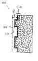
- Patent Document 1 Japanese Patent Laid-Open No. 9-174695 discloses a foamed plastic molded body 102 having a hard layer 101 on the surface as shown in FIG.
- the foamed plastic molded body 102 presses a template having a predetermined shape heated by a heater against the surface 103 of the foamed plastic from the left side to defoam the surface layer of the foamed plastic by a predetermined amount D.
- a predetermined amount D Manufactured by lowering the temperature below the softening point.
- the template is pressed against the surface 103 of the foamed plastic by a hydraulic cylinder, and the predetermined amount D represents the stroke amount of the hydraulic cylinder.
- the predetermined amount D is determined by the expansion ratio of the foamed resin to be used, the thickness D101 of the hard layer 101 to be molded, and the like.
- Patent Document 1 since the heated mold plate has heat after molding, the mold plate temperature is lower than the softening point of the foamed plastic even after defoaming by a predetermined amount D. The defoaming of the surface layer of the foamed plastic proceeds. As a result, the surface of foamed plastic is defoamed more than the stroke of the hydraulic cylinder, that is, the distance traveled by the template, so that the corners are rounded or the surface is not flat. There arises a problem that a gap is generated between them.
- Patent Document 1 bubbles generated by defoaming of the foamed plastic remain on the surface, and when the defoamed foamed plastic becomes the hard layer 101, a phenomenon of bubble biting in which bubbles remain in the hard layer 101 occurs. When this bubble biting occurs, there are fine dents in the hard layer 101, and a smooth surface as usual cannot be obtained.
- Patent Document 1 has a problem that the hard layer 101 having a desired shape cannot be accurately molded on the surface of the foamed plastic.
- the present invention has been made to solve the above-mentioned problems, and an object of the present invention is to provide a foamed resin molding method capable of accurately molding a hard layer having a desired shape on the surface of the foamed resin. is there.
- the foamed resin molding method of the present invention is a foamed resin molding method for molding the surface of the foamed resin using a mold, and includes a step of heating the mold, It includes a step of pressing against the foamed resin and defoaming the surface of the foamed resin while applying pressure, a step of cooling the foamed resin while applying pressure, and a step of removing the mold from the foamed resin.
- the foamed resin may further include a step of lowering the pressure applied to the foamed resin than when the foamed resin surface is defoamed before cooling the foamed resin.
- a hard layer having a desired shape can be accurately molded on the surface of the foamed resin.
- FIGS. 5A and 5B are views for explaining molding of the side surface of the inner box according to the second embodiment.
- FIGS. 6A and 6B are views for explaining molding of the upper surface and the lower surface of the inner box according to the second embodiment.
- FIGS. 7A and 7B are views for explaining molding of the inner surface of the inner box according to the second embodiment. It is a perspective view of the metal mold
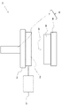
- FIG. 1 is a schematic view for explaining the molding apparatus of the first embodiment.
- the molding apparatus 1 includes a mold 2, a heating unit 3, a pressure unit 4, and a cooling unit 5.
- the mold 2 is heated by the heating unit 3.
- the pressure unit 4 includes a drive unit 7 and a support unit 8, and presses the mold 2 against the foamed resin to apply pressure to the foamed resin 6.
- the cooling unit 5 cools the foamed resin 6 by cooling the mold 2.
- the molding apparatus 1 presses the mold 2 heated by the heating unit 3 against the foamed resin 6 and defoams the surface layer of the foamed resin 6 while applying pressure to the foamed resin 6 by the pressurizing unit 4. Thereafter, the molding apparatus 1 cools the foamed resin 6 by the cooling unit 5, releases the pressure by the pressurizing unit 4, and removes the mold 2 from the foamed resin 6.
- the mold 2 is a molding means for molding the foamed resin 6, and the surface pressed against the foamed resin 6 may be a flat surface or may have irregularities.
- the thickness of the mold 2 is set to 36 mm or more so as not to be distorted even when pressure is applied.
- the thickness of the mold 2 can be changed according to the strength of the mold 2 and the amount of heat retention.
- die 2 may be comprised from one member, it may be comprised from the some member.
- the heating unit 3 is a heating means for heating the mold 2 and is, for example, a plate-shaped heater.
- the heating unit 3 may be a cartridge heater or the like that is inserted into the mold 2 to heat the mold 2, or may be configured to supply a high-temperature liquid to the mold 2.
- the pressurizing unit 4 is a pressurizing unit that applies pressure to the foamed resin 6 and includes a drive unit 7 and a support unit 8. That is, the pressurizing unit 4 moves the mold 2 in the direction of the arrow 9 by the driving unit 7, presses the mold 2 against the foamed resin 6 supported by the support unit 7, and foams with the mold 2 and the support unit 7. Pressure is applied to the foamed resin 6 by sandwiching the resin 6.
- the cooling unit 5 is a cooling means for cooling the foamed resin 6.
- the cooling unit 5 is configured to indirectly cool the foamed resin 6 by cooling the mold 2, and includes a pump that supplies a cooling liquid to the mold 2.
- the cooling unit 5 may be configured to directly cool the foamed resin 6, for example, may be configured to supply a cooling liquid to the foamed resin 6.
- FIG. 2 is a schematic view for explaining the foamed resin 6 molded by the molding apparatus 1.
- the foamed resin 6 molded by the molding apparatus 1 includes a foamed layer 6a and a hard layer 6b.
- the foamed resin 6 before being molded by the molding apparatus 1 is composed only of the foamed layer 6a, a part of the foamed layer 6a is defoamed by heat, and the defoamed part is cooled to cool the hard layer 6b.
- the hard layer 6b has a lower expansion ratio and higher hardness than the foam layer 6a, the strength of the foam resin 6 is increased by being molded by the molding apparatus 1.
- the hard layer 6b is shape
- the foamed resin 6 larger than the desired size is used in order to be molded into the desired size.
- the foamed resin 6 bead foamed polypropylene, bead foamed polyethylene, or the like is used.
- FIG. 3 is a flowchart for explaining a method of molding a foamed resin by the molding apparatus 1.
- step is represented by “S”, and each process is distinguished by a number.
- the molding apparatus 1 heats the mold 2 by the heating unit 3 (S1).
- the mold 2 is heated to 220 degrees.
- the mold 2 heated by the pressurizing unit 4 is pressed against the foamed resin 6 and pressurized (S2).
- a pressure of 0.2 kg / cm 2 is applied to the foamed resin 6.
- the foamed resin 6 is heated and defoamed in the vicinity of the portion in contact with the mold 2 by being pressed against the mold 2 heated to a high temperature.
- foaming is performed while applying pressure to the foamed resin 6, air bubbles generated by the foaming of the foamed resin 6 can be removed so as not to remain on the surface.
- the foamed resin 6 When the foamed resin 6 is close to a desired size, the foamed resin 6 is cooled by the cooling unit 5 while applying pressure to the foamed resin 6 (S3).
- the foamed resin 6 against which the mold 2 is pressed is cooled by setting the mold 2 to 100 degrees or less.
- the defoamed portion is formed as the hard layer 6b. Since the foamed resin 6 continues to be defoamed until it is sufficiently cooled, the foamed resin 6 has a desired dimension.
- the pressure unit 4 and the cooling unit 5 are controlled so that the cooling is completed. Thereafter, the pressure applied to the foamed resin 6 is released (S4), the mold 2 is removed from the foamed resin 6 in which the hard layer 6b is molded (S5), and the process ends.
- the pressure applied to the foamed resin 6 by the pressurizing unit 4 may be reduced before the foamed resin 6 is cooled in S3 or simultaneously with the start of the cooling.
- the pressure may be reduced to 0.05 kg / cm 2 .
- the foamed resin 6 continues to be defoamed until the foamed resin 6 is sufficiently cooled. There may be a gap between the two. That is, the hard layer 6b having a desired shape may not be accurately molded on the surface of the foamed resin 6. In addition, the hard layer 6b may be molded in a state where bubbles generated by defoaming remain on the surface, and foam biting may occur in the hard layer 6b.
- the hard layer 6b can be accurately molded without causing a gap between the foamed resin 6 and the mold 2, and when cooling is performed. It is possible to prevent the occurrence of bubble chewing by removing bubbles generated at the same time.
- the mold 2 is moved by the drive unit 7 and the mold 2 is pressed against the foamed resin 6 supported by the support unit 8.
- the present invention is not limited to this.
- the configuration may be such that the foamed resin 6 is moved by the drive unit 7 and pressed against the mold 2 supported by the support unit 8.
- the foamed resin 6 is defoamed and cooled in a state where the mold 2 is pressed against the foamed resin 6 and pressed, so that the hard layer 6b having a desired shape is formed on the surface of the foamed resin 6. Therefore, the foamed resin 6 having high strength and excellent design can be produced.
- the foamed resin 6 also has excellent heat insulation and buffering properties, the foamed resin 6 can be used as a heat insulating material and buffer material with excellent strength and design, for example, as a cooler box or a helmet. can do.
- FIG. 4 is a schematic view for explaining a refrigerator using the foamed resin of the present embodiment.
- the doors of the refrigerator, refrigeration cycle components such as an evaporator and a compressor, and electrical components such as a control board are not shown.
- the refrigerator 21 includes an inner box 22, an outer box 23, and a heat insulation board 24. Further, a shelf 25 for placing food and the like is provided inside the refrigerator 21, and a shelf receiving portion 26 for supporting the shelf 25 is molded in the inner box 22.
- the inner box 22 is a hollow rectangular parallelepiped box that is open on one side, and is a foamed resin box that is made of foamed resin and whose inner surface is thermoformed by the method of FIG. When thermoforming, by using a mold having projections and depressions for forming the shelf receiving portion 26, the shelf receiving portion 26 can also be formed, and the inner surface of the inner box 22 including the surface of the shelf receiving portion 26 A hard layer is molded throughout. Therefore, the inner surface of the inner box 22 has excellent aesthetics and strength.
- the outer box 23 forms the outermost shell of the refrigerator and has a role of maintaining the strength of the refrigerator 21, and here is a bent product of an iron plate.
- the heat insulation board 24 is disposed between the inner box 22 and the outer box 23 in order to give the refrigerator 21 sufficient heat insulation properties, and is made of foamed urethane or the like.
- the refrigerator 21 provided with the two inner boxes 22 is illustrated, not only this but the inner box 22 may be one and three or more may be sufficient.
- the inner surface of the inner box 22 is molded by the molding device 31.
- the molding apparatus 31 includes a plurality of molds 32a, 32b, 32c, and 32d and a drive unit 33 that drives the plurality of molds 32a, 32b, 32c, and 32d and presses them against the inner surface of the inner box 22.
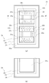
- FIG. 5 is a view for explaining molding of the side surface 22a of the inner box 22, and FIG. 5 (a) shows a state in which the inner box 22, the outer box 23, and the heat insulation board 24 before molding are combined.
- 22 shows an outline viewed from the opening side
- FIG. 5B shows an outline of a cross section taken along the line II ′ of FIG. 5A.
- the side surface 22a is molded by the mold 32a.
- the mold 32a includes a cartridge heater (not shown) and can heat the mold 32a.
- a cooling oil passage is formed inside the mold 32a, and the mold 32a is cooled by circulating cooling oil inside the mold 32a by a pump (not shown). Can do.
- the molding apparatus 31 moves the mold 32a in the direction of the arrow 34a by the drive unit 33 and presses the mold 32a against the side surface 22a.
- An indicator member (not shown) is arranged outside the outer box 23 so as to be in contact with the outer surface of the outer box 23, and is sandwiched between the outer box 23 supported by the indicator member and the heat insulating board 24 and the mold 32a, so that the inner box A pressure is applied to 22.
- the molding method by the molding apparatus 31 is the same as that shown in FIG. 3. That is, the mold 32a is heated, the mold 32a is pressed against the side surface 22a, the foamed resin on the side surface 22a is defoamed, and the pressure is applied.
- the pressure is released and the mold 32a is removed.
- the hard layer having a shape corresponding to the mold 32a can be accurately formed on the side surface 22a, and foaming of the hard layer can also be prevented.
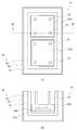
- FIG. 6 is a view for explaining molding of the upper surface 22b and the lower surface 22c of the inner box 22, and FIG. 6 (a) shows a state in which the inner box 22, the outer box 23, and the heat insulation board 24 before molding are combined. Is an outline as viewed from the opening side of the inner box 22, and FIG. 6 (b) is an outline of a cross section taken along the line II-II ′ of FIG. 6 (a). An instruction member (not shown) is disposed outside the outer box 23.
- the upper surface 22b is molded by the mold 32b, and the lower surface 22c is molded by the mold 32c.
- the molding device 31 moves the mold 32b in the direction of the arrow 34b by the drive unit 33 and presses it against the upper surface 22b, and moves the mold 32c in the direction of the arrow 34c and presses it against the lower surface 22c. Since the molding method of the upper surface 22b and the lower surface 22c by the molding apparatus 31 is the same as that of the side surface 22a, the description is omitted.
- FIG. 7 is a diagram for explaining the molding of the inner surface 22d of the inner box 22, and FIG. 7 (a) shows a state in which the inner box 22, the outer box 23, and the heat insulation board 24 before molding are combined.
- FIG. 7B shows an outline of the cross section taken along the line III-III ′ of FIG. 7A.
- An instruction member (not shown) is disposed outside the outer box 23.
- the back surface 22d is molded by a mold 32d.
- the molding apparatus 31 moves the mold 32d in the direction of the arrow 34d by the drive unit 33 and presses it against the back surface 22d. Since the molding method of the back surface 22d by the molding apparatus 31 is the same as that of the side surface 22a, the upper surface 22b, and the lower surface 22c, description thereof is omitted.
- FIG. 8 is a perspective view of the mold 32a and represents an example of the mold 32a. It is preferable to provide a shelf 25 for placing food or the like inside the inner box 22, and a shelf receiving portion 26 for supporting the shelf 25 is preferably formed on the side surface 22 a of the inner box 22. Therefore, it is preferable that the mold 32 a has a convex portion 35 for molding the shelf receiving portion 26. By using the mold 32a having the convex portion 35, a concave shelf receiving portion can be molded on the side surface 22a.
- the shape of the mold 32a is not limited to this.
- the mold 32a may have a concave portion for molding a convex shelf receiving portion on the side surface 22a.
- the shapes of the molds 32b, 32c, and 32d may be arbitrary shapes according to the shapes to be molded on the upper surface 22b, the lower surface 22c, and the back surface 22d, and may be flat or uneven.
- the inner box 22 can be manufactured by molding the inner surface for each surface, and the inner box 22 having high strength and excellent aesthetics can be manufactured by defoaming and cooling while applying pressure. it can.
- the shelf receiving part 26 for supporting the shelf 25 can also be simultaneously molded by using the mold 32a having irregularities.
- the molding of each surface of the inner box 22 may be performed on a plurality of surfaces simultaneously, but may be performed on each surface. In addition to the molding of each surface, the boundary or corner portion of each surface may be molded.
- the inner box 22 may be manufactured from one member, but may be manufactured by combining five plate-shaped foamed resins, and the surface of the five plate-shaped foamed resins is hardened. You may manufacture by combining after thermoforming.
- the present embodiment has a high strength and an excellent aesthetics by preventing the occurrence of foam biting by applying pressure to the inner surface of the foamed resin box while pressing the mold against the defoaming and cooling.
- a foamed resin box can be manufactured.
- the foamed resin box has a smooth surface, it is easy to remove dirt and can be suitably used as an inner box of a refrigerator.
- this embodiment demonstrated the refrigerator using the foamed resin molding which shape
Landscapes
- Engineering & Computer Science (AREA)
- Chemical & Material Sciences (AREA)
- Combustion & Propulsion (AREA)
- Physics & Mathematics (AREA)
- Mechanical Engineering (AREA)
- Thermal Sciences (AREA)
- General Engineering & Computer Science (AREA)
- Refrigerator Housings (AREA)
- Moulds For Moulding Plastics Or The Like (AREA)
Abstract
硬質層に気泡が残る泡噛みの発生を防止して発泡樹脂を成型する。金型を用いて発泡樹脂の表面を成型する発泡樹脂の成型方法であって、前記金型を加熱する工程と、前記金型を前記発泡樹脂に押し当て、圧力を加えながら前記発泡樹脂の表面を消泡する工程と、圧力を加えながら前記発泡樹脂を冷却する工程と、前記発泡樹脂から前記金型を取り外す工程を含む。
Description
本発明は、発泡樹脂の成型方法に関し、特に、金型を用いて発泡樹脂の表面を熱成型する発泡樹脂の成型方法、それによって成型された発泡樹脂成型体、発泡樹脂箱体、発泡樹脂箱体を備える冷蔵庫、及び発泡樹脂の成型装置に関する。
発泡樹脂は、軽量で、断熱性・緩衝性に優れた特性を有しており、断熱材や梱包材等の様々な用途に幅広く使用されている。しかし、発泡樹脂は、軽量である反面、強度は低く、また、表面が荒く美観を損ねるなどといった問題がある。
このような問題を解決するために、特許文献1(特開平9-174695号公報)では、図9に示すような表面に硬質層101を有する発泡プラスチック成形体102が開示されている。発泡プラスチック成形体102は、ヒータで加熱された所定形状を有する型板を左方より発泡プラスチックの表面103に押し当て、所定量Dだけ発泡プラスチックの表面層を消泡させ、その後、型板の温度を軟化点より低い温度まで低下させることで製造されている。型板は、油圧シリンダにより発泡プラスチックの表面103に押し当てられており、所定量Dは油圧シリンダのストローク量を表している。ここで、所定量Dは、用いる発泡樹脂の発泡倍率や、成形する硬質層101の厚さD101等によって定まる。
しかしながら、特許文献1は、加熱された型板が成形後も熱を持っているため、所定量Dだけ消泡させた後も、型板の温度が発泡プラスチックの軟化点より低い温度になるまで発泡プラスチックの表面層の消泡が進む。それにより、発泡プラスチックは、油圧シリンダのストローク量即ち型板の移動距離よりも多く表面が消泡されるため、角に丸みができたり表面が平坦にならなかったり、また型板と発泡プラスチックの間に間隙が生ずるという問題が発生する。
また、特許文献1は、発泡プラスチックの消泡により生じる気泡が表面に残り、消泡された発泡プラスチックが硬質層101になったときに硬質層101に気泡が残る泡噛みという現象が発生する。この泡噛みが生じると硬質層101に細かな凹みが存在することになり、型どおりの平滑な表面が得られないものとなる。
以上のように特許文献1には、発泡プラスチックの表面に所望する形状の硬質層101を正確に成型することができないという課題があった。
本発明は、上記課題を解決するためになされたものであり、その目的は、発泡樹脂の表面に所望する形状の硬質層を正確に成型することができる発泡樹脂の成型方法を提供することにある。
上記課題を解決するために、本発明の発泡樹脂の成型方法は、金型を用いて発泡樹脂の表面を成型する発泡樹脂の成型方法であって、金型を加熱する工程と、金型を発泡樹脂に押し当て、圧力を加えながら発泡樹脂の表面を消泡する工程と、圧力を加えながら発泡樹脂を冷却する工程と、発泡樹脂から金型を取り外す工程を含むことを特徴としている。
また、発泡樹脂の表面を消泡した後、発泡樹脂を冷却する以前に、発泡樹脂に加える圧力を発泡樹脂の表面を消泡したときよりも低くする工程をさらに含んでもよい。
本発明の発泡樹脂の成型方法によれば、発泡樹脂の表面に所望する形状の硬質層を正確に成型することができる。
(第一の実施形態)
以下、本発明の第一の実施形態について、図1から図3に基づいて説明する。なお、本明細書及び図面において、実質的に同一の機能構成を有する構成要素については、同一の符号を付して説明を省略している。
以下、本発明の第一の実施形態について、図1から図3に基づいて説明する。なお、本明細書及び図面において、実質的に同一の機能構成を有する構成要素については、同一の符号を付して説明を省略している。
図1は、第一の実施形態の成型装置を説明するための概略図である。成型装置1は、金型2と、加熱部3と、加圧部4と、冷却部5を備える。金型2は、加熱部3により加熱される。加圧部4は、駆動部7と支持部8からなり、金型2を発泡樹脂へ押し当て発泡樹脂6に圧力を加える。冷却部5は、金型2を冷却することで発泡樹脂6を冷却する。成型装置1は、加熱部3により加熱された金型2を発泡樹脂6へ押し当て、加圧部4により発泡樹脂6へ圧力を加えながら、発泡樹脂6の表層を消泡する。成型装置1は、その後、冷却部5により発泡樹脂6を冷却し、加圧部4による圧力を開放して、発泡樹脂6から金型2を取り外す。
金型2は、発泡樹脂6を成型する成型手段であり、発泡樹脂6に押し当てられる面は平面でもよく、凹凸を有していてもよい。また、金型2の厚さは、圧力が加えられても歪まないように、36mm以上としている。金型2の厚さは、金型2の強度及び保熱の量に応じて変えることができる。また、金型2は、1つの部材から構成されていてもよいが、複数の部材から構成されていてもよい。
加熱部3は、金型2を加熱する加熱手段であり、例えば、プレート状のヒータである。加熱部3は、金型2へ挿入して金型2を加熱するカートリッジヒータなどでもよく、金型2へ高温の液体を供給するような構成でもよい。
加圧部4は、発泡樹脂6へ圧力を加える加圧手段であり、駆動部7と支持部8を備える。即ち、加圧部4は、駆動部7により金型2を矢印9の方向へ動かし、支持部7で支えられた発泡樹脂6へ金型2を押し当て、金型2と支持部7で発泡樹脂6を挟むことにより発泡樹脂6へ圧力を加える。
冷却部5は、発泡樹脂6を冷却する冷却手段である。ここでは、冷却部5は金型2を冷却することで間接的に発泡樹脂6を冷却する構成であって、金型2へ冷却用の液体を供給するポンプを備えている。冷却部5は、発泡樹脂6を直接冷却するような構成でもよく、例えば、発泡樹脂6へ冷却用の液体を供給するような構成でもよい。
図2は、成型装置1で成型された発泡樹脂6を説明するための概略図である。成型装置1で成型された発泡樹脂6は、発泡層6aと硬質層6bから成る。成型装置1で成型される前の発泡樹脂6は、発泡層6aのみで構成され、発泡層6aの一部が熱により消泡し、この消泡した部分が冷却されることで硬質層6bとなる。硬質層6bは、発泡層6aよりも発泡倍率が低く、高い硬度を有するため、発泡樹脂6は成型装置1で成型されることで強度が高くなる。また、硬質層6bは、金型2が押し当てられた状態で成型されるため、硬質層6bへ金型2の表面の形状を転写させることができる。即ち、金型2の表面を任意の形状にすることで、所望の形状の硬質層6bを成型することができる。発泡樹脂6は、発泡層6aを有するため優れた緩衝性・断熱性を有するとともに、硬質層6bを有するため高い強度も有する。さらに、発泡樹脂6は、硬質層6bを任意の形状に成型することができるため、意匠的にも優れている。
発泡層6aは、消泡すると体積が小さくなるため、所望の大きさに成型するために、所望の大きさよりも大きい発泡樹脂6を用いる。具体的には、発泡樹脂6は、ビーズ発泡ポリプロピレン、ビーズ発泡ポリエチレンなどが用いられる。
図3は、成型装置1による発泡樹脂の成型方法を説明するためのフロー図である。なお、図3の説明においては、「ステップ」を「S」で表し、各工程を数字で区別している。
まず、成型装置1は、金型2を加熱部3により加熱する(S1)。ここでは、金型2を220度まで加熱する。次に、加圧部4により加熱された金型2を発泡樹脂6へ押し当て加圧する(S2)。ここでは、発泡樹脂6に0.2kg/cm2の圧力をかける。発泡樹脂6は、加熱され高温になった金型2を押し当てられることで、金型2と接触する部分の付近が加熱され消泡される。ここで、発泡樹脂6に圧力を加えながら消泡するため、発泡樹脂6の消泡により発生する気泡を表面に残さないように除くことができる。
発泡樹脂6が所望の寸法近傍になると、発泡樹脂6に圧力を加えながら冷却部5により発泡樹脂6を冷却する(S3)。ここでは、金型2を100度以下にすることで、金型2が押し当てられている発泡樹脂6を冷却する。発泡樹脂6が十分に冷却されることで、消泡された部分が硬質層6bとして成型されるが、十分に冷却されるまで発泡樹脂6の消泡が続くため、発泡樹脂6が所望の寸法になるときに冷却が完了するように加圧部4と冷却部5を制御する。その後、発泡樹脂6にかかる圧力を解放し(S4)、硬質層6bが成型された発泡樹脂6から金型2を取り外し(S5)、終了する。
S3で発泡樹脂6を冷却する前、又は冷却の開始と同時に、加圧部4によって発泡樹脂6に加えられる圧力を減圧してもよい。例えば、0.05kg/cm2の圧力に減圧してもよい。減圧してから冷却することで、発泡樹脂6を所望の寸法に合わせやすくなる。
ここで、仮に発泡樹脂6に加えられる圧力を0にしてから発泡樹脂6を冷却すると、発泡樹脂6が十分に冷却されるまで発泡樹脂6の消泡は続くため、発泡樹脂6と金型2の間に隙間ができる恐れがある。即ち、発泡樹脂6の表面に所望する形状の硬質層6bを正確に成型することができない場合がある。また、消泡により生じる気泡が表面に残った状態で硬質層6bが成型されてしまい、硬質層6bに泡噛みが発生する場合がある。S3で発泡樹脂6に圧力を加えながら発泡樹脂6を冷却することで、発泡樹脂6と金型2の間に隙間を生じさせず硬質層6bを正確に成型でき、また、冷却しているときに発生する気泡を除き泡噛みの発生を防止することができる。
本実施形態では、駆動部7により金型2を移動させて、金型2を支持部8に支えられる発泡樹脂6へ押し当てる構成としているが、これに限らない。駆動部7により発泡樹脂6を移動させて、発泡樹脂6を支持部8に支えられる金型2へ押し当てるような構成でもよい。
以上のように、本実施形態は、金型2を発泡樹脂6に押し当て加圧した状態で発泡樹脂6を消泡及び冷却することで、発泡樹脂6の表面に所望する形状の硬質層6bを正確に成型することができるため、高い強度と優れた意匠性を有する発泡樹脂6を製造することができる。また、発泡樹脂6は、優れた断熱性・緩衝性も有するため、発泡樹脂6を強度と意匠性が優れた断熱材・緩衝材として利用することができ、例えば、クーラーボックスや、ヘルメットとして利用することができる。
(第二の実施形態)
次に、本発明の第二の実施形態について図4から図8に基づいて説明する。図3の成型方法により成型された発泡樹脂は、高い強度と優れた美観を有しているため、冷蔵庫の内箱として利用することができる。
次に、本発明の第二の実施形態について図4から図8に基づいて説明する。図3の成型方法により成型された発泡樹脂は、高い強度と優れた美観を有しているため、冷蔵庫の内箱として利用することができる。
図4は、本実施形態の発泡樹脂を利用した冷蔵庫を説明するための概略図である。ただし、ここでは冷蔵庫の扉、蒸発器や圧縮機等の冷凍サイクル部品、及び制御基板等の電装部品は図示していない。
冷蔵庫21は、内箱22と、外箱23と、断熱ボード24を備える。また、冷蔵庫21内部には、食品などを載置するための棚25が設けられ、内箱22には、棚25を支えるための棚受け部26が成型されている。内箱22は、一面が開口する中空の直方体状の箱であり、発泡樹脂で構成され、内面が図3の方法により熱成型されている発泡樹脂箱体である。熱成型するときに、棚受け部26を成型するための凹凸を有した金型を用いることで、棚受け部26も成型することができ、棚受け部26の表面を含む内箱22の内面全体に硬質層が成型されている。そのため、内箱22の内面は、優れた美観と強度を有している。外箱23は、冷蔵庫の最外殻を形成するもので冷蔵庫21の強度を保つ役割があり、ここでは鉄板の曲げ加工品である。断熱ボード24は、冷蔵庫21に十分な断熱性を持たせるために、内箱22と外箱23の間に配置されるものであり、発泡ウレタンなどで構成される。ここでは、2つの内箱22を備える冷蔵庫21を図示しているが、これに限らず、内箱22は1つでもよく、3つ以上でもよい。また、棚25及び棚受け部26の数にも特に制限はなく、いくつ設けられていてもよい。
次に、冷蔵庫21の内箱22の内面の成型について、図5から図7を用いて説明する。内箱22の内面は、成型装置31によって成型される。成型装置31は、複数の金型32a、32b、32c、32dと、複数の金型32a、32b、32c、32dを駆動させ内箱22の内面に押し当てる駆動部33を備えている。
図5は、内箱22の側面22aの成型を説明するための図であり、図5(a)は、成型前の内箱22と外箱23と断熱ボード24が組み合わされた状態を内箱22の開口部側から見た概略を表しており、図5(b)は、図5(a)のI-I’線に沿った断面の概略を表している。側面22aは、金型32aにより成型される。金型32aは、図示しないカートリッジヒータを備えており、金型32aを加熱することができる。また、金型32aの内部には、冷却用のオイルの流路が形成されており、図示しないポンプにより冷却用のオイルを金型32aの内部で循環させることで、金型32aを冷却することができる。成型装置31は、駆動部33によって金型32aを矢印34aの方向へ動かし、側面22aへ押し当てる。外箱23の外側には、外箱23の外面に接するように図示しない指示部材が配置され、指示部材に支持された外箱23及び断熱ボード24と金型32aに挟まれることで、内箱22は圧力が加えられる。成型装置31による成型方法は、図3と同様であり、即ち、金型32aを加熱し、金型32aを側面22aへ押し当て圧力を加えながら側面22aの発泡樹脂を消泡し、圧力を加えながら金型32aを冷却し、圧力を解放して金型32aを取り外す。圧力を加えながら金型32aを冷却することで、側面22aに金型32aに対応する形状の硬質層を正確に成型することができ、硬質層の泡噛みも防止することができる。
図6は、内箱22の上面22b及び下面22cの成型を説明するための図であり、図6(a)は、成型前の内箱22と外箱23と断熱ボード24が組み合わされた状態を内箱22の開口部側から見た概略を表しており、図6(b)は、図6(a)のII-II’線に沿った断面の概略を表している。外箱23の外側には、図示しない指示部材が配置されている。上面22bは金型32bにより成型され、下面22cは、金型32cにより成型される。成型装置31は、駆動部33によって金型32bを矢印34bの方向へ動かし上面22bへ押し当て、金型32cを矢印34cの方向へ動かし下面22cへ押し当てる。成型装置31による上面22b及び下面22cの成型方法は、側面22aと同様であるため、説明を省略する。
図7は、内箱22の奥面22dの成型を説明するための図であり、図7(a)は、成型前の内箱22と外箱23と断熱ボード24が組み合わされた状態を内箱22の開口部側から見た概略を表しており、図7(b)は、図7(a)のIII-III’線に沿った断面の概略を表している。外箱23の外側には、図示しない指示部材が配置されている。奥面22dは金型32dにより成型される。成型装置31は、駆動部33によって金型32dを矢印34dの方向へ動かし、奥面22dへ押し当てる。成型装置31による奥面22dの成型方法は、側面22a、上面22b及び下面22cと同様であるため、説明を省略する。
図8は、金型32aの斜視図であり、金型32aの一例を表している。内箱22の内部には、食品などを載置するための棚25を設けることが好ましく、内箱22の側面22aには、棚25を支えるための棚受け部26を成型することが好ましい。そのため、金型32aは、棚受け部26を成型するための凸部35を有することが好ましい。凸部35を有する金型32aを用いることで、側面22aに凹状の棚受け部を成型することができる。金型32aの形状はこれに限らず、例えば、側面22aに凸状の棚受け部を成型するための凹部を有していてもよい。金型32b、32c、32dの形状は、上面22b、下面22c、奥面22dに成型する形状に合わせてそれぞれ任意の形状とすればよく、平面でもよく凹凸を有していてもよい。
以上のように、内面を各面毎に成型することで内箱22を製造でき、圧力を加えながら消泡及び冷却することで、高い強度と優れた美観を有する内箱22を製造することができる。このとき、凹凸を有する金型32aを用いることで、棚25を支えるための棚受け部26も同時に成型することができる。内箱22の各面の成型は、複数の面を同時に行ってもよいが、1つの面毎に行ってもよい。また、各面の成型とは別に、各面の境界やコーナーの部分の成型を行ってもよい。
本実施形態では、内箱22を外箱23及び断熱ボード24と組み合わせてから内箱22の内面を成型する例を説明したが、内箱22の内面を硬質に熱成型した後に内箱22を外箱23及び断熱ボード24と組み合わせてもよい。また、内箱22は、1つの部材から製造されていてもよいが、板状の発泡樹脂5枚を組み合わせることで製造されていてもよく、板状の発泡樹脂5枚の表面をそれぞれ硬質に熱成型してから組み合わせることで製造されていてもよい。
以上のように、本実施形態は、金型を発泡樹脂箱体の内面に押し当て圧力を加えながら消泡及び冷却することで、泡噛みの発生を防止して高い強度と優れた美観を有する発泡樹脂箱体を製造することができる。さらに、発泡樹脂箱体は、表面が滑らかになるため汚れも落ちやすく、冷蔵庫の内箱として好適に利用することができる。なお、本実施形態では、硬質層を成型された発泡樹脂成型体が用いられる冷蔵庫について説明したが、これに限らず、冷暖房器、空気清浄器やエアーコンディショナなどに用いることもできる。
本発明は、上述した各実施形態に限定されるものではなく、請求項に示した範囲で種々の変更が可能であり、異なる実施形態にそれぞれ開示された技術的手段を適宜組み合わせて得られる実施形態についても本発明の技術的範囲に含まれる。
1、31 成型装置
2、32a、32b、32c、32d 金型
3 加熱部
4 加圧部
5 冷却部
6 発泡樹脂
6a 発泡層
6b 硬質層
21 冷蔵庫
22 内箱
23 外箱
24 断熱ボード
2、32a、32b、32c、32d 金型
3 加熱部
4 加圧部
5 冷却部
6 発泡樹脂
6a 発泡層
6b 硬質層
21 冷蔵庫
22 内箱
23 外箱
24 断熱ボード
Claims (6)
- 金型を用いて発泡樹脂の表面を成型する発泡樹脂の成型方法であって、
前記金型を加熱する工程と、
前記金型を前記発泡樹脂に押し当て、圧力を加えながら前記発泡樹脂の表面を消泡する工程と、
圧力を加えながら前記発泡樹脂を冷却する工程と、
前記発泡樹脂から前記金型を取り外す工程を含むことを特徴とする、発泡樹脂の成型方法。 - 前記発泡樹脂の表面を消泡した後、前記発泡樹脂を冷却する以前に、前記発泡樹脂に加える圧力を前記発泡樹脂の表面を消泡したときよりも低くする工程をさらに含むことを特徴とする、請求項1に記載の発泡樹脂の成型方法。
- 請求項1又は2に記載の発泡樹脂の成型方法により、表面が硬質に成型された発泡樹脂成型体。
- 請求項1又は2に記載の発泡樹脂の成型方法により、表面が硬質に成型された発泡樹脂箱体。
- 請求項4に記載の発泡樹脂箱体を備えた冷蔵庫。
- 金型を加熱する加熱手段と、
前記金型を前記発泡樹脂に押し当て加圧手段と、
前記発泡樹脂を冷却する冷却手段を含む発泡樹脂の成型装置であって、
前記加圧手段は、加熱手段により加熱した前記金型を前記発泡樹脂に押し当て、成形後に前記発泡樹脂から前記金型を取り外すことを特徴とする、発泡樹脂の成型装置。
Applications Claiming Priority (2)
| Application Number | Priority Date | Filing Date | Title |
|---|---|---|---|
| JP2012145244A JP2014008632A (ja) | 2012-06-28 | 2012-06-28 | 発泡樹脂の成型方法、発泡樹脂成型体、発泡樹脂箱体、冷蔵庫、及び発泡樹脂の成型装置 |
| JP2012-145244 | 2012-06-28 |
Publications (1)
| Publication Number | Publication Date |
|---|---|
| WO2014002869A1 true WO2014002869A1 (ja) | 2014-01-03 |
Family
ID=49783027
Family Applications (1)
| Application Number | Title | Priority Date | Filing Date |
|---|---|---|---|
| PCT/JP2013/066966 Ceased WO2014002869A1 (ja) | 2012-06-28 | 2013-06-20 | 発泡樹脂の成型方法、発泡樹脂成型体、発泡樹脂箱体、冷蔵庫、及び発泡樹脂の成型装置 |
Country Status (2)
| Country | Link |
|---|---|
| JP (1) | JP2014008632A (ja) |
| WO (1) | WO2014002869A1 (ja) |
Citations (2)
| Publication number | Priority date | Publication date | Assignee | Title |
|---|---|---|---|---|
| JPS5249022B1 (ja) * | 1966-11-15 | 1977-12-14 | ||
| JPS562138A (en) * | 1979-06-19 | 1981-01-10 | Uchiyama Mfg Corp | Foaming styrol board having melted bark layer |
-
2012
- 2012-06-28 JP JP2012145244A patent/JP2014008632A/ja active Pending
-
2013
- 2013-06-20 WO PCT/JP2013/066966 patent/WO2014002869A1/ja not_active Ceased
Patent Citations (2)
| Publication number | Priority date | Publication date | Assignee | Title |
|---|---|---|---|---|
| JPS5249022B1 (ja) * | 1966-11-15 | 1977-12-14 | ||
| JPS562138A (en) * | 1979-06-19 | 1981-01-10 | Uchiyama Mfg Corp | Foaming styrol board having melted bark layer |
Also Published As
| Publication number | Publication date |
|---|---|
| JP2014008632A (ja) | 2014-01-20 |
Similar Documents
| Publication | Publication Date | Title |
|---|---|---|
| US10889095B2 (en) | Lamination structure and a method for manufacturing the same | |
| JP6543791B2 (ja) | 樹脂成形体の製造方法及びプレス成形装置 | |
| JP6892099B2 (ja) | 積層構造体の製造方法 | |
| JP2017154409A (ja) | 熱プレス成形方法および熱プレス成形装置 | |
| JP2017196782A (ja) | 積層構造体 | |
| KR101134489B1 (ko) | 발포성형체 제조장치 및 제조방법 | |
| KR20170034574A (ko) | 진공 배깅형 곡면 글라스 열전사장치 | |
| WO2014030664A1 (ja) | 発泡樹脂金属積層板の製造方法および製造装置 | |
| JP2014024290A (ja) | 発泡樹脂の加工装置、発泡樹脂加工品及び冷蔵庫 | |
| WO2014002869A1 (ja) | 発泡樹脂の成型方法、発泡樹脂成型体、発泡樹脂箱体、冷蔵庫、及び発泡樹脂の成型装置 | |
| CN102494489B (zh) | 冰箱、门胆及门胆的制造方法 | |
| KR101732419B1 (ko) | 스트래치 드로우 포밍 장치의 상형다이와 하형다이의 제조 방법 | |
| JP2013256059A (ja) | 断熱・緩衝材およびその製造方法 | |
| WO2014021017A1 (ja) | 発泡樹脂成型装置、及び発泡樹脂成型方法 | |
| JP2002172628A (ja) | ゴム製品の製造方法および装置 | |
| CN110549536B (zh) | 超临界发泡模具装置 | |
| WO2014021018A1 (ja) | 断熱箱体の製造方法、断熱箱体及び冷蔵庫 | |
| JP2012250387A (ja) | 発泡成形体及びその製造方法並びに製造装置 | |
| JP2007090764A (ja) | 車両用内装品の成形方法 | |
| TWM397891U (en) | Surface layer structure of a hollow air-blow molding box | |
| CN204505675U (zh) | 一种eps泡沫塑料的一次成型模具 | |
| JP2014047966A (ja) | 断熱箱体及び冷蔵庫 | |
| CN106630561A (zh) | 一种用于2d玻璃镜片热弯的模具及应用该模具的热弯工艺 | |
| TWI609844B (zh) | 三維玻璃成型裝置及其成型方法 | |
| JP2014066493A (ja) | 断熱箱体、断熱箱体の製造方法及び冷蔵庫 |
Legal Events
| Date | Code | Title | Description |
|---|---|---|---|
| 121 | Ep: the epo has been informed by wipo that ep was designated in this application |
Ref document number: 13810345 Country of ref document: EP Kind code of ref document: A1 |
|
| NENP | Non-entry into the national phase |
Ref country code: DE |
|
| 122 | Ep: pct application non-entry in european phase |
Ref document number: 13810345 Country of ref document: EP Kind code of ref document: A1 |