WO2013191135A1 - 蛍光検出器 - Google Patents
蛍光検出器 Download PDFInfo
- Publication number
- WO2013191135A1 WO2013191135A1 PCT/JP2013/066602 JP2013066602W WO2013191135A1 WO 2013191135 A1 WO2013191135 A1 WO 2013191135A1 JP 2013066602 W JP2013066602 W JP 2013066602W WO 2013191135 A1 WO2013191135 A1 WO 2013191135A1
- Authority
- WO
- WIPO (PCT)
- Prior art keywords
- light receiving
- light
- receiving element
- fluorescence detector
- window
- Prior art date
- Legal status (The legal status is an assumption and is not a legal conclusion. Google has not performed a legal analysis and makes no representation as to the accuracy of the status listed.)
- Ceased
Links
Images

Classifications
-
- G—PHYSICS
- G01—MEASURING; TESTING
- G01N—INVESTIGATING OR ANALYSING MATERIALS BY DETERMINING THEIR CHEMICAL OR PHYSICAL PROPERTIES
- G01N21/00—Investigating or analysing materials by the use of optical means, i.e. using sub-millimetre waves, infrared, visible or ultraviolet light
- G01N21/62—Systems in which the material investigated is excited whereby it emits light or causes a change in wavelength of the incident light
- G01N21/63—Systems in which the material investigated is excited whereby it emits light or causes a change in wavelength of the incident light optically excited
- G01N21/64—Fluorescence; Phosphorescence
- G01N21/645—Specially adapted constructive features of fluorimeters
- G01N2021/6463—Optics
-
- G—PHYSICS
- G01—MEASURING; TESTING
- G01N—INVESTIGATING OR ANALYSING MATERIALS BY DETERMINING THEIR CHEMICAL OR PHYSICAL PROPERTIES
- G01N21/00—Investigating or analysing materials by the use of optical means, i.e. using sub-millimetre waves, infrared, visible or ultraviolet light
- G01N21/62—Systems in which the material investigated is excited whereby it emits light or causes a change in wavelength of the incident light
- G01N21/63—Systems in which the material investigated is excited whereby it emits light or causes a change in wavelength of the incident light optically excited
- G01N21/64—Fluorescence; Phosphorescence
- G01N21/6486—Measuring fluorescence of biological material, e.g. DNA, RNA, cells
Definitions
- the present invention relates to a fluorescence detector that measures fluorescence generated by irradiating excitation light.
- phytoplankton increases due to anthropogenic eutrophication and red tide occurs.
- fishery damage occur due to the toxins produced by phytoplankton, but also increases in costs for water and sewage management and destruction of natural ecosystems.
- phytoplankton observations are universally implemented, especially in the hydrosphere close to human-active areas.
- Patent Document 1 describes a fluorescence detector that measures fluorescence depending on a pigment composition possessed by phytoplankton.
- a fluorescence detector that measures fluorescence depending on a pigment composition possessed by phytoplankton.
- a plurality of light transmission windows are provided at predetermined intervals in the circumferential direction with respect to the detector main body, and light emitting elements are respectively disposed therein.
- a light receiving window is provided at the center surrounded by the light transmitting windows, and a light receiving element is disposed therein.
- the fluorescent substance in the phytoplankton body light-emits by the excitation light irradiated from the light emitting element,
- the fluorescence is detected with a light receiving element.
- the detected value is output to the data processing device, and the existing amount of phytoplankton is analyzed by the data processing device.
- stray light such as scattered light of reflected excitation light or reflected light other than fluorescence enters the light receiving window of the fluorescence detector.
- the stray light incident on the light receiving window is cut using an optical filter.
- an interference filter having excellent wavelength selectivity is used in order to reliably cut stray light.
- stray light enters from all directions. Among them, stray light incident from a direction parallel to the light receiving axis is cut by the interference filter. However, a part of the stray light incident from other directions passes through the interference filter. For this reason, the detection accuracy of the fluorescence detector has deteriorated.
- the light receiving window by reducing the opening of the light receiving window or by providing a collimator between the light receiving window and the light receiving element.
- the received light signal may be reduced or attenuated, and the sensitivity required for detection may not be reached.
- sufficient sensitivity is required to measure the species composition accurately and with high sensitivity.
- a fluorescence detector includes a light receiving window through which light is incident from the outside, a light receiving element that detects incident light incident from the light receiving window, the light receiving window, and the light receiving element.
- An interference filter that cuts light of a predetermined wavelength of the incident light, and is disposed between the light receiving window and the light receiving element, and is incident parallel to the light receiving axis of the light receiving element.
- the condensing lens that condenses the incident light on the element surface of the light receiving element, and the incident light that is disposed between the light receiving element and the condensing lens and extends to a region other than the condensing region by the condensing lens.
- a diaphragm member that prevents the light from passing to the light receiving element side, and these are arranged on the light receiving axis of the light receiving element.
- the fluorescence generated by exciting the phytoplankton is incident through the light receiving window.
- the incident light from the light receiving window includes stray light such as scattered light or reflected light of excitation light due to suspended substances.
- the incident light incident in parallel to the light receiving axis of the light receiving element is such that the first stray light other than the predetermined wavelength is cut by the interference filter, and only the fluorescent light of the predetermined wavelength is condensed by the condenser lens. It passes through and reaches the element surface of the light receiving element.
- the second stray light incident obliquely with respect to the light receiving axis of the light receiving element is cut by the interference filter, but a part thereof passes. The second stray light that has passed through the interference filter is blocked by the diaphragm member by being refracted into a region other than the condensing region when passing through the condensing lens.
- a shield member for blocking electromagnetic noise from the outside is disposed between the light receiving window and the light receiving element.
- the shield member is a cylindrical member that extends from the outer periphery of the light receiving element toward the light receiving window.
- the shield member is a light-transmitting shield sheet disposed on the light receiving window side of the light receiving element.
- the shield member is a cylindrical member extending from the outer peripheral portion of the light receiving element toward the light receiving window, and a light-transmitting shield sheet disposed on the light receiving window side of the light receiving element. Since the fluorescence detector thus configured can block electromagnetic noise from the outside to the light receiving element by the shield member, the sensitivity of detection by the light receiving element can be increased. Therefore, accurate and highly sensitive measurement can be realized.
- a plurality of light emitting elements that irradiate excitation light having the same wavelength or different wavelengths are arranged in the circumferential direction around the light receiving axis of the light receiving element.
- excitation light can be strengthened and detection with higher sensitivity is possible.
- fluorescence due to different excitation light can be reliably detected by the light receiving element.
- the first stray light other than the predetermined wavelength incident in parallel to the light receiving axis is cut by the interference filter, and the second stray light incident obliquely to the light receiving axis and passed through the interference filter. Since stray light can be blocked by the condenser lens and the diaphragm member, the fluorescence detection accuracy can be improved. And this fluorescence detector can implement
- FIG. 1 shows a fluorescence measuring apparatus using a fluorescence detector 10 according to the first embodiment of the present invention.
- This fluorescence measuring device is composed of a fluorescence detector 10 of the present invention, a conversion unit 1 and a data processing device 2.
- the conversion unit 1 includes a drive circuit 1a that operates the light emitting elements 30A to 30I, a detection circuit 1b that detects an input from the light receiving element 20, and a communication circuit 1c that is communicably connected to the data processing device 2.
- a personal computer can be used as the data processing apparatus 2, and the existing amount of phytoplankton is measured by mathematically analyzing the detection value input from the fluorescence detector 10 via the conversion unit 1.
- the fluorescence excitation spectrum to be measured is obtained from a plurality of excitation lights having different wavelengths, and the phytoplankton species composition (diatoms, green algae, cyanobacteria, etc.) is measured by mathematical analysis.
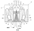
- the fluorescence detector 10 includes a housing 12 that is watertightly sealed inside the cover 11.
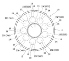
- the housing 12 is provided with a light receiving unit arrangement portion 13 penetrating in the center, and a plurality (9) of light emitting unit arrangement portions 16 are provided at predetermined intervals in the circumferential direction around the light receiving unit arrangement portion 13. (See FIG. 2).
- a light receiving window 15 through which light is incident from the outside is provided at the tip of the light receiving unit arrangement portion 13, and a light receiving interference filter 23 ⁇ / b> A is provided between the light receiving unit arrangement portion 13 and the light receiving window 15.
- the light emitting unit arrangement part 16 is provided with an inclination at a predetermined angle so that the axis thereof intersects with the axis of the light receiving unit arrangement part 13.
- a light transmission window 18 for irradiating excitation light to the outside is provided at the tip of the light emitting unit arrangement portion 16, and light transmission interference is provided between the light emission unit arrangement portion 16 and the light transmission window 18.
- a filter 32 is provided.
- the light receiving unit disposed in the light receiving unit disposed portion 13 includes a light receiving element 20, light receiving interference filters 23 ⁇ / b> A and 23 ⁇ / b> B, a condensing lens 24, and a diaphragm member 25.
- each component except the light receiving interference filter 23A is disposed inside a cylindrical shield member 27.
- the condenser lens 24 and the diaphragm member 25 are positioned with a predetermined interval by a spacer 29.
- the light receiving element 20 of the present embodiment is a photodiode, is fixed to the end of the shield member 27, and is disposed in the light receiving unit disposition portion 13 so as to be located on the side opposite to the light receiving window 15.
- the light receiving element 20 has a light receiving band of 320 to 1100 nm, and generates (detects) a current corresponding to the amount of received light when light in that band is incident on the element surface 21.
- a shielded electric wire 22 for outputting the generated current to the conversion unit 1 is connected to the light receiving element 20.
- the light receiving interference filters 23A and 23B extend in a direction orthogonal to the light receiving axis of the light receiving element 20, and are disposed on the light receiving window 15 side with respect to the light receiving element 20.
- the first light receiving interference filter 23 ⁇ / b> A is disposed so as to be positioned between the condenser lens 24 and the light receiving window 15, and is positioned and held by forming the light receiving window 15.
- the second light receiving interference filter 23 ⁇ / b> B is positioned and held between the light receiving element 20 and the diaphragm member 25 so as to be sandwiched between them.
- These light receiving interference filters 23A and 23B transmit incident light of 640 nm to 1100 nm and cut incident light of other wavelengths, and have high cut-off accuracy of incident light with an incident angle of 0 ° C.
- the condenser lens 24 is disposed between the light receiving window 15 and the light receiving element 20 by being disposed on the tip side of the shield member 27 so as to be positioned on the opposite side to the light receiving element 20.
- the condensing lens 24 condenses incident light incident in parallel along the light receiving axis of the light receiving element 20 from the light receiving window 15 on the element surface 21 of the light receiving element 20.
- a plano-convex lens having a curvature on which the element surface 21 is a focal point is used on the light receiving window 15 side.
- the condenser lens 24 is not limited to a plano-convex lens, and a Fresnel lens may be used.
- the diaphragm member 25 is made of an annular member, and is disposed in the shield member 27 so as to be positioned between the light receiving element 20 and the condenser lens 24.
- the center of the diaphragm member 25 is a transmission hole 26 that can transmit light, and the diameter thereof is slightly larger than the diameter of the passing portion of the condensing region (light beam) by the condensing lens 24 shown with light ink.
- the outside of the transmission hole 26 of the diaphragm member 25 is a light-shielding portion that cannot transmit light, and light that reaches a blocking region other than the condensing region, that is, light that does not converge toward the element surface 21 (focal point). Passing to the light receiving element 20 side is prevented.
- the shield member 27 is made of a metal cylindrical member and extends from the outer periphery of the light receiving element 20 toward the light receiving window 15 so that the axis line coincides with the light receiving axis of the light receiving element 20.
- a condenser lens 24, a spacer 29, a diaphragm member 25, a second light receiving interference filter 23 ⁇ / b> B, and a light receiving element 20 are disposed in this order from the light receiving window 15 side. Blocks external electromagnetic noise applied to the A signal ground connection electric wire 28 is connected to the shield member 27.
- the spacer 29 is made of an aluminum cylindrical member whose outer diameter is substantially the same as the inner diameter of the shield member 27.
- the spacer 29 positions the light receiving element 20 and the condenser lens 24 at a predetermined interval so that the element surface 21 of the light receiving element 20 and the focal point of the condenser lens 24 coincide with each other.
- the condensing lens 24 is positioned between the condensing lens 24 and the diaphragm member 25, thereby positioning the condensing lens 24 on the light receiving interference filter 23A side, and the diaphragm member 25 and the light receiving interference filter 23B. Position on the light receiving element 20 side.
- each light emitting unit disposed in each light emitting unit disposing portion 16 includes light emitting elements 30A to 30I and a light transmission interference filter 32.
- the light emitting elements 30A to 30I are connected to the conversion unit 1 by the electric power supply wire 31 and irradiate the excitation light through the light transmission window 18 with the optical axis toward the lower center.
- an LED light emitting diode
- the wavelength of the excitation light irradiated for each light emitting unit arrangement portion 16 is different at less than 610 nm.
- the light emitting element 30A has a center wavelength of 375 nm
- the light emitting element 30B has a center wavelength of 400 nm
- the light emitting element 30C has a center wavelength of 420 nm
- the light emitting element 30D has a center wavelength of 435 nm
- the light emitting element 30E has a center wavelength of 470 nm
- the light emitting element 30F has a center.
- the light emission element 30G emits excitation light having a wavelength of 505 nm
- the light emission element 30G has a central wavelength of 525 nm
- the light emission element 30H has a central wavelength of 570 nm
- the light emission element 30I has a central wavelength of 590 nm.
- the light transmission interference filter 32 is disposed between the light emitting elements 30A to 30I and the light transmission window 18 so as to extend in a direction orthogonal to the irradiation direction of the light emitting elements 30A to 30I. Is held by positioning. These light transmission interference filters 32 cut wavelengths other than the wavelength of the excitation light irradiated by the corresponding light emitting elements 30A to 30I.
- the thus configured fluorescence detector 10 is connected to the data processing device 2 via the conversion unit 1 and operates in accordance with the instructions of the data processing device 2.
- predetermined light emitting elements 30A to 30I are operated in accordance with an instruction from the data processing apparatus 2, and excitation light having a predetermined wavelength is irradiated from the housing 12 to the outside through the light transmission interference filter 32 and the light transmission window 18.
- the phytoplankton in the water is excited to emit fluorescence, and this fluorescence enters the housing 12 through the light receiving window 15.
- the excitation light irradiated from the light transmission window 18 is blocked by the light shielding wall portion 19 and therefore does not enter the light receiving window 15 directly.
- the incident light transmitted through the light receiving window 15 includes fluorescence due to phytoplankton and stray light such as scattered light and reflected light of excitation light. Further, as shown in FIG. 1, the incident light includes parallel incident light parallel to the light receiving axis of the light receiving element 20 and oblique incident light in a direction intersecting the light receiving axis. Among the parallel incident light, the first stray light other than the predetermined wavelength is cut by the interference filter 23A, and only the fluorescent light having the predetermined wavelength is transmitted. Further, the obliquely incident light that is the second stray light is basically cut by the interference filter 23A, but a part thereof is transmitted through the interference filter 23A.
- the parallel incident light including the fluorescence transmitted through the light receiving interference filter 23A is refracted by the condenser lens 24 so as to be focused on the element surface 21 of the light receiving element 20.
- stray light having a wavelength outside the detection target is cut by the light receiving interference filter 23 ⁇ / b> B and is incident on the light receiving element 20.
- the obliquely incident light that is the second stray light transmitted through the light receiving interference filter 23A is refracted by the condenser lens 24 in the optical path that reaches the blocking region other than the condensing region.
- the condenser lens 24 it is blocked by the diaphragm member 25.
- the fluorescence detector 10 of the present embodiment can block stray light out of the incident light from the light receiving window 15 and detect only the fluorescence to be detected by the light receiving element 20. Therefore, measurement in lakes, dams, water and sewage facilities with high suspended solids concentration is possible, and it can be used in a wide range of applications. In addition, since it is not necessary to make the opening of the light receiving window 15 small and the optical path length from the light receiving window 15 to the light receiving element 20 does not become long, measurement with higher sensitivity can be realized as compared with these methods.
- the light transmission interference filter 32 is disposed on the light emitting elements 30A to 30I side, and the pair of light reception interference filters 23A and 23B are disposed on the light receiving element 20 side. Fluorescence can be detected.
- the wavelengths of the excitation light irradiated by the plurality of light emitting elements 30A to 30I are made different from each other.
- the fluorescence excitation spectrum of the phytoplankton which is a fluorescence characteristic that depends on the pigment composition that serves as an indicator of the seed composition, is automatically and continuously sensitive in water without the need for pretreatment such as pigment extraction. It can be measured. And it is possible to obtain the phytoplankton seed composition and the existing quantity by mathematically analyzing the measured fluorescence excitation spectrum by the data processing device 2.
- the housing 12 is formed in such a dimension that the inner diameter of the light receiving unit disposition portion 13 is formed substantially the same as the outer diameter of the spacer 29 and the light receiving element 20 can be disposed at the focal point of the condenser lens 24. .
- the shield member 33 is disposed so as to be sandwiched between the light receiving element 20 and the second light receiving interference filter 23 ⁇ / b> B, so that the shield member 33 is superimposed on the light receiving window 15 side surface of the light receiving element 20.
- the shield member 33 has a configuration in which a wire mesh member such as a wire mesh, an expanded metal, a punching metal or the like that secures translucency is formed into a disk shape.
- the shield member 33 is not limited to a wire mesh member, and may be formed of a conductive transparent film having translucency.
- the fluorescence detector 10 of the second embodiment configured as described above is connected to the data processing device 2 via the conversion unit 1 in the same manner as in the first embodiment, and is operated according to an instruction of the data processing device 2. Then, when excitation light is irradiated from the light transmission window 18 by the predetermined light emitting elements 30A to 30I and incident light including fluorescence and stray light is incident from the light receiving window 15, the light receiving interference filter 23A, the condensing lens 24, and the diaphragm The stray light can be blocked by the member 25 and only the fluorescence can be detected by the light receiving element 20. Moreover, since the electromagnetic noise from the outside to the light receiving element 20 can be blocked by the shield member 33, the sensitivity of detection by the light receiving element 20 can be increased. Therefore, the same operations and effects as those of the first embodiment can be obtained.
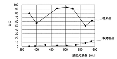
- the product of the present invention shown in the first embodiment and the conventional product in which the condenser lens 24, the diaphragm member 25, and the second light receiving interference filter 23B are not provided were used.
- the product of the present invention and the conventional product were tested with a rhodamine aqueous solution, the product of the present invention and the conventional product were put in a formazine solution (200 FTU), and the respective outputs were measured.
- the experimental results are shown in FIG.
- the horizontal axis represents the excitation light wavelength nm
- the vertical axis represents the output values of the product of the present invention and the conventional product.
- the fluorescence intensity of the target excited by each excitation light is shown on the vertical axis.
- the formazine solution measured in this experiment is not a fluorescent substance, nothing should be shown on the vertical axis. Therefore, in this graph, the higher the output value, the more the stray light such as the scattered light or reflected light of the excitation light is detected due to the influence of turbidity.
- the conventional product was 50 even at the wavelength having the least influence, and 94 at the wavelength having the most influence.
- the product of the present invention was 0 at the wavelength having the least influence and 12 at the wavelength having the most influence.
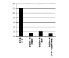
- this graph shows detection for all the light emitting elements 30A to 30I having different wavelengths, and only detection for the light emitting element 30H having a central wavelength of 570 nm, which is the highest value in common for all detectors. .
- the standard deviation of the zero point noise is 12.2 and the electromagnetic noise is very large in the conventional product, which affects the detection.
- the products 1 to 3 of the present invention have a standard deviation of zero point noise of 2.2 or less, and can greatly block electromagnetic noise, so that it is possible to detect with high sensitivity.
- the product 3 of the present invention has a standard deviation of zero point noise of 1.3, and can be reduced to about 1/10 of electromagnetic noise as compared with the conventional product.
- the numerical value of the wavelength with the lowest standard deviation of zero point noise is 1.6 for the conventional product, 0.3 for the product 1 of the present invention, 0.5 for the product 2 of the present invention, and 0.4 for the product 3 of the present invention. Even if the wavelength is low, the products 1 to 3 of the present invention are superior to the conventional products.
- the product of the present invention can greatly reduce the influence of suspended solids and can greatly reduce electromagnetic noise, and can detect with high accuracy and high sensitivity compared to the conventional product. . Therefore, the fluorescence measuring apparatus according to the present invention can contribute to a wide range of mapping of phytoplankton species composition required in earth science, fisheries science and the like.
- the obtained data becomes basic data for material circulation and fisheries management including carbon in the hydrosphere and can be returned to the general public.
- the fluorescence measuring apparatus using the fluorescence detector 10 of the present embodiment can detect a weak fluorescence excitation spectrum change that appears in the initial generation stage of a specific phytoplankton species. Therefore, this device can enhance the effect and efficiency of monitoring and predicting the change in the seed composition that occurs on site.
- fluorescence detector 10 of the present invention is not limited to the configuration of the above embodiment, and various modifications can be made.
- the pair of light receiving interference filters 23A and 23B is provided, but only one of them may be provided.
- the light receiving element 20 and the light emitting elements 30A to 30I are arranged in the same housing 12, they may be arranged in different housings.
- the wavelength and number of light emitted and detected by the light emitting elements 30A to 30I and the light receiving element 20 can be changed as desired.
- the multiwavelength fluorescence detector 10 equipped with the light emitting elements 30A to 30I having different wavelengths of excitation light to be irradiated is used as an example, and a multiwavelength fluorescence measuring apparatus capable of detecting a change in the fluorescence excitation spectrum is taken as an example.
- a single-wavelength fluorescence detector 10 having only a single wavelength may be used.
- the data processing device 2 does not require a complicated analysis program.
- the single-wavelength fluorescence detector 10 it is preferable that a plurality of light-emitting elements that emit excitation light having the same wavelength be disposed in the circumferential direction. In this way, since it is possible to irradiate strong excitation light, it becomes possible to perform detection with higher sensitivity.
- a cylindrical shield member 27 is used, and in the second embodiment, a disk-shaped shield member 33 is used to block electromagnetic noise from the outside to the light receiving element 20.
- the spacer 29 may be made of metal so that it also serves as a shield member.
Landscapes
- Health & Medical Sciences (AREA)
- Nuclear Medicine, Radiotherapy & Molecular Imaging (AREA)
- Physics & Mathematics (AREA)
- Life Sciences & Earth Sciences (AREA)
- Chemical & Material Sciences (AREA)
- Analytical Chemistry (AREA)
- Biochemistry (AREA)
- General Health & Medical Sciences (AREA)
- General Physics & Mathematics (AREA)
- Immunology (AREA)
- Pathology (AREA)
- Investigating, Analyzing Materials By Fluorescence Or Luminescence (AREA)
Applications Claiming Priority (2)
| Application Number | Priority Date | Filing Date | Title |
|---|---|---|---|
| JP2012-137986 | 2012-06-19 | ||
| JP2012137986A JP5627644B2 (ja) | 2012-06-19 | 2012-06-19 | 蛍光検出器 |
Publications (1)
| Publication Number | Publication Date |
|---|---|
| WO2013191135A1 true WO2013191135A1 (ja) | 2013-12-27 |
Family
ID=49768731
Family Applications (1)
| Application Number | Title | Priority Date | Filing Date |
|---|---|---|---|
| PCT/JP2013/066602 Ceased WO2013191135A1 (ja) | 2012-06-19 | 2013-06-17 | 蛍光検出器 |
Country Status (2)
| Country | Link |
|---|---|
| JP (1) | JP5627644B2 (enExample) |
| WO (1) | WO2013191135A1 (enExample) |
Families Citing this family (2)
| Publication number | Priority date | Publication date | Assignee | Title |
|---|---|---|---|---|
| JP2676923B2 (ja) | 1989-06-21 | 1997-11-17 | 石川島播磨重工業株式会社 | 単純桁方式の多径間道路橋への修復方法 |
| KR102376680B1 (ko) * | 2020-07-06 | 2022-03-18 | 한림대학교 산학협력단 | 스테인드 글라스 방식의 다중채널 형광 검출 장치 |
Citations (10)
| Publication number | Priority date | Publication date | Assignee | Title |
|---|---|---|---|---|
| JPS61186835A (ja) * | 1985-02-14 | 1986-08-20 | Omron Tateisi Electronics Co | 流れ式粒子分析装置 |
| JPH0670582B2 (ja) * | 1989-05-02 | 1994-09-07 | 宇宙開発事業団 | 開口部を有する光学センサの電磁シールド方式 |
| JPH08261934A (ja) * | 1995-03-17 | 1996-10-11 | Aretsuku Denshi Kk | 蛍光検出器 |
| JPH1164222A (ja) * | 1997-08-26 | 1999-03-05 | Nec Corp | 蛍光検出装置及び蛍光検出方法 |
| JP2001087250A (ja) * | 1999-08-30 | 2001-04-03 | Cas Medical Systems Inc | 近赤外線分光測光検査装置 |
| JP2003507718A (ja) * | 1999-08-26 | 2003-02-25 | マシモ・コーポレイション | シールド付き光学プローブ及び方法 |
| WO2006103932A1 (ja) * | 2005-03-29 | 2006-10-05 | National University Corporation Tokyo University Of Marine Science And Technology | 植物プランクトンの分布計測方法及びその装置 |
| JP2008522160A (ja) * | 2004-11-24 | 2008-06-26 | アイデックス ラボラトリーズ インコーポレイテッド | 化学分析装置において使用する反射率計および関連の光源 |
| JP2009178078A (ja) * | 2008-01-30 | 2009-08-13 | Hitachi Engineering & Services Co Ltd | 微生物検査チップ及び微生物検査装置 |
| JP4724559B2 (ja) * | 2005-12-28 | 2011-07-13 | 日本電信電話株式会社 | 光学センサ及びそのセンサ部 |
-
2012
- 2012-06-19 JP JP2012137986A patent/JP5627644B2/ja active Active
-
2013
- 2013-06-17 WO PCT/JP2013/066602 patent/WO2013191135A1/ja not_active Ceased
Patent Citations (10)
| Publication number | Priority date | Publication date | Assignee | Title |
|---|---|---|---|---|
| JPS61186835A (ja) * | 1985-02-14 | 1986-08-20 | Omron Tateisi Electronics Co | 流れ式粒子分析装置 |
| JPH0670582B2 (ja) * | 1989-05-02 | 1994-09-07 | 宇宙開発事業団 | 開口部を有する光学センサの電磁シールド方式 |
| JPH08261934A (ja) * | 1995-03-17 | 1996-10-11 | Aretsuku Denshi Kk | 蛍光検出器 |
| JPH1164222A (ja) * | 1997-08-26 | 1999-03-05 | Nec Corp | 蛍光検出装置及び蛍光検出方法 |
| JP2003507718A (ja) * | 1999-08-26 | 2003-02-25 | マシモ・コーポレイション | シールド付き光学プローブ及び方法 |
| JP2001087250A (ja) * | 1999-08-30 | 2001-04-03 | Cas Medical Systems Inc | 近赤外線分光測光検査装置 |
| JP2008522160A (ja) * | 2004-11-24 | 2008-06-26 | アイデックス ラボラトリーズ インコーポレイテッド | 化学分析装置において使用する反射率計および関連の光源 |
| WO2006103932A1 (ja) * | 2005-03-29 | 2006-10-05 | National University Corporation Tokyo University Of Marine Science And Technology | 植物プランクトンの分布計測方法及びその装置 |
| JP4724559B2 (ja) * | 2005-12-28 | 2011-07-13 | 日本電信電話株式会社 | 光学センサ及びそのセンサ部 |
| JP2009178078A (ja) * | 2008-01-30 | 2009-08-13 | Hitachi Engineering & Services Co Ltd | 微生物検査チップ及び微生物検査装置 |
Non-Patent Citations (1)
| Title |
|---|
| MITSUO YOSHIDA ET AL.: "In Situ Multi- Excitation Chlorophyll Fluorometer for Phytoplankton Measurements", DAI 24 KAI THE SOCIETY OF ENVIRONMENTAL INSTRUMENTATION CONTROL AND AUTOMATION(EICA) KENKYU HAPPYOKAI KOEN GAIYOSHU, vol. 17, no. 2/3, 15 October 2012 (2012-10-15), pages 177 - 179 * |
Also Published As
| Publication number | Publication date |
|---|---|
| JP2014002062A (ja) | 2014-01-09 |
| JP5627644B2 (ja) | 2014-11-19 |
Similar Documents
| Publication | Publication Date | Title |
|---|---|---|
| Zeng et al. | Development of in situ sensors for chlorophyll concentration measurement | |
| JP6804445B2 (ja) | 吸光度測定装置への蛍光検出機能の統合 | |
| JP4220374B2 (ja) | マルチチャネル蛍光センサ | |
| RU2541178C2 (ru) | Светоизлучающий участок, фотоэлектрический датчик дыма и система всасывающего типа для определения присутствия дыма | |
| JP6360430B2 (ja) | 波長の中心検出に基づいたセンサ装置および方法 | |
| RU2010117396A (ru) | Компоненты оптического устройства | |
| KR20180041688A (ko) | 다중 파라미터 수질 모니터링을 위한 다중 여기-다중 방출 형광계 | |
| JP2020523592A5 (enExample) | ||
| CA2964020C (en) | Optical gas sensor comprising an led emitter for the emission of light of a narrow bandwidth | |
| KR102094582B1 (ko) | Uv 살균 설비를 모니터링하기 위한 작동 방법 및 장치 | |
| US10890525B2 (en) | Infrared analytical sensor for soil or water and method of operation thereof | |
| CN102171548A (zh) | 适于对高浓度气体进行光谱分析的设备 | |
| JP5627644B2 (ja) | 蛍光検出器 | |
| JP2016121926A (ja) | 光学分析装置 | |
| CN109564163A (zh) | 用于确定液体介质中的物质的浓度的方法和设备 | |
| KR20170052256A (ko) | 라만 산란을 이용한 물질의 농도 측정 장치 및 방법 | |
| CN105300930A (zh) | 双通道水质浊度检测方法 | |
| CN110018137A (zh) | 光学传感器 | |
| KR101727009B1 (ko) | 흡광신호 및 형광신호를 이용한 미세입자 측정장치 및 데이터 보정방법 | |
| CN201611335U (zh) | 一种黄色物质水下荧光探测装置 | |
| CN204374087U (zh) | 一种基于液芯波导的拉曼光谱测试系统 | |
| JP2020085615A (ja) | 光学測定器 | |
| JP2010238095A (ja) | 光電式煙感知器 | |
| CN104614363A (zh) | 一种基于液芯波导的拉曼光谱测试系统 | |
| JP2015227858A5 (enExample) |
Legal Events
| Date | Code | Title | Description |
|---|---|---|---|
| 121 | Ep: the epo has been informed by wipo that ep was designated in this application |
Ref document number: 13807172 Country of ref document: EP Kind code of ref document: A1 |
|
| NENP | Non-entry into the national phase |
Ref country code: DE |
|
| 122 | Ep: pct application non-entry in european phase |
Ref document number: 13807172 Country of ref document: EP Kind code of ref document: A1 |