WO2013187632A1 - 담체 공극 매몰형 scr 촉매 구조체 - Google Patents
담체 공극 매몰형 scr 촉매 구조체 Download PDFInfo
- Publication number
- WO2013187632A1 WO2013187632A1 PCT/KR2013/005002 KR2013005002W WO2013187632A1 WO 2013187632 A1 WO2013187632 A1 WO 2013187632A1 KR 2013005002 W KR2013005002 W KR 2013005002W WO 2013187632 A1 WO2013187632 A1 WO 2013187632A1
- Authority
- WO
- WIPO (PCT)
- Prior art keywords
- carrier
- scr catalyst
- catalytically active
- catalyst
- active material
- Prior art date
Links
- 239000003054 catalyst Substances 0.000 title claims abstract description 87
- 239000011148 porous material Substances 0.000 title claims abstract description 17
- 239000011149 active material Substances 0.000 claims abstract description 32
- NINIDFKCEFEMDL-UHFFFAOYSA-N Sulfur Chemical compound [S] NINIDFKCEFEMDL-UHFFFAOYSA-N 0.000 claims abstract description 14
- 229910052717 sulfur Inorganic materials 0.000 claims abstract description 14
- 239000011593 sulfur Substances 0.000 claims abstract description 14
- 239000007789 gas Substances 0.000 claims description 25
- MWUXSHHQAYIFBG-UHFFFAOYSA-N nitrogen oxide Inorganic materials O=[N] MWUXSHHQAYIFBG-UHFFFAOYSA-N 0.000 claims description 12
- 229910052878 cordierite Inorganic materials 0.000 claims description 10
- JSKIRARMQDRGJZ-UHFFFAOYSA-N dimagnesium dioxido-bis[(1-oxido-3-oxo-2,4,6,8,9-pentaoxa-1,3-disila-5,7-dialuminabicyclo[3.3.1]nonan-7-yl)oxy]silane Chemical group [Mg++].[Mg++].[O-][Si]([O-])(O[Al]1O[Al]2O[Si](=O)O[Si]([O-])(O1)O2)O[Al]1O[Al]2O[Si](=O)O[Si]([O-])(O1)O2 JSKIRARMQDRGJZ-UHFFFAOYSA-N 0.000 claims description 10
- 229910052720 vanadium Inorganic materials 0.000 claims description 7
- GFQYVLUOOAAOGM-UHFFFAOYSA-N zirconium(iv) silicate Chemical compound [Zr+4].[O-][Si]([O-])([O-])[O-] GFQYVLUOOAAOGM-UHFFFAOYSA-N 0.000 claims description 7
- HNPSIPDUKPIQMN-UHFFFAOYSA-N dioxosilane;oxo(oxoalumanyloxy)alumane Chemical compound O=[Si]=O.O=[Al]O[Al]=O HNPSIPDUKPIQMN-UHFFFAOYSA-N 0.000 claims description 6
- LEONUFNNVUYDNQ-UHFFFAOYSA-N vanadium atom Chemical compound [V] LEONUFNNVUYDNQ-UHFFFAOYSA-N 0.000 claims description 6
- 229910052845 zircon Inorganic materials 0.000 claims description 6
- BPQQTUXANYXVAA-UHFFFAOYSA-N Orthosilicate Chemical compound [O-][Si]([O-])([O-])[O-] BPQQTUXANYXVAA-UHFFFAOYSA-N 0.000 claims description 5
- GWEVSGVZZGPLCZ-UHFFFAOYSA-N Titan oxide Chemical compound O=[Ti]=O GWEVSGVZZGPLCZ-UHFFFAOYSA-N 0.000 claims description 5
- 238000000034 method Methods 0.000 claims description 4
- PNEYBMLMFCGWSK-UHFFFAOYSA-N Alumina Chemical compound [O-2].[O-2].[O-2].[Al+3].[Al+3] PNEYBMLMFCGWSK-UHFFFAOYSA-N 0.000 claims description 3
- 229910052581 Si3N4 Inorganic materials 0.000 claims description 3
- 229910021536 Zeolite Inorganic materials 0.000 claims description 3
- 229910000323 aluminium silicate Inorganic materials 0.000 claims description 3
- HEHRHMRHPUNLIR-UHFFFAOYSA-N aluminum;hydroxy-[hydroxy(oxo)silyl]oxy-oxosilane;lithium Chemical compound [Li].[Al].O[Si](=O)O[Si](O)=O.O[Si](=O)O[Si](O)=O HEHRHMRHPUNLIR-UHFFFAOYSA-N 0.000 claims description 3
- 239000010953 base metal Substances 0.000 claims description 3
- HCWCAKKEBCNQJP-UHFFFAOYSA-N magnesium orthosilicate Chemical compound [Mg+2].[Mg+2].[O-][Si]([O-])([O-])[O-] HCWCAKKEBCNQJP-UHFFFAOYSA-N 0.000 claims description 3
- 239000000395 magnesium oxide Substances 0.000 claims description 3
- CPLXHLVBOLITMK-UHFFFAOYSA-N magnesium oxide Inorganic materials [Mg]=O CPLXHLVBOLITMK-UHFFFAOYSA-N 0.000 claims description 3
- 239000000391 magnesium silicate Substances 0.000 claims description 3
- 229910052919 magnesium silicate Inorganic materials 0.000 claims description 3
- 235000019792 magnesium silicate Nutrition 0.000 claims description 3
- 229910044991 metal oxide Inorganic materials 0.000 claims description 3
- 150000004706 metal oxides Chemical class 0.000 claims description 3
- JKQOBWVOAYFWKG-UHFFFAOYSA-N molybdenum trioxide Chemical compound O=[Mo](=O)=O JKQOBWVOAYFWKG-UHFFFAOYSA-N 0.000 claims description 3
- 229910052670 petalite Inorganic materials 0.000 claims description 3
- HBMJWWWQQXIZIP-UHFFFAOYSA-N silicon carbide Chemical compound [Si+]#[C-] HBMJWWWQQXIZIP-UHFFFAOYSA-N 0.000 claims description 3
- 229910010271 silicon carbide Inorganic materials 0.000 claims description 3
- HQVNEWCFYHHQES-UHFFFAOYSA-N silicon nitride Chemical compound N12[Si]34N5[Si]62N3[Si]51N64 HQVNEWCFYHHQES-UHFFFAOYSA-N 0.000 claims description 3
- ZNOKGRXACCSDPY-UHFFFAOYSA-N tungsten trioxide Chemical compound O=[W](=O)=O ZNOKGRXACCSDPY-UHFFFAOYSA-N 0.000 claims description 3
- 239000010457 zeolite Substances 0.000 claims description 3
- CNLWCVNCHLKFHK-UHFFFAOYSA-N aluminum;lithium;dioxido(oxo)silane Chemical compound [Li+].[Al+3].[O-][Si]([O-])=O.[O-][Si]([O-])=O CNLWCVNCHLKFHK-UHFFFAOYSA-N 0.000 claims description 2
- 229910010293 ceramic material Inorganic materials 0.000 claims description 2
- KZHJGOXRZJKJNY-UHFFFAOYSA-N dioxosilane;oxo(oxoalumanyloxy)alumane Chemical compound O=[Si]=O.O=[Si]=O.O=[Al]O[Al]=O.O=[Al]O[Al]=O.O=[Al]O[Al]=O KZHJGOXRZJKJNY-UHFFFAOYSA-N 0.000 claims description 2
- 229910052863 mullite Inorganic materials 0.000 claims description 2
- 229910052642 spodumene Inorganic materials 0.000 claims description 2
- 239000011800 void material Substances 0.000 claims description 2
- 230000003197 catalytic effect Effects 0.000 abstract description 10
- QAOWNCQODCNURD-UHFFFAOYSA-N Sulfuric acid Chemical compound OS(O)(=O)=O QAOWNCQODCNURD-UHFFFAOYSA-N 0.000 description 10
- 239000011248 coating agent Substances 0.000 description 10
- 238000000576 coating method Methods 0.000 description 10
- 238000000151 deposition Methods 0.000 description 10
- 230000008021 deposition Effects 0.000 description 8
- 239000000463 material Substances 0.000 description 8
- 239000002002 slurry Substances 0.000 description 8
- 238000011156 evaluation Methods 0.000 description 7
- QGZKDVFQNNGYKY-UHFFFAOYSA-N Ammonia Chemical compound N QGZKDVFQNNGYKY-UHFFFAOYSA-N 0.000 description 6
- 230000000694 effects Effects 0.000 description 6
- 229910010413 TiO 2 Inorganic materials 0.000 description 4
- 239000004480 active ingredient Substances 0.000 description 4
- GNTDGMZSJNCJKK-UHFFFAOYSA-N divanadium pentaoxide Chemical compound O=[V](=O)O[V](=O)=O GNTDGMZSJNCJKK-UHFFFAOYSA-N 0.000 description 4
- 238000001125 extrusion Methods 0.000 description 4
- 229910021529 ammonia Inorganic materials 0.000 description 3
- 239000012530 fluid Substances 0.000 description 3
- 239000000446 fuel Substances 0.000 description 3
- IJGRMHOSHXDMSA-UHFFFAOYSA-N Atomic nitrogen Chemical compound N#N IJGRMHOSHXDMSA-UHFFFAOYSA-N 0.000 description 2
- 238000001354 calcination Methods 0.000 description 2
- 238000006243 chemical reaction Methods 0.000 description 2
- -1 cordierite-α-alumina Chemical compound 0.000 description 2
- 238000009826 distribution Methods 0.000 description 2
- 239000007769 metal material Substances 0.000 description 2
- 229910052757 nitrogen Inorganic materials 0.000 description 2
- 229910052760 oxygen Inorganic materials 0.000 description 2
- XLYOFNOQVPJJNP-UHFFFAOYSA-N water Substances O XLYOFNOQVPJJNP-UHFFFAOYSA-N 0.000 description 2
- 239000013543 active substance Substances 0.000 description 1
- 239000000654 additive Substances 0.000 description 1
- 230000000996 additive effect Effects 0.000 description 1
- 239000011230 binding agent Substances 0.000 description 1
- 239000000969 carrier Substances 0.000 description 1
- 238000010531 catalytic reduction reaction Methods 0.000 description 1
- 239000000919 ceramic Substances 0.000 description 1
- 239000011247 coating layer Substances 0.000 description 1
- 239000000470 constituent Substances 0.000 description 1
- 238000007796 conventional method Methods 0.000 description 1
- 238000007598 dipping method Methods 0.000 description 1
- 239000000428 dust Substances 0.000 description 1
- 238000002474 experimental method Methods 0.000 description 1
- 238000011049 filling Methods 0.000 description 1
- 230000009970 fire resistant effect Effects 0.000 description 1
- 238000007654 immersion Methods 0.000 description 1
- 229910010272 inorganic material Inorganic materials 0.000 description 1
- 239000011147 inorganic material Substances 0.000 description 1
- 238000004519 manufacturing process Methods 0.000 description 1
- 239000000155 melt Substances 0.000 description 1
- 239000010747 number 6 fuel oil Substances 0.000 description 1
- 239000003921 oil Substances 0.000 description 1
- 238000002360 preparation method Methods 0.000 description 1
- 230000002035 prolonged effect Effects 0.000 description 1
- 239000002994 raw material Substances 0.000 description 1
- 239000011214 refractory ceramic Substances 0.000 description 1
- 230000000717 retained effect Effects 0.000 description 1
- 239000000126 substance Substances 0.000 description 1
- 239000004408 titanium dioxide Substances 0.000 description 1
Images


Classifications
-
- B—PERFORMING OPERATIONS; TRANSPORTING
- B01—PHYSICAL OR CHEMICAL PROCESSES OR APPARATUS IN GENERAL
- B01J—CHEMICAL OR PHYSICAL PROCESSES, e.g. CATALYSIS OR COLLOID CHEMISTRY; THEIR RELEVANT APPARATUS
- B01J23/00—Catalysts comprising metals or metal oxides or hydroxides, not provided for in group B01J21/00
- B01J23/16—Catalysts comprising metals or metal oxides or hydroxides, not provided for in group B01J21/00 of arsenic, antimony, bismuth, vanadium, niobium, tantalum, polonium, chromium, molybdenum, tungsten, manganese, technetium or rhenium
- B01J23/24—Chromium, molybdenum or tungsten
-
- B—PERFORMING OPERATIONS; TRANSPORTING
- B01—PHYSICAL OR CHEMICAL PROCESSES OR APPARATUS IN GENERAL
- B01J—CHEMICAL OR PHYSICAL PROCESSES, e.g. CATALYSIS OR COLLOID CHEMISTRY; THEIR RELEVANT APPARATUS
- B01J37/00—Processes, in general, for preparing catalysts; Processes, in general, for activation of catalysts
- B01J37/02—Impregnation, coating or precipitation
-
- B—PERFORMING OPERATIONS; TRANSPORTING
- B01—PHYSICAL OR CHEMICAL PROCESSES OR APPARATUS IN GENERAL
- B01D—SEPARATION
- B01D53/00—Separation of gases or vapours; Recovering vapours of volatile solvents from gases; Chemical or biological purification of waste gases, e.g. engine exhaust gases, smoke, fumes, flue gases, aerosols
- B01D53/34—Chemical or biological purification of waste gases
- B01D53/46—Removing components of defined structure
- B01D53/54—Nitrogen compounds
- B01D53/56—Nitrogen oxides
-
- B—PERFORMING OPERATIONS; TRANSPORTING
- B01—PHYSICAL OR CHEMICAL PROCESSES OR APPARATUS IN GENERAL
- B01D—SEPARATION
- B01D53/00—Separation of gases or vapours; Recovering vapours of volatile solvents from gases; Chemical or biological purification of waste gases, e.g. engine exhaust gases, smoke, fumes, flue gases, aerosols
- B01D53/34—Chemical or biological purification of waste gases
- B01D53/74—General processes for purification of waste gases; Apparatus or devices specially adapted therefor
- B01D53/86—Catalytic processes
- B01D53/8621—Removing nitrogen compounds
- B01D53/8625—Nitrogen oxides
- B01D53/8628—Processes characterised by a specific catalyst
-
- B—PERFORMING OPERATIONS; TRANSPORTING
- B01—PHYSICAL OR CHEMICAL PROCESSES OR APPARATUS IN GENERAL
- B01D—SEPARATION
- B01D53/00—Separation of gases or vapours; Recovering vapours of volatile solvents from gases; Chemical or biological purification of waste gases, e.g. engine exhaust gases, smoke, fumes, flue gases, aerosols
- B01D53/34—Chemical or biological purification of waste gases
- B01D53/92—Chemical or biological purification of waste gases of engine exhaust gases
- B01D53/94—Chemical or biological purification of waste gases of engine exhaust gases by catalytic processes
- B01D53/9404—Removing only nitrogen compounds
- B01D53/9409—Nitrogen oxides
- B01D53/9413—Processes characterised by a specific catalyst
- B01D53/9418—Processes characterised by a specific catalyst for removing nitrogen oxides by selective catalytic reduction [SCR] using a reducing agent in a lean exhaust gas
-
- B—PERFORMING OPERATIONS; TRANSPORTING
- B01—PHYSICAL OR CHEMICAL PROCESSES OR APPARATUS IN GENERAL
- B01J—CHEMICAL OR PHYSICAL PROCESSES, e.g. CATALYSIS OR COLLOID CHEMISTRY; THEIR RELEVANT APPARATUS
- B01J21/00—Catalysts comprising the elements, oxides, or hydroxides of magnesium, boron, aluminium, carbon, silicon, titanium, zirconium, or hafnium
- B01J21/06—Silicon, titanium, zirconium or hafnium; Oxides or hydroxides thereof
- B01J21/063—Titanium; Oxides or hydroxides thereof
-
- B—PERFORMING OPERATIONS; TRANSPORTING
- B01—PHYSICAL OR CHEMICAL PROCESSES OR APPARATUS IN GENERAL
- B01J—CHEMICAL OR PHYSICAL PROCESSES, e.g. CATALYSIS OR COLLOID CHEMISTRY; THEIR RELEVANT APPARATUS
- B01J23/00—Catalysts comprising metals or metal oxides or hydroxides, not provided for in group B01J21/00
- B01J23/16—Catalysts comprising metals or metal oxides or hydroxides, not provided for in group B01J21/00 of arsenic, antimony, bismuth, vanadium, niobium, tantalum, polonium, chromium, molybdenum, tungsten, manganese, technetium or rhenium
- B01J23/20—Vanadium, niobium or tantalum
-
- B—PERFORMING OPERATIONS; TRANSPORTING
- B01—PHYSICAL OR CHEMICAL PROCESSES OR APPARATUS IN GENERAL
- B01J—CHEMICAL OR PHYSICAL PROCESSES, e.g. CATALYSIS OR COLLOID CHEMISTRY; THEIR RELEVANT APPARATUS
- B01J35/00—Catalysts, in general, characterised by their form or physical properties
-
- B—PERFORMING OPERATIONS; TRANSPORTING
- B01—PHYSICAL OR CHEMICAL PROCESSES OR APPARATUS IN GENERAL
- B01J—CHEMICAL OR PHYSICAL PROCESSES, e.g. CATALYSIS OR COLLOID CHEMISTRY; THEIR RELEVANT APPARATUS
- B01J35/00—Catalysts, in general, characterised by their form or physical properties
- B01J35/30—Catalysts, in general, characterised by their form or physical properties characterised by their physical properties
-
- B—PERFORMING OPERATIONS; TRANSPORTING
- B01—PHYSICAL OR CHEMICAL PROCESSES OR APPARATUS IN GENERAL
- B01J—CHEMICAL OR PHYSICAL PROCESSES, e.g. CATALYSIS OR COLLOID CHEMISTRY; THEIR RELEVANT APPARATUS
- B01J35/00—Catalysts, in general, characterised by their form or physical properties
- B01J35/50—Catalysts, in general, characterised by their form or physical properties characterised by their shape or configuration
- B01J35/56—Foraminous structures having flow-through passages or channels, e.g. grids or three-dimensional monoliths
-
- F—MECHANICAL ENGINEERING; LIGHTING; HEATING; WEAPONS; BLASTING
- F01—MACHINES OR ENGINES IN GENERAL; ENGINE PLANTS IN GENERAL; STEAM ENGINES
- F01N—GAS-FLOW SILENCERS OR EXHAUST APPARATUS FOR MACHINES OR ENGINES IN GENERAL; GAS-FLOW SILENCERS OR EXHAUST APPARATUS FOR INTERNAL COMBUSTION ENGINES
- F01N3/00—Exhaust or silencing apparatus having means for purifying, rendering innocuous, or otherwise treating exhaust
- F01N3/08—Exhaust or silencing apparatus having means for purifying, rendering innocuous, or otherwise treating exhaust for rendering innocuous
- F01N3/10—Exhaust or silencing apparatus having means for purifying, rendering innocuous, or otherwise treating exhaust for rendering innocuous by thermal or catalytic conversion of noxious components of exhaust
- F01N3/18—Exhaust or silencing apparatus having means for purifying, rendering innocuous, or otherwise treating exhaust for rendering innocuous by thermal or catalytic conversion of noxious components of exhaust characterised by methods of operation; Control
- F01N3/20—Exhaust or silencing apparatus having means for purifying, rendering innocuous, or otherwise treating exhaust for rendering innocuous by thermal or catalytic conversion of noxious components of exhaust characterised by methods of operation; Control specially adapted for catalytic conversion ; Methods of operation or control of catalytic converters
- F01N3/2066—Selective catalytic reduction [SCR]
-
- B—PERFORMING OPERATIONS; TRANSPORTING
- B01—PHYSICAL OR CHEMICAL PROCESSES OR APPARATUS IN GENERAL
- B01D—SEPARATION
- B01D2255/00—Catalysts
- B01D2255/20—Metals or compounds thereof
- B01D2255/207—Transition metals
- B01D2255/20707—Titanium
-
- B—PERFORMING OPERATIONS; TRANSPORTING
- B01—PHYSICAL OR CHEMICAL PROCESSES OR APPARATUS IN GENERAL
- B01D—SEPARATION
- B01D2255/00—Catalysts
- B01D2255/20—Metals or compounds thereof
- B01D2255/207—Transition metals
- B01D2255/20723—Vanadium
-
- B—PERFORMING OPERATIONS; TRANSPORTING
- B01—PHYSICAL OR CHEMICAL PROCESSES OR APPARATUS IN GENERAL
- B01D—SEPARATION
- B01D2255/00—Catalysts
- B01D2255/20—Metals or compounds thereof
- B01D2255/207—Transition metals
- B01D2255/20769—Molybdenum
-
- B—PERFORMING OPERATIONS; TRANSPORTING
- B01—PHYSICAL OR CHEMICAL PROCESSES OR APPARATUS IN GENERAL
- B01D—SEPARATION
- B01D2255/00—Catalysts
- B01D2255/20—Metals or compounds thereof
- B01D2255/207—Transition metals
- B01D2255/20776—Tungsten
-
- B—PERFORMING OPERATIONS; TRANSPORTING
- B01—PHYSICAL OR CHEMICAL PROCESSES OR APPARATUS IN GENERAL
- B01D—SEPARATION
- B01D2255/00—Catalysts
- B01D2255/50—Zeolites
-
- B—PERFORMING OPERATIONS; TRANSPORTING
- B01—PHYSICAL OR CHEMICAL PROCESSES OR APPARATUS IN GENERAL
- B01D—SEPARATION
- B01D2255/00—Catalysts
- B01D2255/90—Physical characteristics of catalysts
-
- B—PERFORMING OPERATIONS; TRANSPORTING
- B01—PHYSICAL OR CHEMICAL PROCESSES OR APPARATUS IN GENERAL
- B01D—SEPARATION
- B01D2257/00—Components to be removed
- B01D2257/40—Nitrogen compounds
- B01D2257/404—Nitrogen oxides other than dinitrogen oxide
-
- F—MECHANICAL ENGINEERING; LIGHTING; HEATING; WEAPONS; BLASTING
- F01—MACHINES OR ENGINES IN GENERAL; ENGINE PLANTS IN GENERAL; STEAM ENGINES
- F01N—GAS-FLOW SILENCERS OR EXHAUST APPARATUS FOR MACHINES OR ENGINES IN GENERAL; GAS-FLOW SILENCERS OR EXHAUST APPARATUS FOR INTERNAL COMBUSTION ENGINES
- F01N2370/00—Selection of materials for exhaust purification
- F01N2370/02—Selection of materials for exhaust purification used in catalytic reactors
- F01N2370/04—Zeolitic material
-
- F—MECHANICAL ENGINEERING; LIGHTING; HEATING; WEAPONS; BLASTING
- F01—MACHINES OR ENGINES IN GENERAL; ENGINE PLANTS IN GENERAL; STEAM ENGINES
- F01N—GAS-FLOW SILENCERS OR EXHAUST APPARATUS FOR MACHINES OR ENGINES IN GENERAL; GAS-FLOW SILENCERS OR EXHAUST APPARATUS FOR INTERNAL COMBUSTION ENGINES
- F01N2510/00—Surface coverings
- F01N2510/06—Surface coverings for exhaust purification, e.g. catalytic reaction
- F01N2510/068—Surface coverings for exhaust purification, e.g. catalytic reaction characterised by the distribution of the catalytic coatings
-
- F—MECHANICAL ENGINEERING; LIGHTING; HEATING; WEAPONS; BLASTING
- F01—MACHINES OR ENGINES IN GENERAL; ENGINE PLANTS IN GENERAL; STEAM ENGINES
- F01N—GAS-FLOW SILENCERS OR EXHAUST APPARATUS FOR MACHINES OR ENGINES IN GENERAL; GAS-FLOW SILENCERS OR EXHAUST APPARATUS FOR INTERNAL COMBUSTION ENGINES
- F01N3/00—Exhaust or silencing apparatus having means for purifying, rendering innocuous, or otherwise treating exhaust
- F01N3/08—Exhaust or silencing apparatus having means for purifying, rendering innocuous, or otherwise treating exhaust for rendering innocuous
- F01N3/10—Exhaust or silencing apparatus having means for purifying, rendering innocuous, or otherwise treating exhaust for rendering innocuous by thermal or catalytic conversion of noxious components of exhaust
- F01N3/24—Exhaust or silencing apparatus having means for purifying, rendering innocuous, or otherwise treating exhaust for rendering innocuous by thermal or catalytic conversion of noxious components of exhaust characterised by constructional aspects of converting apparatus
- F01N3/28—Construction of catalytic reactors
- F01N3/2803—Construction of catalytic reactors characterised by structure, by material or by manufacturing of catalyst support
- F01N3/2825—Ceramics
- F01N3/2828—Ceramic multi-channel monoliths, e.g. honeycombs
-
- Y—GENERAL TAGGING OF NEW TECHNOLOGICAL DEVELOPMENTS; GENERAL TAGGING OF CROSS-SECTIONAL TECHNOLOGIES SPANNING OVER SEVERAL SECTIONS OF THE IPC; TECHNICAL SUBJECTS COVERED BY FORMER USPC CROSS-REFERENCE ART COLLECTIONS [XRACs] AND DIGESTS
- Y02—TECHNOLOGIES OR APPLICATIONS FOR MITIGATION OR ADAPTATION AGAINST CLIMATE CHANGE
- Y02T—CLIMATE CHANGE MITIGATION TECHNOLOGIES RELATED TO TRANSPORTATION
- Y02T10/00—Road transport of goods or passengers
- Y02T10/10—Internal combustion engine [ICE] based vehicles
- Y02T10/12—Improving ICE efficiencies
Definitions
- the present invention relates to a carrier pore-embedded SCR catalyst structure, and more particularly, to an SCR catalyst which can be applied in high sulfur content exhaust gas treatment, a catalytically active material is deposited inside a carrier, and the catalyst inner wall is substantially catalytically active.
- SCR selective catalytic reduction
- SCR systems are used to reduce the emissions of nitrogen oxides from the exhaust of boilers, engines and furnaces.
- ammonia is injected into the exhaust stream of the boiler with the catalyst.
- Ammonia is converted into water and nitrogen by reducing a large amount of nitrogen oxides from the exhaust gas.
- the denitrogen oxide catalyst used in the SCR system is expensive, it is desirable to be able to control the stoichiometry of the exhaust gas / ammonia / catalyst reaction.
- Catalytically active substances such as denitrogen oxides are supported on a carrier of refractory inorganic material or metal material.
- the catalyst used in the SCR system can be roughly divided into an extruded SCR catalyst and a coated SCR catalyst depending on the preparation method.
- the extrusion type is a structure in which the active material and the carrier constituent material are prepared in the form of a slurry, and then extruded using an extruder, in which the structure is usually manufactured in a honeycomb structure in order to prevent the exhaust gas pressure drop due to the catalyst.
- the coating type is a catalyst having an active material coated on a carrier in a honeycomb form of ceramic or metal material. More specifically, monolithic carriers in the form of fine parallel gas flow passages extending therefrom from the carrier inlet or outlet side of the honeycomb structure can be used, which passages are open so that fluid flows through them.
- the passageway which is a substantially straight path from the fluid inlet to the fluid outlet, is then defined by the inner wall where the catalytically active material is coated as a washcoat so that the exhaust gas flowing through the passages contacts the catalytic material.
- the flow path of the monolithic carrier may be of any suitable cross-sectional shape and size, such as trapezoidal, rectangular, square, sinusoidal, hexagonal, elliptical, circular, etc., and has a thin inner wall structure. Such structures may have from about 60 to about 900 or more gas inlet openings (ie, cells) per square inch of cross section.
- Extruded SCR catalysts are usually applied to power plants and ships.
- the vanadium pentoxide extrusion type catalyst is a fire-resistant supporting material such as titanium dioxide and denitrification active material as vanadium pentoxide as a main raw material.
- a honeycomb extruded catalyst is used that is extruded after the binder additive is added.
- catalysts used in high dust generation such as ships or power plants require considerable mechanical strength, but bunker C oil, which is a fuel for ship diesel engines or coal-fired power plants, contains more than 2% of sulfur. When exposed to sulfur for a long period of time there is a problem that the mechanical strength drops sharply.
- the present invention is proposed to solve the problems of the conventional extruded or coated SCR catalyst applied in the treatment of high sulfur content exhaust gas, and relates to a pore-deposited or buried SCR catalyst structure, and more particularly to a catalytically active material.
- the present invention relates to a deposited SCR catalyst structure which is deposited inside the support and substantially free of catalytically active material on the inner wall of the support.
- the carrier has a honeycomb structure of 20% to 80% porosity, cordierite, silicon carbide, cordierite- ⁇ -alumina, silicon nitride , Zircon mullite, spodumene, alumina-silica-magnesia, zircony silicate, silicate, magnesium silicate, zircon, petalite, ⁇ -alumina, aluminosilicate, and the like, preferably made of cordierite.
- the catalytically active material deposited inside the carrier is a vanadium series in which titanium oxide (TiO 2 ), tungsten oxide (WO 3 ), or molybdenum oxide (MoO 3 ) is added to vanadium, It may be a zeolite-based or base metal oxide, but is not limited thereto.
- the deposited or buried SCR catalyst according to the present invention maintains almost the same compressive strength as new products even after exposure to high sulfur containing exhaust gas, thereby overcoming the mechanical weakness as in conventional extruded structures over time.
- the deposition type SCR catalyst according to the present invention is such that the catalytically active material is deposited in the carrier pores, and thus the catalytically active material is retained even after prolonged exposure to the high sulfur-containing exhaust gas, thereby deviating from the inner wall of the carrier as in the conventional coating structure. The physical loss can be prevented, and the back pressure applied to the catalyst can be lowered because the carrier channel space is relatively wider than the conventional coated structure.
- Figure 2 is a graph showing the results of the evaluation of the compressive strength effect by the sulfur component for the conventional extruded and coated SCR catalyst.
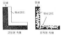
- FIG 3 is a schematic cross-sectional view of a conventional coated SCR catalyst and a deposited SCR catalyst according to the present invention.
- Figure 4 is a photograph of the catalytic active material distribution in the deposition type SCR catalyst according to the present invention.
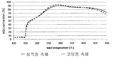
- FIG. 5 is a graph comparing the activity of the conventional SCR catalyst and the deposited SCR catalyst according to the present invention.
- the buried type SCR catalyst structure according to the present invention relates to a deposited type SCR catalyst structure in which a catalytically active material is deposited inside a carrier and substantially no catalytically active material is present on the inner wall of the carrier.
- deposit or “burying” means that the catalytically active material penetrates into the pores formed in the carrier and is supported in the pores, and the catalytically active material is not substantially coated on the inner wall of the carrier.
- the porosity of the pore charge volume in the total volume of the carrier is preferably 20% to 80%. If the porosity is 20% or less, it is not possible to provide sufficient catalytic function for the SCR reaction, and if it is 80% or more, the mechanical strength is lowered, and thus, a carrier having a porosity of 40 to 70%, more preferably 65% is preferable. .
- the carrier is preferably configured in a honeycomb form so that the pressure drop is minimized while the exhaust gas from the power plant or marine diesel engine passes through the catalyst.
- Honeycomb or honeycomb-shaped structures are obvious to those skilled in the art, but outlined, have parallel gas flow passages extending at the carrier inlet front or outlet back, which passages open at the front and rear, and at the gas inlet front. It has open passageways, ie channels, which are substantially straight paths to the discharge backside, which are formed by thin inner walls.
- the carrier according to the present invention is made of a ceramic material capable of providing the above-described high porosity, cordierite, silicon carbide, cordierite- ⁇ -alumina, silicon nitride, alumina-silica-magnesia, zircon silicate, silicate, It may be made of magnesium silicate, zircon, petalite, ⁇ -alumina, aluminosilicate and the like, and preferably made of cordierite.
- the catalytically active material is deposited in a plurality of pores formed in the carrier.
- the material deposited inside the carrier may be a vanadium-based, zeolite-based or base metal oxide in which titanium oxide (TiO 2 ), tungsten oxide (WO 3 ), or molybdenum oxide (MoO 3 ) is added to vanadium, but It is not limited.
- the immersion or buried SCR catalyst production method is quantified so that the catalytically active material does not exist on the inner wall of the carrier so that substantially all catalytically active material is deposited inside the carrier and the catalytically active material does not exist on the inner wall surface. It is manufactured so as not to be different from the conventional method for producing a coated SCR catalyst. That is, the conventional coated SCR catalyst quantifies the catalytically active slurry so that a thick coating layer is formed on the inner wall of the carrier, but the deposited SCR catalyst according to the present invention substantially catalyzes the catalytically active slurry so that all catalytically active materials penetrate into the carrier pores.
- the porous carrier is immersed in a slurry and then fired.
- the deposited SCR catalyst of the present invention (a) measuring the porosity of the carrier, (b) determining the amount of catalytically active slurry that can be deposited entirely in the carrier pores, (c) catalytically active slurry to the carrier It can easily be prepared by the step of depositing, and (d) calcining the catalyst obtained from step (c).
- the method for quantitative deposition in step (c) may be achieved by Korean Patent Application No. 10-2011-0098682 (catalytic support quantitative coating apparatus and method) filed on Sep. 29, 2011 by the present applicant, and the prior application. Is incorporated herein by reference.
- the extruded catalyst used in this evaluation was a honeycomb extruded catalyst structure (diameter 1 inch, length 2 inch, 50) whose main material was TiO 2 and WO 3 as refractory support material and V 2 O 5 as the denitrification oxide active material. cpi).
- the coating catalyst is a structure in which the refractory carrier is coated with the same catalytically active material (V 2 O 5 -TiO 2 -WO 3 ) on the inner wall of a cordierite honeycomb carrier (diameter 1 inch, length 2 inches, 50 cpi). to be.
- FIG. 1 shows the results of the structural change when the extruded and coated catalysts were contacted with water after exposure to sulfuric acid gas (24 hours).
- the catalyst structure gradually melts and almost collapses, whereas in the case of the coated catalyst, the carrier structure is maintained even when exposed to sulfuric acid gas, but the catalytically active material coated on the inner wall of the carrier is lost. It became.
- the conventional extruded or coated catalyst is not suitable for the ship diesel engine and the power plant exhaust gas treatment containing a large amount of sulfur.
- Figure 2 is a graph showing the results of the evaluation of the compressive strength effect by the sulfur component for the conventional extruded and coated SCR catalyst.
- the compressive strength was Measured.
- the extrusion type of the new product itself compared to the coating type, but the compressive strength is reduced significantly after the SO2 gas treatment or sulfuric acid gas treatment will ultimately collapse the catalyst structure.
- coating type there is no change in strength even in SO 2 gas treatment or sulfuric acid gas treatment, but as shown in the results of FIG. The mold needed to improve its structure.
- FIG. 3 is a schematic cross-sectional view of a coated SCR catalyst and a deposited SCR catalyst according to the present invention.
- the carrier applied in the present invention is a highly porous carrier capable of depositing substantially all catalytically active ingredients. Accordingly, as illustrated in FIG. 3, in the deposition type catalyst, the washcoat (catalytically active ingredient) is all deposited inside the carrier, and thus the washcoat is substantially not present on the inner wall of the carrier.
- the conventional coating catalyst uses a conventional refractory ceramic carrier so that the washcoat is applied to the inner wall of the carrier to a certain thickness. Therefore, the catalytically active component is deposited into the carrier pores to solve the problem of adhesion caused by the problem in the conventional coating catalyst. Furthermore, since the volume of exhaust gas flowing in the carrier channel is relatively increased compared to the coating catalyst, the back pressure is reduced, thereby improving the fuel efficiency of the engine.
- Figure 4 is a photograph of the catalytic active material distribution in the deposition type SCR catalyst according to the present invention when applying a cordierite carrier having a 65% porosity. From the left picture to the right picture, 100 g / L, 135 g / L and 212 g / L were applied as dry gain (D / G). In other words, when 100 g / L or 135 g / L of catalytically active component is applied to a cordierite carrier having a 65% porosity, most of the catalytic components substantially penetrate into the carrier pores so that there is substantially no catalytic component contributing to the activity on the surface. .
- the method for preparing a catalyst according to the present invention primarily comprises the steps of (a) measuring the porosity of the carrier, (b) determining the amount of catalytically active slurry that can be deposited entirely in the carrier pores, and (c) the catalytically active slurry as a carrier. By dipping in, and (d) calcining the catalyst obtained from step (c).
- the catalytically active component is 3% V 2 O 5 / TiO 2
- dry gain of 100g / L is deposited inside the carrier (300 cpsi) made of cordierite material having a porosity of 65%
- the catalytically active component is 2.5% V 2 O 5 / TiO 2
- the dry gain of 139.8 g / L is coated on the inner wall of the carrier (400 cpsi) made of cordierite material having a porosity of 35%.
- the activity evaluation conditions of both catalysts were space velocity (SV): 50,000 1 / hr, feed gas component: 500 ppm NO, 500 ppm NH 3 , 10% O 2 , 5% H 2 O, N 2 balance.
- SV space velocity
- feed gas component 500 ppm NO, 500 ppm NH 3 , 10% O 2 , 5% H 2 O, N 2 balance.
Landscapes
- Chemical & Material Sciences (AREA)
- Engineering & Computer Science (AREA)
- Chemical Kinetics & Catalysis (AREA)
- Organic Chemistry (AREA)
- Materials Engineering (AREA)
- Health & Medical Sciences (AREA)
- Environmental & Geological Engineering (AREA)
- General Chemical & Material Sciences (AREA)
- Oil, Petroleum & Natural Gas (AREA)
- Analytical Chemistry (AREA)
- Biomedical Technology (AREA)
- Combustion & Propulsion (AREA)
- Toxicology (AREA)
- Mechanical Engineering (AREA)
- General Engineering & Computer Science (AREA)
- Catalysts (AREA)
- Exhaust Gas Treatment By Means Of Catalyst (AREA)
Priority Applications (3)
| Application Number | Priority Date | Filing Date | Title |
|---|---|---|---|
| CN201380035836.9A CN104411403A (zh) | 2012-06-12 | 2013-06-07 | 载体空隙埋没型scr催化剂结构 |
| EP13803774.2A EP2859944A4 (en) | 2012-06-12 | 2013-06-07 | INCORPORATED SCR CATALYST STRUCTURE COMPRISING A CATALYST INCORPORATED IN THE PORES OF THE SUPPORT |
| JP2015517173A JP2015519199A (ja) | 2012-06-12 | 2013-06-07 | 担体空隙埋没型scr触媒構造体 |
Applications Claiming Priority (2)
| Application Number | Priority Date | Filing Date | Title |
|---|---|---|---|
| KR10-2012-0062412 | 2012-06-12 | ||
| KR20120062412A KR101336597B1 (ko) | 2012-06-12 | 2012-06-12 | 담체 공극 매몰형 scr 촉매 구조체 |
Publications (1)
| Publication Number | Publication Date |
|---|---|
| WO2013187632A1 true WO2013187632A1 (ko) | 2013-12-19 |
Family
ID=49758410
Family Applications (1)
| Application Number | Title | Priority Date | Filing Date |
|---|---|---|---|
| PCT/KR2013/005002 WO2013187632A1 (ko) | 2012-06-12 | 2013-06-07 | 담체 공극 매몰형 scr 촉매 구조체 |
Country Status (5)
| Country | Link |
|---|---|
| EP (1) | EP2859944A4 (ja) |
| JP (1) | JP2015519199A (ja) |
| KR (1) | KR101336597B1 (ja) |
| CN (1) | CN104411403A (ja) |
| WO (1) | WO2013187632A1 (ja) |
Cited By (2)
| Publication number | Priority date | Publication date | Assignee | Title |
|---|---|---|---|---|
| CN111036192A (zh) * | 2019-12-23 | 2020-04-21 | 中国科学院过程工程研究所 | 一种涂覆型耐磨钒系脱硝催化剂及其制备方法与应用 |
| JP2021000631A (ja) * | 2014-07-31 | 2021-01-07 | ジョンソン、マッセイ、パブリック、リミテッド、カンパニーJohnson Matthey Public Limited Company | 触媒を製造するための方法及び触媒物品 |
Families Citing this family (3)
| Publication number | Priority date | Publication date | Assignee | Title |
|---|---|---|---|---|
| JP6787935B2 (ja) * | 2015-06-18 | 2020-11-18 | ジョンソン、マッセイ、パブリック、リミテッド、カンパニーJohnson Matthey Public Limited Company | 単一層又は二層アンモニアスリップ触媒 |
| KR101765767B1 (ko) * | 2015-11-02 | 2017-08-07 | 희성촉매 주식회사 | 담체 계면 공극 집중 매몰형 scr 촉매 구조체 |
| WO2021041201A2 (en) * | 2019-08-23 | 2021-03-04 | Basf Corp. | Catalyst compositions and methods of preparation and use thereof |
Citations (6)
| Publication number | Priority date | Publication date | Assignee | Title |
|---|---|---|---|---|
| JP2001286767A (ja) * | 2000-04-07 | 2001-10-16 | Nissan Motor Co Ltd | 触媒構造体及びその製造方法 |
| JP2006116431A (ja) * | 2004-10-21 | 2006-05-11 | Toyota Motor Corp | 排気浄化触媒および排気浄化触媒の製造方法 |
| JP2007209898A (ja) * | 2006-02-09 | 2007-08-23 | Toyota Motor Corp | 排ガス浄化触媒 |
| JP2007268527A (ja) * | 2006-03-10 | 2007-10-18 | Nippon Shokubai Co Ltd | 排水処理用触媒及び該触媒を用いた排水の処理方法 |
| KR20090108109A (ko) * | 2007-01-31 | 2009-10-14 | 바스프 카탈리스트 엘엘씨 | 다공벽 벌집을 포함하는 기체 촉매 |
| KR20110098682A (ko) | 2010-02-26 | 2011-09-01 | 엔이씨 커뮤니케이션 시스템즈, 리미티드 | 발광 구동 조정 방법 및 시스템과 가시광 통신 장치 |
Family Cites Families (4)
| Publication number | Priority date | Publication date | Assignee | Title |
|---|---|---|---|---|
| EP0704241A1 (en) * | 1994-09-29 | 1996-04-03 | Corning Incorporated | Catalyst structure comprizing a cellular substrate and a layer of catalytically active material |
| DE102005062317B4 (de) * | 2005-12-24 | 2008-08-21 | Umicore Ag & Co. Kg | Verfahren zur katalytischen Beschichtung von keramischen Wabenkörpern |
| DE102007012928B4 (de) * | 2007-03-19 | 2009-09-03 | Umicore Ag & Co. Kg | Verfahren zur Einbringung einer katalytischen Beschichtung in die Poren eines keramischen Durchfluß-Wabenkörpers |
| JP2013043138A (ja) * | 2011-08-25 | 2013-03-04 | Denso Corp | 触媒担持体及びその製造方法 |
-
2012
- 2012-06-12 KR KR20120062412A patent/KR101336597B1/ko active IP Right Grant
-
2013
- 2013-06-07 CN CN201380035836.9A patent/CN104411403A/zh active Pending
- 2013-06-07 JP JP2015517173A patent/JP2015519199A/ja not_active Abandoned
- 2013-06-07 EP EP13803774.2A patent/EP2859944A4/en not_active Withdrawn
- 2013-06-07 WO PCT/KR2013/005002 patent/WO2013187632A1/ko active Application Filing
Patent Citations (6)
| Publication number | Priority date | Publication date | Assignee | Title |
|---|---|---|---|---|
| JP2001286767A (ja) * | 2000-04-07 | 2001-10-16 | Nissan Motor Co Ltd | 触媒構造体及びその製造方法 |
| JP2006116431A (ja) * | 2004-10-21 | 2006-05-11 | Toyota Motor Corp | 排気浄化触媒および排気浄化触媒の製造方法 |
| JP2007209898A (ja) * | 2006-02-09 | 2007-08-23 | Toyota Motor Corp | 排ガス浄化触媒 |
| JP2007268527A (ja) * | 2006-03-10 | 2007-10-18 | Nippon Shokubai Co Ltd | 排水処理用触媒及び該触媒を用いた排水の処理方法 |
| KR20090108109A (ko) * | 2007-01-31 | 2009-10-14 | 바스프 카탈리스트 엘엘씨 | 다공벽 벌집을 포함하는 기체 촉매 |
| KR20110098682A (ko) | 2010-02-26 | 2011-09-01 | 엔이씨 커뮤니케이션 시스템즈, 리미티드 | 발광 구동 조정 방법 및 시스템과 가시광 통신 장치 |
Non-Patent Citations (1)
| Title |
|---|
| See also references of EP2859944A4 |
Cited By (3)
| Publication number | Priority date | Publication date | Assignee | Title |
|---|---|---|---|---|
| JP2021000631A (ja) * | 2014-07-31 | 2021-01-07 | ジョンソン、マッセイ、パブリック、リミテッド、カンパニーJohnson Matthey Public Limited Company | 触媒を製造するための方法及び触媒物品 |
| CN111036192A (zh) * | 2019-12-23 | 2020-04-21 | 中国科学院过程工程研究所 | 一种涂覆型耐磨钒系脱硝催化剂及其制备方法与应用 |
| CN111036192B (zh) * | 2019-12-23 | 2021-08-06 | 中国科学院过程工程研究所 | 一种涂覆型耐磨钒系脱硝催化剂及其制备方法与应用 |
Also Published As
| Publication number | Publication date |
|---|---|
| JP2015519199A (ja) | 2015-07-09 |
| EP2859944A4 (en) | 2016-03-30 |
| EP2859944A1 (en) | 2015-04-15 |
| CN104411403A (zh) | 2015-03-11 |
| KR101336597B1 (ko) | 2013-12-16 |
Similar Documents
| Publication | Publication Date | Title |
|---|---|---|
| US8591820B2 (en) | Honeycomb filters for reducing NOx and particulate matter in diesel engine exhaust | |
| US10610830B2 (en) | Honeycomb structure | |
| WO2013187632A1 (ko) | 담체 공극 매몰형 scr 촉매 구조체 | |
| KR101868176B1 (ko) | 개선된 no 산화 활성을 갖는 가솔린 린번 엔진용 촉매 | |
| JP7422199B2 (ja) | 膜を有する触媒ウォールフロー型フィルター | |
| US20090118121A1 (en) | Exhaust Emission Control Catalyst and Exhaust Emission Control System | |
| US20040053781A1 (en) | Filter catalyst for purifying exhaust gases and its manufacturing method thereof | |
| KR20150023543A (ko) | 바나데이트를 포함하는 선택적 촉매 환원 벽유동형 필터 | |
| KR20150111979A (ko) | 암모니아 산화 촉매 | |
| JPWO2007094379A1 (ja) | ハニカム構造体及びハニカム触媒体 | |
| US10702855B2 (en) | Method of preparation of a monilithic catalyst for selective catalytic reduction of nitrogen oxides | |
| US11052378B2 (en) | Diesel oxidizing catalytic converter | |
| RU2693135C2 (ru) | Способ нанесения покрытия на корпус-подложку | |
| EP2889463B1 (en) | High performance scr catalyst system | |
| WO2019032409A1 (en) | SRC CATALYTIC COATING ON PARTICLE FILTERS | |
| KR20180088864A (ko) | 질소 산화물의 선택적 촉매 환원을 위한 모노리스 촉매의 제조방법 | |
| KR101765767B1 (ko) | 담체 계면 공극 집중 매몰형 scr 촉매 구조체 | |
| US10737258B2 (en) | Honeycomb catalyst for removal of nitrogen oxides in flue and exhaust gasses and method of preparation thereof | |
| US20230338938A1 (en) | Emission control catalyst article with enriched pgm zone, method and apparatus to produce the same |
Legal Events
| Date | Code | Title | Description |
|---|---|---|---|
| 121 | Ep: the epo has been informed by wipo that ep was designated in this application |
Ref document number: 13803774 Country of ref document: EP Kind code of ref document: A1 |
|
| ENP | Entry into the national phase |
Ref document number: 2015517173 Country of ref document: JP Kind code of ref document: A |
|
| NENP | Non-entry into the national phase |
Ref country code: DE |
|
| REEP | Request for entry into the european phase |
Ref document number: 2013803774 Country of ref document: EP |
|
| WWE | Wipo information: entry into national phase |
Ref document number: 2013803774 Country of ref document: EP |