WO2013183392A1 - 音声信号処理装置、音声信号処理方法およびコンピュータプログラム - Google Patents
音声信号処理装置、音声信号処理方法およびコンピュータプログラム Download PDFInfo
- Publication number
- WO2013183392A1 WO2013183392A1 PCT/JP2013/062849 JP2013062849W WO2013183392A1 WO 2013183392 A1 WO2013183392 A1 WO 2013183392A1 JP 2013062849 W JP2013062849 W JP 2013062849W WO 2013183392 A1 WO2013183392 A1 WO 2013183392A1
- Authority
- WO
- WIPO (PCT)
- Prior art keywords
- signal processing
- signal
- audio signal
- sound image
- channel
- Prior art date
- Legal status (The legal status is an assumption and is not a legal conclusion. Google has not performed a legal analysis and makes no representation as to the accuracy of the status listed.)
- Ceased
Links
Images


Classifications
-
- H—ELECTRICITY
- H04—ELECTRIC COMMUNICATION TECHNIQUE
- H04S—STEREOPHONIC SYSTEMS
- H04S5/00—Pseudo-stereo systems, e.g. in which additional channel signals are derived from monophonic signals by means of phase shifting, time delay or reverberation
- H04S5/02—Pseudo-stereo systems, e.g. in which additional channel signals are derived from monophonic signals by means of phase shifting, time delay or reverberation of the pseudo four-channel type, e.g. in which rear channel signals are derived from two-channel stereo signals
-
- H—ELECTRICITY
- H04—ELECTRIC COMMUNICATION TECHNIQUE
- H04S—STEREOPHONIC SYSTEMS
- H04S1/00—Two-channel systems
- H04S1/002—Non-adaptive circuits, e.g. manually adjustable or static, for enhancing the sound image or the spatial distribution
- H04S1/005—For headphones
-
- H—ELECTRICITY
- H04—ELECTRIC COMMUNICATION TECHNIQUE
- H04S—STEREOPHONIC SYSTEMS
- H04S2400/00—Details of stereophonic systems covered by H04S but not provided for in its groups
- H04S2400/03—Aspects of down-mixing multi-channel audio to configurations with lower numbers of playback channels, e.g. 7.1 -> 5.1
-
- H—ELECTRICITY
- H04—ELECTRIC COMMUNICATION TECHNIQUE
- H04S—STEREOPHONIC SYSTEMS
- H04S2420/00—Techniques used stereophonic systems covered by H04S but not provided for in its groups
- H04S2420/01—Enhancing the perception of the sound image or of the spatial distribution using head related transfer functions [HRTF's] or equivalents thereof, e.g. interaural time difference [ITD] or interaural level difference [ILD]
Definitions
- the present disclosure relates to an audio signal processing device, an audio signal processing method, and a computer program.
- the sound signal reproduced with the headphones is a normal sound signal supplied to the speakers installed on the front left and right of the listener. There may be. In such a case, it is known that a so-called localization phenomenon occurs in which the sound image reproduced by the headphones is trapped in the listener's head.
- Patent Literature 1 and Patent Literature 2 disclose a technique called virtual sound image localization as a solution to the problem of the localization in the head.
- This virtual sound image localization is reproduced as if a sound source, for example, a speaker, is present at a pre-estimated position, such as a left-right position in front of the listener, when reproduced with headphones or the like (virtual sound image localization is virtually performed at that position). To be localized).
- a speaker is arranged at the virtual sound image localization position of each channel, for example, an impulse is reproduced, and the head related transfer function for each channel is reproduced. Measure. Then, the impulse response of the head-related transfer function obtained by measurement may be convoluted with the audio signal supplied to the sound reproduction driver for the left and right channels of the headphones.
- multi-channel surround systems such as 5.1 channel, 7.1 channel, and 9.1 channel have been adopted for audio playback accompanying video playback recorded on an optical disc.
- sound image localization virtual sound image localization
- the present disclosure is a new and improved reproduction that can reproduce the sound quality and sound field when a speaker is actually placed and listened to when reproducing a multi-surround audio signal as a 2-channel audio signal.
- An audio signal processing device, an audio signal processing method, and a computer program are provided.
- a two-channel audio signal for sound reproduction is generated from two or more channels of audio signals greater than two channels by two electroacoustic conversion means installed in the vicinity of the listener's both ears.
- the virtual sound image localization position is provided on the circumference centered on the virtual sound image localization position assumed for each channel of the plurality of channels of audio signals provided on the circumference centered on the listener.
- An audio signal processing apparatus including a signal processing unit to be changed is provided.
- a two-channel audio signal for sound reproduction is generated from two or more channels of audio signals that are more than two channels by two electroacoustic conversion means installed near the listener's both ears. Output the virtual sound localization position on the circumference centered on the virtual sound localization position assumed for each channel of the plurality of channels of audio signals provided on the circumference centering on the listener.
- a two-channel audio signal that is reproduced by a computer from two or more channels of audio signals that are more than two channels by two electroacoustic conversion units installed in the vicinity of the listener's both ears. Is generated on the circumference centered on the listener, the virtual sound image localization position is set around the virtual sound image localization position assumed for each channel of the audio signals of the plurality of channels.
- a computer program is provided that causes the steps to vary on a circumference to be executed.
- a multi-surround audio signal is reproduced as a 2-channel audio signal, it is possible to reproduce the sound quality and sound field when the speaker is actually placed and listened to.
- a new and improved audio signal processing apparatus, audio signal processing method, and computer program can be provided.
- FIG. 2 is an explanatory diagram illustrating a configuration example of an audio signal processing device 10 according to an embodiment of the present disclosure.
- FIG. 2 is an explanatory diagram illustrating a configuration example of an audio signal processing device 10 according to an embodiment of the present disclosure.
- FIG. 3 is an explanatory diagram illustrating a configuration example of a signal processing unit 100.
- FIG. 3 is an explanatory diagram illustrating a configuration example of a signal processing unit 100.
- FIG. 3 is an explanatory diagram illustrating a configuration example of a signal processing unit 100.
- FIG. 3 is an explanatory diagram illustrating a configuration example of a signal processing unit 100.
- FIG. 3 is an explanatory diagram illustrating a configuration example of a signal processing unit 100.
- FIG. 3 is an explanatory diagram illustrating a configuration example of a signal processing unit 100.
- FIG. 3 is an explanatory diagram illustrating a configuration example of a signal processing unit 100.
- FIG. 3 is an explanatory diagram illustrating a configuration example of a signal processing unit 100.
- FIG. 5 is a flowchart illustrating an operation example of the audio signal processing device 10 according to an embodiment of the present disclosure. It is explanatory drawing which shows the example of a change of the parameter at the time of shaking an audio
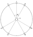
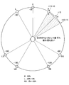
- FIG. 1 is an explanatory diagram showing a 7.1-channel multi-surround speaker arrangement example of ITU-R (International Telecommunication Union Radiocommunication Division) which is an example of multi-surround.
- ITU-R International Telecommunication Union Radiocommunication Division
- FIG. 1 is an explanatory diagram showing a 7.1-channel multi-surround speaker arrangement example of ITU-R (International Telecommunication Union Radiocommunication Division) which is an example of multi-surround.
- ITU-R International Telecommunication Union Radiocommunication Division
- ITU-R 7.1-channel multi-surround speaker arrangement example is determined such that the speakers of each channel are positioned on the circumference centered on the listener position Pn, as shown in FIG.
- C which is the front position of the listener Pn is the speaker position of the center channel.
- LF and RF which are positions separated from each other by an angular range of 60 degrees with respect to the speaker position C of the center channel, indicate the speaker positions of the left front channel and the right front channel, respectively.
- two speaker positions LS, LB and RS, RB are set on the left side and the right side in the range from 60 degrees to 150 degrees on the left and right of the front position C of the listener Pn.
- These speaker positions LS, LB and RS, RB are set at positions symmetrical to the listener.
- the speaker positions LS and RS are the speaker positions of the left side channel and the right side channel
- the speaker positions LB and RB are the speaker positions of the left rear channel and the right rear channel.
- an overhead phone in which one headphone driver is arranged for each of the left and right ears of the listener Pn.
- the 7.1-channel multi-surround audio signal when the 7.1-channel multi-surround audio signal is acoustically reproduced by the overhead phone of this example, the directions of the speaker positions C, LF, RF, LS, RS, LB, and RB in FIG. The sound is reproduced as the sound image localization direction. Therefore, as described later, the selected head-related transfer function is convolved with the audio signal of each channel of the 7.1-channel multi-surround audio signal.
- 7.1-channel multi-surround shown in FIG. 1 is assumed.
- the multi-surround of the present disclosure is not limited to the example.
- 5.1 channel multi-surround has a speaker arrangement in which the speakers located at speaker positions LB and RB are removed from the 7.1-channel multi-surround speaker arrangement shown in FIG.
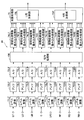
- FIGS. 2 and 3 are explanatory diagrams illustrating a configuration example of the audio signal processing device 10 according to an embodiment of the present disclosure.
- a configuration example of the audio signal processing device 10 according to an embodiment of the present disclosure will be described with reference to FIGS. 2 and 3.
- the electroacoustic conversion means for converting the electrical signal and delivering the sound to the ear of the listener Pn includes the headphone driver 120L for the left channel and the headphone driver 120R for the right channel.
- the headphone driver 120L for the left channel includes the headphone driver 120L for the left channel and the headphone driver 120R for the right channel.
- the audio signals of the respective channels to be supplied to the speaker positions C, LF, RF, LS, RS, LB, RB in FIG. 1 are the same symbols C, LF, RF, LS, It shows using RS, LB, RB.
- the LFE (Low Frequency Effect) channel is a low-frequency effect channel, which is usually a sound whose sound image localization direction is not determined.
- the audio channel is not subject to convolution.
- each of the 7.1-channel audio signals LF, LS, RF, RS, LB, RB, C, and LFE includes level adjusters 71LF, 71LS, 71RF, 71RS, 71LB, 71RB, 71C, The audio signal is supplied to 71LFE and the level of each audio signal is adjusted.
- the audio signals from the level adjusters 71LF, 71LS, 71RF, 71RS, 71LB, 71RB, 71C, 71LFE were amplified by predetermined amounts by the amplifiers 72LF, 72LS, 72RF, 72RS, 72LB, 72RB, 72C, 72LFE, respectively. Later, the signals are supplied to A / D converters 73LF, 73LS, 73RF, 73RS, 73LB, 73RB, 73C, 73LFE and converted into digital audio signals.
- the digital audio signals from the A / D converters 73LF, 73LS, 73RF, 73RS, 73LB, 73RB, 73C, and 73LFE are subjected to signal processing to be described later in the signal processing unit 100, respectively, and then subjected to head-related transfer function convolution. It is supplied to the processing units 74LF, 74LS, 74RF, 74RS, 74LB, 74RB, 74C, and 74LFE.
- each of the head related transfer function convolution processing units 74LF, 74LS, 74RF, 74RS, 74LB, 74RB, 74C, and 74LFE in this example, for example, a convolution method disclosed in Japanese Patent Application Laid-Open No. 2011-9842 is used. A convolution process of the head-related transfer function of the direct wave and the reflected wave is performed.
- each of the head related transfer function convolution processing units 74LF, 74LS, 74RF, 74RS, 74LB, 74RB, 74C, and 74LFE convolves the crosstalk component of each channel and the head related transfer function of the reflected wave.
- the convolution method disclosed in Japanese Patent Application Laid-Open No. 2011-9842 is performed in the same manner.
- the reflected wave to be processed is only one reflected wave for simplicity. did.
- the number of reflected waves to be processed is not limited to this example.
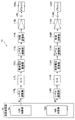
- the addition processing unit 75 includes a left channel addition unit (hereinafter referred to as “L addition unit”) 75L and a right channel addition unit (hereinafter referred to as “R addition unit”) 75R of 2-channel stereo headphones.
- L addition unit left channel addition unit
- R addition unit right channel addition unit
- the L adder 75L includes the original left channel components LF, LS, LB and their reflected wave components, the crosstalk components of the right channel components RF, RS, RB and their reflected components, the center channel component C, and the low frequency effect.
- the channel component LFE is added.
- the L addition unit 75L supplies the addition result to the D / A converter 111L through the level adjustment unit 110L as a synthesized audio signal SL for the headphone driver 120L for the left channel, as shown in FIG.
- the R adder 75R includes the original right channel components RF, RS, RB and the reflected wave components thereof, the crosstalk component of the left channel components LF, LS, LB and the reflected components thereof, the center channel component C, and the low frequency effect.
- the channel component LFE is added.
- the R addition unit 75R supplies the addition result to the D / A conversion unit 111R through the level adjustment unit 110R as a synthesized audio signal SR for the headphone driver 120R for the right channel, as shown in FIG. .
- the center channel component C and the low-frequency effect channel component LFE are supplied to both the L adder 75L and the R adder 75R, and are added to both the left channel and the right channel.
- the sound localization in the direction of the center channel can be improved, and the low-frequency audio component by the low-frequency effect channel component LFE can be reproduced with a wider spread.
- the left channel synthesized speech signal SL and the right channel synthesized speech signal SR in which the head-related transfer functions are convoluted are converted into analog speech signals as described above. .
- the analog audio signals from the D / A converters 111L and 111R are supplied to the current / voltage converters 112L and 112R, respectively, and converted from current signals to voltage signals.
- the audio signals converted into voltage signals from the current-voltage converters 112L and 112R are level-adjusted by the level adjusters 113L and 113R, and then supplied to the gain adjusters 114L and 114R, respectively. Gain is adjusted.
- the output audio signals of the gain adjusting units 114L and 114R are amplified by the amplifiers 115L and 115R, and then output to the output terminals 116L and 116R of the audio signal processing device of the embodiment.
- the audio signals derived to the output terminals 116L and 116R are respectively supplied to the headphone driver 120L for the left ear and the headphone driver 12R for the right ear, and are reproduced acoustically.
- the headphone driver reproduces the 7.1-channel multi-surround sound field by virtual sound image localization by the headphone drivers 120L and 120R for the left and right ears one by one. Can do.
- the signal processing unit 100 shown in FIG. 2 performs signal processing on each of the 7.1-channel audio signals LF, LS, RF, RS, LB, RB, and C.
- the signal processing unit 100 slightly mixes the audio signals of other channels with the 7.1-channel audio signals LF, LS, RF, RS, LB, RB, and C, and A process of slightly shaking the sound image is executed.
- the signal processing unit 100 performs signal processing on each of the 7.1-channel audio signals LF, LS, RF, RS, LB, RB, and C before convolution of the head-related transfer function, thereby generating audio.
- the signal processing apparatus 10 can improve the sound quality of the virtual surround sound and expand the sound field after the convolution signal processing and the mixing of the sound signals to be output to the two-channel stereo headphones.
- the configuration example of the audio signal processing device 10 according to the embodiment of the present disclosure has been described above with reference to FIGS. 2 and 3. Next, a configuration example of the signal processing unit 100 included in the audio signal processing device 10 according to an embodiment of the present disclosure will be described.
- FIGS. 4A to 4G are explanatory diagrams illustrating a configuration example of the signal processing unit 100 included in the audio signal processing device 10 according to an embodiment of the present disclosure.
- a configuration example of the signal processing unit 100 included in the audio signal processing device 10 according to the embodiment of the present disclosure will be described with reference to FIGS. 4A to 4G.
- FIG. 4A to 4G show examples of the configuration of the signal processing unit 100 for executing signal processing on each of the 7.1-channel audio signals LF, LS, RF, RS, LB, RB, and C.
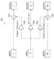
- FIG. 4A shows a configuration in which the above-described signal processing is performed for L of 7.1-channel audio signals.
- the signal processing unit 100 uses the L and R signals that are 30 degrees apart from each other when performing the above-described processing on the C signal. Further, the signal processing unit 100 uses the R signal 60 degrees to the right and the LS signal 90 degrees to the left when performing the above-described processing on the L signal. Similarly, when performing the above-described processing on the R signal, the signal processing unit 100 uses L that is 60 degrees away to the left and an RS signal that is 90 degrees to the right.
- the signal processing unit 100 uses the L signal 90 degrees to the right and the RS signal 120 degrees to the left when performing the above-described processing on the LS signal.
- the reason why the signal processing unit 100 uses the RB signal that is 120 degrees to the left instead of the RB signal that is 90 degrees to the left is that the RB signal does not exist in the 5.1 channel multi-surround. is there.
- the signal processing unit 100 uses the R signal 90 degrees to the left and the LS signal 120 degrees to the right when performing the above-described processing on the RS signal.
- the signal processor 100 uses the LS signal 120 degrees to the right instead of the LB signal 90 degrees to the right because the LB signal does not exist in 5.1 channel multi-surround. is there.
- the signal processing unit 100 uses the LS signal 30 degrees to the right and the RB signal 60 degrees to the left when performing the above-described processing on the LB signal.
- the signal processing unit 100 uses the RS signal 30 degrees to the left and the LB signal 60 degrees to the right when performing the above-described processing on the RB signal.
- the signal processing unit 100 performs a process of slightly shaking the sound image using the other two sound signals described above for each sound signal.
- the sound signal processing apparatus 10 can improve the sound quality and sound field when a multi-surround sound signal is reproduced as a two-channel sound signal.
- the signal processing unit 100 synchronizes fluctuations in the sound image for all channels. That is, the signal processing unit 100 swings the sound image localization position so as to perform the same movement for all channels. As a result, the audio signal processing apparatus 10 can reproduce the sound quality and sound field when a multi-surround speaker is actually placed and listened to.
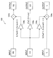
- FIG. 4A shows amplifiers 131a, 131b, and 131c and adders 131d and 131e.
- the amplifiers 131a, 131b, and 131c all amplify a predetermined amount of the L signal out of the 7.1 channel audio signal and output the amplified signal.
- the amplifier 131a amplifies the L signal by ⁇ f (1-2 ⁇ ⁇ f). As the values of ⁇ f and ⁇ f, those described later are used.
- the amplifier 131b amplifies the L signal by F_PanS * ⁇ f ( ⁇ f * ⁇ ).
- the amplifier 131c amplifies the L signal by F_PanF * ⁇ f ( ⁇ f * (1- ⁇ )).
- ⁇ ranges from 0 to 1, and is a value that changes in a predetermined cycle.
- the values of F_PanS and F_PanF will be described later.
- ⁇ f, ⁇ f, ⁇ , F_PanS, and F_PanF are parameters for swinging the virtual sound image localization position with respect to the L signal. The same applies to the following parameters.
- the adder 131d adds the LS signal to the L signal amplified by the amplifier 131b and outputs the result.
- the adder 131e adds the RS signal to the L signal amplified by the amplifier 131c and outputs the result.
- the signal amplified and added in this way by the signal processing unit 100 becomes a signal to be processed by convolving the head-related transfer function.
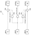
- FIG. 4B shows amplifiers 132a, 132b, and 132c, and adders 132d and 132e.
- the amplifiers 132a, 132b, and 132c all amplify the C signal out of the 7.1 channel audio signal and output the amplified signal.
- the amplifier 132a amplifies the C signal by ⁇ c (1-2 ⁇ ⁇ c). As the values of ⁇ c and ⁇ c, those described later are used.
- the amplifier 132b amplifies the C signal by ⁇ c ( ⁇ c * ⁇ ).
- the amplifier 132c amplifies the C signal by ⁇ c ( ⁇ c * (1- ⁇ )).
- the adder 132d adds the L signal to the C signal amplified by the amplifier 132b and outputs the result.
- the adder 132e adds the R signal to the C signal amplified by the amplifier 132c and outputs the result.
- the signal amplified and added in this way by the signal processing unit 100 becomes a signal to be processed by convolving the head-related transfer function.
- FIG. 4C shows amplifiers 133a, 133b, and 133c, and adders 133d and 133e.
- the amplifiers 133a, 133b, and 133c all amplify the R signal out of the 7.1-channel audio signal and output the amplified signal.
- the amplifier 133a amplifies the R signal by ⁇ f (1-2 ⁇ ⁇ f). As the values of ⁇ f and ⁇ f, those described later are used.
- the amplifier 133b amplifies the R signal by F_PanF * ⁇ f ( ⁇ f * ⁇ ).
- the amplifier 133c amplifies the R signal by F_PanS * ⁇ f ( ⁇ f * (1- ⁇ )).
- the adder 133d adds the L signal to the R signal amplified by the amplifier 133b and outputs the result.
- the adder 133e adds the RS signal to the R signal amplified by the amplifier 133c and outputs the result.
- the signal amplified and added in this way by the signal processing unit 100 becomes a signal to be processed by convolving the head-related transfer function.
- FIG. 4D shows amplifiers 134a, 134b, and 134c, and adders 134d and 134e.
- the amplifiers 134a, 134b, and 134c all amplify a predetermined amount of the LS signal out of the 7.1 channel audio signal and output the amplified signal.
- the amplifier 134a amplifies the LS signal by ⁇ s (1-2 ⁇ ⁇ s). As the values of ⁇ s and ⁇ s, those described later are used.
- the amplifier 134b amplifies the LS signal by S_PanS * ⁇ s ( ⁇ s * ⁇ ).
- the amplifier 134c amplifies the LS signal by S_PanF * ⁇ s ( ⁇ s * (1- ⁇ )).
- the adder 134d adds the RS signal to the LS signal amplified by the amplifier 134b and outputs the result.
- the adder 134e adds the L signal to the LS signal amplified by the amplifier 134c and outputs the result.
- the signal amplified and added in this way by the signal processing unit 100 becomes a signal to be processed by convolving the head-related transfer function.
- FIG. 4E shows amplifiers 135a, 135b, and 135c and adders 135d and 135e.
- the amplifiers 135a, 135b, and 135c all amplify the RS signal out of the 7.1 channel audio signal and output the amplified signal.
- the amplifier 135a amplifies the RS signal by ⁇ s (1-2 ⁇ ⁇ s). As the values of ⁇ s and ⁇ s, those described later are used.
- the amplifier 135b amplifies the RS signal by S_PanF * ⁇ s ( ⁇ s * ⁇ ).
- the amplifier 135c amplifies the RS signal by S_PanS * ⁇ s ( ⁇ s * (1- ⁇ )).
- the adder 135d adds the R signal to the RS signal amplified by the amplifier 135b and outputs the result.
- the adder 135e adds the LS signal to the RS signal amplified by the amplifier 135c and outputs the result.
- the signal amplified and added in this way by the signal processing unit 100 becomes a signal to be processed by convolving the head-related transfer function.
- FIG. 4F illustrates amplifiers 136a, 136b, and 136c and adders 136d and 136e.
- the amplifiers 136a, 136b, and 136c all amplify a predetermined amount of the LB signal out of the 7.1 channel audio signal and output the amplified signal.
- the amplifier 136a amplifies the signal of LB by ⁇ b (1-2 ⁇ ⁇ b). As the values of ⁇ b and ⁇ b, those described later are used.
- the amplifier 136b amplifies the signal of LB by B_PanS * ⁇ b ( ⁇ b * ⁇ ).
- the amplifier 136c amplifies the LB signal by B_PanB * ⁇ b ( ⁇ b * (1- ⁇ )).
- the adder 136d adds the LS signal to the LB signal amplified by the amplifier 136b and outputs the result.
- the adder 136e adds the RB signal to the LB signal amplified by the amplifier 136c and outputs the result.
- the signal amplified and added in this way by the signal processing unit 100 becomes a signal to be processed by convolving the head-related transfer function.
- FIG. 4G shows amplifiers 137a, 137b, and 137c and adders 137d and 137e.
- the amplifiers 137a, 137b, and 137c all amplify a predetermined amount of the RB signal out of the 7.1-channel audio signal and output the amplified signal.
- the amplifier 137a amplifies the RB signal by ⁇ b (1-2 ⁇ ⁇ b). As the values of ⁇ b and ⁇ b, those described later are used.
- the amplifier 137b amplifies the signal RB by B_PanB * ⁇ b ( ⁇ b * ⁇ ).
- the amplifier 137c amplifies B_PanS * ⁇ b ( ⁇ b * (1- ⁇ )) for the RB signal.
- the adder 137d adds the LB signal to the RB signal amplified by the amplifier 137b and outputs the result.
- the adder 137e adds the RS signal to the RB signal amplified by the amplifier 137c and outputs the result.
- the signal amplified and added in this way by the signal processing unit 100 becomes a signal to be processed by convolving the head-related transfer function.
- the above parameters are based on the distribution of the C signal and assume that each input signal fluctuates with the same sound image. For the channels other than the C signal, correction is performed according to the angle of the speaker to which each channel is distributed.
- F_PanF, F_PanS, S_PanF, S_PanS, B_PanS, and B_PanB relate to signals that cannot be distributed at the same angle, and are parameters for performing angle correction including correction by listening at the time of distribution. A method of distributing signals that cannot be distributed at the same angle will be described in detail later.
- F_Pan ⁇ 0.05 F_PanF (1.0 + F_Pan)
- F_PanS (1.0 ⁇ F_Pan)
- S_Pan (F_Pan * (150.0 / 210.0))
- S_PanF (1.0 + S_Pan)
- S_PanS (1.0 ⁇ S_Pan)
- B_Pan (F_Pan * (150.0 / 90.0))
- B_PanS (1.0 + B_Pan)
- B_PanB (1.0 ⁇ B_Pan)
- the audio signal processing apparatus 10 improves the sound quality of the virtual surround sound after the convolution signal processing and the mixing of the audio signals to be output to the two-channel stereo headphones. And the sound field can be expanded.
- the respective audio signals distributed in this way are periodically distributed in the range of ⁇ from 0 to 1 so that the same rotation is made according to the same speaker arrangement according to ⁇ .
- Examples of the period of ⁇ include a fixed pattern and a randomly distributed pattern. This pattern will be described later.
- the configuration example of the signal processing unit 100 included in the audio signal processing device 10 according to the embodiment of the present disclosure has been described above with reference to FIGS. 4A to 4G. Next, the operation of the audio signal processing device 10 according to an embodiment of the present disclosure will be described.
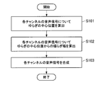
- FIG. 5 is a flowchart illustrating an operation example of the audio signal processing device 10 according to an embodiment of the present disclosure.
- the flowchart shown in FIG. 5 shows an operation example of the audio signal processing apparatus 10 when an operation for controlling the localization position of a sound image is performed on a multi-surround audio signal.
- an operation example of the audio signal processing device 10 according to the embodiment of the present disclosure will be described with reference to FIG.
- the signal processing unit 100 calculates the fluctuation center position for the audio signal of each channel of the multi-surround system (step S101).
- step S101 when the fluctuation center position is calculated for the audio signal of each channel, the signal processing unit 100 calculates the fluctuation width from the obtained fluctuation center position for the audio signal of each channel (step S101).
- step S102 The signal processing unit 100 sways the audio signal of each channel according to the fluctuation width calculated in step S102, and then synthesizes the audio signal of each channel with the audio signal of another channel (step S103).
- the signal processing unit 100 may change the parameter ⁇ in a cycle in the vicinity of the block size when compressing audio data that is difficult to be detected by the human ear. Further, the signal processing unit 100 may change the parameter ⁇ with a random period. Then, the signal processing unit 100 may perform control so that the audio signal of each channel is fluctuated by using multiple additions of the parameter ⁇ changed at different periods.
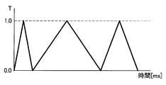
- FIG. 6A and 6B are explanatory diagrams illustrating an example of a change in the parameter ⁇ when the audio signal is shaken.
- FIG. 6A is a graph showing a change example when the parameter ⁇ is periodically changed.
- the parameter ⁇ is directly proportional to time with a period of 40 milliseconds.
- FIG. 6B shows a graph showing a change example when the parameter ⁇ is changed in a random cycle.
- the pattern in which the parameter ⁇ is changed randomly as shown in FIG. 6B is an improvement effect by adding multiple random noises of ⁇ 1 to +1 with different periods rather than changing with simple white noise (or M series). Becomes bigger.
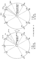
- FIG. 7 is an explanatory diagram showing the fluctuation width of the C signal.
- the C signal is distributed and distributed to an L signal and an R signal at equal intervals on the left and right.
- the distribution amount is 80% for C and 0 to 20% for L and R.
- the position of the sound image localization by the C signal fluctuates in the range of 6 degrees to the left and right around the position of the sound image localization by the original C signal. That is, the relationship between ⁇ c and ⁇ c in the above parameters is approximately 10 times within the range of 6 degrees, which is 1/10 of the interval of 60 degrees between L and R, and the position of the sound image localization by the C signal. Is to shake the left and right.
- FIG. 8 is an explanatory diagram showing the fluctuation width of the R signal.
- the R signal is distributed and distributed to the L signal and the RS signal that are not located at equal intervals on the left and right. Therefore, in order to distribute the R signal, first, the R position is temporarily set at a position where the L position and the RS position are equally spaced.
- the temporarily set position R is R ′.
- the position of R ′ is shifted to the right by 15 degrees from the position of R.
- the position of the sound image localization by the R 'signal is the R' signal. It fluctuates in the range of 15 degrees left and right around the position of the sound image localization by. In this case, the fluctuation width is too large and does not fluctuate in the same way as the C signal. Accordingly, as in the case of the C signal, the fluctuation width of the sound image localization position by the R signal is adjusted so that the fluctuation width is in the range of 6 degrees on the left and right.
- FIG. 9 is an explanatory diagram showing the fluctuation width of the R signal.
- FIG. 9 shows a method of adjusting the fluctuation width of the sound image localization position by the R signal from 15 degrees to 6 degrees.
- R is 80% and L and RS are allocated in the range of 0-20% respectively, so that the swing width is 6 degrees, R is 92%, and L and RS are each 0-8% in width. Change to sort. This is a value obtained by multiplying 20% allocated to L and RS by 60/150.
- the position of R ′ and the positions of L and RS to which the R signal is distributed are also R ′ as shown on the right side of FIG. , L ′ and RS ′.
- the fluctuation width is the same as that of the C signal, but the sound image localization position of the R signal is shifted to the right by 6 degrees from the original position. Therefore, the sound image localization position is adjusted to the original position. Need to be included.
- FIG. 10 is an explanatory diagram showing the fluctuation width of the R signal.
- FIG. 10 shows a method for adjusting the sound image localization position of the R signal to the original position.
- the positions of L ′ and RS ′ are also shifted to the left by 6 degrees.
- the positions of R ′, L ′, and RS ′ are changed to the positions of R ′′, L ′′, and RS ′′.
- the position of R ′′ is the same position as the position of R.
- the fluctuation width of the sound image localization position by the R signal is changed to the fluctuation width of the sound image localization position by the C signal. It can be adjusted by 6 degrees left and right.
- Parameters for adjusting the deflection are ⁇ f, ⁇ f, F_PanF, and F_PanS among the parameters described above. By setting ⁇ f, ⁇ f, F_PanF, and F_PanS to the above-described values, the fluctuation width of the sound image localization position by the R signal can be adjusted by 6 degrees on the left and right.
- the amplitude of other signals can be adjusted by 6 degrees to the left and right, which is the same as the amplitude of the sound image localization position by the C signal.
- FIG. 11 is an explanatory diagram showing the fluctuation width of the RS signal.
- the RS signal is also distributed and distributed to an R signal and an LS signal that are not equidistant on the left and right. Therefore, the shake width of the sound image localization position by the RS signal is adjusted by 6 degrees to the left and right by the same procedure as that for the R signal described above.
- the sound image localization position based on the RS signal is provisionally set so that R and LS are positioned at equal intervals, and the distribution amount is adjusted so that the fluctuation width is 6 degrees around the temporary sound image localization position.
- the fluctuation width of the sound image localization position by the RS signal is adjusted by 6 degrees on the left and right.
- Parameters for adjusting the fluctuation width of the sound image localization position based on the RS signal are ⁇ s, ⁇ s, S_PanF, and S_PanS among the parameters described above.
- FIG. 12 is an explanatory diagram showing the fluctuation width of the RB signal.
- the RB signal is also distributed and distributed to an RS signal and an LB signal that are not equidistant on the left and right. Therefore, the shake width of the sound image localization position by the RB signal is adjusted by 6 degrees to the left and right by the same procedure as that for the R signal described above. That is, the sound image localization position based on the RB signal is temporarily set so that RS and LB are positioned at equal intervals, and the distribution amount is adjusted so that the fluctuation width is 6 degrees around the temporary sound image localization position.
- the fluctuation width of the sound image localization position based on the RB signal is adjusted by 6 degrees on the left and right.
- Parameters for adjusting the fluctuation width of the sound image localization position based on the RB signal are ⁇ b, ⁇ b, B_PanB, and B_PanS among the above-described parameters.
- the amplitude can be adjusted by the same procedure as that for the RB signal.
- the sound signal processing apparatus 10 is output to the convolution signal processing or the two-channel stereo headphones by swinging the sound image localization position with the same amplitude for all the sound signals. Therefore, it is possible to improve the sound quality of the virtual surround sound after mixing the sound signals to be performed. Furthermore, the sound signal processing device 10 according to the embodiment of the present disclosure can be used for convolution signal processing or two-channel stereo headphones by swinging the sound image localization position with the same amplitude and the same timing for all sound signals. The sound quality of the virtual surround sound can be improved and the sound field can be expanded after mixing the sound signals to be output to the sound source.
- the audio signal processing apparatus 10 has a desired virtual sound image localization feeling when listening to virtual surround sound with two-channel stereo headphones by convolution of the head-related transfer function. can get. And the audio
- the audio signal processing device 10 performs signal processing for swinging the sound image localization position by each audio signal prior to convolution of the head-related transfer function, thereby performing 2-channel stereo headphones.
- the sound quality of the virtual surround sound can be improved and the sound field can be expanded after mixing the sound signals to be output to the sound source.
- the audio signal processing apparatus 10 swings the sound image localization position by signal processing. Therefore, even if a sensor for detecting the shaking of the listener's head is not required, the virtual surround sound The sound quality can be improved and the sound field can be expanded. Therefore, even when sound is output using existing headphones, the sound quality of the virtual surround sound can be improved and the sound field can be expanded by using the sound signal processing device 10 according to the embodiment of the present disclosure.
- the head related transfer function can be convolved according to a desired arbitrary listening environment or room environment, and a desired virtual sound image localization feeling can be obtained. Therefore, a head-related transfer function that removes the characteristics of the measurement microphone and the measurement speaker was used.
- the present disclosure is not limited to the case where such a special head-related transfer function is used, and can be applied even when a general head-related transfer function is convoluted.
- each step in the processing executed by each device in this specification does not necessarily have to be processed in chronological order in the order described as a sequence diagram or flowchart.
- each step in the processing executed by each device may be processed in an order different from the order described as the flowchart, or may be processed in parallel.
- this technique can also take the following structures.
- a signal processing unit provided on a circumference centered on a listener and configured to change the virtual sound image localization position on the circumference around a virtual sound image localization position assumed for each channel of the audio signals of the plurality of channels;
- An audio signal processing apparatus An audio signal processing apparatus.
- the audio signal processing device changes the virtual sound image localization position on the circumference in a cycle in which random noises having different cycles are added in a multiple manner so as to approximate a normal distribution.
- the audio signal processing device changes the virtual sound image localization position on the circumference in a cycle in which two random noises having different cycles are added.
- the signal processing unit is configured to convert the head-related transfer function for listening to a sound image so that the sound image is localized at the virtual sound image localization position before convolution with the audio signal of each channel of the plurality of channels.
- the audio signal processing device according to any one of (1) to (8), wherein: (10) When generating and outputting a two-channel audio signal to be reproduced by two electroacoustic conversion means installed at positions near the listener's both ears from a plurality of audio signals of more than two channels, A step of changing the virtual sound image localization position on the circumference around a virtual sound image localization position assumed for each channel of the plurality of channels of audio signals provided on a circumference centered on a listener; Audio signal processing method.
Landscapes
- Physics & Mathematics (AREA)
- Engineering & Computer Science (AREA)
- Acoustics & Sound (AREA)
- Signal Processing (AREA)
- Stereophonic System (AREA)
Priority Applications (6)
| Application Number | Priority Date | Filing Date | Title |
|---|---|---|---|
| JP2014519888A JP6225901B2 (ja) | 2012-06-06 | 2013-05-07 | 音声信号処理装置、音声信号処理方法およびコンピュータプログラム |
| US14/395,548 US9706326B2 (en) | 2012-06-06 | 2013-05-07 | Audio signal processing device, audio signal processing method, and computer program |
| CN201380028215.8A CN104335605B (zh) | 2012-06-06 | 2013-05-07 | 音频信号处理装置、音频信号处理方法和计算机程序 |
| BR112014029916A BR112014029916A2 (pt) | 2012-06-06 | 2013-05-07 | dispositivo e, método de processamento do sinal de áudio, e, programa de computador. |
| IN2340MUN2014 IN2014MN02340A (https=) | 2012-06-06 | 2013-05-07 | |
| EP13800983.2A EP2860993B1 (en) | 2012-06-06 | 2013-05-07 | Audio signal processing device, audio signal processing method, and computer program |
Applications Claiming Priority (2)
| Application Number | Priority Date | Filing Date | Title |
|---|---|---|---|
| JP2012128989 | 2012-06-06 | ||
| JP2012-128989 | 2012-06-06 |
Publications (1)
| Publication Number | Publication Date |
|---|---|
| WO2013183392A1 true WO2013183392A1 (ja) | 2013-12-12 |
Family
ID=49711793
Family Applications (1)
| Application Number | Title | Priority Date | Filing Date |
|---|---|---|---|
| PCT/JP2013/062849 Ceased WO2013183392A1 (ja) | 2012-06-06 | 2013-05-07 | 音声信号処理装置、音声信号処理方法およびコンピュータプログラム |
Country Status (7)
| Country | Link |
|---|---|
| US (1) | US9706326B2 (https=) |
| EP (1) | EP2860993B1 (https=) |
| JP (1) | JP6225901B2 (https=) |
| CN (1) | CN104335605B (https=) |
| BR (1) | BR112014029916A2 (https=) |
| IN (1) | IN2014MN02340A (https=) |
| WO (1) | WO2013183392A1 (https=) |
Cited By (1)
| Publication number | Priority date | Publication date | Assignee | Title |
|---|---|---|---|---|
| CN112119646A (zh) * | 2018-05-22 | 2020-12-22 | 索尼公司 | 信息处理装置、信息处理方法以及程序 |
Families Citing this family (4)
| Publication number | Priority date | Publication date | Assignee | Title |
|---|---|---|---|---|
| CN106535059B (zh) * | 2015-09-14 | 2018-05-08 | 中国移动通信集团公司 | 重建立体声的方法和音箱及位置信息处理方法和拾音器 |
| CN106255031B (zh) * | 2016-07-26 | 2018-01-30 | 北京地平线信息技术有限公司 | 虚拟声场产生装置和虚拟声场产生方法 |
| CN115379357B (zh) * | 2021-05-21 | 2025-03-28 | 上海艾为电子技术股份有限公司 | 一种振膜控制电路、振膜控制方法、芯片及电子设备 |
| CN116634060B (zh) * | 2022-02-10 | 2025-05-06 | 北京小米移动软件有限公司 | 终端设备及其发声控制方法、发声控制装置以及存储介质 |
Citations (6)
| Publication number | Priority date | Publication date | Assignee | Title |
|---|---|---|---|---|
| JPH03214897A (ja) | 1990-01-19 | 1991-09-20 | Sony Corp | 音響信号再生装置 |
| WO1995013690A1 (en) | 1993-11-08 | 1995-05-18 | Sony Corporation | Angle detector and audio playback apparatus using the detector |
| JP2007214815A (ja) * | 2006-02-08 | 2007-08-23 | Nagaoka Univ Of Technology | 頭外音像定位装置 |
| JP2009212944A (ja) * | 2008-03-05 | 2009-09-17 | Yamaha Corp | 音響装置 |
| JP2011009842A (ja) | 2009-06-23 | 2011-01-13 | Sony Corp | 音声信号処理装置および音声信号処理方法 |
| JP2012506673A (ja) * | 2008-10-20 | 2012-03-15 | ジェノーディオ,インコーポレーテッド | オーディオ空間化および環境シミュレーション |
Family Cites Families (4)
| Publication number | Priority date | Publication date | Assignee | Title |
|---|---|---|---|---|
| US4188504A (en) * | 1977-04-25 | 1980-02-12 | Victor Company Of Japan, Limited | Signal processing circuit for binaural signals |
| DE602006016017D1 (de) * | 2006-01-09 | 2010-09-16 | Nokia Corp | Steuerung der dekodierung binauraler audiosignale |
| US7876904B2 (en) * | 2006-07-08 | 2011-01-25 | Nokia Corporation | Dynamic decoding of binaural audio signals |
| JP2009206691A (ja) * | 2008-02-27 | 2009-09-10 | Sony Corp | 頭部伝達関数畳み込み方法および頭部伝達関数畳み込み装置 |
-
2013
- 2013-05-07 US US14/395,548 patent/US9706326B2/en not_active Expired - Fee Related
- 2013-05-07 BR BR112014029916A patent/BR112014029916A2/pt not_active Application Discontinuation
- 2013-05-07 JP JP2014519888A patent/JP6225901B2/ja not_active Expired - Fee Related
- 2013-05-07 CN CN201380028215.8A patent/CN104335605B/zh not_active Expired - Fee Related
- 2013-05-07 WO PCT/JP2013/062849 patent/WO2013183392A1/ja not_active Ceased
- 2013-05-07 EP EP13800983.2A patent/EP2860993B1/en active Active
- 2013-05-07 IN IN2340MUN2014 patent/IN2014MN02340A/en unknown
Patent Citations (6)
| Publication number | Priority date | Publication date | Assignee | Title |
|---|---|---|---|---|
| JPH03214897A (ja) | 1990-01-19 | 1991-09-20 | Sony Corp | 音響信号再生装置 |
| WO1995013690A1 (en) | 1993-11-08 | 1995-05-18 | Sony Corporation | Angle detector and audio playback apparatus using the detector |
| JP2007214815A (ja) * | 2006-02-08 | 2007-08-23 | Nagaoka Univ Of Technology | 頭外音像定位装置 |
| JP2009212944A (ja) * | 2008-03-05 | 2009-09-17 | Yamaha Corp | 音響装置 |
| JP2012506673A (ja) * | 2008-10-20 | 2012-03-15 | ジェノーディオ,インコーポレーテッド | オーディオ空間化および環境シミュレーション |
| JP2011009842A (ja) | 2009-06-23 | 2011-01-13 | Sony Corp | 音声信号処理装置および音声信号処理方法 |
Non-Patent Citations (1)
| Title |
|---|
| See also references of EP2860993A4 |
Cited By (3)
| Publication number | Priority date | Publication date | Assignee | Title |
|---|---|---|---|---|
| CN112119646A (zh) * | 2018-05-22 | 2020-12-22 | 索尼公司 | 信息处理装置、信息处理方法以及程序 |
| CN112119646B (zh) * | 2018-05-22 | 2022-09-06 | 索尼公司 | 信息处理装置、信息处理方法以及计算机可读存储介质 |
| US11463836B2 (en) | 2018-05-22 | 2022-10-04 | Sony Corporation | Information processing apparatus and information processing method |
Also Published As
| Publication number | Publication date |
|---|---|
| CN104335605B (zh) | 2017-10-03 |
| EP2860993A1 (en) | 2015-04-15 |
| CN104335605A (zh) | 2015-02-04 |
| EP2860993A4 (en) | 2015-12-02 |
| JP6225901B2 (ja) | 2017-11-08 |
| US9706326B2 (en) | 2017-07-11 |
| EP2860993B1 (en) | 2019-07-24 |
| JPWO2013183392A1 (ja) | 2016-01-28 |
| US20150117648A1 (en) | 2015-04-30 |
| BR112014029916A2 (pt) | 2018-04-17 |
| IN2014MN02340A (https=) | 2015-08-14 |
Similar Documents
| Publication | Publication Date | Title |
|---|---|---|
| JP5540581B2 (ja) | 音声信号処理装置および音声信号処理方法 | |
| US8477951B2 (en) | Front surround system and method of reproducing sound using psychoacoustic models | |
| FI113147B (fi) | Menetelmä ja signaalinkäsittelylaite stereosignaalien muuntamiseksi kuulokekuuntelua varten | |
| FI118370B (fi) | Stereolaajennusverkon ulostulon ekvalisointi | |
| CA2543614C (en) | Multi-channel audio surround sound from front located loudspeakers | |
| KR100608025B1 (ko) | 2채널 헤드폰용 입체 음향 생성 방법 및 장치 | |
| JP6102179B2 (ja) | 音声処理装置および方法、並びにプログラム | |
| US9607622B2 (en) | Audio-signal processing device, audio-signal processing method, program, and recording medium | |
| US10104470B2 (en) | Audio processing device, audio processing method, recording medium, and program | |
| JP2011205684A (ja) | 家庭および自動車聴取のためのディスクリートサラウンド音響システム | |
| EP2229012B1 (en) | Device, method, program, and system for canceling crosstalk when reproducing sound through plurality of speakers arranged around listener | |
| JP6225901B2 (ja) | 音声信号処理装置、音声信号処理方法およびコンピュータプログラム | |
| WO2012144227A1 (ja) | 音声信号再生装置、音声信号再生方法 | |
| US20200059750A1 (en) | Sound spatialization method | |
| EP2134108B1 (en) | Sound processing device, speaker apparatus, and sound processing method | |
| US8009834B2 (en) | Sound reproduction apparatus and method of enhancing low frequency component | |
| JP6512767B2 (ja) | 音響処理装置および方法、並びにプログラム | |
| US11388538B2 (en) | Signal processing device, signal processing method, and program for stabilizing localization of a sound image in a center direction | |
| JPH1014000A (ja) | 音響再生装置 | |
| JP2007336080A (ja) | 音響補正装置 | |
| JP2007202021A (ja) | 音声信号処理装置、音声信号処理システム、プログラム | |
| JPH08205297A (ja) | サラウンド信号処理装置 | |
| JPH06233394A (ja) | サラウンド信号処理装置 | |
| JP2008011099A (ja) | ヘッドフォン音響再生システム、ヘッドフォン装置 | |
| JP2018101824A (ja) | マルチチャンネル音響の音声信号変換装置及びそのプログラム |
Legal Events
| Date | Code | Title | Description |
|---|---|---|---|
| 121 | Ep: the epo has been informed by wipo that ep was designated in this application |
Ref document number: 13800983 Country of ref document: EP Kind code of ref document: A1 |
|
| WWE | Wipo information: entry into national phase |
Ref document number: 14395548 Country of ref document: US Ref document number: 2013800983 Country of ref document: EP |
|
| ENP | Entry into the national phase |
Ref document number: 2014519888 Country of ref document: JP Kind code of ref document: A |
|
| ENP | Entry into the national phase |
Ref document number: 2014148132 Country of ref document: RU Kind code of ref document: A |
|
| NENP | Non-entry into the national phase |
Ref country code: DE |
|
| REG | Reference to national code |
Ref country code: BR Ref legal event code: B01A Ref document number: 112014029916 Country of ref document: BR |
|
| ENP | Entry into the national phase |
Ref document number: 112014029916 Country of ref document: BR Kind code of ref document: A2 Effective date: 20141128 |