WO2013183200A1 - 高周波加熱装置 - Google Patents
高周波加熱装置 Download PDFInfo
- Publication number
- WO2013183200A1 WO2013183200A1 PCT/JP2013/001231 JP2013001231W WO2013183200A1 WO 2013183200 A1 WO2013183200 A1 WO 2013183200A1 JP 2013001231 W JP2013001231 W JP 2013001231W WO 2013183200 A1 WO2013183200 A1 WO 2013183200A1
- Authority
- WO
- WIPO (PCT)
- Prior art keywords
- unit
- frequency
- power
- frequency power
- modulation signal
- Prior art date
Links
Images


Classifications
-
- H—ELECTRICITY
- H05—ELECTRIC TECHNIQUES NOT OTHERWISE PROVIDED FOR
- H05B—ELECTRIC HEATING; ELECTRIC LIGHT SOURCES NOT OTHERWISE PROVIDED FOR; CIRCUIT ARRANGEMENTS FOR ELECTRIC LIGHT SOURCES, IN GENERAL
- H05B6/00—Heating by electric, magnetic or electromagnetic fields
- H05B6/02—Induction heating
- H05B6/06—Control, e.g. of temperature, of power
-
- H—ELECTRICITY
- H05—ELECTRIC TECHNIQUES NOT OTHERWISE PROVIDED FOR
- H05B—ELECTRIC HEATING; ELECTRIC LIGHT SOURCES NOT OTHERWISE PROVIDED FOR; CIRCUIT ARRANGEMENTS FOR ELECTRIC LIGHT SOURCES, IN GENERAL
- H05B6/00—Heating by electric, magnetic or electromagnetic fields
- H05B6/64—Heating using microwaves
- H05B6/66—Circuits
- H05B6/68—Circuits for monitoring or control
- H05B6/686—Circuits comprising a signal generator and power amplifier, e.g. using solid state oscillators
-
- H—ELECTRICITY
- H05—ELECTRIC TECHNIQUES NOT OTHERWISE PROVIDED FOR
- H05B—ELECTRIC HEATING; ELECTRIC LIGHT SOURCES NOT OTHERWISE PROVIDED FOR; CIRCUIT ARRANGEMENTS FOR ELECTRIC LIGHT SOURCES, IN GENERAL
- H05B6/00—Heating by electric, magnetic or electromagnetic fields
- H05B6/64—Heating using microwaves
- H05B6/70—Feed lines
- H05B6/705—Feed lines using microwave tuning
-
- Y—GENERAL TAGGING OF NEW TECHNOLOGICAL DEVELOPMENTS; GENERAL TAGGING OF CROSS-SECTIONAL TECHNOLOGIES SPANNING OVER SEVERAL SECTIONS OF THE IPC; TECHNICAL SUBJECTS COVERED BY FORMER USPC CROSS-REFERENCE ART COLLECTIONS [XRACs] AND DIGESTS
- Y02—TECHNOLOGIES OR APPLICATIONS FOR MITIGATION OR ADAPTATION AGAINST CLIMATE CHANGE
- Y02B—CLIMATE CHANGE MITIGATION TECHNOLOGIES RELATED TO BUILDINGS, e.g. HOUSING, HOUSE APPLIANCES OR RELATED END-USER APPLICATIONS
- Y02B40/00—Technologies aiming at improving the efficiency of home appliances, e.g. induction cooking or efficient technologies for refrigerators, freezers or dish washers
Definitions
- the present invention relates to a high-frequency heating device that dielectrically heats an object to be heated housed in a heating chamber.
- a local treatment according to the state and shape of the heated object has been conventionally performed.
- Various techniques for heating and stirring high-frequency power radiation into a heating chamber and irradiating an object to be heated are disclosed.
- Patent Document 1 discloses a technique for manipulating a microwave distribution by controlling the phase difference between power feeding portions arranged substantially symmetrically on the bottom wall surface of a heating chamber. .
- the microwave phase difference and the oscillation frequency are optimally controlled, so that the reflected power is suppressed to a minimum with respect to various objects to be heated, and highly efficient heating is realized.
- Patent Document 2 provides an independent microwave power supply device for each antenna disposed in a microwave oven.
- a technique for controlling the output of a microwave oven by selectively operating is disclosed. With this technique, uniform heating of the object to be heated is improved by exciting a plurality of frequencies in the same microwave oven.
- the phase difference and frequency of the microwave are optimally controlled so that the reflected power is minimized.
- it is effective for heated objects such as water and coffee that have significant thermal diffusion due to convection.
- heated objects such as water and coffee that have significant thermal diffusion due to convection.
- it is possible to simultaneously form a plurality of microwave distributions by combining a plurality of frequencies and phase differences, at least one oscillator and two antennas are required for one microwave distribution. . Therefore, the number of microwave distributions that can be formed simultaneously is limited by the number of oscillators and antennas, and in order to increase the number of microwave distributions that can be formed simultaneously, the size of the apparatus is unavoidable.
- An object of the present invention is to solve the problems in the above-described conventional configuration, and to provide a high-frequency heating device capable of simultaneously forming a plurality of microwave distributions without increasing the number of oscillators and antennas. To do.
- the high-frequency heating device of the present invention is: A high-frequency heating device for heating an object to be heated stored in a heating chamber, At least one high-frequency power generation unit that generates high-frequency power of a set frequency; An orthogonal modulation unit that modulates the high-frequency power generated by the high-frequency power generation unit with an input modulation signal, and a high-frequency power amplification that amplifies the high-frequency power modulated by the orthogonal modulation unit to a power suitable for heating At least one high-frequency power unit with a section; At least one radiating section that radiates high-frequency power output from the high-frequency power unit to the object to be heated; A modulation signal generation unit that generates a modulation signal to be supplied to the quadrature modulation unit from a plurality of input frequency and phase information; A reference frequency of high-frequency power radiated from the radiating unit is set in the high-frequency power generating unit, and information on individual frequencies and phases of the plurality of high-frequency power radiated
- the control unit supplies a plurality of subcarrier information individually including offset frequency and phase information with respect to the reference frequency of a plurality of high-frequency powers radiated from the radiation unit to the modulation signal generation unit,
- the modulation signal generation unit generates an in-phase modulation signal and a quadrature modulation signal based on the plurality of subcarrier information supplied from the control unit, and outputs to the quadrature modulation unit,
- the quadrature modulation unit orthogonally modulates the high-frequency power input from the high-frequency power generation unit with the in-phase modulation signal and the quadrature modulation signal input from the modulation signal generation unit, and the offset frequency and the reference frequency A plurality of phase subcarrier waves are output.
- the high-frequency heating device of the present invention generates high-frequency power having a plurality of frequencies and phases with respect to the output of one high-frequency power from the high-frequency power generation unit, and the plurality of high-frequency powers are the same. Since the radiation part can radiate to the object to be heated at the same time, multiple microwave distributions can be formed at the same time without increasing the number of oscillators and radiation parts, making uniform heating and various heating controls compact and low cost. Can be realized.
- the modulation signal generation unit generates the in-phase modulation signal and the quadrature modulation signal by inverse fast Fourier transform (IFFT) calculation processing on the plurality of subcarrier information supplied from the control unit, You may supply to the said orthogonal modulation part.
- IFFT inverse fast Fourier transform
- the high-frequency heating device of the present invention can control the frequency and phase of a plurality of subcarrier waves radiated from the radiating section at high speed with a simple configuration.
- control unit further includes a subcarrier information storage unit that stores a plurality of predetermined subcarrier information, and sets the subcarrier information appropriate for performing heating to the subcarrier information.
- the reference frequency may be set in the high-frequency power generator, and the subcarrier information may be output to the modulation signal generator.
- the high-frequency heating device of the present invention has a simple configuration, and the frequency and phase of a plurality of subcarrier waves radiated from the radiating unit are further increased so as to perform heating desired by the user at high speed. It can be controlled appropriately.
- control unit determines the reference frequency so that the maximum absolute value of the offset frequency with respect to the reference frequency in the plurality of subcarriers is minimized, and sets the frequency in the high-frequency power generation unit. May be.
- the high-frequency heating device of the present invention can narrow the band of the in-phase modulation signal and the quadrature modulation signal supplied to the quadrature modulation unit, and the load on the modulation signal generation circuit and the modulation signal transmission circuit is reduced. Therefore, a circuit can be realized with a small size and low cost.
- the high-frequency power unit further includes a power detection unit, and the power detection unit outputs power that is sent from the high-frequency power amplification unit to the radiation unit, or backflows from the radiation unit to the high-frequency power amplification unit.
- the control unit uses the detection information of either the output power or the backflow power detected by the power detection unit, or the modulation signal generation unit.
- Subcarrier information to be supplied to the high frequency power generation unit and a reference frequency to be set in the high frequency power generation unit may be determined.
- the high-frequency heating device of the present invention detects the power sent to the radiating section or the power flowing backward from the radiating section, and determines the frequency and phase used for heating based on the detected information. In addition to simultaneously forming a plurality of microwave distributions, heating with high efficiency can be realized.
- the power detection unit includes a quadrature detection unit, and the quadrature detection unit performs quadrature detection on the output power or the backflow power using the high-frequency power generated by the high-frequency power generation unit.
- An in-phase detection signal and a quadrature detection signal for demodulating output power or the backflow power are detected
- the control unit further includes a demodulation unit, and the demodulation unit detects the in-phase detection signal detected by the quadrature detection unit
- FFT fast Fourier transform
- Subcarrier information to be supplied to the modulation signal generation unit and a reference frequency to be set in the high frequency power generation unit using the offset frequency and phase information of It may be constant.
- the high-frequency heating device of the present invention detects the frequency and phase of each subcarrier for the power sent to the radiating unit or the power flowing back from the radiating unit, and heating is performed based on the detected information. Since the frequency and phase to be used are determined, a plurality of microwave distributions can be formed at the same time, and heating with high efficiency can be realized.
- the high-frequency heating device of the present invention can simultaneously form a plurality of microwave distributions without increasing the number of oscillators and radiating portions, and can realize uniform heating and various heating controls at a small size and low cost. it can.
- the block diagram which shows the basic composition of the high frequency heating apparatus of Embodiment 1 which concerns on this invention The block diagram which shows the concrete structure of the high frequency electric power generation part of the high frequency heating apparatus of Embodiment 1 which concerns on this invention.
- the block diagram which shows the concrete structure of the modulation signal generation part of the high frequency heating apparatus of Embodiment 1 which concerns on this invention The flowchart which shows the control procedure of the high frequency heating apparatus of Embodiment 1 which concerns on this invention.
- the characteristic view which shows the characteristic of the ratio of a radiant power with respect to a backflow power with respect to the radiation frequency of the high frequency heating apparatus of Embodiment 1 which concerns on this invention
- the schematic diagram which shows microwave distribution when the high frequency electric power of one frequency of the high frequency heating apparatus of Embodiment 1 which concerns on this invention is radiated
- the schematic diagram which shows microwave distribution when the high frequency electric power of several frequencies of the high frequency heating apparatus of Embodiment 1 which concerns on this invention is radiated
- the block diagram which shows the basic composition of the high frequency heating apparatus of Embodiment 2 which concerns on this invention.
- emission part of the high frequency heating apparatus of Embodiment 2 which concerns on this invention The schematic diagram which shows the microwave distribution by the space electric power synthesis
- the block diagram which shows the concrete structure of the demodulation part of the high frequency heating apparatus of Embodiment 3 which concerns on this invention The flowchart which shows the control procedure of the high frequency heating apparatus of Embodiment 3 which concerns on this invention.
- the high-frequency heating device includes: A high-frequency heating device for heating an object to be heated stored in a heating chamber, At least one high-frequency power generation unit that generates high-frequency power of a set frequency; An orthogonal modulation unit that modulates the high-frequency power generated by the high-frequency power generation unit with an input modulation signal, and a high-frequency power amplification that amplifies the high-frequency power modulated by the orthogonal modulation unit to a power suitable for heating At least one high-frequency power unit with a section; At least one radiating section that radiates high-frequency power output from the high-frequency power unit to the object to be heated; A modulation signal generation unit that generates a modulation signal to be supplied to the quadrature modulation unit from a plurality of input frequency and phase information; A reference frequency of high-frequency power radiated from the radiating unit is set in the high-frequency power generating unit, and information on individual frequencies and phases of the plurality of high-frequency power radiated from the radiating unit.
- the control unit supplies a plurality of subcarrier information individually including offset frequency and phase information with respect to the reference frequency of a plurality of high-frequency powers radiated from the radiation unit to the modulation signal generation unit,
- the modulation signal generation unit generates an in-phase modulation signal and a quadrature modulation signal based on the plurality of subcarrier information supplied from the control unit, and outputs to the quadrature modulation unit,
- the quadrature modulation unit orthogonally modulates the high-frequency power input from the high-frequency power generation unit with the in-phase modulation signal and the quadrature modulation signal input from the modulation signal generation unit, and the offset frequency and the reference frequency A plurality of phase subcarrier waves are output.
- the high-frequency heating device configured as described above generates high-frequency power having a plurality of frequencies and phases with respect to one high-frequency power output from the high-frequency power generation unit.
- the plurality of high-frequency powers can be simultaneously radiated from the same radiation part to the object to be heated.
- the high-frequency heating device can simultaneously form a plurality of microwave distributions without increasing the number of oscillators and radiating portions, and can be uniformly heated at a small size and at low cost.
- Various heating controls can be realized.
- the modulation signal generation unit includes an inverse fast Fourier transform (IFFT) for the plurality of subcarrier information supplied from the control unit.
- IFFT inverse fast Fourier transform
- the in-phase modulation signal and the quadrature modulation signal are generated and supplied to the quadrature modulation unit.
- the thus configured high-frequency heating apparatus can control the frequency and phase of a plurality of subcarrier waves radiated from the radiating section at high speed with a simple configuration.
- control unit in the first aspect further includes a subcarrier information storage unit for storing a plurality of predetermined subcarrier information, and heating is performed.
- a plurality of subcarrier information appropriate for execution is extracted from the subcarrier information storage unit, the reference frequency is set in the high frequency power generation unit, and the subcarrier information is output to the modulation signal generation unit Has been.
- the high-frequency heating device according to the third aspect of the present invention configured as described above has a simple configuration and a plurality of subcarriers radiated from the radiating unit so as to perform heating desired by the user at high speed. The frequency and phase of the wave can be controlled more appropriately.
- control unit in the second aspect further includes a subcarrier information storage unit for storing a plurality of predetermined subcarrier information, and heating is performed.
- a plurality of subcarrier information appropriate for execution is extracted from the subcarrier information storage unit, the reference frequency is set in the high frequency power generation unit, and the subcarrier information is output to the modulation signal generation unit Has been.
- the high-frequency heating device according to the fourth aspect of the present invention configured as described above has a simple configuration and a plurality of subcarriers radiated from the radiating unit so as to perform heating desired by the user at high speed. The frequency and phase of the wave can be controlled more appropriately.
- control unit configured so that the maximum value of the absolute value of the offset frequency with respect to the reference frequency in the plurality of subcarriers is minimized.
- the reference frequency is determined, and a frequency is set in the high-frequency power generation unit.
- the high-frequency heating device configured as described above can narrow the band of the in-phase modulation signal and the quadrature modulation signal supplied to the quadrature modulation unit, and generates the modulation signal generation circuit and the modulation signal. The load on the transmission circuit is reduced, and the circuit can be realized with a small size and low cost.
- control unit configured such that the maximum value of the absolute value of the offset frequency with respect to the reference frequency in the plurality of subcarriers is minimized.
- the reference frequency is determined, and a frequency is set in the high-frequency power generation unit.
- the high-frequency heating device configured as described above can narrow the band of the in-phase modulation signal and the quadrature modulation signal supplied to the quadrature modulation unit, and generates the modulation signal generation circuit and the modulation signal. The load on the transmission circuit is reduced, and the circuit can be realized with a small size and low cost.
- the high-frequency power unit according to any one of the first to eighth aspects further includes a power detection unit,
- the power detection unit detects either one or both of output power sent from the high-frequency power amplification unit to the radiation unit, or reverse power flowing backward from the radiation unit to the high-frequency power amplification unit, Subcarrier information supplied to the modulation signal generation unit using the detection information of one or both of the output power and the backflow power detected by the power detection unit, and the high-frequency power generation unit
- the reference frequency to be set to is determined.
- the high-frequency heating device configured as described above detects the electric power sent to the radiating unit or the electric power flowing backward from the radiating unit, and based on the detected information, the heating is performed. In order to determine the frequency and phase to be used, it is possible to simultaneously form a plurality of microwave distributions and realize high-efficiency heating.
- the high-frequency power unit according to any one of the first to eighth aspects further includes a power detection unit,
- the power detection unit detects either one or both of output power sent from the high-frequency power amplification unit to the radiation unit, or reverse power flowing backward from the radiation unit to the high-frequency power amplification unit, Subcarrier information supplied to the modulation signal generation unit using the detection information of one or both of the output power and the backflow power detected by the power detection unit, and the high-frequency power generation unit Configured to determine the reference frequency to set to
- the power detection unit has a quadrature detection unit,
- the quadrature detection unit performs quadrature detection on the output power or the backflow power using the high frequency power generated by the high frequency power generation unit, thereby detecting the in-phase detection signal for demodulating the output power or the backflow power, and Detect quadrature detection signal
- the control unit further includes a demodulation unit,
- the demodulation unit performs fast Fourier transform (FFT) calculation processing
- FFT fast Fourier transform
- the control unit uses the offset frequency and phase information of each subcarrier acquired by the demodulator to determine subcarrier information to be supplied to the modulation signal generation unit and a reference frequency to be set in the high frequency power generation unit. Is configured to determine.
- the high-frequency heating device according to the tenth aspect of the present invention configured as described above detects the frequency and phase of each subcarrier for the power sent to the radiating section or the power flowing back from the radiating section, and detects them. Since the frequency and phase used for heating are determined based on the information, a plurality of microwave distributions can be formed simultaneously, and heating with high efficiency can be realized.
- the high-frequency heating device of the present invention is not limited to the configuration described in the following embodiment, and includes a configuration based on a technical idea equivalent to the technical idea described in the following embodiment. .
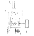
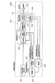
- FIG. 1 is a block diagram showing a basic configuration of a high-frequency heating device 100 according to Embodiment 1 of the high-frequency heating device of the present invention.
- a high-frequency heating device 100 shown in FIG. 1 is a high-frequency heating device that dielectrically heats an object to be heated housed in a heating chamber 101, and includes a control unit 110, a high-frequency power generation unit 120, a high-frequency power unit 130, and radiation. Unit 140 and modulation signal generation unit 150.
- the control unit 110 controls the frequency and phase of a plurality of high frequency powers radiated from the radiation unit 140.
- each high-frequency power radiated from the radiating unit 140 is referred to as a subcarrier wave.
- the control unit 110 outputs a frequency control signal Cfreq of a reference frequency for generating a plurality of subcarrier waves used for heating in the high frequency power unit 130 to the high frequency power generation unit 120.
- control unit 110 outputs, to the modulation signal generation unit 150, information on the offset frequency and phase of the plurality of subcarrier waves used for heating with respect to the reference frequency of each subcarrier wave.
- the high frequency power generation unit 120 is a frequency variable power generation unit that generates high frequency power having a frequency set by the control unit 110.
- a PLL (Phase Locked Loop) oscillator that generates high-frequency power having a frequency corresponding to the frequency control signal Cfreq input from the control unit 110 is used.
- FIG. 2 is a block diagram showing a specific configuration of the high-frequency power generation unit 120.
- the control unit 110 and the high-frequency power unit 130 are shown.
- 2 includes a high-frequency oscillating unit 121, a buffer amplifier 122, and a reference signal oscillator 123.
- the high frequency oscillator 121 includes a high frequency oscillator 124 and a phase comparator 125.
- the high-frequency oscillator 124 is, for example, a VCO (Voltage Controlled Oscillator) that generates a high-frequency signal having a frequency corresponding to the voltage output from the phase comparator 125.
- VCO Voltage Controlled Oscillator
- the phase comparator 125 adjusts the output voltage so that the frequency of the high-frequency power generated from the high-frequency oscillator 124 becomes the frequency set by the frequency control signal Cfreq input from the control unit 110. Specifically, the phase comparator 125 compares the phase of the signal obtained by dividing the high frequency power generated from the high frequency oscillator 124 by N with the signal obtained by dividing the reference signal input from the reference signal oscillator 123 by R. The voltage output to the high-frequency oscillator 124 is adjusted so that both signals have the same phase. As a result, the frequency of the high frequency power generated from the high frequency oscillator 124 is locked to a frequency obtained by multiplying the frequency of the reference signal input from the reference signal oscillator 123 by N / R. By setting the frequency control signal Cfreq indicating the values of N and R from the control unit 110 to the phase comparator 125, the frequency of the high-frequency power generated from the high-frequency oscillator 124 can be controlled.
- the buffer amplifier 122 is, for example, a transistor that amplifies the high frequency power generated by the high frequency oscillation unit 121.
- the reference signal oscillator 123 is an oscillator having a fixed frequency, and is, for example, a TCXO (Temperature Compensated Crystal Oscillator).
- the high frequency power generation unit 120 generates high frequency power having a frequency set by the control unit 110 using the frequency control signal Cfreq.
- the buffer amplifier 122 is shown as a single power amplifier. However, in order to obtain a high output and a large output power, a plurality of power amplifiers are provided and combined in a multistage series connection or in parallel. It may be configured.
- the high frequency power generated by the high frequency power generation unit 120 is input to the high frequency power unit 130.
- the high frequency power unit 130 is generated by quadrature modulating the high frequency power input from the high frequency power generation unit 120 with the in-phase modulation signal Mod (I) and the quadrature modulation signal Mod (Q) input from the modulation signal generation unit 150.
- the subcarrier wave is radiated to the heating chamber 101 through the radiating unit 140.
- the detailed configuration of the high frequency power unit 130 will be described later.
- the radiating unit 140 radiates the subcarrier wave generated by the high frequency power unit 130 to the heating chamber 101, and is, for example, an antenna.
- the radiating unit 140 is drawn separately from the high-frequency power unit 130, but this is only an example, and the radiating unit 140 may be included in the high-frequency power unit 130.
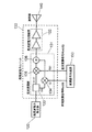
- the high frequency power unit 130 includes an orthogonal modulation unit 131 and a high frequency power amplification unit 132.
- FIG. 3 is a block diagram showing a specific configuration of the high-frequency power unit 130.
- FIG. 3 shows a modulation signal generation unit 150, a high frequency power generation unit 120, and a radiation unit 140.
- the high-frequency power unit 130 includes an orthogonal modulation unit 131 and a high-frequency power amplification unit 132.
- the high frequency power generation unit 120, the quadrature modulation unit 131, the high frequency power amplification unit 132, and the radiation unit 140 are connected in series in this order. Further, the quadrature modulation unit 131 is also connected to the modulation signal generation unit 150.
- the quadrature modulation unit 131 subjects the high-frequency power input from the high-frequency power generation unit 120 to quadrature modulation with the in-phase modulation signal Mod (I) and the quadrature modulation signal Mod (Q) input from the modulation signal generation unit 150, and performs subcarrier modulation. A wave is generated and output to the high frequency power amplifier 132.
- the quadrature modulation unit 131 includes a ⁇ / 2 phase shifter 133, an in-phase modulation mixer 134, a quadrature modulation mixer 135, and an adder 136.
- the in-phase modulation mixer 134 and the quadrature modulation mixer 135 are respectively connected to the modulation signal generation unit 150.
- the ⁇ / 2 phase shifter 133 receives the high-frequency power generated by the high-frequency power generation unit 120, and the in-phase high-frequency power and the orthogonal high-frequency power whose phase is shifted by ⁇ / 2 with respect to the input high-frequency power. Generate power. Then, the in-phase high-frequency power is output to the in-phase modulation mixer 134, and the quadrature high-frequency power is output to the quadrature modulation mixer 135.
- a high frequency power amplifier, a fixed attenuator, and the like are further provided between the high frequency power generation unit 120 and the ⁇ / 2 phase shifter 133. May be provided with a low-pass filter.
- the in-phase modulation mixer 134 multiplies the in-phase high-frequency power input from the ⁇ / 2 phase shifter 133 by the in-phase modulation signal Mod (I) input from the modulation signal generation unit 150, and adds the adder 136. Output to.
- the quadrature modulation mixer 135 modulates the quadrature high frequency power input from the ⁇ / 2 phase shifter 133 by multiplying by the quadrature modulation signal Mod (Q) input from the modulation signal generation unit 150, and The data is output to the adder 136.
- a low-pass filter may be provided between the in-phase modulation mixer 134 and the quadrature modulation mixer 135 and the modulation signal generation unit 150.
- the adder 136 adds the modulated high-frequency power input from the in-phase modulation mixer 134 and the modulated high-frequency power input from the quadrature modulation mixer 135 and outputs the result to the high-frequency power amplification unit 132.
- the high-frequency power amplifier 132 amplifies the subcarrier wave generated by the quadrature modulator 131 with a predetermined amplification factor, for example, is configured by combining transistors in a multistage series connection or in parallel.
- the high-frequency power unit 130 performs quadrature modulation on the high-frequency power input from the high-frequency power generation unit 120 with the in-phase modulation signal Mod (I) and the quadrature modulation signal Mod (Q) input from the modulation signal generation unit 150.
- a subcarrier wave is generated, amplified with a predetermined amplification gain, and radiated to the heating chamber 101 via the radiating unit 140.
- FIG. 4 is a block diagram showing a specific configuration of the modulation signal generation unit 150.
- FIG. 4 shows the control unit 110 and the quadrature modulation unit 131.
- the modulation signal generation unit 150 performs quadrature modulation by the orthogonal modulation unit 131 from the offset frequency and phase information with respect to the reference frequency of each subcarrier wave of the plurality of subcarrier waves input from the control unit 110.
- In-phase modulation signal Mod (I) and quadrature modulation signal Mod (Q) for generating a carrier wave are generated and output to quadrature modulation section 131.
- the modulation signal generation unit 150 includes a baseband calculation unit 151, an I / Q signal generation unit 152, an I-side D / A conversion unit 153, and a Q-side D / A conversion unit 154. Have.
- the baseband calculation unit 151 performs inverse discrete Fourier transform (IDFT: Inverse Discrete Fourier Transform) on the offset frequency and phase information with respect to the reference frequency of each subcarrier wave of the plurality of subcarrier waves input from the control unit 110. As a result, a continuous baseband signal is generated and output to the I / Q signal generation unit 152.
- IDFT Inverse Discrete Fourier Transform
- IFFT Inverse Fast Fourier Transform
- the I / Q signal generation unit 152 generates the real part component of the baseband signal input from the baseband calculation unit 151 as a real part component signal and the imaginary part component as an imaginary part component signal.
- the imaginary part component signal is output to the I-side D / A converter 153 and the Q-side D / A converter 154, respectively.
- the I-side D / A conversion unit 153 performs digital-analog conversion on the real component signal input from the I / Q signal generation unit 152, and converts the real component signal converted to the analog signal into the in-phase modulation signal Mod (I ) To the quadrature modulation unit 131.
- the Q-side D / A conversion unit 154 performs digital-analog conversion on the imaginary part component signal input from the I / Q signal generation unit 152, and converts the imaginary part component signal converted into the analog signal into a quadrature modulation signal. The result is output to the quadrature modulation unit 131 as Mod (Q).
- the I-side D / A conversion unit 153 and the Q-side D / A conversion unit 154 are depicted as one of the components of the modulation signal generation unit 150, but this is merely an example, It may be provided between the modulation signal generation unit 150 and the quadrature modulation unit 131. Furthermore, the I-side D / A conversion unit 153 and the Q-side D / A conversion unit 154 may be included in the quadrature modulation unit 131. Good.
- the modulation signal generation unit 150 receives the orthogonal modulation unit from the offset frequency and phase information with respect to the reference frequency of each subcarrier wave regarding the plurality of subcarrier waves used for heating input from the control unit 110.
- An in-phase modulation signal Mod (I) and a quadrature modulation signal Mod (Q) for generating a subcarrier wave by modulation in 131 are generated.
- the modulation signal generation unit 150 outputs the generated in-phase modulation signal Mod (I) and quadrature modulation signal Mod (Q) to the quadrature modulation unit 131.
- control unit 110 is provided with a subcarrier information storage unit that stores information on predetermined individual subcarrier waves, and the modulation signal generation unit 150 has a plurality of subcarrier waves.
- the subcarrier information may be extracted from the subcarrier information storage unit.
- the subcarrier information storage unit can be easily realized using a semiconductor memory or the like. This facilitates the determination of the subcarriers used for heating, and the frequency and phase of the plurality of subcarrier waves radiated from the radiating unit 140 are more appropriate at high speed so as to execute the heating desired by the user. Can be controlled.
- the high-frequency heating device 100 generates subcarrier waves of a plurality of frequencies and phases for the output of the high-frequency power from the high-frequency power generation unit 120, and the plurality of subcarriers are generated.
- a carrier wave can be simultaneously radiated to the heating chamber 101 via the radiating unit 140.
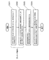
- FIG. 5 is a flowchart showing a control procedure of the high-frequency heating apparatus 100 shown in FIG.
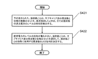
- the high frequency heating apparatus 100 of FIG. 1 performs the following processing in the control unit 110.
- control unit 110 determines the frequency and phase of a plurality of subcarrier waves used for heating (step S101). Specifically, the control unit 110 determines each subcarrier wave of the plurality of subcarrier waves used for heating according to the size and shape of the object to be heated stored in the heating chamber 101 or the user's instruction. Determine frequency and phase values.
- the control unit 110 determines the reference frequency, and the determined high frequency power generation unit 120 is supplied with the determined reference frequency.
- the reference frequency can be determined to any frequency as long as it is within the frequency range of the high frequency power that can be generated by the high frequency power generation unit 120.
- the reference frequency may be selected from a frequency between the lowest frequency and the highest frequency that can be used for heating. It is most common to determine the lowest frequency and the highest center frequency that can be used for heating as the reference frequency.
- control unit 110 outputs the offset frequency and phase information of each subcarrier wave to the modulation signal generation unit 150, and performs the heating process (step S103). Specifically, control unit 110 determines the offset frequency of each subcarrier wave based on the frequency of each subcarrier wave determined in step S101 and the reference frequency determined in step S102.
- the value of the offset frequency of each subcarrier wave determined in this way and the information on the phase of each subcarrier wave determined in step S101 are output to modulated signal generation section 150.
- the value of the offset frequency of each subcarrier wave and the information on the phase of each subcarrier wave are output to the modulation signal generation unit 150, so that the modulation signal generation unit 150 performs the in-phase modulation signal Mod (I ) And a quadrature modulation signal Mod (Q) are generated, and a plurality of subcarrier waves determined in step S101 are generated by the quadrature modulation unit 131 and radiated to the heating chamber 101 via the high-frequency power amplification unit 132 and the radiation unit 140. Then, the heat treatment is executed.
- an intermediate frequency between the lowest frequency and the highest frequency among the frequencies of the plurality of subcarrier waves determined in step S101 may be determined as the reference frequency. Good.
- the maximum value of the absolute value of the offset frequency in each subcarrier wave can be reduced, the signals of the in-phase modulation signal Mod (I) and the quadrature modulation signal Mod (Q) generated by the modulation signal generation unit 150
- the band can be narrowed, and the load on the circuit constituting the modulation signal generation unit 150 can be reduced.
- the load on the signal transmission circuit between the modulation signal generation unit 150 and the orthogonal modulation unit 131 can be reduced. Therefore, the control procedure in the high-frequency heating device 100 of the first embodiment contributes to downsizing, cost reduction, and improvement of circuit reliability.
- the high-frequency heating device 100 of the first embodiment According to the configuration of the high-frequency heating device 100 of the first embodiment, subcarrier waves having a plurality of frequencies and phases are generated with respect to the output of the high-frequency power from the same high-frequency power generation unit 120, and the plurality of those Subcarrier waves can be simultaneously emitted from the same radiating unit 140 into the heating chamber 101. Therefore, the high-frequency heating device 100 according to the first embodiment can simultaneously form a plurality of microwave distributions without increasing the number of oscillators and radiating portions, and can be uniformly heated and variously configured with a small and low-cost configuration. Heating control can be performed.
- the microwave distribution formed inside the heating chamber 101 when the object to be heated is stored in the heating chamber 101 and the high-frequency power is radiated from the radiating unit 140 differs depending on the frequency of the high-frequency power radiated from the radiating unit 140. Distribution characteristics.
- the high-frequency power radiated from the radiating unit 140 to the heating chamber 101 (hereinafter referred to as radiated power) is directly absorbed by the object to be heated (hereinafter referred to as direct absorbed power) and the heating chamber 101.
- Power that is absorbed by the object to be heated after being reflected at least once on the wall surface hereinafter referred to as indirect absorbed power
- the radiation part is not absorbed by the object to be heated.
- backflow power is divided into power that flows back to 140 (hereinafter referred to as backflow power).
- backflow power Directly absorbed power and indirect absorbed power are absorbed by the object to be heated and the object to be heated is heated, but the backflow power is lost power without contributing to heating. Therefore, the smaller the ratio of the backflow power to the radiated power, the greater the power absorbed by the object to be heated and the higher the heating efficiency.
- FIG. 6 shows a case where a heated object is stored in a rectangular parallelepiped heating chamber 101, and single-frequency high-frequency power is supplied to the heating chamber 101 from a radiating unit 140 configured by one patch antenna disposed on the wall surface of the heating chamber 101. It is a figure which shows the characteristic of ratio of the radiant power radiated
- the horizontal axis indicates the frequency [MHz] of the high frequency power radiated from the radiating unit 140.
- the vertical axis represents the ratio of the backflow power to the radiated power radiated from the radiating unit 140 in decibel value [dB].
- dB decibel value
- the power absorption rate to the object to be heated varies depending on the frequency of the high-frequency power radiated from the radiating unit 140.
- the frequency of the high-frequency power radiated from the radiating unit 140 is 2492 MHz
- the backflow power ratio to the radiated power is ⁇ 29 dB
- the power absorption rate to the object to be heated is the largest (point A).
- the ratio of the backflow power to the radiated power is ⁇ 22 dB (point B)
- the frequency of the high-frequency power radiated from the radiating unit 140 is 2450 MHz
- the backflow power ratio is ⁇ 20.5 dB (C point)
- the fact that the power absorption rate to the object to be heated varies depending on the frequency of the high frequency power radiated from the radiating unit 140 means that the microwave distribution varies depending on the frequency of the high frequency power radiated from the radiating unit 140. Means that it is formed. Moreover, it means that the region of the part to be heated strongly differs depending on the frequency of the high frequency power radiated from the radiating unit 140.
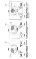
- FIG. 7 shows a case where the frequency at point A shown in FIG. 6 is fA, the frequency at point B is fB, and the frequency at point C is fC, and high-frequency power of each frequency is radiated from the radiating unit 140 to the heating chamber 101.
- the state of the distribution of microwaves is schematically shown.
- FIG. 7A shows a microwave distribution 171 for an object to be heated housed in the heating chamber 101 when the frequency of the high-frequency power radiated from the radiating unit 140 is fA.
- FIG. 7B shows a microwave distribution 172 for an object to be heated housed in the heating chamber 101 when the frequency of the high-frequency power radiated from the radiating unit 140 is fB.
- FIG. 7C shows a microwave distribution 173 for an object to be heated stored in the heating chamber 101 when the frequency of the high-frequency power radiated from the radiating unit 140 is fC.
- the control unit 110 determines these frequencies fA, fB, and fC as subcarrier wave frequencies (step S101). Subsequently, after determining the reference frequency in step S102, a plurality of subcarrier waves are generated in step S103, and heating is performed.
- FIG. 8 shows the state of the microwave distribution with respect to the object to be heated stored in the heating chamber 101 when the three subcarrier waves having the frequencies fA, fB, and fC are simultaneously emitted from the radiating unit 140 in step S103. It is the figure shown typically. As shown in FIG. 8, the microwave distribution when the three subcarrier waves having the frequencies of fA, fB, and fC are simultaneously emitted from the radiating unit 140 is the microwave distribution when the high-frequency power of each frequency is individually radiated. It can be seen that the wave distributions are all formed simultaneously.
- the high-frequency heating device 100 is a high-frequency heating device that heats an object to be heated housed in the heating chamber 101, and at least one high-frequency power that generates high-frequency power having a set frequency.
- the power generation unit 120, the quadrature modulation unit 131 that modulates the high-frequency power generated by the high-frequency power generation unit 120 with the input modulation signal, and the high-frequency power modulated by the quadrature modulation unit 131 is of a size suitable for heating.
- At least one high-frequency power unit 130 each including a high-frequency power amplification unit 132 that amplifies the power, at least one radiation unit 140 that radiates high-frequency power output from the high-frequency power unit 130 to an object to be heated, and an input A modulation signal generation unit 150 that generates a modulation signal to be supplied to the quadrature modulation unit 131 from the information on the plurality of frequencies and phases, and radiation A control unit that sets a reference frequency of the high-frequency power radiated from 140 to the high-frequency power generation unit 120 and outputs information on individual frequencies and phases of the plurality of high-frequency powers radiated from the radiation unit 140 to the modulation signal generation unit 150 110.
- the control unit 110 supplies the modulation signal generation unit 150 with a plurality of pieces of subcarrier information that individually include offset frequency and phase information of the plurality of high-frequency powers radiated from the radiation unit 140 with respect to the reference frequency,
- the generation unit 150 generates an in-phase modulation signal and a quadrature modulation signal based on the plurality of subcarrier information supplied from the control unit 110, and outputs the in-phase modulation signal and the quadrature modulation signal to the quadrature modulation unit 131.
- the high-frequency power input from the generator 120 is quadrature-modulated with the in-phase modulation signal and the quadrature modulation signal input from the modulation signal generator 150, and a plurality of subcarrier waves having an offset frequency and phase with respect to the reference frequency are output.
- Modulation signal generation section 150 generates an in-phase modulation signal and a quadrature modulation signal by inverse fast Fourier transform (IFFT) calculation processing on the plurality of subcarrier information supplied from control section 110 and supplies the same to quadrature modulation section 131. To do.
- IFFT inverse fast Fourier transform
- the control unit 110 further includes a subcarrier information storage unit that stores a plurality of predetermined subcarrier information, and takes out a plurality of subcarrier information appropriate when performing heating from the subcarrier information storage unit,
- the reference frequency is set in the power generation unit 120 and the subcarrier information is output to the modulation signal generation unit 150.
- the control unit 110 determines the reference frequency so that the maximum absolute value of the offset frequency with respect to the reference frequency in the plurality of subcarrier waves is minimized, and sets the frequency in the high-frequency power generation unit 120.
- a plurality of high-frequency powers having a plurality of frequencies and phases are generated for one high-frequency power output from the high-frequency power generation unit 120, and the plurality of high-frequency powers are supplied to the same radiation unit. 140 can be simultaneously sent to an object to be heated. As a result, a plurality of microwave distributions can be simultaneously formed without increasing the number of oscillators and radiating portions, and uniform heating and various heating controls can be realized with a small size and low cost.
- the high-frequency heating device 100 includes one high-frequency power generation unit 120, a high-frequency power unit 130, and a radiation unit 140. Since carrier waves are radiated simultaneously, a plurality of microwave distributions can be simultaneously formed in the heating chamber 101, and heating control in a wide heating region such as uniform heating can be easily performed with a small size and low cost. Can do.
- the high-frequency heating device 100 of the first embodiment described above has a set of high-frequency power units 130, a radiation unit 140, and a modulation signal generation unit 150, whereas the high-frequency heating device of the second embodiment. Is different in that it has at least two sets of high-frequency power units, a radiation unit, and a modulation signal generation unit.
- the high-frequency heating device of the second embodiment can control the heating region more efficiently and variably by radiating high-frequency power having a plurality of frequencies and phases from a plurality of radiating units.
- the high-frequency heating device according to the second embodiment will be described focusing on the differences from the first embodiment.
- components having the same functions as those of the first embodiment are denoted by the same reference numerals, and the description thereof is omitted. Also, the description of the content having the same action as in the first embodiment is omitted.
- FIG. 9 is a block diagram showing the configuration of the high-frequency heating device according to the second embodiment of the present invention.
- the high-frequency heating device 200 shown in FIG. 9 is different from the high-frequency heating device 100 of the first embodiment shown in FIG. 1 in place of the high-frequency power unit 130, and the first high-frequency power unit 230a and the second high-frequency power unit. 230b, a first radiation unit 240a and a second radiation unit 240b instead of the radiation unit 140, and a first modulation signal generation unit 250a and a second modulation signal instead of the modulation signal generation unit 150.
- the distribution unit 260 is further provided.
- the high frequency power generation unit 120 generates high frequency power having a frequency set by the frequency control signal Cfreq input from the control unit 210.
- the generated high frequency power is distributed by the distribution unit 260 and input to the first high frequency power unit 230a and the second high frequency power unit 230b. That is, the high frequency power generation unit 120 supplies high frequency power to the first high frequency power unit 230a and the second high frequency power unit 230b.
- the first high-frequency power unit 230a converts the high-frequency power input from the distribution unit 260 into the in-phase modulation signal Mod (I) 1 and the quadrature modulation signal Mod (Q) 1 input from the first modulation signal generation unit 250a.
- a subcarrier wave generated by orthogonal modulation is radiated to the heating chamber 101 via the first radiating section 240a.
- the second high frequency power unit 230b uses the high frequency power input from the distribution unit 260 as the in-phase modulation signal Mod (I) 2 and the quadrature modulation signal Mod (Q) input from the second modulation signal generation unit 250b. 2 radiates the subcarrier wave generated by the quadrature modulation by 2 to the heating chamber 101 via the second radiating unit 240b.
- the first high-frequency power unit 230a includes an orthogonal modulation unit 231a and a high-frequency power amplification unit 232a.
- the second high-frequency power unit 230b includes an orthogonal modulation unit 231b and a high-frequency power amplification unit 232b.
- the quadrature modulation unit 231a performs quadrature modulation on the high frequency power input from the distribution unit 260 with the in-phase modulation signal Mod (I) 1 and the quadrature modulation signal Mod (Q) 1 input from the first modulation signal generation unit 250a. Then, a subcarrier wave is generated and output to the high frequency power amplifier 232a. Further, the quadrature modulation unit 231b orthogonalizes the high frequency power input from the distribution unit 260 with the in-phase modulation signal Mod (I) 2 and the quadrature modulation signal Mod (Q) 2 input from the second modulation signal generation unit 250b. Modulates to generate a subcarrier wave and outputs the subcarrier wave to the high frequency power amplifier 232b.
- the high-frequency power amplification unit 232a amplifies the subcarrier wave generated by the orthogonal modulation unit 231a with a predetermined amplification factor, and outputs the amplified signal to the first radiation unit 240a.
- the high frequency power amplifier 232b amplifies the subcarrier wave generated by the quadrature modulator 231b with a predetermined amplification factor and outputs the amplified signal to the second radiating unit 240b.
- the specific configurations of the orthogonal modulation units 231a and 231b and the high-frequency power amplification units 232a and 232b are the specific configurations of the orthogonal modulation unit 131 and the high-frequency power amplification unit 132 shown in FIG. 3 described in the first embodiment. Since the configuration is the same, the description thereof is omitted.
- the first radiating unit 240a and the second radiating unit 240b radiate the subcarrier waves generated by the first high-frequency power unit 230a and the second high-frequency power unit 230b, respectively, to the heating chamber 101.
- It is an antenna.
- the first radiating unit 240a and the second radiating unit 240b are drawn separately from the first high-frequency power unit 230a and the second high-frequency power unit 230b, but this is only an example.
- the first high-frequency power unit 230a and the second high-frequency power unit 230b may include the first radiating unit 240a and the second radiating unit 240b.
- the controller 210 controls the frequency and phase of a plurality of subcarriers radiated from the first radiating unit 240a and the second radiating unit 240b, respectively. Specifically, the control unit 210 generates a frequency control signal Cfreq having a reference frequency for generating a plurality of subcarrier waves used for heating in the first high-frequency power unit 230a and the second high-frequency power unit 230b. Output to the generator 120.
- control unit 210 performs first modulation on the offset frequency and phase information of the plurality of subcarrier waves generated by the first high frequency power unit 230a used for heating with respect to the reference frequency of each subcarrier wave.
- the signal is output to the signal generator 250a.
- control unit 210 performs second modulation on the offset frequency and phase information of the plurality of subcarrier waves generated by the second high-frequency power unit 230b used for heating with respect to the reference frequency of each subcarrier wave. It outputs to the signal generation part 250b.
- the first modulation signal generation unit 250a is input from the control unit 210 and is based on offset frequency and phase information with respect to the reference frequency of each subcarrier wave of the plurality of subcarrier waves generated by the first high frequency power unit 230a.
- the in-phase modulation signal Mod (I) 1 and the quadrature modulation signal Mod (Q) 1 are generated and output to the quadrature modulation unit 231a.
- the second modulation signal generation unit 250b receives the offset frequency and phase of the plurality of subcarrier waves generated by the second high-frequency power unit 230b input from the control unit 210 with respect to the reference frequency of each subcarrier wave. From the information, an in-phase modulation signal Mod (I) 2 and a quadrature modulation signal Mod (Q) 2 are generated and output to the quadrature modulation unit 231b.
- the specific configurations of the first modulation signal generation unit 250a and the second modulation signal generation unit 250b are the same as the specific configuration of the modulation signal generation unit 150 shown in FIG. 4 described in the first embodiment. Since it is the same, description is abbreviate
- the distribution unit 260 distributes the high-frequency power input from the high-frequency power generation unit 120 in two, and inputs the distributed high-frequency power to the first high-frequency power unit 230a and the second high-frequency power unit 230b.
- a resistance distributor may be used, and either a directional coupler or a hybrid coupler may be used.
- the control unit 210 supplies the first high-frequency power unit to the two modulation signal generation units, that is, the first modulation signal generation unit 250 a and the second modulation signal generation unit 250 b.
- Information on offset frequency and phase with respect to reference frequency of each subcarrier wave of the plurality of subcarrier waves generated in 230a, and reference of individual subcarrier wave of the plurality of subcarrier waves generated in second high frequency power unit 230b Outputs offset frequency and phase information for frequency.
- control unit 210 controls the individual frequencies and phases of the plurality of subcarrier waves generated by the first high frequency power unit 230a and the individual subcarrier waves of the plurality of subcarrier waves generated by the second high frequency power unit 230b.
- the frequency and phase of the carrier wave are set independently of each other.
- the basic control procedure of the high-frequency heating device 200 of the second embodiment is the same as the control procedure of the high-frequency heating device 100 described in the first embodiment.
- one set of the high-frequency power unit 130 and the radiation unit 140 correspond to one high-frequency power generation unit 120.
- two sets of the first high-frequency power unit 230a, the first radiating unit 240a, and the second The high frequency power unit 230b and the second radiation unit 240b correspond to each other. With this configuration, it is possible to radiate a plurality of subcarriers set independently from each other from a plurality of radiation units.
- the control of the microwave distribution by the difference in the installation positions of the radiating portions 240a and 240b, and further in the heating chamber 101
- the microwave distribution can be controlled by combining the spatial power of the microwaves, and more complicated heating region can be controlled.
- the high-frequency heating apparatus 200 includes two sets of high-frequency power units, a radiating unit, and a modulation signal generating unit (a first high-frequency power unit 230a, a first radiating unit 240a, and a first modulation signal generating unit 250a.
- a modulation signal generating unit a first high-frequency power unit 230a, a first radiating unit 240a, and a first modulation signal generating unit 250a.
- the second high-frequency power unit 230b, the second radiating unit 240b, and the second modulation signal generating unit 250b the number of sets of the high-frequency power unit, the radiating unit, and the modulation signal generating unit is as described above.
- the present invention is not limited to the configuration, and in the present invention, it is only necessary to have a plurality of sets of high-frequency power units, radiation units, and modulation signal generation units.
- Heating when the object to be heated is stored in the heating chamber 101 and high-frequency power of a certain frequency (for example, frequency fA) is radiated from a plurality of radiating parts (first radiating part 240a and second radiating part 240b).
- the microwave distribution formed inside the chamber 101 has different distribution characteristics depending on the radiation part (the first radiation part 240a and the second radiation part 240b) from which the high-frequency power is radiated.
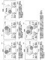
- FIG. 10 is a plan view of a first radiating portion 240a and a second radiating portion 240b configured by two patch antennas arranged on the wall surface of the heating chamber 101. It is a figure which shows typically the mode of the microwave distribution with respect to a to-be-heated object when the high frequency electric power of one frequency (for example, frequency fA) is radiated
- one frequency for example, frequency fA
- FIG. 10 (a) shows a microwave distribution 271a for an object to be heated housed in the heating chamber 101 when high-frequency power of frequency fA is radiated only from the first radiating section 240a.
- FIG. 10B shows a microwave distribution 271b for an object to be heated housed in the heating chamber 101 when high-frequency power of frequency fA is radiated only from the second radiating portion 240b.
- FIG. 10 (c) shows a microwave distribution 271c for an object to be heated housed in the heating chamber 101 when high-frequency power of frequency fA is simultaneously radiated from the first radiating section 240a and the second radiating section 240b. ing.
- the second radiating portion when the radiating portions (first radiating portion 240a and second radiating portion 240b) that radiate high-frequency power of frequency fA are only the first radiating portion 240a, the second radiating portion.
- first radiating portion 240a and second radiating portion 240b when only 240b is used, different microwave distributions are formed when the first radiating portion 240a and the second radiating portion 240b are simultaneously radiated.
- FIG. 10 it can be understood that, by different radiation portions that radiate high-frequency power, regions of different portions are strongly heated with respect to the object to be heated.
- the high frequency power having the frequency fA shown in FIG. 10C is simultaneously radiated from the first radiating unit 240a and the second radiating unit 240b, the high frequency power shown in FIG.
- the microwave distribution when high-frequency power is radiated only from one radiating portion 240a and the microwave distribution when high-frequency power is radiated only from the second radiating portion 240b shown in FIG. Wave distribution is shown. This is because when high-frequency power having the same frequency is simultaneously radiated from the plurality of radiating parts (the first radiating part 240a and the second radiating part 240b) to the heating chamber 101, the respective radiating parts (first This is because the high frequency power radiated from the radiating unit 240 a and the second radiating unit 240 b) is combined with the spatial power in the heating chamber 101.
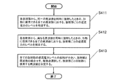
- control procedure of the high-frequency heating device 200 of the second embodiment will be described using the flowchart of FIG. 5 used in the description of the control procedure of the high-frequency heating device 100 of the first embodiment.
- the control unit 210 determines the frequency and phase of each subcarrier wave for each radiating unit (first radiating unit 240a and second radiating unit 240b) that radiates subcarrier waves (step S101). Subsequently, after the reference frequency is determined in step S102, the modulation signal generation unit (first modulation signal generation) corresponding to each of the radiation units (first radiation unit 240a and second radiation unit 240b) is determined in step S103.
- Unit 250a and second modulation signal generation unit 250b) output frequency and phase information of individual subcarrier waves, and radiate from the respective radiation units (first radiation unit 240a and second radiation unit 240b). A plurality of subcarrier waves are generated. The plurality of generated subcarrier waves are radiated from the first radiating unit 240a and the second radiating unit 240b, and the heating process is executed.
- FIG. 11 shows the respective radiation parts (the first radiation part 240a and the second radiation part) when high-frequency power is simultaneously radiated from the plurality of radiation parts (the first radiation part 240a and the second radiation part 240b). It is the figure which showed typically a mode that the microwave distribution with respect to a to-be-heated object changed by changing the phase difference of the high frequency electric power radiated
- FIG. 11A shows the heating chamber 101 when the first radiating unit 240a simultaneously radiates high-frequency power of frequency fA and phase ⁇ A and the second radiating unit 240b simultaneously radiates high-frequency power of frequency fA and phase ⁇ B.
- the microwave distribution 272a with respect to the to-be-heated material accommodated is shown.
- the spatial power is synthesized in the heating chamber 101 to form the microwave distribution 272a. Yes.
- FIG. 11B shows the heating chamber 101 when the first radiating unit 240a simultaneously radiates high-frequency power of frequency fA and phase ⁇ A and the second radiating unit 240b radiates high-frequency power of frequency fA and phase ⁇ C at the same time.
- the microwave distribution 272b with respect to the to-be-heated material accommodated is shown.
- the phase of the high frequency power radiated from the second radiating section 240b is different from that in the case of FIG.
- the phase difference between the high-frequency powers radiated from the two radiating portions is ⁇ B ⁇ A, whereas in FIG.
- the phase difference between the high-frequency powers radiated from the two radiating portions is ⁇ C ⁇ A.
- the phase difference between the high frequency powers is different.
- Different microwave distribution By changing this phase difference, various microwave distributions can be formed in the heating chamber 101.
- FIG. 11 (c) and FIG. 11 (d) are different from the cases of FIG. 11 (a) and FIG. 11 (b) in the respective radiation portions (the first radiation portion 240a and the second radiation).
- the state of the microwave distribution when the frequency of the high frequency power radiated from the unit 240b) is changed is shown.
- FIG. 11C shows the heating chamber 101 when high-frequency power of frequency fB and phase ⁇ D is simultaneously radiated from the first radiating section 240a and high-frequency power of frequency fB and phase ⁇ E is simultaneously radiated from the second radiating section 240b.
- the microwave distribution 272c with respect to the to-be-heated material accommodated is shown.
- 11D shows a heating chamber in which high-frequency power of frequency fB and phase ⁇ D is simultaneously radiated from the first radiating section 240a, and high-frequency power of frequency fB and phase ⁇ F is radiated from the second radiating section 240b simultaneously.
- a microwave distribution 272d for an object to be heated housed in 101 is shown.
- the respective radiating portions (the first radiating portion 240a and the second radiating portion). Since the frequency of the high-frequency power radiated from the part 240b) is the same, the spatial power is synthesized in the heating chamber 101 to form the microwave distributions 272c and 272d, respectively.
- the respective microwave distributions (microwave distributions 272c and 272d) differ from each other in the respective radiating portions (the first radiating portion 240a and the second radiating portion). This is because the phase difference of the high-frequency power radiated from the radiating section 240b) is different. In the case of FIG. 11C, the phase difference is ⁇ E ⁇ D, whereas in the case of FIG. 11D, the phase difference is ⁇ F ⁇ D, and the phase difference is different.
- FIG. 11 shows two high frequency powers of frequency fA, phase ⁇ A, frequency fB, and phase ⁇ D from the first radiation unit 240a, and frequency fA, phase ⁇ B, and frequency fB from the second radiation unit 240b.
- Microwave distributions 272a and 272d formed in the heating chamber 101 when two high-frequency powers of phase ⁇ F are simultaneously emitted.
- FIG. 11 (e) it can be understood that the microwave distribution 272a in the case of FIG. 11 (a) and the microwave distribution 272d in the case of FIG. 11 (d) are formed simultaneously. This is because high frequency powers having different frequencies do not interfere with each other.
- the high-frequency heating device 200 has two sets of the first high-frequency power unit 230a, the first radiating unit 240a, and the second high-frequency power for one high-frequency power generation unit 120. Since the unit 230b and the second radiating unit 240b correspond to each other, high-frequency power of a plurality of arbitrary frequencies can be radiated simultaneously from the first radiating unit 240a and the second radiating unit 240b. Furthermore, a plurality of combinations of high-frequency powers having the same frequency and different phases can be radiated simultaneously from the first radiating unit 240a and the second radiating unit 240b.
- the high-frequency heating device of the third embodiment further includes a demodulator in the configuration of the high-frequency heating device 100 of the above-described first embodiment, and the high-frequency power unit 130 in the high-frequency heating device 100 of the first embodiment further includes a distribution unit.
- the point which has an electric power detection part differs from the structure of the high frequency heating apparatus 100 of Embodiment 1.
- the high-frequency heating device individually receives a plurality of subcarrier waves radiated from the radiating unit 140 to the heating chamber 101 and a plurality of subcarrier waves flowing back from the heating chamber 101 to the radiating unit 140. Can be detected for each subcarrier wave. Therefore, the high frequency heating apparatus according to the third embodiment can grasp the efficiency for each individual subcarrier wave, and can control the heating region more efficiently and variously.
- the high-frequency heating device according to the third embodiment will be described focusing on the differences from the first embodiment.
- components having the same functions as those of the first embodiment are denoted by the same reference numerals, and the description thereof is omitted. Also, the description of the content having the same action as in the first embodiment is omitted.
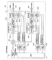
- FIG. 12 is a block diagram showing the configuration of the high-frequency heating device according to the third embodiment of the present invention.
- a high-frequency heating device 300 shown in FIG. 12 includes a high-frequency power unit 330 instead of the high-frequency power unit 130 as compared with the high-frequency heating device 100 of the first embodiment shown in FIG.
- a demodulator 380 is further provided.
- the high frequency power generation unit 120 generates high frequency power having a frequency set by the frequency control signal Cfreq input from the control unit 210 and is input to the high frequency power unit 330.
- the high frequency power unit 330 is generated by quadrature modulating the high frequency power input from the high frequency power generation unit 120 with the in-phase modulation signal Mod (I) and the quadrature modulation signal Mod (Q) input from the modulation signal generation unit 150.
- the subcarrier wave is radiated to the heating chamber 101 through the radiating unit 140. Further, the high-frequency power unit 330 detects the subcarrier wave output from the high-frequency power unit 330 to the radiating unit 140 and the subcarrier wave flowing backward from the radiating unit 140 to the high-frequency power unit 330 to detect the in-phase detection signal Det (I ) And quadrature detection signal Det (Q) to demodulation section 380.
- the high frequency power unit 330 further includes a distribution unit 339 and a power detection unit 390 as compared with the high frequency power unit 130 in the first embodiment shown in FIG.
- FIG. 13 is a block diagram showing a specific configuration of the high-frequency power unit 330.
- FIG. 13 shows the high-frequency power generation unit 120, the radiation unit 140, the modulation signal generation unit 150, and the demodulation unit 380.
- the high frequency power unit 330 further includes a distribution unit 339 and a power detection unit 390 as compared with the high frequency power unit 130 according to Embodiment 1 shown in FIG.
- the distribution unit 339 distributes the high-frequency power input from the high-frequency power generation unit 120 and inputs the distributed high-frequency power to the quadrature modulation unit 131 and the power detection unit 390.
- a resistance distributor may be used, and either a directional coupler or a hybrid coupler may be used.
- the quadrature modulation unit 131 quadrature-modulates the high-frequency power input from the distribution unit 339 with the in-phase modulation signal Mod (I) and the quadrature modulation signal Mod (Q) input from the modulation signal generation unit 150 to generate a subcarrier wave. It is generated and output to the high frequency power amplifier 132.
- the high frequency power amplifying unit 132 amplifies the subcarrier wave generated by the quadrature modulation unit 131 with a predetermined amplification factor, and outputs the amplified subcarrier wave to the radiating unit 140 via the power detection unit 390.
- the specific configurations and operations of the quadrature modulation unit 131 and the high frequency power amplification unit 132 are the specific configurations and operations of the quadrature modulation unit 131 and the high frequency power amplification unit 132 shown in FIG. 3 described in the first embodiment. Since it is the same, description is abbreviate
- the power detection unit 390 includes a directional coupling unit 391 and a quadrature detection unit 392.
- the directional coupling unit 391 demultiplexes a part of the high-frequency power output from the high-frequency power amplification unit 132 to the radiation unit 140 or the part of the high-frequency power flowing back from the radiation unit 140 to the high-frequency power amplification unit 132 to be orthogonal. While inputting into the detection part 392, the high frequency electric power amplified by the high frequency electric power amplification part 132 is output to the radiation
- the directional coupler 391 for example, a commonly used directional coupler may be used, or either a circulator or a hybrid coupler may be used.
- the quadrature detection unit 392 demodulates each subcarrier wave by performing quadrature detection on the demultiplexed power input from the directional coupling unit 391 using the high frequency power input from the high frequency power generation unit 120.
- the in-phase detection signal Det (I) and the quadrature detection signal Det (Q) are detected.
- the quadrature detection unit 392 includes a ⁇ / 2 phase shifter 393, an in-phase detection mixer 394, and a quadrature detection mixer 395.
- the in-phase detection mixer 394 and the quadrature detection mixer 395 are respectively connected to the demodulation unit 380. It is connected.
- the ⁇ / 2 phase shifter 393 receives the high-frequency power distributed by the distribution unit 339, and generates in-phase in-phase high-frequency power and orthogonal high-frequency power phase-shifted by ⁇ / 2 with respect to the input high-frequency power. Is done.
- the in-phase high-frequency power is output to the in-phase detection mixer 394, and the quadrature high-frequency power is output to the quadrature detection mixer 395.
- a high-frequency power amplifier, a fixed attenuator, and a low frequency band are provided between the distribution unit 339 and the quadrature detection unit 392.
- a pass filter may be provided.
- the demultiplexed power demultiplexed by the directional coupling unit 391 is input to the quadrature detection unit 392.
- the demultiplexed power input to the quadrature detection unit 392 is divided into two and input to the in-phase detection mixer 394 and the quadrature detection mixer 395, respectively.
- a high-frequency power amplifier, a fixed attenuator, or a low frequency band is provided between the directional coupling unit 391 and the quadrature detection unit 392.
- a pass filter may be provided.
- the in-phase detection mixer 394 performs detection by multiplying the demultiplexed power by the in-phase high frequency power input from the ⁇ / 2 phase shifter 393, that is, synchronous detection of the demultiplexed power with the in-phase high frequency power.
- the in-phase detection signal Det (I) is output to the demodulation unit 380 as a result of this synchronous detection, that is, as a result of multiplication of two input signals.
- the quadrature detection mixer 395 performs detection by multiplying the demultiplexed power by the quadrature high-frequency power input from the ⁇ / 2 phase shifter 393, that is, synchronously detects the demultiplexed power with the quadrature high-frequency power.
- the quadrature detection signal Det (Q) is output to the demodulation unit 380 as a result of this synchronous detection, that is, as a result of multiplication of two input signals.
- a low-pass filter is provided between each of the in-phase detection mixer 394 and the quadrature detection mixer 395 and the demodulation unit 380 in order to optimize the detection characteristics of the quadrature detection unit 392. Also good.
- the high frequency power unit 330 performs quadrature modulation of the high frequency power input from the high frequency power generation unit 120 with the in-phase modulation signal Mod (I) and the quadrature modulation signal Mod (Q) input from the modulation signal generation unit 150. Then, a subcarrier wave is generated and radiated to the heating chamber 101 via the radiating unit 140. Further, by detecting the radiated power radiated to the heating chamber 101 or the backflow power flowing backward from the heating chamber 101, an in-phase detection signal Det (I) for demodulating individual subcarrier waves of the radiated power or the reverse flow power, and The quadrature detection signal Det (Q) is output to the demodulator 380.
- the radiation unit 140 is, for example, an antenna that radiates the subcarrier wave generated by the high-frequency power unit 330 to the heating chamber 101.
- the radiating unit 140 is drawn separately from the high frequency power unit 330, but this is merely an example, and the high frequency power unit 330 may include the radiating unit 140.
- the control unit 310 controls the frequency and phase of a plurality of subcarrier waves radiated from the radiating unit 140 to the heating chamber 101. Specifically, control unit 310 outputs a frequency control signal Cfreq of a reference frequency for generating a plurality of subcarrier waves used for heating in high frequency power unit 330 to high frequency power generation unit 120.
- control unit 310 outputs, to the modulation signal generation unit 150, information on offset frequencies and phases of a plurality of subcarrier waves generated by the high-frequency power unit 330 used for heating with respect to the reference frequency of each subcarrier wave. To do.
- control unit 310 determines the frequency and phase of each subcarrier wave that is optimal for heating based on the frequency and vector information of each subcarrier wave input from the demodulation unit 380.
- the modulation signal generation unit 150 receives the in-phase modulation signal Mod () from the offset frequency and phase information with respect to the reference frequency of each subcarrier wave of the plurality of subcarrier waves generated by the high frequency power unit 330 input from the control unit 310. I) and the quadrature modulation signal Mod (Q) are generated and output to the quadrature modulation unit 131.
- the specific configuration of the modulation signal generation unit 150 is the same as the specific configuration of the modulation signal generation unit 150 shown in FIG. 4 described in the first embodiment. Is omitted.
- Demodulation section 380 demodulates in-phase detection signal Det (I) and quadrature detection signal Det (Q), which are generated by quadrature detection of the demultiplexed power of radiated power or backflow power input from quadrature detection section 392. . Further, the demodulation unit 380 detects information on the frequency and vector of each subcarrier wave in the demultiplexed power of the radiated power or the backflow power, and detects each subcarrier wave in the demultiplexed power of the radiated power or the backflow power. The frequency and vector information are input to the control unit 310.
- FIG. 14 is a block diagram showing a specific configuration of the demodulator 380. In the figure, a control unit 310 and a quadrature detection unit 392 are shown.
- the demodulation unit 380 includes an I-side A / D conversion unit 381, a Q-side A / D conversion unit 382, and a conversion calculation unit 383.
- the I-side A / D conversion unit 381 performs analog-to-digital conversion on the in-phase detection signal Det (I) input from the quadrature detection unit 392 and outputs the in-phase detection signal converted into a digital signal to the conversion operation unit 383. To do.
- the Q-side A / D conversion unit 382 performs analog-to-digital conversion on the quadrature detection signal Det (Q) input from the quadrature detection unit 392, and converts the quadrature detection signal converted into a digital signal into a conversion calculation unit. It outputs to 383.
- the I-side A / D conversion unit 381 and the Q-side A / D conversion unit 382 are depicted as one of the components of the demodulation unit 380, but this is merely an example, and quadrature detection is performed.
- the I-side A / D conversion unit 381 and the Q-side A / D conversion unit 382 may be included in the quadrature detection unit 392.
- the conversion operation unit 383 performs discrete Fourier transform (DFT: Discrete Fourier Transform) on the in-phase detection signal and the direct detection signal input from the I-side A / D conversion unit 381 and the Q-side A / D conversion unit 382 to obtain a frequency.
- DFT discrete Fourier transform
- the frequency and vector information of each subcarrier wave is detected, and the detected frequency and vector information of each subcarrier wave is output to the control unit 310.
- a fast Fourier transform (FFT) can also be used for the calculation of DFT.
- the demodulation unit 380 generates the in-phase detection signal Det (I) and the quadrature detection signal Det (Q) generated by performing quadrature detection on the demultiplexed power of the radiated power or the backflow power input from the quadrature detection unit 392. Is detected, and the frequency and vector information of each subcarrier wave of radiated power or backflow power demultiplexed power is detected, and the frequency of each subcarrier wave of radiated power or backflow power demultiplexed power detected is detected. And vector information to the controller 310.
- FIG. 15 is a flowchart showing a control procedure of the high-frequency heating device 300 according to the third embodiment shown in FIG.
- the high frequency heating apparatus 300 of FIG. 12 performs the following processing in the control unit 310.
- the control unit 310 detects the level of backflow power at all frequencies that can be used for heating (step S301). Specifically, the control unit 310 sets the frequency that can be used for heating as the frequency of the subcarrier wave, inputs information on the frequency of the subcarrier wave to the modulation signal generation unit 150, and the high frequency power unit 330 generates the subcarrier wave frequency. It is generated and output to the radiation unit 140. At this time, the control unit 310 detects the backflow power flowing back from the radiation unit 140 to the high frequency power unit 330 by the power detection unit 390, and the frequency and vector of each subcarrier wave of the backflow power input from the demodulation unit 380. Using the information, the level of backflow power at the frequency of each subcarrier wave is detected.
- the vector information of a signal having a magnitude and a phase is generally expressed by orthogonal coordinates.
- a method for detecting the level and phase of each subcarrier wave from the vector information of each subcarrier wave when the vector information of the subcarrier wave is expressed by orthogonal coordinates will be described with reference to the drawings.
- FIG. 16 is a diagram representing the vector information of one subcarrier wave of each subcarrier wave of the backflow power input from the demodulator 380 in orthogonal coordinates.
- the vertical axis is the Q axis and the horizontal axis is the I axis.
- the level and phase of the subcarrier wave are indicated by one vector 385.
- the length of the arrow of the vector 385 represents the level, and the angle ⁇ of the arrow represents the phase.
- the vector 385 indicating the level and phase of the subcarrier wave is indicated by the coordinate value D (I) on the I axis and the coordinate value D (Q) on the Q axis as vector information.
- the coordinate value D (I) on the I axis and the coordinate value D (Q) on the Q axis may be referred to as a coordinate value D (I) and a coordinate value D (Q).
- the coordinate value D (I) and the coordinate value D (Q) are the intersection point of the I axis and the Q axis as the origin O, the origin O is 0, and the coordinate value D (I) is positive on the right side of the origin O.
- the left side of the origin O is negative, and is indicated by a signed numerical value.
- the coordinate value D (Q) is indicated by a signed numerical value, with the upper side from the origin O being positive and the lower side from the origin O being negative.
- the level and phase of the subcarrier wave can be obtained by calculation. Specifically, the level is calculated from the mean square of the coordinate value D (I) and the coordinate value D (Q), and the phase is a value obtained by dividing the coordinate value D (Q) by the coordinate value D (I). It is calculated from the arc tangent (tan ⁇ 1 ).
- the level and phase of all subcarrier waves are detected individually from the vector information of the individual subcarrier waves of the backflow power input from the demodulator 380.
- the method of detecting the level of backflow power at all frequencies that can be used for heating is (1) Using all the frequencies that can be used for heating as subcarrier wave frequencies, the high-frequency power unit 330 generates subcarrier waves of all frequencies that can be used for heating, and is used for heating by detecting backflow power once. A method for detecting the backflow power level of subcarrier waves of all possible frequencies; (2) Divide the frequencies that can be used for heating into at least two or more groups. First, the frequency included in the first group is set as the frequency of the subcarrier wave, and the frequency included in the first group in the high frequency power unit 330.
- a subcarrier wave is generated, a backflow power is detected, and a backflow power level of a subcarrier wave having a frequency included in the first group is detected.
- the high-frequency power unit 330 uses the frequency included in the second group as the frequency of the subcarrier wave, the high-frequency power unit 330 generates a subcarrier wave of the frequency included in the second group, detects the backflow power, The level of the backflow power of the subcarrier wave of the frequency included in the group is detected.
- There is a method of detecting the backflow power levels of the subcarrier waves of all frequencies that can be used for heating by repeatedly executing this in all the divided groups.
- the level of the backflow power of all the frequencies that can be used for heating can be detected by detecting the backflow power once, so step S301 can be executed in a very short time. it can.
- the reference frequency set in the high-frequency power generation unit 120 is determined to be a frequency just between the lowest frequency and the highest frequency that can be used for heating. For example, when the range of frequencies that can be used for heating is 2400 MHz to 2500 MHz, the reference frequency is preferably determined to be 2450 MHz.
- the frequencies that can be used for heating are divided into a plurality of groups, and the reverse power of the frequencies included in the group is detected in order for each group.
- a power detection operation is required, and it takes a longer time to execute step S301 as compared with the method (1) described above.
- the reference frequency set in the high-frequency power generation unit 120 is determined to be an intermediate frequency between the lowest frequency and the highest frequency of the frequencies included in each group for each group. That is, for each group, the reference frequency set in the high frequency power generation unit 120 is set to a different frequency.
- the high-frequency power unit 330 allows the individual subcarrier waves input to the modulation signal generation unit 150 to generate subcarrier waves of frequencies included in each group.
- the absolute value of the offset frequency can be reduced.
- the signal band of the in-phase modulation signal Mod (I) and the quadrature modulation signal Mod (Q) generated by the modulation signal generation unit 150 can be narrowed, and the load on the circuit constituting the modulation signal generation unit 150 is reduced. be able to.
- the load on the signal transmission circuit between the modulation signal generation unit 150 and the quadrature modulation unit 131 can be reduced, which contributes to downsizing, cost reduction, and improvement in circuit reliability.
- control unit 310 After detecting the level of backflow power at all frequencies that can be used for heating, control unit 310 has a frequency at which the level of backflow power is low among all the frequencies that can be used for heating. A plurality of points are selected, and the selected frequency is determined as a frequency to be used for heating (step S302). Specifically, control unit 310 determines the frequency to be used for heating based on the values of the backflow power levels at all frequencies that can be used for heating, detected in step S301.
- the method of determining the frequency used for heating is: (1) A method of setting a threshold value of a backflow power level value in advance and determining a frequency point at which the detected backflow power level value is smaller than this threshold as a frequency to be used for heating; (2) There is a method of determining a plurality of frequency points (for example, three points) as frequencies used for heating in ascending order of the value of the detected backflow power level.
- step S301 and S302 mentioned above is a pre-process of the heating operation for determining the frequency used for a heating before performing a heating
- movement of step S302 is complete
- the series of operations up to this is hereinafter referred to as a pre-search operation.
- the reference frequency is determined, and the determined reference frequency is set in the high-frequency power generation unit 120 (step S303).
- the control unit 310 determines the frequency of the high frequency power supplied from the high frequency power generation unit 120 to the quadrature modulation unit 131 as the reference frequency, and causes the high frequency power generation unit 120 to generate the high frequency power of the reference frequency.
- the frequency control signal Cfrq is output to the high frequency power generation unit 120.
- any frequency can be determined as long as it is within the frequency range of the high-frequency power that can be generated by the high-frequency power generator 120, but at the frequency used for heating determined in step S302.
- the center frequency of the lowest frequency and the highest frequency is preferably determined as the reference frequency.
- control unit 310 outputs information on the offset frequency and phase of each subcarrier wave used for heating to the modulation signal generation unit 150, and performs the heating process (step S304). Specifically, control unit 310 sets the offset frequency of each subcarrier wave based on the frequency of each subcarrier wave used for heating determined in step S302 and the reference frequency determined in step S303. Decide. More specifically, the frequency difference between the reference frequency determined in step S303 and the frequency of each subcarrier wave determined in step S302 is set as the offset frequency of each subcarrier wave.
- the modulation signal generation unit 150 By outputting the offset frequency and phase information of each subcarrier wave determined in this way to the modulation signal generation unit 150, the modulation signal generation unit 150 causes the in-phase modulation signal Mod (I) and the quadrature modulation signal Mod to be output. (Q) is generated, and a plurality of subcarrier waves determined in step S302 are generated by the quadrature modulation unit 131, and are radiated to the heating chamber 101 via the high-frequency power amplification unit 132 and the radiation unit 140, and the heating process is executed. Is done.
- the high-frequency heating device 300 of the third embodiment According to the configuration of the high-frequency heating device 300 of the third embodiment, a plurality of subcarrier waves radiated from the radiating unit 140 to the heating chamber 101 and a plurality of subcarrier waves flowing back from the heating chamber 101 to the radiating unit 140 are respectively Detection is possible for each individual subcarrier wave. As a result, the pre-search operation can be executed before heating, the efficiency can be grasped for each subcarrier wave, and a highly efficient frequency can be selected. As a result, the high-frequency heating device 300 of the third embodiment has a configuration that can control the heating region with higher efficiency and variety.
- the high-frequency heating device 300 of the above-described third embodiment includes a set of high-frequency power units 330, a radiation unit 140, a modulation signal generation unit 150, and a demodulation unit 380
- the embodiment The high-frequency heating device 4 includes at least two sets of high-frequency power units, a radiation unit, a modulation signal generation unit, and a demodulation unit, and this point is different from the high-frequency heating device 300 of the third embodiment.
- the high-frequency heating device of the fourth embodiment radiates high-frequency power having a plurality of frequencies and phases from a plurality of radiating units, and a plurality of subcarrier waves radiated from the radiating units to the heating chamber 101. , And a plurality of subcarrier waves flowing backward from the heating chamber 101 to the respective radiating portions, can be detected for each subcarrier wave for each radiating portion.
- the high frequency heating apparatus of Embodiment 4 can grasp
- the high-frequency heating apparatus according to the fourth embodiment will be described with a focus on differences from the third embodiment.
- components having the same functions as those of the second embodiment and the third embodiment are denoted by the same reference numerals, and the description thereof is omitted. Also, the description of the contents having the same functions as those of the second and third embodiments is omitted.
- FIG. 17 is a block diagram showing a configuration of the high-frequency heating device according to the fourth embodiment of the present invention.
- the high-frequency heating device 400 shown in FIG. 17 is different from the high-frequency heating device 300 of the third embodiment shown in FIG. 12 in that the first high-frequency power unit 430a and the second high-frequency power unit 430b are used instead of the high-frequency power unit 330. And a first radiation unit 440a and a second radiation unit 440b instead of the radiation unit 140, and a first modulation signal generation unit 450a and a second modulation signal generation unit 450b instead of the modulation signal generation unit 150.
- the high frequency power generation unit 120 generates high frequency power having a frequency set by the frequency control signal Cfreq input from the control unit 410.
- the generated high frequency power is distributed by the distribution unit 460 and input to the first high frequency power unit 430a and the second high frequency power unit 430b. That is, the high frequency power generation unit 120 supplies high frequency power to the first high frequency power unit 430a and the second high frequency power unit 430b.
- the first high frequency power unit 430a converts the high frequency power input from the distribution unit 460 into the in-phase modulation signal Mod (I) 1 and the quadrature modulation signal Mod (Q) 1 input from the first modulation signal generation unit 450a.
- the subcarrier wave generated by the orthogonal modulation is radiated to the heating chamber 101 through the first radiating unit 440a.
- the second high frequency power unit 430b uses the high frequency power input from the distribution unit 460 as the in-phase modulation signal Mod (I) 2 and the quadrature modulation signal Mod (Q) input from the second modulation signal generation unit 450b. 2 radiates the subcarrier wave generated by quadrature modulation in 2 to the heating chamber 101 via the second radiating unit 440b.
- the first high-frequency power unit 430a has a subcarrier wave output from the first high-frequency power unit 430a to the first radiating unit 440a, and a reverse flow from the first radiating unit 440a to the first high-frequency power unit 430a.
- the in-phase detection signal Det (I) 1 and the quadrature detection signal Det (Q) 1 are output to the first demodulator 480a.
- the second high-frequency power unit 430b has a subcarrier wave output from the second high-frequency power unit 430b to the second radiating unit 440b, and a reverse flow from the second radiating unit 440b to the second high-frequency power unit 430b.
- the in-phase detection signal Det (I) 2 and the quadrature detection signal Det (Q) 2 are output to the second demodulator 480b.
- the first high-frequency power unit 430a includes a distribution unit 439a, an orthogonal modulation unit 431a, a high-frequency power amplification unit 432a, and a power detection unit 490a.
- the second high-frequency power unit 430b includes a distribution unit 439b, an orthogonal modulation unit 431b, a high-frequency power amplification unit 432b, and a power detection unit 490b.
- the distributing unit 439a distributes the high frequency power input from the distributing unit 460, and inputs the distributed high frequency power to the quadrature modulation unit 431a and the power detection unit 490a.
- the distribution unit 439b distributes the high frequency power input from the distribution unit 460, and inputs the distributed high frequency power to the quadrature modulation unit 431b and the power detection unit 490b.
- a resistance distributor may be used, or a directional coupler or a hybrid coupler may be used.
- the quadrature modulation unit 431a performs quadrature modulation on the high frequency power input from the distribution unit 439a with the in-phase modulation signal Mod (I) 1 and the quadrature modulation signal Mod (Q) 1 input from the first modulation signal generation unit 450a. Then, a subcarrier wave is generated and output to the high frequency power amplifier 432a. Further, the quadrature modulation unit 431b orthogonalizes the high frequency power input from the distribution unit 439b with the in-phase modulation signal Mod (I) 2 and the quadrature modulation signal Mod (Q) 2 input from the second modulation signal generation unit 450b. Modulates to generate a subcarrier wave and outputs it to the high frequency power amplifier 432b.
- the high-frequency power amplification unit 432a amplifies the subcarrier wave generated by the orthogonal modulation unit 431a with a predetermined amplification factor, and outputs the amplified signal to the first radiation unit 440a.
- the high frequency power amplifier 432b amplifies the subcarrier wave generated by the quadrature modulator 431b with a predetermined amplification factor and outputs the amplified signal to the second radiating unit 440b.
- the specific configurations of the orthogonal modulation units 431a and 431b and the high-frequency power amplification units 432a and 432b are the specific configurations of the orthogonal modulation unit 131 and the high-frequency power amplification unit 132 shown in FIG. 3 described in the first embodiment. Since it is the same, description is abbreviate
- the power detection unit 490a includes a directional coupling unit 491a and a quadrature detection unit 492a.
- the power detection unit 490b includes a directional coupling unit 491b and a quadrature detection unit 492b.
- the directional coupling unit 491a is a part of the high-frequency power output from the high-frequency power amplification unit 432a to the first radiation unit 440a, or a part of the high-frequency power that flows back from the first radiation unit 440a to the high-frequency power amplification unit 432a.
- the directional coupling unit 491b is a part of the high frequency power output from the high frequency power amplifying unit 432b to the second radiating unit 440b or the high frequency power flowing backward from the second radiating unit 440b to the high frequency power amplifying unit 432b.
- a part is demultiplexed and input to the quadrature detection unit 492b, and the high-frequency power amplified by the high-frequency power amplification unit 432b is output to the second radiation unit 440b. That is, the high frequency power amplified by the high frequency power amplification unit 432b is radiated from the second radiation unit 440b to the heating chamber 101 via the directional coupling unit 491b.
- these directional couplers 491a and 491b for example, a commonly used directional coupler may be used, or either a circulator or a hybrid coupler may be used.
- the quadrature detection unit 492a performs quadrature detection on the demultiplexed power input from the directional coupling unit 491a using the high-frequency power input from the distribution unit 439a, so that in-phase detection for demodulating individual subcarrier waves is performed.
- the signal Det (I) 1 and the quadrature detection signal Det (Q) 1 are detected.
- the detected in-phase detection signal Det (I) 1 and quadrature detection signal Det (Q) 1 are output to the first demodulator 480a.
- the quadrature detection unit 492b demodulates each subcarrier wave by performing quadrature detection on the demultiplexed power input from the directional coupling unit 491b using the high frequency power input from the distribution unit 439b.
- In-phase detection signal Det (I) 2 and quadrature detection signal Det (Q) 2 are detected. Then, the detected in-phase detection signal Det (I) 2 and quadrature detection signal Det (Q) 2 are output to the second demodulator 480b.
- the first high-frequency power unit 430a uses the high-frequency power input from the distribution unit 460 as the in-phase modulation signal Mod (I) 1 and the quadrature modulation signal Mod input from the first modulation signal generation unit 450a.
- a subcarrier wave is generated by orthogonal modulation with 1, and is radiated to the heating chamber 101 via the first radiating unit 440a.
- the in-phase detection signal Det (I) 1 for demodulating individual subcarrier waves of the radiated power or the backflow power by detecting the radiated power radiated to the heating chamber 101 or the backflow power flowing back from the heating chamber 101 is detected.
- the quadrature detection signal Det (Q) 1 is output to the first demodulator 480a.
- the second high-frequency power unit 430b uses the high-frequency power input from the distribution unit 460 as the in-phase modulation signal Mod (I) 2 and the quadrature modulation signal Mod (Q) input from the second modulation signal generation unit 450b. 2 generates a subcarrier wave by quadrature modulation and radiates it into the heating chamber 101 via the second radiating section 440b. Further, the in-phase detection signal Det (I) 2 for demodulating individual subcarrier waves of the radiated power or the backflow power by detecting the radiated power radiated to the heating chamber 101 or the backflow power flowing back from the heating chamber 101 is detected. The quadrature detection signal Det (Q) 2 is output to the second demodulator 480b.
- the first radiating unit 440a and the second radiating unit 440b are, for example, antennas that radiate subcarrier waves generated in the first high-frequency power unit 430a and the second high-frequency power unit 430b to the heating chamber 101, respectively. .
- the first radiating unit 440a and the second radiating unit 440b are drawn separately from the first high-frequency power unit 430a and the second high-frequency power unit 430b, but this is only an example.
- the first high-frequency power unit 430a and the second high-frequency power unit 430b may include the first radiating unit 440a and the second radiating unit 440b.
- the control unit 410 controls the frequency and phase of a plurality of subcarriers radiated from the first radiating unit 440a and the second radiating unit 440b, respectively. Specifically, the control unit 410 generates a frequency control signal Cfreq of a reference frequency for generating a plurality of subcarrier waves used for heating in the first high-frequency power unit 430a and the second high-frequency power unit 430b. Output to the generator 120.
- control unit 410 performs first modulation on offset frequency and phase information of a plurality of subcarrier waves generated by the first high-frequency power unit 430a used for heating with respect to the reference frequency of each subcarrier wave. While outputting to the signal generation unit 450a, information on offset frequencies and phases of the plurality of subcarrier waves generated by the second high-frequency power unit 430b with respect to the reference frequency of each subcarrier wave is output to the second modulation signal generation unit. To 450b.
- the first modulation signal generation unit 450a is input from the control unit 410 based on offset frequency and phase information with respect to the reference frequency of each subcarrier wave of the plurality of subcarrier waves generated by the first high frequency power unit 430a.
- the in-phase modulation signal Mod (I) 1 and the quadrature modulation signal Mod (Q) 1 are generated and output to the quadrature modulation unit 431a.
- the second modulation signal generation unit 450b receives the offset frequency and phase of the plurality of subcarrier waves generated by the second high-frequency power unit 430b input from the control unit 410 with respect to the reference frequency of each subcarrier wave. From the information, an in-phase modulation signal Mod (I) 2 and a quadrature modulation signal Mod (Q) 2 are generated and output to the quadrature modulation unit 431b.
- first modulation signal generation section 450a and second modulation signal generation section 450b are the same as the specific configuration of modulation signal generation section 150 shown in FIG. 4 described in the first embodiment. Therefore, explanation is omitted.
- the distribution unit 460 distributes the high-frequency power input from the high-frequency power generation unit 120 into two, and inputs the distributed high-frequency power to the first high-frequency power unit 430a and the second high-frequency power unit 430b.
- a resistance distributor may be used, or any of a directional coupler and a hybrid coupler may be used.
- the control unit 410 supplies the first high-frequency power unit to two modulation signal generation units, that is, the first modulation signal generation unit 450a and the second modulation signal generation unit 450b.
- Information of offset frequency and phase with respect to reference frequency of each subcarrier wave of the plurality of subcarrier waves generated by 430a, and reference of individual subcarrier wave of the plurality of subcarrier waves generated by second high frequency power unit 430b Outputs offset frequency and phase information for frequency.
- control unit 410 controls the individual frequencies and phases of the plurality of subcarrier waves generated by the first high frequency power unit 430a and the individual subcarrier waves of the plurality of subcarrier waves generated by the second high frequency power unit 430b.
- the frequency and phase of the carrier wave are set independently of each other.
- the first demodulation unit 480a receives the radiated power radiated from the first radiating unit 440a to the heating chamber 101 or the backflow power flowing backward from the heating chamber 101 to the first radiating unit 440a, which is input from the quadrature detection unit 492a.
- the in-phase detection signal Det (I) 1 and the quadrature detection signal Det (Q) 1 generated by quadrature detection of the demultiplexed power of the signal is demodulated and radiated from the first radiation unit 440a to the heating chamber 101 Information on the frequency and vector of each subcarrier wave of the power or the demultiplexed power of the backflow power flowing back from the heating chamber 101 to the first radiating unit 440a is detected.
- the first demodulating unit 480a detects the radiated power radiated from the first radiating unit 440a to the heating chamber 101 or the demultiplexed power of the backflow power flowing backward from the heating chamber 101 to the first radiating unit 440a.
- the frequency and vector information of the individual subcarrier waves are input to the control unit 410.
- the second demodulator 480b receives the radiated power radiated from the second radiating unit 440b to the heating chamber 101 or the backflow from the heating chamber 101 to the second radiating unit 440b, which is input from the quadrature detection unit 492b.
- the in-phase detection signal Det (I) 2 and the quadrature detection signal Det (Q) 2 generated by quadrature detection of the split power of the backflow power are demodulated and radiated from the second radiating unit 440b to the heating chamber 101.
- the frequency and vector information of the individual subcarrier waves of the radiated power or the demultiplexed power of the backflow power that flows back from the heating chamber 101 to the second radiation section 440b is detected.
- the second demodulating unit 480b detects the radiated power radiated from the second radiating unit 440b to the heating chamber 101 or the demultiplexed power of the backflow power flowing backward from the heating chamber 101 to the second radiating unit 440b.
- the frequency and vector information of the individual subcarrier waves are input to the control unit 410.
- the specific configurations of the first demodulator 480a and the second demodulator 480b are the same as the specific configuration of the demodulator 380 shown in FIG. Omitted.
- FIG. 18 is a flowchart showing a basic control procedure of the high-frequency heating device 400 of the fourth embodiment shown in FIG.
- the high-frequency heating device 400 of FIG. 17 performs the following processing in the control unit 410.
- the control unit 410 determines the frequency and phase of each subcarrier wave for each radiating unit used for heating (step S401).
- step S401 before performing the heating, the frequency and phase of each subcarrier wave generated in the first high-frequency power unit 430a and radiated from the first radiating unit 440a, which is used for the heating, and the first The frequency and phase of each subcarrier wave generated by the second high-frequency power unit 430b and radiated from the second radiating unit 440b are determined. That is, a pre-search operation is executed. A specific control method of the pre-search operation will be described later.
- step S401 the frequency and phase of each subcarrier wave generated in the first high-frequency power unit 430a and radiated from the first radiating unit 440a, which is used for heating by performing a pre-search operation, and the first
- the reference frequency is determined in step S402.
- step S402 the high-frequency power generation unit 120 sets the determined reference frequency (step S402).
- control unit 410 determines the frequency of the high-frequency power supplied from the high-frequency power generation unit 120 to the first high-frequency power unit 430a and the second high-frequency power unit 430b as a reference frequency, and the high-frequency power generation unit 120 Then, a frequency control signal Cfrq for generating the high frequency power of the reference frequency is output to the high frequency power generator 120.
- the reference frequency can be determined to any frequency as long as it is within the range of the frequency of the high frequency power that can be generated by the high frequency power generation unit 120, but for the heating determined in the pre-search operation (step S401).
- the frequency of each subcarrier wave generated by the first high-frequency power unit 430a and radiated from the first radiating unit 440a and the second radiating unit 440b generated by the second high-frequency power unit 430b are used.
- the center frequency of the lowest frequency and the highest frequency among the frequencies of the individual subcarrier waves radiated from is determined as the reference frequency.
- control unit 410 uses the offset frequency and phase information of the individual subcarrier waves generated in the first high-frequency power unit 430a and radiated from the first radiating unit 440a to be used for the heating.
- Information about the offset frequency and phase of each subcarrier wave that is output to the modulation signal generation unit 450a, is generated by the second high-frequency power unit 430b, and is radiated from the second radiation unit 440b, and the second modulation signal generation unit It outputs to 450b and a heat processing is performed (step S403).
- control unit 410 determines individual subcarriers generated in the first high-frequency power unit 430a and radiated from the first radiating unit 440a, which are used for heating, determined in the pre-search operation (step S401). Based on the frequency of the wave, the frequency of each subcarrier wave generated by the second high frequency power unit 430b and radiating from the second radiating unit 440b, and the reference frequency determined in step S402 Determine the offset frequency of the wave. More specifically, the frequency difference between the reference frequency determined in step S402 and the frequency of each subcarrier wave determined in the pre-search operation (step S401) is set as the offset frequency of each subcarrier wave.
- the first modulation signal generation unit 450a By outputting, the first modulation signal generation unit 450a generates the in-phase modulation signal Mod (I) 1 and the quadrature modulation signal Mod (Q) 1, and the first modulation signal determined by the pre-search operation (step S401) is generated.
- a plurality of subcarrier waves generated by the high frequency power unit 430a and radiated from the first radiating unit 440a are generated by the quadrature modulation unit 431a.
- the generated plurality of subcarrier waves are radiated to the heating chamber 101 via the high-frequency power amplification unit 432a and the first radiation unit 440a.
- 2 modulation signal generator 450b by outputting the offset frequency and phase information of each subcarrier wave generated by the second high frequency power unit 430b and radiating from the second radiating unit 440b to the second modulation signal generating unit 450b, 2 modulation signal generator 450b generates in-phase modulation signal Mod (I) 2 and quadrature modulation signal Mod (Q) 2, and is generated in second high-frequency power unit 430b determined in the pre-search operation (step S401). Then, a plurality of subcarrier waves radiated from the second radiating unit 440b are generated by the orthogonal modulation unit 431b. The plurality of generated subcarrier waves are radiated to the heating chamber 101 via the high-frequency power amplification unit 432b and the second radiation unit 440b. Thus, a plurality of subcarrier waves are radiated to the heating chamber 101 via the first radiating portion 440a and the second radiating portion 440b, and the heat treatment is performed.
- step S401 an example of a specific control procedure for the pre-search operation
- FIG. 19 is a flowchart showing a first control procedure of the pre-search operation in the high-frequency heating device 400 of the fourth embodiment shown in FIG.
- the control unit 410 performs the following processing.
- the control unit 410 detects the level of backflow power for each radiating unit at all frequencies that can be used for heating when the same frequency is simultaneously radiated from each radiating unit (step S411). Specifically, the control unit 410 sets the frequency that can be used for heating as the frequency of the subcarrier wave, and sends the frequency of the same subcarrier wave to the first modulation signal generation unit 450a and the second modulation signal generation unit 450b. Inputting information, the same subcarrier wave is generated by the first high-frequency power unit 430a and the second high-frequency power unit 430b, and is output to the first radiating unit 440a and the second radiating unit 440b.
- the backflow power flowing back from the first radiation unit 440a to the first high frequency power unit 430a is detected by the power detection unit 490a, and the in-phase detection signal Det (I) 1 output from the power detection unit 490a and The quadrature detection signal Det (Q) 1 is demodulated by the first demodulator 480a, and the controller 410 uses the frequency and vector information of each subcarrier wave input from the first demodulator 480a. The frequency and level of each subcarrier wave of the backflow power flowing back from the first radiating unit 440a to the first high frequency power unit 430a are detected.
- the power detection unit 490b detects backflow power flowing back from the second radiation unit 440b to the second high-frequency power unit 430b, and the in-phase detection signal Det (I) 2 output from the power detection unit 490b and The quadrature detection signal Det (Q) 2 is demodulated by the second demodulator 480b, and the controller 410 uses the frequency and vector information of each subcarrier wave input from the second demodulator 480b. The frequency and level of each subcarrier wave of the backflow power flowing back from the second radiating unit 440b to the second high frequency power unit 430b are detected.
- the backflow power flowing backward from the first radiating unit 440a to the first high frequency power unit 430a and the backflow power flowing back from the second radiating unit 440b to the second high frequency power unit 430b are The backflow power of one radiating portion 440a and the backflow power of the second radiating portion 440b may be described.
- the method for detecting the level of backflow power for each radiating section at all the frequencies that can be used for heating is described in the third embodiment.
- the method is the same as the method of detecting the level of the backflow power of all frequencies that can be used for heating in step S301 in FIG.
- the control unit 410 detects the level of backflow power for each radiating unit at all frequencies that can be used for heating when radiating different frequencies simultaneously from each radiating unit (step S412). Specifically, the control unit 410 sets the frequency that can be used for heating as the frequency of the subcarrier wave, and causes the first modulation signal generation unit 450a and the second modulation signal generation unit 450b to have different subcarrier wave frequencies.
- the information is input, subcarrier waves having different frequencies are generated by the first high-frequency power unit 430a and the second high-frequency power unit 430b, and output to the first radiating unit 440a and the second radiating unit 440b.
- the backflow power of the first radiation unit 440a is detected by the power detection unit 490a, and the in-phase detection signal Det (I) 1 and the quadrature detection signal Det (Q) 1 output from the power detection unit 490a are the first ones. 1 is demodulated by the demodulator 480a.
- the control unit 410 uses the frequency and vector information of each subcarrier wave input from the first demodulation unit 480a, and the frequency and level of each subcarrier wave of the backflow power of the first radiating unit 440a. Is detected.
- the backflow power of the second radiation unit 440b is detected by the power detection unit 490b, and the in-phase detection signal Det (I) 2 and the quadrature detection signal Det (Q) 2 output from the power detection unit 490b are 2 is demodulated by the second demodulator 480b.
- the control unit 410 uses the frequency and vector information of each subcarrier wave input from the second demodulation unit 480b, and the frequency and level of each subcarrier wave of the backflow power of the second radiating unit 440b. Is detected.
- the following method is used as a method for detecting the level of backflow power for each radiating unit at all frequencies that can be used for heating when different frequencies are simultaneously radiated from each radiating unit. is there.
- the frequency that can be used for heating is divided into at least two groups.
- the frequency included in the first group is set as the frequency of the subcarrier wave, and the frequency included in the first group in the first high-frequency power unit 430a.
- a subcarrier wave is generated and radiated from the first radiating unit 440a.
- the subcarrier wave having the frequency included in the second group in the second high frequency power unit 430b is set as the frequency of the subcarrier wave at the same time as radiating from the first radiating unit 440a. Is emitted from the second radiating unit 440b. At this time, the backflow power of the first radiating unit 440a and the backflow power of the second radiating unit 440b are detected.
- the first high-frequency power unit 430a uses the frequency included in the second group as the frequency of the subcarrier wave, the first high-frequency power unit 430a generates the subcarrier wave having the frequency included in the second group, and the first radiating unit 440a Radiate.
- the subcarrier wave having the frequency included in the second group in the second high-frequency power unit 430b is set as the frequency of the subcarrier wave at the same time as radiating from the first radiating unit 440a. Is emitted from the second radiating unit 440b. At this time, the backflow power of the first radiating unit 440a and the backflow power of the second radiating unit 440b are detected.
- the backflow power of the first radiating unit 440a and the second radiating unit 440a are associated with each other in order so that all the groups are assigned to all the radiating units.
- the backflow power of the radiating unit 440b is detected.
- As a method for detecting the level of backflow power for each radiating portion at all frequencies that can be used for heating when different frequencies are radiated simultaneously there are detection methods as described above.
- an arbitrary frequency can be obtained from one radiating unit (for example, the first radiating unit 440a or the second radiating unit 440b) at all frequencies that can be used for heating.
- the backflow power level of the (first radiating unit 440a and the second radiating unit 440b) can be detected.
- control unit 410 selects a plurality of combinations of the radiating unit and the frequency where the total sum of the backflow power levels of all the radiating units is small, and determines the frequency used for heating for each radiating unit (step S413). . Specifically, the control unit 410 starts from one radiating unit (for example, the first radiating unit 440a or the second radiating unit 440b) at all frequencies that can be used for heating detected in steps S411 and S412.
- one radiating unit for example, the first radiating unit 440a or the second radiating unit 440b
- the backflow power level of each radiating section (first radiating section 440a and second radiating section 440b) and all the radiating sections (first radiating section) 440a and the second radiating unit 440b) when the subcarrier wave of the same arbitrary frequency is radiated, the level of the backflow power of each radiating unit (the first radiating unit 440a and the second radiating unit 440b) Based on the above, select a plurality of combinations of the radiating part and the frequency where the total sum of the backflow power levels of all the radiating parts is small, and use it for heating. To determine the wave number.
- a method of determining the frequency of the subcarrier wave used for heating for each radiating part (1) A combination of a radiating unit and a frequency in which a threshold value of the total sum of the backflow power levels of all the radiating units is set in advance and the total value of the detected backflow power levels of all the radiating units is smaller than this threshold value.
- FIG. 20 is a flowchart showing a second control procedure of the pre-search operation of the high-frequency heating device 400 of the fourth embodiment shown in FIG.
- the high-frequency heating device 400 of FIG. 17 performs the following processing in the control unit 410.
- the control unit 410 calculates the total sum of the backflow power levels of all the radiating units when a plurality of sets of the frequency and phase of the subcarrier wave for each radiating unit are radiated sequentially. Detection is performed (step S421). Specifically, the control unit 410 determines each radiation unit (first radiation unit 440a) according to a predetermined set of frequencies and phases of a plurality of subcarrier waves used for heating for each radiation unit. And the frequency and phase information of each subcarrier wave corresponding to the second radiating unit 440b) are input to the first modulated signal generating unit 450a and the second modulated signal generating unit 450b.
- the first high-frequency power unit 430a and the second high-frequency power unit 430b generate respective subcarrier waves based on the signals from the first modulation signal generation unit 450a and the second modulation signal generation unit 450b. It outputs to each radiation part (the 1st radiation part 440a and the 2nd radiation part 440b).
- the control unit 410 is configured to output the respective radiation units (the first radiation unit 440a and the second radiation unit) when the respective radiation units (the first radiation unit 440a and the second radiation unit 440b) output to the heating chamber 101.
- 440b) detects the level of backflow power for each individual subcarrier wave.
- control unit 410 acquires the total value of the detected backflow power levels of all subcarrier waves of each of the radiation units (first radiation unit 440a and second radiation unit 440b).
- the above operation is sequentially performed on a predetermined set of frequencies and phases of a plurality of subcarrier waves for each radiation unit.
- control unit 410 selects a set of the frequency and phase of the subcarrier wave for each radiating unit that has the smallest sum of the backflow power levels, and uses the subcarrier wave for heating for each radiating unit.
- the frequency and phase are determined (step S422). Specifically, the level of the backflow power is obtained from the total value of the backflow power levels for each of a plurality of predetermined subcarrier wave frequency and phase sets acquired in step S421. Is set to the set with the smallest sum value.
- the frequency and phase of the subcarrier wave for each radiating portion, which are determined in the set having the smallest sum of the backflow power levels, are used for heating. In this way, control unit 410 determines the frequency and phase of each subcarrier wave for each radiation unit.
- the high frequency heating apparatus 400 of Embodiment 4 is shown by the example comprised by two sets of high frequency electric power units, a radiation
- the demodulator includes the first high-frequency power unit 430a, the first radiating unit 440a, the first modulated signal generator 450a, the first demodulator 480a, the second high-frequency power unit 430b, and the second A radiation unit 440b, a second modulation signal generation unit 450b, and a second demodulation unit 480b are included.
- the number of sets of the high-frequency power unit, the radiating unit, the modulation signal generating unit, and the demodulating unit is not limited to the configuration of the fourth embodiment. And a modulation signal generator and a demodulator.
- two sets of the first high-frequency power unit 430a, the first radiating unit 440a, and the second high-frequency power are generated for one high-frequency power generation unit 120. Since the unit 430b and the second radiating unit 440b correspond to each other, the radiating units (the first radiating unit 440a and the second radiating unit 440b) simultaneously radiate a plurality of high-frequency powers having arbitrary frequencies and phases. can do. Furthermore, a plurality of subcarrier waves radiated from the respective radiating portions (the first radiating portion 440a and the second radiating portion 440b) to the heating chamber 101, and the respective radiating portions (the first radiating portion 440a from the heating chamber 101).
- the high frequency heating apparatus 400 of Embodiment 4 can perform pre-search operation
- the high-frequency heating device according to the present invention has been described based on each embodiment, the present invention is not limited to this embodiment. Unless it deviates from the meaning of this invention, the form which carried out the various deformation
- the present invention In the high-frequency heating apparatus including one high-frequency power generation unit and at least one high-frequency power unit, the present invention generates high-frequency power having a plurality of frequencies and phases with respect to the output of one high-frequency power generation unit. Since the plurality of high-frequency powers can be simultaneously radiated from the same radiation part to the object to be heated, it is useful as a cooking appliance such as a microwave oven.
- High-frequency heating device 101 Heating chamber 110, 210, 310, 410 Control unit 120 High-frequency power generation unit 121 High-frequency oscillation unit 122 Buffer amplifier 123 Reference signal oscillator 124 High-frequency oscillator 125 Phase comparator 130, 330 High-frequency power Units 131, 231a, 231b, 431a, 431b Quadrature modulation units 132, 232a, 232b, 432a, 432b High frequency power amplification units 133, 393 ⁇ / 2 phase shifters 134 In-phase modulation mixers 135 Quadrature modulation mixers 136 Adders 140 Radiation units 150 Modulation signal generation unit 151 Baseband calculation unit 152 I / Q signal generation unit 153 I side D / A conversion unit 154 Q side D / A conversion unit 230a, 430a First high frequency power unit 230b, 430b Second high frequency power unit 240a, 440a First radiation unit 240b, 440b Second radiation unit 250a, 450
Landscapes
- Physics & Mathematics (AREA)
- Electromagnetism (AREA)
- Control Of High-Frequency Heating Circuits (AREA)
- Constitution Of High-Frequency Heating (AREA)
Priority Applications (4)
| Application Number | Priority Date | Filing Date | Title |
|---|---|---|---|
| CN201380029927.1A CN104350810B (zh) | 2012-06-07 | 2013-02-28 | 高频加热装置 |
| JP2014519802A JPWO2013183200A1 (ja) | 2012-06-07 | 2013-02-28 | 高周波加熱装置 |
| US14/406,058 US9510396B2 (en) | 2012-06-07 | 2013-02-28 | High-frequency heating device |
| EP13800015.3A EP2861040B1 (de) | 2012-06-07 | 2013-02-28 | Hochfrequenz-erwärmungsvorrichtung |
Applications Claiming Priority (2)
| Application Number | Priority Date | Filing Date | Title |
|---|---|---|---|
| JP2012129556 | 2012-06-07 | ||
| JP2012-129556 | 2012-06-07 |
Publications (1)
| Publication Number | Publication Date |
|---|---|
| WO2013183200A1 true WO2013183200A1 (ja) | 2013-12-12 |
Family
ID=49711611
Family Applications (1)
| Application Number | Title | Priority Date | Filing Date |
|---|---|---|---|
| PCT/JP2013/001231 WO2013183200A1 (ja) | 2012-06-07 | 2013-02-28 | 高周波加熱装置 |
Country Status (5)
| Country | Link |
|---|---|
| US (1) | US9510396B2 (de) |
| EP (1) | EP2861040B1 (de) |
| JP (1) | JPWO2013183200A1 (de) |
| CN (1) | CN104350810B (de) |
| WO (1) | WO2013183200A1 (de) |
Cited By (2)
| Publication number | Priority date | Publication date | Assignee | Title |
|---|---|---|---|---|
| EP2953425A1 (de) * | 2014-06-03 | 2015-12-09 | Nxp B.V. | Radiofrequenz-Erwärmungsvorrichtung |
| JP2017103114A (ja) * | 2015-12-02 | 2017-06-08 | 三菱電機株式会社 | 高周波照射装置、高周波照射システムおよび高周波照射方法 |
Families Citing this family (21)
| Publication number | Priority date | Publication date | Assignee | Title |
|---|---|---|---|---|
| CN105423363B (zh) * | 2016-01-06 | 2018-03-16 | 广东美的厨房电器制造有限公司 | 微波源系统、微波炉及在微波源系统中执行的方法 |
| US10327289B2 (en) * | 2016-04-01 | 2019-06-18 | Illinois Tool Works Inc. | Microwave heating device and method for operating a microwave heating device |
| JP6811307B2 (ja) | 2016-09-22 | 2021-01-13 | パナソニック株式会社 | 無線周波数電磁エネルギー供給のための方法およびシステム |
| US10993294B2 (en) | 2016-10-19 | 2021-04-27 | Whirlpool Corporation | Food load cooking time modulation |
| US11041629B2 (en) | 2016-10-19 | 2021-06-22 | Whirlpool Corporation | System and method for food preparation utilizing a multi-layer model |
| WO2018075026A1 (en) | 2016-10-19 | 2018-04-26 | Whirlpool Corporation | Method and device for electromagnetic cooking using closed loop control |
| EP3560291A4 (de) | 2016-12-22 | 2020-11-25 | Whirlpool Corporation | Verfahren und vorrichtung zum elektromagnetischen kochen unter verwendung von nicht-zentriertem lastmanagement durch spektromodale achsenrotation |
| US11197355B2 (en) | 2016-12-22 | 2021-12-07 | Whirlpool Corporation | Method and device for electromagnetic cooking using non-centered loads |
| US11432379B2 (en) | 2016-12-29 | 2022-08-30 | Whirlpool Corporation | Electromagnetic cooking device with automatic liquid heating and method of controlling cooking in the electromagnetic cooking device |
| EP3563633B1 (de) | 2016-12-29 | 2021-11-17 | Whirlpool Corporation | System und verfahren zur erkennung des kochgrads einer essensladung |
| WO2018125136A1 (en) | 2016-12-29 | 2018-07-05 | Whirlpool Corporation | System and method for controlling a heating distribution in an electromagnetic cooking device |
| WO2018125130A1 (en) | 2016-12-29 | 2018-07-05 | Whirlpool Corporation | System and method for controlling power for a cooking device |
| WO2018125137A1 (en) | 2016-12-29 | 2018-07-05 | Whirlpool Corporation | System and method for analyzing a frequency response of an electromagnetic cooking device |
| US11917743B2 (en) | 2016-12-29 | 2024-02-27 | Whirlpool Corporation | Electromagnetic cooking device with automatic melt operation and method of controlling cooking in the electromagnetic cooking device |
| CN109792809B (zh) | 2016-12-29 | 2021-03-26 | 松下电器产业株式会社 | 电磁烹饪装置和控制电磁烹饪装置中的烹饪的方法 |
| WO2018125143A1 (en) | 2016-12-29 | 2018-07-05 | Whirlpool Corporation | Detecting changes in food load characteristics using q-factor |
| EP3563637B1 (de) | 2016-12-29 | 2022-07-27 | Whirlpool Corporation | Elektromagnetische kochvorrichtung mit automatischem spritzschutzbetrieb und verfahren zur steuerung des kochvorgangs bei der elektromagnetischen kochvorrichtung |
| WO2018125129A1 (en) | 2016-12-29 | 2018-07-05 | Whirlpool Corporation | Electromagnetic cooking device with automatic popcorn popping feature and method of controlling cooking in the electromagnetic device |
| EP3563628B1 (de) | 2016-12-29 | 2021-08-25 | Whirlpool Corporation | System und verfahren zur erkennung von änderungen bei nahrungsmittelladungseigenschaften anhand eines effizienzvariationskoeffizienten |
| US11013357B2 (en) * | 2017-03-06 | 2021-05-25 | Illinois Tool Works Inc. | Modified S-parameter measurement and usage in solid state RF oven electronics |
| WO2019082866A1 (ja) * | 2017-10-23 | 2019-05-02 | 日本電気株式会社 | 位相調整回路及びアレイアンテナ装置 |
Citations (4)
| Publication number | Priority date | Publication date | Assignee | Title |
|---|---|---|---|---|
| JPS60193292A (ja) | 1984-03-15 | 1985-10-01 | 富士通株式会社 | 電子レンジ |
| JP2010004453A (ja) * | 2008-06-23 | 2010-01-07 | Panasonic Corp | 高周波電力増幅器および高周波電力増幅器を備えた高周波電力出力装置 |
| JP2010092795A (ja) | 2008-10-10 | 2010-04-22 | Panasonic Corp | マイクロ波処理装置 |
| WO2010140342A1 (ja) * | 2009-06-01 | 2010-12-09 | パナソニック株式会社 | 高周波加熱装置および高周波加熱方法 |
Family Cites Families (9)
| Publication number | Priority date | Publication date | Assignee | Title |
|---|---|---|---|---|
| US7602127B2 (en) * | 2005-04-18 | 2009-10-13 | Mks Instruments, Inc. | Phase and frequency control of a radio frequency generator from an external source |
| US8653482B2 (en) * | 2006-02-21 | 2014-02-18 | Goji Limited | RF controlled freezing |
| JP2009301747A (ja) | 2008-06-10 | 2009-12-24 | Panasonic Corp | 大電力高周波出力装置 |
| CN102428751A (zh) * | 2009-05-19 | 2012-04-25 | 松下电器产业株式会社 | 微波加热装置以及微波加热方法 |
| WO2011007542A1 (ja) | 2009-07-13 | 2011-01-20 | パナソニック株式会社 | 高周波加熱装置 |
| EP2485565A4 (de) | 2009-09-29 | 2013-05-15 | Panasonic Corp | Hochfrequenzerhitzungsvorrichtung und hochfrequenzerhitzungsverfahren |
| EP2512206A4 (de) * | 2009-12-09 | 2013-11-13 | Panasonic Corp | Hochfrequenz-heizvorrichtung und hochfrequenz-heizverfahren |
| EP2589262B1 (de) | 2010-07-01 | 2015-08-19 | Goji Limited | Verarbeitung von objekten mittels hochfrequenz (hf)-energie |
| EP2953425B1 (de) * | 2014-06-03 | 2019-08-21 | Ampleon Netherlands B.V. | Radiofrequenz-Erwärmungsvorrichtung |
-
2013
- 2013-02-28 WO PCT/JP2013/001231 patent/WO2013183200A1/ja active Application Filing
- 2013-02-28 JP JP2014519802A patent/JPWO2013183200A1/ja active Pending
- 2013-02-28 EP EP13800015.3A patent/EP2861040B1/de active Active
- 2013-02-28 CN CN201380029927.1A patent/CN104350810B/zh active Active
- 2013-02-28 US US14/406,058 patent/US9510396B2/en active Active
Patent Citations (4)
| Publication number | Priority date | Publication date | Assignee | Title |
|---|---|---|---|---|
| JPS60193292A (ja) | 1984-03-15 | 1985-10-01 | 富士通株式会社 | 電子レンジ |
| JP2010004453A (ja) * | 2008-06-23 | 2010-01-07 | Panasonic Corp | 高周波電力増幅器および高周波電力増幅器を備えた高周波電力出力装置 |
| JP2010092795A (ja) | 2008-10-10 | 2010-04-22 | Panasonic Corp | マイクロ波処理装置 |
| WO2010140342A1 (ja) * | 2009-06-01 | 2010-12-09 | パナソニック株式会社 | 高周波加熱装置および高周波加熱方法 |
Cited By (3)
| Publication number | Priority date | Publication date | Assignee | Title |
|---|---|---|---|---|
| EP2953425A1 (de) * | 2014-06-03 | 2015-12-09 | Nxp B.V. | Radiofrequenz-Erwärmungsvorrichtung |
| US10143045B2 (en) | 2014-06-03 | 2018-11-27 | Ampleon Netherlands, B.V. | Radio frequency heating apparatus |
| JP2017103114A (ja) * | 2015-12-02 | 2017-06-08 | 三菱電機株式会社 | 高周波照射装置、高周波照射システムおよび高周波照射方法 |
Also Published As
| Publication number | Publication date |
|---|---|
| CN104350810B (zh) | 2016-08-24 |
| JPWO2013183200A1 (ja) | 2016-01-28 |
| US9510396B2 (en) | 2016-11-29 |
| EP2861040B1 (de) | 2019-04-03 |
| US20150156823A1 (en) | 2015-06-04 |
| EP2861040A4 (de) | 2015-06-24 |
| EP2861040A1 (de) | 2015-04-15 |
| CN104350810A (zh) | 2015-02-11 |
Similar Documents
| Publication | Publication Date | Title |
|---|---|---|
| WO2013183200A1 (ja) | 高周波加熱装置 | |
| US20120103972A1 (en) | High-frequency heating device and high-frequency heating method | |
| US8680446B2 (en) | Microwave heating apparatus | |
| WO2010140342A1 (ja) | 高周波加熱装置および高周波加熱方法 | |
| JP4995351B2 (ja) | 高周波加熱装置 | |
| JP5128025B1 (ja) | 高周波加熱装置 | |
| JP5286905B2 (ja) | マイクロ波処理装置 | |
| US20130175262A1 (en) | Microwave oven with antenna array | |
| EP3525550B1 (de) | Mikrowellenerwärmungsvorrichtung und verfahren zum betrieb einer mikrowellenerwärmungsvorrichtung | |
| JP5262250B2 (ja) | マイクロ波処理装置 | |
| JP5830687B2 (ja) | マイクロ波加熱装置 | |
| US8433268B2 (en) | Apparatus and method for controlling gain of polar transmitter | |
| JP2009252346A5 (de) | ||
| JP2014049276A (ja) | マイクロ波処理装置 | |
| US10911051B2 (en) | Method, system and device for radio frequency electromagnetic energy delivery | |
| JP2008021493A (ja) | マイクロ波利用装置 | |
| WO2011007542A1 (ja) | 高周波加熱装置 | |
| JP2009181728A (ja) | マイクロ波処理装置 | |
| JP2008060016A (ja) | マイクロ波利用装置 | |
| JP4966649B2 (ja) | マイクロ波加熱装置 | |
| JP5142368B2 (ja) | 高周波処理装置 | |
| JP2009181727A (ja) | マイクロ波処理装置 | |
| KR20160025091A (ko) | 화합물 반도체 증폭기를 이용한 전자레인지 | |
| JP2013033601A (ja) | マイクロ波処理装置 |
Legal Events
| Date | Code | Title | Description |
|---|---|---|---|
| 121 | Ep: the epo has been informed by wipo that ep was designated in this application |
Ref document number: 13800015 Country of ref document: EP Kind code of ref document: A1 |
|
| ENP | Entry into the national phase |
Ref document number: 2014519802 Country of ref document: JP Kind code of ref document: A |
|
| WWE | Wipo information: entry into national phase |
Ref document number: 2013800015 Country of ref document: EP |
|
| WWE | Wipo information: entry into national phase |
Ref document number: 14406058 Country of ref document: US |
|
| NENP | Non-entry into the national phase |
Ref country code: DE |