WO2013176343A1 - 정전용량 감지형 터치 스위치 - Google Patents
정전용량 감지형 터치 스위치 Download PDFInfo
- Publication number
- WO2013176343A1 WO2013176343A1 PCT/KR2012/007135 KR2012007135W WO2013176343A1 WO 2013176343 A1 WO2013176343 A1 WO 2013176343A1 KR 2012007135 W KR2012007135 W KR 2012007135W WO 2013176343 A1 WO2013176343 A1 WO 2013176343A1
- Authority
- WO
- WIPO (PCT)
- Prior art keywords
- panel
- electrostatic
- touch switch
- hole
- coupling member
- Prior art date
Links
Images


Classifications
-
- H—ELECTRICITY
- H03—ELECTRONIC CIRCUITRY
- H03K—PULSE TECHNIQUE
- H03K17/00—Electronic switching or gating, i.e. not by contact-making and –breaking
- H03K17/94—Electronic switching or gating, i.e. not by contact-making and –breaking characterised by the way in which the control signals are generated
- H03K17/96—Touch switches
- H03K17/962—Capacitive touch switches
- H03K17/9622—Capacitive touch switches using a plurality of detectors, e.g. keyboard
-
- H—ELECTRICITY
- H01—ELECTRIC ELEMENTS
- H01H—ELECTRIC SWITCHES; RELAYS; SELECTORS; EMERGENCY PROTECTIVE DEVICES
- H01H36/00—Switches actuated by change of magnetic field or of electric field, e.g. by change of relative position of magnet and switch, by shielding
-
- H—ELECTRICITY
- H03—ELECTRONIC CIRCUITRY
- H03K—PULSE TECHNIQUE
- H03K17/00—Electronic switching or gating, i.e. not by contact-making and –breaking
- H03K17/94—Electronic switching or gating, i.e. not by contact-making and –breaking characterised by the way in which the control signals are generated
- H03K17/945—Proximity switches
- H03K17/955—Proximity switches using a capacitive detector
-
- H—ELECTRICITY
- H03—ELECTRONIC CIRCUITRY
- H03K—PULSE TECHNIQUE
- H03K17/00—Electronic switching or gating, i.e. not by contact-making and –breaking
- H03K17/94—Electronic switching or gating, i.e. not by contact-making and –breaking characterised by the way in which the control signals are generated
- H03K17/96—Touch switches
- H03K17/962—Capacitive touch switches
-
- H—ELECTRICITY
- H03—ELECTRONIC CIRCUITRY
- H03K—PULSE TECHNIQUE
- H03K2217/00—Indexing scheme related to electronic switching or gating, i.e. not by contact-making or -breaking covered by H03K17/00
- H03K2217/94—Indexing scheme related to electronic switching or gating, i.e. not by contact-making or -breaking covered by H03K17/00 characterised by the way in which the control signal is generated
- H03K2217/96—Touch switches
- H03K2217/9607—Capacitive touch switches
- H03K2217/960755—Constructional details of capacitive touch and proximity switches
-
- H—ELECTRICITY
- H03—ELECTRONIC CIRCUITRY
- H03K—PULSE TECHNIQUE
- H03K2217/00—Indexing scheme related to electronic switching or gating, i.e. not by contact-making or -breaking covered by H03K17/00
- H03K2217/94—Indexing scheme related to electronic switching or gating, i.e. not by contact-making or -breaking covered by H03K17/00 characterised by the way in which the control signal is generated
- H03K2217/96—Touch switches
- H03K2217/9607—Capacitive touch switches
- H03K2217/960785—Capacitive touch switches with illumination
Definitions
- the present invention relates to a touch switch, and more particularly, to a capacitive sensing type touch switch that detects a change in capacitance caused by a touch of a human body or the like and operates an electronic device.
- the "capacitance sensing touch switch” (hereinafter referred to as "switch") of the application No. 10-2011-0094568 filed and published by the present applicant Representative examples thereof are as follows.
- the conventional switch 10 includes the upper and lower substrates 11 and 12, the sensor electrodes 13, the electrode pads 14, the conduction member 15, and the capacitance sensing circuit 16. Is done.
- the upper substrate 11 is formed of a non-conductive material, the surface which is in direct contact with the human body is formed in a curved surface, the conductive sensor electrode 13 is provided inside.
- the lower substrate 12 is a PCB substrate.
- the lower substrate 12 is provided to face the upper substrate 11, and an electrode pad 14 is provided at a portion facing the sensor electrode 13.
- An energization member 15 is provided between the sensor electrode 13 and the electrode pad 14, and the energization member 15 is a compression coil spring, toward the sensor electrode 13 and the electrode pad 14. It is elastic and electrically connected to each of the sensor electrodes 13 and the electrode pads 14.
- the touch switch 10 may change the combined capacitance of the upper substrate 11 made of a human body's capacitance and a non-conductive material.
- the conductive member 15 and the electrode pad 14 are transmitted to the capacitive sensing circuit 16 and sensitively detect the contact of the human body.
- the conventional switch 10 has a change in capacitance between the sensor electrode 13 and the electrode pad 14 when the energizing member 15 made of the compression coil spring loses the buffering force. There was a problem that was not detected.
- the buffering force of the conducting member 15 provided at both ends with respect to the direction shown in the drawing is different from the buffering force of the conducting member 15 provided at the middle portion, so that the life of the conducting member 15 provided at both ends is longer. There was a short problem.
- the present invention has been made to solve the above-mentioned problems, the object of the present invention is to provide a touch switch of the electronic device that can accurately detect the change in capacitance even when using the electronic device for a long time.
- another object of the present invention is to provide a touch switch structure that can detect a constant electrostatic change, regardless of the curved surface or plane of the front cover panel touched by a person.
- the present invention for achieving this object is;
- the touch switch is;
- a plurality of touch buttons are provided on the front surface, each side of the rim cover panel provided with at least one first coupling member;
- a capacitive panel provided on a rear surface of the cover panel and provided with a writing hole formed at a position opposite to the touch button and having an electrostatic conductor integrally formed at a right angle direction adjacent to the writing hole;
- a second coupling member is provided at an edge which is a position opposite to the first coupling member provided at the edge of the cover panel, and a writing hole is formed at a position opposite to the lighting hole of the electrostatic panel, and the electrostatic conductor is located near the lighting hole.
- a support panel having a through hole formed therethrough;
- the front surface of the cover panel is formed of any one of a curved surface or a plane.
- the first coupling member a rectangular coupling hole is formed in the center
- the second coupling member is made of a projection that is inserted into, coupled to the coupling hole of the first coupling member.
- the protrusion is characterized in that the right triangle is formed to be inclined to increase from one side to the other side on the cross-section, so as to facilitate insertion into the coupling hole.
- first coupling member is characterized in that the incision is further formed on both sides to facilitate disassembly with the second coupling member.
- the cover panel after printing the entire surface of the transparent material, by cutting the touch button portion with a laser so that light can pass through it is characterized in that it is easy to recognize in a dark environment.
- the touch button of the cover panel it characterized in that the pattern is printed on the soft transparent synthetic resin.
- the electrostatic panel is made of a PC resin
- the electrostatic conductor provided in a number of perpendicular to the electrostatic panel is characterized in that the conductive material plated on the ABS resin surface.
- the electrostatic conductor 230 is a conductive metal made of any one of silver (Ag), iron (Fe), aluminum (Al), stainless (STS), copper (Cu), lead (Pb), and gold (Au). It is characterized by that.
- the electrostatic panel is characterized in that, even if the front surface is curved or flat, the end of the electroconductive conductor is provided on the same line, so that the capacitance is equally transmitted to the sensing means provided on the control substrate.
- 1 is a view showing a conventional touch switch
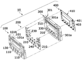
- FIG. 2 is an exploded perspective view showing a configuration of a capacitive sensing touch switch according to the present invention
- Figure 3 is a side view showing the electrostatic conductor of the capacitive sensing touch switch according to the present invention
- Figure 4 is a perspective view showing the appearance of the capacitive sensing touch switch according to the invention the combination is completed
- FIG. 5 is a front view of the capacitive sensing touch switch of the present invention.
- FIG. 6 is an exploded perspective view showing another embodiment of the capacitive sensing touch switch according to the present invention.
- the capacitive sensing touch switch 10 (hereinafter referred to as a “touch switch”) according to the present invention includes a cover panel 100, an electrostatic panel 200, and a support panel 300. And control board 400 is roughly divided.
- the cover panel 100 is typically made of a non-conductive material, that is, plastic (PC: Poly Carbonate) material among plastic, glass, ceramic, and wood, and a plurality of touch buttons 110 to contact the human body on its surface.
- the cover panel 100 is provided with a plurality of first coupling members 101 to be coupled to the second coupling member 301 of the support panel 300 to be described later.
- the cover panel 100 completely prints the entire surface of the transparent synthetic resin in a predetermined color, and then cuts only the touch button 110 into a shape ("A" display area) as shown in FIG. It is preferable to facilitate light transmission of the light emitter 401 provided on the control substrate 400.
- the touch button 110 is integrated with the cover panel 100 in which any one of the soft transparent synthetic resin, that is, the soft synthetic resin, such as polyurethane or rubber, is integrated.
- the soft transparent synthetic resin that is, the soft synthetic resin, such as polyurethane or rubber.
- the method of integrally forming the cover panel 100 made of the PC material and the touch button 110 made of the soft synthetic resin is possible by double injection.
- Double injection is a method of injecting a combination of two kinds of resins to form a single part.
- Two sets of molds are installed in an injection molding machine, and a first molded product (for example, a cover panel) is formed in the first mold. ), And then the secondary resin is injected into the cavity of the secondary mold and the primary molded product space so that the primary molded product can be molded secondly.
- a first molded product for example, a cover panel
- the cover panel 100 according to the present invention may be molded first, and the touch button 110 made of a soft synthetic resin may be molded second to form an integrated structure.
- At least one of the first coupling member 101 is provided in at least one edge portion of the cover panel 100 is formed in a substantially rectangular shape, the incision portion (101a) is formed on both sides.
- cut-out portion 101a is formed in the center of the first coupling member 101.
- the cover panel 100 may be formed in a flat or non-planar according to the installation of the electronic device, in the present embodiment will be described with reference to the embodiment formed of a curved surface having a predetermined curvature.
- a knob (Knob) 130 is provided inside the cover panel 100 to facilitate coupling with the electrostatic panel 200 to be described later.
- the electrostatic panel 200 is provided at the rear of the cover panel 100.
- the electrostatic panel 200 made of PC material has a writing hole 210 formed at a position opposite to the touch button 110.
- the writing hole 210 is formed to facilitate the transmission of light emitted from the light emitter 401 of the control substrate 400 to be described later.
- the bar-shaped electrostatic conductor 230 is integrally provided in a horizontal direction with respect to the adjacent one side orthogonal direction of each writing hole 210, that is, the illustrated direction.
- the electrostatic conductor 230 is formed integrally with the above-described electrostatic panel 200, the material is made of ABS resin to facilitate the plating of the conductor, unlike the electrostatic panel 200 made of a PC (Poly Carbonate) material.
- ABS resin is a generic name of impact resistant thermoplastic resin composed of three components such as acrylonitrile, butadiene and styrene, and is called ABS resin by taking the three letters of the head letters.
- ABS resins have improved mechanical strength, heat resistance, oil resistance, weather resistance, etc. while maintaining excellent permeability, workability, and electrical properties, and are optimized for the transfer characteristics of capacitance in the operation described later.
- the electrostatic conductor 230 made of ABS resin can be formed integrally with the electrostatic panel 200 made of PC resin by the above-described double injection. , No further explanation)
- the electrostatic conductor 230 integrally formed with a coating material made of any one of nickel (Ni), chromium (Cr), or gold (Au) was coated to maximize capacitance transfer.
- the electrostatic conductor 230 is not only the ABS resin but also a metal having excellent electrical conductivity, that is, silver (Ag), iron (Fe), aluminum (Al), stainless (STS), copper (Cu), and lead.
- the conductive metal of any one of (Pb) and gold (Au) may be formed integrally with the above-mentioned electrostatic panel 200.
- the method of integrally forming the electrostatic panel 200 made of PC resin and the electrostatic conductor 230 made of a conductive metal may be possible through an insert injection method.
- Insert injection is a molding method of integrating heterogeneous or heterogeneous synthetic resins or parts other than synthetic resins (metal, wood, paper, cloth, etc.) in a mold, particularly in the case of products integrated with metal.
- synthetic resins metal, wood, paper, cloth, etc.
- Insert injection is a molding method of integrating heterogeneous or heterogeneous synthetic resins or parts other than synthetic resins (metal, wood, paper, cloth, etc.) in a mold, particularly in the case of products integrated with metal.
- metal metal, wood, paper, cloth, etc.
- the electrostatic conductor 230 according to the present invention, as shown in Figure 3, double injection of ABS resin with the electrostatic panel 200, or through the electrostatic panel 200 and the insert injection method of excellent conductivity metal It can be formed integrally, regardless of the planar or curved surface of the electrostatic panel 200, the end of the electrostatic conductor 230 is formed to coincide with the same line in the vertical direction, the capacitance is a constant function in the operation described below .
- the electrostatic panel 200 is formed with a knob insertion hole 240 to be coupled to the knob 130 provided in the cover panel 100 described above.
- the support panel 300 is provided at the rear of the electrostatic panel 200 having such a configuration, and the support panel 300 includes a second coupling member 301, a writing hole 310, and a through hole 330. Prepared.
- the second coupling member 301 is a projection 301a formed in a right triangle shape in which an inclination that increases from one side to the other in cross section is formed, and the coupling hole of the first coupling member 101 of the cover panel 100 described above ( It is easy to insert into 101a), but it is the structure which prevents arbitrary disassembly after insertion is completed.
- the support panel 300 is a writing hole 310 is formed in a position opposite to the writing hole 210 of the electrostatic panel 200 described above, the one side adjacent to the writing hole 310 the above-described electroconductor
- the through hole 330 is formed to penetrate 230.
- the control substrate 400 is provided at the rear of the support panel 300, and the control substrate 400 includes a light emitter 401 and a sensing means 410.
- the light emitter 401 is an LED light, and is provided to the touch buttons 110 provided in the cover panel 100 through the lighting holes 210 and 310 formed in the electrostatic panel 200 and the support panel 300, respectively. It is provided to shine light.
- a through hole 403 is formed at one side adjacent to the light emitter 401 so that the electrostatic conductor 230 can pass therethrough.
- One or more sensing means 410 connected to each end of the electrostatic conductor 230 penetrating the through hole 403 are provided on the rear surface of the light emitter 401.
- the sensing means 410 is a capacitive touch sensor.
- the dielectric constant of the electroconductor 230 is changed by touching or touching a conductor such as a user's finger to the touch button 110, the capacitance change according to the dielectric constant change.
- the capacitance change according to the dielectric constant change.
- control board 400 is mounted on the rear surface of the supporting panel 300, and the end of each of the electrostatic conductors 230 protruding through the through hole 403 of the control board 400 is formed.
- sensing means 410 When connected to one or more sensing means 410 is provided, as shown in Figure 4, the assembly is completed.
- the electrostatic conductor 230 integrally provided in the electrostatic panel 200 is generated in the human body. Will cause a change in permittivity.
- the sensing means 410 which is a capacitive sensing sensor connected to the electrostatic conductor 230, changes the capacitance according to the above-described dielectric constant change so that the user's finger, which is a conductor, touches the touch switch 110. Is detected and a switching signal is generated in accordance with the detection signal.
- the sensing means 410 detects a change in capacitance, outputs a corresponding signal, and controls the operation of an electronic device (not shown).
- the electrostatic conductor 230 is integrally formed on the touch button 110 of the cover panel 100, and the cover panel ( 100 and the support panel 300 and the control substrate 400, as shown to be made of a configuration, the touch switch 10 made in such a configuration can also achieve the desired purpose according to the present invention, of course. .
- a touch switch of an electronic device capable of accurately detecting a change in capacitance even when the electronic device is used for a long time.
- the front cover panel provides a touch switch structure that can detect a constant change in electrostatic regardless of curved surface or plane.
Landscapes
- Switches That Are Operated By Magnetic Or Electric Fields (AREA)
- Engineering & Computer Science (AREA)
- General Engineering & Computer Science (AREA)
- Theoretical Computer Science (AREA)
- Human Computer Interaction (AREA)
- Physics & Mathematics (AREA)
- General Physics & Mathematics (AREA)
Abstract
Description
Claims (10)
- 전자기기에 구비되는 터치 스위치(10)에 있어서,상기 터치스위치(10)는;전면에 다수의 터치버튼(110)이 구비되며, 테두리의 각 변에는 적어도 하나 이상의 제 1결합부재(101)가 구비된 커버판넬(100)과;상기 커버판넬(100)의 후면에 구비되고, 상기 터치버튼(110)과 대향하는 위치에 형성된 라이팅 홀(210)과, 상기 라이팅 홀(210)에 인접한 일측 직각방향으로 정전도체(230)가 일체로 구비된 정전판넬(200)과;상기 커버판넬(100) 테두리에 마련된 제 1결합부재(101)와 대향하는 위치인 테두리에 제 2결합부재(301)가 구비되며, 상기 정전판넬(200)의 라이팅 홀(210)과 대향하는 위치에 라이팅 홀(310)이 형성되고, 상기 라이팅 홀(310) 인근에 상기 정전도체(230)가 관통하도록 관통공(330)이 형성된 지지판넬(300)과;상기 지지판넬(300) 일측에 구비되며, 상기 지지판넬(300)에 형성된 라이팅 홀(310)과 대향하는 위치에 다수 구비된 발광체(401)와, 상기 발광체(401)에 인접하는 일측에 상기 정전도체(230)가 지날수 있도록 관통공(403)이 형성되고, 상기 발광체(401)의 이면에는 상기 관통공(403)을 관통한 정전도체(230)의 각 단부와 연결된 하나 이상의 감지수단(410)이 구비된 컨트롤기판(400)을 포함하는 것을 특징으로 하는 정전용량 감지형 터치스위치.
- 제 1항에 있어서,상기 커버판넬(100)의 전면은, 곡면 또는 평면중 어느 하나로 형성된 것을 특징으로 하는 정전용량 감지형 터치스위치.
- 제 1항에 있어서,상기 제 1결합부재(101)는, 중심에 사각형상의 결합공(101b)이 형성되고, 상기 제 2결합부재(301)는 상기 제 1결합부재(101)의 결합공(101b)에 삽입, 결합되는 돌기(301a)로 이루어진 것을 특징으로 하는 정전용량 감지형 터치스위치.
- 제 3항에 있어서,상기 돌기(301a)는, 상기 결합공(101b)에 삽입이 용이하도록, 단면상 일측에서 타측으로 갈 수록 높아지는 경사가 형성되는 직각 삼각형인 것을 특징으로 하는 정전용량 감지형 터치스위치.
- 제 1항에 있어서,상기 제 1결합부재(101)는, 상기 제 2결합부재(301)와 해체가 용이하도록 양측에 절개부(101a)가 더 형성된 것을 특징으로 하는 정전용량 감지형 터치스위치.
- 제 1항에 있어서,상기 커버판넬(100)은, 투명성 재질의 전면을 인쇄한 후, 빛이 투과할 수 있도록 상기 터치버튼(110) 부위를 레이져로 깎아 내어 어두운 환경에서도 인식이 용이하도록 한 것을 특징으로 하는 정전용량 감지형 터치스위치.
- 제 1항에 있어서,상기 커버판넬(100)의 터치버튼(110)은, 연질 투명성 합성수지 상부에 문양을 인쇄한 것을 특징으로 하는 정전용량 감지형 터치스위치.
- 제 1항에 있어서,상기 정전판넬(200)은, PC수지로 이루어지며, 상기 정전판넬(200)의 직각방향으로 다수 구비된 정전도체(230)는 ABS수지 표면에 전도성 물질을 도금한 것을 특징으로 하는 정전용량 감지형 터치스위치.
- 제 1항에 있어서,상기 정전도체(230)는, 은(Ag), 철(Fe), 알루미늄(Al), 스테인레스(STS), 구리(Cu), 납(Pb), 금(Au)중 어느 하나로 이루어진 전도성 금속인 것을 특징으로 하는 정전용량 감지형 터치스위치.
- 제 1항에 있어서,상기 정전판넬(200)은, 전면이 곡면 또는 평면이라 하더라도, 상기 정전도체(230)의 끝단은 동일선상에 구비됨으로서, 상기 컨트롤기판(400)에 구비된 감지수단(410)에 정전용량이 동일하게 전달되는 것을 특징으로 하는 정전용량 감지형 터치스위치.
Priority Applications (4)
| Application Number | Priority Date | Filing Date | Title |
|---|---|---|---|
| JP2014527088A JP5960825B2 (ja) | 2012-05-25 | 2012-09-05 | 静電容量感知型タッチスイッチ |
| EP12877229.0A EP2858247B1 (en) | 2012-05-25 | 2012-09-05 | Capacitance-sensitive touch switch |
| US14/131,355 US9595961B2 (en) | 2012-05-25 | 2012-09-05 | Capacitance-sensitive touch switch |
| CN201280073312.4A CN104521144B (zh) | 2012-05-25 | 2012-09-05 | 电容敏感触摸开关 |
Applications Claiming Priority (4)
| Application Number | Priority Date | Filing Date | Title |
|---|---|---|---|
| KR10-2012-0056032 | 2012-05-25 | ||
| KR20120056032 | 2012-05-25 | ||
| KR10-2012-0073319 | 2012-07-05 | ||
| KR1020120073319A KR101183144B1 (ko) | 2012-05-25 | 2012-07-05 | 정전용량 감지형 터치 스위치 |
Publications (1)
| Publication Number | Publication Date |
|---|---|
| WO2013176343A1 true WO2013176343A1 (ko) | 2013-11-28 |
Family
ID=47113571
Family Applications (1)
| Application Number | Title | Priority Date | Filing Date |
|---|---|---|---|
| PCT/KR2012/007135 WO2013176343A1 (ko) | 2012-05-25 | 2012-09-05 | 정전용량 감지형 터치 스위치 |
Country Status (6)
| Country | Link |
|---|---|
| US (1) | US9595961B2 (ko) |
| EP (1) | EP2858247B1 (ko) |
| JP (1) | JP5960825B2 (ko) |
| KR (1) | KR101183144B1 (ko) |
| CN (1) | CN104521144B (ko) |
| WO (1) | WO2013176343A1 (ko) |
Families Citing this family (17)
| Publication number | Priority date | Publication date | Assignee | Title |
|---|---|---|---|---|
| KR101507111B1 (ko) * | 2013-06-28 | 2015-03-30 | 실력산업 (주) | 터치스위치 |
| KR101507110B1 (ko) * | 2013-06-28 | 2015-03-30 | 실력산업 (주) | 진동모터를 갖춘 정전 용량 감지형 터치 스위치 |
| KR101521581B1 (ko) * | 2013-06-28 | 2015-05-21 | 실력산업 (주) | 정전도체 착탈식 컨트롤기판을 갖춘 터치스위치 |
| JP6666712B2 (ja) * | 2015-12-25 | 2020-03-18 | ミネベアミツミ株式会社 | センサ装置、センサユニット、物品選択装置、物品選択ユニット及び自動販売機 |
| KR102416688B1 (ko) * | 2016-01-06 | 2022-07-05 | 엘지전자 주식회사 | 식기세척기 |
| DE102016102392A1 (de) * | 2016-02-11 | 2017-08-17 | Valeo Schalter Und Sensoren Gmbh | Bedienvorrichtung für ein Kraftfahrzeug mit kapazitiver Annäherungssensorik sowie Kraftfahrzeug |
| JP6522229B2 (ja) * | 2016-03-01 | 2019-05-29 | 三菱電機株式会社 | 静電容量式タッチパネル |
| KR101796991B1 (ko) | 2016-03-04 | 2017-11-13 | 현대자동차주식회사 | 차량 및 그 제어방법 |
| DE102017200595A1 (de) * | 2016-11-15 | 2018-05-17 | Volkswagen Aktiengesellschaft | Vorrichtung mit berührungsempfindlicher Freiformfläche und Verfahren zu deren Herstellung |
| KR101883080B1 (ko) * | 2016-12-20 | 2018-07-30 | 인탑스 주식회사 | 내장재 및 그 제조방법 |
| JP6755025B2 (ja) * | 2017-01-10 | 2020-09-16 | 株式会社Nsc | カバーガラスおよびタッチパネル装置 |
| DE102017000159A1 (de) * | 2017-01-11 | 2018-07-12 | GM Global Technology Operations LLC (n. d. Ges. d. Staates Delaware) | Bedienelement für ein Kraftfahrzeug |
| JP6544536B2 (ja) * | 2017-05-31 | 2019-07-17 | 株式会社Nsc | タッチスイッチ |
| KR102717749B1 (ko) * | 2019-08-14 | 2024-10-14 | 엘지전자 주식회사 | 터치센서용 터치윈도우 및 이를 포함하는 가전제품 |
| JP7195242B2 (ja) * | 2019-10-08 | 2022-12-23 | 日立グローバルライフソリューションズ株式会社 | 洗濯機 |
| KR102307774B1 (ko) * | 2020-02-25 | 2021-10-01 | 주식회사 모베이스전자 | 차량용 터치 스위치 및 그 제어방법 |
| KR102738192B1 (ko) | 2024-06-04 | 2024-12-04 | 주식회사 에이이엠모빌리티 | 햅틱 진동모듈이 적용된 차량용 터치스위치 컨트롤러 |
Citations (5)
| Publication number | Priority date | Publication date | Assignee | Title |
|---|---|---|---|---|
| US20010048247A1 (en) * | 2000-06-01 | 2001-12-06 | Lg Electronics Inc. | Touch switching apparatus |
| KR20020086405A (ko) * | 2002-08-05 | 2002-11-18 | 주식회사 이에스에스디 | 전기 기기용 간접 터치 스위치 |
| US20060131159A1 (en) * | 2004-12-17 | 2006-06-22 | Diehl Ako Stiftung & Co., Kg | Capacitive touch switch |
| US20070103451A1 (en) * | 2005-11-09 | 2007-05-10 | Diehl Ako Stiftung & Co. Kg | Capacitive touch switch |
| KR20110094568A (ko) | 2010-02-17 | 2011-08-24 | 문명일 | 정전용량 감지형 터치스위치 |
Family Cites Families (10)
| Publication number | Priority date | Publication date | Assignee | Title |
|---|---|---|---|---|
| JP2005196605A (ja) * | 2004-01-09 | 2005-07-21 | Shotatsu Kagi Kofun Yugenkoshi | タッチコントロール入力モジュール及び該タッチコントロール入力モジュールを具有するハンドサイズの電子設備 |
| US7295190B2 (en) * | 2004-05-21 | 2007-11-13 | Harald Philipp | Touch sensitive control panel |
| DE102005029503A1 (de) * | 2005-06-24 | 2006-12-28 | Siemens Ag | Bedienelement mit Näherungssensor und Abschirmung |
| DE102007050654B4 (de) * | 2007-10-24 | 2015-06-18 | Diehl Ako Stiftung & Co. Kg | Kapazitiver Berührungsschalter |
| JP2009244008A (ja) * | 2008-03-31 | 2009-10-22 | Omron Corp | センサヘッド |
| KR20110085166A (ko) * | 2010-01-19 | 2011-07-27 | 주식회사 신창전기 | 차량용 터치 스위치 장치 |
| KR20110094571A (ko) | 2010-02-17 | 2011-08-24 | 문명일 | 정전용량 감지형 터치스위치 |
| JP5610467B2 (ja) * | 2010-03-15 | 2014-10-22 | 株式会社タニタ | 静電容量型スイッチ及びそれを備える重量測定装置、並びに静電容量型スイッチの調整方法 |
| DE102010013947B4 (de) * | 2010-04-06 | 2017-10-12 | Continental Automotive Gmbh | Kapazitiver Annäherungssensor |
| JP5476263B2 (ja) * | 2010-09-17 | 2014-04-23 | 小島プレス工業株式会社 | 車室内照明装置 |
-
2012
- 2012-07-05 KR KR1020120073319A patent/KR101183144B1/ko active IP Right Grant
- 2012-09-05 US US14/131,355 patent/US9595961B2/en active Active
- 2012-09-05 JP JP2014527088A patent/JP5960825B2/ja active Active
- 2012-09-05 EP EP12877229.0A patent/EP2858247B1/en active Active
- 2012-09-05 WO PCT/KR2012/007135 patent/WO2013176343A1/ko active Application Filing
- 2012-09-05 CN CN201280073312.4A patent/CN104521144B/zh active Active
Patent Citations (5)
| Publication number | Priority date | Publication date | Assignee | Title |
|---|---|---|---|---|
| US20010048247A1 (en) * | 2000-06-01 | 2001-12-06 | Lg Electronics Inc. | Touch switching apparatus |
| KR20020086405A (ko) * | 2002-08-05 | 2002-11-18 | 주식회사 이에스에스디 | 전기 기기용 간접 터치 스위치 |
| US20060131159A1 (en) * | 2004-12-17 | 2006-06-22 | Diehl Ako Stiftung & Co., Kg | Capacitive touch switch |
| US20070103451A1 (en) * | 2005-11-09 | 2007-05-10 | Diehl Ako Stiftung & Co. Kg | Capacitive touch switch |
| KR20110094568A (ko) | 2010-02-17 | 2011-08-24 | 문명일 | 정전용량 감지형 터치스위치 |
Also Published As
| Publication number | Publication date |
|---|---|
| US20160072504A1 (en) | 2016-03-10 |
| JP2014527271A (ja) | 2014-10-09 |
| CN104521144A (zh) | 2015-04-15 |
| EP2858247B1 (en) | 2019-01-23 |
| EP2858247A1 (en) | 2015-04-08 |
| KR101183144B1 (ko) | 2012-09-14 |
| JP5960825B2 (ja) | 2016-08-02 |
| CN104521144B (zh) | 2018-07-06 |
| US9595961B2 (en) | 2017-03-14 |
| EP2858247A4 (en) | 2016-01-27 |
Similar Documents
| Publication | Publication Date | Title |
|---|---|---|
| WO2013176343A1 (ko) | 정전용량 감지형 터치 스위치 | |
| US10581430B2 (en) | Backlighting appliance deadfronted user interfaces | |
| KR100346266B1 (ko) | 평판형 발광소자를 백라이트로 이용한 터치 스위치 장치 | |
| US7923654B2 (en) | Capacitive touch switch and domestic appliance provided with such switch | |
| WO2011105701A2 (ko) | 터치 센서 | |
| WO2011149199A2 (ko) | 금속박막을 이용한 터치패널 및 그 제조방법 | |
| CN103001623A (zh) | 触摸开关 | |
| WO2017073954A1 (ko) | 터치 스위치 유니트 및 이를 구비하는 차량 실내 조명 장치 | |
| WO2011007937A1 (en) | Call button assembly for elevator | |
| WO2011115403A2 (ko) | 터치센서 조립체 및 그 제조방법 | |
| CN105075121B (zh) | 用于咖啡机的操作单元 | |
| WO2013077578A1 (ko) | 터치패널센서 | |
| US11445621B2 (en) | Electric-heating apparatus and touch device therein | |
| KR101314527B1 (ko) | 정전용량 감지형 터치 스위치 | |
| EP1894712A1 (en) | Touch sensitive foil and a switch made thereof | |
| WO2012047033A2 (ko) | 내구성이 강하며 터치감을 주는 기계식 키의 구조 | |
| WO2017010676A1 (ko) | 키보드 및 그 제조방법 | |
| TWI739073B (zh) | 電熱設備及其觸控裝置 | |
| KR101521581B1 (ko) | 정전도체 착탈식 컨트롤기판을 갖춘 터치스위치 | |
| CN210327530U (zh) | 一种电容式触控按键和电磁加热装置 | |
| CN106921378A (zh) | 触控按键模组及移动终端 | |
| CN110992568A (zh) | 一种图案解锁装置 | |
| WO2017200270A1 (ko) | 정전식 스위치 | |
| KR20200070742A (ko) | 정전용량방식 조광형 터치입력부가 포함된 작동판넬 | |
| KR980003973A (ko) | 방향성을 갖는 키패드를 구비한 키보드시스템 |
Legal Events
| Date | Code | Title | Description |
|---|---|---|---|
| ENP | Entry into the national phase |
Ref document number: 2014527088 Country of ref document: JP Kind code of ref document: A |
|
| 121 | Ep: the epo has been informed by wipo that ep was designated in this application |
Ref document number: 12877229 Country of ref document: EP Kind code of ref document: A1 |
|
| WWE | Wipo information: entry into national phase |
Ref document number: 14131355 Country of ref document: US |
|
| WWE | Wipo information: entry into national phase |
Ref document number: 2012877229 Country of ref document: EP |
|
| NENP | Non-entry into the national phase |
Ref country code: DE |