WO2013172324A1 - 走行環境検出装置、及び、走行環境検出プログラム - Google Patents
走行環境検出装置、及び、走行環境検出プログラム Download PDFInfo
- Publication number
- WO2013172324A1 WO2013172324A1 PCT/JP2013/063368 JP2013063368W WO2013172324A1 WO 2013172324 A1 WO2013172324 A1 WO 2013172324A1 JP 2013063368 W JP2013063368 W JP 2013063368W WO 2013172324 A1 WO2013172324 A1 WO 2013172324A1
- Authority
- WO
- WIPO (PCT)
- Prior art keywords
- light source
- vehicle
- detection device
- environment detection
- captured image
- Prior art date
- Legal status (The legal status is an assumption and is not a legal conclusion. Google has not performed a legal analysis and makes no representation as to the accuracy of the status listed.)
- Ceased
Links
Images


Classifications
-
- G—PHYSICS
- G01—MEASURING; TESTING
- G01J—MEASUREMENT OF INTENSITY, VELOCITY, SPECTRAL CONTENT, POLARISATION, PHASE OR PULSE CHARACTERISTICS OF INFRARED, VISIBLE OR ULTRAVIOLET LIGHT; COLORIMETRY; RADIATION PYROMETRY
- G01J1/00—Photometry, e.g. photographic exposure meter
- G01J1/42—Photometry, e.g. photographic exposure meter using electric radiation detectors
- G01J1/4257—Photometry, e.g. photographic exposure meter using electric radiation detectors applied to monitoring the characteristics of a beam, e.g. laser beam, headlamp beam
-
- B—PERFORMING OPERATIONS; TRANSPORTING
- B60—VEHICLES IN GENERAL
- B60Q—ARRANGEMENT OF SIGNALLING OR LIGHTING DEVICES, THE MOUNTING OR SUPPORTING THEREOF OR CIRCUITS THEREFOR, FOR VEHICLES IN GENERAL
- B60Q1/00—Arrangement of optical signalling or lighting devices, the mounting or supporting thereof or circuits therefor
- B60Q1/02—Arrangement of optical signalling or lighting devices, the mounting or supporting thereof or circuits therefor the devices being primarily intended to illuminate the way ahead or to illuminate other areas of way or environments
- B60Q1/04—Arrangement of optical signalling or lighting devices, the mounting or supporting thereof or circuits therefor the devices being primarily intended to illuminate the way ahead or to illuminate other areas of way or environments the devices being headlights
- B60Q1/14—Arrangement of optical signalling or lighting devices, the mounting or supporting thereof or circuits therefor the devices being primarily intended to illuminate the way ahead or to illuminate other areas of way or environments the devices being headlights having dimming means
- B60Q1/1415—Dimming circuits
- B60Q1/1423—Automatic dimming circuits, i.e. switching between high beam and low beam due to change of ambient light or light level in road traffic
-
- G—PHYSICS
- G08—SIGNALLING
- G08G—TRAFFIC CONTROL SYSTEMS
- G08G1/00—Traffic control systems for road vehicles
- G08G1/16—Anti-collision systems
- G08G1/166—Anti-collision systems for active traffic, e.g. moving vehicles, pedestrians, bikes
-
- B—PERFORMING OPERATIONS; TRANSPORTING
- B60—VEHICLES IN GENERAL
- B60Q—ARRANGEMENT OF SIGNALLING OR LIGHTING DEVICES, THE MOUNTING OR SUPPORTING THEREOF OR CIRCUITS THEREFOR, FOR VEHICLES IN GENERAL
- B60Q2300/00—Indexing codes for automatically adjustable headlamps or automatically dimmable headlamps
- B60Q2300/30—Indexing codes relating to the vehicle environment
- B60Q2300/31—Atmospheric conditions
- B60Q2300/314—Ambient light
Definitions
- the present invention relates to a traveling environment detection device that detects an environment in which a vehicle travels, and a traveling environment detection program.
- a technique for detecting a light source (a headlight, a tail lamp, etc.) of a vehicle using an image sensor for detecting surrounding vehicles is known.
- a light source and reflected light from a road surface of light emitted from the light source are detected in a captured image, one that identifies the light source as a vehicle light source is known (for example, , See Patent Document 1).
- an object of the present invention is to make it possible to accurately detect a traveling environment in a traveling environment detection device that detects an environment in which the vehicle travels and a traveling environment detection program.
- the image acquisition unit acquires a captured image obtained by imaging the outside of the vehicle
- the parameter extraction unit selects a road surface on the road on which the vehicle is traveling from the captured image. Extract parameters related to brightness.
- the traveling environment estimation means estimates the traveling environment of the host vehicle based on the parameter.
- the driving environment is obtained by using a parameter based on the brightness of the road surface, not the brightness of the entire captured image or the brightness of the sky, because the road surface has few light sources and is affected by a specific light source. This is because the brightness can be accurately obtained without any problem.
- asphalt that is widely used on the road surface tends to have a brightness according to the average brightness of the surroundings, and the brightness of the surroundings is calculated based on the brightness of the entire captured image and the brightness of the sky. This is because the brightness of the surroundings can be detected more accurately.
- the ambient brightness can be detected more accurately by estimating the traveling environment according to the parameter relating to the brightness of the road surface. Therefore, it is possible to accurately detect the traveling environment according to the ambient brightness.
- the light source is extracted by using the light source extraction means for extracting the light source from the captured image and the accuracy information in which the accuracy as the light source of the vehicle is associated with the position in the captured image.
- Light source determination means for determining whether or not the light source of the vehicle, and accuracy change means for changing the correspondence between the position in the captured image in the accuracy information and the accuracy that is the light source of the vehicle according to the estimated traveling environment; , May be provided.
- the accuracy information can be changed according to the travel environment, so that it is appropriately determined for each travel environment whether the light source in the captured image is the light source of the vehicle. Can do.
- a computer may be a running environment detection program for causing a computer to function as each means constituting the running environment detection device.
- FIG. 1 is a block diagram showing a schematic configuration of a traveling environment detection device 1 to which the present invention is applied.
- 4 is a flowchart illustrating a write control process executed by a processing unit 10. It is a flowchart which shows the driving
- (A) is a figure which shows the area
- (b) is a figure which shows the weight set with respect to a driving
- the traveling environment detection device 1 shown in FIG. 1 is mounted on a vehicle such as a passenger car, for example, and there is another vehicle around the host vehicle (specifically, the headlight of the host vehicle may cause glare). When there is another vehicle in the range), the direction of the optical axis of the headlight of the host vehicle is changed downward to have a light control system function to prevent dazzling.
- the traveling environment detection device 1 detects the environment (traveling environment) in which the host vehicle travels when detecting another vehicle, and changes the setting when determining the light source according to the traveling environment. It has a function of improving the light source discrimination accuracy.
- the traveling environment detection device 1 includes a processing unit 10, a camera 20, a speed sensor 21, a rudder angle sensor 22, and a light control unit 30.
- the camera 20 is configured as a color camera that captures the traveling direction of the vehicle (particularly forward) in color, and sends the captured image to the processing unit 10.
- the camera 20 is arranged so that at least the irradiation range by the headlight is included in the imaging range.
- the speed sensor 21 and the rudder angle sensor 22 have a well-known configuration and are used for estimating the traveling direction of the vehicle.
- the speed sensor 21 and the rudder angle sensor 22 send detection results by themselves to the processing unit 10.
- the light control unit 30 receives the switching command for switching the vehicle light to be turned on from the processing unit 10 and controls the irradiation range by the headlight. At this time, the light control unit 30 changes the irradiation area of the headlight so that the light source is not included in the irradiation area.
- the light control unit 30 changes the irradiation range by switching the vehicle light to be lit from a high beam (travel light) to a low beam (passing light).
- the configuration may be such that the direction of the optical axis is moved in a direction in which no other vehicle exists (for example, downward or leftward) in accordance with a command from the processing unit 10.
- the processing unit 10 is configured as a well-known microcomputer including a CPU and a memory 11 such as a ROM and a RAM, and will be described later based on a program (including a vehicle light source detection program) stored in the memory 11. Various processes such as a write control process are performed. Further, the memory 11 includes parameters indicating characteristics of the lights of the vehicle (including values corresponding to parameters such as position, size, color, height, distance between paired lights, behavior, etc.), vehicle The parameter which shows the characteristic of light sources other than is stored. The parameters stored in the memory 11 are used when a light source indicating a vehicle light is identified and detected from a captured image in a light source other than the vehicle light.
- the light control process is a process for controlling the direction of the optical axis of the headlight by identifying and detecting the light source indicating the vehicle light from the captured image.
- the light control process is a process that is started when the vehicle is turned on, and thereafter executed every predetermined period (for example, every 100 ms). Specifically, as shown in FIG. 2, first, an image captured by the camera 20 is acquired (S110).
- the travel environment estimation process is a process for estimating the travel environment of the host vehicle based on the brightness of the road surface. Specifically, as shown in FIG. 3A, first, a white line as a lane marking is detected (S210). In this process, a known white line detection technique or the like is used to detect a white line in the captured image. Subsequently, the brightness of the road surface is detected (S220). In this process, the road surface area is specified on the assumption that the detected white line is a boundary line that divides the inside and outside of the travel section (travel area). For example, when white lines existing on the left and right sides of the travel area of the host vehicle are detected, an area inside the white line that does not include these white lines is set as a road surface area.
- the brightness of the road surface is detected by calculating the average brightness of the specified road surface area.
- the brightness at a specific position (arbitrary part) on the road surface may be the brightness of the road surface.
- the detection result of the road surface brightness is held in the memory 11 for a certain time (for example, 20 times).
- the road surface brightness detected before the previous time is read out, and the time series analysis is performed based on the time series data of the road surface brightness.
- the change rate of the brightness of the road surface time change rate such as time differentiation
- the change cycle are detected (S230).
- the driving environment is discriminated (estimated) using parameters relating to the road surface brightness such as the road surface brightness, the road surface brightness change rate, and the road surface brightness change cycle (S240).
- the brightness of the road surface (road surface)
- the instantaneous value, average time, integrated value for a predetermined time, basic value Lb (brightness of the road surface with a time change rate equal to or lower than the predetermined value), etc. are dark and the change cycle of the road brightness is long
- the amount of change in the brightness of the road surface is relatively small.
- the brightness of the road surface is bright, the change period of the road surface brightness may be short or long, or there may be no periodicity, and the change in the brightness of the road surface is relatively large There are features.
- tunnels are characterized in that the road surface is bright, the road brightness change cycle is short, and the change in road brightness is relatively small. Particularly in the tunnel, there is a feature that variation in variation (difference between maximum values of brightness and difference between minimum values) is reduced.
- the process returns to FIG. 2 to extract light source candidates (S130).
- a well-known method can be used for extracting light source candidates.
- the light source candidates are extracted by cutting out a continuous area having a predetermined luminance or a luminance difference from the surroundings. Further, in this process, the entire region as one light source in the captured image and including the smallest region is cut out in a rectangle (rectangle), and labeling (numbering) is performed for each cut out region. In this process, a larger area is extracted as the light source in the captured image is larger.
- vehicle light source discrimination processing is performed (S140).
- the light source is weighted according to the driving environment and the position of the light source in the captured image to determine whether the light source is derived from the vehicle, and the headlight switching time is set according to the driving environment. Set.
- the vehicle travels ahead of the host vehicle in the same direction as the oncoming vehicle approaching from the front of the host vehicle toward the host vehicle or the host vehicle.
- the preceding vehicle often exists in the traveling section and tends to decrease outside the traveling section.
- reflectors reflectors
- signboards signboards, and the like are rarely present in the traveling section and tend to increase outside the traveling section. For this reason, each area in the captured image is weighted in consideration of this tendency.
- the captured image is divided into a plurality of areas, and each divided area is weighted according to the driving environment (S310).
- the image is divided into a plurality of regions according to the position of the white line detected in the captured image.
- the area above the point at infinity in the captured image is defined as area A.
- area A the area above the point at infinity in the captured image (the intersection of a plurality of white line extensions, the position indicated by + in FIG. 6A) is defined as area A.
- area C the area on the left side of the front of the host vehicle.
- area D an area on the left side of area C is area B, and an area on the right side of area D is area E.
- the highest weighting is set with respect to the area C and the area D with the highest probability that a preceding vehicle and an oncoming vehicle exist.
- the probability that there is a small amount of traffic and there is a preceding vehicle is low, so a lower weight is set than when the driving environment is “city” or “tunnel”. .
- the traveling environment is “tunnel”, since the illumination of the tunnel is located in the area A, the weight is set to 0 in order to exclude this.
- the driving environment is “countryside”, the undulation is larger than in the urban area, and the probability that a vehicle is also present in the area A is higher.
- a light candidate feature amount is calculated, and it is determined whether the light source is a vehicle light source according to the feature amount (S320).
- the feature amount relating to the position is obtained by associating the position of the light source with the above-described weighting.
- a still image level feature value, a pair feature value, and a time-series feature value may be considered.
- the still image level feature amount represents a feature amount based on the color or shape of a single light source included in the light source
- the pair feature amount represents a feature amount based on the relationship with other light sources positioned in the horizontal direction
- the time-series feature amount represents It represents the feature value based on the result of tracking the light source.
- the accuracy that the light source is a vehicle light source is obtained according to each feature amount.
- the accuracy of the vehicle light source is calculated by taking a weighted average of each feature amount.
- each feature-value and the accuracy which is a vehicle light source may be matched experimentally beforehand.
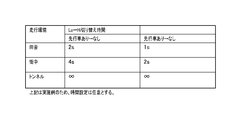
- the threshold value set in advance is compared with the accuracy of the vehicle light source, and the light source having the probability less than the threshold value is removed as a disturbance to determine the remaining light source as the vehicle light. Subsequently, a switching time indicating a time until the headlight is switched from the low beam of the headlight to the high beam according to the traveling environment is set according to the traveling environment (S330).
- the switching time is set shorter when the oncoming vehicle is no longer present than when the preceding vehicle is no longer present. This is because it is necessary to ensure visibility immediately after passing the oncoming vehicle.
- This process is a process of instructing the type of light to be turned on by the light control unit 30 according to the presence or absence of a preceding vehicle or an oncoming vehicle.
- the processing unit 10 acquires a captured image obtained by capturing the traveling direction of the host vehicle, and parameters relating to the brightness of the road surface on the road on which the host vehicle travels from the captured image. To extract. And based on this parameter, the traveling environment of the own vehicle is estimated.
- the ambient brightness can be detected more accurately by estimating the traveling environment in accordance with the parameter relating to the brightness of the road surface. Therefore, the traveling environment can be detected with high accuracy.
- the processing unit 10 extracts a light source from the captured image, and uses the accuracy information in which the accuracy that is the light source of the vehicle is associated with the position in the captured image. It is determined whether or not the light source is a vehicle. Then, the correspondence relationship between the position in the captured image in the accuracy information and the accuracy that is the light source of the vehicle is changed according to the estimated traveling environment.
- the accuracy information can be changed according to the traveling environment. Therefore, it is appropriately determined for each traveling environment whether or not the light source in the captured image is the light source of the vehicle. be able to.
- working environment detection apparatus 1 when it determines with a light source being a light source of a vehicle, the light control part which changes the irradiation area
- the headlight of the own vehicle can make it difficult for other vehicles to dazzle.
- other vehicles can be detected with high accuracy, it is possible to suppress malfunctions when changing the irradiation area of the headlight.
- the processing unit 10 extracts a white line drawn on the road surface from the captured image, and extracts a parameter relating to the brightness of the road surface in a region excluding the region including the white line in the captured image.
- the brightness of the road surface is determined by excluding the white line area in the captured image, so that the brightness of the road surface can be detected more accurately. Further, in the traveling environment detection device 1, the processing unit 10 changes the correspondence relationship in the accuracy information according to the position of the white line.
- the traveling environment detection device 1 by estimating the region where the other vehicle travels according to the position of the white line, the correspondence between the position in the captured image in the accuracy information and the accuracy that is the light source of the vehicle is appropriately set. Can be changed.
- the processing unit 10 extracts the average luminance of the road surface portion in the captured image as a parameter. According to the traveling environment detection device 1 as described above, it is possible to prevent erroneous detection of the brightness when the light source is applied to a part of the road surface as compared with the case where the brightness is detected from only a part of the road surface. it can.
- the processing unit 10 extracts the time change rate of the luminance of the road surface portion in the captured image as a parameter.
- the time change rate of the luminance of the road surface portion is detected, so that the luminance periodically changes like traveling in a tunnel, or as traveling in a city. It can be detected that the luminance changes aperiodically. In this way, it is possible to estimate a traveling environment such as a tunnel or a town according to the time change rate of luminance.
- Embodiments of the present invention are not limited to the above-described embodiments, and can take various forms as long as they belong to the technical scope of the present invention.
- the configuration for detecting the traveling environment is applied to the configuration for controlling the light, but the present invention can be similarly applied to other configurations for controlling the vehicle using the traveling environment.
- it may be configured to detect that the traveling environment is in a tunnel by the traveling environment estimation process and change the air conditioning to the inside air circulation.
- the speed sensor 21 and the steering angle sensor 22 were utilized in order to specify the advancing direction of a vehicle, if the advancing direction of a vehicle can be specified (estimated), it will not be restricted to this structure.
- the traveling direction of the vehicle can be specified by the speed displayed on the meter, the yaw rate signal, or the like.
- the vehicle light source information the accuracy that is the vehicle light source set for each traveling environment according to the position in the captured image is used, and based on this, the light source of the vehicle is discriminated from among the light sources. Not.
- the vehicle light source information is information related to the position in the captured image, but this is used for extraction instead of discrimination, and when the light source is extracted from the captured image, the search range in the captured image is set according to the driving environment. May be.
- vehicle light source feature information shape, etc.
- vehicle light source recognition processing discrimination processing
- the light control unit 30 corresponds to the irradiation region changing unit of the present invention. Furthermore, the process of S110 among the processes by the processing unit 10 corresponds to the image acquisition unit of the present invention, and the process of S130 corresponds to the light source extraction unit of the present invention.
- the process of S210 of the said embodiment is corresponded to the lane marking extraction means of this invention, and the process of S220, S230 is equivalent to the parameter extraction means of this invention.
- the process of S240 corresponds to the travel environment estimating means of the present invention
- the process of S310 corresponds to the accuracy changing means of the present invention
- the process of S320 corresponds to the light source determining means of the present invention.
- the process of S310 is corresponded to the vehicle light source information acquisition means of this invention, and the process of S130 and S320 is equivalent to a vehicle light source detection means.
- the traveling environment detection device does not have to be integrally configured as a device mounted on the vehicle, and for example, a part thereof may be mounted outside the vehicle via a network or the like.
Landscapes
- Physics & Mathematics (AREA)
- Engineering & Computer Science (AREA)
- Mechanical Engineering (AREA)
- General Physics & Mathematics (AREA)
- Optics & Photonics (AREA)
- Spectroscopy & Molecular Physics (AREA)
- Lighting Device Outwards From Vehicle And Optical Signal (AREA)
- Traffic Control Systems (AREA)
Priority Applications (1)
| Application Number | Priority Date | Filing Date | Title |
|---|---|---|---|
| US14/402,018 US9372112B2 (en) | 2012-05-18 | 2013-05-14 | Traveling environment detection device |
Applications Claiming Priority (2)
| Application Number | Priority Date | Filing Date | Title |
|---|---|---|---|
| JP2012114854A JP5884635B2 (ja) | 2012-05-18 | 2012-05-18 | 走行環境検出装置、走行環境検出プログラム、およびライト制御装置 |
| JP2012-114854 | 2012-05-18 |
Publications (1)
| Publication Number | Publication Date |
|---|---|
| WO2013172324A1 true WO2013172324A1 (ja) | 2013-11-21 |
Family
ID=49583729
Family Applications (1)
| Application Number | Title | Priority Date | Filing Date |
|---|---|---|---|
| PCT/JP2013/063368 Ceased WO2013172324A1 (ja) | 2012-05-18 | 2013-05-14 | 走行環境検出装置、及び、走行環境検出プログラム |
Country Status (3)
| Country | Link |
|---|---|
| US (1) | US9372112B2 (https=) |
| JP (1) | JP5884635B2 (https=) |
| WO (1) | WO2013172324A1 (https=) |
Cited By (1)
| Publication number | Priority date | Publication date | Assignee | Title |
|---|---|---|---|---|
| JP2017081500A (ja) * | 2015-10-30 | 2017-05-18 | 株式会社小糸製作所 | 車両用灯具システム |
Families Citing this family (7)
| Publication number | Priority date | Publication date | Assignee | Title |
|---|---|---|---|---|
| KR101610036B1 (ko) * | 2014-12-05 | 2016-04-07 | 현대모비스 주식회사 | 터널 판단 장치 및 터널 판단 방법 |
| JP6657925B2 (ja) * | 2015-06-04 | 2020-03-04 | ソニー株式会社 | 車載カメラ・システム並びに画像処理装置 |
| US10419723B2 (en) * | 2015-06-25 | 2019-09-17 | Magna Electronics Inc. | Vehicle communication system with forward viewing camera and integrated antenna |
| JP6527455B2 (ja) * | 2015-12-02 | 2019-06-05 | 株式会社Subaru | 車外環境認識装置 |
| CN107677365B (zh) * | 2017-10-19 | 2019-12-31 | 招商局重庆交通科研设计院有限公司 | 一种公路隧道照明亮度快速检测装置及方法 |
| KR102109841B1 (ko) * | 2018-11-30 | 2020-05-28 | 아주대학교 산학협력단 | 주행 영상으로부터 차량을 검출하는 방법 및 장치 |
| US11161450B2 (en) * | 2019-02-15 | 2021-11-02 | Robotic Research, Llc | Autonomous headlight control based on elevation profile |
Citations (6)
| Publication number | Priority date | Publication date | Assignee | Title |
|---|---|---|---|---|
| JPH1011582A (ja) * | 1996-06-20 | 1998-01-16 | Honda Motor Co Ltd | 車両の白線検出装置 |
| JP2005092861A (ja) * | 2003-08-11 | 2005-04-07 | Hitachi Ltd | 車両制御システム |
| JP2005201741A (ja) * | 2004-01-14 | 2005-07-28 | Denso Corp | 路面反射検出装置 |
| JP2008293116A (ja) * | 2007-05-22 | 2008-12-04 | Nippon Soken Inc | 車載用車両灯検出装置および車両用照明装置 |
| JP2010036757A (ja) * | 2008-08-06 | 2010-02-18 | Fuji Heavy Ind Ltd | 車線逸脱防止制御装置 |
| JP2010132053A (ja) * | 2008-12-03 | 2010-06-17 | Koito Mfg Co Ltd | 前照灯制御装置 |
Family Cites Families (6)
| Publication number | Priority date | Publication date | Assignee | Title |
|---|---|---|---|---|
| JP3612970B2 (ja) | 1997-11-07 | 2005-01-26 | 日産自動車株式会社 | トンネル検出装置及びそれを用いた車両制御装置 |
| JP4253271B2 (ja) | 2003-08-11 | 2009-04-08 | 株式会社日立製作所 | 画像処理システム及び車両制御システム |
| JP4496964B2 (ja) | 2005-01-14 | 2010-07-07 | 株式会社デンソー | 車両用トンネル検出装置および車両用ライト制御装置 |
| US20100020170A1 (en) * | 2008-07-24 | 2010-01-28 | Higgins-Luthman Michael J | Vehicle Imaging System |
| JP2010040001A (ja) | 2008-08-08 | 2010-02-18 | Toyota Motor Corp | 車両用衝突危険度判定システム、通信端末及び車載機 |
| JP2011143822A (ja) | 2010-01-14 | 2011-07-28 | Koito Mfg Co Ltd | 車両用前照灯の配光制御システム |
-
2012
- 2012-05-18 JP JP2012114854A patent/JP5884635B2/ja not_active Expired - Fee Related
-
2013
- 2013-05-14 US US14/402,018 patent/US9372112B2/en active Active
- 2013-05-14 WO PCT/JP2013/063368 patent/WO2013172324A1/ja not_active Ceased
Patent Citations (6)
| Publication number | Priority date | Publication date | Assignee | Title |
|---|---|---|---|---|
| JPH1011582A (ja) * | 1996-06-20 | 1998-01-16 | Honda Motor Co Ltd | 車両の白線検出装置 |
| JP2005092861A (ja) * | 2003-08-11 | 2005-04-07 | Hitachi Ltd | 車両制御システム |
| JP2005201741A (ja) * | 2004-01-14 | 2005-07-28 | Denso Corp | 路面反射検出装置 |
| JP2008293116A (ja) * | 2007-05-22 | 2008-12-04 | Nippon Soken Inc | 車載用車両灯検出装置および車両用照明装置 |
| JP2010036757A (ja) * | 2008-08-06 | 2010-02-18 | Fuji Heavy Ind Ltd | 車線逸脱防止制御装置 |
| JP2010132053A (ja) * | 2008-12-03 | 2010-06-17 | Koito Mfg Co Ltd | 前照灯制御装置 |
Cited By (1)
| Publication number | Priority date | Publication date | Assignee | Title |
|---|---|---|---|---|
| JP2017081500A (ja) * | 2015-10-30 | 2017-05-18 | 株式会社小糸製作所 | 車両用灯具システム |
Also Published As
| Publication number | Publication date |
|---|---|
| JP5884635B2 (ja) | 2016-03-15 |
| JP2013241065A (ja) | 2013-12-05 |
| US20150131086A1 (en) | 2015-05-14 |
| US9372112B2 (en) | 2016-06-21 |
Similar Documents
| Publication | Publication Date | Title |
|---|---|---|
| JP5884635B2 (ja) | 走行環境検出装置、走行環境検出プログラム、およびライト制御装置 | |
| US9415718B2 (en) | Vehicular headlight apparatus | |
| JP5692180B2 (ja) | 車両光源検出装置、ライト制御装置、および車両光源検出プログラム | |
| JP4702426B2 (ja) | 車両検出装置、車両検出プログラム、およびライト制御装置 | |
| US10286834B2 (en) | Vehicle exterior environment recognition apparatus | |
| US10442343B2 (en) | Vehicle exterior environment recognition apparatus | |
| JP5760884B2 (ja) | 車両の旋回予測装置 | |
| JP5573803B2 (ja) | ライト検出装置、ライト検出プログラム、およびライト制御装置 | |
| JP4743037B2 (ja) | 車両検出装置 | |
| JP6236039B2 (ja) | 車外環境認識装置 | |
| CN111976585B (zh) | 基于人工神经网络的投射信息识别装置及其方法 | |
| JP5962193B2 (ja) | 車両光源検出装置および車両光源検出プログラム | |
| JP2014024411A (ja) | 自発光光源検出装置、ライト制御装置、および自発光光源検出プログラム | |
| WO2017169704A1 (ja) | 環境認識装置 | |
| KR102135901B1 (ko) | 차량의 hba 제어시스템 및 제어방법 | |
| JP6132807B2 (ja) | レーンマーク認識装置 | |
| JP2006146754A (ja) | 先行車検出方法及び先行車検出装置 | |
| JP7035339B2 (ja) | ブレーキ判定方法及びブレーキ判定装置 | |
| JP5601300B2 (ja) | 車両の旋回予測装置 | |
| US12555390B2 (en) | Stop line recognition device | |
| CN119855738A (zh) | 配光控制系统及配光控制方法 | |
| JP6293570B2 (ja) | レーンマーク認識装置及び方法並びに車両 | |
| CN119559606A (zh) | 灯光检测方法、电子设备和存储介质 | |
| JP2020168957A (ja) | 移動支援システム、移動支援方法、及び移動支援プログラム |
Legal Events
| Date | Code | Title | Description |
|---|---|---|---|
| 121 | Ep: the epo has been informed by wipo that ep was designated in this application |
Ref document number: 13791226 Country of ref document: EP Kind code of ref document: A1 |
|
| NENP | Non-entry into the national phase |
Ref country code: DE |
|
| WWE | Wipo information: entry into national phase |
Ref document number: 14402018 Country of ref document: US |
|
| 122 | Ep: pct application non-entry in european phase |
Ref document number: 13791226 Country of ref document: EP Kind code of ref document: A1 |