WO2013171969A1 - Imaging optical system, imaging device - Google Patents
Imaging optical system, imaging device Download PDFInfo
- Publication number
- WO2013171969A1 WO2013171969A1 PCT/JP2013/002515 JP2013002515W WO2013171969A1 WO 2013171969 A1 WO2013171969 A1 WO 2013171969A1 JP 2013002515 W JP2013002515 W JP 2013002515W WO 2013171969 A1 WO2013171969 A1 WO 2013171969A1
- Authority
- WO
- WIPO (PCT)
- Prior art keywords
- lens
- optical system
- refractive index
- imaging optical
- imaging
- Prior art date
Links
- 230000003287 optical effect Effects 0.000 title claims abstract description 179
- 238000003384 imaging method Methods 0.000 title claims abstract description 137
- 230000004075 alteration Effects 0.000 claims abstract description 50
- 238000012937 correction Methods 0.000 claims abstract description 21
- 238000009826 distribution Methods 0.000 claims description 98
- 238000001514 detection method Methods 0.000 claims description 16
- 230000010287 polarization Effects 0.000 claims description 15
- 238000013461 design Methods 0.000 abstract description 14
- 238000012545 processing Methods 0.000 abstract description 12
- 230000009467 reduction Effects 0.000 abstract description 7
- 230000015572 biosynthetic process Effects 0.000 abstract description 5
- 238000005498 polishing Methods 0.000 abstract description 3
- 230000005494 condensation Effects 0.000 abstract 1
- 238000009833 condensation Methods 0.000 abstract 1
- 230000004069 differentiation Effects 0.000 description 15
- 238000005516 engineering process Methods 0.000 description 15
- 238000010586 diagram Methods 0.000 description 14
- 239000004020 conductor Substances 0.000 description 12
- 238000000034 method Methods 0.000 description 12
- 201000009310 astigmatism Diseases 0.000 description 10
- 230000000694 effects Effects 0.000 description 10
- 239000000463 material Substances 0.000 description 8
- 206010010071 Coma Diseases 0.000 description 7
- 239000010949 copper Substances 0.000 description 7
- 238000004519 manufacturing process Methods 0.000 description 6
- 230000035699 permeability Effects 0.000 description 6
- 230000008859 change Effects 0.000 description 5
- 238000003331 infrared imaging Methods 0.000 description 4
- 206010073261 Ovarian theca cell tumour Diseases 0.000 description 3
- 238000005259 measurement Methods 0.000 description 3
- 230000008569 process Effects 0.000 description 3
- 208000001644 thecoma Diseases 0.000 description 3
- 238000002834 transmittance Methods 0.000 description 3
- 229910016036 BaF 2 Inorganic materials 0.000 description 2
- 239000006185 dispersion Substances 0.000 description 2
- 238000005530 etching Methods 0.000 description 2
- 238000007689 inspection Methods 0.000 description 2
- 238000010030 laminating Methods 0.000 description 2
- 230000004048 modification Effects 0.000 description 2
- 238000012986 modification Methods 0.000 description 2
- 230000035945 sensitivity Effects 0.000 description 2
- RYGMFSIKBFXOCR-UHFFFAOYSA-N Copper Chemical compound [Cu] RYGMFSIKBFXOCR-UHFFFAOYSA-N 0.000 description 1
- 241001465754 Metazoa Species 0.000 description 1
- 230000005678 Seebeck effect Effects 0.000 description 1
- 238000003705 background correction Methods 0.000 description 1
- OYLGJCQECKOTOL-UHFFFAOYSA-L barium fluoride Chemical compound [F-].[F-].[Ba+2] OYLGJCQECKOTOL-UHFFFAOYSA-L 0.000 description 1
- 229910001632 barium fluoride Inorganic materials 0.000 description 1
- 238000004364 calculation method Methods 0.000 description 1
- 230000015556 catabolic process Effects 0.000 description 1
- 238000012790 confirmation Methods 0.000 description 1
- 229910052802 copper Inorganic materials 0.000 description 1
- 230000007547 defect Effects 0.000 description 1
- 238000006731 degradation reaction Methods 0.000 description 1
- 238000004090 dissolution Methods 0.000 description 1
- 230000005672 electromagnetic field Effects 0.000 description 1
- 230000002708 enhancing effect Effects 0.000 description 1
- 229910052732 germanium Inorganic materials 0.000 description 1
- GNPVGFCGXDBREM-UHFFFAOYSA-N germanium atom Chemical compound [Ge] GNPVGFCGXDBREM-UHFFFAOYSA-N 0.000 description 1
- 230000002401 inhibitory effect Effects 0.000 description 1
- 238000005342 ion exchange Methods 0.000 description 1
- 230000001678 irradiating effect Effects 0.000 description 1
- 239000007788 liquid Substances 0.000 description 1
- 238000001459 lithography Methods 0.000 description 1
- 229910021645 metal ion Inorganic materials 0.000 description 1
- 230000004297 night vision Effects 0.000 description 1
- 230000000737 periodic effect Effects 0.000 description 1
- 230000002093 peripheral effect Effects 0.000 description 1
- 230000002265 prevention Effects 0.000 description 1
- 239000004065 semiconductor Substances 0.000 description 1
- 229910052710 silicon Inorganic materials 0.000 description 1
- 239000010703 silicon Substances 0.000 description 1
- 238000003980 solgel method Methods 0.000 description 1
- 239000000126 substance Substances 0.000 description 1
- 238000012546 transfer Methods 0.000 description 1
- 238000007740 vapor deposition Methods 0.000 description 1
Images


Classifications
-
- G—PHYSICS
- G02—OPTICS
- G02B—OPTICAL ELEMENTS, SYSTEMS OR APPARATUS
- G02B13/00—Optical objectives specially designed for the purposes specified below
- G02B13/14—Optical objectives specially designed for the purposes specified below for use with infrared or ultraviolet radiation
-
- G—PHYSICS
- G02—OPTICS
- G02B—OPTICAL ELEMENTS, SYSTEMS OR APPARATUS
- G02B13/00—Optical objectives specially designed for the purposes specified below
- G02B13/001—Miniaturised objectives for electronic devices, e.g. portable telephones, webcams, PDAs, small digital cameras
- G02B13/0015—Miniaturised objectives for electronic devices, e.g. portable telephones, webcams, PDAs, small digital cameras characterised by the lens design
- G02B13/002—Miniaturised objectives for electronic devices, e.g. portable telephones, webcams, PDAs, small digital cameras characterised by the lens design having at least one aspherical surface
- G02B13/003—Miniaturised objectives for electronic devices, e.g. portable telephones, webcams, PDAs, small digital cameras characterised by the lens design having at least one aspherical surface having two lenses
-
- G—PHYSICS
- G02—OPTICS
- G02B—OPTICAL ELEMENTS, SYSTEMS OR APPARATUS
- G02B3/00—Simple or compound lenses
- G02B3/0087—Simple or compound lenses with index gradient
-
- H—ELECTRICITY
- H04—ELECTRIC COMMUNICATION TECHNIQUE
- H04N—PICTORIAL COMMUNICATION, e.g. TELEVISION
- H04N5/00—Details of television systems
- H04N5/14—Picture signal circuitry for video frequency region
- H04N5/142—Edging; Contouring
-
- G—PHYSICS
- G02—OPTICS
- G02B—OPTICAL ELEMENTS, SYSTEMS OR APPARATUS
- G02B1/00—Optical elements characterised by the material of which they are made; Optical coatings for optical elements
- G02B1/002—Optical elements characterised by the material of which they are made; Optical coatings for optical elements made of materials engineered to provide properties not available in nature, e.g. metamaterials
Definitions
- the present technology relates to an imaging optical system that performs image formation for image detection, and an imaging apparatus that uses the imaging optical system.
- an imaging optical system that is used not only in a visible light region but also in a frequency region such as infrared rays and terahertz has been developed.
- an infrared imaging optical system is used for photographing in a dark place, observing a temperature distribution, and the like using heat emitted from an object such as a human being or an animal, that is, far infrared rays (wavelength 8 ⁇ m to 12 ⁇ m).
- An imaging optical system for terahertz waves (wavelength 30 ⁇ m to 3 mm: 100 GHz to 10 THz) is used for so-called nondestructive inspection such as baggage inspection in airport facilities, for example.
- the imaging optical system used for imaging infrared rays and terahertz waves as described above has a high resolution so that a clear captured image can be obtained.
- the present technology has been made in view of the above problems, and in particular, with respect to an imaging optical system that performs imaging for imaging with infrared rays and terahertz waves, cost reduction and prevention of degradation of imaging performance are achieved.
- the task is to plan.
- the imaging optical system is configured as follows. That is, the imaging optical system of the present technology includes a first lens that is provided near the aperture stop and performs aberration correction. In addition, a second lens that is disposed between the first lens and the imaging device and collects light is provided.
- the first lens is a gradient index lens.
- an imaging apparatus of the present technology includes the imaging optical system of the present technology, an image detection unit that detects an image formed by the imaging optical system, and a captured image based on a detection signal from the image detection unit. And an image signal acquisition unit for obtaining a signal.
- the gradient index lens has a higher degree of freedom in design than a lens having a uniform refractive index, and has a high potential as a lens element.
- aberration correction can be realized without performing high-cost processing such as polishing. In other words, this makes it possible to prevent a reduction in imaging performance while reducing costs.
- an imaging optical system that performs imaging for imaging particularly an imaging optical system for infrared rays and terahertz waves, it is possible to prevent a reduction in imaging performance while reducing costs.
- FIG. 1 is a block diagram illustrating an internal configuration of an imaging apparatus according to an embodiment. It is a figure for demonstrating the structure outline
- 1 is a diagram illustrating a configuration of an imaging optical system as Example 1.
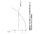
- FIG. 6 is a graph showing second-order differentiation of the refractive index distribution of the first lens in Example 1 with respect to the radial direction.
- FIG. 6 is a diagram illustrating resolution characteristics (MTF) at image heights (0.0 mm, 1.5 mm, and 3.5 mm) for the imaging optical system of Example 1.
- 6 is a diagram illustrating a configuration of an imaging optical system as Example 2.
- FIG. 10 is a graph showing second-order differentiation of the refractive index distribution of the first lens in Example 2 with respect to the radial direction.
- FIG. 6 is a diagram illustrating resolution characteristics (MTF) at image heights (0.0 mm, 1.5 mm, and 3.5 mm) for the imaging optical system of Example 2.
- FIG. 7 is a diagram illustrating a configuration of an imaging optical system as Example 3.
- FIG. 10 is a graph showing second-order differentiation of the refractive index distribution of the first lens in Example 3 with respect to the radial direction.
- FIG. 10 is a graph showing second-order differentiation of the refractive index distribution of the first lens in Example 3 with respect to the optical axis direction.
- FIG. 10 is a graph showing second-order differentiation of the refractive index distribution of the second lens in Example 3 with respect to the optical axis direction.
- FIG. 6 is a diagram illustrating resolution characteristics (MTF) at image heights (0.0 mm, 1.5 mm, and 3.5 mm) for the imaging optical system of Example 3.
- FIG. 6 is a diagram illustrating a configuration of an imaging optical system as Example 4.
- FIG. MTF resolution characteristics
- FIG. 10 is a graph showing second-order differentiation of the refractive index distribution of the first lens in Example 4 with respect to the radial direction. It is the figure which showed the resolution characteristic (MTF) in each image height (0.0 mm, 1.5 mm, 3.5 mm) about the imaging optical system of Example 4.
- FIG. 10 is a diagram illustrating a configuration of an imaging optical system as Example 5.
- FIG. 10 is a graph showing a second-order derivative with respect to the radial direction of the refractive index distribution of the first lens in Example 5.
- FIG. 10 is a diagram illustrating resolution characteristics (MTF) at image heights (0.0 mm, 1.5 mm, and 3.5 mm) for the imaging optical system of Example 5.
- Imaging Device and Imaging Optical System as Embodiment> [1-1. Configuration of imaging device] [1-2. Overview of Imaging Optical System of Embodiment] ⁇ 2. Specific Example> [2-1. Example 1] [2-2. Example 2] [2-3. Example 3] [2-4. Example 4] [2-5. Example 5] ⁇ 3. Modification>
- FIG. 1 is a block diagram illustrating an internal configuration of an imaging apparatus 1 as an embodiment. First, as a premise, it is assumed that the imaging device 1 of the present embodiment is an infrared imaging device that performs infrared imaging.
- the imaging apparatus 1 includes an optical block 2, an image sensor (imager) 3, an image signal acquisition unit 4, and an image signal processing unit 5.
- the optical block 2 comprehensively represents an imaging optical system as an embodiment described later.
- the optical block 2 condenses infrared light (infrared light) from a subject (object) indicated as incident light Li in the drawing on the imaging surface (image surface) of the image sensor 3.
- the image sensor 3 detects the infrared light collected by the optical block 2 and obtains an infrared detection signal corresponding to the infrared light from the subject.
- an infrared detection element that the image sensor 3 should have in obtaining an infrared detection signal
- a pyroelectric element can be used.
- an infrared detection element such as a thermopile type connected with a thermocouple causing the Seebeck effect or a bolometer type using a change in resistance value due to a temperature rise can be used.
- an infrared detection element it should not be limited to these, The kind will not be ask
- a shutter for periodically shielding infrared light incident on the image sensor 3 is provided.
- the pyroelectric element does not output a value corresponding to the temperature itself, but corresponds to an element that outputs a value corresponding to a temperature difference (temperature change). That is, a temperature difference is intentionally generated by creating a periodic irradiation state / shielding state of infrared light by the shutter, and thus an appropriate temperature distribution image (infrared imaged image) is obtained even for a stationary object. Is to be obtained.
- the image signal acquisition unit 4 inputs an infrared detection signal (detection signal obtained for each infrared detection element) obtained by the image sensor 3 and obtains an infrared captured image signal.
- the image signal processing unit 5 performs various types of image signal processing on the captured image signal obtained by the image signal acquisition unit 4. For example, black level correction, pixel defect compensation, aberration correction, optical shading correction, lens distortion correction, temperature adjustment, distance change amount calculation, coding, and the like are performed.
- the output from the image signal processing unit 5 is sent to a display (image display device) or the like outside the imaging device via an interface (not shown).
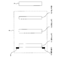
- FIG. 2 is a diagram for explaining an outline of a configuration of an imaging optical system as an embodiment provided in the optical block 2.
- FIG. 2 shows the configuration of the imaging optical system and the image sensor 3 shown in FIG.
- an aperture stop 10 In the imaging optical system of the embodiment, an aperture stop 10, a first lens 11, a second lens 12, and a sensor window 13 are arranged from the object side to the image plane side.
- the first lens 11 is a lens responsible for aberration correction, and is provided in the vicinity of the aperture stop 10.
- the first lens 10 is disposed in the vicinity of the aperture stop 10, thereby enhancing the effect of correcting the spherical aberration.
- the second lens 12 functions as a condensing lens that condenses the infrared light that has passed through the first lens 11. That is, it functions as an imaging lens that forms an infrared image on the imaging surface of the image sensor 3.
- the sensor window 13 has a flat plate shape, for example, and is provided to protect the imaging surface of the image sensor 3.
- the first lens 11 is constituted by a gradient index lens (so-called GRIN lens).
- the GRIN lens has a higher degree of design freedom than a lens having a uniform refractive index, and has a high potential as a lens element.
- the focal length f 2 of the second lens 12 is substantially the same as the focal length f of the entire imaging optical system including the second lens 12. .
- the imaging optical system is designed so as to satisfy the above condition.
- the fact that the focal length f 2 of the second lens 12 is substantially the same as the focal length f of the entire imaging optical system means that the second lens 12 has almost all the condensing function of the optical system.
- the first lens 11 side does not need to be provided with a light collecting function.
- the first lens 11 can be designed as a lens specialized for aberration correction, and as a result, the aberration correction effect can be enhanced.
- the second-order derivative along the radial direction of the refractive index distribution (hereinafter, referred to as refractive index distribution N 1 ) of the first lens 11 formed of a GRIN lens is monotonously increased. I am going to design.
- N 0 is the reference refractive index of the GRIN lens
- R is the radial position of the lens (0 on the incident surface optical axis center)
- Z is the optical axis position of the lens (incident surface optical axis center).
- Nr ij is a coefficient of the term of Rj
- nz ij is a coefficient of the term of Z j .
- the R term is up to the 6th power and the Z term is up to the 3rd power, but the same applies to higher-order terms.
- the refractive index distribution in the radial direction (r) is expressed as “N (r)”.
- the first lens 11 of the present embodiment has a second-order differential along the radial direction of such a refractive index distribution N (r). However, it is designed to increase monotonically.
- the refractive index distribution N (r) in the radial direction of the first lens 11 is expressed as “N 1 (r)”. Further, the second order differential along the radial direction of the refractive index distribution N 1 (r) of the first lens 11 is Is written.
- the refractive index distribution N 1 (r) is given so that the second-order derivative along the radial direction increases monotonously as described above, the spherical aberration correction effect by the first lens 11 can be obtained.
- FIG. 3 shows an example of a refractive index distribution pattern in the radial direction to be given for spherical aberration correction.
- the refractive index distribution N (r) as shown in FIG. 3A or FIG. 3B is given.
- the first lens 11 not only the first lens 11 but also the second lens 12 is a gradient index lens.
- the degree of freedom in designing the second lens 12 itself and the entire optical system can be improved.
- either one of the first lens 11 and the second lens 12 has a refractive index distribution in the optical axis direction.
- the degree of freedom in optical design can be further increased.
- both the first lens 11 and the second lens 12 have a refractive index distribution in the optical axis direction (Example 3).
- the optical axis direction (Z) of the refractive index distribution N 1 of the first lens 11 is aligned.
- the second-order derivative and the second-order derivative along the optical axis direction with respect to the refractive index distribution (hereinafter referred to as refractive index distribution N 2 ) of the second lens 12 have a positive / negative relationship, MTF (Modulation Transfer Function) can be improved over a wide angle of view. That is, the resolution can be improved.
- MTF Modulation Transfer Function
- N 1 (r, z) means the refractive index distribution (radial direction and optical axis direction) of the first lens 11
- N 2 (r, z) means the second lens. 12 refractive index distributions (radial direction and optical axis direction) are meant.
- T 1 and t 2 mean the center thicknesses of the first lens 11 and the second lens 12, respectively.
- the second order differential along the optical axis direction for the refractive index distribution N 1 of the first lens 11 and the second order differential along the optical axis direction for the refractive index distribution N 2 of the second lens 12 are positive / negative. Satisfying the relationship “being in a relationship” means that the aberrations are balanced on the first lens 11 side and the second lens 12 side. As a result, the effect of correcting peripheral aberrations can be enhanced, and the resolution can be improved over a wide angle of view.
- the metamaterial is an artificial structure composed of a unit cell whose one side is shorter than the wavelength used, and the unit cell has a conductor therein, and the conductor is a dielectric. It is configured to be supported.
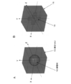
- FIG. 4 shows a structural example of the unit cell 15 constituting the metamaterial. As shown in FIG. 4A or 4B, the unit cell 15 has a conductor 16 inside thereof. The conductor 16 is supported by a dielectric, and the unit cell 15 is formed.
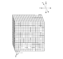
- Such unit cells 15 are laminated in the X, Y, and Z directions as shown in FIG. 5 to form a metamaterial (metamaterial lens).
- the metamaterial controls the structure in the unit cell 15 and uses either or both of the electrical resonance and the magnetic resonance with respect to the incident wavelength, so that the dielectric constant and the permeability with respect to the electromagnetic wave of the used wavelength can be obtained. Can be controlled.
- the square root of the product of dielectric constant ( ⁇ ) and magnetic permeability ( ⁇ ) is the refractive index.
- a conventional GRIN lens that does not use such a metamaterial can control the distribution of metal ions using an electromagnetic field during material dissolution or in a gel-like stage, for example, by an ion exchange method or a sol-gel method.
- it is difficult to form a complicated refractive index distribution. For this reason, it is difficult to obtain a refractive index distribution corresponding to the effect of the aspherical shape.
- the optical power of the element is determined by the refractive index difference in the radial direction and the length in the optical axis direction, but a large difference in refractive index is obtained with the conventional GRIN lens.
- the diameter is small and the shape is long on the optical axis side. That is, as a result, there is a possibility that it may be difficult to apply to an imaging optical system that requires relatively high brightness like the infrared imaging optical system exemplified in the present embodiment.
- a metamaterial lens is used as the GRIN lens.
- the square root of the product of the dielectric constant and the magnetic permeability is the refractive index. For this reason, a complicated refractive index distribution can be created relatively easily by changing the structure in the unit cell for each location.
- metamaterial lenses makes it easy to realize the existing refractive index distributions in the radial direction and the optical axis direction, and complicated refractive index distributions, which were difficult to achieve with existing GRIN lens manufacturing methods. It can be configured. That is, this makes it easy to design a high-resolution imaging optical system with high aberration correction capability.
- each lens since a large refractive index difference can be easily realized with the metamaterial lens, it is easy to make each lens (particularly the second lens 12 responsible for condensing) thinner and larger in diameter. From this point, it can be advantageous in improving the brightness of the optical system.
- the polarization characteristics can be controlled by devising the structure of the unit cell 15 constituting the metamaterial lens.
- the structure in the unit cell 15 is symmetrical with respect to the Z axis (optical axis direction) and the X axis and the Y axis on the plane perpendicular to the Z axis.
- This unit cell 15 has an isotropic refractive index. That is, the same refractive index is exhibited with respect to an incident electromagnetic wave having an arbitrary polarization direction. Normally, electromagnetic waves including all polarization directions are incident on the imaging optical system. According to the structure shown in FIG. 4A, the refractive indexes for these arbitrary polarization directions can be made equal.
- the structure can be symmetric only with respect to the two axes of the X axis and the Y axis.
- the refractive index N XY for electromagnetic waves having polarization in the XY plane is different from the refractive index N Z for electromagnetic waves having polarization in the Z-axis direction.
- the refractive index N XY is shown for electromagnetic waves incident perpendicularly to the XY plane, that is, electromagnetic waves having polarized light parallel to the XY plane, but with an angle other than perpendicular to the XY plane.
- a refractive index determined by a refractive index ellipsoid composed of XY and NZ and the direction vector of the electromagnetic wave. Will be shown. This means that even when electromagnetic waves are incident on the same location in the lens, the refractive index differs when the incident angle is different. This is especially true when designing an imaging optical system with a large angle of view. It can be.
- the metamaterial lens can be manufactured using a fine processing technique.
- the unit cell 15 can be configured by etching a conductor structure on a dielectric printed board. Or you may produce using a semiconductor process (lithography, vapor deposition, etching, etc.).
- a technique has been developed in which a conductor structure is arranged in a dielectric body on a liquid / gel and the dielectric is cured later.
- the metamaterial lens is manufactured by any one of these methods, for example.
- the unit cell 15 in this case has a substantially cubic shape, and the length m of one side thereof is about 1 ⁇ m.
- the conductor 16 is Cu (copper), and the dielectric supporting the conductor 16 is BaF 2 (barium fluoride).
- the refractive index can be changed by changing the shape of Cu.
- a cross-shaped structure is formed as the Cu structure.
- the refractive index can be adjusted according to the length b.
- the refractive index distribution of the metamaterial lens is obtained by combining unit cells 15 in which a required refractive index is set according to the shape of such a Cu plate (conductor 16) into a laminate as shown in FIG. It can be given by.
- the refractive index distribution N (r) in the radial direction can be given by stacking the unit cells 15 in the radial direction
- the refractive index distribution N (z) in the optical axis direction can be given by stacking in the optical axis direction. Is.
- a metamaterial lens having a required refractive index distribution is manufactured by such a method.
- the metamaterial lens it can be used only for the first lens 11 or both the first lens 11 and the second lens 12.
- a metamaterial lens is used for the second lens 12.
- the second lens 12 can be composed of a plurality of metamaterial lenses instead of a single metamaterial lens.
- the second lens 12 since the optical power for image formation is concentrated on the second lens 12, the second lens 12 tends to be thick.
- the second lens 12 can be made of a lens group including a plurality of metamaterial lenses, so that the manufacturing time can be shortened.
- the manufacturing time of each metamaterial lens can be shortened, and if each lens is manufactured in parallel, the second lens 12 can be manufactured.
- the manufacturing time can be significantly shortened compared with the case of constituting with one metamaterial lens.
- the thickness of each metamaterial lens shall be 0.2 mm or more from a viewpoint of ensuring intensity
- the F value is high in order to collect a larger amount of light. For example, it is desirable that the F value is 1.8 or less. In applications that require resolution, such as temperature distribution measurement, it is desirable to set the F value to 1.3 or less in order to increase the amount of collected light and improve the resolution. In each of the following embodiments, the optical system is designed in consideration of such a request for the F value.
- FIG. 8 shows the configuration of the imaging optical system as the first embodiment.
- a surface Simg in the drawing represents an imaging surface of the image sensor 3 shown in FIG. 1 (and FIG. 2) (hereinafter referred to as an imaging surface Simg).
- FIG. 8 also shows light rays of infrared light (far infrared light: center wavelength 10 ⁇ m).
- the light beam indicated by a short broken line in the drawing represents a light beam condensed at an image height of 0.0 mm
- the light beam indicated by a circular broken line represents a light beam condensed at an image height of 1.5 mm.
- a light beam indicated by a solid line represents a light beam condensed at an image height of 3.5 mm
- a light beam indicated by a long broken line represents a light beam condensed at an image height of 5.0 mm.
- metamaterial lenses are used for both the first lens 11 and the second lens 12.
- both the first lens 11 and the second lens 12 are provided with a refractive index distribution only in the radial direction, and are not provided with a refractive index distribution in the optical axis direction.
- the coefficients of the first lens 11 and the second lens 12 set in this case are shown below.
- t 1 and t 2 are the center thicknesses of the first lens 11 and the second lens 12, respectively.
- N 20 is the reference refractive index of the second lens 12.
- the distance between the object and the aperture stop 10 is 9000 mm
- the distance between the aperture stop 10 and the first lens 11 is 0 mm
- the distance between the first lens 11 and the second lens 12 is 12.27 mm
- the distance between the second lens 12 and the sensor window 13 is 9.60 mm
- the distance between the sensor window 13 and the imaging surface Simg is 0.95 mm.
- the sensor window 13 is made of Si (silicon) having a thickness of 1.0 mm, and the refractive index at a wavelength of 10 ⁇ m is 3.42.
- the focal length f of the entire optical system is 19 mm
- the diameter of the aperture stop 10 is 18.1 mm
- an F value 1.06
- a horizontal field angle of 23.8 degrees is 19
- a value obtained by second-order differentiation of the refractive index distribution N 1 of the first lens 11 with respect to the radial position R is: It is expressed.
- the second-order derivative with respect to the radial direction of the refractive index distribution N 1 in this case is monotonically increased as shown in the graph of FIG. 9 (R Monotonous increase with respect to the increase in
- focal length f 2 of the second lens 12 alone is given by the following formula when nr 22 is negative from the focal length formula of the GRIN lens.
- FIG. 10 shows resolution characteristics (MTF) at each image height (0.0 mm, 1.5 mm, 3.5 mm) for the imaging optical system of Example 1.
- MTF resolution characteristics
- the MTF value at 20 line pairs / mm is 0.3 or more at an image height of 0.0 mm corresponding to 0% and an image height of 1.5 mm corresponding to 30%.
- it is desirable that the MTF value at 10 line pairs / mm is 0.3 or more at an image height of 3.5 mm corresponding to 70%.
- the MTF value (tangential and sagittal) at 20 line pairs / mm at an image height of 0.0 mm is 0.688
- the MTF tangential at 20 line pairs / mm at an image height of 1.5 mm is achieved by the above design.
- a high resolution of 0.621, a sagittal value of 0.631, an MTF tangential value of 0.661 at 10 line pairs / mm at an image height of 3.5 mm, and a sagittal value of 0.482 are obtained.
- Example 1 by using two GRIN lenses, various aberrations such as spherical aberration, coma aberration, and astigmatism are suppressed while suppressing the number of lenses, and a high resolution image is obtained. Can be obtained.
- a GRIN lens with a metamaterial it is possible to realize a high-order refractive index distribution and a lens having a refractive index distribution in both the radial direction and the optical axis direction, with a small F value and a wide angle of view.
- an optical system can be configured in consideration of the polarization direction of incident light.
- Example 2 Also in the imaging optical system as Example 2 shown in FIG. 11, metamaterial lenses are used for both the first lens 11 and the second lens 12.
- the first lens 11 is given a refractive index distribution only in the radial direction
- the second lens 12 is given a refractive index distribution in both the radial direction and the optical axis direction.
- the coefficients of the first lens 11 and the second lens 12 in Example 2 are as follows.
- the distance between the object and the aperture stop 10 is 9000 mm, and the distance between the aperture stop 10 and the first lens 11 is 0 mm.
- the distance between the first lens 11 and the second lens 12 is 13.47 mm
- the distance between the second lens 12 and the sensor window 13 is 10.54 mm
- the distance between the sensor window 13 and the imaging surface Simg is 0.95 mm.
- the sensor window 13 is made of Si having a thickness of 1.0 mm, and the refractive index at a wavelength of 10 ⁇ m is 3.42.
- the focal length f of the entire optical system is 19 mm
- the diameter of the aperture stop 10 is 18.1 mm
- an F value 1.06 and a horizontal field angle of 23.8 degrees are realized.
- the value obtained by second-order differentiation of the refractive index distribution N 1 of the first lens 11 along the radial direction position R increases monotonously. That is, also in Example 2, since the values of nr 14 and nr 16 are positive, the second-order derivative in the radial direction of the refractive index distribution N 1 of the first lens 11 is increased by R as shown in the graph of FIG. Increase monotonously.
- FIG. 13 shows resolution characteristics (MTF) at image heights (image heights of 1.0 mm, 1.5 mm, and 3.5 mm) for the imaging optical system of Example 2.
- MTF resolution characteristics
- Example 2 by using two GRIN lenses, high-resolution images can be obtained by suppressing various aberrations such as spherical aberration, coma aberration, and astigmatism while suppressing the number of lenses. Can do.
- a metamaterial lens as a GIRN lens, it is possible to realize a high-order refractive index distribution and a lens having a refractive index distribution in both the radial direction and the optical axis direction, with a small F value and a wide angle of view.
- an optical system can be configured in consideration of the polarization direction of incident light.
- Example 3 Also in the imaging optical system as Example 3 shown in FIG. 14, metamaterial lenses are used for both the first lens 11 and the second lens 12.
- the refractive index distribution is given to both the radial direction and the optical axis direction for both the first lens 11 and the second lens 12.
- the coefficients of the first lens 11 and the second lens 12 in Example 3 are as follows.
- the distance between the object and the aperture stop 10 is 9000 mm, and the distance between the aperture stop and the first lens 11 is 0 mm.
- the distance between the first lens 11 and the second lens 12 is 13.06 mm
- the distance between the second lens 12 and the sensor window 13 is 10.38 mm
- the distance between the sensor window 13 and the imaging surface Simg is 0. 95 mm.
- the sensor window 13 is made of Si having a thickness of 1.0 mm, and the refractive index at a wavelength of 10 ⁇ m is 3.42.
- the focal length f of the entire optical system is 19 mm
- the diameter of the aperture stop is 18.1 mm
- an F value 1.06 and a horizontal field angle of 23.8 degrees are realized.
- Example 3 the value obtained by second-order differentiation of the refractive index distribution N 1 of the first lens 11 along the radial position R is monotonously increased. That is, also in this case, since the values of nr 14 and nr 16 are positive, the second-order derivative with respect to the radial direction of the refractive index distribution N 1 is monotonously increased as R increases as shown in the graph of FIG.
- Example 3 the refractive index distribution in the optical axis direction is given to both the first lens 11 and the second lens 12.
- the second derivative of the refractive index distribution N 1 of the first lens 11 with respect to the optical axis direction position Z is: It is.
- FIG. 17 shows the above [Formula 9] in a graph. As shown in FIG. 17, [Formula 9] is always negative in the range of the thickness Z of the second lens 12 from 0 to 21.59 mm. .
- Example 3 the above-described “second-order differentiation along the optical axis direction for the refractive index distribution N 1 of the first lens 11 and along the optical axis direction for the refractive index distribution N 2 of the second lens 12.
- the second-order derivative has a positive / negative relationship.
- FIG. 18 shows resolution characteristics (MTF) at image heights (0.0 mm, 1.5 mm, and 3.5 mm) for the imaging optical system of Example 3.
- MTF resolution characteristics
- Example 3 by using two GRIN lenses, it is possible to obtain a high-resolution image by suppressing various aberrations such as spherical aberration, coma and astigmatism while suppressing the number of lenses. . Also in this case, by using a metamaterial lens as a GIRN lens, it is possible to realize a high-order refractive index distribution, or a lens having a refractive index distribution in both the radial direction and the optical axis direction, with a small F-number and a field angle. And an optical system that takes into account the polarization direction of incident light.
- the imaging optical system as Example 4 also uses metamaterial lenses for both the first lens 11 and the second lens 12.
- the second lens 12 is composed of a plurality of metamaterial lenses 12a as shown in the figure.
- the second lens 12 in this case is formed by arranging each of the 20 metamaterial lenses 12a in the optical axis direction at a predetermined interval.
- the interval between the metamaterial lenses 12a is 0.2 mm.
- both the first lens 11 and the second lens 12 have a refractive index distribution in the radial direction, but only in the optical axis direction on the second lens 12 side. A refractive index distribution is given.
- the coefficients of the first lens 11 and the second lens 12 in Example 4 are as follows.
- t 2 represents the center thickness of one metamaterial lens 12a.
- the lenses 12a constituting the second lens 12 are lenses having the same design. If each lens has the same design as described above, it is possible to improve the manufacturing efficiency, resulting in cost reduction.
- each of the first lens 11 and the metamaterial lenses 12a constituting the second lens 12 is set to 1.0 mm. Thereby, each lens can be efficiently produced when the method of producing a metamaterial lens by laminating unit cell structures as described above is adopted.
- the distance between the object and the aperture stop 10 is 9000 mm, and the distance between the aperture stop 10 and the first lens 11 is 0 mm.
- the distance between the first lens 11 and the second lens 12 is 15.22 mm
- the distance between the second lens 12 and the sensor window 13 is 11.85 mm
- the distance between the sensor window 13 and the imaging surface Simg is 0.95 mm.
- the sensor window 13 is made of Si having a thickness of 1.0 mm
- the refractive index at a wavelength of 10 ⁇ m is 3.42.
- the focal length f of the entire optical system is 18.64 mm
- the diameter of the aperture stop is 17.75 mm.
- an F value 1.05 and a horizontal angle of view of 24.2 degrees are realized.
- Example 4 the value obtained by second-order differentiation of the refractive index distribution N 1 of the first lens 11 along the radial position R is graphed in FIG. 20 because the values of nr 14 and nr 16 are positive in this case as well. As shown, the increase is monotonous as R increases.
- the focal length f 2 of the second lens 12 is 18.60 mm.
- f 2 /f 0.998. Therefore, also in this case, the condition of “0.9 ⁇ f 2 /f ⁇ 1.1” is satisfied and the coma aberration and astigmatism are suppressed.
- FIG. 21 shows resolution characteristics (MTF) at image heights (image heights of 1.0 mm, 1.5 mm, and 3.5 mm) for the imaging optical system of Example 4.
- MTF resolution characteristics
- Example 4 by using the GRIN lens, various aberrations such as spherical aberration, coma aberration, and astigmatism can be suppressed, and a high-resolution image can be obtained. Also in this case, by using a metamaterial lens as a GIRN lens, it is possible to realize a high-order refractive index distribution, or a lens having a refractive index distribution in both the radial direction and the optical axis direction, with a small F-number and a field angle. And an optical system that takes into account the polarization direction of incident light.
- each metamaterial lens 12a which comprises this can also be arrange
- each lens 12a constituting the second lens 12
- reflection occurs between the lenses 12a due to a difference in refractive index with air.
- antireflection processing it is desirable to apply antireflection processing to each lens 12a.
- a technique such as forming an antireflection film on both surfaces of each metamaterial lens 12a can be employed.
- the antireflection can be realized by devising the structure of the metamaterial lens 12a instead of forming an antireflection film.
- the unit cells 15 constituting the metamaterial lens 12a are different from each other while having the same impedance as that of the adjacent substance by adjusting the ratio of the permittivity and the permeability while maintaining the product of the permittivity and the permeability. It is possible to have a refractive index. If such a property is utilized, reflection at the interface between the metamaterial lens 12a and the air can be suppressed.
- the structure which obtains the antireflection effect by the structure itself of the metamaterial lens as described above can be adopted also on the first lens 11 side, and the second lens 12 is set to 1 as in the first embodiment.
- the present invention can also be applied to the metamaterial lens in the case where the metamaterial lens is composed of one sheet.
- each of the first lens 11 and the second lens 12 is constituted by one lens, as in the first to third embodiments. Also in this case, a metamaterial lens is used for both the first lens 11 and the second lens 12.
- both the first lens 11 and the second lens 12 have a refractive index distribution only in the radial direction.
- chromatic aberration is particularly suppressed by the following design.
- the distance between the object and the aperture stop 10 is 9000 mm, and the distance between the aperture stop 10 and the first lens 11 is 0 mm.
- the distance between the first lens 10 and the second lens 12 is 14.2 mm
- the distance between the second lens 12 and the sensor window 13 is 9.65 mm
- the distance between the sensor window 13 and the imaging surface Simg is 0.95 mm.
- the sensor window 13 is made of Si having a thickness of 1.0 mm
- the refractive index at a wavelength of 10 ⁇ m is 3.42.
- the focal length f of the entire optical system is 19 mm
- the diameter of the aperture stop is 18.1 mm
- the F value 1.06
- the horizontal field angle is 23.8 degrees.
- the value obtained by second-order differentiation of the refractive index distribution N 1 of the first lens 11 at the radial position R is monotonously increased. That is, also in Example 5, since the values of nr 14 and nr 16 are positive, the second-order derivative in the radial direction of the refractive index distribution N 1 of the first lens 11 is increased by R as shown in the graph of FIG. Increase monotonously.
- FIG. 24 shows resolution characteristics (MTF) at image heights (image heights of 1.0 mm, 1.5 mm, and 3.5 mm) for the imaging optical system of Example 5.
- MTF resolution characteristics
- the fifth embodiment by using two GRIN lenses, it is possible to obtain a high-resolution image while suppressing various aberrations such as spherical aberration, coma aberration, and astigmatism while suppressing the number of lenses. Also in this case, by using a metamaterial lens as a GIRN lens, it is possible to realize a high-order refractive index distribution, or a lens having a refractive index distribution in both the radial direction and the optical axis direction, with a small F-number and a field angle. And an optical system that takes into account the polarization direction of incident light.
- the condition “0.9 ⁇ f 2 /f ⁇ 1.1” is satisfied for the focal length f 2 of the second lens 12 as described above.
- the coefficient nr 12 for determining the condensing power of one lens 11 is a value substantially equal to zero.
- chromatic aberration can be reduced by setting the coefficient nr 12 to a smaller value than 0.
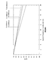
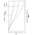
- a material with small chromatic dispersion may be used to suppress chromatic aberration, but the refractive index change characteristic as shown in FIG. 7 as in the metamaterial lens used in each example, for example.
- a metamaterial material with In FIG. 7 a structural portion having a refractive index of 1.5 for a wavelength of 10 ⁇ m has a refractive index of 1.4701 for a wavelength of 12 ⁇ m. Further, the structural portion having a refractive index of 1.7 at a wavelength of 10 ⁇ m has a refractive index of 1.6599 at a wavelength of 12 ⁇ m.
- Example 1 in which the value of nr 12 is ⁇ 0.0045619, the chromatic aberration is 0.88 mm, whereas in Example 5 in which the value of nr 12 is ⁇ 0.011, the chromatic aberration is 0.82 mm.
- the chromatic aberration is improved.
- nr 12 ⁇ 0 is sufficient to obtain the effect of suppressing chromatic aberration.
- the present technology should not be limited to the specific examples described above.
- the present technology is applied to imaging of an infrared image (wavelength of about 8 ⁇ m to 12 ⁇ m) is illustrated, but the present technology can be suitably applied to imaging of a terahertz wave.
- the terahertz wave imaging optical system may be configured, for example, such that a terahertz wave is generated by irradiating a subject with laser light and the generated terahertz wave is incident through the aperture stop 10.
- the configuration after the aperture stop 10 may be the same as that described above.
- the image sensor 3 one having sensitivity to terahertz waves is used.
- the case where the distance between the aperture stop 10 and the first lens 11 is set to 0 is exemplified.
- the first lens 11 is provided with the aperture stop 10. As close as possible to each other.
- the second lens 12 is configured by a plurality of metamaterial lenses 12a
- the lenses 12a are designed to be the same is illustrated, but lenses having different designs are used.
- the present technology can adopt the following configurations.
- a first lens provided near the aperture stop and responsible for aberration correction;
- a second lens that is disposed between the first lens and the imaging element and that collects light, and
- the imaging optical system according to (1) wherein a focal length of the second lens substantially matches an overall focal length of the imaging optical system.
- the first lens is The imaging optical system according to (2), wherein the second-order derivative along the radial direction of the refractive index distribution is designed to increase monotonously.
- the imaging optical system according to (4) wherein either the first lens or the second lens has a refractive index distribution in the optical axis direction.
- Both the first lens and the second lens have a refractive index distribution in the optical axis direction, A second-order derivative along the optical axis direction for the refractive index distribution of the first lens and a second-order derivative along the optical axis direction for the refractive index distribution of the second lens have a positive / negative relationship.
- the imaging optical system according to (4) which is designed as described above.
- (7) The imaging optical system according to any one of (4) to (6), wherein either one of the first lens and the second lens includes a metamaterial lens.
- the refractive index distribution of the first lens is (Where r represents the radial position, z represents the optical axis position, N 10 represents the reference refractive index of the first lens, nr 1j represents the coefficient of the term r j in the refractive index distribution equation, and nz 1 k represents (It is a coefficient of the term of z k in the refractive index distribution formula, j is an even number, and k is an integer.)
- the imaging optical system according to any one of (1) to (12) which forms an infrared image.
- Imaging device 1 imaging device, 2 optical block, 3 image sensor, 4 image signal acquisition unit, 5 image signal processing unit, 10 aperture stop, 11 first lens, 12 second lens, 13 sensor window, 15 unit cell, 16 conductor, Simg Imaging surface
Abstract
Description
例えば赤外線撮像光学系は、人間や動物などの対象物から発せられる熱、すなわち遠赤外線(波長8μm~12μm)を利用して、暗所での撮影や温度分布の観測等に用いられる。
また、テラヘルツ波(波長30μm~3mm:100GHz~10THz)についての撮像光学系は、例えば空港施設における手荷物検査などのいわゆる非破壊検査に用いられている。 As an imaging optical system for image detection, an imaging optical system that is used not only in a visible light region but also in a frequency region such as infrared rays and terahertz has been developed.
For example, an infrared imaging optical system is used for photographing in a dark place, observing a temperature distribution, and the like using heat emitted from an object such as a human being or an animal, that is, far infrared rays (
An imaging optical system for terahertz waves (wavelength 30 μm to 3 mm: 100 GHz to 10 THz) is used for so-called nondestructive inspection such as baggage inspection in airport facilities, for example.
しかしながら、赤外線やテラヘルツ波の波長帯では透過率等の問題から使用できるレンズ材料が少なく、加工も困難であるという問題がある。
例えば赤外線に対する透過率が比較的高い材料としてゲルマニウム等が知られているが、これら赤外線透過率の高いレンズ材料は比較的硬度が高く、加工が困難である。
加工に長時間を要するなどして、コストの削減が困難となり、特に、収差補正のため非球面形状に加工(研磨)する場合には、精密な設備を用いた長時間の作業が必要であり、高コスト化は避けられないものとなる。 In order to realize high resolution, it is desirable to suppress various optical aberrations.
However, in the wavelength band of infrared rays and terahertz waves, there are few lens materials that can be used due to problems such as transmittance, and there is a problem that processing is difficult.
For example, germanium or the like is known as a material having a relatively high transmittance with respect to infrared rays. However, these lens materials with a high infrared transmittance have a relatively high hardness and are difficult to process.
It takes a long time to process, making it difficult to reduce costs. Especially when processing (polishing) into an aspherical shape to correct aberrations, long work using precise equipment is required. High cost is inevitable.
つまり、本技術の撮像光学系は、開口絞り付近に設けられ収差補正を担う第1のレンズを備える。
また、上記第1のレンズと撮像素子との間に配置されて集光を担う第2のレンズを備える。
そして、上記第1のレンズが屈折率分布型レンズとされるものである。 In the present technology, in order to solve the above problems, the imaging optical system is configured as follows.
That is, the imaging optical system of the present technology includes a first lens that is provided near the aperture stop and performs aberration correction.
In addition, a second lens that is disposed between the first lens and the imaging device and collects light is provided.
The first lens is a gradient index lens.
すなわち、本技術の撮像装置は、上記本技術の撮像光学系を備えると共に、上記撮像光学系により結像された像を検出する像検出部と、上記像検出部による検出信号に基づいて撮像画像信号を得る画像信号取得部とを備えるものである。 In the present technology, the imaging apparatus is configured as follows.
That is, an imaging apparatus of the present technology includes the imaging optical system of the present technology, an image detection unit that detects an image formed by the imaging optical system, and a captured image based on a detection signal from the image detection unit. And an image signal acquisition unit for obtaining a signal.
なお、説明は以下の順で行う。
<1.実施の形態としての撮像装置及び撮像光学系>
[1-1.撮像装置の構成]
[1-2.実施の形態の撮像光学系の概要]
<2.具体的な実施例>
[2-1.実施例1]
[2-2.実施例2]
[2-3.実施例3]
[2-4.実施例4]
[2-5.実施例5]
<3.変形例> Hereinafter, embodiments according to the present technology will be described.
The description will be given in the following order.
<1. Imaging Device and Imaging Optical System as Embodiment>
[1-1. Configuration of imaging device]
[1-2. Overview of Imaging Optical System of Embodiment]
<2. Specific Example>
[2-1. Example 1]
[2-2. Example 2]
[2-3. Example 3]
[2-4. Example 4]
[2-5. Example 5]
<3. Modification>
[1-1.撮像装置の構成]
図1は、実施の形態としての撮像装置1の内部構成を示したブロック図である。
先ず前提として、本実施の形態の撮像装置1は、赤外線についての撮像を行う赤外線撮像装置であるとする。 <1. Imaging Device and Imaging Optical System as Embodiment>
[1-1. Configuration of imaging device]
FIG. 1 is a block diagram illustrating an internal configuration of an
First, as a premise, it is assumed that the
光学ブロック2は、後述する実施の形態としての撮像光学系を包括的に表したものである。光学ブロック2は、図中に入射光Liと示す被写体(物体)からの赤外光(赤外線)をイメージセンサ3の撮像面(像面)に集光する。 As shown in FIG. 1, the
The
赤外線検出信号を得るにあたってイメージセンサ3が備えるべき赤外線検出素子としては、例えば焦電素子を用いたものを挙げることができる。或いは、ゼーベック効果を生じさせる熱電対を接続したサーモパイル型、温度上昇による抵抗値の変化を利用したボロメータ型などの赤外線検出素子を用いることもできる。
なお、赤外線検出素子についてはこれらに限定されるべきものでなく、赤外線を検出できるものであればその種類は問わない。 The
As an infrared detection element that the
In addition, about an infrared detection element, it should not be limited to these, The kind will not be ask | required if infrared rays can be detected.
画像信号処理部5からの出力は、図示しないがインターフェース等を介して、撮像装置の外部のディスプレイ(画像表示装置)等に送られる。 The image
The output from the image
図2は、光学ブロック2内に設けられる、実施の形態としての撮像光学系の構成の概要について説明するための図である。
この図2を始めとして以下で説明する光学系の構成図(図8,11,14,19,22)においては、紙面の左側に撮像対象の物体が配置されているとする。すなわち、紙面左側が物体側、紙面右側が像面側となる。
なお、図2では撮像光学系の構成と共に、先の図1に示したイメージセンサ3も併せて示している。 [1-2. Overview of Imaging Optical System of Embodiment]
FIG. 2 is a diagram for explaining an outline of a configuration of an imaging optical system as an embodiment provided in the
In the configuration diagram of the optical system (FIGS. 8, 11, 14, 19, and 22) described below starting with FIG. 2, it is assumed that an object to be imaged is arranged on the left side of the drawing. That is, the left side of the drawing is the object side, and the right side of the drawing is the image side.
2 also shows the configuration of the imaging optical system and the
第1レンズ11は、収差補正を担うレンズであり、開口絞り10付近に設けられる。このように第1レンズ10が開口絞り10付近に配置されることで、球面収差の補正効果が高まる。 As shown in the drawing, in the imaging optical system of the embodiment, an
The
GRINレンズは、屈折率が一様なレンズに比して設計上の自由度が高く、レンズ用素子として高い潜在力を持つものである。
このようなGRINレンズを第1レンズ11に用いることで、収差補正にあたり従来のように高コストな加工を要することがなくなり、この点でコスト削減が図られる。 Here, in the imaging optical system of the present embodiment, at least the
The GRIN lens has a higher degree of design freedom than a lens having a uniform refractive index, and has a high potential as a lens element.
By using such a GRIN lens for the
具体的には、例えば

Specifically, for example

ただし[式2]において、N0はGRINレンズの基準屈折率であり、Rはレンズの半径方向位置(入射面光軸中心を0)、Zはレンズの光軸方向位置(入射面光軸中心を0)を意味する。また、nrijはRjの項の係数、nzijはZjの項の係数である。
なおここでは簡単のため、Rの項は6乗まで、Zの項は3乗までを記載しているが、さらに高次項を用いても同様である。 Here, the refractive index distribution N of the GRIN lens is
In [Expression 2], N 0 is the reference refractive index of the GRIN lens, R is the radial position of the lens (0 on the incident surface optical axis center), and Z is the optical axis position of the lens (incident surface optical axis center). Means 0). Nr ij is a coefficient of the term of Rj, and nz ij is a coefficient of the term of Z j .
For simplicity, the R term is up to the 6th power and the Z term is up to the 3rd power, but the same applies to higher-order terms.
本実施の形態の第1レンズ11は、このような屈折率分布N(r)の半径方向に沿った二階微分

The
また、この第1レンズ11の屈折率分布N1(r)の半径方向に沿った二階微分は

Further, the second order differential along the radial direction of the refractive index distribution N 1 (r) of the
球面収差補正効果を得るにあたっては、これら図3A又は図3Bに示されるような屈折率分布N(r)を与えることになる。 Here, FIG. 3 shows an example of a refractive index distribution pattern in the radial direction to be given for spherical aberration correction.
In obtaining the spherical aberration correction effect, the refractive index distribution N (r) as shown in FIG. 3A or FIG. 3B is given.
このことより、屈折率分布N1(r)の半径方向に沿った二階微分が単調増加となる第1レンズ11によれば、球面収差補正効果が得られるものである。 For any of the refractive index distributions N (r) shown in FIG. 3A and FIG. 3B, it is understood that the result is monotonously increased when second-order differentiation is performed along the radial direction.
Thus, according to the
このことで、第2レンズ12自体、及び光学系全体の設計自由度の向上を図ることができる。 Here, in the present embodiment, not only the
Thus, the degree of freedom in designing the
光軸方向にも屈折率分布を持たせることで、光学設計の設計自由度をさらに増すことができる。 In the present embodiment, either one of the
By providing a refractive index distribution also in the optical axis direction, the degree of freedom in optical design can be further increased.
このように第1レンズ11と第2レンズ12の双方に光軸方向にも屈折率分布を持たせる場合には、第1レンズ11の屈折率分布N1についての光軸方向(Z)に沿った二階微分と、第2レンズ12の屈折率分布(以下、屈折率分布N2と表記)についての光軸方向に沿った二階微分とが、正/負の関係となるようにすることで、広い画角においてMTF(Modulation Transfer Function)を改善できる。すなわち、分解能を向上できる。 Here, in an example described later, a configuration is proposed in which both the
As described above, when both the

ここで、メタマテリアルは、一辺の長さが使用波長よりも短い単位セルで構成された人工構造物であり、上記単位セルが、その内部に導電体を有し、該導電体が誘電体で支持されて構成されるものである。 In the present embodiment, a so-called metamaterial lens can be used as the GRIN lens.
Here, the metamaterial is an artificial structure composed of a unit cell whose one side is shorter than the wavelength used, and the unit cell has a conductor therein, and the conductor is a dielectric. It is configured to be supported.
図4A又は図4Bに示されるように、単位セル15は、その内部に導電体16を有している。この導電体16が誘電体により支持されて、単位セル15が形成されるものである。 FIG. 4 shows a structural example of the
As shown in FIG. 4A or 4B, the
周知のように誘電率(ε)と透磁率(μ)の積の平方根が屈折率となるものである。 Here, the metamaterial controls the structure in the
As is well known, the square root of the product of dielectric constant (ε) and magnetic permeability (μ) is the refractive index.
つまりその結果として、本実施の形態で例示している赤外線撮像光学系のように比較的明るさを必要とする撮像光学系への適用が、困難となる虞がある。 When the refractive index distribution is given in the radial direction, the optical power of the element is determined by the refractive index difference in the radial direction and the length in the optical axis direction, but a large difference in refractive index is obtained with the conventional GRIN lens. As a result, there is a possibility that sufficient optical power cannot be obtained unless the diameter is small and the shape is long on the optical axis side.
That is, as a result, there is a possibility that it may be difficult to apply to an imaging optical system that requires relatively high brightness like the infrared imaging optical system exemplified in the present embodiment.
メタマテリアルレンズでは、上述のように誘電率と透磁率の積の平方根が屈折率となる。このため、単位セル内の構造を場所ごとに変えることにより、複雑な屈折率分布を比較的容易に作り出すことができる。 In view of this point, in each example described later, a metamaterial lens is used as the GRIN lens.
In the metamaterial lens, as described above, the square root of the product of the dielectric constant and the magnetic permeability is the refractive index. For this reason, a complicated refractive index distribution can be created relatively easily by changing the structure in the unit cell for each location.
つまりこのことで、収差補正能力の高い高分解能な撮像光学系の設計が容易となるものである。 For this reason, using metamaterial lenses makes it easy to realize the existing refractive index distributions in the radial direction and the optical axis direction, and complicated refractive index distributions, which were difficult to achieve with existing GRIN lens manufacturing methods. It can be configured.
That is, this makes it easy to design a high-resolution imaging optical system with high aberration correction capability.
例えば先の図4Aに示したように、単位セル15内の構造がZ軸(光軸方向)、及びZ軸に垂直な面上にあるX軸及びY軸の3軸に対して対称な構造を有していれば、この単位セル15は、等方的な屈折率を持つ。つまり、任意の偏光方向を持つ入射電磁波に対して、同じ屈折率を示すことになる。
通常、撮像光学系にはあらゆる偏光方向を含んだ電磁波が入射する。図4Aに示す構造によれば、それら任意の偏光方向に対する屈折率を等しくできる。 Here, when a metamaterial lens is used, the polarization characteristics can be controlled by devising the structure of the
For example, as shown in FIG. 4A, the structure in the
Normally, electromagnetic waves including all polarization directions are incident on the imaging optical system. According to the structure shown in FIG. 4A, the refractive indexes for these arbitrary polarization directions can be made equal.
このとき、X-Y平面に垂直に入射する電磁波、つまりX-Y平面に平行な偏光をもつ電磁波に対しては屈折率NX-Yを示すが、X-Y平面に垂直以外の角度を持って入射した電磁波や、X-Y平面に垂直に入射してもその後屈折した電磁波に対しては、NX-YとNZからなる屈折率楕円体と、その電磁波の方向ベクトルとで決定される屈折率を示すことになる。
これは、レンズ内の同じ場所に入射する電磁波でも、入射角が異なると屈折率が異なることを意味しており、特に画角の大きな撮像光学系の設計を行う場合には、一つの自由度とすることができる。 Alternatively, as shown in FIG. 4B, the structure can be symmetric only with respect to the two axes of the X axis and the Y axis. In this case, the refractive index N XY for electromagnetic waves having polarization in the XY plane is different from the refractive index N Z for electromagnetic waves having polarization in the Z-axis direction.
At this time, the refractive index N XY is shown for electromagnetic waves incident perpendicularly to the XY plane, that is, electromagnetic waves having polarized light parallel to the XY plane, but with an angle other than perpendicular to the XY plane. For an incident electromagnetic wave or an electromagnetic wave that is refracted after being incident perpendicular to the XY plane, a refractive index determined by a refractive index ellipsoid composed of XY and NZ and the direction vector of the electromagnetic wave. Will be shown.
This means that even when electromagnetic waves are incident on the same location in the lens, the refractive index differs when the incident angle is different. This is especially true when designing an imaging optical system with a large angle of view. It can be.
例えば、誘電体製のプリント基板上に導電体構造をエッチングすることで単位セル15を構成することができる。或いは、半導体プロセス(リソグラフィ、蒸着、エッチング等)を用いて作製しても良い。
また、液体・ゲル上の誘電体内に導電体構成を配置して後に、誘電体を硬化させる手法も開発されている。
本実施の形態において、メタマテリアルレンズの作製は、例えばこれら何れかの手法により行う。 The metamaterial lens can be manufactured using a fine processing technique.
For example, the
In addition, a technique has been developed in which a conductor structure is arranged in a dielectric body on a liquid / gel and the dielectric is cured later.
In the present embodiment, the metamaterial lens is manufactured by any one of these methods, for example.
図6において、先ず前提として、この場合における単位セル15は略立方体形状とされ、その一辺の長さmがおよそ1μmとされているとする。
この場合、導電体16はCu(銅)であり、該導電体16を支持する誘電体はBaF2(フッ化バリウム)とされる。 With reference to FIG. 6, a specific method for providing a refractive index distribution in the metamaterial lens will be described.
In FIG. 6, first of all, it is assumed that the
In this case, the
例えばこの図の例では、Cuの構造体として十字型の構造体を構成するものとしている。
十字型のCuが有する4つの手のそれぞれの幅aは一定とする(例えばa=180nm)。このとき、十字の手の長さbを図6A,図6Bに示すように変化させると、該長さbに応じて屈折率を調整できる When the Cu structure is supported in the
For example, in the example of this figure, a cross-shaped structure is formed as the Cu structure.
The width a of each of the four hands of the cross-shaped Cu is constant (for example, a = 180 nm). At this time, if the length b of the cross hand is changed as shown in FIGS. 6A and 6B, the refractive index can be adjusted according to the length b.
具体的にこの図7では、手の長さbをb=300nm~800nmの範囲で100nmごとに変化させた際における波長(μm)に対する屈折率変化特性を示している。
この図7からも、手の長さbによって屈折率を調整できることが分かる。 FIG. 7 shows the measurement result of the refractive index when the length b of the hand is changed.
Specifically, FIG. 7 shows the refractive index change characteristics with respect to the wavelength (μm) when the hand length b is changed every 100 nm in the range of b = 300 nm to 800 nm.
FIG. 7 also shows that the refractive index can be adjusted by the hand length b.
後述する各実施例においては、このような手法により所要の屈折率分布を持つメタマテリアルレンズを作製するものとした。 The refractive index distribution of the metamaterial lens is obtained by combining
In each example to be described later, a metamaterial lens having a required refractive index distribution is manufactured by such a method.
これまでの説明からも理解されるように、本実施の形態では、結像のための光学パワーを第2レンズ12に集中させていることから、第2レンズ12は厚くなる傾向となる。導電体構造や誘電体を積層してメタマテリアルレンズを作製する場合には、レンズ厚さが厚くなると、その分製造時間も長くなってしまう。
そこで、特に第2レンズ12については、複数枚のメタマテリアルレンズから成るレンズ群で構成することで、製造時間の短縮化を図ることができる。すなわち、メタマテリアルレンズ1枚あたりの厚さを薄くできるので、個々のメタマテリアルレンズの製造時間を短縮化することができ、各レンズの製造を並行して行うものとすれば、第2レンズ12の製造時間は1枚のメタマテリアルレンズで構成する場合よりも大幅に短縮化できるものである。
なお、このように複数のメタマテリアルレンズから成るレンズ群とする場合、個々のメタマテリアルレンズの厚さは、強度確保の観点より0.2mm以上とすることが望ましい。 Here, in the present embodiment, as the metamaterial lens, it can be used only for the
As understood from the above description, in the present embodiment, since the optical power for image formation is concentrated on the
Therefore, in particular, the
In addition, when it is set as the lens group which consists of a some metamaterial lens in this way, it is desirable that the thickness of each metamaterial lens shall be 0.2 mm or more from a viewpoint of ensuring intensity | strength.
後述する具体的な実施例においては、この点を考慮して光学系の設計を行っている。 By the way, in recent years, devices using far-infrared rays have been used as temperature sensors and human sensors, but these have a low resolution, and the shape of the object to be imaged like a thermoviewer or night vision system. Devices that have an optical system that forms an image up to are limited. In the future, widening the angle of view of the optical system is required in order to expand the widespread use of devices. Specifically, it is desirable that the angle of view exceeds at least 25 °.
In a specific embodiment to be described later, the optical system is designed in consideration of this point.
また、温度分布測定等の解像度の必要な用途においては、集光量を上げ分解能の向上を図るべく、F値=1.3以下とすることが望ましい。
以下の各実施例においては、このようなF値に係る要請も考慮して光学系の設計を行っている。 Further, since far-infrared light and terahertz waves have low energy, the image sensor used for visible light cannot be used, and the sensitivity of the
In applications that require resolution, such as temperature distribution measurement, it is desirable to set the F value to 1.3 or less in order to increase the amount of collected light and improve the resolution.
In each of the following embodiments, the optical system is designed in consideration of such a request for the F value.
[2-1.実施例1]
図8は、実施例1としての撮像光学系の構成を示している。
なお図8において、図中の面Simgは、図1(及び図2)に示したイメージセンサ3の撮像面を表す(以下、撮像面Simgと表記)。
また図8では赤外光(遠赤外光:中心波長10μm)の光線も併せて示している。
図中の短破線で示す光線は像高0.0mmに集光する光線を表し、丸破線で示す光線は像高1.5mmに集光する光線を表している。また実線で示す光線は像高3.5mmに、長破線で示す光線は像高5.0mmにそれぞれ集光する光線を表す。 <2. Specific Example>
[2-1. Example 1]
FIG. 8 shows the configuration of the imaging optical system as the first embodiment.
In FIG. 8, a surface Simg in the drawing represents an imaging surface of the
Further, FIG. 8 also shows light rays of infrared light (far infrared light:
The light beam indicated by a short broken line in the drawing represents a light beam condensed at an image height of 0.0 mm, and the light beam indicated by a circular broken line represents a light beam condensed at an image height of 1.5 mm. A light beam indicated by a solid line represents a light beam condensed at an image height of 3.5 mm, and a light beam indicated by a long broken line represents a light beam condensed at an image height of 5.0 mm.
そして本実施例では、これら第1レンズ11、第2レンズ12の双方とも、半径方向にのみ屈折率分布を与えるものとし、光軸方向への屈折率分布付与は行っていない。
具体的に、この場合に設定した第1レンズ11、第2レンズ12の各係数を以下に示す。
第1レンズ11
t1:0.51mm
N10=1.5
nr12=-0.0045619
nr14=2.6341×10⁻⁵
nr16=3.9083×10⁻⁸
nz11=0
nz12=0
nz13=0
第2レンズ12
t2:20.98mm
N20=1.7
nr22=-0.0014226
nr24=1.5207×10⁻⁷
nr26=-2.4759×10⁻¹⁰
nz11=0
nz12=0
nz13=0
ただし、t1、t2はそれぞれ第1レンズ11、第2レンズ12の中心厚さである。
また、N20は第2レンズ12の基準屈折率である。 In this embodiment, metamaterial lenses are used for both the
In this embodiment, both the
Specifically, the coefficients of the
t 1 : 0.51 mm
N 10 = 1.5
nr 12 = −0.0045619
nr 14 = 2.6341 × 10 −5
nr 16 = 3.9083 × 10 −8
nz 11 = 0
nz 12 = 0
nz 13 = 0
t 2 : 20.98 mm
N 20 = 1.7
nr 22 = −0.0014226
nr 24 = 1.5207 × 10 −7
nr 26 = −2.4759 × 10 −10
nz 11 = 0
nz 12 = 0
nz 13 = 0
Here, t 1 and t 2 are the center thicknesses of the
N 20 is the reference refractive index of the
センサ窓13は、厚み1.0mmのSi(シリコン)製であり、波長10μmにおける屈折率は3.42である。
光学系全体の焦点距離fは19mmであり、開口絞り10の直径は18.1mmで、F値=1.06、水平画角23.8度を実現している。 As the configuration of the imaging optical system, the distance between the object and the
The
The focal length f of the entire optical system is 19 mm, the diameter of the

実施例1では、nr14とnr16の値が正であるため、この場合における屈折率分布N1の半径方向に対する二階微分は、図9にそのグラフを示すように、単調増加となる(Rの増加に対し単調増加)。 Here, a value obtained by second-order differentiation of the refractive index distribution N 1 of the
In Example 1, since the values of nr 14 and nr 16 are positive, the second-order derivative with respect to the radial direction of the refractive index distribution N 1 in this case is monotonically increased as shown in the graph of FIG. 9 (R Monotonous increase with respect to the increase in

従って、f2/f=1.0であり、前述した「0.9≦f2/f≦1.1」による条件を満たす。つまりこのことから、収差(コマ収差及びアス収差)を抑制する構成となっていることが分かる。 According to [Expression 7] and the coefficient nr 22 = −0.0014226 set for the
Therefore, a f 2 /f=1.0, satisfying by "0.9 ≦ f 2 /f≦1.1" earlier. That is, from this, it can be seen that the structure is configured to suppress aberrations (coma and astigmatism).
なおこの図10を始めとして以降で示すMTF図(図13,18,21,24)の共通事項として、図中の短波線は像高0.0mmの特性、丸波線は像高1.5mmの特性、実線は像高3.5mmの特性を表す。また、図中「T」の表記はタンジェンシャル値を意味し、「S」の表記はサジタル値を意味する。 FIG. 10 shows resolution characteristics (MTF) at each image height (0.0 mm, 1.5 mm, 3.5 mm) for the imaging optical system of Example 1.
In addition, as a matter common to the MTF diagrams (FIGS. 13, 18, 21, and 24) shown in FIG. 10 and thereafter, the short wave line in the figure has a characteristic of an image height of 0.0 mm, and the round wave line has an image height of 1.5 mm. The characteristics and the solid line represent the characteristics of an image height of 3.5 mm. In the figure, the notation “T” means a tangential value, and the notation “S” means a sagittal value.
また、GRINレンズをメタマテリアルによって作製することにより、高次数の屈折率分布や、半径方向と光軸方向にともに屈折率分布をもつレンズが実現可能となり、F値が小さく、画角の広い、さらに入射光の偏光方向を考慮した光学系を構成できる。 According to Example 1 described above, by using two GRIN lenses, various aberrations such as spherical aberration, coma aberration, and astigmatism are suppressed while suppressing the number of lenses, and a high resolution image is obtained. Can be obtained.
In addition, by producing a GRIN lens with a metamaterial, it is possible to realize a high-order refractive index distribution and a lens having a refractive index distribution in both the radial direction and the optical axis direction, with a small F value and a wide angle of view. Furthermore, an optical system can be configured in consideration of the polarization direction of incident light.
図11は、実施例2としての撮像光学系の構成を示している。
なお、図11においても各像高(0.0mm、1.5mm、3.5mm、5.0mm)に集光する赤外光の光線を併せて示している。この場合も像高0.0mm=短破線、像高1.5mm=丸破線、像高3.5mm=実線、像高5.0mm=長破線となる。 [2-2. Example 2]
FIG. 11 shows a configuration of an imaging optical system as the second embodiment.
Note that FIG. 11 also shows infrared rays condensed at each image height (0.0 mm, 1.5 mm, 3.5 mm, and 5.0 mm). Also in this case, the image height 0.0 mm = short broken line, the image height 1.5 mm = round broken line, the image height 3.5 mm = solid line, and the image height 5.0 mm = long broken line.
実施例2では、第1レンズ11が半径方向に対してのみ屈折率分布が付与され、第2レンズ12には、半径方向と光軸方向の双方に対して屈折率分布を与えるものとしている。
実施例2における第1レンズ11、第2レンズ12の係数は以下の通りである。
第1レンズ11
t1:1.45mm
N10=1.5
nr12=-0.0026979
nr14=8.3000×10⁻⁶
nr16=1.3708×10⁻⁸
nz11=0
nz12=0
nz13=0
第2レンズ12
t2:22.1mm
N20=1.7
nr22=-0.0012917
nr24=6.0592×10⁻⁸
nr26=-1.0504×10⁻¹⁰
nz11=0.18715
nz12=-0.010492
nz13=0.00016204 Also in the imaging optical system as Example 2 shown in FIG. 11, metamaterial lenses are used for both the
In Example 2, the
The coefficients of the
t 1 : 1.45 mm
N 10 = 1.5
nr 12 = −0.00269979
nr 14 = 8.3000 × 10 −6
nr 16 = 1.3708 × 10 −8
nz 11 = 0
nz 12 = 0
nz 13 = 0
t 2 : 22.1 mm
N 20 = 1.7
nr 22 = −0.0012917
nr 24 = 6.0592 × 10 −8
nr 26 = −1.0504 × 10 −10
nz 11 = 0.18715
nz 12 = −0.010492
nz 13 = 0.00016204
実施例2においてもセンサ窓13は厚み1.0mmのSi製であり、波長10μmにおける屈折率は3.42である。
この場合も光学系全体の焦点距離fは19mm、開口絞り10の直径は18.1mmであり、F値=1.06、水平画角23.8度を実現している。 Also in Example 2, the distance between the object and the
Also in Example 2, the
Also in this case, the focal length f of the entire optical system is 19 mm, the diameter of the
すなわち、実施例2においても、nr14とnr16の値が正のため、図12にグラフ化して示すように、第1レンズ11の屈折率分布N1の半径方向に対する二階微分はRの増加に対して単調増加となる。 Also in the optical system of Example 2, the value obtained by second-order differentiation of the refractive index distribution N 1 of the
That is, also in Example 2, since the values of nr 14 and nr 16 are positive, the second-order derivative in the radial direction of the refractive index distribution N 1 of the
よって、この場合も「0.9≦f2/f≦1.1」の条件を満たし、コマ収差及びアス収差を抑制する構成となっている。 Further, in Example 2, the focal length f 2 of the
Therefore, also in this case, the condition of “0.9 ≦ f 2 /f≦1.1” is satisfied and the coma aberration and astigmatism are suppressed.
実施例2の場合、像高0.0mmにおける20line pairs/mmでのMTF値(タンジェンシャル及びサジタル)が0.687、像高1.5mmにおける20line pairs/mmでのMTFのタンジェンシャル値0.664、サジタル値0.715、像高3.5mmにおける10line pairs/mmでのMTFのタンジェンシャル値0.824、サジタル値0.781と、高い分解能が得られる。 FIG. 13 shows resolution characteristics (MTF) at image heights (image heights of 1.0 mm, 1.5 mm, and 3.5 mm) for the imaging optical system of Example 2.
In the case of Example 2, the MTF value (tangential and sagittal) at 20 line pairs / mm at an image height of 0.0 mm was 0.687, and the tangential value of MTF at 20 line pairs / mm at an image height of 1.5 mm was 0.00. A high resolution of 664, a sagittal value of 0.715, an MTF tangential value of 0.824 at 10 line pairs / mm at an image height of 3.5 mm, and a sagittal value of 0.781 is obtained.
図14は、実施例3としての撮像光学系の構成を示している。
なお、図13においても各像高(0.0mm、1.5mm、3.5mm、5.0mm)に集光する赤外光の光線を併せて示している。この場合も像高0.0mm=短破線、像高1.5mm=丸破線、像高3.5mm=実線、像高5.0mm=長破線となる。 [2-3. Example 3]
FIG. 14 shows the configuration of an imaging optical system as Example 3.
Note that FIG. 13 also shows infrared rays condensed at each image height (0.0 mm, 1.5 mm, 3.5 mm, 5.0 mm). Also in this case, the image height 0.0 mm = short broken line, the image height 1.5 mm = round broken line, the image height 3.5 mm = solid line, and the image height 5.0 mm = long broken line.
実施例3では、第1レンズ11、第2レンズ12の双方について、半径方向と光軸方向の双方に対する屈折率分布の付与を行うものとしている。
実施例3における第1レンズ11、第2レンズ12の係数は以下の通りである。
第1レンズ11
t1:0.32mm
N10=1.5
nr12=-0.0084099
nr14=4.5915×10⁻⁵
nr16=2.3249×10⁻⁸
nz11=-11.279
nz12=54.660
nz13=-53.038
第2レンズ12
t2:21.59mm
N20=1.7
nr22=-0.0013365
nr24=1.0580×10⁻⁷
nr26=-2.0880×10⁻¹⁰
nz11=0.16587
nz12=-0.011007
nz13=0.00013715 Also in the imaging optical system as Example 3 shown in FIG. 14, metamaterial lenses are used for both the
In Example 3, the refractive index distribution is given to both the radial direction and the optical axis direction for both the
The coefficients of the
t 1 : 0.32 mm
N 10 = 1.5
nr 12 = −0.0084099
nr 14 = 4.5915 × 10 −5
nr 16 = 2.3249 × 10 −8
nz 11 = -11.279
nz 12 = 54.660
nz 13 = -53.038
t 2 : 21.59 mm
N 20 = 1.7
nr 22 = −0.0013365
nr 24 = 1.0580 × 10 −7
nr 26 = −2.0880 × 10 −10
nz 11 = 0.16587
nz 12 = −0.011007
nz 13 = 0.00013715
この場合もセンサ窓13は厚み1.0mmのSi製であり、波長10μmにおける屈折率は3.42である。
本実施例においても、光学系全体の焦点距離fは19mm、開口絞りの直径は18.1mmであり、F値=1.06、水平画角23.8度を実現している。 Also in Example 3, the distance between the object and the
Also in this case, the
Also in this embodiment, the focal length f of the entire optical system is 19 mm, the diameter of the aperture stop is 18.1 mm, and an F value = 1.06 and a horizontal field angle of 23.8 degrees are realized.
すなわち、この場合もnr14とnr16の値が正のため、図15にグラフ化して示すように、屈折率分布N1の半径方向に対する二階微分はRの増加に対して単調増加となる。 Also in Example 3, the value obtained by second-order differentiation of the refractive index distribution N 1 of the
That is, also in this case, since the values of nr 14 and nr 16 are positive, the second-order derivative with respect to the radial direction of the refractive index distribution N 1 is monotonously increased as R increases as shown in the graph of FIG.
よって、この場合も「0.9≦f2/f≦1.1」を満たし、コマ収差とアス収差を抑制する構成となっている。 In Example 3, the focal length f 2 of the
Therefore, also in this case, “0.9 ≦ f 2 /f≦1.1” is satisfied, and coma and astigmatism are suppressed.
第1レンズ11の屈折率分布N1の光軸方向位置Zに対する二階微分は、

図16は、上記[式8]をグラフ化して示しているが、この図16に示されるように、[式8]は第1レンズ11の厚さZ=0~0.32mmの範囲で常に正となる。 Here, in Example 3, the refractive index distribution in the optical axis direction is given to both the
The second derivative of the refractive index distribution N 1 of the
FIG. 16 shows the above [Formula 8] in a graph. As shown in FIG. 16, [Formula 8] is always in the range of the thickness Z = 0 to 0.32 mm of the

図17に上記[式9]をグラフ化して示すが、この図17にあるように[式9]は第2レンズ12の厚さZ=0~21.59mmの範囲で常に負となっている。 On the other hand, the second derivative with respect to the optical axis direction position Z of the refractive index distribution N 2 of the
FIG. 17 shows the above [Formula 9] in a graph. As shown in FIG. 17, [Formula 9] is always negative in the range of the thickness Z of the
すなわち、実施例3は、前述した「第1レンズ11の屈折率分布N1についての光軸方向に沿った二階微分と、第2レンズ12の屈折率分布N2についての光軸方向に沿った二階微分とが正/負の関係となる」との条件を満たすものである。 Therefore, the above-mentioned [Expression 8] In z = t 1/2 is positive, the [equation 9] In z = t 2/2 is negative.
That is, in Example 3, the above-described “second-order differentiation along the optical axis direction for the refractive index distribution N 1 of the
実施例3では、像高0.0mmにおける20line pairs/mmでのMTF値(タンジェンシャル及びサジタル)が0.718、像高1.5mmにおける20line pairs/mmでのMTFのタンジェンシャル値0.655、サジタル値0.658、像高3.5mmにおける10line pairs/mmでのMTFのタンジェンシャル値0.692、サジタル値0.707と、高い分解能が得られる。 FIG. 18 shows resolution characteristics (MTF) at image heights (0.0 mm, 1.5 mm, and 3.5 mm) for the imaging optical system of Example 3.
In Example 3, the MTF value (tangential and sagittal) at 20 line pairs / mm at an image height of 0.0 mm is 0.718, and the tangential value of MTF at 20 line pairs / mm at an image height of 1.5 mm is 0.655. A high resolution is obtained with a sagittal value of 0.658, an MTF tangential value of 0.692 at 10 line pairs / mm at an image height of 3.5 mm, and a sagittal value of 0.707.
図19は、実施例4としての撮像光学系の構成を示している。
なお、図19においても各像高(0.0mm、1.5mm、3.5mm、5.0mm)に集光する赤外光の光線を併せて示している。この場合も像高0.0mm=短破線、像高1.5mm=丸破線、像高3.5mm=実線、像高5.0mm=長破線となる。 [2-4. Example 4]
FIG. 19 shows a configuration of an imaging optical system as Example 4.
Note that FIG. 19 also shows infrared rays condensed at each image height (0.0 mm, 1.5 mm, 3.5 mm, 5.0 mm). Also in this case, the image height 0.0 mm = short broken line, the image height 1.5 mm = round broken line, the image height 3.5 mm = solid line, and the image height 5.0 mm = long broken line.
実施例4は、図示するように第2レンズ12を複数のメタマテリアルレンズ12aで構成するようにしたものである。
具体的に、この場合の第2レンズ12は、20枚のメタマテリアルレンズ12aの個々を所定間隔を空けて光軸方向に配列させて成る。本例において、各メタマテリアルレンズ12aの間隔は0.2mmとした。 The imaging optical system as Example 4 also uses metamaterial lenses for both the
In the fourth embodiment, the
Specifically, the
第1レンズ11
t1:1.0mm
N10=1.5
nr12=-0.0030892
nr14=1.4311×10⁻⁵
nr16=1.7893×10⁻⁸
nz11=0.0
nz12=0.0
nz13=0.0
第2レンズ12を構成する個々のメタマテリアルレンズ12a
t2:1.0mm
N20=1.7
nr22=-0.0014303404
nr24=6.8750×10⁻⁸
nr26=-9.9276×10⁻¹¹
nz11=21.915
nz12=-13.609
nz13=4.3708
確認のため述べておくと、この場合、上記t2は1枚のメタマテリアルレンズ12aの中心厚さを表すものとなる。 The coefficients of the
t 1 : 1.0 mm
N 10 = 1.5
nr 12 = −0.0030892
nr 14 = 1.4311 × 10 −5
nr 16 = 1.7893 × 10 −8
nz 11 = 0.0
nz 12 = 0.0
nz 13 = 0.0
t 2 : 1.0 mm
N 20 = 1.7
nr 22 = −0.0014303404
nr 24 = 6.8750 × 10 −8
nr 26 = −9.9276 × 10 −11
nz 11 = 21.915
nz 12 = -13.609
nz 13 = 4.3708
For confirmation, in this case, t 2 represents the center thickness of one
このように各レンズを同じ設計とすれば、製造効率の向上を図ることができ、結果としてコストの削減に繋がる。 Here, as can be understood from the above set values, in this example, the
If each lens has the same design as described above, it is possible to improve the manufacturing efficiency, resulting in cost reduction.
この場合もセンサ窓13は厚み1.0mmのSi製であり、波長10μmにおける屈折率は3.42である。
またこの場合、光学系全体の焦点距離fは18.64mmであり、開口絞りの直径は17.75mmである。
実施例4では、F値=1.05、水平画角24.2度を実現している。 Also in Example 4, the distance between the object and the
Also in this case, the
In this case, the focal length f of the entire optical system is 18.64 mm, and the diameter of the aperture stop is 17.75 mm.
In the fourth embodiment, an F value = 1.05 and a horizontal angle of view of 24.2 degrees are realized.
よって、この場合も「0.9≦f2/f≦1.1」の条件を満たし、コマ収差とアス収差を抑制する構成となっている。 In this case, the focal length f 2 of the
Therefore, also in this case, the condition of “0.9 ≦ f 2 /f≦1.1” is satisfied and the coma aberration and astigmatism are suppressed.
実施例4の場合、像高0.0mmにおける20line pairs/mmでのMTF値(タンジェンシャル及びサジタル)が0.727、像高1.5mmにおける20line pairs/mmでのMTFのタンジェンシャル値0.695、サジタル値0.719、像高3.5mmにおける10line pairs/mmでのMTFのタンジェンシャル値0.811、サジタル値0.852と、高い分解能が得られる。 FIG. 21 shows resolution characteristics (MTF) at image heights (image heights of 1.0 mm, 1.5 mm, and 3.5 mm) for the imaging optical system of Example 4.
In the case of Example 4, the MTF value (tangential and sagittal) at 20 line pairs / mm at an image height of 0.0 mm was 0.727, and the tangential value of MTF at 20 line pairs / mm at an image height of 1.5 mm was 0.00. 695, sagittal value 0.719, MTF tangential value 0.811 at 10 line pairs / mm at an image height of 3.5 mm, and sagittal value 0.852, high resolution is obtained.
この際、例えば各レンズ12aの平面度のばらつき等に起因して、各レンズ12aを隙間無く密着させて配置することが困難な場合がある。各レンズ12aの間に不要な隙間が生じた場合、光干渉が生じる虞があり、この点を考慮すれば、各レンズ12aは所定の間隔を空けて配置することが望ましいと言える。 By the way, about the
At this time, for example, due to variations in the flatness of the
例えば各メタマテリアルレンズ12aの両面に反射防止膜を成膜するなどの手法を採ることができる。 Here, when the
For example, a technique such as forming an antireflection film on both surfaces of each
ここで、メタマテリアルレンズ12aを構成する単位セル15は、その誘電率と透磁率の積を保ちつつ、誘電率と透磁率の比を調整することで、隣接する物質と同じインピーダンスを持ちながら異なる屈折率を持たせることが可能である。このような性質を利用すれば、メタマテリアルレンズ12aと空気との境界面での反射を抑制することができる。
具体的に、単位セル15内の構造を、誘電率εと透磁率μが等しくなるように構成すると、屈折率n=(εμ)1/2を調整しながら、インピーダンスZ=(μ/ε)1/2=1とすることができ、空気との境界面におけるフレネル反射を抑えることができるものである。 Alternatively, the antireflection can be realized by devising the structure of the
Here, the
Specifically, when the structure in the
図22は、実施例5としての撮像光学系の構成を示している。
なお、図22においても各像高(0.0mm、1.5mm、3.5mm、5.0mm)に集光する赤外光の光線を併せて示している。この場合も像高0.0mm=短破線、像高1.5mm=丸破線、像高3.5mm=実線、像高5.0mm=長破線となる。 [2-5. Example 5]
FIG. 22 shows a configuration of an imaging optical system as Example 5.
Note that FIG. 22 also shows infrared rays condensed at each image height (0.0 mm, 1.5 mm, 3.5 mm, 5.0 mm). Also in this case, the image height 0.0 mm = short broken line, the image height 1.5 mm = round broken line, the image height 3.5 mm = solid line, and the image height 5.0 mm = long broken line.
この場合も第1レンズ11、第2レンズ12の双方にメタマテリアルレンズを用いるものとしている。
また実施例5では、先の実施例1と同様に、第1レンズ11、第2レンズ12の双方に半径方向にのみ屈折率分布を持たせるものとしている。 As shown in FIG. 22, in the imaging optical system according to the fifth embodiment, each of the
Also in this case, a metamaterial lens is used for both the
In the fifth embodiment, as in the first embodiment, both the
実施例5で設定した第1レンズ11、第2レンズ12の係数を以下に示す。
第1レンズ11
t1:0.4mm
N10=1.5
nr12=-0.011
nr14=3.2962×10⁻⁵
nr16=4.3911×10⁻⁸
nz11=0
nz12=0
nz13=0
第2レンズ12
t2:16.07mm
N20=1.7
nr22=-0.0018027
nr24=2.5702×10⁻⁷
nr26=-3.7334×10⁻¹⁰
nz11=0
nz12=0
nz13=0 In the fifth embodiment, chromatic aberration is particularly suppressed by the following design.
The coefficients of the
t 1 : 0.4 mm
N 10 = 1.5
nr 12 = −0.011
nr 14 = 3.2962 × 10 −5
nr 16 = 4.3911 × 10 −8
nz 11 = 0
nz 12 = 0
nz 13 = 0
t 2 : 16.07 mm
N 20 = 1.7
nr 22 = −0.0018027
nr 24 = 2.5702 × 10 −7
nr 26 = −3.7334 × 10 −10
nz 11 = 0
nz 12 = 0
nz 13 = 0
この場合、第1レンズ10-第2レンズ12間の距離は14.2mm、第2レンズ12-センサ窓13間の距離は9.65mm、センサ窓13-撮像面Simg間の距離は0.95mmとしている。
この場合もセンサ窓13は厚み1.0mmのSi製であり、波長10μmにおける屈折率は3.42である。
本例の場合、光学系全体の焦点距離fは19mmであり、開口絞りの直径は18.1mmで、F値=1.06、水平画角23.8度を実現している。 Also in Example 5, the distance between the object and the
In this case, the distance between the
Also in this case, the
In the case of this example, the focal length f of the entire optical system is 19 mm, the diameter of the aperture stop is 18.1 mm, the F value = 1.06, and the horizontal field angle is 23.8 degrees.
実施例5の場合、像高0.0mmにおける20line pairs/mmでのMTF値(タンジェンシャル及びサジタル)が0.676、像高1.5mmにおける20line pairs/mmでのMTFのタンジェンシャル値0.583、サジタル値0.667、像高3.5mmにおける10line pairs/mmでのMTFのタンジェンシャル値0.588、サジタル値0.475と、高い分解能が得られている。 FIG. 24 shows resolution characteristics (MTF) at image heights (image heights of 1.0 mm, 1.5 mm, and 3.5 mm) for the imaging optical system of Example 5.
In the case of Example 5, the MTF value (tangential and sagittal) at 20 line pairs / mm at an image height of 0.0 mm is 0.676, and the tangential value of MTF at 20 line pairs / mm at an image height of 1.5 mm is 0.00. 583, sagittal value 0.667, MTF tangential value 0.588 at 10 line pairs / mm at an image height of 3.5 mm, and sagittal value 0.475, high resolution is obtained.
また、この場合もGIRNレンズとしてメタマテリアルレンズを用いることで、高次数の屈折率分布や、半径方向と光軸方向にともに屈折率分布をもつレンズが実現可能となり、F値が小さく、画角の広い、さらに入射光の偏光方向を考慮した光学系を構成できる。 Also in the fifth embodiment, by using two GRIN lenses, it is possible to obtain a high-resolution image while suppressing various aberrations such as spherical aberration, coma aberration, and astigmatism while suppressing the number of lenses.
Also in this case, by using a metamaterial lens as a GIRN lens, it is possible to realize a high-order refractive index distribution, or a lens having a refractive index distribution in both the radial direction and the optical axis direction, with a small F-number and a field angle. And an optical system that takes into account the polarization direction of incident light.
図7において、このメタマテリアル材料では、波長10μmに対して屈折率1.5を持つ構造部分は、波長12μmに対しては1.4701の屈折率を持つ。また波長10μmで屈折率1.7となる構造部分は、波長12μmで1.6599の屈折率を持つ。
このとき、nr12の値が-0.0045619である実施例1では色収差が0.88mmであるのに対し、nr12の値が-0.011である実施例5では、色収差が0.82mmとなり、色収差が改善されるものとなる。 It is obvious that a material with small chromatic dispersion may be used to suppress chromatic aberration, but the refractive index change characteristic as shown in FIG. 7 as in the metamaterial lens used in each example, for example. Consider the case of using a metamaterial material with
In FIG. 7, in this metamaterial, a structural portion having a refractive index of 1.5 for a wavelength of 10 μm has a refractive index of 1.4701 for a wavelength of 12 μm. Further, the structural portion having a refractive index of 1.7 at a wavelength of 10 μm has a refractive index of 1.6599 at a wavelength of 12 μm.
At this time, in Example 1 in which the value of nr 12 is −0.0045619, the chromatic aberration is 0.88 mm, whereas in Example 5 in which the value of nr 12 is −0.011, the chromatic aberration is 0.82 mm. Thus, the chromatic aberration is improved.
なお、nr12の値のみについてみれば、色収差の抑制効果を得るにあたっては、少なくとも「nr12<0」とすればよいものである。 Therefore, it can be seen that a design in which chromatic aberration is further suppressed is possible by using a material or metamaterial material with smaller chromatic dispersion and making nr 12 smaller than 0.
In view of only the value of nr 12 , at least “nr 12 <0” is sufficient to obtain the effect of suppressing chromatic aberration.
以上、本技術の撮像光学系及び撮像装置に係る実施形態について説明したが、本技術としてはこれまでで説明した具体例に限定されるべきものではない。
例えば、各実施例においては、本技術が赤外線画像(波長8μm~12μm程度)の撮像に適用される場合を例示したが、本技術は、テラヘルツ波の撮像にも好適に適用できる。
テラヘルツ波の撮像光学系としては、例えば被写体に対しレーザ光を照射してテラヘルツ波を発生させ、該発生させたテラヘルツ波を開口絞り10を介して入射するように構成すればよい。開口絞り10以降の構成は、これまでで説明したものと同様でよい。またイメージセンサ3については、テラヘルツ波に対する感度を有するものを用いる。 <3. Modification>
Although the embodiments of the imaging optical system and the imaging apparatus according to the present technology have been described above, the present technology should not be limited to the specific examples described above.
For example, in each of the embodiments, the case where the present technology is applied to imaging of an infrared image (wavelength of about 8 μm to 12 μm) is illustrated, but the present technology can be suitably applied to imaging of a terahertz wave.
The terahertz wave imaging optical system may be configured, for example, such that a terahertz wave is generated by irradiating a subject with laser light and the generated terahertz wave is incident through the
(1)
開口絞り付近に設けられ収差補正を担う第1のレンズと、
上記第1のレンズと撮像素子との間に配置されて集光を担う第2のレンズと
を備えると共に、
上記第1のレンズが屈折率分布型レンズとされる
撮像光学系。
(2)
上記第2レンズの焦点距離が当該撮像光学系の全体焦点距離と略一致している上記(1)に記載の撮像光学系。
(3)
上記第1のレンズは、
その屈折率分布についての半径方向に沿った二階微分が単調増加となるように設計されている
上記(2)に記載の撮像光学系。
(4)
上記第2のレンズが屈折率分布型レンズとされる上記(3)に記載の撮像光学系。
(5)
上記第1のレンズ又は上記第2のレンズの何れかが光軸方向への屈折率分布をもつ上記(4)に記載の撮像光学系。
(6)
上記第1のレンズと上記第2のレンズの双方が、光軸方向への屈折率分布をもち、
上記第1のレンズの屈折率分布についての光軸方向に沿った二階微分と、上記第2のレンズの屈折率分布についての光軸方向に沿った二階微分とが、正/負の関係となるように設計されている
上記(4)に記載の撮像光学系。
(7)
上記第1のレンズ又は上記第2のレンズのうちの何れか一方がメタマテリアルレンズを有して構成される
上記(4)乃至(6)何れかに記載の撮像光学系。
(8)
上記メタマテリアルレンズは、その内部の任意の一点において、光軸に垂直な任意の偏光方向に対する屈折率が等しくなるように構成されている
上記(7)に記載の撮像光学系。
(9)
上記メタマテリアルレンズは、その内部の任意の一点において、任意の偏光方向に対する屈折率が等しくなるように構成されている
上記(7)に記載の撮像光学系。
(10)
上記第2のレンズが複数枚のメタマテリアルレンズで構成されている上記(7)乃至(9)何れかに記載の撮像光学系。
(11)
上記第2のレンズを構成する各上記メタマテリアルレンズが所定間隔を空けて配列されている
上記(10)に記載の撮像光学系。
(12)
上記第1のレンズの屈折率分布が

で表されるとき、

(13)
赤外線の像を結像する上記(1)乃至(12)何れかに記載の撮像光学系。
(14)
テラヘルツ波の像を結像する上記(1)乃至(12)何れかに記載の撮像光学系。 In addition, the present technology can adopt the following configurations.
(1)
A first lens provided near the aperture stop and responsible for aberration correction;
A second lens that is disposed between the first lens and the imaging element and that collects light, and
An imaging optical system in which the first lens is a gradient index lens.
(2)
The imaging optical system according to (1), wherein a focal length of the second lens substantially matches an overall focal length of the imaging optical system.
(3)
The first lens is
The imaging optical system according to (2), wherein the second-order derivative along the radial direction of the refractive index distribution is designed to increase monotonously.
(4)
The imaging optical system according to (3), wherein the second lens is a gradient index lens.
(5)
The imaging optical system according to (4), wherein either the first lens or the second lens has a refractive index distribution in the optical axis direction.
(6)
Both the first lens and the second lens have a refractive index distribution in the optical axis direction,
A second-order derivative along the optical axis direction for the refractive index distribution of the first lens and a second-order derivative along the optical axis direction for the refractive index distribution of the second lens have a positive / negative relationship. The imaging optical system according to (4), which is designed as described above.
(7)
The imaging optical system according to any one of (4) to (6), wherein either one of the first lens and the second lens includes a metamaterial lens.
(8)
The imaging optical system according to (7), wherein the metamaterial lens is configured such that a refractive index with respect to an arbitrary polarization direction perpendicular to the optical axis is equal at an arbitrary point inside the metamaterial lens.
(9)
The imaging optical system according to (7), wherein the metamaterial lens is configured so that a refractive index with respect to an arbitrary polarization direction is equal at an arbitrary point inside the metamaterial lens.
(10)
The imaging optical system according to any one of (7) to (9), wherein the second lens includes a plurality of metamaterial lenses.
(11)
The imaging optical system according to (10), wherein each of the metamaterial lenses constituting the second lens is arranged at a predetermined interval.
(12)
The refractive index distribution of the first lens is
When represented by
(13)
The imaging optical system according to any one of (1) to (12), which forms an infrared image.
(14)
The imaging optical system according to any one of (1) to (12), which forms an image of a terahertz wave.
Claims (15)
- 開口絞り付近に設けられ収差補正を担う第1のレンズと、
上記第1のレンズと撮像素子との間に配置されて集光を担う第2のレンズと
を備えると共に、
上記第1のレンズが屈折率分布型レンズとされる
撮像光学系。 A first lens provided near the aperture stop and responsible for aberration correction;
A second lens that is disposed between the first lens and the imaging element and that collects light, and
An imaging optical system in which the first lens is a gradient index lens. - 上記第2レンズの焦点距離が当該撮像光学系の全体焦点距離と略一致している請求項1に記載の撮像光学系。 The imaging optical system according to claim 1, wherein a focal length of the second lens substantially matches an overall focal length of the imaging optical system.
- 上記第1のレンズは、
その屈折率分布についての半径方向に沿った二階微分が単調増加となるように設計されている
請求項2に記載の撮像光学系。 The first lens is
The imaging optical system according to claim 2, wherein the second-order derivative along the radial direction with respect to the refractive index distribution is designed to increase monotonously. - 上記第2のレンズが屈折率分布型レンズとされる請求項3に記載の撮像光学系。 The imaging optical system according to claim 3, wherein the second lens is a gradient index lens.
- 上記第1のレンズ又は上記第2のレンズの何れかが光軸方向への屈折率分布をもつ請求項4に記載の撮像光学系。 5. The imaging optical system according to claim 4, wherein either the first lens or the second lens has a refractive index distribution in the optical axis direction.
- 上記第1のレンズと上記第2のレンズの双方が、光軸方向への屈折率分布をもち、
上記第1のレンズの屈折率分布についての光軸方向に沿った二階微分と、上記第2のレンズの屈折率分布についての光軸方向に沿った二階微分とが、正/負の関係となるように設計されている
請求項4に記載の撮像光学系。 Both the first lens and the second lens have a refractive index distribution in the optical axis direction,
A second-order derivative along the optical axis direction for the refractive index distribution of the first lens and a second-order derivative along the optical axis direction for the refractive index distribution of the second lens have a positive / negative relationship. The imaging optical system according to claim 4, which is designed as follows. - 上記第1のレンズ又は上記第2のレンズのうちの何れか一方がメタマテリアルレンズとされる
請求項4に記載の撮像光学系。 The imaging optical system according to claim 4, wherein any one of the first lens and the second lens is a metamaterial lens. - 上記メタマテリアルレンズは、その内部の任意の一点において、光軸に垂直な任意の偏光方向に対する屈折率が等しくなるように構成されている
請求項7に記載の撮像光学系。 The imaging optical system according to claim 7, wherein the metamaterial lens is configured so that a refractive index with respect to an arbitrary polarization direction perpendicular to the optical axis is equal at an arbitrary point inside the metamaterial lens. - 上記メタマテリアルレンズは、その内部の任意の一点において、任意の偏光方向に対する屈折率が等しくなるように構成されている
請求項7に記載の撮像光学系。 The imaging optical system according to claim 7, wherein the metamaterial lens is configured such that a refractive index with respect to an arbitrary polarization direction is equal at an arbitrary point inside the metamaterial lens. - 上記第2のレンズが複数枚のメタマテリアルレンズで構成されている請求項7に記載の撮像光学系。 The imaging optical system according to claim 7, wherein the second lens includes a plurality of metamaterial lenses.
- 上記第2のレンズを構成する各上記メタマテリアルレンズが所定間隔を空けて配列されている
請求項10に記載の撮像光学系。 The imaging optical system according to claim 10, wherein each of the metamaterial lenses constituting the second lens is arranged at a predetermined interval. - 上記第1のレンズの屈折率分布が

で表されるとき、

When represented by
- 赤外線の像を結像する請求項1に記載の撮像光学系。 The imaging optical system according to claim 1, which forms an infrared image.
- テラヘルツ波の像を結像する請求項1に記載の撮像光学系。 The imaging optical system according to claim 1, which forms a terahertz wave image.
- 開口絞り付近に設けられ収差補正を担う第1のレンズと、上記第1のレンズと撮像素子との間に配置されて集光を担う第2のレンズとを備えると共に、上記第1のレンズが屈折率分布型レンズとされる撮像光学系と、
上記撮像光学系により結像された像を検出する像検出部と、
上記像検出部による検出信号に基づいて撮像画像信号を得る画像信号取得部と
を備える撮像装置。 A first lens provided near the aperture stop for performing aberration correction; and a second lens disposed between the first lens and the imaging device for collecting light. The first lens includes: An imaging optical system that is a gradient index lens;
An image detector for detecting an image formed by the imaging optical system;
An imaging apparatus comprising: an image signal acquisition unit that obtains a captured image signal based on a detection signal from the image detection unit.
Priority Applications (4)
| Application Number | Priority Date | Filing Date | Title |
|---|---|---|---|
| JP2014515477A JP6164212B2 (en) | 2012-05-16 | 2013-04-12 | Imaging optical system, imaging device |
| US14/399,045 US10215970B2 (en) | 2012-05-16 | 2013-04-12 | Image-pickup optical system and image pickup apparatus to correct aberration |
| CN201380024311.5A CN104272162B (en) | 2012-05-16 | 2013-04-12 | imaging optical system, imaging device |
| US16/249,380 US11169364B2 (en) | 2012-05-16 | 2019-01-16 | Image-pickup optical system and image pickup apparatus |
Applications Claiming Priority (2)
| Application Number | Priority Date | Filing Date | Title |
|---|---|---|---|
| JP2012-112423 | 2012-05-16 | ||
| JP2012112423 | 2012-05-16 |
Related Child Applications (2)
| Application Number | Title | Priority Date | Filing Date |
|---|---|---|---|
| US14/399,045 A-371-Of-International US10215970B2 (en) | 2012-05-16 | 2013-04-12 | Image-pickup optical system and image pickup apparatus to correct aberration |
| US16/249,380 Continuation US11169364B2 (en) | 2012-05-16 | 2019-01-16 | Image-pickup optical system and image pickup apparatus |
Publications (1)
| Publication Number | Publication Date |
|---|---|
| WO2013171969A1 true WO2013171969A1 (en) | 2013-11-21 |
Family
ID=49583402
Family Applications (1)
| Application Number | Title | Priority Date | Filing Date |
|---|---|---|---|
| PCT/JP2013/002515 WO2013171969A1 (en) | 2012-05-16 | 2013-04-12 | Imaging optical system, imaging device |
Country Status (4)
| Country | Link |
|---|---|
| US (2) | US10215970B2 (en) |
| JP (1) | JP6164212B2 (en) |
| CN (1) | CN104272162B (en) |
| WO (1) | WO2013171969A1 (en) |
Cited By (1)
| Publication number | Priority date | Publication date | Assignee | Title |
|---|---|---|---|---|
| WO2015156231A1 (en) * | 2014-04-07 | 2015-10-15 | 浜松ホトニクス株式会社 | Metamaterial optical member, light detection device, laser excitation light source, and measuring device |
Families Citing this family (11)
| Publication number | Priority date | Publication date | Assignee | Title |
|---|---|---|---|---|
| US9482796B2 (en) * | 2014-02-04 | 2016-11-01 | California Institute Of Technology | Controllable planar optical focusing system |
| US11469265B2 (en) | 2015-07-29 | 2022-10-11 | Samsung Electronics Co., Ltd. | Imaging apparatus and image sensor including the same |
| US11089286B2 (en) | 2015-07-29 | 2021-08-10 | Samsung Electronics Co., Ltd. | Image sensor |
| US10403668B2 (en) | 2015-07-29 | 2019-09-03 | Samsung Electronics Co., Ltd. | Imaging apparatus and image sensor including the same |
| US10790325B2 (en) | 2015-07-29 | 2020-09-29 | Samsung Electronics Co., Ltd. | Imaging apparatus and image sensor including the same |
| US10274599B2 (en) * | 2016-06-01 | 2019-04-30 | Toyota Motor Engineering & Manufacturing North America, Inc. | LIDAR systems with expanded fields of view on a planar substrate |
| CN107092075B (en) * | 2017-03-14 | 2019-06-07 | 中国工程物理研究院激光聚变研究中心 | A kind of big view field imaging object lens of the high relative aperture of terahertz wave band |
| DE102018114005A1 (en) * | 2018-06-12 | 2019-12-12 | Carl Zeiss Jena Gmbh | Material testing of optical specimens |
| KR102094192B1 (en) * | 2018-09-07 | 2020-04-23 | 고려대학교 산학협력단 | Anti-reflection coating film and manufacturing method thereof |
| TWI745745B (en) * | 2019-09-10 | 2021-11-11 | 光芒光學股份有限公司 | Imaging lens and a manufacturing method of a light- shielding element |
| EP3968059A1 (en) * | 2020-09-11 | 2022-03-16 | Samsung Electronics Co., Ltd. | Meta lens assembly and electronic device including the same |
Citations (8)
| Publication number | Priority date | Publication date | Assignee | Title |
|---|---|---|---|---|
| JPH08286133A (en) * | 1995-04-14 | 1996-11-01 | Asahi Optical Co Ltd | Scanning optical system and its spherical aberration correcting method |
| WO2000052511A1 (en) * | 1999-03-03 | 2000-09-08 | Mitsubishi Denki Kabushiki Kaisha | Infrared optical system for infrared camera |
| JP2004258310A (en) * | 2003-02-26 | 2004-09-16 | Nikon Corp | Wide angle lens equipped with gradient index lens |
| JP2008507733A (en) | 2004-07-23 | 2008-03-13 | ザ リージェンツ オブ ザ ユニバーシティ オブ カリフォルニア | Metamaterial |
| JP2010526318A (en) | 2007-05-04 | 2010-07-29 | トヨタ モーター エンジニアリング アンド マニュファクチャリング ノース アメリカ,インコーポレイティド | Active radar system |
| JP2010527565A (en) | 2007-05-15 | 2010-08-12 | トヨタ モーター エンジニアリング アンド マニュファクチャリング ノース アメリカ,インコーポレイティド | Gradient index lens for microwave radiation |
| JP2011082324A (en) | 2009-10-07 | 2011-04-21 | Canon Inc | Solid-state image sensor |
| JP2011158665A (en) * | 2010-01-29 | 2011-08-18 | Sony Corp | Method for manufacturing meta-material member and meta-material member |
Family Cites Families (10)
| Publication number | Priority date | Publication date | Assignee | Title |
|---|---|---|---|---|
| JP3585297B2 (en) * | 1995-09-12 | 2004-11-04 | オリンパス株式会社 | Objective lens |
| JPH09318989A (en) * | 1996-05-27 | 1997-12-12 | Sony Corp | Camera-shake correcting optical system |
| US6130787A (en) * | 1997-10-02 | 2000-10-10 | Olympus Optical Co., Ltd. | Optical system and optical module |
| CN1316893A (en) | 1998-07-10 | 2001-10-10 | 金伯利-克拉克环球有限公司 | Disposable underpants including skewed absorbent core |
| US6927927B2 (en) * | 2001-11-27 | 2005-08-09 | Minolta Co., Ltd. | Taking lens system |
| JP4260061B2 (en) * | 2003-05-23 | 2009-04-30 | 三洋電機株式会社 | Gradient index lens and composite optical element using the same |
| US7864394B1 (en) * | 2005-08-31 | 2011-01-04 | The United States Of America As Represented By The Secretary Of The Navy | Dynamically variable metamaterial lens and method |
| CN101414047B (en) * | 2008-04-28 | 2010-06-09 | 深圳市大族激光科技股份有限公司 | Optical lens |
| US20110204891A1 (en) * | 2009-06-25 | 2011-08-25 | Lockheed Martin Corporation | Direct magnetic imaging apparatus and method |
| EP2287639A3 (en) * | 2009-08-17 | 2012-05-30 | Sony Corporation | Lens array imaging optics for a line sensor module |
-
2013
- 2013-04-12 CN CN201380024311.5A patent/CN104272162B/en active Active
- 2013-04-12 JP JP2014515477A patent/JP6164212B2/en not_active Expired - Fee Related
- 2013-04-12 WO PCT/JP2013/002515 patent/WO2013171969A1/en active Application Filing
- 2013-04-12 US US14/399,045 patent/US10215970B2/en active Active
-
2019
- 2019-01-16 US US16/249,380 patent/US11169364B2/en active Active
Patent Citations (8)
| Publication number | Priority date | Publication date | Assignee | Title |
|---|---|---|---|---|
| JPH08286133A (en) * | 1995-04-14 | 1996-11-01 | Asahi Optical Co Ltd | Scanning optical system and its spherical aberration correcting method |
| WO2000052511A1 (en) * | 1999-03-03 | 2000-09-08 | Mitsubishi Denki Kabushiki Kaisha | Infrared optical system for infrared camera |
| JP2004258310A (en) * | 2003-02-26 | 2004-09-16 | Nikon Corp | Wide angle lens equipped with gradient index lens |
| JP2008507733A (en) | 2004-07-23 | 2008-03-13 | ザ リージェンツ オブ ザ ユニバーシティ オブ カリフォルニア | Metamaterial |
| JP2010526318A (en) | 2007-05-04 | 2010-07-29 | トヨタ モーター エンジニアリング アンド マニュファクチャリング ノース アメリカ,インコーポレイティド | Active radar system |
| JP2010527565A (en) | 2007-05-15 | 2010-08-12 | トヨタ モーター エンジニアリング アンド マニュファクチャリング ノース アメリカ,インコーポレイティド | Gradient index lens for microwave radiation |
| JP2011082324A (en) | 2009-10-07 | 2011-04-21 | Canon Inc | Solid-state image sensor |
| JP2011158665A (en) * | 2010-01-29 | 2011-08-18 | Sony Corp | Method for manufacturing meta-material member and meta-material member |
Cited By (4)
| Publication number | Priority date | Publication date | Assignee | Title |
|---|---|---|---|---|
| WO2015156231A1 (en) * | 2014-04-07 | 2015-10-15 | 浜松ホトニクス株式会社 | Metamaterial optical member, light detection device, laser excitation light source, and measuring device |
| JP2015200745A (en) * | 2014-04-07 | 2015-11-12 | 浜松ホトニクス株式会社 | Metamaterial optical member, optical detector, laser exciting light source, and measuring device |
| GB2538930A (en) * | 2014-04-07 | 2016-11-30 | Hamamatsu Photonics Kk | Metamaterial optical member, light detection device, laser excitation light source, and measuring device |
| US10161857B2 (en) | 2014-04-07 | 2018-12-25 | Hamamatsu Photonics K.K. | Metamaterial optical member, light detection device, laser excitation light source, and measuring device |
Also Published As
| Publication number | Publication date |
|---|---|
| US11169364B2 (en) | 2021-11-09 |
| US20190219799A1 (en) | 2019-07-18 |
| JPWO2013171969A1 (en) | 2016-01-12 |
| JP6164212B2 (en) | 2017-07-19 |
| CN104272162B (en) | 2016-09-21 |
| CN104272162A (en) | 2015-01-07 |
| US20150130973A1 (en) | 2015-05-14 |
| US10215970B2 (en) | 2019-02-26 |
Similar Documents
| Publication | Publication Date | Title |
|---|---|---|
| JP6164212B2 (en) | Imaging optical system, imaging device | |
| JP5617642B2 (en) | Infrared optical system, infrared imaging device | |
| JP5803532B2 (en) | Infrared optical system, infrared imaging device | |
| US8681428B1 (en) | High refractive index, polarization insensitive nano-rod based plasmonic metamaterials for lenses | |
| US10782513B2 (en) | Total internal reflection aperture stop imaging | |
| Banerji et al. | Imaging over an unlimited bandwidth with a single diffractive surface | |
| KR101215826B1 (en) | Photographic lens optical system | |
| JP2011253006A (en) | Infrared imaging lens and imaging apparatus | |
| JP2011128538A (en) | Infrared imaging lens and imaging apparatus | |
| CN107991763A (en) | A kind of high definition long-focus LONG WAVE INFRARED camera lens | |
| WO2013179592A1 (en) | Infrared optical assembly and infrared image capture device | |
| KR101118910B1 (en) | Photographic lens optical system | |
| CN106291895A (en) | A kind of wide field staring double-colored prior-warning device of type infrared and ultraviolet | |
| KR101008704B1 (en) | Objective lens system for thermal image device | |
| KR20190055862A (en) | Short Wave Infrared Camera Optical System for The Long Range Image Monitoring | |
| Yang et al. | Free-form lens design for wide-angle imaging with an equidistance projection scheme | |
| KR20210033773A (en) | Apparatus for evaluating performance of lens module and relay lens system applicable thereto | |
| Lin et al. | Wide field-of-view, large-area long-wave infrared silicon metalenses | |
| Wirth-Singh et al. | Large field-of-view thermal imaging via all-silicon meta-optics | |
| KR20100122346A (en) | Photographic lens optical system | |
| CN220305553U (en) | Optical system for infrared band and thermal infrared imager comprising same | |
| CN115113375B (en) | Camera module and camera device | |
| XUAN et al. | Current status of space remote sensing equipments research base in CIOMP | |
| CN114089513B (en) | Infrared ultra-wide temperature athermal optical system at-70 ℃ to +100 DEG C | |
| US20230051264A1 (en) | Superhydrophobic surface in thermal infrared imaging device |
Legal Events
| Date | Code | Title | Description |
|---|---|---|---|
| 121 | Ep: the epo has been informed by wipo that ep was designated in this application |
Ref document number: 13790208 Country of ref document: EP Kind code of ref document: A1 |
|
| ENP | Entry into the national phase |
Ref document number: 2014515477 Country of ref document: JP Kind code of ref document: A |
|
| WWE | Wipo information: entry into national phase |
Ref document number: 2013790208 Country of ref document: EP |
|
| WWE | Wipo information: entry into national phase |
Ref document number: 14399045 Country of ref document: US |
|
| NENP | Non-entry into the national phase |
Ref country code: DE |