WO2013168744A1 - Procédé et dispositif de détection de sources lumineuses d'un véhicule - Google Patents
Procédé et dispositif de détection de sources lumineuses d'un véhicule Download PDFInfo
- Publication number
- WO2013168744A1 WO2013168744A1 PCT/JP2013/062950 JP2013062950W WO2013168744A1 WO 2013168744 A1 WO2013168744 A1 WO 2013168744A1 JP 2013062950 W JP2013062950 W JP 2013062950W WO 2013168744 A1 WO2013168744 A1 WO 2013168744A1
- Authority
- WO
- WIPO (PCT)
- Prior art keywords
- light source
- vehicle
- accuracy
- color
- captured image
- Prior art date
Links
- 238000000034 method Methods 0.000 title claims description 29
- 238000001514 detection method Methods 0.000 claims description 19
- 238000000605 extraction Methods 0.000 claims description 17
- 239000000284 extract Substances 0.000 claims description 7
- 230000000007 visual effect Effects 0.000 claims description 4
- 230000003287 optical effect Effects 0.000 description 5
- 238000003384 imaging method Methods 0.000 description 4
- 230000006870 function Effects 0.000 description 2
- 230000006399 behavior Effects 0.000 description 1
- 238000010586 diagram Methods 0.000 description 1
- 238000002372 labelling Methods 0.000 description 1
- 230000004044 response Effects 0.000 description 1
Images
Classifications
-
- G—PHYSICS
- G06—COMPUTING; CALCULATING OR COUNTING
- G06V—IMAGE OR VIDEO RECOGNITION OR UNDERSTANDING
- G06V20/00—Scenes; Scene-specific elements
- G06V20/50—Context or environment of the image
- G06V20/56—Context or environment of the image exterior to a vehicle by using sensors mounted on the vehicle
- G06V20/58—Recognition of moving objects or obstacles, e.g. vehicles or pedestrians; Recognition of traffic objects, e.g. traffic signs, traffic lights or roads
- G06V20/584—Recognition of moving objects or obstacles, e.g. vehicles or pedestrians; Recognition of traffic objects, e.g. traffic signs, traffic lights or roads of vehicle lights or traffic lights
-
- B—PERFORMING OPERATIONS; TRANSPORTING
- B60—VEHICLES IN GENERAL
- B60Q—ARRANGEMENT OF SIGNALLING OR LIGHTING DEVICES, THE MOUNTING OR SUPPORTING THEREOF OR CIRCUITS THEREFOR, FOR VEHICLES IN GENERAL
- B60Q1/00—Arrangement of optical signalling or lighting devices, the mounting or supporting thereof or circuits therefor
- B60Q1/02—Arrangement of optical signalling or lighting devices, the mounting or supporting thereof or circuits therefor the devices being primarily intended to illuminate the way ahead or to illuminate other areas of way or environments
- B60Q1/04—Arrangement of optical signalling or lighting devices, the mounting or supporting thereof or circuits therefor the devices being primarily intended to illuminate the way ahead or to illuminate other areas of way or environments the devices being headlights
- B60Q1/14—Arrangement of optical signalling or lighting devices, the mounting or supporting thereof or circuits therefor the devices being primarily intended to illuminate the way ahead or to illuminate other areas of way or environments the devices being headlights having dimming means
- B60Q1/1415—Dimming circuits
- B60Q1/1423—Automatic dimming circuits, i.e. switching between high beam and low beam due to change of ambient light or light level in road traffic
-
- G—PHYSICS
- G01—MEASURING; TESTING
- G01J—MEASUREMENT OF INTENSITY, VELOCITY, SPECTRAL CONTENT, POLARISATION, PHASE OR PULSE CHARACTERISTICS OF INFRARED, VISIBLE OR ULTRAVIOLET LIGHT; COLORIMETRY; RADIATION PYROMETRY
- G01J3/00—Spectrometry; Spectrophotometry; Monochromators; Measuring colours
- G01J3/46—Measurement of colour; Colour measuring devices, e.g. colorimeters
-
- B—PERFORMING OPERATIONS; TRANSPORTING
- B60—VEHICLES IN GENERAL
- B60Q—ARRANGEMENT OF SIGNALLING OR LIGHTING DEVICES, THE MOUNTING OR SUPPORTING THEREOF OR CIRCUITS THEREFOR, FOR VEHICLES IN GENERAL
- B60Q2300/00—Indexing codes for automatically adjustable headlamps or automatically dimmable headlamps
- B60Q2300/40—Indexing codes relating to other road users or special conditions
- B60Q2300/41—Indexing codes relating to other road users or special conditions preceding vehicle
-
- G—PHYSICS
- G06—COMPUTING; CALCULATING OR COUNTING
- G06T—IMAGE DATA PROCESSING OR GENERATION, IN GENERAL
- G06T2207/00—Indexing scheme for image analysis or image enhancement
- G06T2207/10—Image acquisition modality
- G06T2207/10024—Color image
-
- G—PHYSICS
- G06—COMPUTING; CALCULATING OR COUNTING
- G06T—IMAGE DATA PROCESSING OR GENERATION, IN GENERAL
- G06T2207/00—Indexing scheme for image analysis or image enhancement
- G06T2207/20—Special algorithmic details
- G06T2207/20076—Probabilistic image processing
-
- G—PHYSICS
- G06—COMPUTING; CALCULATING OR COUNTING
- G06T—IMAGE DATA PROCESSING OR GENERATION, IN GENERAL
- G06T2207/00—Indexing scheme for image analysis or image enhancement
- G06T2207/30—Subject of image; Context of image processing
- G06T2207/30248—Vehicle exterior or interior
- G06T2207/30252—Vehicle exterior; Vicinity of vehicle
Definitions
- the present invention relates to a method and apparatus for detecting a light source of another vehicle from an image mounted on a vehicle and photographing a field of view outside the vehicle.
- a motorcycle that does not have a pair of light sources may not be detected as a vehicle light source, or a light source other than a vehicle that is arranged in a pair may be erroneously detected as a vehicle light source, resulting in low detection reliability. It was. Therefore, it is desired to be able to detect the light source of other vehicles with high accuracy.
- an apparatus (10) mounted on a vehicle and detecting a light source of another vehicle identifies an image acquisition unit (S110) that acquires a captured image of a visual field in a traveling direction of the vehicle on which the apparatus is mounted, a light source extraction unit (S140) that extracts a light source from the captured image, and the light source Accuracy calculation means for calculating the accuracy for estimating that the light source is a vehicle light source derived from a vehicle based on a light source parameter (S150), darker than the surroundings below the light source in the captured image Among the light sources extracted by the dark part extracting means (S220) for extracting the dark part, the accuracy correcting means (S240) for setting the accuracy higher than the light source from which the dark part has been extracted, and the light source extracted by the light source extracting means And estimating means (S250) for estimating a light source having the accuracy equal to or higher than a preset reference value as a light source of the other vehicle.
- S110 image acquisition unit
- S140 light source extraction unit
- the detection devices and detection methods when a dark part detected as a shadow of a vehicle is detected below the light source of the vehicle, the accuracy of being a vehicle light source is set high (that is, corrected to a high value). ). For this reason, the thing which does not have a shadow under a light source like a street light, for example can be identified as what is not a light source of a vehicle. Therefore, the light source of other vehicles can be detected with high accuracy, and the detection reliability increases.
- the light source parameter represents information for identifying the light source. Specifically, this information includes at least one of information such as the color, shape, brightness, position, and size of the light source.
- a similar color light source extraction unit is provided, and this unit selects another light source having a color similar to the light source and having a preset color as the color of the vehicle light source and below the light source.
- the similar color light source to be expressed is extracted.
- the accuracy correction unit may set the accuracy of being a vehicle light source higher than the light source from which the similar color light source is extracted.
- the accuracy correction unit may set the accuracy of being a vehicle light source higher than the light source from which the dark portion and the similar color light source are extracted.
- tail light source extraction means is provided, and this means extracts a tail light source representing a light source of a color similar to the tail lamp from the light source, and the bright part extraction means is in the left and right regions of the light source. A bright part representing an area brighter than the surrounding area is extracted.
- the accuracy correction unit may set the accuracy that the light source corresponding to the bright portion is a vehicle light source higher than the light source that is the tail light source.
- the accuracy of being a vehicle light source with respect to the light source being a tail light source is increased. Can be set high. Therefore, the vehicle light source can be detected with higher accuracy.
- a color near the center of the light source may be detected, or an average color of an area having a certain luminance or more of the light source may be detected.
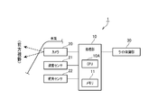
- FIG. 1 is a block diagram illustrating a schematic configuration of a light control system according to the embodiment.
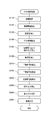
- FIG. 2 is a flowchart showing the light control process of the embodiment executed by the processing unit of the light control system.
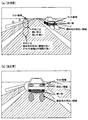
- FIG. 3 shows an example of a captured image.
- FIG. 3A shows an imaging screen in which an oncoming vehicle is reflected
- FIG. 3B shows an imaging screen in which a preceding vehicle is reflected.
- FIG. 1 shows a light control system 1 having a function of a vehicle light source detection device according to the present invention.
- This system 1 is mounted on a vehicle such as a passenger car, for example, and when there is another vehicle around the vehicle, the direction of the optical axis of the headlight of the vehicle is changed downward to dazzle the driver of the other vehicle. It has the function to prevent. This change in the direction of the optical axis is executed when another vehicle exists within a range in which the above-described dazzling may occur.
- the light control system 1 includes a processing unit 10, a camera 20, a speed sensor 21, a rudder angle sensor 22, and a light control unit 30.
- the camera 20 is arranged such that at least the irradiation range of the headlight in the traveling direction of the vehicle (particularly in front) is included in the imaging range, and is configured as a color camera that images the imaging range in color. Is sent to the processing unit 10.
- the speed sensor 21 and the rudder angle sensor 22 have a well-known configuration and are used for estimating the traveling direction of the vehicle.
- the speed sensor 21 and the rudder angle sensor 22 send detection results by themselves to the processing unit 10.
- the light control unit 30 receives the vehicle light detection result by the processing unit 10 and controls the direction of the optical axis of the headlight. Specifically, when a detection result indicating that there is a vehicle light in the captured image is received, the headlight is switched to a low beam, and when a detection result indicating that there is no vehicle light in the captured image is received, the high beam is switched. Note that the light control unit 30 may be configured to move the direction of the optical axis in a direction in which no other vehicle exists (for example, downward or leftward) in response to a command from the processing unit 10.
- the processing unit 10 is configured as a well-known microcomputer including a CPU 10A and a memory 11 such as a ROM and a RAM, and will be described later based on a program (including a vehicle light source detection program) stored in the memory 11. Various processes such as a write control process are performed. Further, the memory 11 includes parameters indicating characteristics of the lights of the vehicle (including values corresponding to parameters such as position, size, color, height, distance between paired lights, behavior, etc.), vehicle The parameter which shows the characteristic of light sources other than is stored. The parameters stored in the memory 11 are used when a light source indicating a vehicle light is identified and detected from a captured image in a light source other than the vehicle light.
- the light control process is a process for controlling the direction of the optical axis of the headlight by identifying and detecting the light source indicating the vehicle light from the captured image.
- the light control process is a process that is started when the vehicle is turned on, and thereafter executed every predetermined period (for example, every 100 ms). Specifically, as shown in FIG. 2, first, an image captured by the camera 20 is acquired (step S110).
- road surface information is extracted (step S120).
- a road surface area in the captured image is specified using a known white line detection technique or the like. For example, white lines existing on the left and right of the traveling area of the host vehicle are detected, and the area inside these white lines is set as a road surface area.
- the road surface color is detected by calculating the average color of the specified road surface area (step S130).
- the color of the specific position (arbitrary part) on the road surface may be the color of the road surface.
- light candidates are extracted from the captured image (step S140). In this processing, the entire region as one light source in the captured image and including the smallest region is cut out in a rectangle (rectangle), and labeling (numbering) is performed for each cut out region. In this process, a larger area is extracted as the light source in the captured image is larger.
- a light candidate feature amount is calculated, and the probability that the light source is a vehicle light source is set according to the feature amount (step S150).
- the still image level feature amount, the pair feature amount, and the time series feature amount are obtained.
- the still image level feature amount represents a feature amount based on the color or shape of a single light source included in the light source
- the pair feature amount represents a feature amount based on the relationship with other light sources positioned in the horizontal direction
- the time-series feature amount represents It represents the feature value based on the result of tracking the light source.
- the accuracy that the light source is a vehicle light source is obtained according to each feature amount.
- the accuracy of the vehicle light source is calculated by taking a weighted average of each feature amount.
- each feature-value and the accuracy which is a vehicle light source may be matched experimentally beforehand.
- a light source having a candidate color is detected (step S160).
- the average color of the region extracted as the light source is selected as the lamp color used as a vehicle light such as a headlamp, tail lamp, fog lamp, or number lamp.
- a characteristic tendency when the light source is a vehicle light source is detected (steps S210 to S230).
- the light source is the light source of the vehicle and the target vehicle travels from the front of the host vehicle toward the host vehicle, as shown in FIG. 3A, immediately below the light source (light candidate).
- the light source light candidate
- the reflected light of the light source from the road surface has a similar color to the light source. Also, if the light source is not from a vehicle, there is no dark area immediately below the light source or there is a dark area in the area away from the light source, and there is no reflected light from the light source or further away from the light source. Tend to be.
- the target vehicle is a preceding vehicle that travels in front of the host vehicle in the same direction as the host vehicle, as in the case of the oncoming vehicle, as shown in FIG.
- an area brighter than the brightness of the road surface (which can be calculated from the color of the road surface) within a certain distance below the selected light source is detected (step S210).
- the constant distance here refers to, for example, a range of several meters from the light source, and the distance is converted into the number of pixels according to the position of the light source, and a bright region is detected within the number of pixels.
- step S220 an area where the luminance is darker than the luminance of the road surface within a certain distance below the light source is detected (step S220).
- the fixed distance here is generally set within a range of, for example, about 50 cm from the light source in consideration of the height at which the headlamp and the tail lamp are arranged and the distance to the area where the shadow of the vehicle exists.
- step S230 a region where the luminance is brighter than the luminance of the road surface in the region located on the side of the light source is detected.
- the process of step S230 is performed only when the color of the light source is a color indicating a tail lamp, and a bright area is detected within the range in which the headlight diffuses (within a range of several meters). If the bright area is too far away from the light source, a disturbance such as a guardrail may be detected as a bright area. In order to reduce the influence of this disturbance, the bright area is detected only within the range where the headlight diffuses. Within range.
- step S240 the dark area that is the shadow of the vehicle itself immediately below the light source, the reflected light area of the light source below the light source, and the side of the light source of the color that indicates the taillight.
- the probability that the vehicle is a vehicle is set higher with respect to the light source from which any one of the bright areas is detected (step S240). At this time, a higher probability may be set for a light source in which a plurality of areas among the above-described areas are detected. Note that in the process of step S240, in the processes of steps S210 to S230, the dark area that is the shadow of the vehicle itself immediately below the light source, the reflected light area of the light source below the light source, and the color indicating the taillight.
- a light source that did not detect any of the bright areas on the side of the light source (there is no dark area directly under the light source or a dark area in the area away from the light source, or there is reflected light from the light source)
- the probability of being a vehicle may be set lower with respect to a case where the area is further away from the light source.
- a preset threshold value is compared with a final probability, and a light source having a probability less than the threshold value is removed as a disturbance to determine the remaining light source as a vehicle light (step S250). Then, the detection result of the vehicle light is sent to the light control unit 30 (step S260), and the light control process is terminated.
- the processing unit 10 acquires a captured image obtained by capturing the traveling direction of the host vehicle, and extracts a light source from the captured image. Then, the probability that the light source is a vehicle light source that represents the light source derived from the vehicle is calculated based on the light source parameter that represents the parameter relating to the light source, and a dark part that represents a darker part than the surroundings under the light source is extracted. Furthermore, the accuracy of being a vehicle light source is set higher than the light source from which the dark portion is extracted, and a light source having an accuracy equal to or higher than a preset reference value is estimated as the vehicle light source.
- the light source parameter in the present embodiment represents information for identifying the light source.
- the light source parameter includes at least one of information such as the color, shape, brightness, position, and size of the light source.
- the processing unit 10 has a color similar to the color of the light source and has a color set in advance as the color of the light source of the vehicle, and represents a similar color representing another light source below the light source. Extract the light source. Furthermore, the probability of being a vehicle light source is set higher than the light source from which the dark portion and the similar color light source are extracted.
- a light control system 1 it is a color set as a light source of a vehicle when the light source is reflected on the road surface below the light source, and when a reflected light of a similar color to the light source is detected, Therefore, the vehicle light source can be detected with higher accuracy.
- the processing unit 10 sets the probability that the light source is a vehicle light source according to the distance from the light source to the similar color light source.
- the height from the road surface to the light source is detected as the distance from the light source to the similar color light source, and the vehicle according to the degree to which this distance matches the distance set as the light source of the vehicle.
- the accuracy of the light source can be set. Therefore, the vehicle light source can be detected with higher accuracy.
- the processing unit 10 extracts a tail light source representing a light source having a color similar to the tail lamp from the light source, and extracts a bright part representing a brighter region than the surroundings in the left and right regions of the light source, Furthermore, the probability that the light source corresponding to the bright part is a vehicle light source is set higher than the light source that is a tail light source.
- a tail light source when a tail light source is detected and a bright part is detected by a headlight emitted from a preceding vehicle toward the traveling direction of the host vehicle, the light source that is a tail light source is detected.
- the accuracy of the vehicle light source can be set high. Therefore, the vehicle light source can be detected with higher accuracy.
- the color near the center may be detected, or the average color of an area having a certain luminance or higher may be detected.
- the embodiments of the present invention are not limited to the above-described embodiments, and various forms can be adopted as long as they belong to the technical scope of the present invention.
- the processing unit 10 of this embodiment corresponds to a vehicle light source detection device, and the processing of S110 of this embodiment corresponds to an image acquisition unit.
- the process of S140 of this embodiment corresponds to a light source extraction unit, and the process of S150 of this embodiment corresponds to an accuracy calculation unit.
- process of S160 of this embodiment corresponds to tail light source extraction means
- process of S210 of this embodiment corresponds to similar color light source extraction means
- process of S220 of the present embodiment corresponds to dark part extraction means
- process of S230 of the present embodiment corresponds to bright part extraction means.
- process of S240 of the present embodiment corresponds to accuracy correction means
- process of S250 of the present embodiment corresponds to vehicle light source estimation means
- SYMBOLS 1 Light control system, 10 ... Processing part, 11 ... Memory, 20 ... Camera, 21 ... Speed sensor, 22 ... Steering angle sensor, 30 ... Light control part.
Landscapes
- Engineering & Computer Science (AREA)
- Physics & Mathematics (AREA)
- General Physics & Mathematics (AREA)
- Spectroscopy & Molecular Physics (AREA)
- Multimedia (AREA)
- Theoretical Computer Science (AREA)
- Mechanical Engineering (AREA)
- Image Analysis (AREA)
- Traffic Control Systems (AREA)
- Lighting Device Outwards From Vehicle And Optical Signal (AREA)
- Image Processing (AREA)
Abstract
Dans un système de commande d'éclairage (1) selon l'invention, une image capturée est acquise dans la direction de déplacement d'un véhicule (S110) et des sources lumineuses sont extraites de l'image capturée (S140). De plus, les probabilités d'estimation que les sources lumineuses sont les sources lumineuses de véhicule provenant de véhicules sont calculées sur la base de paramètres de sources lumineuses pour identifier les sources lumineuses (S150). Les zones obscures qui sont plus obscures que la zone autour de la partie inférieure des sources lumineuses sur l'image capturée sont extraites (S220). En outre, les probabilités sont plus élevées pour les sources lumineuses à partir desquelles les zones obscures ont été extraites (S240). Les sources lumineuses ayant des probabilités supérieures ou égales à une valeur de référence prédéfinie sont censées être des sources lumineuses d'autres véhicules (S250). En d'autres termes, la probabilité pour qu'elles soient une source lumineuse de véhicule est élevée lorsqu'une zone obscure détectée en tant que l'ombre d'un véhicule a été détectée.
Priority Applications (2)
| Application Number | Priority Date | Filing Date | Title |
|---|---|---|---|
| US14/399,399 US9977974B2 (en) | 2012-05-09 | 2013-05-08 | Method and apparatus for detecting light source of vehicle |
| US15/960,856 US10839235B2 (en) | 2012-05-09 | 2018-04-24 | Method and apparatus for detecting light source of vehicle |
Applications Claiming Priority (2)
| Application Number | Priority Date | Filing Date | Title |
|---|---|---|---|
| JP2012-107648 | 2012-05-09 | ||
| JP2012107648A JP5962193B2 (ja) | 2012-05-09 | 2012-05-09 | 車両光源検出装置および車両光源検出プログラム |
Related Child Applications (2)
| Application Number | Title | Priority Date | Filing Date |
|---|---|---|---|
| US14/399,399 A-371-Of-International US9977974B2 (en) | 2012-05-09 | 2013-05-08 | Method and apparatus for detecting light source of vehicle |
| US15/960,856 Continuation US10839235B2 (en) | 2012-05-09 | 2018-04-24 | Method and apparatus for detecting light source of vehicle |
Publications (1)
| Publication Number | Publication Date |
|---|---|
| WO2013168744A1 true WO2013168744A1 (fr) | 2013-11-14 |
Family
ID=49550778
Family Applications (1)
| Application Number | Title | Priority Date | Filing Date |
|---|---|---|---|
| PCT/JP2013/062950 WO2013168744A1 (fr) | 2012-05-09 | 2013-05-08 | Procédé et dispositif de détection de sources lumineuses d'un véhicule |
Country Status (3)
| Country | Link |
|---|---|
| US (2) | US9977974B2 (fr) |
| JP (1) | JP5962193B2 (fr) |
| WO (1) | WO2013168744A1 (fr) |
Families Citing this family (6)
| Publication number | Priority date | Publication date | Assignee | Title |
|---|---|---|---|---|
| JP5962193B2 (ja) * | 2012-05-09 | 2016-08-03 | 株式会社デンソー | 車両光源検出装置および車両光源検出プログラム |
| GB201405527D0 (en) * | 2014-03-27 | 2014-05-14 | Mill Facility The Ltd | A driveable vehicle unit |
| JP6034923B1 (ja) * | 2015-06-26 | 2016-11-30 | 富士重工業株式会社 | 車外環境認識装置 |
| DE102018208739A1 (de) * | 2018-06-04 | 2019-12-05 | Conti Temic Microelectronic Gmbh | Abschätzung von Ortskoordinaten von Lichtquellen in Umgebungsbildern |
| DE102018216562A1 (de) * | 2018-09-27 | 2020-04-02 | Conti Temic Microelectronic Gmbh | Verfahren zum Detektieren von Lichtverhältnissen in einem Fahrzeug |
| KR20210017525A (ko) | 2019-08-08 | 2021-02-17 | 삼성전자주식회사 | 거리 추정 장치 및 이의 동작 방법 |
Citations (5)
| Publication number | Priority date | Publication date | Assignee | Title |
|---|---|---|---|---|
| JP2007272785A (ja) * | 2006-03-31 | 2007-10-18 | Matsushita Electric Ind Co Ltd | 画像処理式車両検出装置及び画像処理式車両検出方法 |
| JP2008287367A (ja) * | 2007-05-15 | 2008-11-27 | Univ Nihon | 車両検出システム |
| JP2009032030A (ja) * | 2007-07-26 | 2009-02-12 | Koito Ind Ltd | 車両検出装置 |
| JP2011098579A (ja) * | 2009-11-04 | 2011-05-19 | Niles Co Ltd | 車両のテールランプ検出装置 |
| JP2011103070A (ja) * | 2009-11-11 | 2011-05-26 | Toyota Motor Corp | 夜間車両検知装置 |
Family Cites Families (12)
| Publication number | Priority date | Publication date | Assignee | Title |
|---|---|---|---|---|
| JPH06276524A (ja) | 1993-03-19 | 1994-09-30 | Toyota Motor Corp | 対向車両認識装置 |
| AU2003298558A1 (en) * | 2002-08-21 | 2004-05-04 | Gentex Corporation | Image acquisition and processing methods for automatic vehicular exterior lighting control |
| JP2006185410A (ja) | 2004-12-02 | 2006-07-13 | Nissan Motor Co Ltd | 夜間移動体報知装置及び夜間移動体報知方法 |
| TWI302879B (en) * | 2006-05-12 | 2008-11-11 | Univ Nat Chiao Tung | Real-time nighttime vehicle detection and recognition system based on computer vision |
| JP4853160B2 (ja) * | 2006-08-02 | 2012-01-11 | 株式会社デンソー | 車両検出装置及びヘッドランプ制御装置 |
| JP4321591B2 (ja) * | 2007-01-11 | 2009-08-26 | 株式会社デンソー | 車載霧判定装置 |
| JP4914233B2 (ja) * | 2007-01-31 | 2012-04-11 | 富士重工業株式会社 | 車外監視装置 |
| JP4937199B2 (ja) * | 2008-06-25 | 2012-05-23 | 日立オートモティブシステムズ株式会社 | オートライト装置 |
| CN102834309B (zh) * | 2010-02-26 | 2016-12-21 | 金泰克斯公司 | 自动车辆设备监控、报警和控制系统 |
| JP5656732B2 (ja) * | 2011-05-02 | 2015-01-21 | 株式会社デンソー | 衝突確率演算装置、および衝突確率演算プログラム |
| JP5716680B2 (ja) * | 2012-01-10 | 2015-05-13 | 株式会社デンソー | 先行車両選択装置および車間制御装置 |
| JP5962193B2 (ja) * | 2012-05-09 | 2016-08-03 | 株式会社デンソー | 車両光源検出装置および車両光源検出プログラム |
-
2012
- 2012-05-09 JP JP2012107648A patent/JP5962193B2/ja not_active Expired - Fee Related
-
2013
- 2013-05-08 US US14/399,399 patent/US9977974B2/en active Active
- 2013-05-08 WO PCT/JP2013/062950 patent/WO2013168744A1/fr active Application Filing
-
2018
- 2018-04-24 US US15/960,856 patent/US10839235B2/en active Active
Patent Citations (5)
| Publication number | Priority date | Publication date | Assignee | Title |
|---|---|---|---|---|
| JP2007272785A (ja) * | 2006-03-31 | 2007-10-18 | Matsushita Electric Ind Co Ltd | 画像処理式車両検出装置及び画像処理式車両検出方法 |
| JP2008287367A (ja) * | 2007-05-15 | 2008-11-27 | Univ Nihon | 車両検出システム |
| JP2009032030A (ja) * | 2007-07-26 | 2009-02-12 | Koito Ind Ltd | 車両検出装置 |
| JP2011098579A (ja) * | 2009-11-04 | 2011-05-19 | Niles Co Ltd | 車両のテールランプ検出装置 |
| JP2011103070A (ja) * | 2009-11-11 | 2011-05-26 | Toyota Motor Corp | 夜間車両検知装置 |
Also Published As
| Publication number | Publication date |
|---|---|
| US20180239974A1 (en) | 2018-08-23 |
| JP5962193B2 (ja) | 2016-08-03 |
| US9977974B2 (en) | 2018-05-22 |
| US20150098612A1 (en) | 2015-04-09 |
| US10839235B2 (en) | 2020-11-17 |
| JP2013235436A (ja) | 2013-11-21 |
Similar Documents
| Publication | Publication Date | Title |
|---|---|---|
| JP4544233B2 (ja) | 車両検出装置及びヘッドランプ制御装置 | |
| US10442343B2 (en) | Vehicle exterior environment recognition apparatus | |
| US10286834B2 (en) | Vehicle exterior environment recognition apparatus | |
| US10839235B2 (en) | Method and apparatus for detecting light source of vehicle | |
| JP5692180B2 (ja) | 車両光源検出装置、ライト制御装置、および車両光源検出プログラム | |
| JP4853160B2 (ja) | 車両検出装置及びヘッドランプ制御装置 | |
| US8232895B2 (en) | Vehicle detection apparatus, vehicle detection program and light control apparatus | |
| US9317757B2 (en) | Method and apparatus for detecting a rear vehicle light | |
| JP5680573B2 (ja) | 車両の走行環境認識装置 | |
| JP4935586B2 (ja) | 画像処理装置、車載用画像処理装置、車載用画像表示装置及び車両制御装置 | |
| US8315766B2 (en) | Process for detecting a phenomenon limiting the visibility for a motor vehicle | |
| US9493108B2 (en) | Apparatus for detecting other vehicle lights and light control apparatus for vehicles | |
| JP5884635B2 (ja) | 走行環境検出装置、走行環境検出プログラム、およびライト制御装置 | |
| JP2009067084A (ja) | ライト制御装置 | |
| JP2008028957A (ja) | 車両用画像処理装置 | |
| US9367749B2 (en) | Object detection apparatus | |
| JP2014024411A (ja) | 自発光光源検出装置、ライト制御装置、および自発光光源検出プログラム | |
| CN111046741A (zh) | 车道线识别的方法和装置 | |
| JP7201706B2 (ja) | 画像処理装置 | |
| JP2013028239A (ja) | ライト検出装置、ライト検出プログラム、およびライト制御装置 | |
| JP2022108251A (ja) | オブジェクト認識制御装置およびオブジェクト認識制御方法 | |
| JP2013244893A (ja) | ライト制御装置、およびライト制御プログラム |
Legal Events
| Date | Code | Title | Description |
|---|---|---|---|
| 121 | Ep: the epo has been informed by wipo that ep was designated in this application |
Ref document number: 13788072 Country of ref document: EP Kind code of ref document: A1 |
|
| WWE | Wipo information: entry into national phase |
Ref document number: 14399399 Country of ref document: US |
|
| NENP | Non-entry into the national phase |
Ref country code: DE |
|
| 122 | Ep: pct application non-entry in european phase |
Ref document number: 13788072 Country of ref document: EP Kind code of ref document: A1 |