WO2013168568A1 - 空気浄化装置 - Google Patents
空気浄化装置 Download PDFInfo
- Publication number
- WO2013168568A1 WO2013168568A1 PCT/JP2013/062046 JP2013062046W WO2013168568A1 WO 2013168568 A1 WO2013168568 A1 WO 2013168568A1 JP 2013062046 W JP2013062046 W JP 2013062046W WO 2013168568 A1 WO2013168568 A1 WO 2013168568A1
- Authority
- WO
- WIPO (PCT)
- Prior art keywords
- gas
- water
- liquid contact
- contact portion
- fiber assembly
- Prior art date
- Legal status (The legal status is an assumption and is not a legal conclusion. Google has not performed a legal analysis and makes no representation as to the accuracy of the status listed.)
- Ceased
Links
Images

Classifications
-
- B—PERFORMING OPERATIONS; TRANSPORTING
- B01—PHYSICAL OR CHEMICAL PROCESSES OR APPARATUS IN GENERAL
- B01D—SEPARATION
- B01D47/00—Separating dispersed particles from gases, air or vapours by liquid as separating agent
- B01D47/14—Packed scrubbers
-
- B—PERFORMING OPERATIONS; TRANSPORTING
- B01—PHYSICAL OR CHEMICAL PROCESSES OR APPARATUS IN GENERAL
- B01D—SEPARATION
- B01D53/00—Separation of gases or vapours; Recovering vapours of volatile solvents from gases; Chemical or biological purification of waste gases, e.g. engine exhaust gases, smoke, fumes, flue gases, aerosols
- B01D53/14—Separation of gases or vapours; Recovering vapours of volatile solvents from gases; Chemical or biological purification of waste gases, e.g. engine exhaust gases, smoke, fumes, flue gases, aerosols by absorption
- B01D53/18—Absorbing units; Liquid distributors therefor
-
- B—PERFORMING OPERATIONS; TRANSPORTING
- B01—PHYSICAL OR CHEMICAL PROCESSES OR APPARATUS IN GENERAL
- B01D—SEPARATION
- B01D2247/00—Details relating to the separation of dispersed particles from gases, air or vapours by liquid as separating agent
- B01D2247/04—Regenerating the washing fluid
-
- B—PERFORMING OPERATIONS; TRANSPORTING
- B01—PHYSICAL OR CHEMICAL PROCESSES OR APPARATUS IN GENERAL
- B01D—SEPARATION
- B01D2247/00—Details relating to the separation of dispersed particles from gases, air or vapours by liquid as separating agent
- B01D2247/10—Means for removing the washing fluid dispersed in the gas or vapours
- B01D2247/107—Means for removing the washing fluid dispersed in the gas or vapours using an unstructured demister, e.g. a wire mesh demister
-
- B—PERFORMING OPERATIONS; TRANSPORTING
- B01—PHYSICAL OR CHEMICAL PROCESSES OR APPARATUS IN GENERAL
- B01D—SEPARATION
- B01D2247/00—Details relating to the separation of dispersed particles from gases, air or vapours by liquid as separating agent
- B01D2247/14—Fan arrangements for providing induced draft
-
- B—PERFORMING OPERATIONS; TRANSPORTING
- B01—PHYSICAL OR CHEMICAL PROCESSES OR APPARATUS IN GENERAL
- B01D—SEPARATION
- B01D2257/00—Components to be removed
- B01D2257/30—Sulfur compounds
- B01D2257/302—Sulfur oxides
-
- B—PERFORMING OPERATIONS; TRANSPORTING
- B01—PHYSICAL OR CHEMICAL PROCESSES OR APPARATUS IN GENERAL
- B01D—SEPARATION
- B01D2258/00—Sources of waste gases
- B01D2258/06—Polluted air
Definitions
- the present invention relates to an air purification device.
- a gas-liquid contact type air purifier scrubbers that are often used in air conditioners and external air conditioners of buildings are known, and in particular, fillers such as Raschig rings and terralet packing are used.
- a packed tower type is known. Although the packed tower type is suitable for industrial use, it increases the height of the packed bed and increases the size of the equipment, so that the outside air introduced into the living space in homes, that is, houses such as detached houses and apartment buildings, It is not preferable as a use for purifying the air circulating in the living space.
- the air-liquid contact type air purification device it has been proposed to fill the gas-liquid contact chamber with various fillers, and it is expected to realize downsizing of the device.
- a filler for example, it has been proposed to use a honeycomb structure (see Patent Document 1) or a fiber assembly (see Patent Document 2).
- the filler in the gas-liquid contact chamber is required to exhibit high removal performance with respect to fine particles and gaseous substances while suppressing an increase in pressure loss.
- the filler having the honeycomb structure described in Patent Document 1 is effective for reducing the pressure loss, but is mainly used for the purpose of removing viruses in the air.
- the removal performance of the particulate matter is not high.
- the fiber assembly described in Patent Document 2 does not take into consideration pressure loss and removal performance of fine particles, gaseous substances, and the like.
- an object of the present invention is to provide an air purification device that removes particulates and gaseous substances contained in air with high efficiency while suppressing an increase in pressure loss.
- an air purification device of the present invention is an intake port and an exhaust port provided in a housing, and the exhaust port is located above the intake port.
- the air-liquid contact part where the air introduced into the housing from the intake port contacts the cleaning water
- the upper part of the gas-liquid contact part is provided for cleaning the gas-liquid contact part.
- sprinkling means for sprinkling water
- cleaning water storage means for storing cleaning water
- cleaning water circulation means for circulating the cleaning water by supplying the cleaning water stored in the cleaning water storage means to the watering means. is doing.
- the gas-liquid contact portion is a mat-like fiber assembly having different fiber densities in the thickness direction, and one surface of the fiber assembly has a low density and undulation shape, and the other surface of the fiber assembly.
- an air purification device that removes particulates and gaseous substances contained in air with high efficiency while suppressing an increase in pressure loss.
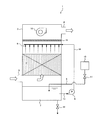
- FIG. 1 is a schematic view showing a configuration of an embodiment of an air purification device of the present invention.
- the air purification device 1 includes an intake port 3 provided on the lower side surface of the housing 2, an exhaust port 4 provided on the upper side surface of the housing 2, and an interior of the housing 2.
- a circulation pump (washing water circulation means) 8 for circulating the washing water by supplying the washing water in the circulation tank 7 to the watering nozzle 6 is provided.
- the air purification device 1 causes the air-liquid contact portion 5 to bring the air introduced from the air inlet 3 into the housing 2 and the cleaning water sprayed from the water spray nozzle 6 into contact with each other. Is supposed to be washed.
- the gas-liquid contact portion 5 is composed of a mat-like fiber assembly having a specific configuration. Thereby, the air purification apparatus 1 of this embodiment can remove the particulates and gaseous substances contained in the air with high efficiency while suppressing an increase in pressure loss.
- the detailed configuration of the gas-liquid contact portion 5, particularly the fiber assembly will be described later.
- the watering nozzle 6 is capable of spraying water having a mist and a small particle size, and therefore, a spray type that can efficiently wet the gas-liquid contact portion 5, particularly a fan-shaped spray nozzle or an annular spray nozzle is suitable. is there.
- the fan-type spray nozzle has a small amount of spray water, can disperse the spray water, and can spray water over a wide range.
- the annular spray nozzle is not easily clogged, and can spray water over a wide range by turbulently dispersing the sprayed water in the rising airflow of the air to be treated.
- spray water from the annular spray nozzle collides with spray water from adjacent nozzles or intersecting spray water, resulting in water droplets becoming coarse and / or finer. become.
- the coarse water droplets fall to wet the gas-liquid contact part 5 and wash away the fine particles and gaseous substances taken in.
- the fine water droplets float and repeat micronization and coarsening. Become. It is preferable that a plurality of fan spray nozzles and annular spray nozzles are arranged so that the spray water intersects or is parallel.
- An external water source 10 is connected to the circulation tank 7 via a pipe 9, and cleaning water from the external water source 10 can be replenished and replaced by controlling a water supply valve 11 provided in the pipe 9.
- a drain valve 12 for draining water is provided on the bottom surface of the circulation tank 7.
- the circulation pump 8 has a primary side (suction side) connected to the circulation tank 7 via a pipe 13, and a secondary side (discharge side) connected to the watering nozzle 6 via a pipe 14. Water can be circulated.
- the circulation pump is provided outside the housing 2, but may be provided inside the housing 2 as long as the cleaning water is circulated. Further, the circulation pump 8 may be a submersible pump provided in the circulation tank 7.
- Wash water stored in the circulation tank 7 and used for purifying air is not particularly limited as long as it is clean water, and tap water, well water, distilled water, pure water, electrolyzed water, or the like can be used. .
- the air purification device 1 includes an eliminator (a drip-proof plate) 15 that is provided above the watering nozzle 6 and prevents the spray water from scattering from the watering nozzle 6.
- humidity adjusting means such as a desiccant rotor may be provided above the eliminator 15.
- an upward driving force is applied to the air introduced from the intake port 3, and the air that has passed through the gas-liquid contact portion 5 is discharged from the exhaust port 4.
- a blower 16 is installed. Note that the air introduced from the intake port 3 only needs to be discharged from the exhaust port 4. Instead of the blower 16, an exhaust unit that exhausts air from the exhaust port 4 is provided outside the housing 2. It may be done.
- the inside of the housing 2 is in a decompressed state, and the air to be purified is introduced into the housing 2 from the air inlet 3.
- the introduced air is given an upward driving force by the blower 16, flows inside the housing 2 from the bottom to the top, and reaches the gas-liquid contact portion 5.
- the wash water stored in the circulation tank 7 is supplied to the watering nozzle 6 by the circulation pump 8.
- the washing water supplied to the watering nozzle 6 is sprayed to the gas-liquid contact part 5 by the watering nozzle 6 and retained by the fiber assembly of the gas-liquid contact part 5.
- the air rising from below the gas-liquid contact part 5 makes gas-liquid contact with the fiber assembly of the gas-liquid contact part 5, and particulate matter and gaseous chemical substances in the air are removed by the washing water. .
- the purified air is discharged from the exhaust port 4 by the blower 16.
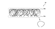
- FIG. 2A is a schematic cross-sectional view of a fiber assembly constituting the gas-liquid contact portion 5
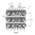
- FIG. 2B is a schematic cross-sectional view showing the configuration of the gas-liquid contact portion 5 of the present embodiment.
- the fiber assembly 50 constituting the gas-liquid contact portion 5 is formed in a three-dimensional nonwoven fabric shape in which synthetic resin is processed into a curl shape and a part of the fibers are bonded to each other.
- the fibers processed into the curled shape of the fiber assembly 50 are non-uniformly arranged, and most of the tip portions (cut portions) are located on one surface side.
- the fiber assembly 50 has one surface 50a having a low density and undulating shape (rough and rough), and the other surface 50b having a high density and a flat surface. It has a (flat) shape, and the fiber density is different in the thickness direction from one surface 50a to the other surface 50b.
- washing water is sprinkled on the flat surface 50b of the fiber assembly 50, and air flows from the rough and rough surface 50a. That is, the fiber assembly 50 is installed in the air purification device 1 so that the rough and rough surface 50a constitutes the “lower surface” and the flat surface 50b constitutes the “upper surface”.
- the raw material of the fibers constituting the fiber assembly 50 may be any material that can be processed into fibers, for example, polyamides such as wholly aromatic polyamide, nylon 6 and nylon 66; polyesters such as polyethylene terephthalate and polybutylene terephthalate; Poly (halogenated olefins) such as vinyl chloride, polyvinylidene chloride, polyvinylidene fluoride, and polytetrafluoroethylene; Nitrile monomers such as polyacrylonitrile and polymethacrylonitrile; polyvinyl acetate, vinyl polypropionate, polyvinyl alcohol, etc. Polyvinyl esters and hydrolysis products thereof; celluloses such as cellulose, acetyl cellulose, and rayon; and polyolefins such as polyethylene, polypropylene, and ethylene-vinyl acetate copolymer.
- polyamides such as wholly aromatic polyamide, nylon 6 and nylon 66
- polyesters such as polyethylene terephthalate and
- the fiber assembly 50 is used as the gas-liquid contact portion 5, it is desirable that the fiber assembly 50 is composed of fibers that have almost no water absorption and have chemical resistance. From such points, it is desirable to use polyvinylidene chloride or the like among the above-mentioned fiber raw materials.
- a method for bonding the fiber assembly 50 (a method for creating the assembly), a thermal bond method in which fibers are melted and bonded by heat, a chemical bond method in which fibers are bonded using an adhesive, or a needle with a barb
- the needle punch method etc. which bond a fiber mechanically by piercing and the like may be mentioned, and any method may be used.
- Saran Lock (registered trademark) of Asahi Kasei Home Products Co., Ltd. may be mentioned.
- Saran lock is a three-dimensional nonwoven fabric obtained by curling Saran (registered trademark) fiber, which is a highly flame-retardant fiber of the material itself, into a nonwoven fabric by curling it into a spring shape and coating and bonding with Saran latex.
- Saran lock is suitably used because it has a large space and surface area, low ventilation resistance, excellent filtration efficiency, and a large dust collection capacity.
- each of the gas-liquid contact portion 5 of the present embodiment has the same configuration as the fiber assembly 50 shown in FIG. 2A, and three layers of two types of fiber assemblies having different average fiber densities.
- a stacked body 51 is stacked.
- the gas-liquid contact portion 5 includes an upper layer 52 made of a fiber assembly having a relatively low average fiber density (low density fiber assembly) and a fiber assembly having a relatively high average fiber density (high density).
- a laminated body 51 composed of an intermediate layer 53 made of a fiber assembly) and a lower layer 54 made of a low-density fiber assembly similar to the upper layer 52.
- the “average fiber density” indicates how densely the fibers are arranged as a whole of the fiber assembly, and is expressed by, for example, the surface area (specific surface area) of the fibers per unit volume.
- the low-density fiber assembly of the upper layer 52 can retain water by uniformly dispersing the cleaning water sprayed from the water spray nozzle 6 on a flat upper surface. This uniformly retained washing water flows down due to gravity and capillary action, and is uniformly supplied to the entire intermediate layer (high-density fiber assembly) having a high removal performance of fine particles and gaseous substances. As a result, the high removal performance of the intermediate layer (high-density fiber assembly) can be efficiently exhibited with respect to fine particles, gaseous substances, and the like. In addition, since the average fiber density of the upper layer 52 is a low density, the water retention state on the upper surface does not become an excessive water retention state (water seal state) enough to increase the pressure loss.
- the high-density fiber assembly of the intermediate layer 53 can appropriately retain the wash water that has flowed down from the upper layer 52, and thus has a high removal performance with respect to fine particles, gaseous substances, and the like.
- the gas-liquid contact area can be increased, and the removal performance for fine particles, gaseous substances and the like can be improved.
- the low-density fiber assembly of the lower layer 54 also has a rectifying action of the air to be treated that flows from the lower surface.
- water droplets roll up on the upper surface of the fiber assembly of each layer 52-54.
- the gas-liquid contact portion 5 of the present embodiment has a structure capable of increasing the specific surface area of the filler (fiber assembly) while suppressing an increase in pressure loss due to water sealing as much as possible. Yes. Thereby, the contact opportunity of to-be-processed air and washing
- the configuration as described above is advantageous in that it makes it easy to wash away fine particles, gaseous substances, and the like trapped in the fiber assembly.
- the gas-liquid contact part 5 was comprised from the laminated body by which two types of fiber aggregates from which an average fiber density differs were laminated
- the average fiber density of the fiber assembly to be used may be more than two types, for example, three types. Further, four or more fiber assemblies may be laminated.
- the fiber assembly constituting the lowermost layer is a fiber assembly having the lowest average fiber density. This is for preventing the lower surface of the fiber assembly from being water-sealed in the lowermost layer and suppressing an increase in pressure loss.
- the fiber aggregate constituting the uppermost layer is also preferably a fiber aggregate having the lowest average fiber density. This is because the uppermost layer closest to the blower is most likely to have negative pressure, and if the uppermost layer is a fiber assembly having a high average fiber density, unevenness in the water retention state on the upper surface of the fiber assembly is likely to occur. It is.
- FIG. 3 shows the removal rate of fine particles having a particle diameter of 1 ⁇ m and the removal rate of sulfur dioxide (SO 2 ) by the gas-liquid contact portion 5 shown in FIG. It is the graph plotted with respect to ratio L / G of the watering flow rate L from the watering nozzle 6 with respect to the air volume (G).
- the removal rate data shown in FIG. 3 is a result obtained by performing measurement by changing the ratio L / G of the sprinkling flow rate L to the processing air flow rate G under the conditions of Example 5 described later.
- the ratio L / G of the sprinkling flow rate L to the treatment air volume G is preferably in the range of 0.5 to 3.0.
- the ratio L / G is 0.5 or more, SO 2 and fine particles can be sufficiently removed, and when the ratio L / G is 3.0 or less, an increase in differential pressure (pressure loss) is suppressed. , Sufficient removal performance can be exhibited.
- the air flow velocity (linear flow velocity) on the upper surface of the gas-liquid contact portion 5 is preferably equal to or higher than the free fall speed of the minimum water droplet diameter of water droplets sprayed on the upper surface of the gas-liquid contact portion 5.
- a part of water droplet sprayed with respect to the upper surface of the gas-liquid contact part 5 can be suspended.
- the suspended water droplets become larger by colliding with other water droplets while being diffused at random, and fall to the upper surface of the gas-liquid contact portion 5. For this reason, it is possible to spray the cleaning water more evenly and uniformly with respect to the upper surface of the gas-liquid contact portion 5, and to promote uniform spraying of the cleaning water on the upper surface of the gas-liquid contact portion 5.
- the suspended water droplets come into contact with air and fall onto the upper surface of the gas-liquid contact portion 5 while taking in the fine particles and gaseous substances contained in the air, the fine particle removal rate and the gaseous material removal rate are improved. Is also possible.
- the water spray nozzle 6 is located above the water spray nozzle 6. It is preferable that the provided eliminator 15 is installed at a position where the rolled up fine water droplets reach. As a result, the water to be treated can be removed by capturing the minute water droplets wound up by the air flow with the eliminator 15. Furthermore, a water film is formed on the lower surface of the eliminator 15 by minute water droplets, and fine particles and gaseous substances can be removed even with this water film.
- the eliminator 15 when the lower surface of the eliminator 15 is in an excessive water retaining state, it becomes a blowing resistance and increases pressure loss. Therefore, when the thickness of the water film formed on the lower surface of the eliminator 15 is increased, the weight of the water film exceeds the surface tension and drops as a droplet. It is preferable that a fiber assembly similar to the fiber assembly to be used is used, and the rough and rough surface is set to be the lower surface. For the same reason, it is preferable that the eliminator 15 is installed at a position where the spray water from the watering nozzle 6 is not in direct contact when there is no air flow.
- a fiber assembly having an average fiber density higher than that of the low-density fiber assembly constituting the upper layer 52 of the gas-liquid contact portion 5 may be used.
- a high-density fiber assembly constituting the intermediate layer 53 it is preferable to use a high-density fiber assembly constituting the intermediate layer 53.
- the eliminator 15 is only retained by the rolled up fine water droplets, and therefore does not enter a water-sealed state and does not increase pressure loss. Therefore, in order to remove fine particles and gaseous substances with high efficiency by the water film formed on the lower surface of the eliminator 15, it is preferable to use a high-density fiber assembly.
- Example 1 the removal rate of fine particles and SO 2 in the air was measured using the air purification apparatus shown in FIG.
- a single-layer fiber assembly is used as the gas-liquid contact portion.
- the fineness of the fiber is 600 to 1000 denier, the thickness is 50 mm, and the surface area (specific surface area) of the fiber per unit volume is 410 m 2 / m 3.
- Saran lock product number: OM-150
- Saran lock product number: CS-120 having a fiber fineness of 70 denier, a thickness of 20 mm, and a specific surface area of 890 m 2 / m 3 was used, and the flat surface was the upper surface.
- the treatment air flow rate of the air to be treated flowing into the gas-liquid contact portion was 150 m 3 / h, and the sprinkling flow rate of the washing water from the watering nozzle was 3 L / min. In this case, the ratio of the sprinkling flow rate to the processing air volume is 1.0.
- the fine particle removal rate was calculated from the fine particle concentration of the air to be treated and the fine particle concentration of the air purified by the particle counters respectively provided upstream of the intake port and downstream of the exhaust port.
- the inlet load at this time is 1 mg / m 3 for the test powder 1 type 11 of JIS Z 8901.
- the fine particle removal rate was measured for each particle size of the target fine particles.
- the SO 2 removal rate is calculated from the SO 2 concentration of the air to be treated and the SO 2 concentration of the purified air by SO 2 concentration meters provided on the upstream side of the intake port and the downstream side of the exhaust port, respectively. did.
- the inlet load at this time is 0.1 mg / m 3 .
- the differential pressure was measured by a differential pressure gauge as a pressure difference between the upstream side of the intake port and the downstream side of the gas-liquid contact portion (between the eliminator and the blower).
- Example 2 The same conditions as in Example 1 except that a laminated body in which two fiber assemblies (Saranlock (product number: OM-150)) of Example 1 were laminated with a flat surface as an upper surface was used as the gas-liquid contact portion. The measurement was performed.
- Saranlock product number: OM-150
- Example 3 As the gas-liquid contact portion, a single-layer fiber assembly is used. As the fiber assembly, a Saran lock (product number: CS-120) having a fiber fineness of 70 denier, a thickness of 20 mm, and a specific surface area of 890 m 2 / m 3 is used. And measurement was performed under the same conditions as in Example 1 except that the flat surface was the top surface.
- CS-120 Saran lock
- Example 4 The same conditions as in Example 1 except that the fiber assembly of Example 3 (Saranlok (product number: CS-120)) was laminated as a gas-liquid contact part, and a laminate in which two flat surfaces were laminated. The measurement was performed.
- Example 5 As a gas-liquid contact portion, a laminate having the structure shown in FIG. 2B, that is, an upper layer composed of a low-density fiber assembly, an intermediate layer composed of a high-density fiber assembly, and a lower layer composed of a low-density fiber assembly The measurement was performed under the same conditions as in Example 1 except that the laminated body was used.
- the fiber assembly of Example 1 (Saranlok (product number: OM-150))
- the high-density fiber assembly the fiber assembly of Example 3 (Saranlok (product number) : CS-120)).
- a laminated body laminates each fiber assembly with a flat surface as an upper surface, and the thickness is 120 mm.
- Example 6 Measurement was performed under the same conditions as in Example 5 except that another gas assembly was additionally installed below the lowermost fiber assembly of the laminate of Example 5 as the gas-liquid contact portion.
- the added fiber assembly is a high-density fiber assembly (Saranlok (product number: CS-120)) similar to the intermediate layer of Example 5. Therefore, the gas-liquid contact portion of Example 6 is different from the gas-liquid contact portion of Example 5 in that the gas-liquid contact portion includes four layers of fiber aggregates, and the lowermost layer is a high-density fiber aggregate.
- Example 1 As a gas-liquid contact portion, the fiber assembly of Example 1 (Saran lock (product number: OM-150)) was installed upside down, that is, a rough surface with a flat surface as a lower surface. Measurements were performed under the same conditions as in Example 1 except that the upper surface was installed.
- Example 2 The measurement was performed under the same conditions as in Example 2 except that the laminate of Example 2 was installed upside down as the gas-liquid contact portion.
- Example 3 Measurement was performed under the same conditions as in Example 3, except that the fiber assembly of Example 3 (Saranlock (product number: CS-120)) was installed upside down as the gas-liquid contact portion.
- Example 4 (Comparative Example 4) Measurement was performed under the same conditions as in Example 4 except that the laminate of Example 4 was installed upside down as the gas-liquid contact portion.
- Table 1 shows the particulate removal rate, the SO 2 removal rate, and the differential pressure in Examples 1 to 4 and Comparative Examples 1 to 4.
- Table 2 shows the particulate removal rate, the SO 2 removal rate, and the differential pressure in Example 3, Example 5, and Example 6.
- Example 5 it was confirmed that all of the removal rate of fine particles having a particle diameter of less than 5.0 ⁇ m, the removal rate of SO 2 , and the differential pressure were significantly improved as compared with Example 3, in particular, regarding the differential pressure. was confirmed to be reduced by about 90% or more.
- the intermediate layer of the laminate corresponds to the fiber assembly (high-density fiber assembly) of Example 3, that is, the upper and lower sides of the high-density fiber assembly are low-density fiber assemblies. It has a sandwiched configuration. Therefore, in Example 5, although the thickness of the gas-liquid contact portion is thick (Example 3: 20 mm, Example 5: 120 mm), particularly good results regarding the differential pressure are obtained. This is considered to be the effect of such a laminated structure.
- Example 6 by adding a high-density fiber assembly having high fine particle removal performance to the gas-liquid contact portion of Example 5, a better result than Example 5 was obtained with respect to the fine particle removal rate.
- the differential pressure there is a significant increase in the differential pressure. This is considered to be because in Example 6, the lowermost layer of the laminate was a high-density fiber assembly, and the water retention state on the lower surface further progressed and was water-sealed. Therefore, when Example 5 and Example 6 are compared, Example 5 is more favorable in terms of this differential pressure.
Landscapes
- Chemical & Material Sciences (AREA)
- Chemical Kinetics & Catalysis (AREA)
- Engineering & Computer Science (AREA)
- Analytical Chemistry (AREA)
- General Chemical & Material Sciences (AREA)
- Oil, Petroleum & Natural Gas (AREA)
- Separation Of Particles Using Liquids (AREA)
- Gas Separation By Absorption (AREA)
Description
本発明は、空気浄化装置に関する。
従来から、洗浄水と空気とを接触させることで、空気に含まれる微粒子やガス状物質等を除去する空気浄化装置が用いられている。
このような気液接触方式の空気浄化装置としては、ビルの空調機や外調機などに多く用いられているスクラバーが知られており、特に、ラシヒリングやテラレットパッキン等の充填材を用いた充填塔式のものが知られている。充填塔式は、産業用としては適しているが、充填層の高さが高くなり、装置が大型化するため、家庭用、すなわち、一戸建てや集合住宅などの住宅において居住空間に導入する外気や居住空間を循環する空気を浄化するための用途としては好ましくない。
一方で、気液接触方式の空気浄化装置においては、気液接触室にさまざまな充填材を充填することが提案されており、それにより、装置の小型化を実現することが期待されている。そのような充填材として、例えば、ハニカム構造を備えたもの(特許文献1参照)や繊維集合体(特許文献2参照)を用いることが提案されている。
ところで、気液接触室の充填材には、圧力損失の上昇を抑えながら、微粒子やガス状物質等に対して高い除去性能を発揮させることが求められている。
しかしながら、特許文献1に記載のハニカム構造を備えた充填材は、圧力損失を低下させるには有効であるが、主に空気中のウィルスを除去する目的で使用されるものであり、微粒子やガス状物質の除去性能が高いものではない。また、特許文献2に記載の繊維集合体は、圧力損失や微粒子やガス状物質等の除去性能について全く考慮されていない。
そこで本発明は、圧力損失の上昇を抑えながら、空気に含まれる微粒子やガス状物質を高効率で除去する空気浄化装置を提供することを目的とする。
上述した目的を達成するために、本発明の空気浄化装置は、筐体に設けられた吸気口および排気口であって、排気口が吸気口の上方に位置する、吸気口および排気口と、吸気口と排気口との間に設けられ、吸気口から筐体内に導入された空気が洗浄水に接触する気液接触部と、気液接触部の上方に設けられ、気液接触部に洗浄水を散水する散水手段と、洗浄水を貯留する洗浄水貯留手段と、洗浄水貯留手段に貯留された洗浄水を散水手段に供給することで、洗浄水を循環させる洗浄水循環手段と、を有している。気液接触部は、厚み方向で繊維密度が異なるマット状の繊維集合体であって、繊維集合体の一方の面が、低密度で起伏のある形状を有し、繊維集合体の他方の面が、高密度で平坦な形状を有する、繊維集合体を有している。繊維集合体は、一方の面が吸気口側に位置し、他方の面が排気口側に位置するように、吸気口と排気口との間に配置されている。
このような空気浄化装置では、気液接触部の繊維集合体で適度な保水状態が実現されるため、水封による圧力損失の上昇を抑えながら、微粒子やガス状物質等に対して高い除去性能を発揮させることが可能となる。
以上、本発明によれば、圧力損失の上昇を抑えながら、空気に含まれる微粒子やガス状物質を高効率で除去する空気浄化装置を提供することができる。
以下、図面を参照して、本発明の実施の形態について説明する。
図1は、本発明の空気浄化装置の一実施形態の構成を示す概略図である。
空気浄化装置1は、筐体2の下部側面に設けられた吸気口3と、筐体2の上部側面に設けられた排気口4と、筐体2の内部に設けられ、吸気口3と排気口4との間に位置する気液接触部5と、気液接触部5に洗浄水を散水する散水ノズル(散水手段)6と、洗浄水を貯留する循環タンク(洗浄水貯留手段)7と、循環タンク7内の洗浄水を散水ノズル6に供給することで、洗浄水を循環させる循環ポンプ(洗浄水循環手段)8とを有している。このような構成により、空気浄化装置1は、気液接触部5において、吸気口3から筐体2内部に導入された空気と散水ノズル6から散水された洗浄水とを接触させることで、空気を洗浄するようになっている。
気液接触部5は、特定の構成を有するマット状の繊維集合体から構成されている。これにより、本実施形態の空気浄化装置1は、圧力損失の上昇を抑えながら、空気に含まれる微粒子やガス状物質を高効率で除去することが可能となる。気液接触部5、特に繊維集合体の詳細な構成については後述する。
散水ノズル6は、霧状で粒径が細かい水を散布することができ、そのため、気液接触部5を効率良く濡らすことができるスプレータイプ、特に、扇形スプレーノズルや円環スプレーノズルが好適である。扇形スプレーノズルは、噴霧水量が少なく、噴霧水を分散化でき、広範囲への散水を行うことができる。円環スプレーノズルは、目詰まりしにくく、噴霧水を被処理空気の上昇気流中で乱流化および分散化させることで、広範囲への散水を行うことができる。また、円環スプレーノズルからの噴霧水は、隣接するノズルからの噴霧水や交差する噴霧水と互いに衝突することで、水滴が粗大化したり、微細化したり、あるいはその両方が発生したりすることになる。粗大化した水滴は、落下して気液接触部5を濡らすとともに、取り込んだ微粒子やガス状物質を洗い流すことができ、微細化した水滴は、浮遊して、微細化・粗大化を繰り返すことになる。扇形スプレーノズルおよび円環スプレーノズルは、噴霧水が交差または平行になるように複数配置されていることが好ましい。
循環タンク7には、配管9を介して外部水源10が接続されており、配管9に設けられた給水弁11の制御により、外部水源10からの洗浄水の補充および交換が可能となる。また、循環タンク7の底面には、水抜き用の排水弁12が設けられている。
循環ポンプ8は、一次側(吸込側)が配管13を介して循環タンク7に接続され、二次側(吐出側)が配管14を介して散水ノズル6に接続されており、これにより、洗浄水を循環させることができる。本実施形態では、循環ポンプは、筐体2の外部に設けられているが、洗浄水を循環させるようになっていればよく、筐体2の内部に設けられていてもよい。また、循環ポンプ8は、循環タンク7内に設けられた水中ポンプであってもよい。
循環タンク7に収容され、空気を浄化するために使用する洗浄水は、清浄な水であれば特に限定されず、水道水、井水、蒸留水、純水、電解水等を用いることができる。
さらに、空気浄化装置1は、散水ノズル6の上方に設けられ、散水ノズル6からの噴霧水の飛散を防止するエリミネータ(防滴板)15を備えている。なお、エリミネータ15の上方に、気液接触方式により浄化された空気に含まれる大量の湿分を除去するために、デシカントロータなどの湿度調節手段が設けられていてもよい。
また、エリミネータ15の上方であって、排気口4の手前には、吸気口3から導入された空気に上向きの駆動力を与え、気液接触部5を通過した空気を排気口4から排出させるための送風機16が設置されている。なお、吸気口3から導入された空気が排気口4から排出されるようになっていればよく、送風機16の代わりに、排気口4から空気を排出する排気手段が筐体2の外部に設けられていてもよい。
次に、本実施形態の空気浄化装置1を用いた空気浄化動作について、簡単に説明する。
送風機16が作動すると、筐体2内部が減圧状態となり、浄化すべき空気が吸気口3から筐体2内へと導入される。導入された空気は、送風機16によって上向きの駆動力を与えられており、筐体2の内部を下から上へと流れ、気液接触部5に到達する。
一方、循環タンク7内に貯留された洗浄水は、循環ポンプ8によって、散水ノズル6に供給される。散水ノズル6に供給された洗浄水は、散水ノズル6によって気液接触部5に散水されて、気液接触部5の繊維集合体で保水される。
気液接触部5の下方から上昇してくる空気は、気液接触部5の繊維集合体で気液接触を行い、洗浄水によって、空気中の粒子性物質やガス状化学物質が除去される。浄化された空気は、送風機16によって排気口4から排出される。
次に、図2Aおよび図2Bを参照して、気液接触部5として使用される繊維集合体の構成について説明する。図2Aは、気液接触部5を構成する繊維集合体の概略断面図であり、図2Bは、本実施形態の気液接触部5の構成を示す概略断面図である。
気液接触部5を構成する繊維集合体50は、合成樹脂がカール状に加工され、それら繊維の一部が互いに接着された、三次元の不織布状に形成されたものである。繊維集合体50のカール状に加工された繊維は、不均一に配置され、その先端部分(切断部分)の大部分が一方の面側に位置している。これにより、繊維集合体50は、図2Aに示すように、一方の面50aが、低密度で起伏のある(ラフでザラザラした)形状を有し、他方の面50bが、高密度で平坦な(フラットな)形状を有しており、一方の面50aから他方の面50bに向かう厚み方向で繊維密度が異なっている。本実施形態では、繊維集合体50のフラットな面50bに洗浄水が散水され、ラフでザラザラした面50aから空気が流入するようになっている。すなわち、繊維集合体50は、ラフでザラザラした面50aが「下面」を構成し、フラットな面50bが「上面」を構成するように、空気浄化装置1内に設置されている。
このような繊維集合体50に洗浄水が散水されると、フラットな上面50bで洗浄水の分散化が促進され、繊維集合体50の上面50bは満遍なく保水される。保水された洗浄水は、重力と毛細管現象とにより、繊維を伝って下面50a側へと流れ落ちる。その結果、繊維集合体50の上面50bでは均一な保水状態が実現され、下面50aでは水切れが促進されるようになる。
繊維集合体50を構成する繊維の原材料としては、繊維に加工できる物質であればよく、例えば、全芳香族ポリアミド、ナイロン6、ナイロン66等のポリアミド;ポリエチレンテレフタレート、ポリブチレンテレフタレート等のポリエステル;ポリ塩化ビニル、ポリ塩化ビニリデン、ポリフッ化ビニリデン、ポリテトラフルオロエチレン等のポリ(ハロゲン化オレフィン);ポリアクリロニトリル、ポリメタクリロニトリル等のニトリル系モノマー;ポリ酢酸ビニル、ポリプロピオン酸ビニル、ポリビニルアルコール等のポリビニルエステルおよびその加水分解生成物;セルロース、アセチルセルロース、レーヨン等のセルロース類;ポリエチレン、ポリプロピレン、エチレン-酢酸ビニル共重合体等のポリオレフィンが挙げられる。
なお、繊維集合体50は、気液接触部5として使用されるため、吸水性がほとんどなく、耐薬品性がある繊維から構成されていることが望ましい。このような点から、上記の列挙した繊維の原材料のうち、ポリ塩化ビニリデン等を使用することが望ましい。
また、繊維集合体50の結合方法(集合体の作成方法)としては、熱で繊維を溶融させて結合するサーマルボンド法や、接着剤を用いて繊維を結合させるケミカルボンド法、かえしのある針を突き刺して機械的に繊維を結合させるニードルパンチ法等が挙げられ、いずれの方法を用いてもよい。
例えば、上述した繊維集合体50としては、旭化成ホームプロダクツ株式会社のサランロック(登録商標)が挙げられる。サランロックは、素材自体が非常に高い難燃繊維であるサラン(登録商標)繊維を、スプリング状にカール加工して不織布状に加工し、サランラテックスで被覆結合した三次元不織布である。サランロックは、大きな空間と表面積を合わせ持ち、通気抵抗が小さく、濾過効率に優れ、しかも集塵容量が大きな構造を備えている点で好適に用いられる。
本実施形態の気液接触部5は、図2Bに示すように、それぞれが図2Aに示す繊維集合体50と同様の構成を有し、平均繊維密度の異なる2種類の繊維集合体が3層積層された積層体51を有している。具体的には、気液接触部5は、平均繊維密度が相対的に低い繊維集合体(低密度繊維集合体)からなる上層52と、平均繊維密度が相対的に高い繊維集合体(高密度繊維集合体)からなる中間層53と、上層52と同様の低密度繊維集合体からなる下層54と、から構成された積層体51を有している。ここで、「平均繊維密度」とは、繊維集合体全体として、繊維がどのくらい密に配置されているかの程度を示すものであり、例えば、単位体積当たりの繊維の表面積(比表面積)で表される。
上層52の低密度繊維集合体は、散水ノズル6から散水された洗浄水をフラットな上面で均一に分散させて保水することができる。この均一に保水された洗浄水は、重力と毛細管現象とによって流れ落ち、微粒子やガス状物質等の除去性能が高い中間層(高密度繊維集合体)全体に均一に供給される。その結果、微粒子やガス状物質等に対して、中間層(高密度繊維集合体)の高い除去性能を効率的に発揮させることができる。なお、上面での保水状態は、上層52の平均繊維密度が低密度であるため、圧力損失を上昇させるほどの過度な保水状態(水封状態)になることはない。
中間層53の高密度繊維集合体は、全体として、上層52から流れ落ちた洗浄水を適度に保水することができ、したがって、微粒子やガス状物質等に対して高い除去性能を有している。また、水滴を微細化することで、気液接触面積を増加させ、微粒子やガス状物質等に対する除去性能を向上させることもできる。
下層54の低密度繊維集合体は、フラットな上面が中間層53に隣接しているため、中間層53の高密度繊維集合体に保水された洗浄水を流下させることができる。その結果、中間層53の保水状態を適度に維持する役目を果たしている。また、下層54の低密度繊維集合体は、下面から流入する被処理空気の整流作用も備えている。
また、各層52-54の繊維集合体上面では、水滴の巻き上がりも生じている。これにより、被処理空気と洗浄水との接触機会をさらに増大させることができ、微粒子やガス状物質等に対する除去性能を一層向上させることができる。
本実施形態の気液接触部5は、上述のように、水封による圧力損失の上昇をできる限り抑えながら、充填材(繊維集合体)の比表面積を大きくすることができる構造を有している。これにより、被処理空気と洗浄水との接触機会を増大させ、微粒子やガス状物質等に対して高い除去性能を確保することができる。また、上述のような構成は、繊維集合体に捕捉された微粒子やガス状物質等を洗い流しやすくする点でも有利である。
なお、本実施形態では、気液接触部5は、平均繊維密度の異なる2種類の繊維集合体が3層積層された積層体から構成されていたが、これに限定されるものではない。使用する繊維集合体の平均繊維密度は2種類より多くてもよく、例えば3種類であってもよい。また、繊維集合体は4層以上積層されていてもよい。ただし、その場合には、最下層を構成する繊維集合体を、平均繊維密度が最も低い繊維集合体とすることが好ましい。これは、最下層では、繊維集合体の下面が水封されることを防止して、圧力損失の上昇を抑えるためである。さらに、最上層を構成する繊維集合体も、平均繊維密度が最も低い繊維集合体であることが好ましい。これは、送風機に最も近接した最上層が最も負圧になりやすいため、最上層を平均繊維密度が高い繊維集合体とすると、繊維集合体上面での保水状態に不均一が発生しやすくなるためである。
ここで、図3を参照して、気液接触部5に散水される洗浄水の散水流量の好適な範囲について説明する。
図3は、図2Bに示す気液接触部5による、粒子径1μmの微粒子の除去率と、二酸化硫黄(SO2)の除去率とを、気液接触部5を通過する空気の風量(処理風量)Gに対する、散水ノズル6からの散水流量Lの比L/Gに対してプロットしたグラフである。なお、図3に示す除去率のデータは、後述する実施例5の条件で、処理風量Gに対する散水流量Lの比L/Gを変更して測定を行い、得られた結果である。
図3からわかるように、処理風量Gを一定とすると、散水流量Lが大きくなるにつれて、SO2除去率や微粒子除去率は増加していくが、差圧(圧力損失)も同様に増加することになる。また、散水流量Lが少なくなると、十分な除去性能を発揮させることができなくなるだけでなく、捕捉した微粒子やガス状物質などの気液接触部5への蓄積が懸念される。したがって、処理風量Gに対する散水流量Lの比L/Gは、0.5~3.0の範囲にあることが好ましい。比L/Gが0.5以上であれば、SO2や微粒子を十分に除去することができ、比L/Gが3.0以下であれば、差圧(圧力損失)の上昇を抑えながら、十分な除去性能を発揮させることができる。
一方で、気液接触部5の上面での空気流速(線流速)は、気液接触部5の上面に対して散水される水滴の最小水滴径の自由落下速度以上であることが好ましい。これにより、気液接触部5の上面に対して散水される水滴の一部を浮遊させることができる。浮遊した水滴は、ランダムに拡散されながら、他の水滴と衝突することで大きくなり、気液接触部5の上面へと落下することになる。このため、気液接触部5の上面に対して、より偏りなく均一に洗浄水を散水することができ、気液接触部5の上面への洗浄水の均一散布を促進させることができる。さらに、浮遊した水滴は、空気と接触し、空気に含まれる微粒子やガス状物質を取り込みながら、気液接触部5の上面に落下するため、微粒子除去率やガス状物質除去率を向上させることも可能となる。
また、このように、気液接触部5の下面から流入する空気流により、散水ノズル(スプレーノズル)6からの噴霧水の一部が浮遊して巻き上げられる場合には、散水ノズル6の上方に設けられるエリミネータ15は、巻き上げられた微小水滴が到達する位置に設置されていることが好ましい。これにより、空気流により巻き上げられた微小水滴をエリミネータ15で捕捉することで、被処理空気の除滴を行うことができる。さらに、エリミネータ15の下面には、微小水滴により水膜が形成され、この水膜でも微粒子やガス状物質の除去を行うことができる。ただし、エリミネータ15の下面が過度な保水状態になると、送風抵抗となり、圧力損失を上昇させる。したがって、エリミネータ15の下面に形成される水膜を、その厚みが厚くなると、自重が表面張力を上回り、液滴として落下させるようにするために、エリミネータ15としては、気液接触部5を構成する繊維集合体と同様の繊維集合体を用い、ラフでザラザラした面が下面となるように設置されていることが好ましい。同様の理由で、エリミネータ15は、空気流が存在しない場合には、散水ノズル6からの噴霧水が直接接触しない位置に設置されていることが好ましい。
なお、上述のようなエリミネータ15として図2Aに示す繊維集合体を用いる場合、気液接触部5の上層52を構成する低密度繊維集合体よりも平均繊維密度の高い繊維集合体を用いることが好ましく、例えば、中間層53を構成する高密度繊維集合体を用いることが好ましい。エリミネータ15は、巻き上げられた微小水滴によって保水されるだけであり、したがって、水封状態になることはなく、圧力損失を上昇させることもない。そのため、エリミネータ15の下面に形成される水膜によって微粒子やガス状物質を高効率で除去するために、高密度繊維集合体を用いることが好ましい。
次に、具体的な実施例を挙げて、本発明をより詳細に説明する。
(実施例1)
本実施例では、図1に示す空気浄化装置を用いて、空気中の微粒子およびSO2の除去率を測定した。気液接触部として単層の繊維集合体を用い、繊維集合体としては、繊維の繊度が600~1000デニール、厚みが50mm、単位体積当たりの繊維の表面積(比表面積)が410m2/m3のサランロック(品番:OM-150)を使用し、フラットな面を上面とした。また、エリミネータとして、繊維の繊度が70デニール、厚みが20mm、比表面積が890m2/m3のサランロック(品番:CS-120)を使用し、フラットな面を上面とした。
本実施例では、図1に示す空気浄化装置を用いて、空気中の微粒子およびSO2の除去率を測定した。気液接触部として単層の繊維集合体を用い、繊維集合体としては、繊維の繊度が600~1000デニール、厚みが50mm、単位体積当たりの繊維の表面積(比表面積)が410m2/m3のサランロック(品番:OM-150)を使用し、フラットな面を上面とした。また、エリミネータとして、繊維の繊度が70デニール、厚みが20mm、比表面積が890m2/m3のサランロック(品番:CS-120)を使用し、フラットな面を上面とした。
気液接触部に流入させる被処理空気の処理風量は150m3/hとし、散水ノズルからの洗浄水の散水流量は3L/minとした。この場合の処理風量に対する散水流量の比は、1.0である。
微粒子除去率は、吸気口の上流側および排気口の下流側にそれぞれ設けられたパーティクルカウンタにより、被処理空気の微粒子濃度と浄化された空気の微粒子濃度とから算出した。このときの入口負荷は、JIS Z 8901の試験用粉体1第11種で1mg/m3である。なお、微粒子除去率は、対象となる微粒子の粒子径ごとに測定した。同様に、SO2除去率は、吸気口の上流側および排気口の下流側にそれぞれ設けられたSO2濃度計により、被処理空気のSO2濃度と浄化された空気のSO2濃度とから算出した。このときの入口負荷は、0.1mg/m3である。また、差圧は、差圧計により、吸気口の上流側と、気液接触部の下流側(エリミネータと送風機との間)との圧力差として測定した。
(実施例2)
気液接触部として、実施例1の繊維集合体(サランロック(品番:OM-150))を、フラットな面を上面として2枚積層した積層体を用いた以外、実施例1と同様の条件で測定を行った。
気液接触部として、実施例1の繊維集合体(サランロック(品番:OM-150))を、フラットな面を上面として2枚積層した積層体を用いた以外、実施例1と同様の条件で測定を行った。
(実施例3)
気液接触部として、単層の繊維集合体を用い、繊維集合体としては、繊維の繊度が70デニール、厚みが20mm、比表面積が890m2/m3のサランロック(品番:CS-120)を使用し、フラットな面を上面とした以外、実施例1と同様の条件で測定を行った。
気液接触部として、単層の繊維集合体を用い、繊維集合体としては、繊維の繊度が70デニール、厚みが20mm、比表面積が890m2/m3のサランロック(品番:CS-120)を使用し、フラットな面を上面とした以外、実施例1と同様の条件で測定を行った。
(実施例4)
気液接触部として、実施例3の繊維集合体(サランロック(品番:CS-120))を、フラットな面を上面として2枚積層した積層体を用いた以外、実施例1と同様の条件で測定を行った。
気液接触部として、実施例3の繊維集合体(サランロック(品番:CS-120))を、フラットな面を上面として2枚積層した積層体を用いた以外、実施例1と同様の条件で測定を行った。
(実施例5)
気液接触部として、図2Bに示す構成の積層体、すなわち、低密度繊維集合体からなる上層と、高密度繊維集合体からなる中間層と、低密度繊維集合体からなる下層と、から構成された積層体を用いた以外、実施例1と同様の条件で測定を行った。低密度繊維集合体としては、実施例1の繊維集合体(サランロック(品番:OM-150))を使用し、高密度繊維集合体としては、実施例3の繊維集合体(サランロック(品番:CS-120))を使用した。積層体は、それぞれの繊維集合体を、フラットな面を上面として積層し、厚みは120mmである。
気液接触部として、図2Bに示す構成の積層体、すなわち、低密度繊維集合体からなる上層と、高密度繊維集合体からなる中間層と、低密度繊維集合体からなる下層と、から構成された積層体を用いた以外、実施例1と同様の条件で測定を行った。低密度繊維集合体としては、実施例1の繊維集合体(サランロック(品番:OM-150))を使用し、高密度繊維集合体としては、実施例3の繊維集合体(サランロック(品番:CS-120))を使用した。積層体は、それぞれの繊維集合体を、フラットな面を上面として積層し、厚みは120mmである。
(実施例6)
気液接触部として、実施例5の積層体の最下層の繊維集合体の下に、さらに別の繊維集合体を追加して設置した以外、実施例5と同様の条件で測定を行った。追加した繊維集合体は、実施例5の中間層と同様の高密度繊維集合体(サランロック(品番:CS-120))である。したがって、実施例6の気液接触部は、4層の繊維集合体からなり、最下層が高密度繊維集合体である点で、実施例5の気液接触部と異なっている。
気液接触部として、実施例5の積層体の最下層の繊維集合体の下に、さらに別の繊維集合体を追加して設置した以外、実施例5と同様の条件で測定を行った。追加した繊維集合体は、実施例5の中間層と同様の高密度繊維集合体(サランロック(品番:CS-120))である。したがって、実施例6の気液接触部は、4層の繊維集合体からなり、最下層が高密度繊維集合体である点で、実施例5の気液接触部と異なっている。
(比較例1)
気液接触部として、実施例1の繊維集合体(サランロック(品番:OM-150))を、上下を逆にして設置した以外、すなわち、フラットな面を下面とし、ラフでザラザラした面を上面として設置した以外、実施例1と同様の条件で測定を行った。
気液接触部として、実施例1の繊維集合体(サランロック(品番:OM-150))を、上下を逆にして設置した以外、すなわち、フラットな面を下面とし、ラフでザラザラした面を上面として設置した以外、実施例1と同様の条件で測定を行った。
(比較例2)
気液接触部として、実施例2の積層体を、上下を逆にして設置した以外、実施例2と同様の条件で測定を行った。
気液接触部として、実施例2の積層体を、上下を逆にして設置した以外、実施例2と同様の条件で測定を行った。
(比較例3)
気液接触部として、実施例3の繊維集合体(サランロック(品番:CS-120))を、上下を逆にして設置した以外、実施例3と同様の条件で測定を行った。
気液接触部として、実施例3の繊維集合体(サランロック(品番:CS-120))を、上下を逆にして設置した以外、実施例3と同様の条件で測定を行った。
(比較例4)
気液接触部として、実施例4の積層体を、上下を逆にして設置した以外、実施例4と同様の条件で測定を行った。
気液接触部として、実施例4の積層体を、上下を逆にして設置した以外、実施例4と同様の条件で測定を行った。
表1に、実施例1~4および比較例1~4における、微粒子除去率、SO2除去率、および差圧を示す。

実施例1~4では、それぞれ対応する比較例1~4と比べて、粒子径5.0μm未満の微粒子除去率、SO2除去率、および差圧に関して良好な結果が得られていることが確認された。これは、比較例1~4では、実施例1~4と繊維集合体の上下が逆になっていることで、フラットな下面での水切れが促進されずに、より過度な保水状態が形成されためであると考えられる。
次に、表2に、実施例3、実施例5、および実施例6における、微粒子除去率、SO2除去率、および差圧を示す。
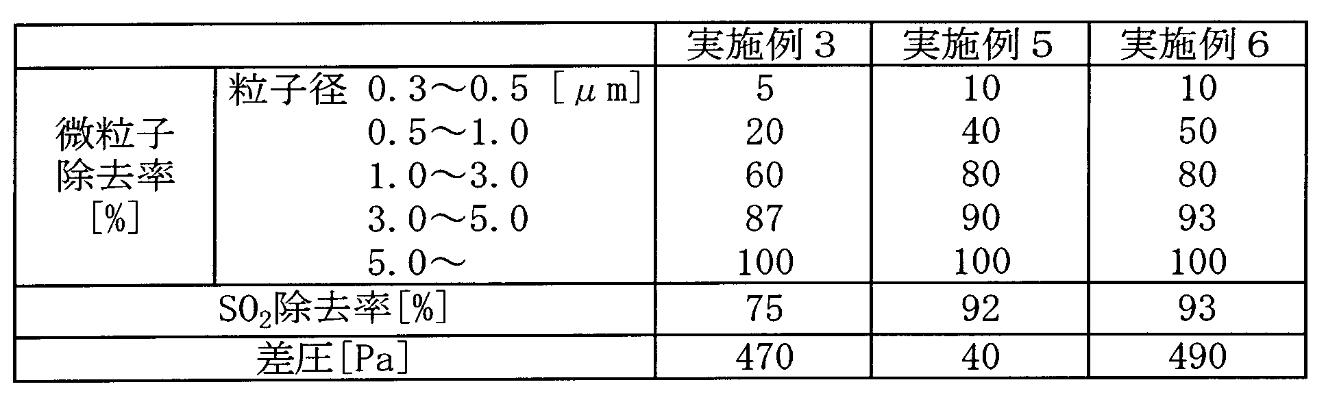
実施例5では、実施例3と比べて、粒子径5.0μm未満の微粒子除去率、SO2除去率、および差圧のいずれも大幅に向上していることが確認され、特に、差圧に関しては、約90%以上減少していることが確認された。実施例5の気液接触部は、積層体の中間層が実施例3の繊維集合体(高密度繊維集合体)に相当し、すなわち、高密度繊維集合体の上下を低密度繊維集合体で挟んだ構成を有している。したがって、実施例5において、気液接触部の厚みが厚くなっているにもかかわらず(実施例3:20mm、実施例5:120mm)、特に差圧に関して良好な結果が得られていることは、このような積層構造の効果であると考えられる。
一方で、実施例6では、実施例5の気液接触部に、微粒子除去性能が高い高密度繊維集合体を追加したことで、微粒子除去率に関しては、実施例5よりも良好な結果が得られているが、差圧には大幅な上昇が見られている。これは、実施例6では、積層体の最下層が高密度繊維集合体であり、下面での保水状態がさらに進行し、水封されたためであると考えられる。したがって、実施例5と実施例6とを比較すると、この差圧の点で、実施例5がより良好である。
1 空気浄化装置
2 筐体
3 吸気口
4 排気口
5 気液接触部
6 散水ノズル
7 循環タンク
8 循環ポンプ
9,13,14 配管
10 外部水源
11 給水弁
12 排水弁
15 エリミネータ
16 送風機
50 繊維集合体
50a 下面
50b 上面
51 積層体
52 上層(低密度繊維集合体)
53 中間層(高密度繊維集合体)
54 下層(低密度繊維集合体)
2 筐体
3 吸気口
4 排気口
5 気液接触部
6 散水ノズル
7 循環タンク
8 循環ポンプ
9,13,14 配管
10 外部水源
11 給水弁
12 排水弁
15 エリミネータ
16 送風機
50 繊維集合体
50a 下面
50b 上面
51 積層体
52 上層(低密度繊維集合体)
53 中間層(高密度繊維集合体)
54 下層(低密度繊維集合体)
Claims (7)
- 筐体に設けられた吸気口および排気口であって、前記排気口が前記吸気口の上方に位置する、吸気口および排気口と、
前記吸気口と前記排気口との間に設けられ、前記吸気口から前記筐体内に導入された空気が洗浄水に接触する気液接触部と、
前記気液接触部の上方に設けられ、前記気液接触部に前記洗浄水を散水する散水手段と、
前記洗浄水を貯留する洗浄水貯留手段と、
前記洗浄水貯留手段に貯留された前記洗浄水を前記散水手段に供給することで、前記洗浄水を循環させる洗浄水循環手段と、
を有し、
前記気液接触部が、厚み方向で繊維密度が異なるマット状の繊維集合体であって、該繊維集合体の一方の面が、低密度で起伏のある形状を有し、該繊維集合体の他方の面が、高密度で平坦な形状を有する、繊維集合体を有し、
前記繊維集合体は、前記一方の面が前記吸気口側に位置し、前記他方の面が前記排気口側に位置するように、前記吸気口と前記排気口との間に配置されている、空気浄化装置。 - 前記気液接触部は、平均繊維密度が異なる複数種類の前記繊維集合体が3層以上積層された積層体を有し、
前記積層体の最下層は、前記複数種類の繊維集合体のうち、平均繊維密度が最も低い前記繊維集合体で構成されている、請求項1に記載の空気浄化装置。 - 前記積層体の最上層は、前記最下層と同じ前記繊維集合体で構成されている、請求項2に記載の空気浄化装置。
- 前記積層体は、平均繊維密度が相対的に低い前記繊維集合体からなる上層と、平均繊維密度が相対的に高い前記繊維集合体からなる中間層と、平均繊維密度が相対的に低い前記繊維集合体からなる下層と、から構成されている、請求項3に記載の空気浄化装置。
- 前記吸気口から空気を導入して前記排気口から排出させる排気手段を有し、
前記排気手段は、前記気液接触部の上面を通過する空気流速が、前記気液接触部に散水される水滴の最小水滴径の自由落下速度以上となるように、前記吸気口から空気を導入するようになっている、請求項1から4のいずれか1項に記載の空気浄化装置。 - 前記散水手段の上方に設けられ、前記散水手段からの噴霧水の飛散を防止する防滴板を有し、
前記防滴板は、前記散水手段から散水された噴霧水が直接接触しない位置であって、前記吸気口から導入された空気により前記気液接触部の上面から巻き上げられた前記噴霧水が到達する位置に設置されている、請求項5に記載の空気浄化装置。 - 前記散水手段は、前記気液接触部を通過する空気の風量に対する、前記気液接触部への散水流量の比が0.5~3.0の範囲となるように、前記気液接触部に前記洗浄水を散水するようになっている、請求項1から6のいずれか1項に記載の空気浄化装置。
Priority Applications (2)
| Application Number | Priority Date | Filing Date | Title |
|---|---|---|---|
| CN201380023992.3A CN104284705B (zh) | 2012-05-08 | 2013-04-24 | 空气净化装置 |
| KR1020147021949A KR101596014B1 (ko) | 2012-05-08 | 2013-04-24 | 공기정화장치 |
Applications Claiming Priority (2)
| Application Number | Priority Date | Filing Date | Title |
|---|---|---|---|
| JP2012106706A JP5991849B2 (ja) | 2012-05-08 | 2012-05-08 | 空気浄化装置 |
| JP2012-106706 | 2012-05-08 |
Publications (1)
| Publication Number | Publication Date |
|---|---|
| WO2013168568A1 true WO2013168568A1 (ja) | 2013-11-14 |
Family
ID=49550619
Family Applications (1)
| Application Number | Title | Priority Date | Filing Date |
|---|---|---|---|
| PCT/JP2013/062046 Ceased WO2013168568A1 (ja) | 2012-05-08 | 2013-04-24 | 空気浄化装置 |
Country Status (5)
| Country | Link |
|---|---|
| JP (1) | JP5991849B2 (ja) |
| KR (1) | KR101596014B1 (ja) |
| CN (1) | CN104284705B (ja) |
| TW (2) | TWI660145B (ja) |
| WO (1) | WO2013168568A1 (ja) |
Cited By (4)
| Publication number | Priority date | Publication date | Assignee | Title |
|---|---|---|---|---|
| CN104676754A (zh) * | 2015-01-16 | 2015-06-03 | 葛荣超 | 液态空气净化器 |
| JP2017006868A (ja) * | 2015-06-24 | 2017-01-12 | オルガノ株式会社 | 空気浄化装置 |
| WO2021105635A1 (fr) * | 2019-11-28 | 2021-06-03 | Addup | Dispositif de filtration pour un dispositif de fabrication additive |
| WO2023002142A1 (fr) | 2021-07-23 | 2023-01-26 | Grtgaz | Séparateur gaz/condensats avec buse de nettoyage, et procédé de nettoyage correspondant |
Families Citing this family (21)
| Publication number | Priority date | Publication date | Assignee | Title |
|---|---|---|---|---|
| KR101478973B1 (ko) * | 2014-09-05 | 2015-01-05 | (주)효진엔지니어링 | 복수기능의 기액접촉수단을 이용한 산성 폐가스 처리 스크러버 |
| JP2016077945A (ja) * | 2014-10-14 | 2016-05-16 | アズビル株式会社 | ガス処理装置 |
| CN104913390B (zh) * | 2015-06-19 | 2019-06-14 | 广东佰宝电器有限公司 | 空气净化送风装置 |
| JP2017018855A (ja) * | 2015-07-07 | 2017-01-26 | オルガノ株式会社 | 空気浄化装置 |
| JP6681533B2 (ja) * | 2015-09-25 | 2020-04-15 | パナソニックIpマネジメント株式会社 | 空気浄化装置 |
| JP6670653B2 (ja) * | 2016-03-29 | 2020-03-25 | オルガノ株式会社 | 空気浄化装置 |
| SG11201910173YA (en) | 2017-05-11 | 2019-11-28 | Univ King Abdullah Sci & Tech | Device and method for microfluidics-based 3d bioprinting |
| CN107490056B (zh) * | 2017-08-18 | 2023-09-26 | 广东美的制冷设备有限公司 | 空气处理模块和空调器 |
| JP6427648B1 (ja) * | 2017-09-28 | 2018-11-21 | ニチアス株式会社 | 気液接触体 |
| CN108295592B (zh) * | 2018-03-23 | 2025-01-07 | 上海六滴智能科技有限公司 | 一种水空气净化器 |
| US11673324B2 (en) | 2020-08-20 | 2023-06-13 | King Abdullah University Of Science And Technology | Nozzle for 3D bioprinting |
| US12590121B2 (en) | 2020-08-20 | 2026-03-31 | King Abdullah University Of Science And Technology | Peptide compound with repetitive sequences |
| US12109327B2 (en) | 2020-08-20 | 2024-10-08 | King Abdullah University Of Science And Technology | Scaffolds from self-assembling tetrapeptides support 3D spreading, osteogenic differentiation and angiogenesis of mesenchymal stem cells |
| WO2022074574A1 (en) | 2020-10-06 | 2022-04-14 | King Adbullah University Of Science And Technology | Waste heat recovery system |
| KR102266049B1 (ko) | 2020-11-30 | 2021-06-16 | 고두수 | 기액접촉식 공기정화장치 |
| WO2022185263A1 (en) * | 2021-03-05 | 2022-09-09 | King Adbullah University Of Science And Technology | Wetted-wire liquid-gas contactor device |
| KR102556504B1 (ko) | 2021-09-03 | 2023-07-18 | 마이크로맥스 영농조합법인 | 무필터 방식의 실내 공기정화 및 살균장치 |
| KR102398311B1 (ko) * | 2021-11-08 | 2022-05-13 | 임규한 | 습식 집진기 |
| KR20230070971A (ko) | 2021-11-15 | 2023-05-23 | 삼성전자주식회사 | 공기 정화 장치 및 공기 정화 방법 |
| CN115155215B (zh) * | 2022-09-05 | 2022-11-11 | 泉州海关综合技术服务中心 | 一种纺织品阻燃测试用烟尘净化装置 |
| KR102624883B1 (ko) | 2023-07-31 | 2024-01-12 | 이승재 | 수처리식 공기정화 장치 |
Citations (6)
| Publication number | Priority date | Publication date | Assignee | Title |
|---|---|---|---|---|
| JPH08199461A (ja) * | 1995-01-13 | 1996-08-06 | San Chem Kk | 繊維シートの製造方法 |
| JPH08209514A (ja) * | 1995-02-07 | 1996-08-13 | Chisso Corp | 繊維成形体およびその製造法 |
| JPH08229341A (ja) * | 1995-02-23 | 1996-09-10 | Mitsui Mining Co Ltd | 気液接触方法及び装置 |
| JPH11197441A (ja) * | 1998-01-14 | 1999-07-27 | Sanwa:Kk | 排ガスの洗浄装置 |
| JP2005095859A (ja) * | 2003-09-03 | 2005-04-14 | Ryoji Hosokawa | 空気浄化装置 |
| JP2006081980A (ja) * | 2004-09-14 | 2006-03-30 | Isuzu Motors Ltd | ガス清浄装置 |
Family Cites Families (7)
| Publication number | Priority date | Publication date | Assignee | Title |
|---|---|---|---|---|
| JP4444389B2 (ja) | 1999-04-07 | 2010-03-31 | 住友電気工業株式会社 | 排ガスの浄化方法及び浄化装置 |
| ES2316408T3 (es) * | 2000-03-16 | 2009-04-16 | Kuraray Co., Ltd. | Fibras huecas y procedimiento de fabricacion de fibras huecas. |
| JP4117649B2 (ja) * | 2003-07-10 | 2008-07-16 | 中部電力株式会社 | 粗塵除去用濾材、及びその製造方法、並びにフィルタユニット |
| TWM253474U (en) * | 2003-07-23 | 2004-12-21 | Chiu Ting Machinery Co Ltd | Locking device for machine bed of wood planer |
| JP4878821B2 (ja) | 2005-11-29 | 2012-02-15 | 三洋電機株式会社 | 床置き式空気除菌装置 |
| JP5108682B2 (ja) * | 2008-08-22 | 2012-12-26 | オルガノ株式会社 | 空気浄化装置 |
| JP5645561B2 (ja) | 2010-09-09 | 2014-12-24 | オルガノ株式会社 | 空気浄化装置 |
-
2012
- 2012-05-08 JP JP2012106706A patent/JP5991849B2/ja not_active Expired - Fee Related
-
2013
- 2013-04-24 KR KR1020147021949A patent/KR101596014B1/ko not_active Expired - Fee Related
- 2013-04-24 WO PCT/JP2013/062046 patent/WO2013168568A1/ja not_active Ceased
- 2013-04-24 CN CN201380023992.3A patent/CN104284705B/zh not_active Expired - Fee Related
- 2013-04-30 TW TW106146194A patent/TWI660145B/zh not_active IP Right Cessation
- 2013-04-30 TW TW102115498A patent/TWI634934B/zh not_active IP Right Cessation
Patent Citations (6)
| Publication number | Priority date | Publication date | Assignee | Title |
|---|---|---|---|---|
| JPH08199461A (ja) * | 1995-01-13 | 1996-08-06 | San Chem Kk | 繊維シートの製造方法 |
| JPH08209514A (ja) * | 1995-02-07 | 1996-08-13 | Chisso Corp | 繊維成形体およびその製造法 |
| JPH08229341A (ja) * | 1995-02-23 | 1996-09-10 | Mitsui Mining Co Ltd | 気液接触方法及び装置 |
| JPH11197441A (ja) * | 1998-01-14 | 1999-07-27 | Sanwa:Kk | 排ガスの洗浄装置 |
| JP2005095859A (ja) * | 2003-09-03 | 2005-04-14 | Ryoji Hosokawa | 空気浄化装置 |
| JP2006081980A (ja) * | 2004-09-14 | 2006-03-30 | Isuzu Motors Ltd | ガス清浄装置 |
Cited By (7)
| Publication number | Priority date | Publication date | Assignee | Title |
|---|---|---|---|---|
| CN104676754A (zh) * | 2015-01-16 | 2015-06-03 | 葛荣超 | 液态空气净化器 |
| CN104676754B (zh) * | 2015-01-16 | 2015-12-30 | 葛荣超 | 液态空气净化器 |
| JP2017006868A (ja) * | 2015-06-24 | 2017-01-12 | オルガノ株式会社 | 空気浄化装置 |
| WO2021105635A1 (fr) * | 2019-11-28 | 2021-06-03 | Addup | Dispositif de filtration pour un dispositif de fabrication additive |
| FR3103712A1 (fr) * | 2019-11-28 | 2021-06-04 | Addup | Dispositif de filtration pour un dispositif de fabrication additive |
| WO2023002142A1 (fr) | 2021-07-23 | 2023-01-26 | Grtgaz | Séparateur gaz/condensats avec buse de nettoyage, et procédé de nettoyage correspondant |
| FR3125433A1 (fr) * | 2021-07-23 | 2023-01-27 | Grtgaz | Séparateur gaz/condensats avec buse de nettoyage, et procédé de nettoyage correspondant |
Also Published As
| Publication number | Publication date |
|---|---|
| TW201812223A (zh) | 2018-04-01 |
| CN104284705A (zh) | 2015-01-14 |
| JP5991849B2 (ja) | 2016-09-14 |
| CN104284705B (zh) | 2016-06-08 |
| KR101596014B1 (ko) | 2016-02-19 |
| TWI634934B (zh) | 2018-09-11 |
| TW201410309A (zh) | 2014-03-16 |
| JP2013233497A (ja) | 2013-11-21 |
| TWI660145B (zh) | 2019-05-21 |
| KR20140120328A (ko) | 2014-10-13 |
Similar Documents
| Publication | Publication Date | Title |
|---|---|---|
| JP5991849B2 (ja) | 空気浄化装置 | |
| JP3222973U (ja) | 湿式空気清浄器 | |
| JP5744223B2 (ja) | 湿式スクラバおよびプロセスガスを浄化する方法 | |
| JP6253701B2 (ja) | 空気浄化装置 | |
| KR101152015B1 (ko) | 팬을 이용한 습식 공기정화 장치 | |
| KR102121466B1 (ko) | 습식 공기청정기 | |
| CN101451755A (zh) | 室内空气净化加湿器 | |
| KR101898890B1 (ko) | 수평형 습식 스크러버용 클린 필터를 포함하는 조립체 및 그의 구성방법 | |
| JP6670653B2 (ja) | 空気浄化装置 | |
| CN106861318A (zh) | 一种空气净化装置及其净化方法 | |
| KR20180029939A (ko) | 습식 공기세척기 | |
| CN104587785B (zh) | 一种立式除尘器 | |
| CN202590564U (zh) | 水帘式喷漆/打磨净化设备 | |
| KR101726299B1 (ko) | 수평형 습식 스크러버용 클린 필터를 포함하는 조립체 및 그의 구성방법 | |
| JP6607712B2 (ja) | 空気浄化装置 | |
| CN219328173U (zh) | 一种液洗空气净化消毒器 | |
| CN220360929U (zh) | 一种除尘结构和除尘过滤结构 | |
| JP2017018855A (ja) | 空気浄化装置 | |
| JP6318716B2 (ja) | エアフィルターユニット | |
| CN209809835U (zh) | 一种新型卧式高效喷淋兼双层除雾废气净化塔 | |
| CN209952474U (zh) | 一种液洗空气净化器 | |
| CN105664624A (zh) | 一种空气净化装置 | |
| JP7418045B2 (ja) | 脱臭設備および脱臭方法 | |
| CN104722150A (zh) | 制药及化工行业用废气净化器 | |
| CN110841401B (zh) | 废气处理设备 |
Legal Events
| Date | Code | Title | Description |
|---|---|---|---|
| 121 | Ep: the epo has been informed by wipo that ep was designated in this application |
Ref document number: 13788045 Country of ref document: EP Kind code of ref document: A1 |
|
| ENP | Entry into the national phase |
Ref document number: 20147021949 Country of ref document: KR Kind code of ref document: A |
|
| NENP | Non-entry into the national phase |
Ref country code: DE |
|
| 122 | Ep: pct application non-entry in european phase |
Ref document number: 13788045 Country of ref document: EP Kind code of ref document: A1 |