WO2013168540A1 - 携帯端末 - Google Patents
携帯端末 Download PDFInfo
- Publication number
- WO2013168540A1 WO2013168540A1 PCT/JP2013/061634 JP2013061634W WO2013168540A1 WO 2013168540 A1 WO2013168540 A1 WO 2013168540A1 JP 2013061634 W JP2013061634 W JP 2013061634W WO 2013168540 A1 WO2013168540 A1 WO 2013168540A1
- Authority
- WO
- WIPO (PCT)
- Prior art keywords
- incoming call
- detection unit
- mobile terminal
- control unit
- unit
- Prior art date
- Legal status (The legal status is an assumption and is not a legal conclusion. Google has not performed a legal analysis and makes no representation as to the accuracy of the status listed.)
- Ceased
Links
Images


Classifications
-
- H—ELECTRICITY
- H04—ELECTRIC COMMUNICATION TECHNIQUE
- H04M—TELEPHONIC COMMUNICATION
- H04M1/00—Substation equipment, e.g. for use by subscribers
- H04M1/60—Substation equipment, e.g. for use by subscribers including speech amplifiers
- H04M1/6033—Substation equipment, e.g. for use by subscribers including speech amplifiers for providing handsfree use or a loudspeaker mode in telephone sets
- H04M1/6041—Portable telephones adapted for handsfree use
-
- H—ELECTRICITY
- H04—ELECTRIC COMMUNICATION TECHNIQUE
- H04M—TELEPHONIC COMMUNICATION
- H04M2250/00—Details of telephonic subscriber devices
- H04M2250/12—Details of telephonic subscriber devices including a sensor for measuring a physical value, e.g. temperature or motion
Definitions
- the present invention relates to a mobile terminal.
- the incoming call button When the mobile terminal receives an incoming call, the incoming call button is pressed to shift from the incoming call state to the call state. Therefore, the operator must press the incoming call button to make a call, and lacks responsiveness. In addition, in order to provide an incoming call button, it is necessary to secure an arrangement space thereof, which also hinders the miniaturization of the mobile terminal.
- Patent Documents 1 and 2 Various techniques related to such a background are known (see, for example, Patent Documents 1 and 2).
- Patent Document 1 describes a mobile phone device that automatically enters a response state when the user puts the earpiece of the mobile phone that is receiving a call signal on the ear. More specifically, this mobile phone device has a receiver that outputs an incoming call notification and a signal for a call as an audible sound from the earpiece to the outside. In addition, this mobile phone device senses the impedance change of the receiver accompanying the volume change of the space formed on the front surface of the receiver through the earpiece before and after placing on the ear, and outputs a detection signal indicating that the earpiece is placed on the ear Receiver impedance change detecting means.
- the mobile phone device includes a control unit that performs a response process to the call signal when receiving a detection signal from the receiver impedance change detection unit while outputting the incoming call tone based on the reception of the call signal from the receiver, and enables a call.
- a control unit that performs a response process to the call signal when receiving a detection signal from the receiver impedance change detection unit while outputting the incoming call tone based on the reception of the call signal from the receiver, and enables a call.
- the user can automatically shift to the response state by simply touching the earpiece of the mobile phone that is receiving the call signal without operating the response button or the like. The call can be started immediately.
- Patent Document 2 describes a mobile phone suitable for use in automatic off-hook / on-hook operation due to changes in the storage state. More specifically, this mobile phone is: ⁇ Operation unit for operating various arranged keys ⁇ Display unit for displaying various information to the user ⁇ Send / receive unit for sending and receiving audio to and from the user ⁇ Send received signals received from the antenna to the control unit In addition, it is connected to a transmission / reception unit / control unit that transmits transmission data output from the control unit from an antenna, and includes storage state detection means. It has an automatic call start / end mode for performing the operation.
- the cellular phone device described in Patent Document 1 cannot automatically shift to the response state when the ear is brought close to the earpiece and the ear is not applied.
- the objective of this invention is providing the portable terminal which solves the subject mentioned above.
- the present invention is provided in the vicinity of an earpiece that outputs the voice of the other party and an earpiece that emits the voice output from the earpiece, and an object approaches within a predetermined distance.
- a first detection unit for detecting the object and a position where the object is not detected in the state where the object is close to the first detection unit.
- the second detection unit detects an object and the incoming call is received
- the first detection unit detects an object, and if the second detection unit does not detect the object, the call state is changed to the call state.
- a portable terminal provided with a control unit that performs control.
- the present invention when there is an incoming call, it is possible to shift from the incoming call state to the call state simply by bringing the mobile terminal close to the ear. It can be simplified. At this time, depending on the present invention, even if the earpiece is not touched, it is sufficient that the earpiece is approached to some extent, and it is possible to shift from the incoming call state to the call state without forcing the user into an unreasonable posture. In addition, according to the present invention, if the mobile terminal is not brought close to the ear, it does not shift from the incoming call state to the call state, so whether the mobile phone is taken out of the clothes pocket or bag and the other party is confirmed before making a call. You can choose whether or not.
- FIG. 3 is a diagram illustrating an example of an appearance on the rear side of the mobile terminal 1.
- 2 is a diagram illustrating an example of a block configuration of a mobile terminal 1.
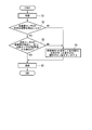
- FIG. It is a figure which shows an example of the operation
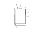
- FIG. 1 shows an example of the front side appearance of a portable terminal 1 according to an embodiment.
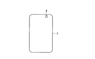
- FIG. 2 shows an example of the rear appearance of the mobile terminal 1.
- FIG. 3 shows an example of a block configuration of the mobile terminal 1.
- the mobile terminal 1 includes an acceleration sensor 2, proximity sensors 3 and 4, a receiver 5, a microphone 6, a vibrator 7, a display unit 8, a wireless unit 9, and a control unit 10.
- the acceleration sensor 2 may be an example of a “third detection unit” in the present invention.
- the proximity sensor 3 may be an example of a “first detection unit” in the present invention.
- the proximity sensor 4 may be an example of a “second detection unit” in the present invention.
- the receiver 5 may be an example of the “receiver” in the present invention.
- the vibrator 7 may be an example of the “vibrating part” in the present invention.
- the acceleration sensor 2 is a device that detects the attitude of the mobile terminal 1. More specifically, the acceleration sensor 2 is built in the mobile terminal 1. The acceleration sensor 2 is electrically connected to the control unit 10. When the acceleration sensor 2 detects the attitude of the mobile terminal 1, the acceleration sensor 2 outputs data indicating the attitude to the control unit 10.
- the proximity sensor 3 is a device that detects when an object approaches within a predetermined distance. More specifically, the proximity sensor 3 is provided in the vicinity of the earpiece that emits the sound output from the receiver 5. The proximity sensor 3 is electrically connected to the control unit 10. When the proximity sensor 3 detects that an object has approached within a predetermined distance, the proximity sensor 3 outputs data indicating that fact to the control unit 10.
- the proximity sensor 4 is a device that detects when an object approaches within a predetermined distance. More specifically, the proximity sensor 4 is provided at a position where the object is not detected when the object approaches the proximity sensor 3. In the present embodiment, the proximity sensor 4 is provided on the rear side of the mobile terminal 1. The proximity sensor 4 is electrically connected to the control unit 10. When the proximity sensor 4 detects that an object has approached within a predetermined distance, the proximity sensor 4 outputs data indicating that fact to the control unit 10.
- the receiver 5 is a device that outputs the voice of the other party. More specifically, the receiver 5 is mounted on the front side of the mobile terminal 1. The receiver 5 is electrically connected to the control unit 10. And the receiver 5 will change the electrical signal into a physical vibration and will output the other party's audio
- the microphone 6 is a device that receives an input of an operator's voice. More specifically, the microphone 6 is mounted on the front side of the mobile terminal 1. The microphone 6 is electrically connected to the control unit 10. When the microphone 6 receives the input of the operator's voice, the microphone 6 outputs an electrical signal indicating the voice to the control unit 10.
- the vibrator 7 is a device that vibrates when an incoming call is received. More specifically, the vibrator 7 is built in the mobile terminal 1. The vibrator 7 is electrically connected to the control unit 10. Vibrator 7 vibrates when it receives an input of an electric signal output from control unit 10.
- the display unit 8 is a device that displays characters and figures. More specifically, the display unit 8 is mounted on the front side of the mobile terminal 1. The display unit 8 is electrically connected to the control unit 10. And the display part 8 will display the character and figure shown by the data, if the input of the data output from the control part 10 is received.
- the wireless unit 9 is a device that transmits and receives wireless signals. More specifically, the wireless unit 9 is built in the mobile terminal 1. The wireless unit 9 is electrically connected to the antenna and the control unit 10. And the radio
- the control unit 10 is a device that controls the acceleration sensor 2, the proximity sensors 3 and 4, the receiver 5, the microphone 6, the vibrator 7, the display unit 8, and the wireless unit 9.
- FIG. 4 shows an example of an operation flow according to the first embodiment of the mobile terminal 1. In the description of this operation flow, both FIGS. 1 to 3 are referred to.
- the acceleration sensor 2 When there is an incoming call to the mobile terminal 1 (S1), the acceleration sensor 2 starts detecting the attitude of the mobile terminal 1. Then, the acceleration sensor 2 outputs data indicating the detected posture to the control unit 10.
- the control unit 10 determines whether or not the posture of the mobile phone 1 indicated by the data is a predetermined posture (S2).
- the predetermined posture can be, for example, a case where the mobile terminal 1 is in an upright state or a posture close thereto.
- the portable terminal 1 is in an upright state or a posture close to that when the operator tries to bring the hand close to the ear.
- the proximity sensor 3 will detect it. Then, the proximity sensor 3 outputs data indicating that an object has been detected to the control unit 10. Similarly, when the proximity sensor 4 detects an object, the proximity sensor 4 outputs data indicating that fact to the control unit 10.
- control unit 10 determines that the posture of the mobile phone 1 is the predetermined posture (S2: YES), the object is detected by the proximity sensor 3 and the object is not detected by the proximity sensor 4. (S3: YES), transition control is performed from the incoming call state to the call state (S5).
- control unit 10 receives an incoming call when the mobile terminal 1 is stored in a bag or a pocket (S1), and even if it is accidentally in a predetermined posture (S2: Yes) Since an object is detected by the sensor 3 and the proximity sensor 4 (S3: No), the transition control to the call state is not performed.
- the acceleration sensor 2 does not detect a change in the attitude of the mobile terminal 1, the automatic transition to the call (S5) is not performed.
- the operator operates the portable terminal 1 to display the incoming call button on the display unit 8 and touch the incoming call button unit (S4). This shifts to a call (S5).
- one step of pressing the incoming call button at the time of incoming call can be omitted, and the operability can be improved.
- the present invention can reduce the scale of the device and reduce the size and cost of the portable terminal.
- the present invention is characterized in that the operator automatically shifts to a call by bringing the receiver closer to the ear while the mobile terminal is informing the incoming call.
- the operator when a large volume is set as the ringtone of the mobile terminal, the operator will hear the ringtone close to the ear until the call is switched to the call, increasing the burden on the ear. there is a possibility.
- the following operation is added as the second embodiment.
- the acceleration sensor is used for detecting the attitude of the mobile terminal.
- the present invention is not limited to the acceleration sensor, and an electronic device having the same function may be used. Implementation is feasible.
- the proximity sensor can also implement the present invention as long as it can detect that the operator's face is approaching.
- the present invention when there is an incoming call, it is possible to shift from the incoming call state to the call state simply by bringing the mobile terminal close to the ear, so that the operation from the incoming call to the call can be simplified. At that time, it is possible to select whether or not to make a call without forcing the user into an unreasonable posture and taking out the mobile phone from the clothes pocket or bag and confirming the other party.
Landscapes
- Engineering & Computer Science (AREA)
- Signal Processing (AREA)
- Telephone Function (AREA)
Description
本発明は、携帯端末に関する。
携帯端末は、着信があると、着呼ボタンが押されることによって、着信状態から通話状態へ移行する。したがって、操作者は、通話するにあたり、着呼ボタンを押さなければならず、即応性に欠ける。また、着呼ボタンを設けるためには、その配置スペースを確保しなければならず、携帯端末の小型化への支障にもなる。
このような背景に関連する技術は、様々なものが知られている(例えば、特許文献1、2参照。)。
例えば、特許文献1には、呼出信号受信中の携帯電話機の受話口をユーザが耳に当てただけで自動的に応答状態となる携帯電話装置が記載されている。
より具体的に説明すると、この携帯電話装置は、着信通知、及び通話のための信号を可聴音として受話口から外部へ出力するレシーバを有する。
また、この携帯電話装置は、耳に当てる前後における受話口を通してレシーバ前面に形成される空間の容積変化に伴うレシーバのインピーダンス変化を感知して受話口を耳に当てたことを示す検出信号を出力するレシーバインピーダンス変化検出手段を有する。
また、この携帯電話装置は、呼出信号受信に基づく着信通話音をレシーバから出力中にレシーバインピーダンス変化検出手段からの検出信号を受信すると呼出信号に対する応答処理を行い、通話を可能とする制御手段を有する。
このようにして、この携帯電話装置によっては、ユーザは呼出信号受信中の携帯電話機の受話口に耳を当てるだけで自動的に応答状態に移行することができ、応答ボタン等を操作することなく直ちに通話を開始することができる。
より具体的に説明すると、この携帯電話装置は、着信通知、及び通話のための信号を可聴音として受話口から外部へ出力するレシーバを有する。
また、この携帯電話装置は、耳に当てる前後における受話口を通してレシーバ前面に形成される空間の容積変化に伴うレシーバのインピーダンス変化を感知して受話口を耳に当てたことを示す検出信号を出力するレシーバインピーダンス変化検出手段を有する。
また、この携帯電話装置は、呼出信号受信に基づく着信通話音をレシーバから出力中にレシーバインピーダンス変化検出手段からの検出信号を受信すると呼出信号に対する応答処理を行い、通話を可能とする制御手段を有する。
このようにして、この携帯電話装置によっては、ユーザは呼出信号受信中の携帯電話機の受話口に耳を当てるだけで自動的に応答状態に移行することができ、応答ボタン等を操作することなく直ちに通話を開始することができる。
また、特許文献2には、収納状態の変化によるオフフック/オンフックの自動操作に用いて好適な携帯電話機が記載されている。
より具体的に説明すると、この携帯電話機は:
・配列された各種キーの操作を行う操作部
・利用者への各種情報を表示する表示部
・利用者との間で音声を送受する送受話部
・アンテナから受信した受信信号を制御部に送出すると共に制御部から出力された送信データをアンテナから送信する送受信部
・制御部に接続して収納状態検知手段
を具備し、収納状態検知手段が検知した収納状態変化の信号によりオフフック、及びオンフックの操作を実施する自動通話開始/終了モードを有する。
このようにして、この携帯電話機によっては、収納場所に収納している状態で着信した場合、取り出すだけの操作でオフフックし、通話を終了する時には服の収納場所に収納する操作をすれば自動的にオンフックするので、操作性の簡潔化を図ることができる。
より具体的に説明すると、この携帯電話機は:
・配列された各種キーの操作を行う操作部
・利用者への各種情報を表示する表示部
・利用者との間で音声を送受する送受話部
・アンテナから受信した受信信号を制御部に送出すると共に制御部から出力された送信データをアンテナから送信する送受信部
・制御部に接続して収納状態検知手段
を具備し、収納状態検知手段が検知した収納状態変化の信号によりオフフック、及びオンフックの操作を実施する自動通話開始/終了モードを有する。
このようにして、この携帯電話機によっては、収納場所に収納している状態で着信した場合、取り出すだけの操作でオフフックし、通話を終了する時には服の収納場所に収納する操作をすれば自動的にオンフックするので、操作性の簡潔化を図ることができる。
しかしながら、特許文献1に記載の携帯電話装置は、受話口に耳を近付けただけで、耳を当てない場合、自動的に応答状態に移行することができない。
また、特許文献2に記載の携帯電話機は、服のポケットやバッグから取り出されただけで自動的にオンフックされてしまうので、利用者が通話する気のない場合にも、通話が開始されてしまう。
本発明の目的は、上述した課題を解決する携帯端末を提供することにある。
上記課題を解決するために、本発明は、通話相手の音声を出力する受話部と、受話部から出力される音声を放音する受話口の近傍に設けられて、所定距離内に物体が近づいた場合に、それを検知する第1の検知部と、第1の検知部に物体が近づいた状態において当該物体を検知しない位置に設けられて、所定距離内に物体が近づいた場合に、それを検知する第2の検知部と、着信があった場合に、第1の検知部が物体を検知して、第2の検知部が物体を検知していなければ、着信状態から通話状態へ移行するように制御する制御部とを備える携帯端末を提供する。
なお、上記の発明の概要は、本発明の特徴の全てを列挙したものではない。
また、これらの特徴群のサブコンビネーションもまた、発明となり得る。
以上の説明から明らかなように、この発明によっては、着信があった場合に、携帯端末を耳に近付けるだけで、着信状態から通話状態へ移行させることができるので、着信から通話までの操作を簡略化させることができる。その際、この発明によっては、受話口に耳が当たっていなくても、ある程度近づいていればよく、ユーザに対して無理な姿勢を強いることなく、着信状態から通話状態へ移行させることができる。また、この発明によっては、携帯端末を耳に近付けなければ、着信状態から通話状態へ移行しないので、携帯電話を服のポケットやバッグ等から取り出して、通話相手を確認してから、通話するか否かを選択することができる。
以下、発明の実施の形態を通じて本発明を説明するが、以下の実施形態は請求の範囲にかかる発明を限定するものではなく、また、実施形態の中で説明されている特徴の組み合わせの全てが発明の解決手段に必須であるとは限らない。
図1は、一実施形態に係る携帯端末1のフロント側の外観の一例を示す。図2は、携帯端末1のリア側の外観の一例を示す。図3は、携帯端末1のブロック構成の一例を示す。
携帯端末1は、加速度センサ2、近接センサ3、4、レシーバ5、マイク6、バイブ7、表示部8、無線部9、及び制御部10を備える。
なお、加速度センサ2は、この発明における「第3の検知部」の一例であってよい。また、近接センサ3は、この発明における「第1の検知部」の一例であってよい。また、近接センサ4は、この発明における「第2の検知部」の一例であってよい。また、レシーバ5は、この発明における「受話部」の一例であってよい。また、バイブ7は、この発明における「振動部」の一例であってよい。
加速度センサ2は、携帯端末1の姿勢を検出する装置である。より具体的に説明すると、加速度センサ2は、携帯端末1に内蔵されている。そして、加速度センサ2は、制御部10と電気的に接続されている。そして、加速度センサ2は、携帯端末1の姿勢を検出すると、その姿勢を示すデータを、制御部10へ出力する。
近接センサ3は、所定距離内に物体が近づいた場合に、それを検知する装置である。より具体的に説明すると、近接センサ3は、レシーバ5から出力される音声を放音する受話口の近傍に設けられている。そして、近接センサ3は、制御部10と電気的に接続されている。そして、近接センサ3は、所定距離内に物体が近づいたことを検知すると、その旨を示すデータを、制御部10へ出力する。
近接センサ4は、所定距離内に物体が近づいた場合に、それを検知する装置である。より具体的に説明すると、近接センサ4は、近接センサ3に物体が近づいた状態において、その物体を検知しない位置に設けられる。本実施形態においては、近接センサ4は、携帯端末1のリア側に設けられている。そして、近接センサ4は、制御部10と電気的に接続されている。そして、近接センサ4は、所定距離内に物体が近づいたことを検知すると、その旨を示すデータを、制御部10へ出力する。
レシーバ5は、通話相手の音声を出力する装置である。より具体的に説明すると、レシーバ5は、携帯端末1のフロント側に実装されている。そして、レシーバ5は、制御部10と電気的に接続されている。そして、レシーバ5は、制御部10から出力された、通話相手の音声を示す電気信号の入力を受け付けると、その電気信号を物理振動に変えて、通話相手の音声を出力する。
マイク6は、操作者の音声の入力を受け付ける装置である。より具体的に説明すると、マイク6は、携帯端末1のフロント側に実装されている。そして、マイク6は、制御部10と電気的に接続されている。そして、マイク6は、操作者の音声の入力を受け付けると、その音声を示す電気信号を、制御部10へ出力する。
バイブ7は、着信があった場合に振動する装置である。より具体的に説明すると、バイブ7は、携帯端末1に内蔵されている。そして、バイブ7は、制御部10と電気的に接続されている。そして、バイブ7は、制御部10から出力された電気信号の入力を受け付けると振動する。
表示部8は、文字や図形を表示する装置である。より具体的に説明すると、表示部8は、携帯端末1のフロント側に実装されている。そして、表示部8は、制御部10と電気的に接続されている。そして、表示部8は、制御部10から出力されたデータの入力を受け付けると、そのデータによって示される文字や図形を表示する。
無線部9は、無線信号の送受信を行う装置である。より具体的に説明すると、無線部9は、携帯端末1に内蔵されている。そして、無線部9は、アンテナ、及び制御部10と電気的に接続されている。そして、無線部9は、アンテナを介して無線信号を受信すると、その無線信号を電気信号に変換して、制御部10へ出力する。また、無線部9は、制御部10から出力された電気信号の入力を受け付けると、その電気信号を無線信号に変換して、アンテナを介して送信する。
制御部10は、加速度センサ2、近接センサ3、4、レシーバ5、マイク6、バイブ7、表示部8、及び無線部9を制御する装置である。
図4は、携帯端末1の第1の実施形態に係る動作フローの一例を示す。なおまた、この動作フローの説明においては、図1から図3を共に参照する。
携帯端末1に対して着信があると(S1)、加速度センサ2は、携帯端末1の姿勢の検出を開始する。そして、加速度センサ2は、検出した姿勢を示すデータを、制御部10へ出力する。
制御部10は、加速度センサ2から出力されたデータの入力を受け付けると、そのデータによって示される携帯電話1の姿勢が、所定姿勢であるか否かを判定する(S2)。ここで、所定姿勢とは、例えば、携帯端末1が直立状態か、それに近い姿勢である場合とすることができる。例えば、携帯端末1は、操作者が手にとって、耳に近付けようとするような場合に、直立状態か、それに近い姿勢となる。
そして、操作者が携帯端末1の所定距離内に耳を近づけると、近接センサ3は、それを検知する。そして、近接センサ3は、物体を検知したことを示すデータを、制御部10へ出力する。同様に、近接センサ4は、物体を検知すると、その旨を示すデータを、制御部10へ出力する。
制御部10は、携帯電話1の姿勢が所定姿勢であると判定している場合に(S2:YES)、近接センサ3により物体が検知されていて、近接センサ4により物体が検知されていなければ(S3:YES)、着信状態から通話状態へ移行制御する(S5)。
一方、制御部10は、携帯端末1が鞄の中やポケットの中等にしまわれているような場合に着信があり(S1)、偶然、所定姿勢にあったとしても(S2:Yes)、近接センサ3、及び近接センサ4により物体が検知されることになるので(S3:No)、通話状態へ移行制御しない。
また、加速度センサ2が携帯端末1の姿勢変化を検出しない場合も同様に通話(S5)への自動移行は行わない。
上記の通話への自動移行が行われない場合に着呼する場合は、操作者が携帯端末1を操作し、表示部8に着呼ボタンを表示させ、着呼ボタン部をタッチする(S4)ことで通話(S5)へ移行する。
以上、説明したように、本発明によって着信時に着呼ボタンを押す1ステップが省略可能となり操作性の向上を実現出来る。また、本発明によって装置規模を縮小し、携帯端末の小型化およびコストダウンを実現出来る。
本発明は、携帯端末の着信報知中に操作者がレシーバを耳元へ近づけることで、自動で通話へ移行することを特徴とする。ここで、携帯端末の着信音として大音量を設定している場合、着信から通話へ移行するまでの間、操作者が耳の間近で着信音を聞くことになり、耳への負担が大きくなる可能性がある。このような状況を防止するために、第2の実施形態として、以下の動作を追加する。
図5の様に携帯端末1に対して着信(S1)がある場合、操作者が携帯端末1を手で持ち上げて直立状態にし、加速度センサ2が携帯端末1の姿勢変化(所定の姿勢)を検出(S2)した後に、着信音量を低減する動作(S6)を追加する。
この動作を追加することによって、着信報知中の携帯端末1の着信音による操作者の耳への負担を軽減することが可能となり、操作性のさらなる向上を実現出来る。また、この動作はバイブの振動量についても同様の動作を行うものとする。
本発明のその他の実施例として、第1と第2の実施例では携帯端末の姿勢の検出に加速度センサを用いたが、加速度センサに限らず、同様の機能を持った電子デバイスでも本発明の実施を実現可能とする。
同様に、近接センサにおいても、操作者の顔が近づいたことを検出できる素子であれば本発明の実施を実現可能とする。
以上、本発明を実施の形態を用いて説明したが、本発明の技術的範囲は、上記実施の形態に記載の範囲には限定されない。上記実施の形態に、多様な変更、又は改良を加えることが可能であることが当業者に明らかである。そのような変更、又は改良を加えた形態も本発明の技術的範囲に含まれ得ることが、請求の範囲の記載から明らかである。
請求の範囲、明細書、及び図面中における動作、手順、ステップ、及び段階等の各処理の実行順序は、特段「より前に」、「先立って」等と明示していない。また、前の処理の出力を後の処理で用いるのでない限り、任意の順序で実現し得ることに留意すべきである。また、請求の範囲、明細書、及び図面中の動作フローに関して、便宜上「まず、」、「次に、」等を用いて説明したとしても、この順で実施することが必須であることを意味するものではない。
この出願は、2012年5月8日に出願された日本出願特願2012-106501号を基礎とする優先権を主張し、その開示の全てをここに取り込む。
この発明によっては、着信があった場合に、携帯端末を耳に近付けるだけで、着信状態から通話状態へ移行させることができるので、着信から通話までの操作を簡略化させることができる。その際、ユーザに対して無理な姿勢を強いることなく、また、携帯電話を服のポケットやバッグ等から取り出して、通話相手を確認してから、通話するか否かを選択することができる。
1 携帯端末
2 加速度センサ
3 近接センサ
4 近接センサ
5 レシーバ
6 マイク
7 バイブ
8 表示部
9 無線部
10 制御部
2 加速度センサ
3 近接センサ
4 近接センサ
5 レシーバ
6 マイク
7 バイブ
8 表示部
9 無線部
10 制御部
Claims (4)
- 通話相手の音声を出力する受話部と、
前記受話部から出力される音声を放音する受話口の近傍に設けられて、所定距離内に物体が近づいた場合に、それを検知する第1の検知部と、
前記第1の検知部に物体が近づいた状態において当該物体を検知しない位置に設けられて、所定距離内に物体が近づいた場合に、それを検知する第2の検知部と、
着信があった場合に、前記第1の検知部が物体を検知して、前記第2の検知部が物体を検知していなければ、着信状態から通話状態へ移行するように制御する制御部と
を備える携帯端末。 - 当該携帯端末の姿勢を検出する第3の検知部
を更に備え、
前記制御部は、着信があった場合に、前記第1の検知部が物体を検知して、前記第2の検知部が物体を検知しておらず、前記第3の検知部が検出した姿勢が所定姿勢であれば、着信状態から通話状態へ移行制御する
請求項1に記載の携帯端末。 - 前記受話部は、着信があった場合、着信状態から通話状態へ移行するまでの間、着信音を出力し、
前記制御部は、着信があった場合に、前記第3の検知部が検出した姿勢が所定姿勢であれば、前記着信音の音量を下げるべく制御する
請求項2に記載の携帯端末。 - 着信があった場合に振動する振動部
を更に備え、
前記制御部は、着信があった場合に、前記第3の検知部が検出した姿勢が所定姿勢であれば、前記振動部の振動量を下げるべく制御する
請求項2又は3に記載の携帯端末。
Applications Claiming Priority (2)
| Application Number | Priority Date | Filing Date | Title |
|---|---|---|---|
| JP2012106501A JP2013236201A (ja) | 2012-05-08 | 2012-05-08 | 携帯端末 |
| JP2012-106501 | 2012-05-08 |
Publications (1)
| Publication Number | Publication Date |
|---|---|
| WO2013168540A1 true WO2013168540A1 (ja) | 2013-11-14 |
Family
ID=49550591
Family Applications (1)
| Application Number | Title | Priority Date | Filing Date |
|---|---|---|---|
| PCT/JP2013/061634 Ceased WO2013168540A1 (ja) | 2012-05-08 | 2013-04-19 | 携帯端末 |
Country Status (2)
| Country | Link |
|---|---|
| JP (1) | JP2013236201A (ja) |
| WO (1) | WO2013168540A1 (ja) |
Families Citing this family (3)
| Publication number | Priority date | Publication date | Assignee | Title |
|---|---|---|---|---|
| CN103973544B (zh) | 2014-04-02 | 2017-10-24 | 小米科技有限责任公司 | 语音通话方法、语音播放方法及装置 |
| JP6397055B2 (ja) | 2015-01-16 | 2018-09-26 | 株式会社Nttドコモ | 通信端末装置、着信制御方法、及びプログラム |
| JP6688160B2 (ja) * | 2016-06-03 | 2020-04-28 | 株式会社Nttドコモ | 通信端末装置及びプログラム |
Citations (4)
| Publication number | Priority date | Publication date | Assignee | Title |
|---|---|---|---|---|
| JP2000152323A (ja) * | 1998-11-05 | 2000-05-30 | Sanyo Electric Co Ltd | 携帯通信端末の着信音制御装置及び着信音制御方法 |
| JP2000253131A (ja) * | 1999-03-01 | 2000-09-14 | Toshiba Corp | 音声通信装置 |
| JP2003198670A (ja) * | 2001-12-27 | 2003-07-11 | Yamaha Corp | 携帯電話装置及びその制御方法 |
| JP2011135551A (ja) * | 2009-11-27 | 2011-07-07 | Kyocera Corp | 携帯電子機器 |
-
2012
- 2012-05-08 JP JP2012106501A patent/JP2013236201A/ja not_active Abandoned
-
2013
- 2013-04-19 WO PCT/JP2013/061634 patent/WO2013168540A1/ja not_active Ceased
Patent Citations (4)
| Publication number | Priority date | Publication date | Assignee | Title |
|---|---|---|---|---|
| JP2000152323A (ja) * | 1998-11-05 | 2000-05-30 | Sanyo Electric Co Ltd | 携帯通信端末の着信音制御装置及び着信音制御方法 |
| JP2000253131A (ja) * | 1999-03-01 | 2000-09-14 | Toshiba Corp | 音声通信装置 |
| JP2003198670A (ja) * | 2001-12-27 | 2003-07-11 | Yamaha Corp | 携帯電話装置及びその制御方法 |
| JP2011135551A (ja) * | 2009-11-27 | 2011-07-07 | Kyocera Corp | 携帯電子機器 |
Also Published As
| Publication number | Publication date |
|---|---|
| JP2013236201A (ja) | 2013-11-21 |
Similar Documents
| Publication | Publication Date | Title |
|---|---|---|
| JP6257893B2 (ja) | 携帯端末装置、プログラムおよび携帯端末装置の制御方法 | |
| JP4982705B2 (ja) | アクセサリに関連するサウンド出力の選択 | |
| JP6278593B2 (ja) | 携帯端末装置、プログラムおよび表示制御方法 | |
| JP6043545B2 (ja) | 携帯端末装置、プログラムおよび携帯端末装置の制御方法 | |
| JP4056518B2 (ja) | 携帯情報端末、その表示制御方法およびプログラム | |
| JP4798218B2 (ja) | 通話装置 | |
| WO2014104040A1 (ja) | 携帯端末装置 | |
| JP6619132B2 (ja) | 携帯電子機器、制御方法、及び制御プログラム | |
| US20130260836A1 (en) | Mobile electronic device | |
| CN103227863A (zh) | 自动切换通话方向系统、方法及应用该系统的移动终端 | |
| CN101764884A (zh) | 一种移动终端翻转静音的方法和装置 | |
| CN107547975B (zh) | 音频通道的切换方法、系统和语音采集器 | |
| JP5494327B2 (ja) | 無線通信装置 | |
| JP2013074492A (ja) | 携帯電子機器 | |
| CN101600020A (zh) | 通信终端装置、信息处理装置 | |
| JP2013236201A (ja) | 携帯端末 | |
| JP5019330B2 (ja) | コードレス電話装置 | |
| JP2015106716A (ja) | 電子機器及び操作受付プログラム | |
| JP2013201494A (ja) | 携帯無線電話機、その制御方法、および、その制御プログラム | |
| JP5224992B2 (ja) | ハンズフリー機能付き携帯電話機 | |
| JP2002319997A (ja) | 携帯電話機 | |
| JP2013168715A (ja) | 携帯電話機 | |
| JP2013219566A (ja) | 携帯情報端末 | |
| JP2005217695A (ja) | 耳掛け式通話装置 | |
| JP3699009B2 (ja) | 携帯電話装置 |
Legal Events
| Date | Code | Title | Description |
|---|---|---|---|
| 121 | Ep: the epo has been informed by wipo that ep was designated in this application |
Ref document number: 13787343 Country of ref document: EP Kind code of ref document: A1 |
|
| NENP | Non-entry into the national phase |
Ref country code: DE |
|
| 122 | Ep: pct application non-entry in european phase |
Ref document number: 13787343 Country of ref document: EP Kind code of ref document: A1 |