WO2013161962A1 - 電気機器の取付構造 - Google Patents
電気機器の取付構造 Download PDFInfo
- Publication number
- WO2013161962A1 WO2013161962A1 PCT/JP2013/062286 JP2013062286W WO2013161962A1 WO 2013161962 A1 WO2013161962 A1 WO 2013161962A1 JP 2013062286 W JP2013062286 W JP 2013062286W WO 2013161962 A1 WO2013161962 A1 WO 2013161962A1
- Authority
- WO
- WIPO (PCT)
- Prior art keywords
- slide
- mounting
- protruding position
- slide portion
- attachment
- Prior art date
Links
Images


Classifications
-
- H—ELECTRICITY
- H02—GENERATION; CONVERSION OR DISTRIBUTION OF ELECTRIC POWER
- H02B—BOARDS, SUBSTATIONS OR SWITCHING ARRANGEMENTS FOR THE SUPPLY OR DISTRIBUTION OF ELECTRIC POWER
- H02B1/00—Frameworks, boards, panels, desks, casings; Details of substations or switching arrangements
- H02B1/015—Boards, panels, desks; Parts thereof or accessories therefor
- H02B1/04—Mounting thereon of switches or of other devices in general, the switch or device having, or being without, casing
- H02B1/042—Mounting on perforated supports by means of screws or locking members
-
- H—ELECTRICITY
- H02—GENERATION; CONVERSION OR DISTRIBUTION OF ELECTRIC POWER
- H02B—BOARDS, SUBSTATIONS OR SWITCHING ARRANGEMENTS FOR THE SUPPLY OR DISTRIBUTION OF ELECTRIC POWER
- H02B1/00—Frameworks, boards, panels, desks, casings; Details of substations or switching arrangements
- H02B1/015—Boards, panels, desks; Parts thereof or accessories therefor
- H02B1/04—Mounting thereon of switches or of other devices in general, the switch or device having, or being without, casing
- H02B1/052—Mounting on rails
- H02B1/0523—Mounting on rails locked into position by a sliding member
-
- H—ELECTRICITY
- H05—ELECTRIC TECHNIQUES NOT OTHERWISE PROVIDED FOR
- H05K—PRINTED CIRCUITS; CASINGS OR CONSTRUCTIONAL DETAILS OF ELECTRIC APPARATUS; MANUFACTURE OF ASSEMBLAGES OF ELECTRICAL COMPONENTS
- H05K7/00—Constructional details common to different types of electric apparatus
- H05K7/14—Mounting supporting structure in casing or on frame or rack
- H05K7/1462—Mounting supporting structure in casing or on frame or rack for programmable logic controllers [PLC] for automation or industrial process control
- H05K7/1474—Mounting of modules, e.g. on a base or rail or wall
Definitions
- the present invention relates to an electrical equipment mounting structure.
- electric devices such as a programmable controller (PLC), a relay, a timer, or a breaker are attached to a mounting surface such as a support rail or a wall surface.
- a mounting surface such as a support rail or a wall surface.
- a first fastener and a second fastener that are slidable in the same sliding direction are provided on the back surface of a base of an electronic device main body, and are connected to a support rail. Is attached to a position where the tip of the first fastener engages with the support rail.
- Each of the first and second fasteners has a screw hole, and when the screw hole is slid to a position protruding from the base, it is also locked at that position. Thereby, attachment to a support plate etc. is also attained.
- the first and second fasteners that are the slide portions are provided with arc-shaped elastic locking pieces that project so as to be cantilevered, and the base that is the mounting body
- the locking piece is locked in the locking hole formed on the back surface of the plate, and the slide portion is locked.
- the slide part may be unlocked by coming off the stop hole. Therefore, when the electric device is mounted on the mounting surface using the screw holes provided in the two slide portions (that is, in the case of direct mounting), when the slide portion is unlocked, the electric device is attached to the mounting body. At the same time, it may come off the mounting surface.
- the present invention is directed to an electric equipment mounting structure, and an object of the present invention is to firmly fix the slide portion to the mounting body in the case of direct mounting.
- the mounting structure for an electrical device includes a mounting body that supports or accommodates the electrical device, and a slide portion that is movable in a sliding direction along the bottom surface by a guide portion provided on the bottom surface of the mounting body.
- a slide portion that is movable in a sliding direction along the bottom surface by a guide portion provided on the bottom surface of the mounting body.
- the slide portion in the case of direct mounting on the mounting surface, can be firmly fixed to the mounting body.
- the electric device mounting structure further includes another slide portion that is movable in a sliding direction along the bottom surface by another guide portion provided on the bottom surface.
- One slide portion is formed on the bottom surface when the other slide portion is disposed at a through hole for inserting a mounting screw and the projecting position where the through hole is located outside the side surface of the mounting body.
- a state in which the other slide part is disposed at the projecting position and the attachment body is directly attached to the attachment surface.
- Both sides of the slide engagement portion in a direction perpendicular to the bottom surface are in direct or indirect contact with the protruding position locking portion and the mounting surface.
- the slide direction of the slide portion is different from the slide direction of the other slide portion.
- the electric device mounting structure is movable along the bottom surface and in a sliding direction different from the sliding direction by another guide portion provided on the bottom surface.
- a slide portion, and a rail engagement portion that is provided on the bottom surface and engages with one edge along the longitudinal direction of the support rail when the attachment main body is attached to a long support rail,
- the slide portion is arranged at the protruding position, and the through hole for inserting the mounting screw formed in the other slide portion is outside the side surface of the mounting body.
- the slide part and the other slide part One ride portion is disposed in the rail engaging position to the other edge engages along the longitudinal direction of the support rail.
- the slide part when the slide part is disposed at the projecting position, the slide part is engaged with another projecting position locking part having a convex shape or a concave shape formed on the bottom surface.
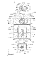
- FIG. 1 It is a perspective view which shows the attachment structure of an electric equipment. It is an exploded view of an attachment structure. It is a perspective view of an attachment structure. It is a bottom view of an attachment structure. It is sectional drawing of an attachment structure. It is a bottom view of an attachment structure. It is sectional drawing of an attachment structure. It is a bottom view of the attachment structure. It is sectional drawing of an attachment structure. It is a bottom view of the attachment structure of a comparative example. It is sectional drawing of the attachment structure of a comparative example. It is sectional drawing of the other example of an attachment structure.
- FIG. 1 is a perspective view showing a mounting structure 1 for an electric device 9 according to an embodiment of the present invention.
- the electrical device 9 is, for example, a programmable controller (PLC), a relay, a timer, or a breaker.
- the mounting structure 1 includes a box-shaped mounting body 2 in which an electrical device 9 is accommodated, and a first slide portion 3 is provided on one surface 21 (the ( ⁇ Y) side surface in FIG. 1) of the mounting body 2. And the 2nd slide part 4 is provided.
- the attachment main body 2, the first slide part 3, and the second slide part 4 are made of, for example, resin.
- the surface 21 When mounting the mounting structure 1 to a support rail or mounting surface, which will be described later, the surface 21 is often mounted so as to stand upright (of course, it may be mounted in another posture), but mounting before mounting. Since the structure 1 is often handled with the surface 21 facing downward in the vertical direction, the surface 21 of the mounting body 2 is referred to as a “bottom surface 21” in the following description.
- a bottom surface 21 In FIG. 1, two directions substantially along the bottom surface 21 and orthogonal to each other are shown as an X direction and a Z direction, and a direction substantially perpendicular to the bottom surface 21 is shown as a Y direction (the same applies hereinafter).
- the bottom surface 21 has a rectangular outer shape having sides parallel to the X direction and the Z direction.
- FIG. 2 is an exploded view of the mounting structure 1.
- the mounting body 2, the first slide portion 3, and the second slide portion 4 are separated and viewed from the ( ⁇ Y) side in FIG. 1 toward the (+ Y) direction. It shows the state.
- a groove 211 (hereinafter referred to as a “rail groove 211”) extending in the horizontal direction (X direction) in FIG.
- the support rail 81 has a rail groove. 211 is fitted.
- the first slide portion 3 and the second slide portion 4 are arranged on the ( ⁇ Z) side and the (+ Z) side of the rail groove 211, respectively. That is, the rail groove 211 is formed between the first slide portion 3 and the second slide portion 4.
- two rail engaging portions 22 projecting to the ( ⁇ Z) side are formed at the (+ Z) side edge of the rail groove 211.
- the two rail engaging portions 22 are arranged at both end portions of the rail groove 211 in the X direction.
- a groove 212 extending in the ( ⁇ Z) direction from the center of the rail groove 211 in the X direction (a groove used for movement of the first slide portion 3, hereinafter referred to as “slide groove 212”). ) Is formed. Further, a protrusion 231 protruding to the (+ X) side is formed at the ( ⁇ X) side edge of the slide groove 212, and a protrusion protruding to the ( ⁇ X) side at the (+ X) side edge of the slide groove 212. A portion 231 is formed.
- both end portions 310 in the X direction are thinner than other portions, and both end portions 310 are bottom surfaces of the slide grooves 212 (surfaces perpendicular to the Y direction).
- the protrusions 231 (see FIG. 1).
- the first guide portion 23 including the two protrusion portions 231 extends along the bottom surface 21 of the mounting body 2 and the slide groove 212 extends (that is, the Z direction, hereinafter referred to as “first slide direction”). .) Is supported so as to be movable.
- the ( ⁇ Y) side surface of the first slide portion 3 supported by the first guide portion 23 is substantially flush with the area of the bottom surface 21 excluding grooves 211 and 212 and a later-described recess 213. To position.
- a portion 311 that slightly protrudes to the (+ Y) side is formed in the vicinity of both end portions 310 of the first slide portion 3 shown in FIG. 2, and two portions for sliding the portion 311 on the bottom surface of the slide groove 212 are formed.
- An auxiliary groove 251 is formed. Between the two auxiliary grooves 251, two other auxiliary grooves 252 that are used when the first slide portion 3 is attached to the attachment body 2 are formed, and each auxiliary groove 252 has 2 on the ( ⁇ Z) side. Two grooves 253 and 254 are formed side by side in the Z direction.
- the main body 31 of the first slide part 3 has an opening 32 at the center, and the outer shape of the opening 32 is substantially rectangular.
- a long member 33 protruding to the (+ X) side is formed at the ( ⁇ X) side edge of the opening 32, and the tip of the long member 33 is disposed in the vicinity of the (+ X) side edge of the opening 32.
- a long member 33 protruding to the ( ⁇ X) side is formed at the (+ X) side edge of the opening 32, and the tip of the long member 33 is near the ( ⁇ X) side edge of the opening 32. Be placed.
- the leaf spring-like two long members 33 extending in the X direction and supported in a cantilever state are formed in the opening 32 of the first slide portion 3 side by side in the Z direction.
- the A slide engagement portion 34 is formed in the vicinity of the free end of each long member 33, and the slide engagement portion 34 slightly protrudes to the (+ Y) side from the main body 31 and the long member 33.
- the first slide portion 3 When the first slide portion 3 is attached to the attachment body 2, the first slide portion 3 is disposed on the (+ Z) side of the first guide portion 23 as shown by a two-dot chain line in FIG.
- both end portions 310 By moving the slide portion 3 in the ( ⁇ Z) direction, both end portions 310 are inserted between the bottom surface of the slide groove 212 and both the protrusion portions 231.
- the part 311 of each end 310 slides in the auxiliary groove 251, and each slide engagement part 34 slides in the auxiliary groove 252.
- the slide engaging portion 34 reaches the end on the ( ⁇ Z) side of the auxiliary groove 252, the first slide portion 3 is pushed in the ( ⁇ Z) direction, so that each slide engaging portion 34 enters the groove 253.
- the first slide portion 3 is disposed at the position shown in FIG. 1 (hereinafter referred to as “rail engagement position”). At the rail engagement position, most of the first slide portion 3 overlaps the bottom surface 21 in the Y direction.
- the groove 253 shown in FIG. 2 is referred to as an “engagement position locking portion 253”.
- first slide portion 3 is disposed at the position shown in FIG. 3 (hereinafter referred to as “first protruding position”).
- first protruding position a through hole 39 (hereinafter referred to as “first through hole 39”) formed at the ( ⁇ Z) side end of the first slide portion 3 is on the ( ⁇ Z) side of the mounting body 2.
- first through hole 39 Located on the outside of the side surface.
- the first through hole 39 is a hole for inserting a mounting screw, which will be described later.
- the groove 254 shown in FIG. 2 is referred to as a “projection position locking portion 254”.
- the concave portion 213 is formed on the (+ Z) side of the rail groove 211 on the bottom surface 21 of the mounting body 2, and the second guide portion 24 is provided in the concave portion 213.
- the second guide portion 24 includes a substantially annular main body 241 formed on the bottom surface (a surface perpendicular to the Y direction) of the recess 213.
- a central axis 240 of the main body 241 parallel to the Y direction is disposed on a central line C1 parallel to the Z direction on the bottom surface 21.
- two thin plate-like projections 242 projecting toward the central axis 240 are formed, and the two projections 242 are formed on the (+ Z) side of the central axis 240 and ( -Z) arranged on the side.
- the second slide part 4 has a substantially disc-shaped main body 41 and a main body protruding part 45 continuous to the main body 41, and a central hole 411 is formed at the center of the main body 41.
- a cylindrical portion 42 is formed around the center hole 411 on the (+ Y) side surface of the main body 41, and (+ X) direction and ( ⁇ X) direction are provided at the (+ Y) side end of the cylindrical portion 42.
- Two protruding thin plate-like projections 43 are formed. When viewed along the Y direction, the two protrusions 43 have an arc shape along the outer edge of the cylindrical portion 42.
- the opening formed by the inner edge of the main body 241 and the edges of the two arc-shaped projecting portions 242 along the inner edge is formed in the outer shape of the cylindrical portion 42 and the two projecting portions 43. It is a copied shape. Therefore, the two protruding portions 43 and the cylindrical portion 42 can be inserted into the main body 241 of the second guide portion 24 through the opening.
- a part of the second slide portion 4 in a state in which the two protruding portions 43 and the cylindrical portion 42 are inserted into the second guide portion 24 is indicated by a two-dot chain line.
- the second slide portion 4 can rotate counterclockwise around the central axis 240 from the position of the two-dot chain line in FIG. 2, and when the second slide portion 4 is rotated, the second slide portion 4 A part of the protrusion 43 is disposed on the (+ Y) side of the protrusion 242 of the second guide part 24.
- the second slide portion 4 is supported by the second guide portion 24 so as to be movable (rotatable) in a rotation direction (hereinafter referred to as “second slide direction”) around the central axis 240.
- second slide direction a rotation direction
- the ( ⁇ Y) side surface of the second slide portion 4 supported by the second guide portion 24 is located on substantially the same plane as the region of the bottom surface 21 excluding the grooves 211 and 212 and the recess 213. .
- the slide engaging portion 44 is configured by the portion and the portion of the main body 41 that substantially overlaps the portion in the Y direction. That is, the vicinity of the tip of an arc-shaped portion 412 described later is the slide engagement portion 44.
- the second slide portion 4 has two slide engagement portions 44, and the two slide engagement portions 44 are arranged at positions that are point-symmetric with respect to the center (center hole 411) of the main body 41.
- the second slide portion 4 in FIG. 2 in which the protrusion 43 and the cylindrical portion 42 are inserted into the second guide portion 24.
- the two grooves 261 in which the two slide engaging portions 44 of the second slide portion 4) indicated by a two-dot chain line are disposed are formed (in FIG. 2, only one groove is denoted by reference numeral 261). The same applies to the groove 262 described later).
- a groove 263, a groove 262, and a groove 264 are sequentially formed adjacent to each groove 261 in the counterclockwise direction of FIG. 2 centering on the central axis 240.
- the groove 262 is shallower than the other grooves 261, 263, and 264.
- each slide engagement portion 44 (more precisely, the (+ Y) side portion of the slide engagement portion 44) is disposed in the groove 261.
- the slide engagement portion 44 is disposed in the groove 263 and the both engage with each other.
- the movement of the two slide portions 4 is locked (that is, the position of the second slide portion 4 is locked).
- the second slide portion 4 is arranged at the position shown in FIG. 1 (hereinafter referred to as “retreat position”). In the retracted position, the entire second slide portion 4 overlaps the bottom surface 21 in the Y direction.
- the groove 263 shown in FIG. 2 is referred to as a “retracted position locking portion 263”.
- two arc-shaped portions 412 are formed along the circumferential direction around the center hole 411, and each portion 412 is supported by the main body 41 in a cantilever state.
- the slide engagement portion 44 is formed at the tip (free end) of the plate spring-like portion 412, and when the slide engagement portion 44 moves from the groove 261 to the groove 263, the portion 412 bends.
- each slide engagement portion 44 slides in the relatively shallow groove 262 and reaches the end of the groove 262.
- the slide engagement portion 44 is disposed in the groove 264 and engaged with each other, and the movement of the second slide portion 4 is locked. .
- the second slide portion 4 is disposed at the position shown in FIG. 3 (hereinafter referred to as “second protruding position”).
- the groove 264 shown in FIG. 2 is referred to as a “projection position locking portion 264”.
- a through hole 49 (hereinafter referred to as “second through hole 49”) formed in the main body projecting portion 45 of the second slide portion 4 is outside the side surface on the (+ Z) side of the mounting main body 2. Located in. The 2nd through-hole 49 is a hole for the below-mentioned attachment screw insertion.
- FIG. 4 is a bottom view of the mounting structure 1 and shows a state in which the first slide portion 3 and the second slide portion 4 are arranged at the rail engaging position and the retracted position, respectively.
- FIG. 5 is a cross-sectional view at the position of the arrow VV in FIG. 4, and shows only the vicinity of the first slide portion 3 and the bottom surface 21 of the mounting body 2. In FIG. 5, each member is shown with the thickness in the Y direction larger than the actual thickness (the same applies to FIG. 7 described later).
- the first slide portion 3 When the attachment body 2 is attached to the support rail 81, the first slide portion 3 is disposed at the rail engagement position. And while the other edge 812 of the support rail 81 is sandwiched between the rail engaging portion 22 and the bottom surface of the rail groove 211 (surface perpendicular to the Y direction), the other edge 812 of the support rail 81 is The first slide portion 3 is pressed against the end portion 35 on the (+ Z) side. As shown in FIG. 5, the ( ⁇ Y) side surface of the end portion 35 of the first slide portion 3 has an inclined surface 351 in which the thickness of the main body 31 gradually decreases in the (+ Z) direction. Is formed. Further, as described above, the slide engaging portion 34 locked in the engaging position locking portion 253 shown in FIG.
- the first slide portion 3 When the edge 812 of the support rail 81 passes through the (+ Z) side of the end portion 35 of the first slide portion 3 and reaches the bottom surface of the rail groove 211, the first slide portion 3 is returned to the original position (the long member). 33 is a position that is not deformed and returns to the position shown in FIG. 4, and the edge 812 of the support rail 81 is sandwiched between the end portion 35 of the first slide portion 3 and the bottom surface of the rail groove 211. The That is, the first slide portion 3 engages with the edge 812 of the support rail 81 at the rail engagement position.
- the 2nd slide part 4 is not utilized by the attachment to the support rail 81 of the attachment main body 2, the 2nd slide part 4 is arrange
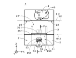
- FIG. 6 is a bottom view of the mounting structure 1 and shows a state in which the first slide portion 3 and the second slide portion 4 are arranged at the first protruding position and the second protruding position, respectively.
- FIG. 7 is a cross-sectional view at the position of arrows VII-VII in FIG. 6 and shows only the vicinity of the first slide portion 3 and the bottom surface 21 of the mounting body 2.
- the attachment main body 2 When the attachment main body 2 is directly attached to the attachment surface, the first slide portion 3 is pulled out to the first protruding position, and the second slide portion 4 is pulled out to the second protruding position. As a result, the first through hole 39 of the first slide part 3 and the second through hole 49 of the second slide part 4 are positioned outside the side surface of the mounting body 2. And the attachment main body 2 is directly attached to an attachment surface by inserting an attachment screw in each through-hole 39, 49 and fastening the said screw to an attachment surface. At this time, as shown in FIG.
- a plate-like auxiliary protrusion 243 is formed on the (+ Z) side portion of the main body 241 of the second guide portion 24, and the main body protrusion 45 of the second slide portion 4.
- FIG. 8 is a bottom view showing a mounting structure 90 of a comparative example
- FIG. 9 is a cross-sectional view at the position of arrows IX-IX in FIG.
- both the first slide portion 91 and the second slide portion 92 are movable in the same slide direction (Z direction in FIG. 8).
- the attachment main body 93 is attached to the support rail 81
- the first slide portion 91 and the second slide portion 92 are disposed at the positions indicated by the two-dot chain line in FIG. 811 respectively.
- the attachment main body 93 is directly attached to the attachment surface
- the first slide portion 91 and the second slide portion 92 are arranged at the positions indicated by solid lines in FIG.
- the attachment main body 93 is attached to the attachment surface 80.
- an engagement portion 912 provided at the tip of a member supported in a cantilever state has an engagement hole formed in the bottom surface of the mounting body 93.
- the first slide portion 91 is fixed (locked) to the mounting body 93 by engaging with 932.
- the second slide portion 92 is also fixed to the mounting body 93 by the same mechanism.
- the slide in the direction perpendicular to the bottom surface 21 of the mounting body 2 in the state where the first slide portion 3 is disposed at the first protruding position and the mounting body 2 is directly mounted on the mounting surface 80.
- Both sides of the engaging portion 34 abut against the protruding position locking portion 254 and the mounting surface 80, respectively.
- the slide engagement portion 34 is prevented from being detached from the protruding position locking portion 254, and the first slide portion 3 is firmly fixed to the attachment body 2. be able to.
- both sides of the slide engaging portion 44 in the direction perpendicular to the bottom surface 21 of the mounting body 2 are The second slide portion 4 can be firmly fixed to the mounting body 2 by coming into contact with the protruding position locking portion 264 and the mounting surface 80, respectively.
- the first slide portion 3 has a plurality of slide engagement portions 34 that abut against the protruding position locking portion 254 and the attachment surface 80, respectively. Can be more firmly fixed to the mounting body 2. Further, since the second slide portion 4 has a plurality of slide engagement portions 44 that respectively contact the protruding position locking portion 264 and the attachment surface 80, the second slide portion 4 is stronger than the attachment main body 2. Can be fixed to.
- the first slide direction in the first slide part 3 and the second slide direction in the second slide part 4 are different.
- the first slide is temporarily assumed during the direct mounting. Even when the lock is released in both the part 3 and the second slide part 4, it is possible to prevent the mounting body 2 from moving greatly in either direction.
- the first guide portion 23 and the second guide portion 24 prevent the attachment main body 2 directly attached to the attachment surface 80 from moving greatly in either direction, so that sliding engagement is possible. It is possible to more reliably prevent the engagement between the portions 34 and 44 and the protruding position locking portions 254 and 264 from being released.
- the second slide direction in the second slide portion 4 is a rotation direction around the central axis 240 perpendicular to the bottom surface 21 of the mounting body 2, the second slide portion 4 is disposed at the second protruding position.
- a member that resists the force in the Y direction to the part in the above example, the engagement groove 451 of the second slide part 4 is provided.
- the auxiliary protrusion 243) of the second guide portion 24 can be easily provided.
- the first slide direction and the second slide direction may be various directions along the bottom surface 21 of the mounting body 2.
- the first slide direction in the first slide portion 3 is centered on an axis perpendicular to the bottom surface 21.
- the rotation direction may be used.
- the first slide portion 3 is provided with a portion that protrudes toward the rail groove 211 in a state of being arranged at the rail engagement position, and the support rail 81 is attached when the attachment body 2 is attached to the support rail 81.
- the portion engages with the edge 812 of the.
- the first guide portion 23 and the second guide portion 24 provided on the bottom surface 21 of the mounting body 2 can employ various structures other than those described above.
- the concave engagement position locking portion 253, the protruding position locking portions 254 and 264, and the retreat position locking portion 263 are formed on the bottom surface 21 of the mounting body 2, and the slide engagement having a convex portion.
- the joint portions 34 and 44 engage with these locking portions, but the engagement position locking portion 253, the protruding position locking portions 254 and 264, and the retracted position locking portion 263 are convex on the bottom surface 21 of the mounting body 2.
- the slide engaging portions 34 and 44 having concave portions may be engaged with these locking portions. Further, in the engaging portion 912 of the comparative example, as shown in FIG.
- a portion 99 protruding to the ( ⁇ Y) side is added, and one end of the engaging portion 912 (slide engaging portion) in the Y direction is a locking hole.
- the slide portion may be firmly fixed to the attachment main body.
- the part that abuts on the locking hole 932 and the part that abuts on the attachment surface 80 may be arranged at positions slightly shifted in the direction along the bottom surface of the attachment main body.
- the portion 99 may be provided as a separate member from the engaging portion 912 and the mounting surface 80.
- the engaging portion 912 is indirectly contacted with the mounting surface 80 via an independent member. Touch.
- both sides of the slide engagement part are locked to the protruding position. It is important to abut directly or indirectly on the part and the mounting surface.
- the ( ⁇ X) side engaging position locking portion 253 and the (+ X) side protruding position locking portion 254 of FIG. 2 are omitted, and the first slide portion 3 is disposed at the rail engaging position. Only one slide engagement portion 34 is engaged with the engagement position locking portion 253, and when the first slide portion 3 is disposed at the first protruding position, only the other slide engagement portion 34 is locked at the protruding position locking.
- the portion 254 may be engaged. That is, the slide engaging portion 34 that locks the first slide portion 3 at the rail engaging position and the first protruding position may be different members.
- the mounting body 2 when the mounting body 2 is directly mounted on the mounting surface 80, the first slide portion 3 and the second slide portion 4 are locked at the first protruding position and the second protruding position.
- the mounting body 2 In the mounting structure 1 in which the first slide direction and the second slide direction are different, even if one or both of the first slide portion 3 and the second slide portion 4 are not locked in direct mounting, the mounting body 2 is either It is possible to prevent the mounting body 2 from being largely moved in the direction, that is, to fix the mounting body 2 against an external force in any direction.
- the second slide portion 4 does not contribute to the mounting of the mounting body 2 to the support rail 81, and therefore the position of the second sliding portion 4 when mounting the mounting body 2 to the support rail 81 is It may be arbitrarily determined. Further, the second slide portion 4 is provided with a portion that protrudes toward the rail groove 211 in a state of being disposed at the retracted position, and one edge of the support rail 81 is attached when the attachment body 2 is attached to the support rail 81. The part may engage with 811. In this case, the rail engaging portion 22 of FIG. 1 provided on the bottom surface 21 of the mounting body 2 can be omitted. In other words, the rail engaging portion that engages with one edge 811 of the support rail 81 when the attachment main body 2 is attached to the support rail 81 may be realized by the second slide portion 4 disposed at the retracted position. .
- the second slide portion 4 may be omitted, and for example, a part having a through hole may be formed in advance on the side surface of the mounting body 2 on the (+ Z) side.
- the second slide portion 4 is provided that can entirely overlap the bottom surface 21 of the mounting body 2. It is preferable.
- the mounting body 2 in the mounting structure 1 may be, for example, a member that supports the electrical device 9 by fixing one surface of the electrical device 9 in addition to housing the electrical device 9 therein.
Abstract
電気機器の取付構造(1)は、電気機器が収容される取付本体(2)と、取付本体(2)の底面(21)に設けられる案内部により底面(21)に沿うスライド方向に移動可能であるスライド部(3)とを備える。スライド部(3)は、取付ねじ挿入用の貫通孔(39)と、貫通孔(39)が取付本体(2)の側面よりも外側に位置する突出位置にスライド部(3)が配置される場合に、底面(21)に形成された凹状の突出位置係止部(254)と係合するスライド係合部(34)とを備える。スライド部(3)が突出位置に配置されて取付本体(2)が取付面に直接取り付けられた状態において、底面(21)に垂直な方向におけるスライド係合部(34)の両側が突出位置係止部(254)と取付面とに当接する。これにより、スライド部(3)が取付本体(2)に対して強固に固定される。
Description
本発明は、電気機器の取付構造に関する。
従来より、プログラマブルコントローラ(PLC)や、リレー、タイマー、あるいは、ブレーカー等の電気機器を支持レールや壁面等の取付面に取り付けることが行われている。例えば、特開2003-298252号公報(文献1)では、電子機器本体の基台の背面において、同じスライド方向にスライド自在な第1の留め具および第2の留め具が設けられ、支持レールへの取付の際に、第1の留め具の先端が支持レールに係合する位置にロックされる。第1および第2の留め具のそれぞれはねじ孔を有し、ねじ孔が基台から突出する位置にスライドされたとき、その位置でもロックされる。これにより、支持板等への取付も可能となる。
ところで、文献1の取付構造において、スライド部である第1および第2の留め具では、片持ち支持するように突設された円弧状の弾性係止片が設けられ、取付本体である基台の背面に形成された係止孔に当該係止片が係止されてスライド部がロックされるが、このようなロック機構では、電気機器に対して大きな外力が作用すると、係止片が係止孔から外れてスライド部のロックが解除されてしまう虞がある。したがって、2つのスライド部に設けられるねじ孔を利用して電気機器を取付面に取り付けた場合に(すなわち、直接取付の場合に)、スライド部のロックが解除されると、電気機器が取付本体と共に取付面から外れる可能性がある。
本発明は電気機器の取付構造に向けられており、直接取付の場合に、スライド部を取付本体に対して強固に固定することを目的としている。
本発明に係る電気機器の取付構造は、電気機器が支持または収容される取付本体と、前記取付本体の底面に設けられる案内部により前記底面に沿うスライド方向に移動可能であるスライド部とを備え、前記スライド部が、取付ねじ挿入用の貫通孔と、前記貫通孔が前記取付本体の側面よりも外側に位置する突出位置に前記スライド部が配置される場合に、前記底面に形成された凸状または凹状の突出位置係止部と係合するスライド係合部とを備え、前記スライド部が前記突出位置に配置されて前記取付本体が取付面に直接取り付けられた状態において、前記底面に垂直な方向における前記スライド係合部の両側が前記突出位置係止部と前記取付面とに直接的または間接的に当接する。
本発明によれば、取付面への直接取付の場合に、スライド部を取付本体に対して強固に固定することができる。
本発明の一の好ましい形態では、電気機器の取付構造が、前記底面に設けられるもう1つの案内部により前記底面に沿うスライド方向に移動可能であるもう1つのスライド部をさらに備え、前記もう1つのスライド部が、取付ねじ挿入用の貫通孔と、前記貫通孔が前記取付本体の側面よりも外側に位置する突出位置に前記もう1つのスライド部が配置される場合に、前記底面に形成された凸状または凹状の突出位置係止部と係合するスライド係合部とを備え、前記もう1つのスライド部が前記突出位置に配置されて前記取付本体が前記取付面に直接取り付けられた状態において、前記底面に垂直な方向における前記スライド係合部の両側が前記突出位置係止部と前記取付面とに直接的または間接的に当接する。これにより、直接取付の場合に、もう1つのスライド部を取付本体に対して強固に固定することができる。
この場合に、前記スライド部の前記スライド方向と、前記もう1つのスライド部の前記スライド方向とが相違することが好ましい。
本発明の他の好ましい形態では、電気機器の取付構造が、前記底面に設けられるもう1つの案内部により前記底面に沿い、かつ、前記スライド方向と相違するスライド方向に移動可能であるもう1つのスライド部と、前記底面に設けられ、前記取付本体が長尺の支持レールに取り付けられる際に、前記支持レールの長手方向に沿う一方の縁と係合するレール係合部とをさらに備え、前記取付本体が前記取付面に直接取り付けられる場合に、前記突出位置に前記スライド部が配置され、前記もう1つのスライド部に形成された取付ねじ挿入用の貫通孔が前記取付本体の側面よりも外側に位置する突出位置に前記もう1つのスライド部が配置され、前記取付本体が前記支持レールに取り付けられる場合に、前記スライド部および前記もう1つのスライド部の一方が前記支持レールの前記長手方向に沿う他方の縁と係合するレール係合位置に配置される。その結果、2つのスライド部の移動により、取付面への直接取付、および、支持レールへの取付が可能な取付構造において、直接取付の場合に、取付本体がいずれかの方向に大きく移動することを防止することができる。
本発明のさらに他の好ましい形態では、前記スライド部が、前記突出位置に前記スライド部が配置される場合に、前記底面に形成された凸状または凹状のもう1つの突出位置係止部と係合するもう1つのスライド係合部をさらに備え、前記スライド部が前記突出位置に配置されて前記取付本体が前記取付面に直接取り付けられた状態において、前記底面に垂直な方向における前記もう1つのスライド係合部の両側が前記もう1つの突出位置係止部と前記取付面とに直接的または間接的に当接する。これにより、スライド部を取付本体に対してより強固に固定することができる。
上述の目的および他の目的、特徴、態様および利点は、添付した図面を参照して以下に行うこの発明の詳細な説明により明らかにされる。
図1は本発明の一の実施の形態に係る電気機器9の取付構造1を示す斜視図である。電気機器9は、例えばプログラマブルコントローラ(PLC)や、リレー、タイマー、あるいは、ブレーカー等である。取付構造1は、電気機器9が収容される箱状の取付本体2を備え、取付本体2の一の面21(図1中の(-Y)側の面)には、第1スライド部3および第2スライド部4が設けられる。取付本体2、第1スライド部3および第2スライド部4は、例えば樹脂にて形成される。取付構造1の後述の支持レールや取付面への取付では、当該面21が直立するように取り付けられることが多いが(もちろん、他の姿勢にて取り付けられてもよい。)、取付前の取付構造1は、当該面21を鉛直方向の下方に向けて取り扱われることが多いため、以下の説明では、取付本体2の面21を「底面21」と呼ぶ。図1では、底面21におよそ沿うとともに互いに直交する2方向をX方向およびZ方向として示し、底面21におよそ垂直な方向をY方向として示している(以下同様)。図1の取付構造1では、底面21は、X方向およびZ方向に平行な辺を有する矩形の外形を有する。
図2は、取付構造1の分解図であり、取付本体2、第1スライド部3および第2スライド部4を分離して、図1の(-Y)側から(+Y)方向を向いて見た様子を示している。取付本体2の底面21には、図2の横方向(X方向)に伸びる溝211(以下、「レール溝211」という。)が形成される。後述するように、取付本体2が長尺の支持レール81(例えば、DINレールであり、図2中にて二点鎖線にて示す。)に取り付けられる際には、当該支持レール81はレール溝211内に嵌め込まれる。図1に示すように、第1スライド部3および第2スライド部4は、レール溝211の(-Z)側および(+Z)側にそれぞれ配置される。すなわち、レール溝211は、第1スライド部3と第2スライド部4との間に形成される。
図2に示すように、レール溝211の(+Z)側の縁には(-Z)側に突出する2つのレール係合部22が形成される。当該2つのレール係合部22は、X方向におけるレール溝211の両端部に配置され、取付本体2の支持レール81への取付の際には、レール係合部22とレール溝211の底面(Y方向に垂直な面)との間にて支持レール81の長手方向に沿う一方の縁811が挟持される。すなわち、レール係合部22は、支持レール81の一方の縁811と係合する。
取付本体2の底面21には、X方向におけるレール溝211の中央から(-Z)方向に伸びる溝212(第1スライド部3の移動に用いる溝であり、以下、「スライド溝212」という。)が形成される。また、スライド溝212の(-X)側の縁には(+X)側に突出する突起部231が形成され、スライド溝212の(+X)側の縁には(-X)側に突出する突起部231が形成される。第1スライド部3における矩形の薄板状の本体31では、X方向における両端部310が他の部位よりも薄くなっており、両端部310は、スライド溝212の底面(Y方向に垂直な面)と両突起部231との間にて挟持される(図1参照)。このように、2つの突起部231を含む第1案内部23により、取付本体2の底面21に沿うとともにスライド溝212が伸びる方向(すなわち、Z方向であり、以下、「第1スライド方向」という。)に第1スライド部3が移動可能に支持される。なお、第1案内部23にて支持された状態の第1スライド部3の(-Y)側の面は、底面21における溝211,212および後述の凹部213を除く領域とほぼ同一平面上に位置する。
図2に示す第1スライド部3の両端部310近傍には、(+Y)側に僅かに突出した部位311が形成され、スライド溝212の底面には、部位311が摺動するための2つの補助溝251が形成される。2つの補助溝251の間には、第1スライド部3を取付本体2に取り付ける際に利用される他の2つの補助溝252が形成され、各補助溝252の(-Z)側には2つの溝253,254がZ方向に並んで形成される。
第1スライド部3の本体31はおよそ中央に開口32を有し、開口32の外形は略矩形である。開口32の(-X)側の縁には(+X)側に突出する長尺部材33が形成され、当該長尺部材33の先端は開口32の(+X)側の縁の近傍に配置される。また、開口32の(+X)側の縁には(-X)側に突出する長尺部材33が形成され、当該長尺部材33の先端は開口32の(-X)側の縁の近傍に配置される。このように、第1スライド部3の開口32には、X方向におよそ沿って伸びるとともに、片持ち状態にて支持される板バネ状の2つの長尺部材33がZ方向に並んで形成される。各長尺部材33の自由端近傍にはスライド係合部34が形成され、スライド係合部34は本体31および長尺部材33よりも(+Y)側に僅かに突出する。
第1スライド部3を取付本体2に取り付ける際には、図2中にて二点鎖線にて示すように第1案内部23の(+Z)側に第1スライド部3が配置され、第1スライド部3を(-Z)方向に移動することにより、両端部310がスライド溝212の底面と両突起部231との間に挿入される。このとき、各端部310の部位311は補助溝251内を摺動し、各スライド係合部34は補助溝252内を摺動する。スライド係合部34が補助溝252の(-Z)側の端部まで到達すると、第1スライド部3が(-Z)方向に押し込まれることにより、各スライド係合部34が溝253内に配置されて両者が係合し、第1スライド部3の移動が係止される(すなわち、第1スライド部3の位置がロックされる。)。これにより、第1スライド部3が図1に示す位置(以下、「レール係合位置」という。)に配置される。レール係合位置では、第1スライド部3の大部分がY方向において底面21と重なる。以下の説明では、図2に示す溝253を「係合位置係止部253」という。
また、第1スライド部3が(-Z)方向にさらに押し込まれると、各スライド係合部34が溝254内に配置されて両者が係合し、第1スライド部3の移動が係止される。これにより、第1スライド部3が図3に示す位置(以下、「第1突出位置」という。)に配置される。第1突出位置では、第1スライド部3の(-Z)側の端部に形成された貫通孔39(以下、「第1貫通孔39」という。)が取付本体2の(-Z)側の側面よりも外側に位置する。第1貫通孔39は後述の取付ねじ挿入用の孔である。以下の説明では、図2に示す溝254を「突出位置係止部254」という。
取付本体2の底面21においてレール溝211の(+Z)側には、凹部213が形成され、凹部213内には第2案内部24が設けられる。詳細には、第2案内部24は、凹部213の底面(Y方向に垂直な面)に形成される略円環状の本体241を有する。Y方向に平行な本体241の中心軸240は、底面21におけるZ方向に平行な中心線C1上に配置される。本体241の(-Y)側の端部には、中心軸240に向かって突出する薄板状の2つの突起部242が形成され、2つの突起部242は中心軸240の(+Z)側および(-Z)側に配置される。
第2スライド部4は、略円板状の本体41、および、本体41に連続する本体突出部45を有し、本体41の中央には中心孔411が形成される。本体41の(+Y)側の面上において、中心孔411の周囲には円筒部42が形成され、円筒部42の(+Y)側の端部には(+X)方向および(-X)方向に突出する薄板状の2つの突起部43が形成される。Y方向に沿って見た場合において、2つの突起部43は円筒部42の外縁に沿う円弧状である。また、第2案内部24において、本体241の内縁、および、当該内縁に沿う円弧状の2つの突起部242の縁により形成される開口は、上記円筒部42および2つの突起部43の外形に倣った形状である。したがって、当該2つの突起部43および円筒部42は当該開口を介して第2案内部24の本体241の内部に挿入可能である。図2では、2つの突起部43および円筒部42を第2案内部24内に挿入した状態の第2スライド部4の一部を二点鎖線にて示している。
また、第2スライド部4は、図2の二点鎖線の位置から中心軸240を中心として反時計回りに回転可能であり、第2スライド部4を回転した状態では、第2スライド部4の突起部43の一部が、第2案内部24の突起部242の(+Y)側に配置される。このように、第2スライド部4は、中心軸240を中心とする回転方向(以下、「第2スライド方向」という。)に移動可能(回転可能)に第2案内部24により支持される。なお、第2案内部24にて支持された状態の第2スライド部4の(-Y)側の面は、底面21における溝211,212および凹部213を除く領域とほぼ同一平面上に位置する。
第2スライド部4の本体41の(+Y)側の面において外縁近傍(後述する円弧状の部位412の先端近傍)には、(+Y)側に僅かに突出した部位(図2中にて細い破線にて示す部位)が形成され、当該部位および当該部位とY方向におよそ重なる本体41の部位によりスライド係合部44が構成される。すなわち、後述の円弧状の部位412の先端近傍がスライド係合部44である。第2スライド部4は、2つのスライド係合部44を有し、2つのスライド係合部44は本体41の中心(中心孔411)に対して互いに点対称となる位置に配置される。また、第2案内部24の本体241において(-Y)側の面上には、突起部43および円筒部42を第2案内部24内に挿入した状態の第2スライド部4(図2中にて二点鎖線にて示す第2スライド部4)の2つのスライド係合部44が配置される2つの溝261が形成される(図2では、1つの溝のみに符号261を付している。後述の溝262において同様。)。本体241の当該面上には、中心軸240を中心とする図2の反時計回りにおいて、各溝261に隣接して溝263、溝262および溝264が順に形成される。なお、溝262は、他の溝261,263,264よりも浅い。
第2スライド部4を取付本体2に取り付ける際には、既述のように第2スライド部4の突起部43および円筒部42が第2案内部24内に挿入される。このとき、各スライド係合部44(正確には、スライド係合部44の(+Y)側の部位)が溝261内に配置される。そして、第2スライド部4を中心軸240を中心として図2の反時計回りに僅かな角度だけ回転させることにより、スライド係合部44が溝263内に配置されて両者が係合し、第2スライド部4の移動が係止される(すなわち、第2スライド部4の位置がロックされる。)。これにより、第2スライド部4が図1に示す位置(以下、「後退位置」という。)に配置される。後退位置では、第2スライド部4の全体がY方向において底面21と重なる。以下の説明では、図2に示す溝263を「後退位置係止部263」という。
第2スライド部4の本体41では、中心孔411を中心とする周方向に沿う円弧状の2つの部位412が形成されており、各部位412は片持ち状態にて本体41に支持される。スライド係合部44は、板バネ状の当該部位412の先端(自由端)に形成され、スライド係合部44が溝261から溝263へと移動する際には、当該部位412が撓むことにより、比較的小さい力にて第2スライド部4を移動(回動)することが可能である(後述する溝263から溝262を介する溝264への移動において同様)。
また、第2スライド部4を反時計回りにさらに回転させると、各スライド係合部44が、比較的浅い溝262内を摺動し、溝262の端部まで到達する。第2スライド部4を反時計回りに僅かな角度だけさらに回転させると、スライド係合部44が溝264内に配置されて両者が係合し、第2スライド部4の移動が係止される。これにより、第2スライド部4が図3に示す位置(以下、「第2突出位置」という。)に配置される。以下の説明では、図2に示す溝264を「突出位置係止部264」という。第2突出位置では、第2スライド部4の本体突出部45に形成された貫通孔49(以下、「第2貫通孔49」という。)が取付本体2の(+Z)側の側面よりも外側に位置する。第2貫通孔49は後述の取付ねじ挿入用の孔である。
図4は、取付構造1の底面図であり、第1スライド部3および第2スライド部4をそれぞれレール係合位置および後退位置に配置した状態を示している。図5は、図4中の矢印V-Vの位置における断面図であり、第1スライド部3および取付本体2の底面21近傍のみを示している。なお、図5では、Y方向の厚さを実際よりも大きくして各部材を図示している(後述の図7において同様)。
取付本体2が支持レール81に取り付けられる際には、第1スライド部3がレール係合位置に配置される。そして、支持レール81の長手方向に沿う一方の縁811をレール係合部22とレール溝211の底面(Y方向に垂直な面)との間に挟みつつ、支持レール81の他方の縁812が第1スライド部3の(+Z)側の端部35に押し当てられる。図5に示すように、第1スライド部3の当該端部35において(-Y)側の面には、(+Z)方向に向かうに従って本体31のY方向の厚さが漸次減少する傾斜面351が形成される。また、既述のように、図4に示す係合位置係止部253内にて係止されたスライド係合部34は、X方向に長い長尺部材33の自由端近傍に設けられる。したがって、支持レール81の縁812を傾斜面351に当てて(+Y)方向に押し込むに従って、長尺部材33が弾性変形しつつ、第1スライド部3の本体31が支持レール81の長手方向に垂直な第1スライド方向(正確には、(-Z)方向)に移動する。
そして、支持レール81の縁812が第1スライド部3の端部35の(+Z)側を通過し、レール溝211の底面へと到達すると、第1スライド部3が元の位置(長尺部材33が変形していない位置であり、図4中に示す位置)へと戻り、支持レール81の縁812が第1スライド部3の端部35とレール溝211の底面との間にて挟持される。すなわち、レール係合位置において、第1スライド部3が支持レール81の縁812と係合する。なお、取付本体2の支持レール81への取付では、第2スライド部4は利用されないため、第2貫通孔49が底面21上に位置する後退位置に第2スライド部4が配置され、第2スライド部4の全体が底面21と重なる。したがって、取付本体2の支持レール81への取付の際に、第2スライド部4が取付作業や他の部材の配置の邪魔になることはない。
図6は、取付構造1の底面図であり、第1スライド部3および第2スライド部4をそれぞれ第1突出位置および第2突出位置に配置した状態を示している。図7は、図6中の矢印VII-VIIの位置における断面図であり、第1スライド部3および取付本体2の底面21近傍のみを示している。
取付本体2が取付面に直接取り付けられる際には、第1スライド部3が第1突出位置へと引き出され、第2スライド部4が第2突出位置へと引き出される。これにより、第1スライド部3の第1貫通孔39および第2スライド部4の第2貫通孔49が取付本体2の側面よりも外側に位置する。そして、各貫通孔39,49に取付ねじを挿入して当該ねじを取付面に締結することにより、取付本体2が取付面に直接取り付けられる。このとき、図7に示すように、底面21に垂直なY方向における各スライド係合部34の両側が突出位置係止部254と取付面80とに当接する、すなわち、スライド係合部34が突出位置係止部254と取付面80とに挟まれる。これにより、第1スライド部3が取付本体2に対して強固に固定される。同様に、図6の第2スライド部4において、Y方向におけるスライド係合部44の両側が突出位置係止部264と取付面80とに当接することにより、第2スライド部4が取付本体2に対して強固に固定される。
また、図1および図2に示すように、第2案内部24の本体241の(+Z)側の部位には板状の補助突起部243が形成され、第2スライド部4の本体突出部45は、第2突出位置に配置された際に、補助突起部243が挿入されるように形成された係合溝451を有する。したがって、第2スライド部4が第2突出位置(図3に示す位置)に配置された状態において、仮に、本体突出部45に対して取付本体2の底面21に垂直な方向の力が作用した場合でも、係合溝451の内面と第2案内部24の補助突起部243(図1参照)とが当接することにより、第2スライド部4の移動を支持する突起部43および第2案内部24の突起部242(図2参照)が破損することが防止される。
図8は、比較例の取付構造90を示す底面図であり、図9は、図8中の矢印IX-IXの位置における断面図である。比較例の取付構造90では、第1スライド部91および第2スライド部92が共に同じスライド方向(図8中のZ方向)に移動可能である。取付本体93が支持レール81に取り付けられる場合には、第1スライド部91および第2スライド部92が図8中に二点鎖線にて示す位置に配置され、支持レール81の双方の縁812,811とそれぞれ係合する。また、取付本体93が取付面に直接取り付けられる場合には、第1スライド部91および第2スライド部92が図8中に実線にて示す位置に配置され、貫通孔911,921を利用して取付本体93が取付面80に取り付けられる。この場合に、第1スライド部91では、図9に示すように、片持ち状態にて支持される部材の先端に設けられる係合部912が、取付本体93の底面に形成された係止孔932に係合して第1スライド部91が取付本体93に対して固定(ロック)される。また、第2スライド部92も同様の機構にて取付本体93に対して固定される。
しかしながら、図9のロック機構では、取付面80と係合部912との間に比較的大きな隙間があるため、取付本体93に対して大きな外力が作用した場合に、図9中に二点鎖線にて示すように、係合部912が係止孔932から外れて第1スライド部91のロックが解除されてしまう虞がある(第2スライド部92において同様)。第1スライド部91および第2スライド部92の双方においてロックが解除されると、取付本体93がスライド方向(Z方向)に大きく移動してしまう。
これに対し、取付構造1では、第1スライド部3が第1突出位置に配置されて取付本体2が取付面80に直接取り付けられた状態において、取付本体2の底面21に垂直な方向におけるスライド係合部34の両側が突出位置係止部254と取付面80とにそれぞれ当接する。これにより、取付面80への直接取付の場合に、スライド係合部34が突出位置係止部254から外れることを防止して、第1スライド部3を取付本体2に対して強固に固定することができる。また、第2スライド部4が第2突出位置に配置されて取付本体2が取付面80に直接取り付けられた状態において、取付本体2の底面21に垂直な方向におけるスライド係合部44の両側が突出位置係止部264と取付面80とにそれぞれ当接することにより、第2スライド部4を取付本体2に対して強固に固定することができる。
取付面80への直接取付の場合に、それぞれが突出位置係止部254と取付面80とに当接する複数のスライド係合部34を第1スライド部3が有することにより、第1スライド部3を取付本体2に対してより強固に固定することができる。また、それぞれが突出位置係止部264と取付面80とに当接する複数のスライド係合部44を第2スライド部4が有することにより、第2スライド部4を取付本体2に対してより強固に固定することができる。
取付構造1では、第1スライド部3における第1スライド方向と、第2スライド部4における第2スライド方向とが相違する。これにより、2つのスライド部3,4の移動により、取付面80への直接取付、および、支持レール81への取付が選択可能な取付構造1において、直接取付の際に、仮に、第1スライド部3および第2スライド部4の双方においてロックが解除された場合でも、取付本体2がいずれかの方向に大きく移動することを防止することができる。換言すると、取付構造1では、取付面80に直接取り付けられた取付本体2がいずれかの方向に大きく移動することが第1案内部23および第2案内部24により防止されるため、スライド係合部34,44と突出位置係止部254,264との係合が解除されることをより確実に防止することができる。
また、第2スライド部4における第2スライド方向が、取付本体2の底面21に垂直な中心軸240を中心とする回転方向であることにより、第2スライド部4が第2突出位置に配置された状態において、取付本体2の側面から突出した第2スライド部4の部位近傍に、当該部位へのY方向の力に抵抗する部材(上記の例では、第2スライド部4の係合溝451および第2案内部24の補助突起部243)を設けることが容易に可能となる。
以上、本発明の実施の形態について説明してきたが、本発明は上記実施の形態に限定されるものではなく、様々な変形が可能である。
第1スライド方向および第2スライド方向は、取付本体2の底面21に沿う様々な方向であってよく、例えば、第1スライド部3における第1スライド方向が底面21に垂直な軸を中心とする回転方向とされてもよい。この場合、第1スライド部3において、レール係合位置に配置された状態にてレール溝211側に突出する部位が設けられ、取付本体2の支持レール81への取付の際に、支持レール81の縁812に当該部位が係合する。また、取付本体2の底面21に設けられる第1案内部23および第2案内部24は、上記以外の様々な構造を採用することが可能である。
上記実施の形態では、取付本体2の底面21に凹状の係合位置係止部253、突出位置係止部254,264、後退位置係止部263が形成され、凸状の部位を有するスライド係合部34,44がこれらの係止部と係合するが、取付本体2の底面21に凸状の係合位置係止部253、突出位置係止部254,264、後退位置係止部263が形成され、凹状の部位を有するスライド係合部34,44がこれらの係止部と係合してもよい。また、比較例の係合部912において、図10に示すように(-Y)側に突出する部位99が付加され、Y方向における係合部912(スライド係合部)の一端が係止孔932に(直接的に)当接した状態で、係合部912の他端である当該部位99が取付面80に当接することにより、スライド部が取付本体に対して強固に固定されてもよい。この場合に、係止孔932に当接する部位と、取付面80に当接する部位とが、取付本体の底面に沿う方向に僅かにずれた位置に配置されてもよい。また、部位99が、係合部912や取付面80とは別部材として設けられてもよく、この場合、独立した部材を介して、係合部912が取付面80に対して間接的に当接する。以上のように、取付面80への直接取付の場合に、第1スライド部および第2スライド部を取付本体に対して強固に固定するには、スライド係合部の両側が、突出位置係止部と取付面とに直接的または間接的に当接することが重要である。
例えば、図2の(-X)側の係合位置係止部253および(+X)側の突出位置係止部254が省略され、第1スライド部3がレール係合位置に配置される際に一方のスライド係合部34のみが係合位置係止部253と係合し、第1スライド部3が第1突出位置に配置される際に他方のスライド係合部34のみが突出位置係止部254と係合してもよい。すなわち、第1スライド部3をレール係合位置および第1突出位置にてロックするスライド係合部34は、異なる部材であってもよい。
図1の取付構造1では、取付本体2の取付面80への直接取付の場合に、第1スライド部3および第2スライド部4が第1突出位置および第2突出位置にてロックされるが、第1スライド方向と第2スライド方向とが相違する取付構造1では、直接取付において第1スライド部3および第2スライド部4の一方または双方がロックされない場合でも、取付本体2がいずれかの方向に大きく移動することを防止する、すなわち、あらゆる方向の外力に対して取付本体2を固定することが可能である。
図1の取付構造1では、第2スライド部4は取付本体2の支持レール81への取付に寄与しないため、取付本体2の支持レール81への取付の際における第2スライド部4の位置は任意に決定されてよい。また、第2スライド部4において、後退位置に配置された状態にてレール溝211側に突出する部位を設け、取付本体2の支持レール81への取付の際に、支持レール81の一方の縁811に当該部位が係合してもよい。この場合、取付本体2の底面21に設けられる図1のレール係合部22は省略可能である。換言すると、取付本体2が支持レール81に取り付けられる際に支持レール81の一方の縁811と係合するレール係合部は、後退位置に配置される第2スライド部4により実現されてもよい。
取付構造1において第2スライド部4が省略され、例えば取付本体2の(+Z)側の側面に、貫通孔を有する部位が予め形成されてもよい。ただし、取付構造1の支持レール81への取付の際における取付構造1の占有面積を小さくするという観点では、全体が取付本体2の底面21と重なることが可能な第2スライド部4が設けられることが好ましい。
取付構造1における取付本体2は、電気機器9を内部に収容するもの以外に、例えば、電気機器9の一の面が固定されて電気機器9を支持する部材であってもよい。
上記実施の形態および各変形例における構成は、相互に矛盾しない限り適宜組み合わされてよい。
発明を詳細に描写して説明したが、既述の説明は例示的であって限定的なものではない。したがって、本発明の範囲を逸脱しない限り、多数の変形や態様が可能であるといえる。
1 取付構造
2 取付本体
3 第1スライド部
4 第2スライド部
9 電気機器
21 底面
23 第1案内部
24 第2案内部
34,44 スライド係合部
39 第1貫通孔
49 第2貫通孔
80 取付面
254,264 突出位置係止部
2 取付本体
3 第1スライド部
4 第2スライド部
9 電気機器
21 底面
23 第1案内部
24 第2案内部
34,44 スライド係合部
39 第1貫通孔
49 第2貫通孔
80 取付面
254,264 突出位置係止部
Claims (6)
- 電気機器の取付構造であって、
電気機器が支持または収容される取付本体と、
前記取付本体の底面に設けられる案内部により前記底面に沿うスライド方向に移動可能であるスライド部と、
を備え、
前記スライド部が、
取付ねじ挿入用の貫通孔と、
前記貫通孔が前記取付本体の側面よりも外側に位置する突出位置に前記スライド部が配置される場合に、前記底面に形成された凸状または凹状の突出位置係止部と係合するスライド係合部と、
を備え、
前記スライド部が前記突出位置に配置されて前記取付本体が取付面に直接取り付けられた状態において、前記底面に垂直な方向における前記スライド係合部の両側が前記突出位置係止部と前記取付面とに直接的または間接的に当接する。 - 請求項1に記載の電気機器の取付構造であって、
前記底面に設けられるもう1つの案内部により前記底面に沿うスライド方向に移動可能であるもう1つのスライド部をさらに備え、
前記もう1つのスライド部が、
取付ねじ挿入用の貫通孔と、
前記貫通孔が前記取付本体の側面よりも外側に位置する突出位置に前記もう1つのスライド部が配置される場合に、前記底面に形成された凸状または凹状の突出位置係止部と係合するスライド係合部と、
を備え、
前記もう1つのスライド部が前記突出位置に配置されて前記取付本体が前記取付面に直接取り付けられた状態において、前記底面に垂直な方向における前記スライド係合部の両側が前記突出位置係止部と前記取付面とに直接的または間接的に当接する。 - 請求項2に記載の電気機器の取付構造であって、
前記スライド部の前記スライド方向と、前記もう1つのスライド部の前記スライド方向とが相違する。 - 請求項1に記載の電気機器の取付構造であって、
前記底面に設けられるもう1つの案内部により前記底面に沿い、かつ、前記スライド方向と相違するスライド方向に移動可能であるもう1つのスライド部と、
前記底面に設けられ、前記取付本体が長尺の支持レールに取り付けられる際に、前記支持レールの長手方向に沿う一方の縁と係合するレール係合部と、
をさらに備え、
前記取付本体が前記取付面に直接取り付けられる場合に、前記突出位置に前記スライド部が配置され、前記もう1つのスライド部に形成された取付ねじ挿入用の貫通孔が前記取付本体の側面よりも外側に位置する突出位置に前記もう1つのスライド部が配置され、
前記取付本体が前記支持レールに取り付けられる場合に、前記スライド部および前記もう1つのスライド部の一方が前記支持レールの前記長手方向に沿う他方の縁と係合するレール係合位置に配置される。 - 請求項4に記載の電気機器の取付構造であって、
前記スライド部または前記もう1つのスライド部におけるスライド方向が前記底面に垂直な軸を中心とする回転方向である。 - 請求項1ないし5のいずれかに記載の電気機器の取付構造であって、
前記スライド部が、
前記突出位置に前記スライド部が配置される場合に、前記底面に形成された凸状または凹状のもう1つの突出位置係止部と係合するもう1つのスライド係合部をさらに備え、
前記スライド部が前記突出位置に配置されて前記取付本体が前記取付面に直接取り付けられた状態において、前記底面に垂直な方向における前記もう1つのスライド係合部の両側が前記もう1つの突出位置係止部と前記取付面とに直接的または間接的に当接する。
Priority Applications (1)
| Application Number | Priority Date | Filing Date | Title |
|---|---|---|---|
| EP13781719.3A EP2869678B1 (en) | 2012-04-27 | 2013-04-25 | Electrical device mounting structure |
Applications Claiming Priority (4)
| Application Number | Priority Date | Filing Date | Title |
|---|---|---|---|
| JP2012-103235 | 2012-04-27 | ||
| JP2012-103236 | 2012-04-27 | ||
| JP2012103235A JP5722826B2 (ja) | 2012-04-27 | 2012-04-27 | 電気機器の取付構造 |
| JP2012103236A JP5730811B2 (ja) | 2012-04-27 | 2012-04-27 | 電気機器の取付構造 |
Publications (1)
| Publication Number | Publication Date |
|---|---|
| WO2013161962A1 true WO2013161962A1 (ja) | 2013-10-31 |
Family
ID=49483261
Family Applications (1)
| Application Number | Title | Priority Date | Filing Date |
|---|---|---|---|
| PCT/JP2013/062286 WO2013161962A1 (ja) | 2012-04-27 | 2013-04-25 | 電気機器の取付構造 |
Country Status (2)
| Country | Link |
|---|---|
| EP (1) | EP2869678B1 (ja) |
| WO (1) | WO2013161962A1 (ja) |
Cited By (2)
| Publication number | Priority date | Publication date | Assignee | Title |
|---|---|---|---|---|
| WO2015189273A1 (de) * | 2014-06-13 | 2015-12-17 | Wago Verwaltungsgesellschaft Mbh | Anlagenmodul mit befestigungen |
| JP7176082B1 (ja) * | 2021-11-18 | 2022-11-21 | Dxアンテナ株式会社 | ブースター |
Families Citing this family (3)
| Publication number | Priority date | Publication date | Assignee | Title |
|---|---|---|---|---|
| CN111148383B (zh) * | 2018-11-05 | 2021-07-13 | 南宁富桂精密工业有限公司 | 机壳组件与电器设备 |
| EP3761465B1 (de) * | 2019-07-01 | 2023-05-10 | Siemens Aktiengesellschaft | Anschlussteil mit integrierten zusatzfunktionen |
| US11828481B2 (en) * | 2020-10-16 | 2023-11-28 | Honeywell International, Inc. | Building controller with adaptable mount |
Citations (5)
| Publication number | Priority date | Publication date | Assignee | Title |
|---|---|---|---|---|
| JPS59125883U (ja) * | 1983-02-14 | 1984-08-24 | 和泉電気株式会社 | 電気機器の取付装置 |
| JPH01137589U (ja) * | 1988-03-14 | 1989-09-20 | ||
| JPH01176984U (ja) * | 1988-06-02 | 1989-12-18 | ||
| JP2003298252A (ja) | 2002-04-02 | 2003-10-17 | Rkc Instrument Inc | 電子機器の取付構造 |
| JP2005135945A (ja) * | 2003-10-28 | 2005-05-26 | Yamatake Corp | 電気機器の取付構造 |
Family Cites Families (2)
| Publication number | Priority date | Publication date | Assignee | Title |
|---|---|---|---|---|
| FR2789814B3 (fr) * | 1999-02-15 | 2001-04-06 | Taian Electric Co Ltd | Structure de verrouillage pour verrouiller un module de commande electrique sur un panneau de commande |
| JP4607524B2 (ja) * | 2004-09-02 | 2011-01-05 | Idec株式会社 | 電気機器のdinレール取付構造 |
-
2013
- 2013-04-25 WO PCT/JP2013/062286 patent/WO2013161962A1/ja active Application Filing
- 2013-04-25 EP EP13781719.3A patent/EP2869678B1/en active Active
Patent Citations (5)
| Publication number | Priority date | Publication date | Assignee | Title |
|---|---|---|---|---|
| JPS59125883U (ja) * | 1983-02-14 | 1984-08-24 | 和泉電気株式会社 | 電気機器の取付装置 |
| JPH01137589U (ja) * | 1988-03-14 | 1989-09-20 | ||
| JPH01176984U (ja) * | 1988-06-02 | 1989-12-18 | ||
| JP2003298252A (ja) | 2002-04-02 | 2003-10-17 | Rkc Instrument Inc | 電子機器の取付構造 |
| JP2005135945A (ja) * | 2003-10-28 | 2005-05-26 | Yamatake Corp | 電気機器の取付構造 |
Non-Patent Citations (1)
| Title |
|---|
| See also references of EP2869678A4 * |
Cited By (2)
| Publication number | Priority date | Publication date | Assignee | Title |
|---|---|---|---|---|
| WO2015189273A1 (de) * | 2014-06-13 | 2015-12-17 | Wago Verwaltungsgesellschaft Mbh | Anlagenmodul mit befestigungen |
| JP7176082B1 (ja) * | 2021-11-18 | 2022-11-21 | Dxアンテナ株式会社 | ブースター |
Also Published As
| Publication number | Publication date |
|---|---|
| EP2869678A1 (en) | 2015-05-06 |
| EP2869678A4 (en) | 2016-02-24 |
| EP2869678B1 (en) | 2019-06-26 |
Similar Documents
| Publication | Publication Date | Title |
|---|---|---|
| WO2013161962A1 (ja) | 電気機器の取付構造 | |
| EP3076503B1 (en) | Clip and electronic device using same | |
| JP2017524242A (ja) | 保持フレーム及び該保持フレームの製造方法 | |
| US11066852B2 (en) | Vehicle door handle device | |
| US20150181745A1 (en) | Mounting Latch | |
| JP5377485B2 (ja) | エレベータの操作パネル装置 | |
| JP5730811B2 (ja) | 電気機器の取付構造 | |
| JP5722826B2 (ja) | 電気機器の取付構造 | |
| CN104167663A (zh) | 用于锁定到 din 导轨的装置及把元件安装到din 导轨的方法 | |
| JP4615956B2 (ja) | コネクタ | |
| US7593240B2 (en) | Fixing mechanism for fixing a switch and related electronic device | |
| JP6084107B2 (ja) | コネクタ | |
| JP6611366B2 (ja) | 電気接続箱 | |
| TWI508641B (zh) | 電子裝置及其底座結構 | |
| TW201948014A (zh) | 電器盒固定機構 | |
| JP2015082638A (ja) | 電子機器 | |
| JP2013045608A (ja) | コネクタ取付構造 | |
| JP2016084583A (ja) | フレーム部材 | |
| WO2022190510A1 (ja) | 取付部構造および電気機器 | |
| WO2018084248A1 (ja) | 筐体取り付け構造 | |
| JP2010130769A (ja) | 電設用取付体 | |
| JPWO2014038085A1 (ja) | 電子機器の仮固定構造 | |
| JP2014107046A (ja) | コネクタ | |
| JP6323613B2 (ja) | 電線ガイド装置の取付け部材 | |
| JP2011210403A (ja) | 押圧式電子部品 |
Legal Events
| Date | Code | Title | Description |
|---|---|---|---|
| 121 | Ep: the epo has been informed by wipo that ep was designated in this application |
Ref document number: 13781719 Country of ref document: EP Kind code of ref document: A1 |
|
| NENP | Non-entry into the national phase |
Ref country code: DE |
|
| WWE | Wipo information: entry into national phase |
Ref document number: 2013781719 Country of ref document: EP |