WO2013161123A1 - 回転機械及び回転機械の大気放出機構の取付方法 - Google Patents
回転機械及び回転機械の大気放出機構の取付方法 Download PDFInfo
- Publication number
- WO2013161123A1 WO2013161123A1 PCT/JP2012/082847 JP2012082847W WO2013161123A1 WO 2013161123 A1 WO2013161123 A1 WO 2013161123A1 JP 2012082847 W JP2012082847 W JP 2012082847W WO 2013161123 A1 WO2013161123 A1 WO 2013161123A1
- Authority
- WO
- WIPO (PCT)
- Prior art keywords
- rupture disc
- casing
- annular
- plate
- liner
- Prior art date
- Legal status (The legal status is an assumption and is not a legal conclusion. Google has not performed a legal analysis and makes no representation as to the accuracy of the status listed.)
- Ceased
Links
Images


Classifications
-
- F—MECHANICAL ENGINEERING; LIGHTING; HEATING; WEAPONS; BLASTING
- F02—COMBUSTION ENGINES; HOT-GAS OR COMBUSTION-PRODUCT ENGINE PLANTS
- F02C—GAS-TURBINE PLANTS; AIR INTAKES FOR JET-PROPULSION PLANTS; CONTROLLING FUEL SUPPLY IN AIR-BREATHING JET-PROPULSION PLANTS
- F02C7/00—Features, components parts, details or accessories, not provided for in, or of interest apart form groups F02C1/00 - F02C6/00; Air intakes for jet-propulsion plants
-
- F—MECHANICAL ENGINEERING; LIGHTING; HEATING; WEAPONS; BLASTING
- F01—MACHINES OR ENGINES IN GENERAL; ENGINE PLANTS IN GENERAL; STEAM ENGINES
- F01D—NON-POSITIVE DISPLACEMENT MACHINES OR ENGINES, e.g. STEAM TURBINES
- F01D25/00—Component parts, details, or accessories, not provided for in, or of interest apart from, other groups
- F01D25/24—Casings; Casing parts, e.g. diaphragms, casing fastenings
-
- Y—GENERAL TAGGING OF NEW TECHNOLOGICAL DEVELOPMENTS; GENERAL TAGGING OF CROSS-SECTIONAL TECHNOLOGIES SPANNING OVER SEVERAL SECTIONS OF THE IPC; TECHNICAL SUBJECTS COVERED BY FORMER USPC CROSS-REFERENCE ART COLLECTIONS [XRACs] AND DIGESTS
- Y10—TECHNICAL SUBJECTS COVERED BY FORMER USPC
- Y10T—TECHNICAL SUBJECTS COVERED BY FORMER US CLASSIFICATION
- Y10T29/00—Metal working
- Y10T29/49—Method of mechanical manufacture
- Y10T29/49229—Prime mover or fluid pump making
- Y10T29/49231—I.C. [internal combustion] engine making
- Y10T29/49234—Rotary or radial engine making
Definitions
- the present invention relates to a rotary machine having an atmosphere release mechanism for preventing an abnormal rise in pressure in a casing internal space, and a method of mounting the atmosphere release mechanism.
- a rotating machine such as a steam turbine or a gas turbine has a casing for housing a rotor, and has a structure in which a working fluid (internal fluid) is sealed in an inner space of the casing. And, during normal operation of the rotary machine, the internal space of the casing usually has a pressure difference with the atmosphere side.
- a low pressure casing of a steam turbine may have a configuration in which a rotor rotating in response to steam is covered by an inner casing and the rotor and the inner casing are covered by an outer casing.
- the internal space of the casing forming the outer shell of the outer casing functions as an exhaust chamber.
- the exhaust chamber guides the steam (exhaust) after driving the rotor to the condenser, and is maintained at a negative pressure during normal operation of the steam turbine.
- an atmosphere release mechanism used for a rotary machine has a rupturing plate that ruptures when the pressure in the casing internal space reaches a predetermined pressure, and the rupturing plate ruptures when the pressure rises abnormally, so that the internal space is ventilated. It communicates with the side to release the pressure in the internal space.
- the rupture disc is fixed by a holder to an opening for release to the atmosphere provided in the casing, and the opening is closed during normal operation of the rotary machine to isolate the internal space from the atmosphere side.
- Patent Document 1 discloses a floating plate attachment device for releasing the atmosphere of a steam turbine.
- an atmosphere release plate made of a lead plate is disposed at the opening of the casing, and the outer periphery of the atmosphere release plate is fastened to the casing with a pressure plate and a bolt.
- a floating plate is provided inside the air release plate, and when the internal pressure of the casing rises, the floating plate moves to the atmosphere side, and shears the lead plate at the outer peripheral portion of the floating plate.
- Patent Document 2 describes a metal plate such as stainless steel, lead, nickel aluminum or the like as a rupture disc applied to the exhaust casing of a steam turbine.
- Patent Document 3 discloses a configuration in which a rupture disc is disposed in an exhaust gas duct that leads exhaust gas from a gas turbine to a boiler furnace. This rupture disc is manufactured by laminating thin plates of graphite, SUS316, Teflon (registered trademark) or the like, and is supported by being sandwiched by two flanges provided on a duct.
- the rupture disc as described in Patent Document 3 has a structure in which a plurality of thin plates made of materials such as SUS and Teflon (registered trademark) are superimposed, forming a bolt hole in the rupture disc itself is a bolt It is not desirable from the viewpoint of securing the sealability around the hole. Therefore, as described in Patent Document 3, normally, the rupture disc is held and fixed by a flange or the like without providing a bolt hole in the rupture disc itself.
- this rupturable plate when this rupturable plate is applied to the casing of a rotary machine, an unintended damage of the rupturable plate occurs and the rupturable plate ruptures at a set pressure (bursting pressure) to communicate the inner space of the casing to the atmosphere. In some cases, they can not play their original role. In particular, when a slit is formed in the rupturable plate for rupturing the rupturable plate at a set pressure, even if the operation of the rotary machine is repeatedly started and stopped, the slit may be torn.
- the present invention has been made in view of the above-described circumstances, and an object thereof is to provide a rotating machine having an atmosphere releasing mechanism capable of preventing an unintended damage of a rupture disc and a mounting method of the air releasing mechanism of the rotating machine. I assume.
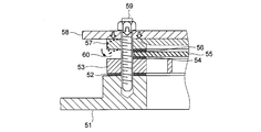
- FIG. 7 is a view showing an example of the mounting structure of the rupturable plate to the rotary machine.
- the sheet gasket 52, the grid plate 53, the sheet gasket 54, the rupture plate 55, the sheet gasket 56, the pressing plate 57, and the cover 58 are arranged in the order of the mounting seat 51 provided in the casing of the rotary machine. Will be placed.
- the rupture plate 55 is held between the holding plate 57 and the grid plate 53 by inserting and tightening the bolt 59 in the bolt holes formed in the cover 58, the holding plate 57, the grid plate 53, the sheet gasket 54 and the mounting seat 51. Be done.
- the unintended damage to the rupturable plate 55 is mainly caused by the gap 60 formed on the outer periphery of the rupturable plate 55. Under the design concept that this gap 60 makes it unnecessary to form a hole for fastening to the rupturable plate 55 itself, and the design concept of facilitating the sealing performance of the rupturable plate 55, the outer peripheral edge of the rupturable plate 55 And the grid plate 53 to form a sandwich.
- a rotary machine includes a casing, and an atmosphere release mechanism that closes an opening for release to the atmosphere provided in the casing and releases the internal fluid to the atmosphere when the internal pressure of the casing increases.
- the atmosphere release mechanism includes a rupture disc which ruptures when the internal pressure of the casing reaches a predetermined pressure, two annular clamping parts disposed so as to sandwich the outer peripheral edge of the rupture disc from both sides, and It is characterized by including a plurality of fastening members for fastening two annular clamping parts and clamping the rupture disc between the two annular clamping parts, and an annular spacer part provided along the outer periphery of the rupture disc.
- the rupture disc held by the two annular clamping parts is disposed inside the area where the fastening member is disposed, and the annular spacer part is provided along the outer periphery of the rupture disc.
- a liquid gasket may be interposed between the rupture disc and a first pinching portion positioned on the inner space side of the casing among the two annular pinching portions. If a gasket is provided between the rupture disc and the first pinching portion (e.g. grid plate), a gap corresponding to the thickness of the gasket is formed between the rupture disc and the first pinching portion. Therefore, when the change in internal pressure of the casing with the start / stop of the rotary machine is repeated, the rupture disc is repeatedly displaced by the thickness of the gasket (the size of the gap between the rupture disc and the first pinching portion). Promote unintended damage to the rupture disc.
- the gap between the rupturable plate and the first pinching portion can be obtained. Can be prevented more effectively while suppressing the repeated displacement of the rupturable plate accompanying the start and stop of the rotary machine while maintaining the high sealing performance of the squeegee.
- the annular spacer portion may be a plate-like liner formed separately from the two annular pinching portions.
- the thickness adjustment of the liner corresponding to the rupture disc becomes easy, and the rupture disc Unintended damage can be effectively prevented.
- the liner may be configured to have an elastic constant substantially equal to that of the rupturable plate or a higher elastic constant than that of the rupturable plate.
- the elastic constant of the liner is lower than that of the rupture disc, the amount of deformation of the liner may be larger than that of the rupture disc during tightening by the fastening member, and the second pinching portion may be slightly deformed. . Therefore, the outer peripheral edge of the second pinching portion can be reliably supported by the liner by configuring the liner to have an elastic constant substantially the same as that of the rupturable plate or higher than that of the rupturable plate. The deformation of the pinching portion can be prevented.
- the annular spacer portion may be a step portion formed by projecting an outer peripheral edge of one of the two annular pinching portions toward the other pinching portion side.
- the annular spacer portion may be a step portion formed by projecting an outer peripheral edge of one of the two annular pinching portions toward the other pinching portion side.
- a mounting method of an atmosphere release mechanism for a rotary machine comprises: a rupture disc which closes an opening provided in a casing of the rotary machine and ruptures when an internal pressure of the casing reaches a predetermined pressure;
- a mounting method of the atmosphere release mechanism including the two annular pinching portions for clamping the outer peripheral edge of the two from the both sides with respect to the rotary machine, wherein one of the two annular pinching portions is positioned on the inner space side of the casing Placing the rupturable plate and the liner on the first pinching portion, and the second pinching portion located on the atmosphere side of the two annular pinching portions on the rupturable plate and the liner And disposing the rupturing plate and the liner in a step of disposing the rupturing plate and the liner in a step of disposing the rupturing plate and the liner.
- the liner is positioned on the inner space side of the casing
- the mounting method of the atmosphere release mechanism by disposing the liner along the outer periphery of the rupturable plate, the force applied from the second pinching portion to the casing side by the tightening force of the fastening member is the rupturable plate and the liner Can be received substantially uniformly. Therefore, it can prevent that a 2nd pinching part deform
- annular spacer portion for example, a liner or a step portion
- the deflection of the rupture disc due to the deformation of the annular clamping portion on the atmosphere side when tightening the fastening member is suppressed.
- Unintended damage to the rupture disc due to repeated operation of the rotary machine can be prevented.
- a steam turbine provided with an atmospheric release mechanism will be described here.
- the rotary machine according to the embodiment of the present invention is not limited to a steam turbine, and includes, for example, other rotary machines equipped with an atmosphere release mechanism such as a gas turbine, a compressor, and the like.
- FIG. 1 is a cross-sectional view showing a configuration example of a steam turbine according to an embodiment of the present invention.
- the steam turbine 1 shown in FIG. 1 has a configuration in which the inner casing 3 is accommodated in the outer casing 2, and double flow (double flow) in which the steam flowing into the steam inlet passage 9 located closer to the center of the casing is branched. Method) steam turbine.
- the steam turbine 1 may be a low pressure turbine through which steam worked by the high pressure turbine or the medium pressure turbine flows.
- the steam turbine 1 has a rotor 4 covered with an outer casing 2 and an inner casing 3.
- the rotor 4 is rotatably supported by a rotor bearing outside the outer casing 2, and is provided with multistage cascade 5 in left-right symmetry along the axial direction O thereof. These wing rows 5 are covered by the inner casing 3.
- the inner casing 3 forms a plurality of bleed air chambers 6a, 6b, 6c disposed on the radially outer side of the cascade 5, and these bleed chambers 6a, 6b, 6c are each of the cascade cascade 5 of multiple stages.
- the steam of a predetermined pressure is extracted from the column and discharged to the outside.
- the rotor 4 and the inner compartment 3 are covered by the outer compartment 2.
- a steam supply pipe 7 and a steam inlet passage 9 formed by the partition wall 8 are provided to supply steam to the cascade 5 in the inner casing 3.
- an exhaust chamber 11 is formed in which the steam (exhaust gas) having passed through the cascade row 5 is discharged.
- the exhaust chamber 11 communicates with a condenser (not shown), and is maintained in vacuum during normal operation.
- the casing 10 is provided with an atmosphere release mechanism 20 for releasing the vapor in the exhaust chamber 11 to the atmosphere when the pressure in the exhaust chamber 11 abnormally rises.
- the atmosphere release mechanism 20 is arranged to close the opening 12 for the atmosphere release formed in the casing 10.
- the atmosphere releasing mechanism 20 is provided at four places on the upper surface of the casing 10.
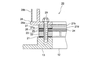
- FIG. 2 is a cross-sectional view showing a configuration example of the atmosphere opening mechanism in the embodiment of the present invention
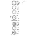
- FIG. 3 is an enlarged view of a part A of the atmosphere opening mechanism shown in FIG. It is the figure which arranged the top view of the member which comprises B in order of arrangement.
- the atmosphere releasing mechanism 20 has a hierarchical structure in which a plurality of members are stacked, and is mounted on a pedestal 13 provided on the casing 10 so as to form an opening 12 for releasing the atmosphere. Be placed.
- Each layer of the atmosphere release mechanism 20 includes a gasket 21, a grid plate 22, a gasket 23, a rupture disk 24 and a liner 25, a gasket 26, a pressing plate 27, and a cover in this order from the exhaust chamber 11 to the atmosphere. 28 may be configured.
- the layers of the atmosphere release mechanism 20 are fastened to each other by bolts 29 serving as fastening members and fixed to the casing 10.
- the pedestal 13 protrudes from the casing 10 to the atmosphere side, and the upper surface of the protrusion is an annular flat surface.
- the atmosphere release mechanism 20 is placed on the upper surface (annular flat surface) of the protrusion of the pedestal 13. Further, the pedestal 13 is provided with a plurality of bolt holes 13 a arranged along the outer periphery of the opening 12. A bolt 29 (see FIGS. 2 and 3) is screwed into the bolt hole 13a.
- the pedestal 13 may have a rib 13 b provided so as to straddle the opening 12.
- the gasket 21 is formed in an annular shape, and is interposed between the pedestal 13 and the grid plate 22 to be used for the purpose of improving the sealing performance.
- a sheet gasket is suitably used, and for example, a soft gasket, a metal gasket or a semimetal gasket is used.
- the gasket 21 also has a plurality of bolt holes 21 a corresponding to the bolt holes 13 a of the pedestal 13. The gasket 21 may not be provided.
- a plurality of grid plates 22 are formed corresponding to the annular pinching portion 22 a constituting the first pinching portion, the grid portion 22 b provided at the opening of the annular pinching portion 22 a, and the bolt holes 13 a of the pedestal 13. And bolt holes 22c.
- the grid plate 22 holds the rupture disc 24 by the annular pinching portion 22a, and prevents the rupture disc 24 from being curved toward the exhaust chamber 11 by the grid portion 22b when the inside of the exhaust chamber 11 becomes vacuum. .
- the gasket 23 is formed in an annular shape, and is interposed between the grid plate 22 and the rupture disc 24 and the liner 25 to improve the sealing performance, and is provided with high accuracy in which the rupture disc 24 and the liner 25 are installed. It is used for the purpose of forming a flat surface.
- this gasket 23 may have the same configuration as the gasket 21, it is preferable to use a liquid gasket that can be formed thinner than a sheet gasket from the viewpoint of making the gap between the grid plate 22 and the pressing plate 27 smaller.
- a silicone-based liquid gasket can be used as the liquid gasket.
- the liquid gasket may be provided only on the inner circumferential side of the plurality of bolts 29, or may be provided on the inner circumferential side and the outer circumferential side.
- the rupture disc 24 is formed in a circular shape and has a plurality of slits 24a, and is configured to rupture when it reaches a predetermined rupture pressure.
- the rupturable plate 24 can adopt a configuration in which a fluorocarbon resin sheet for securing sealing performance is held by a stainless steel thin plate in which a slit portion is formed.
- a rupture disc 24 that ruptures at a pressure slightly higher than the atmospheric pressure may be used.
- the outer peripheral edge of the rupturing plate 24 on the exhaust chamber 11 side is in contact with the annular clamping portion 22 a of the grid plate 22 through the gasket 23, and the outer peripheral edge on the atmosphere side of the retaining plate 27 described later through the gasket 26. Contact the outer edge.
- the rupturable plate 24 is held between the grid plate 22 and the holding plate 27 by bolts 29 and fixed to the casing 10.
- the bolt holes for the bolts 29 are not formed in the rupture disc 24 itself, and the bolts 29 are arranged on the outer peripheral side of the rupture disc 24 avoiding the rupture disc 24.
- the area (fastening member placement area) 30 in which the bolts 29 are arranged is an annular area between the rupture disc 24 and the liner 25 described next. That is, the rupture disc 24 and the liner 25 are not provided in the fastening member disposition area 30, and a space through which the bolt 29 passes is provided.
- bolt holes (13a, 21a, 22c, 26a, 27c, 28c) of members of different layers from the rupture disc 24 and the liner 25 are all provided corresponding to the fastening member disposition area 30, and the fastening members Bolts 29 passing through the placement area 30 are screwed into these bolt holes.
- the liner 25 constitutes an annular spacer portion, and is disposed on the outer peripheral side of the fastening member disposition area 30 so as to surround the outer periphery of the rupture disc 24. Also, the liner 25 has a thickness corresponding to the rupture disc 24. Specifically, the liner 25 has a thickness substantially the same as that of the rupturable plate 24 or a thickness slightly thinner than the rupturable plate 24 in order to facilitate transmission of a tightening force to the rupturable plate 24 side by the bolt 29. It may be formed. Furthermore, for the liner 25, a material, preferably a metal material, having an elastic constant substantially the same as that of the rupture disc 24 or higher than that of the rupture disc 24 may be used.
- the liner 25 has an elastic constant substantially the same as that of the rupturable plate 24 or an elastic constant higher than that of the rupturable plate 24, so that the outer peripheral edge of the presser plate 27 is reliably held by the liner 25 toward the casing 11. As a result, deformation of the presser plate 27 can be prevented.
- the gasket 26 is formed in an annular shape, and is interposed between the rupture disc 24 and the holding plate 27 and used for the purpose of improving the sealing performance between the two.
- the gasket 26 has substantially the same configuration as the gasket 21, and a plurality of bolt holes 26a are provided at positions corresponding to the bolt holes of members of other layers.
- the gasket 26 may not be provided.
- the presser plate 27 is formed at a position corresponding to an annular pinching portion 27a constituting a second pinching portion, a lid portion 27b closing an air side surface of the annular pinching portion, and bolt holes of members of other layers. And a plurality of bolt holes 27c.
- the pressure plate 27 is configured such that a space 27d is formed on the side facing the rupture disc 24 by the annular pinching portion 27a and the lid portion 27b (see FIG. 3), and the pressure in the exhaust chamber 11 is When the pressure reaches a predetermined value (e.g., when the pressure abnormally rises), the rupturable plate 24 bursts by bulging the rupturable plate 24 in the space 27d.
- lid 27b is provided for the purpose of preventing damage to rupturable plate 24 due to falling objects from the outside or the like, lid 27b may not be provided.
- the pressing plate 27 itself may not be provided.
- the flange portion 28a of the cover 28 described later constitutes a second pinching portion.
- the cover 28 is provided on the flange portion 28a, a frame 28b provided to bridge the opening of the flange portion 28a, and a plurality of bolts provided on the flange portion 28a at positions corresponding to the bolt holes of members of other layers. And a hole 28c.
- the bolt 29 as a fastening member is screwed into the bolt hole 13a of the base 13 through the bolt holes of the cover 28, the presser plate 27, the gasket 26, the grid plate 22 and the gasket 21. Be done. While the above components are fixed to the casing 10 side by the tightening force of the bolt 29, the rupture disc 24 and the liner 25 are held between the grid plate 22 and the holding plate 27 and these are fixed to the casing 10 side. Ru.
- the force applied from the presser plate 27 to the casing 10 by the tightening force of the bolt 29 is substantially uniformly received by the rupture disc 24 inside the bolt 29 and by the liner 25 outside the bolt 29. Therefore, deformation of the presser plate 27 can be prevented at the time of tightening, and deformation of the rupturable plate 24 can also be prevented. Therefore, in the air release mechanism 20 of the present embodiment, it is possible to prevent an unintended damage of the rupturable plate 24.
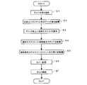
- FIG. 5 is a flowchart showing an example of the method of attaching the air release mechanism according to the embodiment of the present invention.
- the thickness of the liner 25 is adjusted corresponding to the rupture disc 24 (S1). Specifically, the thickness of the liner 25 is adjusted to be substantially the same thickness as the rupturable plate 24 or to be slightly thinner than the rupturable plate 24. Then, the gasket 21 and the grid plate 22 are disposed on the pedestal 13 provided on the casing 10 (S2), and a liquid gasket is applied as the gasket 23 on the grid plate 22 (S3). Further, the rupturable plate 24 and the liner 25 adjusted in thickness are placed on the external gasket (S4).
- the gasket 26 and the pressure plate 27 are disposed on the rupturable plate 24 and the liner 25 (S5), and the cover 28 is disposed on the pressure plate 27 (S6).
- the position of each bolt hole is made to correspond.
- the bolts 29 are inserted into the bolt holes to fasten each member to the casing (S7).
- the annular spacer portion (liner 25) having a thickness corresponding to the rupture disc 24 is provided on the outside of the fastening member disposition area 30, so that the bolt 29 is clamped when it is tightened.
- the deflection of the rupturable plate 24 due to the deformation of the plate 27 can be suppressed to prevent the unintended damage of the rupturable plate 24.
- FIG. 6 is a cross-sectional view showing a modification of the atmosphere release mechanism in the embodiment of the present invention.
- the grid plate 22 ′ includes an annular pinching portion 22a ′ which is a first pinching portion, a grid portion 22b ′, a bolt hole 22c ′, and a step portion 22d.
- the stepped portion 22d is formed by projecting a portion of the annular clamping portion 22a 'on the outer peripheral side of the bolt hole 22c' to the rupture disc 24 side.
- the surface of the stepped portion 22 d on the side of the rupture plate 24 is a flat surface in contact with the pressing plate 27 via the gasket 26.
- the stepped portion 22 d is formed at a height corresponding to the thickness of the rupture disc 24.
- the annular spacer portion As described above, by forming the annular spacer portion with the step portion 22d, the bending of the rupturable plate 24 caused by the deformation of the pressing plate 27 at the time of tightening the bolt 29 is suppressed, and the unintended damage of the rupturable plate 24 is caused. It can be prevented. Further, the annular spacer portion (step portion 22d) can be provided integrally with the grid plate 22 ', and the number of parts can be reduced.
- FIG. 6 shows the configuration in which the stepped portion 22 d is formed on the grid plate 22 ′, the stepped portion may be formed on the pressing plate 27. In this case, the gasket 26 is not provided, or a liquid gasket is used as the gasket 26.
- the configuration is not particularly limited as long as the configuration is such that the annular spacer portion (the liner 25 or the step portion) is provided outside the fastening member disposition area 30 by holding the clamping pressure by the fastening member (for example, bolt 29) by the two annular pinching portions. .
Landscapes
- Engineering & Computer Science (AREA)
- Chemical & Material Sciences (AREA)
- Combustion & Propulsion (AREA)
- Mechanical Engineering (AREA)
- General Engineering & Computer Science (AREA)
- Safety Valves (AREA)
- Sealing Devices (AREA)
- Turbine Rotor Nozzle Sealing (AREA)
- Structures Of Non-Positive Displacement Pumps (AREA)
Priority Applications (4)
| Application Number | Priority Date | Filing Date | Title |
|---|---|---|---|
| IN2098MUN2014 IN2014MN02098A (enExample) | 2012-04-27 | 2012-12-18 | |
| CN201280072610.1A CN104350239B (zh) | 2012-04-27 | 2012-12-18 | 回转机械及回转机械的大气放出机构的安装方法 |
| KR1020147029333A KR101570312B1 (ko) | 2012-04-27 | 2012-12-18 | 회전 기계 및 회전 기계의 대기 방출 기구의 설치 방법 |
| DE112012006272.8T DE112012006272B4 (de) | 2012-04-27 | 2012-12-18 | Rotationsmaschine und Befestigungsverfahren eines Ablassmechanismus an die Atmosphäre für die Rotationsmaschine |
Applications Claiming Priority (2)
| Application Number | Priority Date | Filing Date | Title |
|---|---|---|---|
| JP2012102267A JP5743100B2 (ja) | 2012-04-27 | 2012-04-27 | 回転機械及び回転機械の大気放出機構の取付方法 |
| JP2012-102267 | 2012-04-27 |
Publications (1)
| Publication Number | Publication Date |
|---|---|
| WO2013161123A1 true WO2013161123A1 (ja) | 2013-10-31 |
Family
ID=49477442
Family Applications (1)
| Application Number | Title | Priority Date | Filing Date |
|---|---|---|---|
| PCT/JP2012/082847 Ceased WO2013161123A1 (ja) | 2012-04-27 | 2012-12-18 | 回転機械及び回転機械の大気放出機構の取付方法 |
Country Status (7)
| Country | Link |
|---|---|
| US (1) | US9291100B2 (enExample) |
| JP (1) | JP5743100B2 (enExample) |
| KR (1) | KR101570312B1 (enExample) |
| CN (1) | CN104350239B (enExample) |
| DE (1) | DE112012006272B4 (enExample) |
| IN (1) | IN2014MN02098A (enExample) |
| WO (1) | WO2013161123A1 (enExample) |
Families Citing this family (2)
| Publication number | Priority date | Publication date | Assignee | Title |
|---|---|---|---|---|
| JP6037684B2 (ja) * | 2012-07-02 | 2016-12-07 | 三菱日立パワーシステムズ株式会社 | 蒸気タービン設備 |
| EP3444511B1 (de) * | 2017-08-17 | 2020-02-12 | Schunk Kohlenstofftechnik GmbH | Drucksicherung und verfahren zur herstellung |
Citations (8)
| Publication number | Priority date | Publication date | Assignee | Title |
|---|---|---|---|---|
| JPH02126001U (enExample) * | 1989-03-27 | 1990-10-17 | ||
| JPH1144371A (ja) * | 1997-07-29 | 1999-02-16 | Ishikawajima Harima Heavy Ind Co Ltd | セラミックス製破裂板 |
| WO2001012955A1 (en) * | 1999-08-11 | 2001-02-22 | Hitachi, Ltd. | Method of disassembling turbine equipment and the turbine equipment |
| JP2007205772A (ja) * | 2006-01-31 | 2007-08-16 | Matsushita Electric Works Ltd | 擬似爆風衝撃装置 |
| JP2010004656A (ja) * | 2008-06-20 | 2010-01-07 | Mitsubishi Electric Corp | 放圧板とそれを用いた放圧装置およびガス絶縁開閉装置 |
| JP2010121697A (ja) * | 2008-11-19 | 2010-06-03 | Uchiyama Manufacturing Corp | 三部材接合部のガスケット構造 |
| JP2010270761A (ja) * | 2009-03-31 | 2010-12-02 | Kubota Corp | 火花点火式エンジン |
| JP2011246871A (ja) * | 2010-05-21 | 2011-12-08 | Sekisui Jushi Co Ltd | 道路用表示板の取付構造 |
Family Cites Families (13)
| Publication number | Priority date | Publication date | Assignee | Title |
|---|---|---|---|---|
| US4232513A (en) * | 1977-10-19 | 1980-11-11 | Rolls-Royce Limited | Pressure relief panel for aircraft powerplant |
| US4207913A (en) * | 1978-01-23 | 1980-06-17 | Fike Metal Products Corporation | Low burst pressure corrosion resistant rupture disc assembly |
| EP0083473A1 (en) * | 1981-12-21 | 1983-07-13 | ELECTROFABRICATION & ENGINEERING COMPANY LIMITED | Safety pressure relief device for pressure vessels |
| US4479587A (en) * | 1983-09-06 | 1984-10-30 | Bs&B Safety Systems, Inc. | Two-way rupturable pressure relief apparatus |
| JPS6281771A (ja) | 1985-10-04 | 1987-04-15 | Sumitomo Electric Ind Ltd | シリコン・ダイアフラムの製造方法 |
| JP2882801B2 (ja) | 1988-11-02 | 1999-04-12 | 三菱重工業株式会社 | 大型節炭器管の振れ止め構造 |
| US5222862A (en) * | 1992-07-31 | 1993-06-29 | Westinghouse Electric Corp. | Turbine generator pressure relief diaphragm |
| US5327923A (en) * | 1993-02-12 | 1994-07-12 | Eischen Louis P | Valve for installation on a pressurized fluid flow line |
| JPH08226308A (ja) * | 1995-02-20 | 1996-09-03 | Babcock Hitachi Kk | ボイラ火炉の保護装置 |
| US6948515B2 (en) * | 2000-07-07 | 2005-09-27 | Zook Enterprises, Llc | Carbon rupture disk assembly |
| US6591854B1 (en) * | 2000-12-14 | 2003-07-15 | Ge Medical Systems Global Technology Company, Llc | Superconductive magnet burst disk assembly |
| WO2009107438A1 (ja) | 2008-02-27 | 2009-09-03 | 三菱重工業株式会社 | 排気室の連結構造及びタービンの支持構造並びにガスタービン |
| JP5548478B2 (ja) | 2009-03-31 | 2014-07-16 | 株式会社クボタ | 火花点火式エンジン |
-
2012
- 2012-04-27 JP JP2012102267A patent/JP5743100B2/ja active Active
- 2012-12-18 IN IN2098MUN2014 patent/IN2014MN02098A/en unknown
- 2012-12-18 DE DE112012006272.8T patent/DE112012006272B4/de active Active
- 2012-12-18 CN CN201280072610.1A patent/CN104350239B/zh active Active
- 2012-12-18 KR KR1020147029333A patent/KR101570312B1/ko active Active
- 2012-12-18 WO PCT/JP2012/082847 patent/WO2013161123A1/ja not_active Ceased
- 2012-12-28 US US13/729,402 patent/US9291100B2/en active Active
Patent Citations (8)
| Publication number | Priority date | Publication date | Assignee | Title |
|---|---|---|---|---|
| JPH02126001U (enExample) * | 1989-03-27 | 1990-10-17 | ||
| JPH1144371A (ja) * | 1997-07-29 | 1999-02-16 | Ishikawajima Harima Heavy Ind Co Ltd | セラミックス製破裂板 |
| WO2001012955A1 (en) * | 1999-08-11 | 2001-02-22 | Hitachi, Ltd. | Method of disassembling turbine equipment and the turbine equipment |
| JP2007205772A (ja) * | 2006-01-31 | 2007-08-16 | Matsushita Electric Works Ltd | 擬似爆風衝撃装置 |
| JP2010004656A (ja) * | 2008-06-20 | 2010-01-07 | Mitsubishi Electric Corp | 放圧板とそれを用いた放圧装置およびガス絶縁開閉装置 |
| JP2010121697A (ja) * | 2008-11-19 | 2010-06-03 | Uchiyama Manufacturing Corp | 三部材接合部のガスケット構造 |
| JP2010270761A (ja) * | 2009-03-31 | 2010-12-02 | Kubota Corp | 火花点火式エンジン |
| JP2011246871A (ja) * | 2010-05-21 | 2011-12-08 | Sekisui Jushi Co Ltd | 道路用表示板の取付構造 |
Also Published As
| Publication number | Publication date |
|---|---|
| US9291100B2 (en) | 2016-03-22 |
| US20130287549A1 (en) | 2013-10-31 |
| JP2013231359A (ja) | 2013-11-14 |
| IN2014MN02098A (enExample) | 2015-09-04 |
| CN104350239B (zh) | 2016-04-20 |
| KR20140138317A (ko) | 2014-12-03 |
| JP5743100B2 (ja) | 2015-07-01 |
| DE112012006272T5 (de) | 2015-02-05 |
| CN104350239A (zh) | 2015-02-11 |
| KR101570312B1 (ko) | 2015-11-18 |
| DE112012006272B4 (de) | 2016-03-24 |
Similar Documents
| Publication | Publication Date | Title |
|---|---|---|
| CN100427736C (zh) | 用双方向作用的条带型密封件对舱室空气空腔密封的装置 | |
| JP6144847B2 (ja) | バタフライ弁用シートリングとその固定構造並びに偏心型バタフライ弁 | |
| CN103161511B (zh) | 静叶栅、静叶栅装配方法以及蒸汽轮机 | |
| US8118551B2 (en) | Casing and fluid machine | |
| CN201757202U (zh) | 泄压阀 | |
| CN107939455B (zh) | 燃气轮机及其密封组件 | |
| JP2011169246A (ja) | ガスタービンケーシング構造 | |
| US20140109593A1 (en) | Coil spring hanger for exhaust duct liner | |
| EP4261443A1 (en) | Actively controlled bleed valve | |
| CN110573711A (zh) | 涡轮壳体以及具有该涡轮壳体的增压器 | |
| WO2013161123A1 (ja) | 回転機械及び回転機械の大気放出機構の取付方法 | |
| US20160312636A1 (en) | Fluid seal structure of heat engine including steam turbine | |
| JP5402004B2 (ja) | パルセーションダンパ | |
| JP2013231359A5 (enExample) | ||
| JP7306878B2 (ja) | 真空ポンプ、及び、真空ポンプ構成部品 | |
| JP5441002B2 (ja) | 遠心圧縮機用の軸シール固定構造 | |
| JP6622826B2 (ja) | タービンエンジンの熱シール | |
| CN221838950U (zh) | 一种呼吸阀和密封设备 | |
| JPH05504812A (ja) | ダイアフラム型シールプレート | |
| JP2013057282A (ja) | バイメタルシール部品及びバイメタルシール部品を用いたタービンのシール構造 | |
| ITMI20091345A1 (it) | Valvola a farfalla, preferibilmente per un circuito di sfiato di un impianto a turbina a gas | |
| JP2007327576A (ja) | 金属ガスケット及びその製造方法 | |
| JP2007315603A (ja) | 圧力容器を被覆する方法及び装置 | |
| CN223063097U (zh) | 一种蜗杆减速机 | |
| JP7086723B2 (ja) | ブレードアウト事象のための軸受バンパー |
Legal Events
| Date | Code | Title | Description |
|---|---|---|---|
| WWE | Wipo information: entry into national phase |
Ref document number: 201280072610.1 Country of ref document: CN |
|
| 121 | Ep: the epo has been informed by wipo that ep was designated in this application |
Ref document number: 12875291 Country of ref document: EP Kind code of ref document: A1 |
|
| ENP | Entry into the national phase |
Ref document number: 20147029333 Country of ref document: KR Kind code of ref document: A |
|
| WWE | Wipo information: entry into national phase |
Ref document number: 1120120062728 Country of ref document: DE Ref document number: 112012006272 Country of ref document: DE |
|
| 122 | Ep: pct application non-entry in european phase |
Ref document number: 12875291 Country of ref document: EP Kind code of ref document: A1 |