WO2013157248A1 - 変倍光学系および撮像装置 - Google Patents
変倍光学系および撮像装置 Download PDFInfo
- Publication number
- WO2013157248A1 WO2013157248A1 PCT/JP2013/002559 JP2013002559W WO2013157248A1 WO 2013157248 A1 WO2013157248 A1 WO 2013157248A1 JP 2013002559 W JP2013002559 W JP 2013002559W WO 2013157248 A1 WO2013157248 A1 WO 2013157248A1
- Authority
- WO
- WIPO (PCT)
- Prior art keywords
- lens
- lens group
- optical system
- focal length
- variable magnification
- Prior art date
- Legal status (The legal status is an assumption and is not a legal conclusion. Google has not performed a legal analysis and makes no representation as to the accuracy of the status listed.)
- Ceased
Links
Images





Classifications
-
- G—PHYSICS
- G02—OPTICS
- G02B—OPTICAL ELEMENTS, SYSTEMS OR APPARATUS
- G02B15/00—Optical objectives with means for varying the magnification
- G02B15/14—Optical objectives with means for varying the magnification by axial movement of one or more lenses or groups of lenses relative to the image plane for continuously varying the equivalent focal length of the objective
- G02B15/142—Optical objectives with means for varying the magnification by axial movement of one or more lenses or groups of lenses relative to the image plane for continuously varying the equivalent focal length of the objective having two groups only
- G02B15/1425—Optical objectives with means for varying the magnification by axial movement of one or more lenses or groups of lenses relative to the image plane for continuously varying the equivalent focal length of the objective having two groups only the first group being negative
-
- G—PHYSICS
- G02—OPTICS
- G02B—OPTICAL ELEMENTS, SYSTEMS OR APPARATUS
- G02B13/00—Optical objectives specially designed for the purposes specified below
- G02B13/001—Miniaturised objectives for electronic devices, e.g. portable telephones, webcams, PDAs, small digital cameras
- G02B13/009—Miniaturised objectives for electronic devices, e.g. portable telephones, webcams, PDAs, small digital cameras having zoom function
Definitions
- the present invention relates to a variable magnification optical system and an imaging apparatus. More specifically, the present invention relates to a variable magnification optical system that can be used for a video camera, an electronic still camera, and the like, and can be suitably used particularly as a surveillance camera. The present invention relates to a mounted imaging apparatus.
- CCTV Closed-circuit
- imaging devices such as video cameras, electronic still cameras, and surveillance cameras using an imaging device such as a CCD (Charge-Coupled Device) or CMOS (Complementary Metal-Oxide-Semiconductor) as a recording medium.
- CCD Charge-Coupled Device
- CMOS Complementary Metal-Oxide-Semiconductor
- Variable Television has been developed.
- the variable power optical system for CCTV has the advantage of being easy to use, such as the focal length and subject distance corresponding to the usage environment can be set by the user.
- the CCTV optical system whose main purpose is surveillance is required to be able to cover from a high field of view to a standard angle of view and to be used indoors or outdoors while being small.
- variable magnification optical system having a negative-positive two-group configuration composed of a negative first lens group and a positive second lens group, which has a relatively simple configuration and meets these conditions, is often used.
- the zoom lens systems described in Patent Documents 1 to 4 have been proposed as variable power optical systems having a positive, negative, negative, and positive four lens configuration and a negative / positive two lens group configuration with a zoom ratio of about 3. ing.
- Patent Documents 1 to 4 have a zoom ratio of about 2 to 3, since the F value is large, they are not satisfactory as a zoom optical system for a surveillance camera.
- the present invention has been made in view of the above circumstances, and has a variable power optical system with a variable power ratio of about 3 including a wide-angle to telephoto area, which is small and low-cost, and has high optical performance while maintaining a large aperture ratio. It is an object of the present invention to provide a system and an imaging apparatus equipped with the variable magnification optical system.
- the zoom optical system includes, in order from the object side, a first lens group having a negative refractive power, a diaphragm, and a second lens group having a positive refractive power, and zooms from the wide-angle end to the telephoto end.
- the zoom optical system is configured so that the distance between the first lens group and the second lens group in the optical axis direction is small,
- the aperture is fixed with respect to the image plane during zooming
- the first lens group includes, in order from the object side, a positive lens, a negative lens, a negative lens, and a positive meniscus lens having a convex surface facing the object side, and satisfies the following conditional expressions (1) and (2): To do.
- variable magnification optical system of the present invention is composed of a first lens group and a second lens group.
- lenses other than lenses having substantially no power lenses such as a diaphragm and a cover glass are used. It may also include an optical element, a lens flange, a lens barrel, an image sensor, a mechanism having a mechanism portion such as a camera shake correction mechanism, and the like.
- the lens surface shape such as convex surface, concave surface, plane, biconcave, meniscus, biconvex, plano-convex and plano-concave, and the sign of the refractive power of the lens such as positive and negative include aspherical surfaces. Unless otherwise noted, the paraxial region is considered. In the present invention, the sign of the radius of curvature is positive when the convex shape faces the object side and negative when the convex shape faces the image side.
- the second lens group is arranged in order from the object side.
- the lens preferably includes a convex lens, a negative lens, a biconvex lens, a negative lens, and a positive lens.
- conditional expression (4) it is preferable that the following conditional expression (4) is satisfied, and it is more preferable that the following conditional expression (4-1) is satisfied.
- variable magnification optical system according to the present invention, the following conditional expressions (5) to (7) are satisfied It is preferable that the following conditional expressions (5-1), (6-1), and (7-1) are satisfied.
- the positive lens closest to the object side of the first lens group is located on the object side. It is preferably composed of a positive meniscus lens having a convex surface and satisfies the following conditional expression
- the imaging apparatus of the present invention includes the above-described variable magnification optical system of the present invention It is characterized by that.
- the first lens group having a negative refractive power, a stop, and the second lens group having a positive refractive power are used, and the magnification is changed from the wide-angle end to the telephoto end.
- the distance between the first lens group and the second lens group in the optical axis direction is made small
- the stop is fixed with respect to the image plane at the time of zooming
- the first lens group is arranged in order from the object side.
- the zoom lens system is composed of a positive lens, a negative lens, a negative lens, and a positive meniscus lens, and satisfies the conditional expressions (1) and (2). Therefore, a variable magnification optical system can be configured in a small size and at low cost.
- a variable magnification optical system having high optical performance while having a large aperture ratio can be configured.
- variable magnification optical system of the present invention since the variable magnification optical system of the present invention is mounted, it can be configured in a small size and with high performance, and a good image can be obtained using the imaging device.
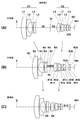
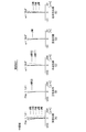
- FIG. 1 is a lens cross-sectional view illustrating a first configuration example of a variable magnification optical system according to an embodiment of the present invention and corresponding to Example 1;
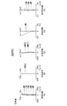
- FIG. FIG. 2 is a lens cross-sectional view illustrating a second configuration example of a variable magnification optical system and corresponding to Example 2;
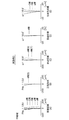
- FIG. 5 is a lens cross-sectional view illustrating a third configuration example of a variable magnification optical system and corresponding to Example 3;
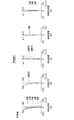
- FIG. 4 is a diagram illustrating various aberrations at the wide-angle end of the variable magnification optical system according to Example 1.
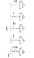
- FIG. 6 is a diagram illustrating various aberrations in the intermediate range of the variable magnification optical system according to Example 1, where (A) is spherical aberration, (B) is a sine condition violation amount, (C) is astigmatism, (D) is distortion, (E) shows lateral chromatic aberration.
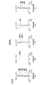
- FIG. 6 is a diagram illustrating various aberrations at the telephoto end of the variable magnification optical system according to Example 1.
- FIG. 6 is various aberration diagrams at the wide-angle end of the variable magnification optical system according to Example 2.
- (A) is spherical aberration
- (B) is a sine condition violation amount
- (C) is astigmatism
- (D) is distortion
- (E) shows lateral chromatic aberration.
- FIG. 6 is various aberration diagrams at the wide-angle end of the variable magnification optical system according to Example 2.
- (A) is spherical aberration
- (B) is a sine condition violation amount
- (C) is astigmatism
- (D) is distortion
- (E) shows lateral chromatic aberration.
- FIG. 6 is various aberration diagrams in the intermediate region of the variable magnification optical system according to Example 2, wherein (A) is spherical aberration, (B) is a sine condition violation amount, (C) is astigmatism, (D) is distortion, (E) shows lateral chromatic aberration.
- FIG. 6 is various aberration diagrams at the telephoto end of the variable magnification optical system according to Example 2.
- (A) is spherical aberration
- (B) is a sine condition violation amount
- (C) is astigmatism
- D) is distortion
- E shows lateral chromatic aberration.
- FIG. 6 is a diagram illustrating various aberrations at the wide-angle end of the variable magnification optical system according to Example 3, where (A) is spherical aberration, (B) is a sine condition violation amount, (C) is astigmatism, (D) is distortion, (E) shows lateral chromatic aberration.
- FIG. 6A is a diagram illustrating various aberrations in the intermediate range of the variable magnification optical system according to Example 3, where (A) is spherical aberration, (B) is a sine condition violation amount, (C) is astigmatism, (D) is distortion, (E) shows lateral chromatic aberration.
- FIG. 6A is a diagram illustrating various aberrations in the intermediate range of the variable magnification optical system according to Example 3, where (A) is spherical aberration, (B) is a sine condition violation amount, (C) is astigmatism, (D) is distortion, (E) shows lateral chromatic aberration.
- FIG. 6 is a diagram illustrating various aberrations at the telephoto end of the variable magnification optical system according to Example 3, where (A) is spherical aberration, (B) is a sine condition violation amount, (C) is astigmatism, (D) is distortion, (E) shows lateral chromatic aberration.
- A is spherical aberration
- B is a sine condition violation amount
- C is astigmatism
- D is distortion
- E shows lateral chromatic aberration.
- 1 is a schematic diagram of an imaging apparatus according to an embodiment of the present invention.
- FIGS. 1A, 1B, and 1C illustrate a first configuration example of a variable magnification optical system according to an embodiment of the present invention.
- This configuration example corresponds to the lens configuration of Example 1 described later.
- 1A shows the arrangement of the optical system at the wide-angle end (shortest focal length state)
- FIG. 1B shows the arrangement of the optical system in the intermediate range (intermediate focal length state)
- FIG. 1C shows the telephoto end. This corresponds to the arrangement of the optical system in the (longest focal length state).
- second and third configuration examples corresponding to lens configurations of Examples 2 and 3 to be described later are shown in FIGS. 2 (A), (B), (C) and FIGS.
- reference numeral Ri designates the surface of the most object side component as the first, and the image side (concatenation). It shows the radius of curvature of the i-th surface which is given a sign so as to increase sequentially toward the image side.
- a symbol Di indicates a surface interval on the optical axis Z between the i-th surface and the i + 1-th surface.
- symbol Di only the surface spacing (D8, D9, D18) of the part which changes with the change of imaging magnification is attached
- variable magnification optical system a first lens group G1 having a negative refractive power, an aperture stop St, and a second lens group G2 having a positive refractive power are arranged in this order from the object side along the optical axis Z.
- the zooming is performed by changing the distance between the first lens group G1 and the second lens group G2 in the optical axis direction.
- the aperture stop St is fixed with respect to the image plane Sim at the time of zooming. Note that the aperture stop St shown in FIG. 1 does not necessarily indicate the size or shape, but indicates the position on the optical axis Z.
- an imaging device such as a CCD (Charge Coupled Device) or a CMOS (Complementary Metal Oxide Semiconductor) is disposed on the image plane Sim.
- the imaging device outputs an imaging signal corresponding to an optical image formed by the variable magnification optical system of the present embodiment.
- At least the zoom optical system and the image sensor form the image pickup apparatus in the present embodiment.
- various filters such as a cover glass, a prism, an infrared cut filter, and a low-pass filter between the optical system and the image plane Sim in accordance with the configuration of the image pickup apparatus on which the variable magnification optical system is mounted.
- FIG. 1 shows an example in which a parallel plate-shaped optical member GC that assumes these is arranged between the second lens group G2 and the image plane Sim.
- the first lens group G1 includes, in order from the object side, a lens L1 that is a positive lens, a lens L2 that is a negative lens, a lens L3 that is a negative lens, and a lens L4 that is a positive meniscus lens having a convex surface facing the object side. This is a four-sheet configuration.
- the lens L2 and the lens L3 share the negative refractive power of the first lens group G1, and correct spherical aberration and off-axis coma.
- the lens L4, together with the lens L1, corrects spherical aberration, axial chromatic aberration, and lateral chromatic aberration.
- the lens L1 mainly shares the lateral chromatic aberration
- the lens L4 mainly shares the spherical aberration and the axial chromatic aberration.
- All the lenses of the first lens group G1 can be single lenses, which can reduce the cost. Further, by disposing the lens L1, which is a positive lens, on the most object side of the first lens group G1, it is possible to achieve both compactness of the entire system and securing of good imaging performance in the entire zoom range. .
- the lens L1 preferably has a convex shape on the object side, and particularly preferably has a meniscus shape with a convex surface facing the object side. As a result, the concave surface on the image side of the lens L1 reduces the refractive power compared to the case where the lens L1 is a biconvex lens or a plano-convex lens. Therefore, without increasing the refractive power of the lens L1, The overall length can be shortened.
- the lens L4 as a positive meniscus lens having a convex surface facing the object side.
- a lens L5 that is a biconvex lens, a lens L6 that is a negative lens, a lens L7 that is a biconvex lens, a lens L8 that is a negative lens, and a lens L9 that is a positive lens are arranged in order from the object side.
- the object side and image side surfaces of the lens L5 are aspherical.
- the positive refractive power is shared by the three positive lenses of the lens L5, the lens L7, and the lens L9, and various aberrations generated by the three positive lenses are corrected by the two negative lenses of the lens L6 and the lens L8. Can do.
- a low-dispersion glass material for the lens L7 and a somewhat high-dispersion glass material for the lens L9 it is possible to balance axial chromatic aberration and lateral chromatic aberration.
- the positive lens and the negative lens it is possible to suppress the occurrence of particularly high-order spherical aberration.
- the lenses L5 and L7 are biconvex lenses, which is advantageous for correcting spherical aberration. It is preferable that the lens L6 and the lens L7 are cemented, and thereby it is possible to suppress the occurrence of various aberrations due to the error of the lens interval and the influence of decentration while correcting the chromatic aberration.
- the zoom optical system of the present embodiment is configured to perform zooming by moving the first lens group G1 and the second lens group G2 along the optical axis Z and changing the group interval. That is, as the magnification is changed from the wide-angle end to the intermediate range and further to the telephoto end, the first lens group G1 and the second lens group G2 are changed from the state of FIG. 1A to the state of FIG. Further, the robot moves to the state of FIG. 1C so as to draw a locus indicated by a solid line in the drawing. More specifically, during zooming from the wide-angle end state to the telephoto end state, the distance between the first lens group G1 and the second lens group G2 moves so as to decrease. By moving each lens group in this way, it is possible to effectively perform zooming in each lens group.
- variable magnification optical system of the present embodiment has a positive lens (corresponding to the lens L1 and the lens L9) at the outermost side of the entire system with the aperture stop St as the center, and a negative lens (corresponding to the lens L2 and the lens L8) immediately inside it. Corresponding) is arranged.
- a positive lens corresponding to the lens L1 and the lens L9
- a negative lens corresponding to the lens L2 and the lens L8 immediately inside it.
- symmetry is provided with respect to the aperture stop St, off-axis aberrations caused by asymmetry are suppressed, and good imaging performance can be maintained in the entire zooming region in the entire imaging region.
- variable magnification optical system of the present embodiment is configured to satisfy the following conditional expressions (1) and (2).
- Conditional Expression (1) is an expression that defines the range of the Abbe numbers of the lens L1 and the lens L4 for maintaining good chromatic aberration.
- the Abbe number ⁇ dp becomes smaller than necessary, and the refractive power of each of the positive and negative lenses used for achromaticity in the first lens group G1 can be weakened. Although it is advantageous for correction of the above, the secondary spectrum of chromatic aberration is deteriorated, and the occurrence of color blur cannot be suppressed. If the upper limit of conditional expression (1) is exceeded, the refractive power of each of the positive and negative lenses used for achromaticity in the first lens group G1 becomes strong and the secondary spectrum is reduced, so that color blur can be corrected well.
- the amount of aberration and the amount of aberration of curvature of field increase, and the imaging performance at the on-axis and off-axis or at the wide-angle end and at the telephoto end becomes non-uniform, and a good imaging relationship cannot be maintained in the entire zoom range.
- Conditional expression (2) is an expression defining the refractive power of the lens L2, which is a negative lens. If the lower limit of conditional expression (2) is not reached, the refractive power of the lens L2 becomes too weak, and in order to maintain the zoom ratio, the refractive power of the lens L3 must be increased, and the spherical aberration at the telephoto end is reduced. Excessive correction. In addition, the back focus of the entire system is reduced, and the space for arranging the optical member GC between the lens system and the image plane Sim becomes insufficient, making it difficult to mount on the imaging apparatus. Below the lower limit of conditional expression (2), the refractive power of the lens L2 becomes too strong, and distortion at the wide-angle end increases.
- conditional expression (1-1) is satisfied instead of conditional expression (1). It is more preferable that the following conditional expression (2-1) is satisfied instead of conditional expression (2). By satisfying conditional expressions (1-1) and (2-1), the effect obtained by satisfying conditional expressions (1) and (2) can be further enhanced.
- variable magnification optical system of the present embodiment can be configured with a small size and low cost.
- a variable magnification optical system having high optical performance while having a large aperture ratio can be configured.
- variable magnification optical system of the present embodiment it is preferable that the following conditional expression (3) is satisfied with respect to the lens L1.
- f1 Focal length fw of the lens L1 of the first lens group
- fw focal length of the entire system at the wide-angle end
- the lens L1 has an overcorrected spherical aberration, which is caused by the divergence due to the negative refractive power of the entire first lens group G1, on the axis Since roles such as reducing chromatic aberration and lateral chromatic aberration are shared, it is necessary to carefully consider the distribution of the positive refractive power of the lens L1. This is defined by conditional expression (3).
- conditional expression (3) If the lower limit of conditional expression (3) is surpassed, the positive refractive power of the lens L1 becomes too strong, and if it is not cemented with the subsequent negative lens on the image side, it becomes difficult to pass off-axis light beams on the wide-angle side. Since the focal length is increased, a desired angle of view cannot be maintained. Even if they are joined, the spherical aberration and the off-axis aberration cannot be balanced, and good imaging performance cannot be obtained.
- the upper limit of conditional expression (3) is exceeded, on the contrary, the back focus becomes too long, the entire lens length becomes excessively long, and the size reduction cannot be achieved. If the upper limit of conditional expression (3) is exceeded, the positive refractive power in the first lens group G1 becomes too weak, and the spherical aberration in the first lens group G1 becomes overcorrected, and the wide-angle side and the telephoto side. In both cases, the spherical aberration cannot be kept small. At this time, if the spherical aberration is corrected by increasing the distance between the lens L1 and the succeeding negative lens on the image side, the outer diameter of the lens L1 becomes too large, and the size reduction cannot be achieved. In particular, the chromatic aberration of magnification is insufficiently corrected particularly on the wide angle side.
- conditional expression (3-1) instead of conditional expression (3).
- conditional expression (3-1) By satisfying conditional expression (3-1), the effect obtained by satisfying conditional expression (3) can be further enhanced.
- f5 focal length of the lens L5 of the second lens group G2
- fG2 focal length of the second lens group G2
- Conditional expression (4) is the focal length of the positive lens L5 of the second lens group G2 and the second lens group G2. It is a formula regarding the ratio of. In the entire system, the height of the marginal ray of the on-axis light beam is the highest in the lens L5. Therefore, the lens L5 has a great influence on specifications and performance with respect to the variable magnification optical system of the present embodiment.
- the refractive power of the lens L5 becomes too strong, the back focus of the entire system becomes small, and there is no space for placing the optical member GC between the lens system and the image plane Sim. It becomes sufficient, and mounting on an imaging device becomes difficult.
- an attempt is made to compensate for the excessive increase in the refractive power of the lens L5 by using a lens disposed on the image side of the lens L5 the amount of off-axis aberration such as curvature of field increases, resulting in image formation. Good imaging performance cannot be maintained over the entire area.
- conditional expression (4) If the upper limit of conditional expression (4) is exceeded, the refractive power of the lens L5 becomes weak, so that the refractive power of the positive lens L7 must be increased, and axial chromatic aberration including the secondary spectrum in the entire system and It becomes difficult to correct both spherical aberrations satisfactorily.
- conditional expression (4-1) is satisfied instead of conditional expression (4).
- conditional expression (4-1) the effect obtained by satisfying conditional expression (4) can be further enhanced.
- fG2F Composite focal length of three lenses L5, L6, L7 on the object side of the second lens group G2
- fG2B Composite focal length ⁇ d8 of the two lenses L8, L9 on the image side of the second lens group
- G2 Second Abbe number ⁇ d9 at the d-line of the second lens L8 from the image side of the lens group
- G2 Abbe number at the d-line of the lens L9 of the second lens group
- Conditional expression (5) is obtained from the object side of the second lens group G2.
- the positive refractive power of the front side sub lens unit becomes too weak, the back focus of the entire system becomes long, the total length of the optical system becomes long, and miniaturization cannot be achieved. Further, the field curvature is excessively corrected, and the performance in the off-axis peripheral portion is deteriorated, which is not preferable.
- the upper limit of conditional expression (5) is exceeded, the positive refractive power of the front side sub lens group will become stronger, and the second lens group G2 will become a telephoto lens, and the back focus at the wide-angle end will be shortened in the entire system. Thus, it becomes difficult to mount the imaging apparatus.
- the upper limit of conditional expression (5) is exceeded, the positive refractive power of the rear sub-lens group becomes too strong and the field curvature becomes insufficiently corrected, degrading off-axis performance.
- Conditional expressions (6) and (7) are expressions for maintaining good chromatic aberration, particularly lateral chromatic aberration, under conditions that satisfy conditional expression (5).
- Conditional expression (6) is an expression relating to the materials of the lenses L8 and L9 constituting the rear side sub lens group of the second lens group G2.
- the negative refractive power of the lens L8 becomes stronger than the positive refractive power of the lens L9, and the rear side auxiliary lens of the second lens group G2.
- the negative refractive power of the lens group becomes stronger and approaches the lower limit of conditional expression (5).
- the negative refractive power of the lens L8 becomes weaker than the positive refractive power of the lens 9, and approaches the upper limit of the conditional expression (5). That is, if the conditional expression (6) is not satisfied, the conditional expression (5) cannot be satisfied, and a problem occurs when the above-described conditional expression (5) is not satisfied.
- conditional expression (7) if the conditional expression (7) is not satisfied, the conditional expression (6) cannot be satisfied even if the chromatic aberration can be corrected, and the same problem as in the case where the conditional expression (5) is not satisfied. Arise. If chromatic aberration is corrected while satisfying conditional expression (5), the Abbe number ⁇ d9 of the lens L9 needs to be within the range of conditional expression (7). If the conditional expression (7) is not satisfied, there arises a problem that correction of chromatic aberration becomes difficult, imaging performance is deteriorated, or compactness is impaired.
- conditional expressions (5-1), (6-1), and (7-1) are satisfied instead of the conditional expressions (5) to (7).
- conditional expressions (5-1), (6-1), and (7-1) the effects obtained by satisfying conditional expressions (5) to (7) can be further enhanced.
- r1f radius of curvature of the object side surface of the lens L1 of the first lens group G1
- fw focal length of the entire system at the wide angle end
- the lens L1 of the first lens group G1 has a convex shape on the object side, By reducing the curvature radius of the surface, the overall length of the lens system can be shortened, but this curvature radius is restricted by conditional expression (3).
- the lens L1 is a positive meniscus lens that is convex on the object side, the refractive power of the lens L1 is weakened by the concave surface on the image side of the lens L1, even if the radius of curvature of the object side surface of the lens L1 is reduced.
- the overall length of the lens system regulated by conditional expression (3) can be shortened. If the lower limit of the conditional expression (8) is not reached, the lens L1 is below the lower limit of the conditional expression (3). When exceeding the upper limit of the conditional expression (8), the lens L1 exceeds the upper limit of the conditional expression (3), so that the same problem as when exceeding the upper limit of the conditional expression (3) occurs.
- FIG. 13 shows a schematic configuration diagram of an imaging apparatus using the variable magnification optical system of the embodiment of the present invention as an example of the imaging apparatus of the embodiment of the present invention.
- the imaging device include a digital camera, a video camera, a surveillance camera, and the like using an imaging device such as a CCD or a CMOS.
- An imaging apparatus 10 illustrated in FIG. 13 includes a variable magnification optical system 1, a filter 2 disposed on the image side of the variable magnification optical system 1, and an imaging element that captures an image of a subject formed by the variable magnification optical system 1. 3, a signal processing unit 4 that performs arithmetic processing on an output signal from the imaging device 3, and a zoom control unit 5 that performs zooming of the zooming optical system 1 and focus adjustment using the zooming.
- the variable magnification optical system 1 includes a first lens group G1 having a negative refractive power that changes magnification by moving along the optical axis Z, an aperture stop St, and an optical axis Z similar to the first lens group G1. And a second lens group G2 having a positive refractive power that performs zooming by moving along the lens.
- FIG. 13 schematically shows each lens group.
- the image pickup device 3 converts an optical image formed by the variable magnification optical system 1 into an electric signal, and the image pickup surface thereof is disposed so as to coincide with the image plane of the variable magnification optical system 1.
- a CCD or a CMOS can be used as the imaging element 3.
- variable magnification optical system By using the variable magnification optical system according to the present embodiment as the variable magnification optical system 1 in such an image pickup apparatus, a high resolution image pickup signal can be obtained.
- variable magnification optical system According to the present embodiment, specific examples of the variable magnification optical system according to the present embodiment will be described.
- Example 1A, 1B, and 1C are diagrams illustrating the configuration of a variable magnification optical system according to Example 1 of the present invention. Since the detailed description of the lens group and each lens in the configuration of FIG. 1 is as described above, the redundant description is omitted below unless otherwise required.
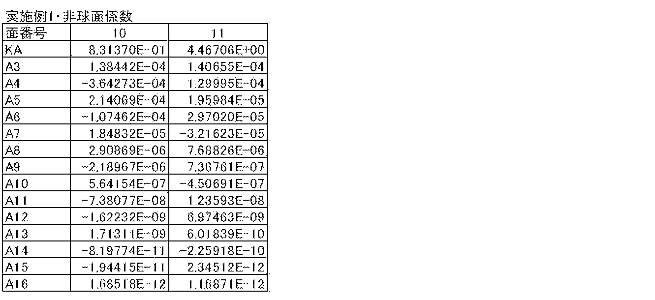
- Tables 1 to 3 show specific lens data corresponding to the configuration of the imaging lens of Example 1 shown in FIG. Table 1 shows the basic lens data, Table 2 shows other data, and Table 3 shows aspheric data.
- Si column in the lens data shown in Table 1 in the variable magnification optical system according to Example 1, the surface of the component closest to the object side is the first, and is increased sequentially toward the image side.
- the value (mm) of the radius of curvature of the i-th surface from the object side is shown in correspondence with the reference symbol Ri in FIG.
- the column of the surface interval Di indicates the interval (mm) on the optical axis between the i-th surface Si and the i + 1-th surface Si + 1 from the object side.
- the Abbe number of the j-th optical element with respect to the d-line is shown.
- the symbol “*” attached to the left side of the surface number indicates that the lens surface is aspherical.
- the basic lens data in Table 1 shows numerical values of paraxial curvature radii as the curvature radii of these aspheric surfaces.
- Table 2 also shows other data such as zoom magnification, paraxial focal length f (mm), back focus Bf, and F value (FNo) in the infinite focus state at the wide-angle end, intermediate range, and telephoto end. .) And angle of view (2 ⁇ ) values are also shown.
- the distance D8 between the first lens group G1 and the aperture stop St, the aperture stop St The distance D9 between the second lens group G2 and the distance D18 between the second lens group and the optical member GC are variable.
- Table 2 shows zoom intervals (mm) in the infinitely focused state at the wide-angle end, the intermediate range, and the telephoto end as data at the time of zooming of the surface intervals D8, D9, and D18.
- Table 3 shows aspherical data of the variable magnification optical system according to Example 1.
- E indicates that the subsequent numerical value is a “power exponent” with a base of 10
- the numerical value represented by an exponential function with the base of 10 is Indicates that the value before “E” is multiplied.
- “1.0E-02” indicates “1.0 ⁇ 10 ⁇ 2 ”.
- Zd C ⁇ h 2 / ⁇ 1+ (1 ⁇ KA ⁇ C 2 ⁇ h 2 ) 1/2 ⁇ + ⁇ Am ⁇ h m
- Zd Depth of aspheric surface (length of a perpendicular line drawn from a point on the aspherical surface at height h to a plane perpendicular to the optical axis where the aspherical vertex contacts)
- h Height (distance from the optical axis to the lens surface)
- C Reciprocal number KA of paraxial radius of curvature
- mm is used as the unit of length and degrees (°) are used as the unit of angle as described above, but the optical system can be used with proportional expansion or proportional reduction. Therefore, other suitable units can be used.
- Examples 2 and 3 are diagrams showing the configuration of a variable magnification optical system according to Example 2 of the present invention
- FIGS. 3A, 3B, and 3C are diagrams illustrating the present invention. It is a figure which shows the structure of the variable magnification optical system which concerns on Example 3.
- the variable magnification optical system according to Examples 2 and 3 has substantially the same configuration as the variable magnification optical system according to Example 1.
- Table 10 shows a summary of the values for the above conditional expressions for each example. As can be seen from Table 10, with respect to conditional expressions (1) to (8), the values of the respective examples are within the numerical range.
- [Aberration performance] 4A to 4E respectively show spherical aberration at the wide-angle end, aberration for sine condition violation amount, astigmatism, distortion aberration, and lateral chromatic aberration in the variable magnification optical system according to Example 1.
- . 5A to 5E show similar aberrations in the intermediate range
- FIGS. 6A to 6E show similar aberrations at the telephoto end.
- Each aberration diagram shows an aberration with the d-line (587.6 nm) as a reference wavelength.
- the spherical aberration diagram also shows aberrations at a wavelength of 656.3 nm (C line), a wavelength of 486.1 nm (F line), a wavelength of 435.8 nm (g line), and a wavelength of 852.1 nm (s line).
- the solid line indicates the sagittal direction and the broken line indicates the tangential direction.
- FNo. Indicates an F value, and ⁇ indicates a half angle of view.
- the lateral chromatic aberration diagram shows aberrations for the C-line, F-line, and g-line.
- FIGS. 7A to 7E wide-angle end
- FIGS. 8A to 8E intermediate region
- FIG. 9A Shown in (E) (telephoto end).
- FIGS. 10 to 12 (A) to (E) various aberrations of the variable magnification optical system according to Example 3 are shown in FIGS. 10 to 12 (A) to (E).
- variable aberrations are successfully corrected for each embodiment, and a variable-magnification optical system that is reduced in size as a whole can be realized.
- this invention is not limited to the said embodiment and each Example, Various deformation
- the values of the radius of curvature, the surface interval, and the refractive index of each lens component are not limited to the values shown in the above numerical examples, and may take other values.
Landscapes
- Physics & Mathematics (AREA)
- General Physics & Mathematics (AREA)
- Optics & Photonics (AREA)
- Lenses (AREA)
- Nonlinear Science (AREA)
Description
本発明は、変倍光学系および撮像装置に関し、より詳しくは、ビデオカメラや電子スチルカメラ等に使用可能で、とくに監視カメラ用途として好適に使用可能な変倍光学系およびこの変倍光学系を搭載した撮像装置に関するものである。
従来、CCD(Charge Coupled Device)やCMOS(Complementary Metal Oxide Semiconductor)等の撮像素子を記録媒体とするビデオカメラや電子スチルカメラ、監視カメラ等の撮像装置に用いられる光学系として、CCTV(Closed-circuit Television)用の変倍光学系が開発されている。CCTV用変倍光学系は、使用環境に応じた焦点距離、被写体距離を使用者側で設定できる等、使い勝手が良いという利点がある。監視が主目的となるCCTV用光学系には、小型でありながら、高視野領域から標準画角までカバーでき、かつ室内や屋外での使用にも耐えることが求められる。このため、比較的構成が簡易でこれらの条件に適う、負の第1レンズ群と正の第2レンズ群からなる負正2群構成の変倍光学系が多用されている。例えば、第1レンズ群を正、負、負、正の4枚構成とし、変倍比3程度の負正2群構成の変倍光学系として、特許文献1~4に記載のものが提案されている。
ところで、近年では監視カメラ市場がとみに拡大してきたことから開発競争が激化しており、低照度の撮影条件下でも使用可能なように大口径比である等の高諸元を満たし、高い結像性能を有しながら、小型かつ低コストに構成されたレンズ系の開発が強く求められている。さらに、近年では一般的な監視目的だけでなく、自動車のプレート標識が読み取れるといったような、より高解像で、より高倍率に撮像できる、広角から望遠の領域を含み、可視域から近赤外域までの使用を想定した簡易で使い勝手の良い変倍光学系への要請が多くなってきた。
上記特許文献1~4に記載されたものは、変倍比が2~3程度であるものの、F値が大きいため、監視カメラ用の変倍光学系としては満足のいくものではない。
本発明は上記事情に鑑みてなされたもので、小型かつ低コストに構成され、大口径比でありながら高い光学性能を確保した、広角から望遠の領域を含む変倍比3程度の変倍光学系およびこの変倍光学系を搭載した撮像装置を提供することを目的とする。
本発明による変倍光学系は、物体側から順に、負の屈折力を有する第1レンズ群、絞り、および正の屈折力を有する第2レンズ群からなり、広角端から望遠端へ変倍する際に、第1レンズ群と第2レンズ群との光軸方向の間隔が小さくなるように構成された変倍光学系であって、
絞りが、変倍時に像面に対して固定されており、
第1レンズ群が、物体側から順に、正レンズ、負レンズ、負レンズ、および物体側に凸面を向けた正メニスカスレンズからなり
下記条件式(1)、(2)を満足することを特徴とするものである。
絞りが、変倍時に像面に対して固定されており、
第1レンズ群が、物体側から順に、正レンズ、負レンズ、負レンズ、および物体側に凸面を向けた正メニスカスレンズからなり
下記条件式(1)、(2)を満足することを特徴とするものである。
22<νdp<47 … (1)
-5.00<f2/fw<-1.20 … (2)
ただし、
νdp:第1レンズ群の最も物体側の正レンズおよび最も像側の正メニスカスレンズのd線における平均アッベ数
fw:広角端における全系の焦点距離
f2:第1レンズ群の物体側から2番目に配置された負レンズの焦点距離
なお、本発明による変倍光学系においては、下記条件式(1-1)を満足することが好ましい。また、下記条件式(2-1)を満足することが好ましい。
-5.00<f2/fw<-1.20 … (2)
ただし、
νdp:第1レンズ群の最も物体側の正レンズおよび最も像側の正メニスカスレンズのd線における平均アッベ数
fw:広角端における全系の焦点距離
f2:第1レンズ群の物体側から2番目に配置された負レンズの焦点距離
なお、本発明による変倍光学系においては、下記条件式(1-1)を満足することが好ましい。また、下記条件式(2-1)を満足することが好ましい。
24<νdp<44 … (1-1)
-4.00<f2/fw<-2.00 … (2-1)
本発明の変倍光学系は、第1レンズ群および第2レンズ群からなるものであるが、2つのレンズ群以外に,実質的にパワーを持たないレンズ、絞りやカバーガラス等のレンズ以外の光学要素、レンズフランジ、レンズバレル、撮像素子、手ぶれ補正機構等の機構部分等を持つものも含むものであってもよい。
-4.00<f2/fw<-2.00 … (2-1)
本発明の変倍光学系は、第1レンズ群および第2レンズ群からなるものであるが、2つのレンズ群以外に,実質的にパワーを持たないレンズ、絞りやカバーガラス等のレンズ以外の光学要素、レンズフランジ、レンズバレル、撮像素子、手ぶれ補正機構等の機構部分等を持つものも含むものであってもよい。
また、本発明においては、凸面、凹面、平面、両凹、メニスカス、両凸、平凸および平凹等といったレンズの面形状、正および負といったレンズの屈折力の符号は、非球面が含まれているものについてはとくに断りのない限り近軸領域で考えるものとする。また、本発明においては、曲率半径の符号は、面形状が物体側に凸面を向けた場合を正、像側に凸面を向けた場合を負とすることにする。
また、本発明による変倍光学系においては、下記条件式(3)を満足することが好ましく、下記条件式(3-1)を満足することがより好ましい。
3<f1/fw<17 … (3)
6<f1/fw<14 … (3-1)
ただし、
f1:第1レンズ群の最も物体側の正レンズの焦点距離
fw:広角端における全系の焦点距離
また、本発明による変倍光学系においては、第2レンズ群が、物体側から順に、両凸レンズ、負レンズ、両凸レンズ、負レンズ、および正レンズからなることが好ましい。
6<f1/fw<14 … (3-1)
ただし、
f1:第1レンズ群の最も物体側の正レンズの焦点距離
fw:広角端における全系の焦点距離
また、本発明による変倍光学系においては、第2レンズ群が、物体側から順に、両凸レンズ、負レンズ、両凸レンズ、負レンズ、および正レンズからなることが好ましい。
この場合、下記条件式(4)を満足することが好ましく、下記条件式(4-1)を満足することがより好ましい。
0.3<f5/fG2<1.5 … (4)
0.6<f5/fG2<1.2 … (4-1)
ただし、
f5:第2レンズ群の最も物体側の両凸レンズの焦点距離
fG2:第2レンズ群の焦点距離
また、本発明による変倍光学系においては、下記条件式(5)~(7)を満足することが好ましく、下記条件式(5-1)、(6-1)、(7-1)を満足することがより好ましい。
0.6<f5/fG2<1.2 … (4-1)
ただし、
f5:第2レンズ群の最も物体側の両凸レンズの焦点距離
fG2:第2レンズ群の焦点距離
また、本発明による変倍光学系においては、下記条件式(5)~(7)を満足することが好ましく、下記条件式(5-1)、(6-1)、(7-1)を満足することがより好ましい。
-0.1<fG2F/fG2B<0.1 … (5)
-5<νd8-νd9<10 … (6)
29<νd9<37 … (7)
-0.05<fG2F/fG2B<0.05 … (5-1)
0<νd8-νd9<5 … (6-1)
31<νd9<36 … (7-1)
ただし、
fG2F:第2レンズ群の物体側の3枚のレンズの合成焦点距離
fG2B:第2レンズ群の像側の2枚のレンズの合成焦点距離
νd8:第2レンズ群の像側から2番目の負レンズのd線におけるアッベ数
νd9:第2レンズ群の正レンズのd線におけるアッベ数
また、本発明による変倍光学系においては、第1レンズ群の最も物体側の正レンズが、物体側に凸面を向けた正メニスカスレンズからなり、下記条件式(8)を満足することが好ましい。
-5<νd8-νd9<10 … (6)
29<νd9<37 … (7)
-0.05<fG2F/fG2B<0.05 … (5-1)
0<νd8-νd9<5 … (6-1)
31<νd9<36 … (7-1)
ただし、
fG2F:第2レンズ群の物体側の3枚のレンズの合成焦点距離
fG2B:第2レンズ群の像側の2枚のレンズの合成焦点距離
νd8:第2レンズ群の像側から2番目の負レンズのd線におけるアッベ数
νd9:第2レンズ群の正レンズのd線におけるアッベ数
また、本発明による変倍光学系においては、第1レンズ群の最も物体側の正レンズが、物体側に凸面を向けた正メニスカスレンズからなり、下記条件式(8)を満足することが好ましい。
4<r1f/fw<9 … (8)
ただし、
r1f:第1レンズ群の最も物体側の正レンズの物体側の面の曲率半径
fw:広角端における全系の焦点距離
本発明の撮像装置は、上記記載の本発明の変倍光学系を搭載したことを特徴とするものである。
ただし、
r1f:第1レンズ群の最も物体側の正レンズの物体側の面の曲率半径
fw:広角端における全系の焦点距離
本発明の撮像装置は、上記記載の本発明の変倍光学系を搭載したことを特徴とするものである。
本発明によれば、物体側から順に、負の屈折力を有する第1レンズ群、絞り、および正の屈折力を有する第2レンズ群とからなるものとし、広角端から望遠端へ変倍する際に、第1レンズ群と第2レンズ群との光軸方向の間隔が小さくなるように構成し、絞りを変倍時に像面に対して固定し、第1レンズ群を、物体側から順に、正レンズ、負レンズ、負レンズおよび正メニスカスレンズからなるものとし、条件式(1)、(2)を満足するものとしたため、小型かつ低コストに変倍光学系を構成できる。また、大口径比でありながら高い光学性能を有する変倍光学系を構成できる。
本発明の撮像装置によれば、本発明の変倍光学系を搭載しているため、小型で高性能に構成でき、撮像素子を用いて良好な像を得ることができる。
以下、本発明の実施形態について図面を参照して詳細に説明する。図1(A),(B),(C)は、本発明の一実施形態に係る変倍光学系の第1の構成例を示している。この構成例は、後述の実施例1のレンズ構成に対応している。なお、図1(A)は広角端(最短焦点距離状態)での光学系配置、図1(B)は中間域(中間焦点距離状態)での光学系配置、図1(C)は望遠端(最長焦点距離状態)での光学系配置に対応している。同様にして、後述の実施例2,3のレンズ構成に対応する第2および第3の構成例を、図2(A),(B),(C)および図3(A),(B),(C)に示す。図1(A),(B),(C)~図3(A),(B),(C)において、符号Riは、最も物体側の構成要素の面を1番目として、像側(結像側)に向かうに従い順次増加するようにして符号を付したi番目の面の曲率半径を示す。符号Diは、i番目の面とi+1番目の面との光軸Z上の面間隔を示す。なお符号Diについては、撮影倍率の変化に伴って変化する部分の面間隔(D8,D9,D18)のみ符号を付す。
この変倍光学系は、光軸Zに沿って物体側から順に、負の屈折力を有する第1レンズ群G1、開口絞りSt、および正の屈折力を有する第2レンズ群G2が配置されてなり、第1レンズ群G1と第2レンズ群G2との光軸方向の間隔を変化させることにより変倍を行うように構成されている。また、この変倍光学系では、開口絞りStは変倍時に像面Simに対して固定されている。なお、図1に示す開口絞りStは必ずしも大きさや形状を表すものではなく、光軸Z上の位置を示すものである。
この変倍光学系を撮像装置に適用する際には、像面SimにはCCD(Charge Coupled Device)やCMOS(Complementary Metal Oxide Semiconductor)等の撮像素子が配置される。撮像素子は、本実施形態の変倍光学系によって形成された光学像に応じた撮像信号を出力するものである。少なくとも、この変倍光学系および撮像素子により、本実施形態における撮像装置が構成される。また、この変倍光学系を装着する撮像装置側の構成に応じて、光学系と像面Simとの間にカバーガラス、プリズム、赤外線カットフィルタやローパスフィルタ等の各種フィルタを配置することが好ましい。図1では、これらを想定した平行平板状の光学部材GCを第2レンズ群G2と像面Simとの間に配置した例を示している。
第1レンズ群G1は、物体側から順に、正レンズであるレンズL1、負レンズであるレンズL2、負レンズであるレンズL3および物体側に凸面を向けた正メニスカスレンズであるレンズL4が配置されてなる4枚構成である。
レンズL2およびレンズL3は、第1レンズ群G1の負の屈折力を分担し、球面収差および軸外のコマ収差を補正する。レンズL4はレンズL1とともに、球面収差、軸上色収差および倍率色収差を補正する。レンズL1との役割では、倍率色収差はレンズL1が主に分担し、球面収差および軸上色収差はレンズL4が主に分担する。
第1レンズ群G1のレンズは、全て単レンズとすることができ、これにより、低コスト化を図ることができる。また、第1レンズ群G1の最も物体側に正レンズであるレンズL1を配置することにより、全系のコンパクト化および全変倍域での良好な結像性能確保を両立させることが可能になる。レンズL1は、物体側に凸形状を有するものとすることが好ましく、とくに物体側に凸面を向けたメニスカス形状を有するものとすることが好ましい。これにより、レンズL1の像側の凹面によって、レンズL1を両凸レンズあるいは平凸レンズとした場合と比較して屈折力が弱くなるため、レンズL1の屈折力を強くすることなく、変倍光学系の全長を短くすることができる。
レンズL4を、物体側に凸面を向けた正のメニスカスレンズとすることにより、望遠側での球面収差、および広角側での非点収差を良好に補正することが可能となる。
第2レンズ群G2は、物体側から順に、両凸レンズであるレンズL5、負レンズであるレンズL6、両凸レンズであるレンズL7、負レンズであるレンズL8、および正レンズであるレンズL9が配置されてなる5枚構成である。レンズL5の物体側および像側の面は非球面で構成されている。
レンズL5、レンズL7およびレンズL9の3枚の正レンズで正の屈折力を分担し、レンズL6およびレンズL8の2枚の負レンズにより、3枚の正レンズで発生する諸収差を補正することができる。とくにレンズL7に低分散の硝材を使用し、レンズL9にはやや高分散の硝材を使用することにより、軸上色収差と倍率色収差とのバランスをとることが可能となる。また、正レンズおよび負レンズを交互に配置することにより、とくに高次の球面収差の発生を抑えることができる。また、レンズL5およびレンズL7を両凸レンズとすることにより、球面収差の補正に有利となる。レンズL6とレンズL7とは接合されていることが好ましく、これにより、色収差を補正しつつ、レンズ間隔の誤差および偏心の影響による諸収差の発生を抑えることができる。
本実施形態の変倍光学系は、第1レンズ群G1および第2レンズ群G2を光軸Zに沿って移動させて、群間隔を変化させることにより変倍を行うように構成されている。すなわち、広角端から中間域へ、さらに望遠端へと変倍させるに従い、第1レンズ群G1および第2レンズ群G2は、例えば図1(A)の状態から図1(B)の状態へ、さらに図1(C)の状態へと、図に実線で示した軌跡を描くように移動する。より詳しくは、広角端状態から望遠端状態への変倍に際し、第1レンズ群G1と第2レンズ群G2との間隔が減少するように移動する。このように各レンズ群を移動することで、各レンズ群で効果的に変倍を行うことができる。
また、本実施形態の変倍光学系は、開口絞りStを中心として、全系の最も外側に正レンズ(レンズL1、レンズL9に対応)、そのすぐ内側に負レンズ(レンズL2、レンズL8に対応)を配置した構成となっている。これにより、開口絞りStに対して対称性を持たせて、非対称性により発生する軸外諸収差を抑え、結像領域全域において、良好な結像性能を全変倍域で維持することができる。
また、本実施形態の変倍光学系においては、下記条件式(1)、(2)を満足するように構成されている。
22<νdp<47 … (1)
-5.00<f2/fw<-1.20 … (2)
ただし、
νdp:第1レンズ群G1の正レンズであるレンズL1および正メニスカスレンズであるレンズL4のd線における平均アッベ数
fw:広角端における全系の焦点距離
f2:第1レンズ群G1の物体側から2番目に配置された負レンズであるレンズL2の焦点距離
条件式(1)は、色収差を良好に維持するためのレンズL1およびレンズL4のアッベ数の範囲を規定した式である。条件式(1)の下限を下回ると、アッベ数νdpが必要以上に小さくなり、第1レンズ群G1内の色消しに用いられる正負レンズ各々の屈折力を弱くできるため、球面収差および像面湾曲の補正には有利であるが、色収差の2次スペクトルを悪化させ、色滲みの発生を抑えきれなくなる。条件式(1)の上限を上回ると、第1レンズ群G1内の色消しに用いられる正負レンズ各々の屈折力が強くなり、2次スペクトルが減少して色滲みは良好に補正可能だが、球面収差および像面湾曲の収差発生量が大きくなり、軸上と軸外あるいは広角端と望遠端での結像性能が不均一となり、全変倍域で良好な結像関係を維持できなくなる。
-5.00<f2/fw<-1.20 … (2)
ただし、
νdp:第1レンズ群G1の正レンズであるレンズL1および正メニスカスレンズであるレンズL4のd線における平均アッベ数
fw:広角端における全系の焦点距離
f2:第1レンズ群G1の物体側から2番目に配置された負レンズであるレンズL2の焦点距離
条件式(1)は、色収差を良好に維持するためのレンズL1およびレンズL4のアッベ数の範囲を規定した式である。条件式(1)の下限を下回ると、アッベ数νdpが必要以上に小さくなり、第1レンズ群G1内の色消しに用いられる正負レンズ各々の屈折力を弱くできるため、球面収差および像面湾曲の補正には有利であるが、色収差の2次スペクトルを悪化させ、色滲みの発生を抑えきれなくなる。条件式(1)の上限を上回ると、第1レンズ群G1内の色消しに用いられる正負レンズ各々の屈折力が強くなり、2次スペクトルが減少して色滲みは良好に補正可能だが、球面収差および像面湾曲の収差発生量が大きくなり、軸上と軸外あるいは広角端と望遠端での結像性能が不均一となり、全変倍域で良好な結像関係を維持できなくなる。
条件式(2)は、負レンズであるレンズL2の屈折力を規定した式である。条件式(2)の下限を下回ると、レンズL2の屈折力が弱くなり過ぎ、変倍比を維持するためにはレンズL3の屈折力を強くせざるを得ず、望遠端での球面収差が補正過剰となる。また、全系のバックフォーカスが小さくなり、レンズ系と像面Simとの間に光学部材GCを配置するスペースが不十分になり、撮像装置への搭載が困難になる。条件式(2)の下限を下回ると、レンズL2の屈折力が強くなり過ぎ、広角端での歪曲収差が増大する。
さらに、条件式(1)に代えて下記条件式(1-1)を満足することがより好ましい。また、条件式(2)に代えて下記条件式(2-1)を満足することがより好ましい。条件式(1-1)、(2-1)を満足することで、条件式(1)、(2)を満足することにより得られる効果をさらに高めることができる。
24<νdp<44 … (1-1)
-4.00<f2/fw<-2.00 … (2-1)
本実施形態の変倍光学系は、このような構成により、小型かつ低コストに変倍光学系を構成できる。また、大口径比でありながら高い光学性能を有する変倍光学系を構成できる。
-4.00<f2/fw<-2.00 … (2-1)
本実施形態の変倍光学系は、このような構成により、小型かつ低コストに変倍光学系を構成できる。また、大口径比でありながら高い光学性能を有する変倍光学系を構成できる。
以下、本実施形態の撮像レンズの好ましい構成について説明する。
本実施形態の変倍光学系においては、レンズL1に関して、下記条件式(3)を満足することが好ましい。
3<f1/fw<17 … (3)
ただし、
f1:第1レンズ群のレンズL1の焦点距離
fw:広角端における全系の焦点距離
レンズL1は、第1レンズ群G1全体の負の屈折力による発散性で生じる補正過剰な球面収差、軸上色収差および倍率色収差を低減する等の役割を分担しているため、レンズL1の正の屈折力の配分を慎重に考慮する必要がある。これを規定したのが条件式(3)である。条件式(3)の下限を下回ると、レンズL1の正の屈折力が強くなり過ぎ、像側の後続の負レンズと接合しなければ広角側での軸外光束を通しにくくなり、広角端の焦点距離を長くすることとなって所望の画角を維持できなくなる。また、仮に接合したとしても、球面収差と軸外収差とのバランスがとれなくなり、良好な結像性能が得られない。
ただし、
f1:第1レンズ群のレンズL1の焦点距離
fw:広角端における全系の焦点距離
レンズL1は、第1レンズ群G1全体の負の屈折力による発散性で生じる補正過剰な球面収差、軸上色収差および倍率色収差を低減する等の役割を分担しているため、レンズL1の正の屈折力の配分を慎重に考慮する必要がある。これを規定したのが条件式(3)である。条件式(3)の下限を下回ると、レンズL1の正の屈折力が強くなり過ぎ、像側の後続の負レンズと接合しなければ広角側での軸外光束を通しにくくなり、広角端の焦点距離を長くすることとなって所望の画角を維持できなくなる。また、仮に接合したとしても、球面収差と軸外収差とのバランスがとれなくなり、良好な結像性能が得られない。
条件式(3)の上限を上回ると、逆にバックフォーカスが長くなり過ぎて、全系のレンズ全長が過度に長くなり、小型化を達成できなくなる。また、条件式(3)の上限を上回ると、第1レンズ群G1内の正の屈折力が弱くなり過ぎて、第1レンズ群G1内での球面収差が補正過剰となり、広角側と望遠側との双方で球面収差を小さく抑えることができなくなる。この際、レンズL1と像側の後続の負レンズとの間隔を大きくして球面収差を補正すると、レンズL1の外径が大きくなり過ぎてしまい、小型化を達成できなくなる。また、とくに広角側で倍率の色収差が補正不足となる。
なお、条件式(3)に代えて下記条件式(3-1)を満足することがより好ましい。条件式(3-1)を満足することで、条件式(3)を満足することにより得られる効果をさらに高めることができる。
6<f1/fw<14 … (3-1)
また、本実施形態の変倍光学系においては、下記条件式(4)を満足することが好ましい。
また、本実施形態の変倍光学系においては、下記条件式(4)を満足することが好ましい。
0.3<f5/fG2<1.5 … (4)
ただし、
f5:第2レンズ群G2のレンズL5の焦点距離
fG2:第2レンズ群G2の焦点距離
条件式(4)は、第2レンズ群G2の正のレンズL5と第2レンズ群G2との焦点距離の比に関する式である。全系において軸上光束のマージナル光線の光線高さはレンズL5で最も高いため、レンズL5は本実施形態の変倍光学系に対する仕様および性能面での影響が大きい。条件式(4)の下限を下回ると、レンズL5の屈折力が強くなり過ぎて、全系のバックフォーカスが小さくなり、レンズ系と像面Simとの間に光学部材GCを配置するスペースが不十分となり、撮像装置への搭載が困難になる。この際、レンズL5の屈折力が強くなり過ぎた分を、レンズL5よりも像側に配置されたレンズで補償しようとすると、像面湾曲等の軸外収差の発生量が大きくなり、結像領域全体で良好な結像性能を維持できなくなる。条件式(4)の上限を上回ると、レンズL5の屈折力が弱くなるため、正のレンズL7の屈折力を強くしなければならなくなり、全系での2次スペクトルを含めた軸上色収差および球面収差の双方を良好に補正することが困難となる。
ただし、
f5:第2レンズ群G2のレンズL5の焦点距離
fG2:第2レンズ群G2の焦点距離
条件式(4)は、第2レンズ群G2の正のレンズL5と第2レンズ群G2との焦点距離の比に関する式である。全系において軸上光束のマージナル光線の光線高さはレンズL5で最も高いため、レンズL5は本実施形態の変倍光学系に対する仕様および性能面での影響が大きい。条件式(4)の下限を下回ると、レンズL5の屈折力が強くなり過ぎて、全系のバックフォーカスが小さくなり、レンズ系と像面Simとの間に光学部材GCを配置するスペースが不十分となり、撮像装置への搭載が困難になる。この際、レンズL5の屈折力が強くなり過ぎた分を、レンズL5よりも像側に配置されたレンズで補償しようとすると、像面湾曲等の軸外収差の発生量が大きくなり、結像領域全体で良好な結像性能を維持できなくなる。条件式(4)の上限を上回ると、レンズL5の屈折力が弱くなるため、正のレンズL7の屈折力を強くしなければならなくなり、全系での2次スペクトルを含めた軸上色収差および球面収差の双方を良好に補正することが困難となる。
また、条件式(4)に代えて下記条件式(4-1)を満足することがより好ましい。条件式(4-1)を満足することで、条件式(4)を満足することにより得られる効果をさらに高めることができる。
0.6<f5/fG2<1.2 … (4-1)
また、本実施形態の変倍光学系においては、下記条件式(5)~(7)を満足することが好ましい。
また、本実施形態の変倍光学系においては、下記条件式(5)~(7)を満足することが好ましい。
-0.1<fG2F/fG2B<0.1 … (5)
-5<νd8-νd9<10 … (6)
29<νd9<37 … (7)
ただし、
fG2F:第2レンズ群G2の物体側の3枚のレンズL5,L6,L7の合成焦点距離
fG2B:第2レンズ群G2の像側の2枚のレンズL8,L9の合成焦点距離
νd8:第2レンズ群G2の像側から2番目のレンズL8のd線におけるアッベ数
νd9:第2レンズ群G2のレンズL9のd線におけるアッベ数
条件式(5)は、第2レンズ群G2の物体側の3枚のレンズL5,L6,L7からなる前側副レンズ群の合成焦点距離f2GFと、第2レンズ群G2の像側の2枚のレンズL8,L9からなる後側副レンズ群の合成焦点距離f2GBとの関係を規定する式である。
-5<νd8-νd9<10 … (6)
29<νd9<37 … (7)
ただし、
fG2F:第2レンズ群G2の物体側の3枚のレンズL5,L6,L7の合成焦点距離
fG2B:第2レンズ群G2の像側の2枚のレンズL8,L9の合成焦点距離
νd8:第2レンズ群G2の像側から2番目のレンズL8のd線におけるアッベ数
νd9:第2レンズ群G2のレンズL9のd線におけるアッベ数
条件式(5)は、第2レンズ群G2の物体側の3枚のレンズL5,L6,L7からなる前側副レンズ群の合成焦点距離f2GFと、第2レンズ群G2の像側の2枚のレンズL8,L9からなる後側副レンズ群の合成焦点距離f2GBとの関係を規定する式である。
条件式(5)の下限を下回ると、前側副レンズ群の正の屈折力が弱くなり過ぎて、全系のバックフォーカスが長くなり、光学系の全長が長くなって小型化を達成できなくなる。また、像面湾曲が補正過剰となり、軸外周辺部での性能が劣化するため好ましくない。条件式(5)の上限を上回ると、前側副レンズ群の正の屈折力が強くなり、第2レンズ群G2の望遠レンズ化が進み、全系において、とくに広角端でのバックフォーカスが短くなり過ぎて、撮像装置への搭載が困難になる。また、条件式(5)の上限を上回ると、後側副レンズ群の正の屈折力が強くなり過ぎて像面湾曲が補正不足になり、軸外性能を劣化させる。
条件式(6)、(7)は、条件式(5)を満足する条件下で、色収差、とくに倍率色収差を良好に維持するための式である。条件式(6)は、第2レンズ群G2の後側副レンズ群を構成するレンズL8、L9の材質に関する式である。色収差補正のためにレンズL8のアッベ数がレンズL9のアッベ数よりも大きくなると、レンズL9の正の屈折力よりもレンズL8の負の屈折力が強くなり、第2レンズ群G2の後側副レンズ群の負の屈折力が強くなって、条件式(5)の下限に近づく。レンズL8のアッベ数がレンズL9のアッベ数よりも小さくなると、レンズ9の正の屈折力よりもレンズL8の負の屈折力が弱くなり、条件式(5)の上限に近づく。すなわち、条件式(6)を満足しないと条件式(5)を満足できなくなり、上述した条件式(5)を満足しない場合の問題が生じる。
条件式(7)についても同様に、条件式(7)を満足しないと、色収差を補正できても条件式(6)を満足できなくなり、条件式(5)を満足しない場合と同様の問題が生じる。また、条件式(5)を満足させつつ色収差を補正すると、レンズL9のアッベ数νd9が、条件式(7)の範囲内にあることが必要となる。条件式(7)を満足しないと、色収差の補正が困難になる、結像性能が低下する、あるいはコンパクト性が損なわれるのいずれかの問題が生じる。
さらに、条件式(5)~(7)に代えて下記条件式(5-1)、(6-1)、(7-1)を満足することがより好ましい。条件式(5-1)、(6-1)、(7-1)を満足することで、条件式(5)~(7)を満足することにより得られる効果をさらに高めることができる。
-0.05<fG2F/fG2B<0.05 … (5-1)
0<νd8-νd9<5 … (6-1)
31<νd9<36 … (7-1)
また、本実施形態の変倍光学系においては、第1レンズ群G1の最も物体側のレンズL1が、物体側に凸面を向けた正メニスカスレンズからなる場合、下記条件式(8)を満足することが好ましい。
0<νd8-νd9<5 … (6-1)
31<νd9<36 … (7-1)
また、本実施形態の変倍光学系においては、第1レンズ群G1の最も物体側のレンズL1が、物体側に凸面を向けた正メニスカスレンズからなる場合、下記条件式(8)を満足することが好ましい。
4<r1f/fw<9 … (8)
ただし、
r1f:第1レンズ群G1のレンズL1の物体側の面の曲率半径
fw:広角端における全系の焦点距離
第1レンズ群G1のレンズL1を物体側に凸形状を有するものとし、物体側の面の曲率半径を小さくすることにより、レンズ系の全長を短くすることができるが、条件式(3)によりこの曲率半径が規制されてしまう。しかしながら、レンズL1を物体側凸の正メニスカスレンズとすることにより、レンズL1の物体側の面の曲率半径を小さくしても、レンズL1の像側の凹面によってレンズL1の屈折力が弱くなるため、条件式(3)により規制されるレンズ系の全長を短くすることができる。条件式(8)の下限を下回ると、レンズL1について条件式(3)の下限を下回るため、条件式(3)の下限を下回る場合と同様の問題が生じる。条件式(8)の上限を上回ると、レンズL1について条件式(3)の上限を上回るため、条件式(3)の上限を上回る場合と同様の問題が生じる。
ただし、
r1f:第1レンズ群G1のレンズL1の物体側の面の曲率半径
fw:広角端における全系の焦点距離
第1レンズ群G1のレンズL1を物体側に凸形状を有するものとし、物体側の面の曲率半径を小さくすることにより、レンズ系の全長を短くすることができるが、条件式(3)によりこの曲率半径が規制されてしまう。しかしながら、レンズL1を物体側凸の正メニスカスレンズとすることにより、レンズL1の物体側の面の曲率半径を小さくしても、レンズL1の像側の凹面によってレンズL1の屈折力が弱くなるため、条件式(3)により規制されるレンズ系の全長を短くすることができる。条件式(8)の下限を下回ると、レンズL1について条件式(3)の下限を下回るため、条件式(3)の下限を下回る場合と同様の問題が生じる。条件式(8)の上限を上回ると、レンズL1について条件式(3)の上限を上回るため、条件式(3)の上限を上回る場合と同様の問題が生じる。
[撮像装置への適用例]
次に、本発明の実施形態に係る撮像装置について説明する。図13に、本発明の実施形態の撮像装置の一例として、本発明の実施形態の変倍光学系を用いた撮像装置の概略構成図を示す。撮像装置としては、例えば、CCDやCMOS等の撮像素子を用いたデジタルカメラ、ビデオカメラおよび監視用カメラ等を挙げることができる。
次に、本発明の実施形態に係る撮像装置について説明する。図13に、本発明の実施形態の撮像装置の一例として、本発明の実施形態の変倍光学系を用いた撮像装置の概略構成図を示す。撮像装置としては、例えば、CCDやCMOS等の撮像素子を用いたデジタルカメラ、ビデオカメラおよび監視用カメラ等を挙げることができる。
図13に示す撮像装置10は、変倍光学系1と、変倍光学系1の像側に配置されたフィルタ2と、変倍光学系1によって結像される被写体の像を撮像する撮像素子3と、撮像素子3からの出力信号を演算処理する信号処理部4と、変倍光学系1の変倍とその変倍によるフォーカス調整を行うためのズーム制御部5とを備える。
変倍光学系1は、光軸Zに沿って移動することにより変倍を行う負の屈折力を有する第1レンズ群G1と、開口絞りStと、第1レンズ群G1と同様に光軸Zに沿って移動することにより変倍を行う、正の屈折力を有する第2レンズ群G2とを有するものである。図13では各レンズ群を概略的に示している。撮像素子3は、変倍光学系1により形成される光学像を電気信号に変換するものであり、その撮像面は変倍光学系1の像面に一致するように配置される。撮像素子3としては例えばCCDやCMOS等を用いることができる。
このような撮像装置における変倍光学系1として、本実施形態による変倍光学系を用いることにより、高解像の撮像信号が得られる。
次に、本実施形態に係る変倍光学系の具体的な実施例について説明する。
[実施例1]
図1(A),(B),(C)は、本発明の実施例1に係る変倍光学系の構成を示す図である。なお、図1の構成におけるレンズ群および各レンズの詳細な説明は上述した通りであるため、以下ではとくに必要のない限り重複した説明は省略する。
図1(A),(B),(C)は、本発明の実施例1に係る変倍光学系の構成を示す図である。なお、図1の構成におけるレンズ群および各レンズの詳細な説明は上述した通りであるため、以下ではとくに必要のない限り重複した説明は省略する。
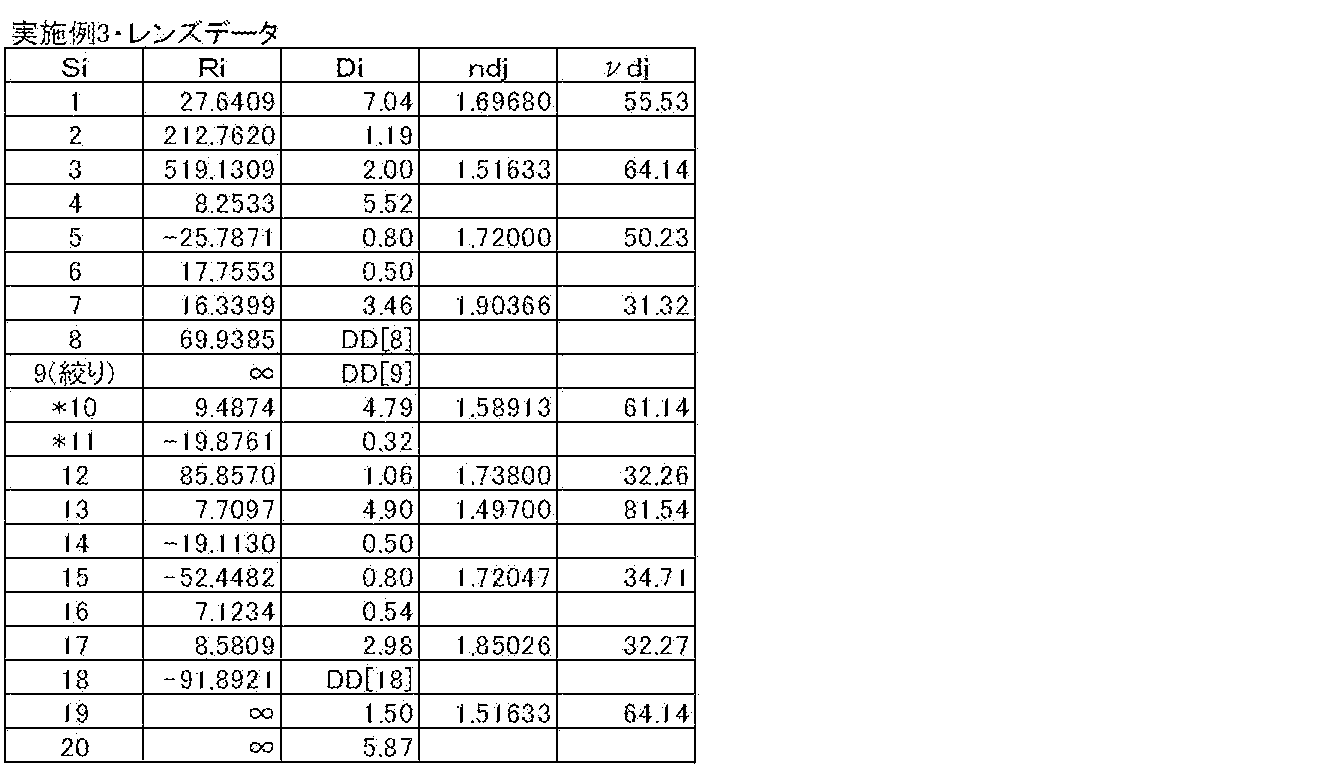
表1~表3は、図1に示した実施例1の撮像レンズの構成に対応する具体的なレンズデータを示している。表1にはその基本的なレンズデータを示し、表2にはその他のデータを示し、表3には非球面データを示す。表1に示したレンズデータにおける面番号Siの欄には、実施例1に係る変倍光学系について、最も物体側の構成要素の面を1番目として、像側に向かうに従い順次増加するようにして符号を付したi番目(i=1~20)の面の番号を示している。曲率半径Riの欄には、図1(B)において付した符号Riに対応させて、物体側からi番目の面の曲率半径の値(mm)を示す。面間隔Diの欄についても、同様に物体側からi番目の面Siとi+1番目の面Si+1との光軸上の間隔(mm)を示す。ndjの欄には、最も物体側のレンズを1番目として像側に向かうに従い順次増加するj番目(j=1、2、3、…)の光学要素のd線(波長587.6nm)に対する屈折率を示し、νdjの欄には、j番目の光学要素のd線に対するアッベ数を示す。表1のレンズデータにおいて、面番号の左側に付された記号「*」は、そのレンズ面が非球面形状であることを示す。表1の基本レンズデータには、これらの非球面の曲率半径として、近軸の曲率半径の数値を示している。
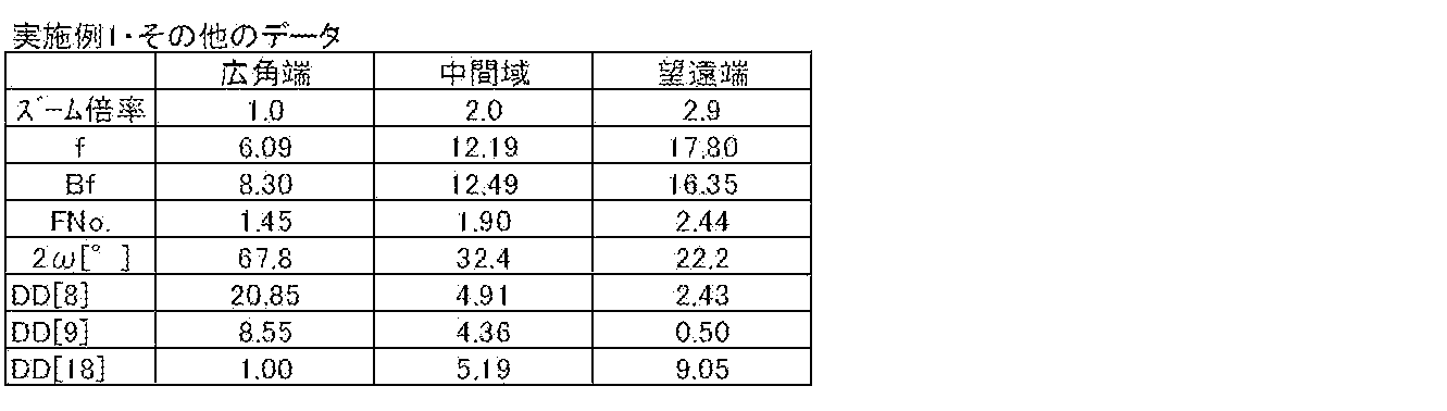
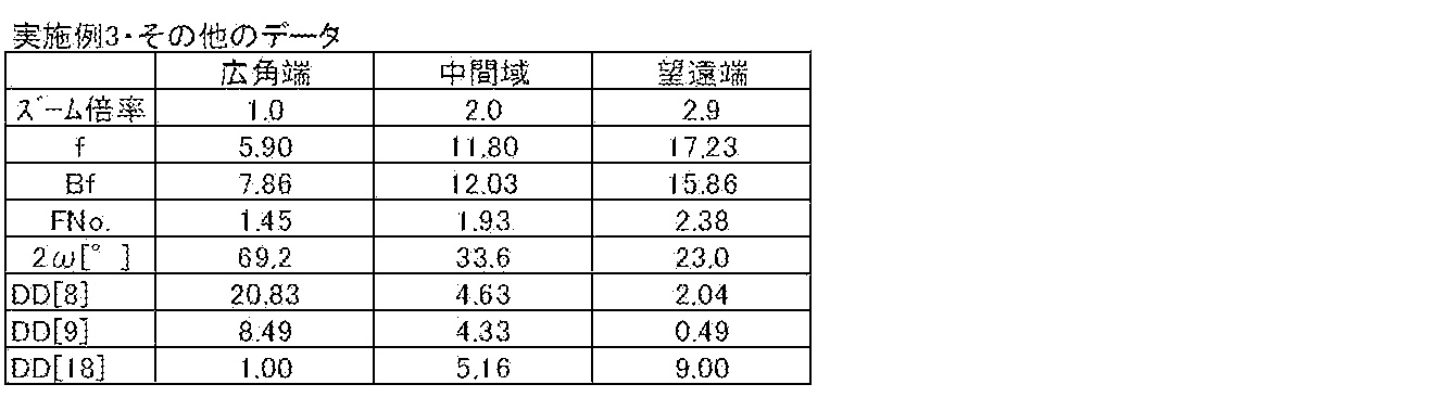
表2にはまた、その他のデータとして、広角端、中間域および望遠端での無限遠合焦状態における全系のズーム倍率、近軸焦点距離f(mm)、バックフォーカスBf、F値(FNo.)および画角(2ω)の値についても示す。
実施例1に係るズームレンズは、変倍に伴って第1レンズ群G1と第2レンズ群G2との間隔が変化するため、第1レンズ群G1と開口絞りStとの間隔D8、開口絞りStと第2レンズ群G2との間隔D9、および第2レンズ群と光学部材GCとの間隔D18は可変となっている。表2には、面間隔D8,D9,D18の変倍時のデータとして、広角端、中間域および望遠端での無限遠合焦状態におけるズーム間隔(mm)を示す。
表3には実施例1に係る変倍光学系の非球面データを示す。非球面データとして示した数値において、記号“E”は、その次に続く数値が10を底とした“べき指数”であることを示し、その10を底とした指数関数で表される数値が“E”の前の数値に乗算されることを示す。例えば、「1.0E-02」であれば、「1.0×10⁻²」であることを示す。なお非球面係数は、下記非球面式における各係数KA、Am(m=3、4、5、…16)の値である。
Zd=C・h2/{1+(1-KA・C2・h2)1/2}+ΣAm・hm
ただし、
Zd:非球面深さ(高さhの非球面上の点から、非球面頂点が接する光軸に垂直な平面に下ろした垂線の長さ)
h:高さ(光軸からのレンズ面までの距離)
C:近軸曲率半径の逆数
KA、Am:非球面係数(m=3、4、5、…16)
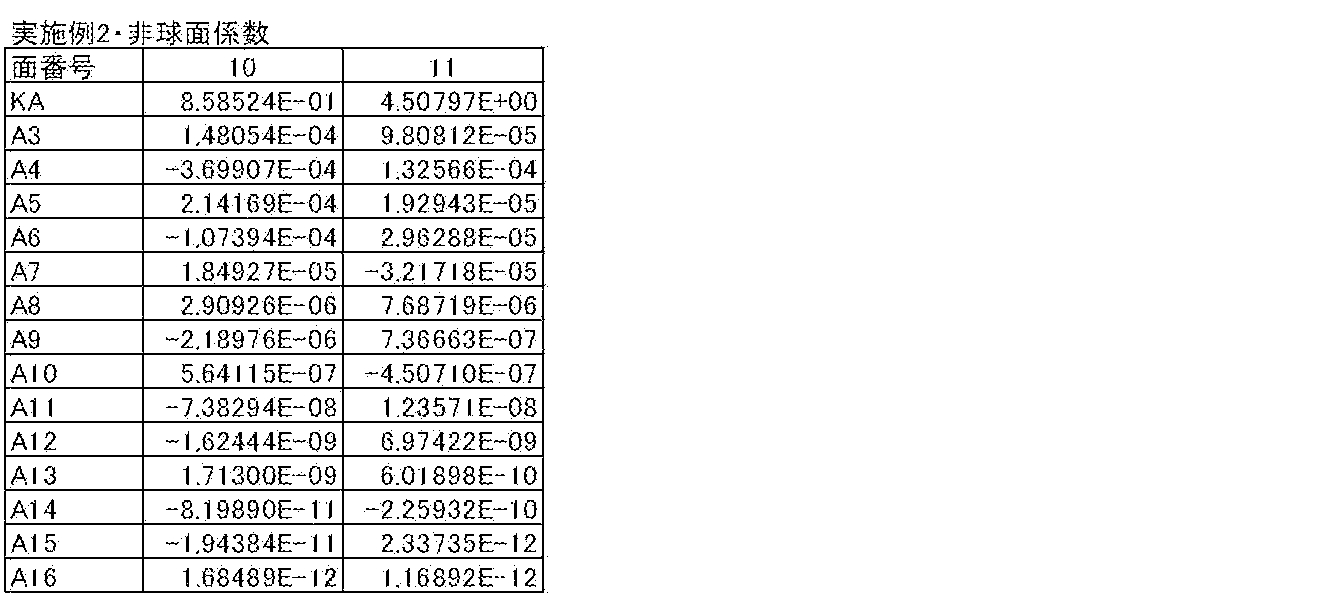
以上述べた表1~3の記載の仕方は、後述する表4~9においても同様である。
ただし、
Zd:非球面深さ(高さhの非球面上の点から、非球面頂点が接する光軸に垂直な平面に下ろした垂線の長さ)
h:高さ(光軸からのレンズ面までの距離)
C:近軸曲率半径の逆数
KA、Am:非球面係数(m=3、4、5、…16)
以上述べた表1~3の記載の仕方は、後述する表4~9においても同様である。
以下に記載する表では全て、上述したように長さの単位としてmmを用い、角度の単位として度(°)を用いているが、光学系は比例拡大または比例縮小して使用することが可能であるため、他の適当な単位を用いることもできる。
[実施例2,3]
図2(A),(B),(C)は、本発明の実施例2に係る変倍光学系の構成を示す図、図3(A),(B),(C)は、本発明の実施例3に係る変倍光学系の構成を示す図である。実施例2,3に係る変倍光学系は、実施例1に係る変倍光学系と略同様の構成とされている。
図2(A),(B),(C)は、本発明の実施例2に係る変倍光学系の構成を示す図、図3(A),(B),(C)は、本発明の実施例3に係る変倍光学系の構成を示す図である。実施例2,3に係る変倍光学系は、実施例1に係る変倍光学系と略同様の構成とされている。
上記の実施例1と同様に、実施例2に係る変倍光学系の具体的なレンズデータを表4~6に示す。また、実施例3に係る変倍光学系の具体的なレンズデータを表7~9に示す。




[各実施例のその他の数値データ]
表10には、上述の各条件式に関する値を、各実施例についてまとめたものを示す。表10から分かるように、条件式(1)~(8)については、各実施例の値がその数値範囲内となっている。
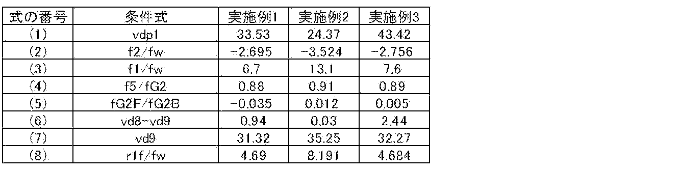
表10には、上述の各条件式に関する値を、各実施例についてまとめたものを示す。表10から分かるように、条件式(1)~(8)については、各実施例の値がその数値範囲内となっている。
[収差性能]
図4(A)~(E)はそれぞれ、実施例1に係る変倍光学系における広角端での球面収差、正弦条件違反量についての収差、非点収差、歪曲収差および倍率色収差を示している。図5(A)~(E)は中間域における同様の各収差を示し、図6(A)~(E)は、望遠端における同様の各収差を示している。各収差図には、d線(587.6nm)を基準波長とした収差を示す。球面収差図には、波長656.3nm(C線)、波長486.1nm(F線)、波長435.8nm(g線)および波長852.1nm(s線)についての収差も示す。非点収差図において、実線はサジタル方向、破線はタンジェンシャル方向の収差を示す。FNo.はF値、ωは半画角を示す。倍率色収差図には、C線、F線およびg線についての収差を示す。
図4(A)~(E)はそれぞれ、実施例1に係る変倍光学系における広角端での球面収差、正弦条件違反量についての収差、非点収差、歪曲収差および倍率色収差を示している。図5(A)~(E)は中間域における同様の各収差を示し、図6(A)~(E)は、望遠端における同様の各収差を示している。各収差図には、d線(587.6nm)を基準波長とした収差を示す。球面収差図には、波長656.3nm(C線)、波長486.1nm(F線)、波長435.8nm(g線)および波長852.1nm(s線)についての収差も示す。非点収差図において、実線はサジタル方向、破線はタンジェンシャル方向の収差を示す。FNo.はF値、ωは半画角を示す。倍率色収差図には、C線、F線およびg線についての収差を示す。
同様に、実施例2に係る変倍光学系についての諸収差を図7(A)~(E)(広角端)、図8(A)~(E)(中間域)および図9(A)~(E)(望遠端)に示す。同様にして、実施例3に係る変倍光学系についての諸収差を図10~12の(A)~(E)に示す。
以上の各数値データおよび各収差図から分かるように、各実施例について諸収差が良好に補正され、全体的に小型化の図られた変倍光学系が実現できている。
なお、本発明は、上記実施形態および各実施例に限定されず種々の変形実施が可能である。例えば、各レンズ成分の曲率半径、面間隔および屈折率の値等は、上記各数値実施例で示した値に限定されず、他の値をとり得る。
Claims (14)
- 物体側から順に、負の屈折力を有する第1レンズ群、絞り、および正の屈折力を有する第2レンズ群からなり、広角端から望遠端へ変倍する際に、前記第1レンズ群と前記第2レンズ群との光軸方向の間隔が小さくなるように構成された変倍光学系であって、
前記絞りが、変倍時に像面に対して固定されており、
前記第1レンズ群が、物体側から順に、正レンズ、負レンズ、負レンズ、および物体側に凸面を向けた正メニスカスレンズからなり
下記条件式(1)、(2)を満足することを特徴とする変倍光学系。
22<νdp<47 … (1)
-5.00<f2/fw<-1.20 … (2)
ただし、
νdp:前記第1レンズ群の最も物体側の正レンズおよび最も像側の正メニスカスレンズのd線における平均アッベ数
fw:広角端における全系の焦点距離
f2:前記第1レンズ群の物体側から2番目に配置された負レンズの焦点距離 - 下記条件式(1-1)を満足することを特徴とする請求項1記載の変倍光学系。
24<νdp<44 … (1-1)
ただし、
νdp:前記第1レンズ群の最も物体側の正レンズおよび最も像側の正メニスカスレンズのd線における平均アッベ数 - 下記条件式(2-1)を満足することを特徴とする請求項1または2記載の変倍光学系。
-4.00<f2/fw<-2.00 … (2-1)
ただし、
fw:広角端における全系の焦点距離
f2:前記第1レンズ群の物体側から2番目に配置された負レンズの焦点距離 - 下記条件式(3)を満足することを特徴とする請求項1から3のいずれか1項記載の変倍光学系。
3<f1/fw<17 … (3)
ただし、
f1:前記第1レンズ群の最も物体側の正レンズの焦点距離
fw:広角端における全系の焦点距離 - 下記条件式(3-1)を満足することを特徴とする請求項1から3のいずれか1項記載の変倍光学系。
6<f1/fw<14 … (3-1)
ただし、
f1:前記第1レンズ群の最も物体側の正レンズの焦点距離
fw:広角端における全系の焦点距離 - 前記第2レンズ群が、物体側から順に、両凸レンズ、負レンズ、両凸レンズ、負レンズ、および正レンズからなることを特徴とする請求項1から5のいずれか1項記載の変倍光学系。
- 下記条件式(4)を満足することを特徴とする請求項6記載の変倍光学系。
0.3<f5/fG2<1.5 … (4)
ただし、
f5:前記第2レンズ群の最も物体側の両凸レンズの焦点距離
fG2:前記第2レンズ群の焦点距離 - 下記条件式(4-1)を満足することを特徴とする請求項6記載の変倍光学系。
0.6<f5/fG2<1.2 … (4-1)
ただし、
f5:前記第2レンズ群の最も物体側の両凸レンズの焦点距離
fG2:前記第2レンズ群の焦点距離 - 下記条件式(5)~(7)を満足することを特徴とする請求項6から8のいずれか1項記載の変倍光学系。
-0.1<fG2F/fG2B<0.1 … (5)
-5<νd8-νd9<10 … (6)
29<νd9<37 … (7)
ただし、
fG2F:前記第2レンズ群の物体側の3枚のレンズの合成焦点距離
fG2B:前記第2レンズ群の像側の2枚のレンズの合成焦点距離
νd8:前記第2レンズ群の像側から2番目の負レンズのd線におけるアッベ数
νd9:前記第2レンズ群の正レンズのd線におけるアッベ数 - 下記条件式(5-1)を満足することを特徴とする請求項9記載の変倍光学系。
-0.05<fG2F/fG2B<0.05 … (5-1)
ただし、
fG2F:前記第2レンズ群の物体側の3枚のレンズの合成焦点距離
fG2B:前記第2レンズ群の像側の2枚のレンズの合成焦点距離 - 下記条件式(6-1)を満足することを特徴とする請求項9または10項記載の変倍光学系。
0<νd8-νd9<5 … (6-1)
ただし、
νd8:前記第2レンズ群の像側から2番目の負レンズのd線におけるアッベ数
νd9:前記第2レンズ群の最も像側の正レンズのd線におけるアッベ数 - 下記条件式(7-1)を満足することを特徴とする請求項9から11のいずれか1項記載の変倍光学系。
31<νd9<36 … (7-1)
ただし、
νd9:前記第2レンズ群の正レンズのd線におけるアッベ数 - 前記第1レンズ群の最も物体側の正レンズが、物体側に凸面を向けた正メニスカスレンズからなり、
下記条件式(8)を満足することを特徴とする請求項1から12のいずれか1項記載の変倍光学系。
4<r1f/fw<9 … (8)
ただし、
r1f:前記第1レンズ群の最も物体側の正レンズの物体側の面の曲率半径
fw:広角端における全系の焦点距離 - 請求項1から13のいずれか1項記載の変倍光学系を搭載したことを特徴とする撮像装置。
Priority Applications (3)
| Application Number | Priority Date | Filing Date | Title |
|---|---|---|---|
| JP2014511105A JP5680794B2 (ja) | 2012-04-18 | 2013-04-16 | 変倍光学系および撮像装置 |
| CN201380020137.7A CN104246575B (zh) | 2012-04-18 | 2013-04-16 | 变倍光学系统和摄像装置 |
| US14/513,416 US9128275B2 (en) | 2012-04-18 | 2014-10-14 | Variable magnification optical system and imaging apparatus |
Applications Claiming Priority (2)
| Application Number | Priority Date | Filing Date | Title |
|---|---|---|---|
| JP2012094604 | 2012-04-18 | ||
| JP2012-094604 | 2012-04-18 |
Related Child Applications (1)
| Application Number | Title | Priority Date | Filing Date |
|---|---|---|---|
| US14/513,416 Continuation US9128275B2 (en) | 2012-04-18 | 2014-10-14 | Variable magnification optical system and imaging apparatus |
Publications (1)
| Publication Number | Publication Date |
|---|---|
| WO2013157248A1 true WO2013157248A1 (ja) | 2013-10-24 |
Family
ID=49383219
Family Applications (1)
| Application Number | Title | Priority Date | Filing Date |
|---|---|---|---|
| PCT/JP2013/002559 Ceased WO2013157248A1 (ja) | 2012-04-18 | 2013-04-16 | 変倍光学系および撮像装置 |
Country Status (4)
| Country | Link |
|---|---|
| US (1) | US9128275B2 (ja) |
| JP (1) | JP5680794B2 (ja) |
| CN (1) | CN104246575B (ja) |
| WO (1) | WO2013157248A1 (ja) |
Cited By (1)
| Publication number | Priority date | Publication date | Assignee | Title |
|---|---|---|---|---|
| CN115427863A (zh) * | 2020-03-30 | 2022-12-02 | Lg 伊诺特有限公司 | 光学系统和包括该光学系统的相机模块 |
Families Citing this family (3)
| Publication number | Priority date | Publication date | Assignee | Title |
|---|---|---|---|---|
| CN105527695B (zh) * | 2016-01-20 | 2018-11-20 | 北京疯景科技有限公司 | 一种镜头和成像装置 |
| JP7805830B2 (ja) * | 2022-03-17 | 2026-01-26 | キヤノン株式会社 | 光学系及びそれを備える撮像装置 |
| CN115494630A (zh) * | 2022-09-21 | 2022-12-20 | 协益电子(苏州)有限公司 | 一种变焦机器视觉镜头 |
Citations (3)
| Publication number | Priority date | Publication date | Assignee | Title |
|---|---|---|---|---|
| JPH10206734A (ja) * | 1997-01-17 | 1998-08-07 | Asahi Optical Co Ltd | ズームレンズ |
| JPH11223768A (ja) * | 1998-02-05 | 1999-08-17 | Asahi Optical Co Ltd | ズームレンズ系 |
| JPH11305125A (ja) * | 1998-02-19 | 1999-11-05 | Canon Inc | ズ―ムレンズ及びそれを用いた撮影装置 |
Family Cites Families (8)
| Publication number | Priority date | Publication date | Assignee | Title |
|---|---|---|---|---|
| JPH10305125A (ja) * | 1996-04-05 | 1998-11-17 | Shinichi Suzuki | ゴルフスイング矯正装置 |
| JP3306360B2 (ja) | 1997-11-26 | 2002-07-24 | 旭光学工業株式会社 | ズームレンズ系 |
| US6934092B1 (en) | 1998-02-19 | 2005-08-23 | Canon Kabushiki Kaisha | Zoom lens and photographing apparatus having the same |
| JP2000035537A (ja) | 1998-05-12 | 2000-02-02 | Asahi Optical Co Ltd | 2群ズ―ムレンズ系 |
| JP2001330773A (ja) | 2000-05-23 | 2001-11-30 | Kyocera Corp | ズームレンズ |
| US6618210B2 (en) * | 2000-07-07 | 2003-09-09 | Olympus Optical Co., Ltd. | Zoom lens system and image pickup apparatus having the same |
| JP4851146B2 (ja) | 2005-09-14 | 2012-01-11 | 富士フイルム株式会社 | 2群ズーム投影レンズおよび投写型表示装置 |
| CN101525545A (zh) * | 2009-04-13 | 2009-09-09 | 北京海润川投资咨询有限公司 | 工业化连续的农林生物质快速热解炼油方法及其装置 |
-
2013
- 2013-04-16 WO PCT/JP2013/002559 patent/WO2013157248A1/ja not_active Ceased
- 2013-04-16 CN CN201380020137.7A patent/CN104246575B/zh not_active Expired - Fee Related
- 2013-04-16 JP JP2014511105A patent/JP5680794B2/ja not_active Expired - Fee Related
-
2014
- 2014-10-14 US US14/513,416 patent/US9128275B2/en not_active Expired - Fee Related
Patent Citations (3)
| Publication number | Priority date | Publication date | Assignee | Title |
|---|---|---|---|---|
| JPH10206734A (ja) * | 1997-01-17 | 1998-08-07 | Asahi Optical Co Ltd | ズームレンズ |
| JPH11223768A (ja) * | 1998-02-05 | 1999-08-17 | Asahi Optical Co Ltd | ズームレンズ系 |
| JPH11305125A (ja) * | 1998-02-19 | 1999-11-05 | Canon Inc | ズ―ムレンズ及びそれを用いた撮影装置 |
Cited By (1)
| Publication number | Priority date | Publication date | Assignee | Title |
|---|---|---|---|---|
| CN115427863A (zh) * | 2020-03-30 | 2022-12-02 | Lg 伊诺特有限公司 | 光学系统和包括该光学系统的相机模块 |
Also Published As
| Publication number | Publication date |
|---|---|
| CN104246575A (zh) | 2014-12-24 |
| JP5680794B2 (ja) | 2015-03-04 |
| JPWO2013157248A1 (ja) | 2015-12-21 |
| US9128275B2 (en) | 2015-09-08 |
| CN104246575B (zh) | 2016-09-07 |
| US20150029597A1 (en) | 2015-01-29 |
Similar Documents
| Publication | Publication Date | Title |
|---|---|---|
| JP5671190B2 (ja) | 撮像レンズおよび撮像装置 | |
| JP5663116B2 (ja) | ズームレンズおよび撮像装置 | |
| JP5698342B2 (ja) | 変倍光学系および撮像装置 | |
| US9405095B2 (en) | Imaging lens and imaging apparatus | |
| JP6128387B2 (ja) | ズームレンズおよび撮像装置 | |
| JP5253997B2 (ja) | 変倍光学系および撮像装置 | |
| JP6356622B2 (ja) | ズームレンズおよび撮像装置 | |
| JP6204852B2 (ja) | ズームレンズおよび撮像装置 | |
| US9377607B2 (en) | Zoom lens and imaging apparatus | |
| US9568715B2 (en) | Zoom lens and imaging apparatus | |
| CN104583836B (zh) | 变焦透镜和摄像装置 | |
| US9256053B2 (en) | Imaging lens and imaging apparatus including the imaging lens | |
| JP6284893B2 (ja) | ズームレンズおよび撮像装置 | |
| CN103797395B (zh) | 可变放大倍率光学系统和成像设备 | |
| US9726867B2 (en) | Variable magnification optical system and imaging apparatus | |
| JP5860565B2 (ja) | ズームレンズおよび撮像装置 | |
| WO2013099213A1 (ja) | 撮像レンズおよび撮像装置 | |
| US9235035B2 (en) | Zoom lens and imaging apparatus | |
| CN108279489B (zh) | 变焦镜头及摄像装置 | |
| CN108885333A (zh) | 变焦透镜及摄像装置 | |
| JP5680794B2 (ja) | 変倍光学系および撮像装置 | |
| US10268028B2 (en) | Zoom lens and imaging apparatus | |
| WO2013031187A1 (ja) | ズームレンズおよび撮像装置 | |
| WO2013031186A1 (ja) | ズームレンズおよび撮像装置 | |
| WO2013031181A1 (ja) | ズームレンズおよび撮像装置 |
Legal Events
| Date | Code | Title | Description |
|---|---|---|---|
| 121 | Ep: the epo has been informed by wipo that ep was designated in this application |
Ref document number: 13778018 Country of ref document: EP Kind code of ref document: A1 |
|
| ENP | Entry into the national phase |
Ref document number: 2014511105 Country of ref document: JP Kind code of ref document: A |
|
| NENP | Non-entry into the national phase |
Ref country code: DE |
|
| 122 | Ep: pct application non-entry in european phase |
Ref document number: 13778018 Country of ref document: EP Kind code of ref document: A1 |