WO2013153887A1 - 無線通信装置、情報処理装置および通信方法 - Google Patents
無線通信装置、情報処理装置および通信方法 Download PDFInfo
- Publication number
- WO2013153887A1 WO2013153887A1 PCT/JP2013/056323 JP2013056323W WO2013153887A1 WO 2013153887 A1 WO2013153887 A1 WO 2013153887A1 JP 2013056323 W JP2013056323 W JP 2013056323W WO 2013153887 A1 WO2013153887 A1 WO 2013153887A1
- Authority
- WO
- WIPO (PCT)
- Prior art keywords
- wireless communication
- information
- communication device
- application
- action frame
- Prior art date
Links
Images


Classifications
-
- H—ELECTRICITY
- H04—ELECTRIC COMMUNICATION TECHNIQUE
- H04W—WIRELESS COMMUNICATION NETWORKS
- H04W8/00—Network data management
-
- H—ELECTRICITY
- H04—ELECTRIC COMMUNICATION TECHNIQUE
- H04W—WIRELESS COMMUNICATION NETWORKS
- H04W88/00—Devices specially adapted for wireless communication networks, e.g. terminals, base stations or access point devices
- H04W88/02—Terminal devices
-
- H—ELECTRICITY
- H04—ELECTRIC COMMUNICATION TECHNIQUE
- H04L—TRANSMISSION OF DIGITAL INFORMATION, e.g. TELEGRAPHIC COMMUNICATION
- H04L63/00—Network architectures or network communication protocols for network security
- H04L63/04—Network architectures or network communication protocols for network security for providing a confidential data exchange among entities communicating through data packet networks
- H04L63/0428—Network architectures or network communication protocols for network security for providing a confidential data exchange among entities communicating through data packet networks wherein the data content is protected, e.g. by encrypting or encapsulating the payload
-
- H—ELECTRICITY
- H04—ELECTRIC COMMUNICATION TECHNIQUE
- H04L—TRANSMISSION OF DIGITAL INFORMATION, e.g. TELEGRAPHIC COMMUNICATION
- H04L67/00—Network arrangements or protocols for supporting network services or applications
- H04L67/01—Protocols
- H04L67/10—Protocols in which an application is distributed across nodes in the network
- H04L67/104—Peer-to-peer [P2P] networks
-
- H—ELECTRICITY
- H04—ELECTRIC COMMUNICATION TECHNIQUE
- H04L—TRANSMISSION OF DIGITAL INFORMATION, e.g. TELEGRAPHIC COMMUNICATION
- H04L67/00—Network arrangements or protocols for supporting network services or applications
- H04L67/01—Protocols
- H04L67/12—Protocols specially adapted for proprietary or special-purpose networking environments, e.g. medical networks, sensor networks, networks in vehicles or remote metering networks
- H04L67/125—Protocols specially adapted for proprietary or special-purpose networking environments, e.g. medical networks, sensor networks, networks in vehicles or remote metering networks involving control of end-device applications over a network
-
- H—ELECTRICITY
- H04—ELECTRIC COMMUNICATION TECHNIQUE
- H04L—TRANSMISSION OF DIGITAL INFORMATION, e.g. TELEGRAPHIC COMMUNICATION
- H04L67/00—Network arrangements or protocols for supporting network services or applications
- H04L67/50—Network services
- H04L67/51—Discovery or management thereof, e.g. service location protocol [SLP] or web services
-
- H—ELECTRICITY
- H04—ELECTRIC COMMUNICATION TECHNIQUE
- H04L—TRANSMISSION OF DIGITAL INFORMATION, e.g. TELEGRAPHIC COMMUNICATION
- H04L69/00—Network arrangements, protocols or services independent of the application payload and not provided for in the other groups of this subclass
- H04L69/30—Definitions, standards or architectural aspects of layered protocol stacks
- H04L69/32—Architecture of open systems interconnection [OSI] 7-layer type protocol stacks, e.g. the interfaces between the data link level and the physical level
- H04L69/321—Interlayer communication protocols or service data unit [SDU] definitions; Interfaces between layers
-
- H—ELECTRICITY
- H04—ELECTRIC COMMUNICATION TECHNIQUE
- H04M—TELEPHONIC COMMUNICATION
- H04M1/00—Substation equipment, e.g. for use by subscribers
- H04M1/72—Mobile telephones; Cordless telephones, i.e. devices for establishing wireless links to base stations without route selection
- H04M1/724—User interfaces specially adapted for cordless or mobile telephones
- H04M1/72403—User interfaces specially adapted for cordless or mobile telephones with means for local support of applications that increase the functionality
- H04M1/72409—User interfaces specially adapted for cordless or mobile telephones with means for local support of applications that increase the functionality by interfacing with external accessories
- H04M1/72412—User interfaces specially adapted for cordless or mobile telephones with means for local support of applications that increase the functionality by interfacing with external accessories using two-way short-range wireless interfaces
-
- H—ELECTRICITY
- H04—ELECTRIC COMMUNICATION TECHNIQUE
- H04W—WIRELESS COMMUNICATION NETWORKS
- H04W4/00—Services specially adapted for wireless communication networks; Facilities therefor
- H04W4/20—Services signaling; Auxiliary data signalling, i.e. transmitting data via a non-traffic channel
- H04W4/21—Services signaling; Auxiliary data signalling, i.e. transmitting data via a non-traffic channel for social networking applications
-
- H—ELECTRICITY
- H04—ELECTRIC COMMUNICATION TECHNIQUE
- H04W—WIRELESS COMMUNICATION NETWORKS
- H04W52/00—Power management, e.g. TPC [Transmission Power Control], power saving or power classes
- H04W52/02—Power saving arrangements
- H04W52/0209—Power saving arrangements in terminal devices
- H04W52/0225—Power saving arrangements in terminal devices using monitoring of external events, e.g. the presence of a signal
- H04W52/0229—Power saving arrangements in terminal devices using monitoring of external events, e.g. the presence of a signal where the received signal is a wanted signal
-
- H—ELECTRICITY
- H04—ELECTRIC COMMUNICATION TECHNIQUE
- H04W—WIRELESS COMMUNICATION NETWORKS
- H04W52/00—Power management, e.g. TPC [Transmission Power Control], power saving or power classes
- H04W52/02—Power saving arrangements
- H04W52/0209—Power saving arrangements in terminal devices
- H04W52/0261—Power saving arrangements in terminal devices managing power supply demand, e.g. depending on battery level
- H04W52/0287—Power saving arrangements in terminal devices managing power supply demand, e.g. depending on battery level changing the clock frequency of a controller in the equipment
-
- H—ELECTRICITY
- H04—ELECTRIC COMMUNICATION TECHNIQUE
- H04W—WIRELESS COMMUNICATION NETWORKS
- H04W76/00—Connection management
- H04W76/10—Connection setup
- H04W76/14—Direct-mode setup
-
- H—ELECTRICITY
- H04—ELECTRIC COMMUNICATION TECHNIQUE
- H04W—WIRELESS COMMUNICATION NETWORKS
- H04W8/00—Network data management
- H04W8/005—Discovery of network devices, e.g. terminals
-
- H—ELECTRICITY
- H04—ELECTRIC COMMUNICATION TECHNIQUE
- H04M—TELEPHONIC COMMUNICATION
- H04M2250/00—Details of telephonic subscriber devices
- H04M2250/06—Details of telephonic subscriber devices including a wireless LAN interface
-
- H—ELECTRICITY
- H04—ELECTRIC COMMUNICATION TECHNIQUE
- H04W—WIRELESS COMMUNICATION NETWORKS
- H04W4/00—Services specially adapted for wireless communication networks; Facilities therefor
- H04W4/80—Services using short range communication, e.g. near-field communication [NFC], radio-frequency identification [RFID] or low energy communication
-
- H—ELECTRICITY
- H04—ELECTRIC COMMUNICATION TECHNIQUE
- H04W—WIRELESS COMMUNICATION NETWORKS
- H04W76/00—Connection management
- H04W76/20—Manipulation of established connections
- H04W76/22—Manipulation of transport tunnels
-
- H—ELECTRICITY
- H04—ELECTRIC COMMUNICATION TECHNIQUE
- H04W—WIRELESS COMMUNICATION NETWORKS
- H04W84/00—Network topologies
- H04W84/02—Hierarchically pre-organised networks, e.g. paging networks, cellular networks, WLAN [Wireless Local Area Network] or WLL [Wireless Local Loop]
- H04W84/10—Small scale networks; Flat hierarchical networks
- H04W84/12—WLAN [Wireless Local Area Networks]
-
- Y—GENERAL TAGGING OF NEW TECHNOLOGICAL DEVELOPMENTS; GENERAL TAGGING OF CROSS-SECTIONAL TECHNOLOGIES SPANNING OVER SEVERAL SECTIONS OF THE IPC; TECHNICAL SUBJECTS COVERED BY FORMER USPC CROSS-REFERENCE ART COLLECTIONS [XRACs] AND DIGESTS
- Y02—TECHNOLOGIES OR APPLICATIONS FOR MITIGATION OR ADAPTATION AGAINST CLIMATE CHANGE
- Y02D—CLIMATE CHANGE MITIGATION TECHNOLOGIES IN INFORMATION AND COMMUNICATION TECHNOLOGIES [ICT], I.E. INFORMATION AND COMMUNICATION TECHNOLOGIES AIMING AT THE REDUCTION OF THEIR OWN ENERGY USE
- Y02D30/00—Reducing energy consumption in communication networks
- Y02D30/70—Reducing energy consumption in communication networks in wireless communication networks
Definitions
- This technology relates to a wireless communication device. Specifically, the present invention relates to a wireless communication apparatus, an information processing apparatus, and a communication method that exchange various information using wireless communication.
- wireless communication devices that perform wireless communication using a wireless LAN (Local Area Network) have become widespread.
- a wireless LAN represented by IEEE (Institute of Electrical and Electronics Electronics) 802.11 is widely used.
- a plurality of wireless communication devices are connected wirelessly and various applications are executed between these wireless communication devices.
- an application is designated by a user operation before or after establishment of a wireless connection.
- This technology has been created in view of such a situation, and aims to easily use an application desired by a user.
- the present technology has been made to solve the above-described problems.
- the first aspect of the present technology is wireless communication that performs inter-device wireless communication with other wireless communication devices in accordance with Wi-Fi (Wireless Fidelity) Direct specifications.
- a wireless communication apparatus comprising a transmission unit that includes information related to the role of the wireless communication apparatus in an action frame defined in IEEE (Institute of Electrical and Electronic Engineers) 802.11 specification and a communication method thereof And a program for causing a computer to execute the method. Accordingly, there is an effect of performing inter-device wireless communication with another wireless communication device according to the Wi-Fi Direct specification, and transmitting information regarding the role of the wireless communication device included in the action frame defined in the IEEE 802.11 specification.
- the transmission unit may perform the transmission when connected to the other wireless communication device by P2P (Peer to Peer). This brings about the effect
- P2P Peer to Peer
- the information regarding the role of the wireless communication device may be information regarding a source or a sink compliant with the Wi-Fi Display specification.
- the information about the source or sink compliant with the Wi-Fi Display specification is included in the action frame defined in the IEEE 802.11 specification and transmitted.
- the action frame may be a vendor specific action frame defined in the IEEE 802.11 specification.
- information regarding the role of the wireless communication device may be included in the area of the vendor specific content in the vendor specific action frame.
- a type information part and an information element part may be provided in the action frame. This brings about the effect
- the transmission unit may include information on the fourth layer in the action frame and transmit the information. This brings about the effect that information about the fourth layer is included in the action frame and transmitted.
- the information related to the fourth layer may include at least information related to RTSP. This brings about the effect
- the information on the fourth layer may include at least information on a port number used for the RTSP. This brings about the effect
- the information regarding the role of the wireless communication device and the information regarding the fourth layer are arranged in the order of the information regarding the role of the wireless communication device and the information regarding the fourth layer in the action frame. You may do it. This brings about the effect
- the transmitting unit may transmit capability information included in the action frame.
- the capability information is transmitted by including it in the action frame.
- the capability information may include at least information regarding whether or not the content protection conforms to the Wi-Fi Display specification.
- the second aspect of the present technology provides the connection discovery based on a communication unit that performs inter-device wireless communication with another device discovered by the connection discovery process, and a timing at which the connection of the inter-device wireless communication is established.
- a control unit that operates the first application specified in the process, and the communication unit executes the second application when the second application is executed while the first application is operating.
- a wireless communication device that transmits information about an application in an action frame defined in the IEEE 802.11 specification, a communication method thereof, and a program that causes a computer to execute the method.
- inter-device wireless communication is performed with another device discovered by the connection discovery process, and the first application specified in the connection discovery process is operated based on the timing when the connection of the inter-device wireless communication is established.
- information related to the second application is included in an action frame defined in the IEEE 802.11 specification and transmitted.
- control unit may end the first application based on a timing at which the operation of the second application starts. This brings about the effect
- control unit may suppress the amount of data communication related to the first application based on a timing at which the operation of the second application starts. This brings about the effect
- control unit may check the operation status of the first application periodically or irregularly after the operation of the second application is started. This brings about the effect that the operation status of the first application is confirmed regularly or irregularly after the operation of the second application is started.
- the second application may be Wi-Fi CERTIFIED Miracast.
- information regarding Wi-Fi CERTIFIED Miracast is included in the action frame defined in the IEEE 802.11 specification and transmitted.
- the first application may be DLNA (Digital Living Network Alliance). This brings about the effect
- DLNA Digital Living Network Alliance
- the communication unit may transmit a FIN packet (finish packet) on a TCP (Transmission Control Protocol) based on the timing when the operation of the second application starts. Good. This brings about the effect that the FIN packet is transmitted over TCP based on the timing when the operation of the second application starts.
- a FIN packet finish packet
- TCP Transmission Control Protocol
- a third aspect of the present technology is a wireless communication device that performs inter-device wireless communication with another wireless communication device according to Wi-Fi (Wireless Fidelity) Direct specifications, and includes information on the role of the wireless communication device according to IEEE. (Institute of Electrical and Electronic Engineers) Transmitter included in action frame defined in 802.11 specification, display unit for displaying image data, and protocol switching unit for switching the protocol using wireless communication between devices And a communication method thereof, and a program for causing a computer to execute the method.
- Wi-Fi Wireless Fidelity
- IEEE Institute of Electrical and Electronic Engineers
- an operation receiving unit that receives a user operation is further provided, and the transmission unit receives a user operation reception timing for starting communication of image data received by the operation receiving unit. Based on this, information regarding the role of the wireless communication device may be transmitted. Accordingly, there is an effect that information regarding the role of the wireless communication device is transmitted based on the reception timing of the user operation (user operation for starting communication of image data) received by the operation reception unit.
- the transmission unit may transmit the image data displayed on the display unit using the protocol switched by the protocol switching unit. This brings about the effect
- a fourth aspect of the present technology includes a processor and a memory that stores a program to be executed by the processor, and the program performs wireless communication between other devices in accordance with Wi-Fi Direct specifications.
- Information processing apparatus for causing the processor to execute one procedure and a second procedure for transmitting information including a role of a wireless communication apparatus in which the information processing apparatus is used in an action frame defined in the IEEE 802.11 specification, and the information A processing method and a program for causing a computer to execute the method.
- wireless communication between other devices is performed according to the Wi-Fi Direct specification, and information regarding the role of the wireless communication device used by the information processing device is included in the action frame defined in the IEEE 802.11 specification and transmitted. Bring about an effect.
- the program may further cause the processor to execute a procedure for performing signal processing for processing image data. This brings about the effect
- the program may further cause the processor to execute a procedure for adjusting power consumption according to the operation of the processor. As a result, the power consumption is adjusted according to the operation of the processor.
- FIG. 10 It is a figure showing an example of composition of communications system 10 in a 1st embodiment of this art. It is a block diagram which shows the function structural example of the 1st radio
- 6 is a flowchart illustrating an example of a processing procedure of communication processing by the first wireless communication device 100 according to the first embodiment of the present technology.
- 6 is a flowchart illustrating an example of a processing procedure of communication processing by the first wireless communication device 100 according to the first embodiment of the present technology.
- 6 is a flowchart illustrating an example of a processing procedure of communication processing by the first wireless communication device 100 according to the first embodiment of the present technology.
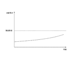
- It is a block diagram showing an example of composition of information processor 800 in a 2nd embodiment of this art. It is a figure showing an example of relation between performance and power consumption of information processor 800 in a 2nd embodiment of this art.
- First embodiment communication control: an example in which a specific application used after connection at the second layer is specified without disconnecting the connection at the second layer
- Second embodiment communication control: an example of an information processing device used in a wireless communication device
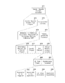
- FIG. 1 is a diagram illustrating a configuration example of a communication system 10 according to the first embodiment of the present technology.
- the communication system 10 includes a first wireless communication device 100, a second wireless communication device 200, a third wireless communication device 300, and a fourth wireless communication device 400.
- the first wireless communication device 100, the second wireless communication device 200, the third wireless communication device 300, and the fourth wireless communication device 400 have a wireless communication function, and connect to each other using wireless communication to transmit and receive various information.
- a wireless communication device capable of Each of these wireless communication devices is a wireless communication device compliant with the IEEE (Institute of Electrical and Electronics Electronics) 802.11 specification that enables P2P (Peer to Peer) connection. That is, each of these wireless communication devices forms a communication group and can directly communicate without going through an access point (not shown). In this case, which wireless communication device operates as a parent device and which wireless communication device device operates as a child device may be determined at the time of manufacture of each wireless communication device, or determined at the time of manufacture. It does not have to be.
- the first wireless communication device 100 and the second wireless communication device 200 form a communication group, the first wireless communication device 100 directly transmits data (for example, moving image content) to the second wireless communication device 200. be able to.
- the video content stored in the first wireless communication device 100 can be displayed on the second wireless communication device 200 by connecting to each other using wireless communication.
- Wi-Fi Direct Direct is known as an example of a communication standard for direct communication between wireless communication devices.
- the first wireless communication device 100 is, for example, a mobile phone device (for example, a wireless communication device having a call function and a data communication function).
- the second wireless communication device 200 is, for example, a video viewing device (for example, a hard disk built-in television) that records or displays moving image content.
- the third wireless communication apparatus 300 is, for example, an information processing apparatus (for example, a notebook PC (Personal Computer)) that performs various types of information processing.
- the fourth wireless communication device 400 is, for example, a portable information processing device (for example, a smartphone having a call function and a data communication function).
- the first wireless communication device 100, the second wireless communication device 200, the third wireless communication device 300, and the fourth wireless communication device 400 connect to an access point (not shown) using wireless communication and various information. Can be sent and received.
- the access point is an access point corresponding to a wireless LAN system such as IEEE802.11a / b / g / n, for example. That is, a wireless LAN standardized by IEEE802.11a / b / g / n is realized by a router and an access point (for example, a product incorporating an access point in the router).
- Data communicated between a plurality of wireless communication devices includes, for example, music data such as music and radio programs, movies, television programs, video programs, pictures, documents, pictures, image data such as diagrams, game data, and the like Data such as software.
- the wireless communication apparatus shown in FIG. 1 is an example, and the present invention can be applied to other wireless communication apparatuses.
- the present invention may be applied to an imaging device (for example, a digital still camera, a digital video camera (for example, a camera-integrated recorder)) having a wireless communication function, and an audio output device (for example, a portable music player) having a wireless communication function.
- an imaging device for example, a digital still camera, a digital video camera (for example, a camera-integrated recorder)
- an audio output device for example, a portable music player
- the present invention can be applied to a display device (for example, a digital photo frame) having a wireless communication function and an electronic book display device having a wireless communication function.
- the present invention can be applied to other information processing apparatuses having a wireless communication function.
- Information processing devices having a wireless communication function include, for example, home video processing devices (DVD recorders, VCRs, etc.), PDAs (Personal Digital Assistants), home game devices, home appliances, portable video processing devices, and portable games. Equipment.
- the present invention can also be applied to an information processing apparatus (for example, a personal computer that does not have a wireless communication function) capable of performing wireless communication by mounting a wireless communication device having a wireless communication function.
- FIG. 2 is a block diagram illustrating a functional configuration example of the first wireless communication device 100 according to the first embodiment of the present technology.
- the functional configurations (functional configurations related to wireless communication) of the second wireless communication device 200, the third wireless communication device 300, and the fourth wireless communication device 400 are substantially the same as those of the first wireless communication device 100. The description of is omitted. In the following description, each part of each wireless communication device other than the first wireless communication device 100 will be described using the same reference numerals as those of the first wireless communication device 100.
- the first wireless communication apparatus 100 includes an antenna 101, a data processing unit 110, a transmission processing unit 120, a wireless interface unit 130, a control unit 140, a memory 150, an operation reception unit 160, and a display unit 170. Prepare.
- the data processing unit 110 processes various data based on the control of the control unit 140. For example, when performing a transmission operation, the data processing unit 110 creates various data frames and data packets in response to a request from an upper layer and supplies them to the transmission processing unit 120. For example, when performing a receiving operation, the data processing unit 110 processes and analyzes various data frames and data packets supplied from the transmission processing unit 120.
- the data processing unit 110 also functions as an image data processing unit that performs signal processing for processing image data to be displayed on the display unit 170 and image data to be displayed on another wireless communication device.
- the data processing unit 110 causes the display unit 170 to display an image via the control unit 140.
- the data processing unit 110 can display an image on the display unit 170 without using the control unit 140.
- the transmission processing unit 120 performs various transmission processes based on the control of the control unit 140. For example, when performing a transmission operation, the transmission processing unit 120 performs processing such as adding various data headers and error detection codes such as FCS (Frame Check Sequence) to the packet generated by the data processing unit 110. . Then, the transmission processing unit 120 supplies the processed data to the wireless interface unit 130. For example, when performing a reception operation, the transmission processing unit 120 analyzes headers added to various data frames supplied from the wireless interface unit 130. When the transmission processing unit 120 confirms that the data frame has no error based on the error detection code, the transmission processing unit 120 supplies various data frames to the data processing unit 110.
- processing such as adding various data headers and error detection codes such as FCS (Frame Check Sequence) to the packet generated by the data processing unit 110. . Then, the transmission processing unit 120 supplies the processed data to the wireless interface unit 130. For example, when performing a reception operation, the transmission processing unit 120 analyzes headers added to various data frames supplied from the wireless interface unit 130
- the wireless interface unit 130 is an interface for transmitting and receiving various information by connecting to other wireless communication devices. For example, when performing a transmission operation, the wireless interface unit 130 generates a modulated signal in a carrier frequency band from the data received from the transmission processing unit 120 and transmits the generated modulated signal as a wireless signal from the antenna 101. Let For example, when performing a reception operation, the wireless interface unit 130 down-converts a wireless signal received by the antenna 101 and converts it into a bit string, thereby decoding various data frames.
- the data processing unit 110, the transmission processing unit 120, and the wireless interface unit 130 function as the communication unit 102.
- the communication unit 102 executes a connected device discovery process before establishing a wireless connection (connection at the second layer).
- This connected device discovery process is, for example, device discovery.
- This device discovery is performed by adding and transmitting device information and information indicating a specific application corresponding to Probe Request or Probe Response defined in the IEEE 802.11 specification.
- the communication unit 102 executes an establishment process (establishment process for establishing a connection in the second layer) for establishing a wireless connection.
- an establishment process (establishment process for establishing a connection in the second layer) for establishing a wireless connection.
- the communication unit 102 specifies an information element for designating the specific application (shown in FIG. 7). ) Is transmitted and received, and the establishment process is executed.
- the control unit 140 controls the reception operation and the transmission operation of each of the data processing unit 110, the transmission processing unit 120, and the wireless interface unit 130. For example, the control unit 140 performs operations such as determination of a use frequency, creation of a control message, a transmission command, and interpretation of the control message.
- the control message is broadcast information such as a beacon, a beacon reception response, a probe request, and a probe response. Details of the control executed by the control unit 140 will be described in detail with reference to FIGS.
- control unit 140 includes a protocol switching unit 141.
- the protocol switching unit 141 switches a protocol that uses inter-device wireless communication.
- control unit 140 performs control for transmitting the image data displayed on the display unit 170 to another wireless communication device using the protocol switched by the protocol switching unit 141.
- the communication unit 102 receives the image data displayed on the display unit 140 using the protocol switched by the protocol switching unit 141.
- the memory 150 has a role as a work area for data processing by the control unit 140 and a function as a storage medium for holding various data.
- various information for example, information elements shown in FIGS. 10 to 12
- various information to be included in the data transmitted to the wireless communication apparatus of the connection partner is recorded in the memory 150.
- the connection partner list 180 shown in FIG. 3 is recorded in the memory 150.
- a storage medium such as a nonvolatile memory, a magnetic disk, an optical disk, or an MO (MagnetoeOptical) disk can be used.
- EEPROM Electrical Erasable Programmable Read-Only Memory
- EPROM Erasable Programmable ROM
- the magnetic disk for example, a hard disk or a disk type magnetic disk can be used.
- the optical disc for example, a CD (Compact Disc), a DVD-R (Digital Versatile Disc Recordable), or a BD (Blu-Ray Disc (registered trademark)) can be used.
- the operation accepting unit 160 is an operation accepting unit that accepts an operation input operated by the user, and outputs operation information corresponding to the accepted operation input to the control unit 140.
- the operation reception unit 160 for example, a mouse, a keyboard, a touch panel, a button, a microphone, a switch, and a lever can be used.
- the operation receiving unit 160 receives an operation for transmitting / receiving various data to / from other wireless communication devices.
- the display unit 170 is a display unit that displays various types of information (such as character information and time information) based on the control of the control unit 140.
- the display unit 170 displays, for example, each piece of information (for example, the display screen shown in FIG. 4) for transmitting / receiving various data to / from other wireless communication devices.
- the display unit 170 displays the image data processed by the data processing unit 110.
- a display panel such as an organic EL (Electro Luminescence) panel or an LCD (Liquid Crystal Display) panel can be used.
- the operation receiving unit 160 and the display unit 170 can be integrally configured using a touch panel that allows a user to input an operation by touching or approaching the finger with the display surface.
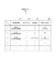
- FIG. 3 is a diagram schematically illustrating a configuration example of the connection partner list 180 held in the memory 150 according to the first embodiment of the present technology.
- the connection partner list 180 includes terminal identification information 181, MAC (Media Access Control Address) address 182, terminal type 183, and specific application correspondence 184. These pieces of information are acquired from each wireless communication device by executing Device Discovery or the like, and are sequentially recorded by the control unit 140.
- MAC Media Access Control Address
- the terminal identification information 181 is identification information (for example, a device unique ID) for identifying each wireless communication device.
- terminal identification information is represented by “AAAA”, “BBBB”, “CCCC”, and the name of the corresponding wireless communication device is represented in parentheses.
- the MAC address 182 is a physical address that is uniquely assigned to each wireless communication device.
- the terminal type 183 is information indicating the type of each wireless communication device.
- the specific application correspondence 184 is information indicating whether each wireless communication apparatus supports a specific application (specific application).
- a wireless communication apparatus corresponding to a specific application is represented by “present”, and the name of the corresponding specific application is illustrated in parentheses.
- a wireless communication device that does not support a specific application is represented as “none”.
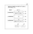
- FIG. 4 is a diagram illustrating a display screen example (connection content selection screen 190) displayed on the display unit 170 of the first wireless communication device 100 according to the first embodiment of the present technology.
- connection content selection screen 190 includes use application selection buttons 191 to 195, a cancel button 196, and an OK button 197.
- Use application selection buttons 191 to 195 are buttons for selecting a wireless communication device to be a connection partner and an application to be used by connection with the wireless communication device. Use application selection buttons 191 to 195 are displayed based on, for example, the contents of the connection partner list 180 shown in FIG. 3 (for example, terminal identification information 181 and specific application correspondence 184).
- the control unit 140 performs control for executing an application corresponding to the pressed button.
- the cancel button 196 is pressed.
- FIG. 5 and FIG. 6 an example (FIG. 5 and FIG. 6) of wireless packet transmission / reception until establishing a P2P (Peer-to-Peer) connection and operating a specific application is shown.
- P2P Peer-to-Peer
- FIG. 8 an example (FIG. 8) of wireless packet transmission / reception from the time when a specific application to be used is specified until the P2P connection is established and the specific application is operated before connection at the second layer is shown.
- FIG. 9 an example (FIG. 9) of wireless packet transmission / reception when a specific application is started after connection in the second layer is shown. Show.
- FIG. 5 and FIG. 6 are sequence charts showing examples of communication processing performed by each device serving as the basis of the present technology. Specifically, an example of a procedure for establishing a direct connection up to a connection according to the Wi-Fi Direct (Direct) standard (sometimes referred to as Wi-Fi P2P) standardized in the Wi-Fi Alliance is shown.
- Direction Wi-Fi Direct
- Wi-Fi P2P Wi-Fi P2P
- Wi-Fi Direct a plurality of wireless communication devices detect each other's presence (Device Discovery, Service Discovery). When a connected device is selected, direct connection is established between the selected devices by performing device authentication using WPS (Wi-Fi Protected Setup).
- WPS Wi-Fi Protected Setup
- a communication group is formed by determining whether a plurality of wireless communication devices play a role as a parent device (Group Owner) or a child device (Client).
- 5 and 6 show examples of communication processing between the first wireless communication device 100 and the second wireless communication device 200, but the same applies to communication processing between other wireless communication devices.
- Device Discovery is performed between the first wireless communication device 100 and the second wireless communication device 200 (501).
- the first wireless communication device 100 transmits a Probe request (response request signal) and receives a Probe response (response signal) for the Probe request from the second wireless communication device 200.
- wireless communication apparatus 200 can discover each other's presence.
- the device name and type (TV, PC, smartphone, etc.) of the other party can be acquired by Device Discovery.
- Service Discovery is performed between the first wireless communication device 100 and the second wireless communication device 200 (502).
- the first wireless communication device 100 transmits a Service Discovery Query that inquires about a service that is supported by the second wireless communication device 200 discovered by Device Discovery.
- the first wireless communication device 100 receives a Service Discovery Response from the second wireless communication device 200, thereby acquiring a service supported by the second wireless communication device 200.
- a service or the like that can be executed by the other party can be acquired by using Service Discovery.
- Services that can be executed by the other party are, for example, service and protocol (DLNA (Digital Living Network Alliance), DMR (Digital Media Renderer), etc.).
- DLNA Digital Living Network Alliance
- DMR Digital Media Renderer
- connection partner selection operation (connection partner selection operation) is performed by the user (503).
- This connection partner selection operation may occur only in one of the first wireless communication device 100 and the second wireless communication device 200.
- a connection partner selection screen is displayed on the display unit 170 of the first wireless communication device 100, and the second wireless communication device 200 is selected as a connection partner on the connection partner selection screen by a user operation.
- Group Owner Negotiation is performed between the first wireless communication device 100 and the second wireless communication device 200 (504).
- 5 and 6 show an example in which the first wireless communication device 100 becomes the group owner (Group (Owner) 505 and the second wireless communication device 200 becomes the client (Client) 506 based on the result of Group Owner Negotiation.
- the direct connection is established by performing each processing (507 to 510) between the first wireless communication apparatus 100 and the second wireless communication apparatus 200. That is, Association (L2 (second layer) link establishment) (507) and Secure link establishment (508) are sequentially performed. Moreover, L4 setup (510) on L3 by IP Address Assignment (509), SSDP (Simple Service Discovery) Protocol, etc. is sequentially performed.
- L2 (layer 2) means the second layer (data link layer)
- L3 (layer 3) means the third layer (network layer)
- L4 (layer 4) means the fourth layer (transport layer). ).
- a specific application is designated or activated by the user (application designation / activation operation) (511).
- This application designation / activation operation may occur only in one of the first wireless communication device 100 and the second wireless communication device 200.
- an application designation / startup operation screen (for example, a connection content selection screen 190 shown in FIG. 4) is displayed on the display unit 170 of the first wireless communication apparatus 100, and a specific application is operated by a user operation on the application designation / startup operation screen. Is selected.
- Wi-Fi Direct can acquire connection partner information when searching for a connection candidate partner in Device discovery or Service Discovery (option).
- the information of the connection partner is, for example, a basic device type, a corresponding specific application, or the like. And based on the acquired information of a connection other party, a user can be made to select a connection other party.
- This mechanism can be expanded to realize a wireless communication system in which a specific application is specified before connection at the second layer, a connection partner is selected, and the specific application is automatically started after this selection. Is possible.
- An example of the sequence leading to the connection in such a case is shown in FIG.
- FIG. 7 shows a configuration example of a frame format (frame format) transmitted and received in this communication process.
- FIG. 7 is a diagram schematically illustrating a configuration example of a frame format transmitted and received in communication processing by each device that is the basis of the present technology. That is, FIG. 7 shows a configuration example of a MAC frame for establishing a connection in the second layer. Specifically, it is an example of the frame format of Association Request / Response (527) for realizing the sequence shown in FIG.
- Frame Control (601) to Sequence Control (606) is a MAC header.
- the MAC frame shown in FIG. 7 is basically an Association Request / Response frame format described in sections 7.2.3.4 and 7.2.3.5 of the IEEE 802.11-2007 specification. is there. However, the difference is that not only the Information Element (hereinafter abbreviated as IE) defined in the IEEE 802.11 specification, but also an IE that has been independently extended.
- IE Information Element
- 127 is set as a decimal number in the IE Type (Information Element ID (611)).
- the length field (612) and the OUI field (613) are followed by the vendor specific content (614) according to the IEEE 802.11-2007 specification section 7.3.2.26.
- IE type (615) As the content of the vendor specific content (614), a field (IE type (615)) indicating the type of the vendor specific IE is first provided. Then, after this, it is conceivable that a plurality of subelements (616) can be stored.
- the contents of the subelement (616) include the name (617) of a specific application to be used and the role of the device (618) when the specific application is operating.
- information such as a port number used for control of a specific application (information for L4 setup) (619) and information on Capability (Capability information) in the specific application may be included.
- the capability information is information for specifying, for example, the case where the specific application to be specified is DLNA, which is compatible with audio transmission / reproduction, video transmission / reproduction, and the like.
- FIG. 8 is a sequence chart illustrating an example of communication processing performed by each device serving as the basis of the present technology.
- FIG. 8 shows an example of communication processing in the case where a specific application is specified before connection in the second layer, a connection partner is selected, and the specific application is automatically activated after this selection. Note that the sequence chart shown in FIG. 8 is a modified example in which a part of FIG. 5 and FIG. 6 is modified, and thus a part of the description of the part common to FIG. 5 and FIG. 6 is omitted.
- Device Discovery is performed between the first wireless communication device 100 and the second wireless communication device 200 (521).
- the vendor specific IE (610) shown in FIG. 7 can be included.
- the device discovery stage it is possible to acquire capability information such as that the device corresponds to a specific application (specific application) and the role that the device can play when the specific application is operated. it can.
- the role that the device can play when the specific application is operated is, for example, server / client, master / slave, source / sink, or the like.
- Service Discovery is performed between the first wireless communication device 100 and the second wireless communication device 200 (522).
- each process (523, 524) shown in FIG. 8 corresponds to each process (503, 504) shown in FIG.
- each process (527 to 529) is performed between the first wireless communication apparatus 100 and the second wireless communication apparatus 200, thereby establishing a direct connection.
- the frame (MAC frame) shown in FIG. 7 is transmitted / received as Association Request / Response. For this reason, it is possible to designate a specific application to be used after connection in the second layer in the step (527) of packet exchange (Association Request / Response) for establishing a connection in the second layer. In that stage (527), it is possible to include information necessary for using the specific application.
- the application to be used can be automatically determined by the difference from the example shown in FIG. 5 and FIG. 6 at the packet exchange stage (527) for establishing the connection in the second layer.
- One step can be saved.
- the stage of L4 setup (510) on L3 by SSDP or the like can be omitted. For this reason, as a user experience, the time taken to start the application can be shortened.
- FIG. 9 is a sequence chart illustrating an example of communication processing performed by each device serving as the basis of the present technology.
- FIG. 9 shows an example of communication processing when a specific application is activated using the mechanism shown in FIG. 8 after connection in the second layer.
- FIG. 9 the sequence chart shown in FIG. 9 is an example in which FIGS. 5, 6, and 8 are combined, and therefore a part of the description of the parts common to FIGS. 5, 6, and 8 is omitted.
- each process (501 to 512) shown in FIGS. 5 and 6 is performed.
- the processing surrounded by the rectangle 543 is to perform each processing (521 to 531) shown in FIG.
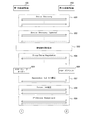
- FIG. 10 is a diagram schematically illustrating a configuration example of a frame format that is transmitted and received in the communication processing between the devices according to the first embodiment of the present technology. That is, FIG. 10 shows a configuration example of an action frame that triggers activation of a specific application (specific application activation) after connection in the second layer. Specifically, a structure example of a vendor specific action frame at the MAC layer level is shown.
- the vendor specific action frame is the action frame including the vendor specific IE.
- this action frame is a vendor specific one.
- the OUI field (640) and the Vendor Specific Content field (641) follow in accordance with section 7.4.5 of the IEEE 802.11-2007 specification.
- each information is, for example, the name of a specific application to be used and the role of the device when the specific application is operating.
- Each information is, for example, information such as a specific application or a port number used for control of the specific application (information for L4 setup), and capability information within the specific application.
- FIGS. 11 and 12 Various methods can be considered as a method of mounting the Vendor Specific Content field (641).
- the following two types of configuration examples shown in FIGS. 11 and 12 are shown. .
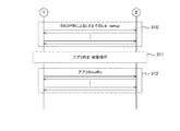
- FIG. 11 is a diagram schematically illustrating a configuration example of a frame format that is transmitted and received in the communication processing between the devices according to the first embodiment of the present technology. That is, an example is shown in which a vendor specific information element is used as the vendor specific content constituting the vendor specific action frame shown in FIG. That is, FIG. 11 shows a configuration method in the case of using an information element (IE).
- IE information element
- the vendor specific action frame in order to indicate what the vendor specific action frame is used for, it is preferable to divide it into a plurality of parts. For example, it is preferable to divide into a vendor specific content type (652) portion and a subsequent information element storage portion (653).
- the vendor specific content type (652) can indicate what the vendor specific action frame is used for.
- the action frame (vendor specific action frame) is provided with the type information part (652) and the information element part (653).
- the type of each frame is described in the vendor specific content type (652).
- This type is, for example, a type indicating a request frame for indicating activation of a specific application to a connection partner while a P2P L2 (second layer) link exists, and a type indicating a response frame for responding to the type.
- a Length field (655) and an OUI field (656) follow as shown in section 7.3.2.26 of the IEEE 802.11-2007 specification. After this, a vendor specific content (657) is arranged.
- the vendor specific content (657) is divided into an information element type (658) and a subelement (659) that is a constituent element of the information element type (658).
- the subelements portion (659) is divided into a plurality of subelements (660 to 663).
- the type part (658) includes information indicating that it is an information element for starting a specific application, and the subelements part (659) includes each piece of information.
- each information included in the subelements part (659) is a name of a specific application (660) to be used and a role of the device (661) when the specific application is operated.
- Each information includes a specific application or information such as a port number used for controlling a specific application (information for L4 setup) (662), and Capability information in a specific application (663). It is.
- the capability information is, for example, information corresponding to audio transmission / reproduction, video transmission / reproduction, and the like when the specific application to be specified is DLNA.
- Each information included in the subelements part (659) will be described in detail with reference to FIG.
- the information element type itself may be classified to specify a specific application to be started.
- a subelement that designates the type of a specific application that triggers activation is not necessary as the subelement.
- the transmission side (for example, the first wireless communication device 100) transmits an action frame for requesting activation of a specific application including such an information element to the reception side (for example, the second wireless communication device 200). Further, when receiving the action frame, the receiving side returns an action frame of a response including a corresponding information element (response to the action frame that requests activation of a specific application).
- the intentions of both the transmission side and the reception side can be matched, and a specific application can be automatically started on both sides. Accordingly, the operation of a specific application can be started based on the control information in the L2 (second layer) link.
- the predetermined portion to be encapsulated and sent is an association request frame or a frame body portion of an association response frame including a specific information element.
- a configuration example of the frame format of this mounting method is shown in FIG.
- FIG. 12 is a diagram schematically illustrating a configuration example of a frame format that is transmitted and received in the communication processing between the devices according to the first embodiment of the present technology. That is, an example is shown in which association is used as the Vendor Specific Content constituting the vendor specific action frame shown in FIG.
- the vendor specific action frame in order to indicate what the vendor specific action frame is used for, it is preferable to divide it into a plurality of parts. For example, it is preferable to divide into a vendor specific content type (672) portion and an information element storage portion (673) for encapsulating the subsequent frames.
- the vendor specific content type (672) can indicate what the vendor specific action frame is used for.
- each frame is described in the vendor specific content type (672).
- This type is, for example, a type indicating an action frame that encapsulates an association request frame for indicating a specific application activation to a connection partner while a P2P L2 (second layer) link exists.
- P2P L2 second layer
- it is a type indicating an action frame that encapsulates an association response frame for responding to it.
- the association request frame or the body part (675) of the association response frame when responding to the information is stored.
- the format itself of the body part (675) of the encapsulation request frame or the association response frame to be encapsulated has the same configuration as the frame body shown in FIG. Further, the format of the body part (675) itself is equivalent to that shown in FIG. 11, and the information elements for starting the specific application included in the body part (675) are also shown in FIG. It is equivalent. For this reason, the detailed description about these is abbreviate
- an association request frame to which an information element for starting a specific application is added is encapsulated in an action frame and transmitted to the connection partner. Accordingly, it is possible to notify the connection partner that the specific application is requested to be started while maintaining the existing L2 (second layer) link.
- the connection partner that has received it can encapsulate an association response frame to which an information element for activating a specific application is added, into an action frame and send it back.
- the intentions of both the transmission side and the reception side can be matched, and a specific application can be automatically activated on both sides. Thereby, the operation of a specific application can be started based on the control information in the existing L2 (second layer) link.
- FIG. 13 is a diagram illustrating an example of information elements that are transmitted and received in the communication process between each communication according to the first embodiment of the present technology.
- This information element is a subelements part (659) shown in FIG. 11 and a subelements part (681) shown in FIG.
- Wi-Fi CERTIFIED Miracast and an application (for example, DLNA) using P2P are shown as examples of applications, and each of these information elements is classified for each application type 686.
- Wi-Fi CERTIFIED Miracast uses Wi-Fi Direct and TDLS technologies to transmit audio and display video that is played on one terminal to another terminal, and the other terminal can transmit the audio, This is a mirroring technology that outputs video data.
- An example of displaying an image by Wi-Fi CERTIFIED Miracast will be described in detail with reference to FIG.
- the name of the corresponding application (specific application) is stored in Application to be triggered (687).
- the application type 686 is Wi-Fi CERTIFIED Miracast.
- information to be stored in Application to be triggered (687) can be specified by IE Type (658) shown in FIG.
- the IE Type (658) shown in FIG. 11 can specify a level such as “application that uses P2P”. Therefore, when the application type 686 is an application using P2P, the name of the corresponding application (specific application) is stored in Application to be triggered (687).
- information regarding the role of the first wireless communication device 100 is stored.
- the application type 686 is Wi-Fi CERTIFIED Miracast
- information indicating whether the role of the first wireless communication apparatus 100 is Source or Sink is stored. That is, information on the source or sink that conforms to the Wi-Fi Display specification is stored as information on the role of the first wireless communication apparatus 100.
- Source and Sink will be described in detail with reference to FIG.
- the application type 686 is an application using P2P. In this case, information indicating whether the role of the first wireless communication apparatus 100 is DMC (Digital Media Controller) or DMR (Digital Media Renderer) is stored.
- DMC Digital Media Controller
- DMR Digital Media Renderer
- information related to the fourth layer is stored in the L4 setup information (689).
- the application type 686 when the application type 686 is Wi-Fi CERTIFIED Miracast, information about RTSP described in the Wi-Fi Display specification is stored.
- the application type 686 when the application type 686 is Wi-Fi CERTIFIED Miracast, information on the port number used for RTSP is stored.
- at least one of information related to RTSP and information related to the port number may be stored.
- the application type 686 is an application that uses P2P
- information related to a control protocol corresponding to the application is stored.
- the application type 686 when the application type 686 is an application using P2P, information regarding a port number used for a control protocol corresponding to the application is stored. Note that at least one of information on the control protocol and information on the port number may be stored.
- capability information is stored.
- content protection correspondence information is stored.
- This content protection correspondence information is, for example, information on whether or not content protection is compliant with the Wi-Fi Display specification.
- the application type 686 is an application using P2P, information on the presence / absence of video data correspondence and audio data correspondence is stored.
- WFD Wi-Fi Display
- FIG. 14 is a diagram illustrating an example of a WFD session (session) by the wireless communication device according to the first embodiment of the present technology.
- FIG. 14a shows an example of a WFD session when audio-only communication is performed.
- FIG. 14 b shows an example of a WFD session when only video communication is performed.
- FIG. 14 c shows an example of a WFD session when audio and video communication is performed.
- FIG. 14d shows an example of a WFD session in the case where communication is performed with linked sinks.
- the wireless communication device that plays the role of the transmitter is referred to as WFD Source.
- WFD Sources 701 to 704 shown in FIGS. 14A to 14D correspond to the WFD Source.
- WFD Sink a wireless communication device that plays the role of the receiver in the WFD session.
- the right side wireless communication devices (Secondary Sink or Primary Sink 705, Primary Sink 706 to 708, Secondary Sink 709) shown in FIGS. 14A to 14D correspond to WFD Sink.
- WFD Sources 701 to 704 transmit content data (video (video) data and audio (audio) data) to WFD Sink.
- the Primary Sink is a WFD Sink corresponding to only a video content, only an audio content, or video + audio contents.
- the Secondary Sink is a WFD Sink that corresponds only to the audio content.
- Information regarding the role of these wireless communication devices (information indicating whether the role of the wireless communication device is the source or the sink) is stored in the Device Role in this application (688) shown in FIG.
- FIG. 15 is a diagram illustrating a display example when wireless communication of image data is performed by the Wi-Fi CERTIFIED Miracast in the communication system 10 according to the first embodiment of the present technology.
- FIG. 15 illustrates an example in which image data is wirelessly communicated between the first information processing apparatus 100 and the second information processing apparatus 200 and the same moving image is displayed on both display units.
- the first information processing apparatus 100 transmits image data for displaying the same moving image as the moving image displayed on the display unit 170 to the second information processing apparatus 200.
- a moving image of a horse running on the seaside is displayed on the display unit 170 of the first information processing apparatus 100.
- the control unit 140 of the first information processing apparatus 100 displays image data for displaying the same moving image as the moving image (horse running on the seaside) displayed on the display unit 170 as the second information processing device 200. Control to make it transmit.
- audio data can be associated with the image data and transmitted.
- control unit of the second information processing device 200 causes the display unit 201 to display a moving image (horse running on the seaside) based on the image data transmitted from the first information processing device 100. Further, when audio data is associated with the image data, the control unit of the second information processing device 200 outputs audio based on the audio data transmitted from the first information processing device 100 to an audio output unit (not shown). ).
- the first information processing apparatus 100 includes an imaging unit for generating a moving image.
- the first information processing apparatus 100 displays the moving image generated by the imaging unit on the display unit 170 and also displays image data for displaying the same moving image as the moving image. Can be displayed on the display unit 201.
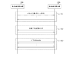
- FIG. 16 is a sequence chart illustrating an example of communication processing by each device according to the first embodiment of the present technology.
- FIG. 16 shows an example of communication processing when a specific application is started after connection in the second layer.
- each process (501 to 512) shown in FIGS. 5 and 6 is performed.
- the specific application activation is realized by packet exchange for the specific application activation (552).
- each frame (action frame) shown in FIGS. 10 to 12 is transmitted and received.
- the actual data transmission of the specific application can be performed (553).
- each process such as L2 (second layer) link temporary disconnection (542) can be omitted.
- Each process that can be omitted is, for example, the second device discovery and the second service discovery (optional).
- each process that can be omitted is, for example, the second Group Owner negotiation, the second Association, the second secure link establishment, and the second IP address assignment.
- the next specific application can be started in a short time.
- connection partner is compatible with the vendor specific action frame exchange.
- information indicating that the received frame cannot be recognized can be transmitted to notify that the connection partner is not compatible with the vendor specific action frame.
- 128 to 255 is specified in the category field in the action frame, and the response including the received information element is directly used. Send back. Thereby, it can be notified that the receiving side is not compatible with the vendor specific action frame.
- vendor specific action frame itself can be interpreted, it is assumed that the specified specific application is not supported. In this case, non-correspondence can be notified by sending a reply using an error code defined as a vendor specific information element.
- the action frame is used in the range of the IEEE 802.11-2007 specification.
- GAS generator advertisement service
- the frame is not encrypted. For this reason, it is preferable to use the action frame when exchanging information between wireless communication apparatuses in which L2 (second layer) link is already established and secure link is established.
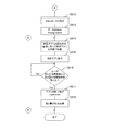
- FIGS. 17 to 19 are flowcharts illustrating an example of a processing procedure of communication processing by the first wireless communication device 100 according to the first embodiment of the present technology.
- Steps S901 to S905 correspond to 521 and 522 shown in FIG.
- Steps S906 to S909 correspond to 523 shown in FIG.
- Step S910 corresponds to 524 shown in FIG.
- Steps S911 to S915 correspond to 527 to 531 shown in FIG.
- Step S919 corresponds to 504 shown in FIG.
- Steps S920 to S926 correspond to 507 to 512 shown in FIGS.
- Steps S927 to S933 and S914 correspond to 552 shown in FIG.
- step S915 corresponds to 553 shown in FIG.
- the control unit 140 executes Device Discovery (step S901). Subsequently, the control unit 140 determines whether or not IE (corresponding to 610 shown in FIG. 7) indicating the correspondence with the specific application is included in the information from the partner device discovered by Device Discovery (step S902). The information from this partner device is Device Discovery request or Device Discovery response.
- the control unit 140 lists the discovered device as the specific application compatible partner (for example, the connection partner list 180 illustrated in FIG. 3). Recording is performed (step S903). If the IE indicating the specific application correspondence is not included (step S902), the control unit 140 lists the discovered devices as non-specific application counterparts (for example, the connection partner list 180 illustrated in FIG. 3).
- Step S904 For example, when the IE indicating the specific application correspondence is included, “Yes” is recorded in the specific application correspondence 184 of the connection partner list 180 illustrated in FIG. 3, and the IE indicating the specific application correspondence is not included. “None” is recorded in the specific application correspondence 184.
- control unit 140 determines whether all partner devices discovered by Device Discovery have been recorded in the list (step S905). If all of the partner devices have not been recorded in the list, the control unit 140 proceeds to step S902. Return. When all of them are recorded in the list (step S905), the control unit 140 determines whether or not a connection partner designation operation has been performed by the user (step S906).
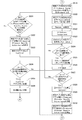
- step S906 the control unit 140 determines whether a connection request is received from the partner device (step S907). If a connection request has not been received from the counterpart device (step S907), the process waits (step S908) and returns to step S901. If a connection request is received from the counterpart device (step S907), the process proceeds to step S909.
- step S906 When a connection partner designation operation is performed by the user (step S906) or when a connection request is received from the partner device (step S907), the control unit 140 determines whether or not a specific application has been designated thereby. Is determined (step S909). For example, on the connection content selection screen 190 shown in FIG. 4, the user performs a connection partner designation operation and a specific application designation operation. Further, based on information included in the connection request received from the counterpart device, it is determined whether or not a specific application has been designated.
- step S909 the control unit 140 adds the IE corresponding to the specific application and executes Group Owner Negotiation (step S910).
- the first wireless communication device 100 becomes a GO (Group Owner) or a client.
- control unit 140 adds the IE corresponding to the specific application, executes association, and connects in the second layer (step S911). Subsequently, the control unit 140 causes the secure link to be established (step S912) and causes the IP address assignment to be executed (step S913).
- control unit 140 automatically activates the specific application according to the information in the specific application-corresponding IE (step S914), and operates the specific application (step S915). Subsequently, the control unit 140 determines whether or not the second layer disconnection request has been received from the user or the connection partner (step S916). If the second layer disconnection request has not been received, the control unit 140 continues monitoring. Do it. On the other hand, when a request for cutting the second layer is received (step S916), the control unit 140 executes a termination process for a specific application (step S917) and executes a cutting process for the second layer (step S918). ), The operation of the communication process is terminated.
- control unit 140 executes Group Owner Negotiation without adding the specific application-compatible IE (step S919).
- Group Owner negotiation the first wireless communication device 100 becomes a GO (Group Owner) or a client.
- control unit 140 executes association without adding the IE for the specific application and connects in the second layer (step S920). Subsequently, the control unit 140 causes the secure link to be established (step S921), and causes the IP address assignment to be executed (step S922).
- control unit 140 confirms the corresponding application by SSDP and executes L4 setup (step S923). Subsequently, the control unit 140 determines whether or not an application activation instruction has been received from the user or the connection partner (step S924). If no application activation instruction has been received, monitoring is continued. On the other hand, when the application activation instruction is received (step S924), the control unit 140 activates the application according to the application activation instruction (step S925) and operates the application (step S926).
- control unit 140 determines whether or not an instruction to start a specific application has been received from the user (step S927).
- the control unit 140 selects an active application. Stop (step S928).
- the control unit 140 transmits the vendor specific action frame of the application activation trigger request including the specific application-corresponding IE to the connection partner (step S929).
- the control unit 140 receives the vendor specific action frame of the application activation trigger response including the IE for the specific application from the connection partner (step S930).
- a user operation for starting wireless communication of image data is accepted as an instruction to start the specific application (step S927).
- a user operation for example, a touch operation on the touch panel, a pressing operation by the operation member
- the control unit 140 transmits a Vendor Specific Action frame to the connection partner based on the reception timing of the user operation (user operation for starting wireless communication of image data) (step S929).
- the Vendor Specific Action frame is, for example, the Action frame shown in FIGS. 10 to 12 and includes the Vendor Specific IE (IE for specific applications).
- control unit 140 automatically activates the specific application according to the information in the specific application-corresponding IE (step S914), and operates the specific application (step S915).
- step S927 the control unit 140 determines whether or not the Vendor Specific Action frame of the application activation trigger request including the specific application corresponding IE has been received (step S931). .
- step S931 the control unit 140 transmits the vendor specific action frame of the application activation trigger response including the specific application-compatible IE to the connection partner (step S932). Subsequently, the control unit 140 stops the running application (step S933), and proceeds to step S914.
- a user operation for starting wireless communication of image data is accepted at the connection partner as an instruction to start the specific application.
- a user operation for starting wireless communication of image data shown in FIG. 15 is accepted by the connection partner.
- the communication unit 102 receives a Vendor Specific Action frame from the connection partner based on the reception timing of the user operation (user operation for starting wireless communication of image data) (step S931).
- step S931 the control unit 140 determines whether a second layer disconnection request has been received from the user or the connection partner (step S934). If the second layer cutting request has not been received (step S934), the process returns to step S927 to continue monitoring. On the other hand, when the second layer cutting request is received (step S934), the control unit 140 executes an application termination process (step S935), and executes a second layer cutting process (step S936). The communication processing operation is terminated.
- stop processing (steps S928 and S933) for stopping the running application will be described.
- the running application (first application) is DLNA and the application that is instructed to start during the operation of the first application (second application) is Wi-Fi CERTIFIED Miracast.
- the second application is an example of a specific application that is activated by transmitting / receiving an action frame request / response.
- one of the wireless communication devices when stopping an active application, one of the wireless communication devices (the first wireless communication device 100 or the connection partner) transmits a FIN packet (finish packet) to the other wireless communication device.
- a FIN packet can be transmitted over TCP (TransmissionTransControl Protocol) used for HTTP (HyperText Transfer Protocol) of DLNA.
- TCP TransmissionTransControl Protocol
- HTTP HyperText Transfer Protocol
- a wireless communication apparatus that has transmitted a request frame transmits a FIN packet.
- the wireless communication apparatus that has received the FIN packet returns an ACK packet (ACKnowledgement packet) to the connection partner (the wireless communication apparatus that has transmitted the FIN packet).
- the wireless communication apparatus that has transmitted the ACK packet transmits a FIN packet to the connection partner (the wireless communication apparatus that is the transmission destination of the ACK packet). Also, the wireless communication device that has received the FIN packet (the wireless communication device that first transmitted the FIN packet) transmits an ACK packet to the connection partner (the wireless communication device that transmitted the next FIN packet in response to the first FIN packet). Reply.
- the TCP port close processing used in DLNA is performed, and resources are released.
- RTSP for Wi-Fi CERTIFIED Miracast is started in parallel with DLNA data transmission not being completed (FIN packet and ACK packet are being exchanged).
- the data received by the connection partner is simply discarded without passing to the application. Therefore, RTSP for Wi-Fi CERTIFIED Miracast may be started in parallel before the exchange of the FIN packet and the ACK packet for two times is completed between the wireless communication apparatuses.
- RTSP for Wi-Fi CERTIFIED Miracast may be started after the exchange of the FIN packet and the ACK packet for two times is completed between the wireless communication apparatuses.
- a timeout may occur at the start of RTSP. For this reason, it is preferable to set an appropriate timing for the RTSP start timing for Wi-Fi CERTIFIED Miracast.
- the TCP port of UPnP may be utilized as it is or may be closed once.
- UPnP is used from the discovery of DLNA devices to the capability confirmation.
- the example in which the operation of the first application is terminated based on the timing at which the operation of the second application starts is shown.
- the first application in operation may be terminated after the second application is established and the exchange of content data is started.
- the operation of the first application may be started without ending, and the data transmission / reception amount (communication amount) related to the first application may be suppressed.
- the transmission / reception amount of data related to the first application can be suppressed based on the timing when the operation of the second application starts.
- a connection is maintained between the wireless communication apparatuses so as not to be disconnected from the connection partner. For example, without transmitting and receiving video data and audio data, it is possible to exchange only information for keep alive so that the first application does not cause a timeout.
- the operation status of the first application (for example, the status of information exchange for keep-alive) is confirmed regularly or irregularly. Note that, as a result of this confirmation, if there is no response from the connection partner, the first application may be terminated.
- the case where the first application is DLNA and the second application is Wi-Fi CERTIFIED Miracast has been described as an example.
- the same can be applied to the case where the first application is another application (for example, an application for transferring a file, copying a file, or the like).
- steps S901 to S926 are an example of the first procedure described in the claims.
- Steps S929 and S932 are an example of the second procedure described in the claims.
- the communication unit 102 performs each reception process and each transmission process based on the control of the control unit 140. For example, the communication unit 102 performs inter-device wireless communication with other wireless communication devices in accordance with the Wi-Fi Direct specification. Further, the communication unit 102 transmits information regarding the role of the first wireless communication device 100, information regarding the fourth layer, and capability information included in an action frame defined in the IEEE 802.11 specification. In this case, the communication unit 102 performs transmission when P2P connection is established with another wireless communication device.
- the communication unit 102 receives an action frame defined in the IEEE802.11 specification including information on the role of the first wireless communication apparatus 100, information on the fourth layer, and capability information. In this case, the communication unit 102 performs reception when P2P connection is established with another wireless communication device.
- control unit 140 operates the first application designated in the connection discovery process based on the timing at which the connection for inter-device wireless communication is established. Further, when the communication unit 102 executes the second application while the first application is operating, the communication unit 102 includes information related to the second application in an action frame defined in the IEEE 802.11 specification. To do.
- the information regarding the second application is, for example, at least one of information regarding the role of the first wireless communication apparatus 100, information regarding the fourth layer, and capability information.
- the control unit 140 can end the first application based on the timing when the operation of the second application starts. Moreover, the control part 140 can suppress the communication amount of the data regarding a 1st application based on the timing which the operation
- the communication unit 102 executes the second application while the first application is operating, the communication unit 102 receives an action frame defined in the IEEE 802.11 specification including information related to the second application. .
- the protocol switching unit 141 switches between a protocol corresponding to the first application and a protocol corresponding to the second application as a protocol using the inter-device wireless communication.
- the protocol switched by the protocol switching unit 141 is a protocol corresponding to the second application (for example, Wi-Fi CERTIFIED Miracast).
- the communication unit 102 transmits the image data displayed on the display unit 170 to another wireless communication device using the protocol switched by the protocol switching unit 141. Further, the communication unit 102 receives image data displayed on the display unit 140 from another wireless communication device using the protocol switched by the protocol switching unit 141.
- control unit 140 perform control to specify the application.
- the control unit 140 includes information (shown in FIGS. 10 to 12) corresponding to an information element (shown in FIG. 7) for designating a specific application without disconnecting the wireless connection.
- Control to specify a specific application by sending and receiving data.
- the control unit 140 transmits and receives an encrypted frame as data including information corresponding to the information element.
- the control unit 140 corresponds to an information element for designating activation of a specific application without disconnecting the wireless connection when a specific application is designated by a user operation after establishing the wireless connection. Send the data including the information to be used.
- the specific application is specified by this transmission.
- data including information corresponding to an information element for designating activation of a specific application is received from a wireless communication device (for example, the second wireless communication device 200) connected wirelessly.
- the control unit 140 transmits data including information corresponding to an information element for designating activation of the specific application as a response to the data without disconnecting the wireless connection. For example, it transmits to the 2nd radio
- the specific application is specified by this transmission.
- the control unit 140 transmits / receives a vendor specific action frame defined in the IEEE 802.11 specification as data including information corresponding to the information element.
- the control unit 140 transmits a request frame that uses a vendor specific information element as its information element as a vendor specific action frame.
- the control unit 140 transmits a response frame using a vendor specific information element as the information element as the vendor specific action frame.
- control unit 140 encapsulates the association request frame body including the information element into the vendor specific action frame and transmits the encapsulated request frame.
- this association request frame body a vendor specific information element is used as an information element, and the information element is included in the association request frame body.
- control unit 140 encapsulates an association response frame body including the information element into a vendor specific action frame and transmits the encapsulated response frame.
- association response frame body a vendor specific information element is used as an information element and includes the information element.
- control unit 140 When a specific application that has not been specified in the establishment process is newly specified after establishing the wireless connection, the control unit 140 performs control for specifying the new specific application. May be. Moreover, the communication part 102 and the control part 140 are examples of the transmission part as described in a claim.
- a specific application can be specified during device discovery or service discovery performed before establishing a connection in the second layer. Even when a specific application is not specified during device discovery or service discovery, a frame including a predetermined information element can be sent after establishing a connection in the second layer.
- the predetermined information element is, for example, an information element transmitted / received at the time of device discovery or service discovery.
- Wi-Fi CERTIFIED Miracast can be started without disconnecting the connection in the second layer. That is, even when switching to a specific application (for example, Wi-Fi CERTIFIED Miracast) after connection in the second layer, disconnection and reconnection in the second layer can be omitted. Thereby, a user's effort and a user's waiting time can be reduced. In addition, the number of packets necessary for the operation can be reduced, and congestion of the wireless communication path can be reduced.
- information necessary for starting a specific application is exchanged using an action frame used one-on-one. Since this action frame can be encrypted, it is possible to increase resistance to attacks from others from the viewpoint of security.
- Second Embodiment> In the first embodiment of the present technology, an example of a wireless communication device that exchanges various types of information using wireless communication has been described.
- the first embodiment of the present technology can also be applied to an information processing device (for example, a semiconductor integrated circuit) used in a wireless communication device.
- an information processing device for example, a semiconductor integrated circuit
- an example of an information processing device for example, a semiconductor integrated circuit used for a wireless communication device is shown.
- FIG. 20 is a block diagram illustrating a configuration example of the information processing device 800 according to the second embodiment of the present technology.
- the information processing apparatus 800 includes a processor 810 and a memory 820.
- the information processing apparatus 800 is realized by a semiconductor integrated circuit.
- FIG. 20 illustration and description of components other than the processor 810 and the memory 820 are omitted.
- the processor 810 is a processor that executes each process based on a program stored in the memory 820.
- the memory 820 is a memory that stores a program for causing the processor 810 to execute each process.
- the program stored in the memory 820 is a program for causing the processor 810 to execute each process described in the first embodiment of the present technology.
- a wireless communication apparatus using the information processing apparatus 800 operates as a transmission side.
- the program stored in the memory 820 causes the processor 810 to execute a first procedure for performing inter-device wireless communication with other devices in accordance with the Wi-Fi Direct specification. Further, the program stored in the memory 820 executes the second procedure for transmitting to the processor 810 the information regarding the role of the wireless communication device used by the information processing device 800 included in the action frame defined in the IEEE 802.11 specification.
- the program stored in the memory 820 causes the processor 810 to execute a first procedure for performing inter-device wireless communication with other devices in accordance with the Wi-Fi Direct specification.
- the program stored in the memory 820 executes, in the processor 810, the second procedure for receiving an action frame defined in the IEEE 802.11 specification including information regarding the role of the wireless communication device in which the information processing device 800 is used.
- a program stored in the memory 820 causes the processor 810 to execute a procedure for performing signal processing for processing image data. Further, for example, the program stored in the memory 820 causes the processor 810 to execute a procedure for adjusting the power consumption according to the operation of the processor 810.
- FIG. 21 is a diagram illustrating a relationship example between the performance and the power consumption of the information processing apparatus 800 according to the second embodiment of the present technology.
- the vertical axis indicates the power consumption (power) of the information processing apparatus 800
- the horizontal axis indicates the performance (performance) of the information processing apparatus 800.
- the information processing apparatus 800 is controlled so that the power consumption does not exceed the thermal limit value even when the performance is improved. That is, the processor 810 performs control so as to adjust the power consumption according to the operation of the own device.
- Wi-Fi CERTIFIED Miracast can be started without disconnecting the connection in the second layer.
- the processing procedure described in the above embodiment may be regarded as a method having a series of these procedures, and a program for causing a computer to execute these series of procedures or a recording medium storing the program. You may catch it.
- a recording medium for example, a CD (Compact Disc), an MD (MiniDisc), a DVD (Digital Versatile Disc), a memory card, a Blu-ray Disc (Blu-ray Disc (registered trademark)), or the like can be used.
- a wireless communication device that performs inter-device wireless communication with another wireless communication device in accordance with Wi-Fi (Wireless Fidelity) Direct specifications
- a wireless communication apparatus comprising: a transmitter that transmits information relating to the role of the wireless communication apparatus in an action frame defined in IEEE (Institute of Electrical and Electronic Engineers) 802.11 specifications.
- the transmission unit performs the transmission when connected to the other wireless communication device by P2P (Peer to Peer).
- the information related to the role of the wireless communication device is information related to a source or a sink that conforms to a Wi-Fi Display specification.
- the wireless communication device according to any one of (1) to (3), wherein the action frame is a vendor specific action frame defined in the IEEE 802.11 specification. (5) The wireless communication device according to (4), wherein the information regarding the role of the wireless communication device is included in a vendor specific content area of the vendor specific action frame. (6) The wireless communication device according to any one of (1) to (5), wherein a type information portion and an information element portion are provided in the action frame. (7) The said control part is a radio
- the wireless communication apparatus includes at least information regarding a port number used for the RTSP.
- the information on the role of the wireless communication device and the information on the fourth layer are arranged in the order of the information on the role of the wireless communication device and the information on the fourth layer in the action frame. Any one of the radio
- the wireless communication device according to any one of (1) to (10), wherein the transmission unit transmits capability information included in the action frame.
- the capability information includes at least information regarding presence / absence of correspondence of content protection based on Wi-Fi Display specifications.
- a communication unit that performs inter-device wireless communication with other devices discovered by the connection discovery process; A control unit that operates the first application designated in the connection discovery process based on the timing at which the connection of the inter-device wireless communication is established, When the communication unit executes the second application while the first application is operating, the communication unit includes information related to the second application in an action frame defined in the IEEE 802.11 specification. Wireless communication device. (14) The wireless communication device according to (13), wherein the control unit terminates the first application based on a timing at which the operation of the second application starts.
- the said communication part is a radio
- the control unit confirms an operation state of the first application regularly or irregularly after the operation of the second application starts.
- DLNA Digital Living Network Alliance
- the wireless communication device wherein the communication unit transmits a FIN packet (finish packet) on a TCP (Transmission Control Protocol) based on a timing at which the operation of the second application starts.
- a wireless communication device that performs inter-device wireless communication with another wireless communication device in accordance with Wi-Fi (Wireless Fidelity) Direct specifications, A transmitter that transmits information on the role of the wireless communication device in an action frame defined in IEEE (Institute of Electrical and Electronic Engineers) 802.11 specifications; A display for displaying image data; A wireless communication apparatus comprising: a protocol switching unit that switches a protocol that uses the inter-device wireless communication.
- An operation receiving unit for receiving user operations The wireless transmission according to (20), wherein the transmission unit transmits information regarding the role of the wireless communication device based on a reception timing of a user operation for starting communication of image data received by the operation reception unit. Communication device.
- a processor A memory for storing a program to be executed by the processor;
- the program is A first procedure for performing inter-device wireless communication with other devices in accordance with the Wi-Fi Direct specification;
- An information processing apparatus that causes the processor to execute a second procedure in which information relating to a role of a wireless communication apparatus in which the information processing apparatus is used is included in an action frame defined in the IEEE 802.11 specification and transmitted.
Abstract
Description
1.第1の実施の形態(通信制御:第2層での接続を切断せずに、第2層での接続後に用いる特定のアプリケーションを指定する例)
2.第2の実施の形態(通信制御:無線通信装置に用いられる情報処理装置の例)
[通信システムの構成例]
図1は、本技術の第1の実施の形態における通信システム10の構成例を示す図である。
図2は、本技術の第1の実施の形態における第1無線通信装置100の機能構成例を示すブロック図である。なお、第2無線通信装置200、第3無線通信装置300および第4無線通信装置400の機能構成(無線通信に関する機能構成)については、第1無線通信装置100と略同様であるため、ここでの説明を省略する。また、以下では、第1無線通信装置100以外の各無線通信装置の各部を説明する際には、第1無線通信装置100と同一の符号を用いて説明する。
図3は、本技術の第1の実施の形態におけるメモリ150に保持される接続相手リスト180の構成例を模式的に示す図である。
図4は、本技術の第1の実施の形態における第1無線通信装置100の表示部170に表示される表示画面例(接続内容選択画面190)を示す図である。
ここで、本技術の基礎となる基本動作例について説明する。
図5および図6は、本技術の基礎となる各装置による通信処理例を示すシーケンスチャートである。具体的には、Wi-Fi Allianceにおいて標準化されているWi-Fiダイレクト(Direct)規格(Wi-Fi P2Pと呼ばれることもある)での接続に至るダイレクト接続の確立手順の一例を示す。
図7は、本技術の基礎となる各装置による通信処理において送受信されるフレームフォーマット(frame format)の構成例を模式的に示す図である。すなわち、図7には、第2層での接続を確立するためのMAC frameの構成例を示す。具体的には、図8に示すシーケンスを実現するためのAssociation Request/Response(527)のフレームフォーマットの一例である。
図8は、本技術の基礎となる各装置による通信処理例を示すシーケンスチャートである。図8には、第2層で接続する前に特定のアプリケーションを指定して接続相手を選択し、この選択後に、自動的に特定のアプリケーションを起動させる場合における通信処理例を示す。なお、図8に示すシーケンスチャートは、図5および図6の一部を変形した変形例であるため、図5および図6に共通する部分についての説明の一部を省略する。
図9は、本技術の基礎となる各装置による通信処理例を示すシーケンスチャートである。図9には、第2層での接続後に、図8に示す仕組みを用いて特定のアプリケーションを起動する場合における通信処理例を示す。
図10は、本技術の第1の実施の形態における各装置間の通信処理において送受信されるフレームフォーマット(frame format)の構成例を模式的に示す図である。すなわち、図10には、第2層での接続後に、特定のアプリケーションの起動(特定アプリ起動)をトリガするaction frameの構成例を示す。具体的には、MAC層レベルでのvendor specific action frameの構造例を示す。
図11は、本技術の第1の実施の形態における各装置間の通信処理において送受信されるフレームフォーマット(frame format)の構成例を模式的に示す図である。すなわち、図10に示すvendor specific action frameを構成するVendor Specific Contentとして、vendor specific Information Elementを用いる例を示す。すなわち、図11には、情報要素(IE)を用いる場合の構成方法を示す。
図12は、本技術の第1の実施の形態における各装置間の通信処理において送受信されるフレームフォーマット(frame format)の構成例を模式的に示す図である。すなわち、図10に示すvendor specific action frameを構成するVendor Specific Contentとして、associationを用いる例を示す。
図13は、本技術の第1の実施の形態における各通信間の通信処理において送受信される情報要素の一例を示す図である。この情報要素は、図11に示すsubelements部分(659)、図12に示すsubelements部分(681)である。
図15は、本技術の第1の実施の形態における通信システム10においてWi-Fi CERTIFIED Miracastによる画像データの無線通信が行われている場合における表示例を示す図である。図15では、第1情報処理装置100および第2情報処理装置200間において画像データの無線通信を行い、双方の表示部に同一の動画を表示させる例を示す。
図16は、本技術の第1の実施の形態における各装置による通信処理例を示すシーケンスチャートである。図16には、第2層での接続後に、特定のアプリケーションを起動する場合における通信処理例を示す。
図17乃至図19は、本技術の第1の実施の形態における第1無線通信装置100による通信処理の処理手順の一例を示すフローチャートである。
本技術の第1の実施の形態では、無線通信を利用して各種情報のやり取りを行う無線通信装置の例を示した。ここで、無線通信装置に用いられる情報処理装置(例えば、半導体集積回路)についても本技術の第1の実施の形態を適用することができる。
図20は、本技術の第2の実施の形態における情報処理装置800の構成例を示すブロック図である。
図21は、本技術の第2の実施の形態における情報処理装置800の性能と消費電力との関係例を示す図である。
(1)
Wi-Fi(Wireless Fidelity) Direct仕様に従って他の無線通信装置と機器間無線通信を行う無線通信装置であって、
前記無線通信装置の役割に関する情報をIEEE(Institute of Electrical and Electronic Engineers)802.11仕様に定められたaction frameに含めて送信する送信部を具備する無線通信装置。
(2)
前記送信部は、前記他の無線通信装置とP2P(Peer to Peer)接続されている場合に前記送信を行う前記(1)に記載の無線通信装置。
(3)
前記無線通信装置の役割に関する情報は、Wi-Fi Display仕様に準拠したsourceまたはsinkに関する情報である前記(1)または(2)に記載の無線通信装置。
(4)
前記action frameは、IEEE802.11仕様に定められたvendor specific action frameである前記(1)から(3)のいずれかに記載の無線通信装置。
(5)
前記無線通信装置の役割に関する情報は、前記vendor specific action frameのうちのvendor specific contentの領域に含められる前記(4)に記載の無線通信装置。
(6)
前記action frameには、タイプ情報部および情報要素部が設けられる前記(1)から(5)のいずれかに記載の無線通信装置。
(7)
前記制御部は、第4層に関する情報を前記action frameに含めて送信する前記(1)から(6)のいずれかに記載の無線通信装置。
(8)
前記第4層に関する情報は、RTSPに関する情報を少なくとも含む前記(7)に記載の無線通信装置。
(9)
前記第4層に関する情報は、前記RTSPに用いられるport番号に関する情報を少なくとも含む前記(8)に記載の無線通信装置。
(10)
前記無線通信装置の役割に関する情報および前記第4層に関する情報は、前記action frameにおいて前記無線通信装置の役割に関する情報、前記第4層に関する情報の順に配置される前記(7)から(9)のいずれかに記載の無線通信装置。
(11)
前記送信部は、capability情報を前記action frameに含めて送信する前記(1)から(10)のいずれかに記載の無線通信装置。
(12)
前記capability情報は、Wi-Fi Display仕様に準拠したcontent protectionの対応の有無に関する情報を少なくとも含む前記(11)に記載の無線通信装置。
(13)
接続発見処理により発見された他の機器と機器間無線通信を行う通信部と、
前記機器間無線通信の接続が確立されたタイミングに基づいて前記接続発見処理において指定された第1のアプリケーションを動作させる制御部とを具備し、
前記通信部は、前記第1のアプリケーションが動作している状態で第2のアプリケーションを実行する際に、前記第2のアプリケーションに関する情報を、IEEE802.11仕様に定められたaction frameに含めて送信する
無線通信装置。
(14)
前記制御部は、前記第2のアプリケーションの動作が開始するタイミングに基づいて前記第1のアプリケーションを終了させる前記(13)に記載の無線通信装置。
(15)
前記制御部は、前記第2のアプリケーションの動作が開始するタイミングに基づいて前記第1のアプリケーションに関するデータの通信量を抑制させる前記(13)に記載の無線通信装置。
(16)
前記制御部は、前記第2のアプリケーションの動作開始後に前記第1のアプリケーションの動作状況を定期的または不定期に確認する前記(15)に記載の無線通信装置。
(17)
前記第2のアプリケーションは、Wi-Fi CERTIFIED Miracastである前記(13)から(16)のいずれかに記載の無線通信装置。
(18)
前記第1のアプリケーションは、DLNA(Digital Living Network Alliance)である前記(13)から(17)のいずれかに記載の無線通信装置。
(19)
前記通信部は、前記第2のアプリケーションの動作が開始するタイミングに基づいて、TCP(Transmission Control Protocol)上でFINパケット(finish packet)を送信する前記(18)に記載の無線通信装置。
(20)
Wi-Fi(Wireless Fidelity) Direct仕様に従って他の無線通信装置と機器間無線通信を行う無線通信装置であって、
前記無線通信装置の役割に関する情報をIEEE(Institute of Electrical and Electronic Engineers)802.11仕様に定められたaction frameに含めて送信する送信部と、
画像データを表示する表示部と、
前記機器間無線通信を利用するプロトコルを切り換えるプロトコル切替部と
を具備する無線通信装置。
(21)
ユーザ操作を受け付ける操作受付部をさらに具備し、
前記送信部は、前記操作受付部によって受け付けられた、画像データの通信を開始するためのユーザ操作の受け付けタイミングに基づいて前記無線通信装置の役割に関する情報を送信する
前記(20)に記載の無線通信装置。
(22)
前記送信部は、前記プロトコル切替部によって切り換えられたプロトコルを用いて前記表示部に表示される画像データを送信する前記(20)または(21)に記載の無線通信装置。
(23)
プロセッサと、
前記プロセッサに実行させるプログラムを記憶するメモリとを具備し、
前記プログラムは、
Wi-Fi Direct仕様に従って他の機器と機器間無線通信を行う第1手順と、
当該情報処理装置が用いられる無線通信装置の役割に関する情報をIEEE802.11仕様に定められたaction frameに含めて送信する第2手順とを前記プロセッサに実行させる
情報処理装置。
(24)
前記プログラムは、画像データを処理するための信号処理を行う手順をさらに前記プロセッサに実行させる前記(23)に記載の情報処理装置。
(25)
前記プログラムは、前記プロセッサの動作に応じて消費電力を調整する手順をさらに前記プロセッサに実行させる前記(23)または(24)に記載の情報処理装置。
(26)
Wi-Fi Direct仕様に従って他の無線通信装置と機器間無線通信を行う第1手順と、
当該無線通信装置の役割に関する情報をIEEE802.11仕様に定められたaction frameに含めて送信する第2手順と
を具備する通信方法。
100 第1無線通信装置
101 アンテナ
110 データ処理部
120 伝送処理部
130 無線インターフェース部
140 制御部
141 プロトコル切替部
150 メモリ
160 操作受付部
170 表示部
200 第2無線通信装置
300 第3無線通信装置
400 第4無線通信装置
800 情報処理装置
810 プロセッサ
820 メモリ
Claims (26)
- Wi-Fi(Wireless Fidelity) Direct仕様に従って他の無線通信装置と機器間無線通信を行う無線通信装置であって、
前記無線通信装置の役割に関する情報をIEEE(Institute of Electrical and Electronic Engineers)802.11仕様に定められたaction frameに含めて送信する送信部を具備する無線通信装置。 - 前記送信部は、前記他の無線通信装置とP2P(Peer to Peer)接続されている場合に前記送信を行う請求項1記載の無線通信装置。
- 前記無線通信装置の役割に関する情報は、Wi-Fi Display仕様に準拠したsourceまたはsinkに関する情報である請求項1記載の無線通信装置。
- 前記action frameは、IEEE802.11仕様に定められたvendor specific action frameである請求項1記載の無線通信装置。
- 前記無線通信装置の役割に関する情報は、前記vendor specific action frameのうちのvendor specific contentの領域に含められる請求項4記載の無線通信装置。
- 前記action frameには、タイプ情報部および情報要素部が設けられる請求項1記載の無線通信装置。
- 前記送信部は、第4層に関する情報を前記action frameに含めて送信する請求項1記載の無線通信装置。
- 前記第4層に関する情報は、RTSPに関する情報を少なくとも含む請求項7記載の無線通信装置。
- 前記第4層に関する情報は、前記RTSPに用いられるport番号に関する情報を少なくとも含む請求項8記載の無線通信装置。
- 前記無線通信装置の役割に関する情報および前記第4層に関する情報は、前記action frameにおいて前記無線通信装置の役割に関する情報、前記第4層に関する情報の順に配置される請求項7記載の無線通信装置。
- 前記送信部は、capability情報を前記action frameに含めて送信する請求項1記載の無線通信装置。
- 前記capability情報は、Wi-Fi Display仕様に準拠したcontent protectionの対応の有無に関する情報を少なくとも含む請求項11記載の無線通信装置。
- 接続発見処理により発見された他の機器と機器間無線通信を行う通信部と、
前記機器間無線通信の接続が確立されたタイミングに基づいて前記接続発見処理において指定された第1のアプリケーションを動作させる制御部とを具備し、
前記通信部は、前記第1のアプリケーションが動作している状態で第2のアプリケーションを実行する際に、前記第2のアプリケーションに関する情報を、IEEE802.11仕様に定められたaction frameに含めて送信する
無線通信装置。 - 前記制御部は、前記第2のアプリケーションの動作が開始するタイミングに基づいて前記第1のアプリケーションを終了させる請求項13記載の無線通信装置。
- 前記制御部は、前記第2のアプリケーションの動作が開始するタイミングに基づいて前記第1のアプリケーションに関するデータの通信量を抑制させる請求項13記載の無線通信装置。
- 前記制御部は、前記第2のアプリケーションの動作開始後に前記第1のアプリケーションの動作状況を定期的または不定期に確認する請求項15記載の無線通信装置。
- 前記第2のアプリケーションは、Wi-Fi CERTIFIED Miracastである請求項13記載の無線通信装置。
- 前記第1のアプリケーションは、DLNA(Digital Living Network Alliance)である請求項13記載の無線通信装置。
- 前記通信部は、前記第2のアプリケーションの動作が開始するタイミングに基づいて、TCP(Transmission Control Protocol)上でFINパケット(finish packet)を送信する請求項18記載の無線通信装置。
- Wi-Fi(Wireless Fidelity) Direct仕様に従って他の無線通信装置と機器間無線通信を行う無線通信装置であって、
前記無線通信装置の役割に関する情報をIEEE(Institute of Electrical and Electronic Engineers)802.11仕様に定められたaction frameに含めて送信する送信部と、
画像データを表示する表示部と、
前記機器間無線通信を利用するプロトコルを切り換えるプロトコル切替部と
を具備する無線通信装置。 - ユーザ操作を受け付ける操作受付部をさらに具備し、
前記送信部は、前記操作受付部によって受け付けられた、画像データの通信を開始するためのユーザ操作の受け付けタイミングに基づいて前記無線通信装置の役割に関する情報を送信する
請求項20記載の無線通信装置。 - 前記送信部は、前記プロトコル切替部によって切り換えられたプロトコルを用いて前記表示部に表示される画像データを送信する請求項20記載の無線通信装置。
- プロセッサと、
前記プロセッサに実行させるプログラムを記憶するメモリとを具備し、
前記プログラムは、
Wi-Fi Direct仕様に従って他の機器と機器間無線通信を行う第1手順と、
当該情報処理装置が用いられる無線通信装置の役割に関する情報をIEEE802.11仕様に定められたaction frameに含めて送信する第2手順とを前記プロセッサに実行させる
情報処理装置。 - 前記プログラムは、画像データを処理するための信号処理を行う手順をさらに前記プロセッサに実行させる請求項23記載の情報処理装置。
- 前記プログラムは、前記プロセッサの動作に応じて消費電力を調整する手順をさらに前記プロセッサに実行させる請求項23記載の情報処理装置。
- Wi-Fi Direct仕様に従って他の無線通信装置と機器間無線通信を行う第1手順と、
当該無線通信装置の役割に関する情報をIEEE802.11仕様に定められたaction frameに含めて送信する第2手順と
を具備する通信方法。
Priority Applications (17)
| Application Number | Priority Date | Filing Date | Title |
|---|---|---|---|
| RU2014140318A RU2630752C2 (ru) | 2012-04-13 | 2013-03-07 | Устройство беспроводной связи, устройство обработки информации и способ связи |
| KR1020147027598A KR101930122B1 (ko) | 2012-04-13 | 2013-03-07 | 무선 통신 장치, 통신 방법 및 비일시적 컴퓨터 판독가능 기록 매체 |
| CA2867783A CA2867783C (en) | 2012-04-13 | 2013-03-07 | Wireless communication device, information processing device, and communication method |
| KR1020187035829A KR102051772B1 (ko) | 2012-04-13 | 2013-03-07 | 무선 통신 장치, 통신 방법 및 비일시적 컴퓨터 판독가능 기록 매체 |
| EP20183995.8A EP3739917A1 (en) | 2012-04-13 | 2013-03-07 | Wireless communication device |
| US14/385,549 US9538567B2 (en) | 2012-04-13 | 2013-03-07 | Wireless communication device information processing device, and communication method |
| EP18189458.5A EP3419256B1 (en) | 2012-04-13 | 2013-03-07 | Wireless communication device and communication method |
| AU2013247950A AU2013247950A1 (en) | 2012-04-13 | 2013-03-07 | Wireless communication device, information processing device, and communication method |
| CN201380017755.6A CN104205889B (zh) | 2012-04-13 | 2013-03-07 | 无线通信设备,信息处理设备和通信方法 |
| EP13776241.5A EP2838285B1 (en) | 2012-04-13 | 2013-03-07 | Wireless communication device and communication method |
| SG11201406385UA SG11201406385UA (en) | 2012-04-13 | 2013-03-07 | Wireless communication device, information processing device, and communication method |
| JP2014510079A JP6036813B2 (ja) | 2012-04-13 | 2013-03-07 | 無線通信装置、情報処理装置および通信方法 |
| MX2014012039A MX343129B (es) | 2012-04-13 | 2013-03-07 | Dispositivo inalambrico de comunicacion, dispositivo de procesamiento de informacion y metodo de comunicacion. |
| EP18189483.3A EP3419257B1 (en) | 2012-04-13 | 2013-03-07 | Wireless communication device and communication method |
| US15/362,148 US10285127B2 (en) | 2012-04-13 | 2016-11-28 | Wireless communication device, information processing device, and communication method |
| US16/030,390 US10278058B2 (en) | 2012-04-13 | 2018-07-09 | Wireless communication device information processing device, and communication method |
| US16/274,510 US20190182653A1 (en) | 2012-04-13 | 2019-02-13 | Wireless communication device information processing device, and communication method |
Applications Claiming Priority (2)
| Application Number | Priority Date | Filing Date | Title |
|---|---|---|---|
| JP2012091549 | 2012-04-13 | ||
| JP2012-091549 | 2012-04-13 |
Related Child Applications (2)
| Application Number | Title | Priority Date | Filing Date |
|---|---|---|---|
| US14/385,549 A-371-Of-International US9538567B2 (en) | 2012-04-13 | 2013-03-07 | Wireless communication device information processing device, and communication method |
| US15/362,148 Continuation US10285127B2 (en) | 2012-04-13 | 2016-11-28 | Wireless communication device, information processing device, and communication method |
Publications (1)
| Publication Number | Publication Date |
|---|---|
| WO2013153887A1 true WO2013153887A1 (ja) | 2013-10-17 |
Family
ID=49327462
Family Applications (3)
| Application Number | Title | Priority Date | Filing Date |
|---|---|---|---|
| PCT/JP2013/056322 WO2013153886A1 (ja) | 2012-04-13 | 2013-03-07 | 無線通信装置、通信システムおよび通信方法 |
| PCT/JP2013/056324 WO2013153888A1 (ja) | 2012-04-13 | 2013-03-07 | 無線通信装置、情報処理装置および通信方法 |
| PCT/JP2013/056323 WO2013153887A1 (ja) | 2012-04-13 | 2013-03-07 | 無線通信装置、情報処理装置および通信方法 |
Family Applications Before (2)
| Application Number | Title | Priority Date | Filing Date |
|---|---|---|---|
| PCT/JP2013/056322 WO2013153886A1 (ja) | 2012-04-13 | 2013-03-07 | 無線通信装置、通信システムおよび通信方法 |
| PCT/JP2013/056324 WO2013153888A1 (ja) | 2012-04-13 | 2013-03-07 | 無線通信装置、情報処理装置および通信方法 |
Country Status (15)
| Country | Link |
|---|---|
| US (6) | US9510382B2 (ja) |
| EP (6) | EP2838284B1 (ja) |
| JP (5) | JP6036814B2 (ja) |
| KR (4) | KR102051772B1 (ja) |
| CN (5) | CN104247474B (ja) |
| AU (3) | AU2013247950A1 (ja) |
| BR (1) | BR112014024953B1 (ja) |
| CA (3) | CA2867843A1 (ja) |
| DE (1) | DE202013012744U1 (ja) |
| IN (1) | IN2014DN08306A (ja) |
| MX (3) | MX350362B (ja) |
| MY (3) | MY168007A (ja) |
| RU (3) | RU2630752C2 (ja) |
| SG (3) | SG11201406385UA (ja) |
| WO (3) | WO2013153886A1 (ja) |
Cited By (9)
| Publication number | Priority date | Publication date | Assignee | Title |
|---|---|---|---|---|
| KR20150068683A (ko) * | 2013-12-12 | 2015-06-22 | 주식회사 알티캐스트 | 컨텐츠 연관 서비스 제공 방법 및 장치 |
| WO2015133818A1 (ko) * | 2014-03-04 | 2015-09-11 | 삼성전자 주식회사 | 통신 시스템에서 콘텐츠를 제공하는 방법 및 장치 |
| JP2015191371A (ja) * | 2014-03-27 | 2015-11-02 | 株式会社バッファロー | 情報処理装置、画面表示システム、情報処理装置における信号生成方法及びプログラム |
| JP2016052097A (ja) * | 2014-09-02 | 2016-04-11 | ブラザー工業株式会社 | 通信機器 |
| CN105850148A (zh) * | 2013-12-26 | 2016-08-10 | 精工爱普生株式会社 | 视频传输和显示系统 |
| CN105872673A (zh) * | 2015-12-18 | 2016-08-17 | 乐视移动智能信息技术(北京)有限公司 | 多媒体数据显示方法及装置 |
| JP2017130842A (ja) * | 2016-01-21 | 2017-07-27 | キヤノン株式会社 | 通信装置、制御方法、及びプログラム |
| JP2017534974A (ja) * | 2014-10-06 | 2017-11-24 | コーニンクレッカ フィリップス エヌ ヴェKoninklijke Philips N.V. | ドッキング・システム |
| US10111164B2 (en) | 2014-07-14 | 2018-10-23 | Mitsubishi Electric Corporation | Wireless communication system and wireless communication method |
Families Citing this family (26)
| Publication number | Priority date | Publication date | Assignee | Title |
|---|---|---|---|---|
| SG11201406385UA (en) * | 2012-04-13 | 2014-11-27 | Sony Corp | Wireless communication device, information processing device, and communication method |
| JP6253250B2 (ja) * | 2013-05-01 | 2017-12-27 | キヤノン株式会社 | 通信装置、通信装置の制御方法、プログラム |
| JP6338344B2 (ja) * | 2013-10-04 | 2018-06-06 | キヤノン株式会社 | 通信装置、通信装置の制御方法およびプログラム |
| KR20150074440A (ko) * | 2013-12-24 | 2015-07-02 | 주식회사 알티캐스트 | 개인화 서비스 제공 방법 및 장치 |
| JP6428071B2 (ja) * | 2014-09-10 | 2018-11-28 | セイコーエプソン株式会社 | 映像表示システム、映像表示システムを構成する映像送信装置と頭部装着型表示装置との間の映像無線伝送規格に従った接続方法、コンピュータプログラム、頭部装着型表示装置 |
| KR102210956B1 (ko) * | 2014-01-06 | 2021-02-02 | 삼성전자주식회사 | 영상표시장치 및 영상표시장치의 구동방법, 이동단말장치 및 이동단말장치의 구동방법 |
| US20160343346A1 (en) * | 2014-02-06 | 2016-11-24 | Lg Electronics Inc. | Method for performing wi-fi display service and device for same |
| WO2015122080A1 (ja) | 2014-02-12 | 2015-08-20 | ソニー株式会社 | 情報処理装置、情報処理システムおよび情報処理方法 |
| US10206233B2 (en) | 2014-03-04 | 2019-02-12 | Samsung Electronics Co., Ltd | Method and apparatus for automatic switching between devices |
| JP2015195488A (ja) | 2014-03-31 | 2015-11-05 | ソニー株式会社 | 情報処理装置および情報処理方法 |
| JP6669076B2 (ja) * | 2014-11-04 | 2020-03-18 | ソニー株式会社 | 通信システム、情報処理方法およびプログラム |
| CN105991516B (zh) * | 2015-01-28 | 2019-06-25 | 中国移动通信集团公司 | 无线同屏系统中的反向传输音频的方法及装置 |
| KR102340917B1 (ko) * | 2015-06-12 | 2021-12-20 | 삼성전자주식회사 | 전자 장치 및 그 연결 방법 |
| KR101881205B1 (ko) * | 2016-07-06 | 2018-07-23 | 나지웅 | 서버 및 p2p 네트워크의 해킹 방지 방법 |
| CN106412538A (zh) * | 2016-09-29 | 2017-02-15 | 努比亚技术有限公司 | 屏幕投影装置和方法 |
| US10455632B2 (en) | 2016-11-30 | 2019-10-22 | Microsoft Technology Licensing, Llc | Dynamic identification of network connection preferences |
| US10602557B2 (en) | 2016-11-30 | 2020-03-24 | Microsoft Technology Licensing, Llc | Discovering and protecting data streams in multi-path communication environments |
| JP2019110493A (ja) | 2017-12-20 | 2019-07-04 | ソニー株式会社 | 情報処理装置、情報処理方法、情報処理システム、並びにプログラム |
| CN110418311B (zh) * | 2018-04-28 | 2021-08-31 | 华为技术有限公司 | 一种基于多个终端的互联方法、装置及终端 |
| KR102536586B1 (ko) * | 2018-09-20 | 2023-05-26 | 삼성전자주식회사 | 와이파이 통신을 사용하는 전자 장치와 이의 동작 방법 |
| US11657432B2 (en) | 2019-07-02 | 2023-05-23 | Bsi Business Systems Integration Ag | Campaign management system—suspension |
| CN111372325B (zh) * | 2020-02-21 | 2022-04-26 | 华为技术有限公司 | 建立Wi-Fi点对点连接的方法和装置 |
| US20210227301A1 (en) * | 2020-12-22 | 2021-07-22 | Intel Corporation | Apparatus and method for improving transmission efficiency of video content for wi-fi |
| TWI799131B (zh) * | 2021-03-11 | 2023-04-11 | 仁寶電腦工業股份有限公司 | 具有連線功能的電子裝置以及顯示方法 |
| DE102021108517B4 (de) | 2021-04-06 | 2022-11-03 | Bender Gmbh & Co. Kg | Verfahren und Übertragungsvorrichtung zur mobilen Funkübertragung von Messdaten |
| WO2022250004A1 (ja) * | 2021-05-25 | 2022-12-01 | パイオニア株式会社 | 情報処理装置 |
Citations (3)
| Publication number | Priority date | Publication date | Assignee | Title |
|---|---|---|---|---|
| JP2008219358A (ja) * | 2007-03-02 | 2008-09-18 | Sony Corp | 無線通信システム、無線通信装置及び無線通信方法、並びにコンピュータ・プログラム |
| WO2011046393A2 (en) * | 2009-10-16 | 2011-04-21 | Samsung Electronics Co., Ltd. | Apparatus and method for establishing a personal network for providing a cpns service |
| JP2011124980A (ja) | 2009-11-13 | 2011-06-23 | Sony Corp | 無線通信装置、無線通信システム、プログラム、および無線通信方法 |
Family Cites Families (50)
| Publication number | Priority date | Publication date | Assignee | Title |
|---|---|---|---|---|
| US6643690B2 (en) * | 1998-12-29 | 2003-11-04 | Citrix Systems, Inc. | Apparatus and method for determining a program neighborhood for a client node in a client-server network |
| EP1438673B1 (en) * | 2001-09-26 | 2012-11-21 | Interact Devices Inc. | System and method for communicating media signals |
| RU2316912C2 (ru) * | 2003-01-21 | 2008-02-10 | Нокиа Корпорейшн | Способ, система и сетевой объект для обеспечения передачи цифрового вещания |
| KR100665425B1 (ko) * | 2003-03-08 | 2007-01-04 | 삼성전자주식회사 | 이동 통신 시스템에서 핸드오버를 수행하는 시스템 및 방법 |
| JP4266192B2 (ja) * | 2004-03-05 | 2009-05-20 | 株式会社東芝 | 無線通信装置及び無線通信方法 |
| US20060174120A1 (en) * | 2005-02-02 | 2006-08-03 | Seamless Peer 2 Peer, Inc. | System and method for providing peer-to-peer communication |
| US8478300B2 (en) * | 2005-12-20 | 2013-07-02 | Microsoft Corporation | Proximity service discovery in wireless networks |
| US8559350B2 (en) | 2005-12-20 | 2013-10-15 | Microsoft Corporation | Mechanism to convey discovery information in a wireless network |
| US7613426B2 (en) * | 2005-12-20 | 2009-11-03 | Microsoft Corporation | Proximity service discovery in wireless networks |
| US20070264991A1 (en) * | 2006-05-15 | 2007-11-15 | Microsoft Corporation | Services near me: discovering and connecting to available wireless services utilizing proximity discovery |
| JP5035552B2 (ja) | 2007-03-20 | 2012-09-26 | 信越化学工業株式会社 | ボイスコイルモータ用磁気回路及びボイスコイルモータ |
| US8667144B2 (en) * | 2007-07-25 | 2014-03-04 | Qualcomm Incorporated | Wireless architecture for traditional wire based protocol |
| KR20090017351A (ko) | 2007-08-14 | 2009-02-18 | (주)씨디네트웍스 | 프로그램 제어장치, 프로그램 제어방법 및 그 기록 매체 |
| US8170481B2 (en) | 2008-03-24 | 2012-05-01 | Intel Corporation | Techniques for discovering services provided in a wireless network |
| US8516125B2 (en) | 2008-06-08 | 2013-08-20 | Apple Inc. | System and method for simplified data transfer |
| JP5175773B2 (ja) | 2009-02-27 | 2013-04-03 | 株式会社東芝 | 通信装置、方法及びプログラム |
| US20100278345A1 (en) * | 2009-05-04 | 2010-11-04 | Thomas Matthieu Alsina | Method and apparatus for proximity based pairing of mobile devices |
| US8768323B2 (en) * | 2009-06-23 | 2014-07-01 | Intel Corporation | Service discovery in a wireless network |
| US8830866B2 (en) | 2009-09-30 | 2014-09-09 | Apple Inc. | Methods and apparatus for solicited activation for protected wireless networking |
| KR101732057B1 (ko) * | 2009-11-02 | 2017-05-02 | 삼성전자주식회사 | Av 시스템에서 사용자 입력 백 채널을 제공하는 방법 및 기기 |
| KR101043051B1 (ko) | 2009-11-05 | 2011-06-21 | 주식회사 나래나노텍 | 부상 방식의 코팅 시스템 및 방법 |
| US8891653B2 (en) * | 2009-11-12 | 2014-11-18 | Lg Electronics Inc. | MU-MIMO transmission method in wireless LAN system |
| EP2487963B1 (en) * | 2009-11-17 | 2019-08-21 | Samsung Electronics Co., Ltd. | Method and device for investigating wifi display service in a wifi direct network |
| JP5499661B2 (ja) | 2009-11-30 | 2014-05-21 | ソニー株式会社 | 無線通信装置およびプログラム |
| KR101290876B1 (ko) | 2009-12-15 | 2013-07-29 | 한국전자통신연구원 | 이동 통신 릴레이 시스템에서의 서브 프레임 스케쥴링 방법 및 시스템 |
| US8559340B2 (en) * | 2009-12-22 | 2013-10-15 | Samsung Electronics Co., Ltd. | Method and apparatus for service discovery in Wi-Fi direct network |
| JP5343841B2 (ja) * | 2009-12-22 | 2013-11-13 | ソニー株式会社 | 無線通信装置、無線通信方法、プログラム、および無線通信システム |
| JP5556207B2 (ja) | 2010-02-04 | 2014-07-23 | ソニー株式会社 | 無線通信装置、無線通信方法、およびプログラム |
| US8224246B2 (en) * | 2010-05-10 | 2012-07-17 | Nokia Corporation | Device to device connection setup using near-field communication |
| KR101731844B1 (ko) * | 2010-05-14 | 2017-05-02 | 삼성전자 주식회사 | 와이파이 디바이스의 와이파이 서비스 제공 방법 및 시스템 |
| JP5521774B2 (ja) * | 2010-05-25 | 2014-06-18 | ソニー株式会社 | 情報処理装置、情報処理方法、及びそのプログラム |
| KR101752355B1 (ko) * | 2010-07-26 | 2017-06-29 | 엘지전자 주식회사 | 영상표시기기의 동작 방법 |
| KR101694773B1 (ko) * | 2010-08-05 | 2017-01-23 | 삼성전자주식회사 | 디지털 기기에서 무선 네트워크 연결 방법 및 장치 |
| CA2811727C (en) * | 2010-09-20 | 2019-02-19 | Research In Motion Limited | Methods and apparatus to provide packet switched service continuity during circuit switched fallback operation |
| WO2012060611A2 (ko) | 2010-11-03 | 2012-05-10 | 엘지전자 주식회사 | 장치 탐색 방법 및 그를 이용한 통신 장치 |
| US9271136B2 (en) * | 2010-11-19 | 2016-02-23 | Qualcomm Incorporated | Probe messaging for direct link connections |
| US20120158839A1 (en) * | 2010-12-16 | 2012-06-21 | Microsoft Corporation | Wireless network interface with infrastructure and direct modes |
| CN103270792B (zh) | 2010-12-24 | 2018-03-30 | 三星电子株式会社 | 用于在wi‑fi直连通信方案中保护内容的方法和设备 |
| US8674957B2 (en) * | 2011-02-04 | 2014-03-18 | Qualcomm Incorporated | User input device for wireless back channel |
| US9565708B2 (en) * | 2011-05-20 | 2017-02-07 | Microsoft Technology Licensing, Llc | Auto-connect in a peer-to-peer network |
| US8732319B2 (en) * | 2011-06-10 | 2014-05-20 | Qualcomm Incorporated | Context awareness proximity-based establishment of wireless communication connection |
| US8634771B2 (en) * | 2011-06-15 | 2014-01-21 | Microsoft Corporation | Simple peer-to-peer network formation |
| US20140012999A1 (en) * | 2011-08-24 | 2014-01-09 | Awind Inc. | Method of establishing paid connection using screen mirroring application between multi- platforms |
| US8538333B2 (en) * | 2011-12-16 | 2013-09-17 | Arbitron Inc. | Media exposure linking utilizing bluetooth signal characteristics |
| US8953490B2 (en) * | 2012-03-02 | 2015-02-10 | Blackberry Limited | Methods and apparatus for use in facilitating Wi-Fi peer-to-peer (P2P) wireless networking |
| SG11201406385UA (en) * | 2012-04-13 | 2014-11-27 | Sony Corp | Wireless communication device, information processing device, and communication method |
| KR102091605B1 (ko) * | 2012-09-27 | 2020-03-20 | 엘지전자 주식회사 | 기기간 통신을 수행하는 기기 및 그 방법 |
| US9144094B2 (en) * | 2012-10-29 | 2015-09-22 | Qualcomm Incorporated | Establishing a wireless display session between a computing device and a vehicle head unit |
| WO2014081195A1 (ko) * | 2012-11-20 | 2014-05-30 | 엘지전자 주식회사 | 직접 통신 시스템에서 서비스 탐색 또는 광고 방법 및 이를 위한 장치 |
| CN105229988B (zh) * | 2013-05-23 | 2019-11-15 | 三星电子株式会社 | 在对接结构中的基于代理的通信方法和设备 |
-
2013
- 2013-03-07 SG SG11201406385UA patent/SG11201406385UA/en unknown
- 2013-03-07 EP EP13775819.9A patent/EP2838284B1/en active Active
- 2013-03-07 WO PCT/JP2013/056322 patent/WO2013153886A1/ja active Application Filing
- 2013-03-07 CN CN201380017765.XA patent/CN104247474B/zh active Active
- 2013-03-07 RU RU2014140318A patent/RU2630752C2/ru active
- 2013-03-07 SG SG11201406386TA patent/SG11201406386TA/en unknown
- 2013-03-07 WO PCT/JP2013/056324 patent/WO2013153888A1/ja active Application Filing
- 2013-03-07 RU RU2014140315A patent/RU2606881C2/ru active
- 2013-03-07 MX MX2014012040A patent/MX350362B/es active IP Right Grant
- 2013-03-07 EP EP13776241.5A patent/EP2838285B1/en active Active
- 2013-03-07 MX MX2014012039A patent/MX343129B/es active IP Right Grant
- 2013-03-07 AU AU2013247950A patent/AU2013247950A1/en not_active Abandoned
- 2013-03-07 JP JP2014510080A patent/JP6036814B2/ja active Active
- 2013-03-07 RU RU2014140313A patent/RU2612574C2/ru active
- 2013-03-07 KR KR1020187035829A patent/KR102051772B1/ko active IP Right Grant
- 2013-03-07 CA CA2867843A patent/CA2867843A1/en not_active Abandoned
- 2013-03-07 WO PCT/JP2013/056323 patent/WO2013153887A1/ja active Application Filing
- 2013-03-07 CN CN201810899755.8A patent/CN108600400B/zh active Active
- 2013-03-07 CN CN201380017755.6A patent/CN104205889B/zh active Active
- 2013-03-07 JP JP2014510078A patent/JP6036812B2/ja active Active
- 2013-03-07 EP EP13776298.5A patent/EP2838286B1/en active Active
- 2013-03-07 KR KR1020147027597A patent/KR102051691B1/ko active IP Right Grant
- 2013-03-07 US US14/385,616 patent/US9510382B2/en active Active
- 2013-03-07 JP JP2014510079A patent/JP6036813B2/ja active Active
- 2013-03-07 CN CN201380017965.5A patent/CN104205890B/zh active Active
- 2013-03-07 KR KR1020147027527A patent/KR102051690B1/ko active IP Right Grant
- 2013-03-07 US US14/390,631 patent/US9544931B2/en active Active
- 2013-03-07 AU AU2013247949A patent/AU2013247949B2/en active Active
- 2013-03-07 SG SG11201406384QA patent/SG11201406384QA/en unknown
- 2013-03-07 CA CA2867799A patent/CA2867799A1/en not_active Abandoned
- 2013-03-07 EP EP18189458.5A patent/EP3419256B1/en active Active
- 2013-03-07 EP EP20183995.8A patent/EP3739917A1/en active Pending
- 2013-03-07 DE DE202013012744.9U patent/DE202013012744U1/de not_active Expired - Lifetime
- 2013-03-07 CA CA2867783A patent/CA2867783C/en active Active
- 2013-03-07 EP EP18189483.3A patent/EP3419257B1/en active Active
- 2013-03-07 MY MYPI2014702583A patent/MY168007A/en unknown
- 2013-03-07 AU AU2013247951A patent/AU2013247951A1/en not_active Abandoned
- 2013-03-07 KR KR1020147027598A patent/KR101930122B1/ko active IP Right Grant
- 2013-03-07 MX MX2014012043A patent/MX346421B/es active IP Right Grant
- 2013-03-07 US US14/385,549 patent/US9538567B2/en active Active
- 2013-03-07 CN CN201811100063.9A patent/CN109041266B/zh active Active
- 2013-03-07 BR BR112014024953-9A patent/BR112014024953B1/pt active IP Right Grant
- 2013-03-07 MY MYPI2014702574A patent/MY168121A/en unknown
- 2013-03-07 MY MYPI2014702584A patent/MY173544A/en unknown
-
2014
- 2014-10-07 IN IN8306DEN2014 patent/IN2014DN08306A/en unknown
-
2016
- 2016-10-21 JP JP2016207224A patent/JP6394677B2/ja active Active
- 2016-11-28 US US15/362,148 patent/US10285127B2/en active Active
-
2018
- 2018-07-09 US US16/030,390 patent/US10278058B2/en active Active
- 2018-08-16 JP JP2018153249A patent/JP6708231B2/ja active Active
-
2019
- 2019-02-13 US US16/274,510 patent/US20190182653A1/en active Pending
Patent Citations (3)
| Publication number | Priority date | Publication date | Assignee | Title |
|---|---|---|---|---|
| JP2008219358A (ja) * | 2007-03-02 | 2008-09-18 | Sony Corp | 無線通信システム、無線通信装置及び無線通信方法、並びにコンピュータ・プログラム |
| WO2011046393A2 (en) * | 2009-10-16 | 2011-04-21 | Samsung Electronics Co., Ltd. | Apparatus and method for establishing a personal network for providing a cpns service |
| JP2011124980A (ja) | 2009-11-13 | 2011-06-23 | Sony Corp | 無線通信装置、無線通信システム、プログラム、および無線通信方法 |
Non-Patent Citations (1)
| Title |
|---|
| See also references of EP2838285A4 |
Cited By (15)
| Publication number | Priority date | Publication date | Assignee | Title |
|---|---|---|---|---|
| KR20150068683A (ko) * | 2013-12-12 | 2015-06-22 | 주식회사 알티캐스트 | 컨텐츠 연관 서비스 제공 방법 및 장치 |
| KR102157398B1 (ko) * | 2013-12-12 | 2020-09-17 | 주식회사 알티캐스트 | 컨텐츠 연관 서비스 제공 방법 및 장치 |
| CN105850148A (zh) * | 2013-12-26 | 2016-08-10 | 精工爱普生株式会社 | 视频传输和显示系统 |
| WO2015133818A1 (ko) * | 2014-03-04 | 2015-09-11 | 삼성전자 주식회사 | 통신 시스템에서 콘텐츠를 제공하는 방법 및 장치 |
| KR102283778B1 (ko) | 2014-03-04 | 2021-08-02 | 삼성전자주식회사 | 통신 시스템에서 콘텐츠를 제공하는 방법 및 장치 |
| KR20160132049A (ko) * | 2014-03-04 | 2016-11-16 | 삼성전자주식회사 | 통신 시스템에서 콘텐츠를 제공하는 방법 및 장치 |
| US10425801B2 (en) | 2014-03-04 | 2019-09-24 | Samsung Electronics Co., Ltd | Method and device for providing contents in communication system |
| JP2015191371A (ja) * | 2014-03-27 | 2015-11-02 | 株式会社バッファロー | 情報処理装置、画面表示システム、情報処理装置における信号生成方法及びプログラム |
| US10111164B2 (en) | 2014-07-14 | 2018-10-23 | Mitsubishi Electric Corporation | Wireless communication system and wireless communication method |
| DE112014006812B4 (de) | 2014-07-14 | 2023-06-15 | Mitsubishi Electric Corporation | Funkkommunikationssystem und Funkkommunikationsverfahren |
| US10362144B2 (en) | 2014-09-02 | 2019-07-23 | Brother Kogyo Kabushiki Kaisha | Communication apparatus which establishes wireless connection with external apparatus |
| JP2016052097A (ja) * | 2014-09-02 | 2016-04-11 | ブラザー工業株式会社 | 通信機器 |
| JP2017534974A (ja) * | 2014-10-06 | 2017-11-24 | コーニンクレッカ フィリップス エヌ ヴェKoninklijke Philips N.V. | ドッキング・システム |
| CN105872673A (zh) * | 2015-12-18 | 2016-08-17 | 乐视移动智能信息技术(北京)有限公司 | 多媒体数据显示方法及装置 |
| JP2017130842A (ja) * | 2016-01-21 | 2017-07-27 | キヤノン株式会社 | 通信装置、制御方法、及びプログラム |
Also Published As
Similar Documents
| Publication | Publication Date | Title |
|---|---|---|
| JP6394677B2 (ja) | 無線通信装置、通信システムおよび通信方法 |
Legal Events
| Date | Code | Title | Description |
|---|---|---|---|
| 121 | Ep: the epo has been informed by wipo that ep was designated in this application |
Ref document number: 13776241 Country of ref document: EP Kind code of ref document: A1 |
|
| ENP | Entry into the national phase |
Ref document number: 2014510079 Country of ref document: JP Kind code of ref document: A |
|
| WWE | Wipo information: entry into national phase |
Ref document number: 14385549 Country of ref document: US |
|
| ENP | Entry into the national phase |
Ref document number: 2867783 Country of ref document: CA |
|
| ENP | Entry into the national phase |
Ref document number: 2013247950 Country of ref document: AU Date of ref document: 20130307 Kind code of ref document: A |
|
| ENP | Entry into the national phase |
Ref document number: 20147027598 Country of ref document: KR Kind code of ref document: A |
|
| ENP | Entry into the national phase |
Ref document number: 2014140318 Country of ref document: RU Kind code of ref document: A |
|
| WWE | Wipo information: entry into national phase |
Ref document number: MX/A/2014/012039 Country of ref document: MX Ref document number: 2013776241 Country of ref document: EP |
|
| WWE | Wipo information: entry into national phase |
Ref document number: IDP00201406077 Country of ref document: ID |
|
| NENP | Non-entry into the national phase |
Ref country code: DE |
|
| REG | Reference to national code |
Ref country code: BR Ref legal event code: B01A Ref document number: 112014024955 Country of ref document: BR |
|
| ENP | Entry into the national phase |
Ref document number: 112014024955 Country of ref document: BR Kind code of ref document: A2 Effective date: 20141006 |