WO2013151014A1 - Unité de pompe, dispositif d'assistance respiratoire - Google Patents
Unité de pompe, dispositif d'assistance respiratoire Download PDFInfo
- Publication number
- WO2013151014A1 WO2013151014A1 PCT/JP2013/059959 JP2013059959W WO2013151014A1 WO 2013151014 A1 WO2013151014 A1 WO 2013151014A1 JP 2013059959 W JP2013059959 W JP 2013059959W WO 2013151014 A1 WO2013151014 A1 WO 2013151014A1
- Authority
- WO
- WIPO (PCT)
- Prior art keywords
- micropump
- flow path
- pump
- inlet
- outlet
- Prior art date
Links
Images


Classifications
-
- F—MECHANICAL ENGINEERING; LIGHTING; HEATING; WEAPONS; BLASTING
- F04—POSITIVE - DISPLACEMENT MACHINES FOR LIQUIDS; PUMPS FOR LIQUIDS OR ELASTIC FLUIDS
- F04B—POSITIVE-DISPLACEMENT MACHINES FOR LIQUIDS; PUMPS
- F04B45/00—Pumps or pumping installations having flexible working members and specially adapted for elastic fluids
- F04B45/04—Pumps or pumping installations having flexible working members and specially adapted for elastic fluids having plate-like flexible members, e.g. diaphragms
- F04B45/047—Pumps having electric drive
-
- A—HUMAN NECESSITIES
- A61—MEDICAL OR VETERINARY SCIENCE; HYGIENE
- A61M—DEVICES FOR INTRODUCING MEDIA INTO, OR ONTO, THE BODY; DEVICES FOR TRANSDUCING BODY MEDIA OR FOR TAKING MEDIA FROM THE BODY; DEVICES FOR PRODUCING OR ENDING SLEEP OR STUPOR
- A61M16/00—Devices for influencing the respiratory system of patients by gas treatment, e.g. mouth-to-mouth respiration; Tracheal tubes
- A61M16/0003—Accessories therefor, e.g. sensors, vibrators, negative pressure
- A61M16/0009—Accessories therefor, e.g. sensors, vibrators, negative pressure with sub-atmospheric pressure, e.g. during expiration
- A61M16/0012—Accessories therefor, e.g. sensors, vibrators, negative pressure with sub-atmospheric pressure, e.g. during expiration by Venturi means
-
- A—HUMAN NECESSITIES
- A61—MEDICAL OR VETERINARY SCIENCE; HYGIENE
- A61M—DEVICES FOR INTRODUCING MEDIA INTO, OR ONTO, THE BODY; DEVICES FOR TRANSDUCING BODY MEDIA OR FOR TAKING MEDIA FROM THE BODY; DEVICES FOR PRODUCING OR ENDING SLEEP OR STUPOR
- A61M16/00—Devices for influencing the respiratory system of patients by gas treatment, e.g. mouth-to-mouth respiration; Tracheal tubes
- A61M16/0051—Devices for influencing the respiratory system of patients by gas treatment, e.g. mouth-to-mouth respiration; Tracheal tubes with alarm devices
-
- A—HUMAN NECESSITIES
- A61—MEDICAL OR VETERINARY SCIENCE; HYGIENE
- A61M—DEVICES FOR INTRODUCING MEDIA INTO, OR ONTO, THE BODY; DEVICES FOR TRANSDUCING BODY MEDIA OR FOR TAKING MEDIA FROM THE BODY; DEVICES FOR PRODUCING OR ENDING SLEEP OR STUPOR
- A61M16/00—Devices for influencing the respiratory system of patients by gas treatment, e.g. mouth-to-mouth respiration; Tracheal tubes
- A61M16/0057—Pumps therefor
- A61M16/0063—Compressors
-
- A—HUMAN NECESSITIES
- A61—MEDICAL OR VETERINARY SCIENCE; HYGIENE
- A61M—DEVICES FOR INTRODUCING MEDIA INTO, OR ONTO, THE BODY; DEVICES FOR TRANSDUCING BODY MEDIA OR FOR TAKING MEDIA FROM THE BODY; DEVICES FOR PRODUCING OR ENDING SLEEP OR STUPOR
- A61M16/00—Devices for influencing the respiratory system of patients by gas treatment, e.g. mouth-to-mouth respiration; Tracheal tubes
- A61M16/021—Devices for influencing the respiratory system of patients by gas treatment, e.g. mouth-to-mouth respiration; Tracheal tubes operated by electrical means
- A61M16/022—Control means therefor
- A61M16/024—Control means therefor including calculation means, e.g. using a processor
-
- A—HUMAN NECESSITIES
- A61—MEDICAL OR VETERINARY SCIENCE; HYGIENE
- A61M—DEVICES FOR INTRODUCING MEDIA INTO, OR ONTO, THE BODY; DEVICES FOR TRANSDUCING BODY MEDIA OR FOR TAKING MEDIA FROM THE BODY; DEVICES FOR PRODUCING OR ENDING SLEEP OR STUPOR
- A61M16/00—Devices for influencing the respiratory system of patients by gas treatment, e.g. mouth-to-mouth respiration; Tracheal tubes
- A61M16/04—Tracheal tubes
-
- A—HUMAN NECESSITIES
- A61—MEDICAL OR VETERINARY SCIENCE; HYGIENE
- A61M—DEVICES FOR INTRODUCING MEDIA INTO, OR ONTO, THE BODY; DEVICES FOR TRANSDUCING BODY MEDIA OR FOR TAKING MEDIA FROM THE BODY; DEVICES FOR PRODUCING OR ENDING SLEEP OR STUPOR
- A61M16/00—Devices for influencing the respiratory system of patients by gas treatment, e.g. mouth-to-mouth respiration; Tracheal tubes
- A61M16/06—Respiratory or anaesthetic masks
- A61M16/0666—Nasal cannulas or tubing
-
- A—HUMAN NECESSITIES
- A61—MEDICAL OR VETERINARY SCIENCE; HYGIENE
- A61M—DEVICES FOR INTRODUCING MEDIA INTO, OR ONTO, THE BODY; DEVICES FOR TRANSDUCING BODY MEDIA OR FOR TAKING MEDIA FROM THE BODY; DEVICES FOR PRODUCING OR ENDING SLEEP OR STUPOR
- A61M16/00—Devices for influencing the respiratory system of patients by gas treatment, e.g. mouth-to-mouth respiration; Tracheal tubes
- A61M16/10—Preparation of respiratory gases or vapours
- A61M16/12—Preparation of respiratory gases or vapours by mixing different gases
- A61M16/122—Preparation of respiratory gases or vapours by mixing different gases with dilution
- A61M16/125—Diluting primary gas with ambient air
- A61M16/127—Diluting primary gas with ambient air by Venturi effect, i.e. entrainment mixers
-
- A—HUMAN NECESSITIES
- A61—MEDICAL OR VETERINARY SCIENCE; HYGIENE
- A61M—DEVICES FOR INTRODUCING MEDIA INTO, OR ONTO, THE BODY; DEVICES FOR TRANSDUCING BODY MEDIA OR FOR TAKING MEDIA FROM THE BODY; DEVICES FOR PRODUCING OR ENDING SLEEP OR STUPOR
- A61M16/00—Devices for influencing the respiratory system of patients by gas treatment, e.g. mouth-to-mouth respiration; Tracheal tubes
- A61M16/20—Valves specially adapted to medical respiratory devices
- A61M16/208—Non-controlled one-way valves, e.g. exhalation, check, pop-off non-rebreathing valves
-
- F—MECHANICAL ENGINEERING; LIGHTING; HEATING; WEAPONS; BLASTING
- F04—POSITIVE - DISPLACEMENT MACHINES FOR LIQUIDS; PUMPS FOR LIQUIDS OR ELASTIC FLUIDS
- F04B—POSITIVE-DISPLACEMENT MACHINES FOR LIQUIDS; PUMPS
- F04B41/00—Pumping installations or systems specially adapted for elastic fluids
- F04B41/06—Combinations of two or more pumps
-
- F—MECHANICAL ENGINEERING; LIGHTING; HEATING; WEAPONS; BLASTING
- F04—POSITIVE - DISPLACEMENT MACHINES FOR LIQUIDS; PUMPS FOR LIQUIDS OR ELASTIC FLUIDS
- F04B—POSITIVE-DISPLACEMENT MACHINES FOR LIQUIDS; PUMPS
- F04B49/00—Control, e.g. of pump delivery, or pump pressure of, or safety measures for, machines, pumps, or pumping installations, not otherwise provided for, or of interest apart from, groups F04B1/00 - F04B47/00
- F04B49/007—Installations or systems with two or more pumps or pump cylinders, wherein the flow-path through the stages can be changed, e.g. from series to parallel
-
- F—MECHANICAL ENGINEERING; LIGHTING; HEATING; WEAPONS; BLASTING
- F04—POSITIVE - DISPLACEMENT MACHINES FOR LIQUIDS; PUMPS FOR LIQUIDS OR ELASTIC FLUIDS
- F04B—POSITIVE-DISPLACEMENT MACHINES FOR LIQUIDS; PUMPS
- F04B49/00—Control, e.g. of pump delivery, or pump pressure of, or safety measures for, machines, pumps, or pumping installations, not otherwise provided for, or of interest apart from, groups F04B1/00 - F04B47/00
- F04B49/10—Other safety measures
-
- F—MECHANICAL ENGINEERING; LIGHTING; HEATING; WEAPONS; BLASTING
- F04—POSITIVE - DISPLACEMENT MACHINES FOR LIQUIDS; PUMPS FOR LIQUIDS OR ELASTIC FLUIDS
- F04B—POSITIVE-DISPLACEMENT MACHINES FOR LIQUIDS; PUMPS
- F04B9/00—Piston machines or pumps characterised by the driving or driven means to or from their working members
- F04B9/08—Piston machines or pumps characterised by the driving or driven means to or from their working members the means being fluid
- F04B9/10—Piston machines or pumps characterised by the driving or driven means to or from their working members the means being fluid the fluid being liquid
-
- A—HUMAN NECESSITIES
- A61—MEDICAL OR VETERINARY SCIENCE; HYGIENE
- A61M—DEVICES FOR INTRODUCING MEDIA INTO, OR ONTO, THE BODY; DEVICES FOR TRANSDUCING BODY MEDIA OR FOR TAKING MEDIA FROM THE BODY; DEVICES FOR PRODUCING OR ENDING SLEEP OR STUPOR
- A61M16/00—Devices for influencing the respiratory system of patients by gas treatment, e.g. mouth-to-mouth respiration; Tracheal tubes
- A61M16/0003—Accessories therefor, e.g. sensors, vibrators, negative pressure
- A61M2016/0027—Accessories therefor, e.g. sensors, vibrators, negative pressure pressure meter
-
- A—HUMAN NECESSITIES
- A61—MEDICAL OR VETERINARY SCIENCE; HYGIENE
- A61M—DEVICES FOR INTRODUCING MEDIA INTO, OR ONTO, THE BODY; DEVICES FOR TRANSDUCING BODY MEDIA OR FOR TAKING MEDIA FROM THE BODY; DEVICES FOR PRODUCING OR ENDING SLEEP OR STUPOR
- A61M16/00—Devices for influencing the respiratory system of patients by gas treatment, e.g. mouth-to-mouth respiration; Tracheal tubes
- A61M16/0003—Accessories therefor, e.g. sensors, vibrators, negative pressure
- A61M2016/003—Accessories therefor, e.g. sensors, vibrators, negative pressure with a flowmeter
- A61M2016/0033—Accessories therefor, e.g. sensors, vibrators, negative pressure with a flowmeter electrical
- A61M2016/0039—Accessories therefor, e.g. sensors, vibrators, negative pressure with a flowmeter electrical in the inspiratory circuit
-
- A—HUMAN NECESSITIES
- A61—MEDICAL OR VETERINARY SCIENCE; HYGIENE
- A61M—DEVICES FOR INTRODUCING MEDIA INTO, OR ONTO, THE BODY; DEVICES FOR TRANSDUCING BODY MEDIA OR FOR TAKING MEDIA FROM THE BODY; DEVICES FOR PRODUCING OR ENDING SLEEP OR STUPOR
- A61M2202/00—Special media to be introduced, removed or treated
- A61M2202/02—Gases
- A61M2202/0208—Oxygen
-
- A—HUMAN NECESSITIES
- A61—MEDICAL OR VETERINARY SCIENCE; HYGIENE
- A61M—DEVICES FOR INTRODUCING MEDIA INTO, OR ONTO, THE BODY; DEVICES FOR TRANSDUCING BODY MEDIA OR FOR TAKING MEDIA FROM THE BODY; DEVICES FOR PRODUCING OR ENDING SLEEP OR STUPOR
- A61M2205/00—General characteristics of the apparatus
- A61M2205/14—Detection of the presence or absence of a tube, a connector or a container in an apparatus
-
- A—HUMAN NECESSITIES
- A61—MEDICAL OR VETERINARY SCIENCE; HYGIENE
- A61M—DEVICES FOR INTRODUCING MEDIA INTO, OR ONTO, THE BODY; DEVICES FOR TRANSDUCING BODY MEDIA OR FOR TAKING MEDIA FROM THE BODY; DEVICES FOR PRODUCING OR ENDING SLEEP OR STUPOR
- A61M2205/00—General characteristics of the apparatus
- A61M2205/33—Controlling, regulating or measuring
- A61M2205/3331—Pressure; Flow
- A61M2205/3334—Measuring or controlling the flow rate
-
- A—HUMAN NECESSITIES
- A61—MEDICAL OR VETERINARY SCIENCE; HYGIENE
- A61M—DEVICES FOR INTRODUCING MEDIA INTO, OR ONTO, THE BODY; DEVICES FOR TRANSDUCING BODY MEDIA OR FOR TAKING MEDIA FROM THE BODY; DEVICES FOR PRODUCING OR ENDING SLEEP OR STUPOR
- A61M2205/00—General characteristics of the apparatus
- A61M2205/50—General characteristics of the apparatus with microprocessors or computers
- A61M2205/502—User interfaces, e.g. screens or keyboards
-
- A—HUMAN NECESSITIES
- A61—MEDICAL OR VETERINARY SCIENCE; HYGIENE
- A61M—DEVICES FOR INTRODUCING MEDIA INTO, OR ONTO, THE BODY; DEVICES FOR TRANSDUCING BODY MEDIA OR FOR TAKING MEDIA FROM THE BODY; DEVICES FOR PRODUCING OR ENDING SLEEP OR STUPOR
- A61M2205/00—General characteristics of the apparatus
- A61M2205/82—Internal energy supply devices
- A61M2205/8206—Internal energy supply devices battery-operated
Definitions
- the present invention relates to a pump unit that transports fluid using a micropump, and a respiratory assistance device that uses this pump unit.
- respiratory assistance devices such as ventilators are used.
- This type of respiratory assistance device includes a controlled ventilation method used for patients who do not breathe spontaneously (general anesthesia, cardiopulmonary resuscitation, and severe patients), and positive pressure on the airways according to the patient's spontaneous breathing.
- this respiratory assistance device is also used for patients with respiratory disorders during sleep. This respiratory disorder occurs when the airway muscles relax during sleep and the tongue base and soft palate fall, closing the airway. Even for patients with this type of respiratory distress, the symptoms are alleviated by applying positive pressure to the airways.
- a pump unit In any respiratory assistance device, a pump unit is required to create a positive pressure in the airway.
- a blower that rotates a fan to convey gas
- a cylinder pump that reciprocates a piston to convey gas, and the like are used.
- this pump unit since this pump unit is relatively large, it is housed in a box-shaped housing and used beside the user. Therefore, there is a problem that it is difficult to make the respiratory assistance device compact.
- the pump unit used in the breathing assist device first boosts pressure quickly (positive pressure) at a high flow rate during the intake operation, and then further increases the pressure to assist the intake. While maintaining the flow rate constant. During the exhalation operation, the pressure is quickly reduced (negative pressure) at a high flow rate, and when the pressure drops, the flow rate is gradually reduced so as not to burden the lungs.
- This control is an example, and various control modes are actually required, but in order to perform this kind of fine control, a large blower or cylinder pump can be used to freely change the pressure and flow rate. Must be. Therefore, there is a problem that it is increasingly difficult to reduce the size of the pump unit.
- the present invention has been made in view of the above problems, and provides a pump unit and a breathing assistance apparatus using the pump unit that can realize significant downsizing while allowing pressure and flow rate to be freely controlled. With the goal.
- a pump unit that achieves the above object includes a main body provided with an inlet and an outlet for a fluid, and a pump group including a plurality of micropumps arranged inside the main body and discharging the fluid entered from the inlet through the outlet.
- the pump group includes a micropump located at the most upstream in the series state, a micropump located at the most downstream in the series state, and a micropump located in the middle in the series state
- the main body has an inlet directly connected flow path directly connecting the inlet and the inlet of the micropump located at the most upstream, an outlet directly connected flow path connecting the outlet and the outlet of the micro pump located at the most downstream,
- a flow path forming mechanism that connects the micro pumps constituting the pump group, and the flow path forming mechanism is positioned in the middle of the micro pump located in the uppermost stream.
- the flow path forming mechanism includes first flow path forming means for communicating / blocking the suction port of the micropump located at the middle and the most downstream side and the inlet of the main body, the most upstream, the middle, A second flow path forming means for communicating / blocking the discharge port of the upstream micro pump and the suction port of the downstream micro pump between the micro pumps connected in the most downstream order; It is preferable that a third flow path forming unit that communicates and blocks the discharge port of the micro pump located in the middle and the outlet of the main body is provided.
- the micro pumps constituting the pump group may be arranged so as to overlap each other, or may be arranged in a lattice shape.
- a row bypass passage that connects the suction ports of the plurality of micropumps arranged in the row direction, and a row bypass channel that connects the discharge ports of the plurality of micropumps arranged in the row direction, and a row that opens and closes the row bypass channel. It is preferable to include a bypass flow path opening / closing device.
- a row bypass passage that connects the suction ports of the plurality of micropumps arranged in the column direction and a plurality of the discharge ports of the micropumps arranged in the row direction, and a row that opens and closes the row bypass channel It is preferable to include a bypass flow path opening / closing device.
- the flow path formation controller unit includes a failure detection unit that detects a failure of the micropump, a pump replacement control unit that determines whether or not there is a replacement for the failed micropump, and the replacement micropump.
- the fluid flowing toward the micro pump specified by the failure signal is sent to the alternative micro pump, and the fluid exiting from the alternative micro pump is specified by the failure signal.
- a warning device capable of notifying a warning
- the flow path formation control unit includes a warning notification unit that performs a warning using the warning device when it is determined that there is no alternative micropump. .
- a concave portion for accommodating the micropump is formed in the main body.
- the micropump has a power supply terminal for supplying power to a pump device built in the micropump, and the recess is a wiring electrically connected to the power supply terminal of the micropump housed in the recess. Is preferably provided.
- the main body includes an inlet package having the inlet and an outlet package having the outlet.
- the inlet package is provided with the first flow path forming portion, and the outlet package has the third flow path formed. It is preferable that a portion is provided.
- a breathing assistance device that achieves the above object includes a flow path through which exhaled or inhaled gas passes, a nozzle that is arranged in the flow path and ejects an acceleration gas in the direction of exhaled air or inhaled, and the periphery of the flow path And the above pump unit for supplying the gas for acceleration to the nozzle.
- the pump unit can be greatly downsized while the pressure and flow rate can be freely controlled.
- FIG. 1 It is a perspective view which shows the outline
- FIG. 1 It is a perspective view which shows the outline
- FIG. 6 is a cross-sectional view of the pump unit taken along line XI-XI. It is a block diagram which shows the outline
- FIG. 5 is a connection diagram showing an outline of a pump unit in a state where a flow path is switched so that a fluid flows to a spare micro pump instead of a faulty micro pump.
- FIG. 5 is a connection diagram showing an outline of a pump unit in a state where a flow path is switched so that a fluid flows to a spare micro pump instead of a faulty micro pump.
- FIG. 5 is a connection diagram showing an outline of a pump unit in a state where a flow path is switched so that a fluid flows to a spare micro pump instead of a faulty micro pump.
- It is a perspective view which shows the outline
- 22B is a cross-sectional view taken along the line BB in FIG. 22A. It is sectional drawing which shows the example of control of a breathing assistance apparatus. It is sectional drawing which shows the example of control of a breathing assistance apparatus. It is sectional drawing which shows the outline
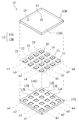
- the pump unit 10 includes a plate-shaped housing 13 having an inlet 11 and an outlet 12, a micropump 15 (see FIG. 3) housed in the housing 13, and a light emitting diode 18. And using a micropump 15 (see FIG. 3), the fluid is sucked from the inlet 11 and the sucked fluid flows out from the outlet 12.
- the housing 13 has an entrance side accommodation plate 13A and an exit side accommodation plate 13B.
- a concave portion 13K for attaching the micropump 15 is formed on the surface 13AS of the inlet side accommodation plate 13A.
- the recesses 13K are arranged in a lattice pattern.
- a recess for attaching the micropump 15 is also formed on the surface 13BS of the outlet side accommodation plate 13B.
- the concave portion provided on the surface 13BS is provided at a position facing the concave portion 13K when the receiving plates 13A and 13B are overlapped so that the surfaces 13AS and 13BS are aligned with each other.
- a storage space for the micropump 15 is formed by the recess 13K of the inlet side storage plate 13A and the recess of the outlet side storage plate 13B. Accordingly, by placing the micropump 15 in the recess provided in one of the accommodation plates 13A and 13B, the micropump 15 has a grid shape of m rows ⁇ n columns (for example, 4 rows ⁇ 4). Column). Then, the micro pumps 15 are built in the housing 13 in a state of being arranged in a lattice by overlapping the receiving plates 13A and 13B so that the surfaces 13AS and 13BS are aligned with each other.
- the plurality of micropumps 15 (pump group) built in the housing 13 are the most popular group 21 composed of the micropumps 15 arranged in the most popular (m1 row in the figure) and the most downstream row (m4 in the figure). Micro pumps arranged in the row direction (m2 row, m3 row in the figure) between the most downstream row group 24 composed of the micropumps 15 arranged in the row) and the most popular group 21 and the most downstream row group 24. Intermediate row groups 22 and 23 are formed.
- a fluid flow path is formed in the housing 13.
- the flow path is formed so that the suction port and the discharge port of the micropump 15 built in the housing 13 are connected and the fluid is conveyed from the inlet 11 to the outlet 12 in the housing 13. The flow path will be described later.
- the micropump 15 for example, the one proposed in Patent Document WO2008 / 069266 can be used. As shown in FIGS. 4 and 5, the micropump 15 includes a case 31 having a suction port 31A and a discharge port 31B, and a pump device that is built in the case 31 and conveys gas from the suction port 31A to the discharge port 31B. 32 and a power supply terminal 33 exposed to the outside of the case 31.
- the pump device 32 includes a piezoelectric element 32A that is electrically connected to the power supply terminal 33 and can be deformed by applying a voltage, and a deformation box 32B that can be deformed by the operation of the piezoelectric element.
- the deformation box 32B has a diaphragm 32BA and a vibrating wall 32BB.
- Diaphragm 32BA is provided in the portion of deformation box 32B that faces suction port 31A.
- the vibration wall 32BB is provided in a portion of the deformation box 32B that faces the discharge port 31B.
- a primary blower chamber 32K is formed between the diaphragm 32BA and the vibration wall 32BB.
- a piezoelectric element 32A is attached to the surface of the diaphragm 32BA facing the suction port 31A. Furthermore, an opening 32BD for moving the fluid inside and outside the primary blower chamber 32K is formed in the vibration wall 32BB at a position facing the discharge port 31B.
- the vibration wall 32BB resonates due to the movement of the fluid.
- the fluid is sucked from the suction port 31A by the vibration of the diaphragm 32BA and the vibration wall 32BB.
- the fluid sucked from the suction port 31A passes through the secondary blower chamber 32L and is discharged from the discharge port 31B.
- the micropump 15 is suitable for a blower application for transferring a fluid and can be transferred without using a check valve.
- the vibration frequency of the diaphragm 32BA is, for example, 1 kHz or more and preferably 18 kHz or more and 27 kHz or less. Moreover, it is preferable that the frequency of diaphragm 32BA is a non-audible area
- the micropump 15 includes a sensor unit 36 for detecting a failure of the pump device 32.
- the sensor unit 36 includes a pressure sensor that detects the static pressure P of the fluid at the discharge port 31B, and a flow rate sensor that detects the flow rate Q of the fluid at the discharge port 31B.
- the micropump 15 is formed in a plate shape and is extremely small (for example, about 20 mm long ⁇ 20 mm wide ⁇ about 2 mm thick). However, when the input sine wave is 15 Vpp (Volt peak to peak) and 26 kHz, the maximum is about 1 L / Minute fluid can be conveyed, and a maximum static pressure of 2 kPa can be obtained (see FIG. 6).
- the micropump 15 conveys the fluid by the vibration of the diaphragm 32BA by the piezoelectric element 32A, there is a limit to the volume of the fluid that can be conveyed, and the static pressure / flow rate characteristics tend to be as shown in FIG. Proportional multiplier is a negative linear function or similar).
- the flow rate Q is 0.5 L / min.
- the input sine wave is 10 Vpp and 20 Vpp, the amplitude of the piezoelectric element 32A changes, so that the flow rate Q and static pressure P corresponding to the input sine wave can be obtained. That is, when the input sine wave Vpp is smoothly changed, the flow rate Q and the static pressure P can be changed smoothly.
- the flow rate Q and the static pressure P can be changed by changing the frequency of the input sine wave. That is, when the frequency of the input sine wave is changed smoothly, the flow rate Q and the static pressure P can be changed smoothly.
- the flow rate Q and the static pressure P have upper limits depending on the capacity of the piezoelectric element 32A and the strength and durability of the components of the micropump 15. Usually used at rated Vpp and frequency.
- the micropump 15 may have a monomorph (unimofull) structure in which one piezoelectric element 32A is bonded to the diaphragm 32BA as described above, or the two piezoelectric elements 32A are bonded to each other to increase the vibration amount. It may have a bimofull structure.
- the structure of the micropump 15 may be an optimum one according to the purpose such as fluid conveyance. Note that the micropump 15 can convey gas without using a check valve, but instead of the micropump 15, a micropump provided with a check valve at the suction port or the discharge port may be applied.
- the housing 13 includes an external power supply terminal 37, a controller 38, and a wiring 39.
- the external power supply terminal 37 is provided so as to be exposed to the housing 13.
- the controller 38 and the wiring 39 are provided on the inlet side accommodation plate 13A.
- the wiring 39 electrically connects the external power supply terminal 37 and the controller 38.
- the bus 85H electrically connects the controller 38, the light-emitting diode 18, and the power supply terminal 33 provided in each micropump 15. Details of the controller 38 will be described later.
- the housing 13 has an inlet direct coupling mechanism, an outlet direct coupling mechanism, and a flow path forming mechanism that connects the inlet direct coupling mechanism and the outlet direct coupling mechanism.
- the inlet direct connection mechanism includes an inlet direct connection flow path 41 that directly connects the suction ports 31A of all the micropumps 15 belonging to the most popular group 21 (m1 row in the figure) and the inlets 11. is there.
- the inlet direct connection channel 41 is formed in the inlet side accommodation plate 13A.
- a switching valve 41Z is provided in the inlet direct connection flow path 41. The switching valve 41Z is in a parallel state in which the suction ports 31A and the inlets 11 of the plurality of micropumps 15 belonging to the most popular group 21 (m1 row in the figure) communicate with each other and the most popular group 21 (m1 row in the figure).
- any one of the micropumps 15 to which the micropump 15 belongs can be switched between a series state in which the suction port 31A and the inlet 11 communicate with each other.
- the suction ports 31A of all the micropumps 15 belonging to the most popular group 21 may be in communication with the inlet 11 or the most popular group 21 Among the micropumps 15 belonging to (line m1 in the figure), the suction ports 31A of some of the micropumps 15 communicate with the inlet 11 while the remaining suction ports 31A of the micropumps 15 do not communicate with the inlet 11 But you can.
- the outlet direct connection mechanism is an outlet direct connection flow path 42 that directly connects the discharge port 31B and the outlet 12 of the most downstream row group 24 (m4 row in the figure).
- the outlet direct connection flow path 42 is formed in the outlet side accommodation plate 13B.
- the flow path forming mechanism is formed on the inlet side accommodating plate 13A and the outlet side accommodating plate 13B.
- the flow path forming mechanism includes the switching valve 41 ⁇ / b> Z, the intermediate flow path 43, and the opening / closing mechanism provided in the intermediate flow path 43.
- the intermediate flow path 43 includes the most upstream discharge flow path 51B, the intermediate suction flow path 52A, the intermediate discharge flow path 52B, the intermediate suction flow path 53A, the intermediate discharge flow path 53B, and the most downstream suction. It has a mouth channel 54A, serial channels 61 to 63, and row bypass channels 71 to 73.
- the most upstream discharge port channel 51B connects the discharge ports 31B of all the micropumps 15 belonging to the most popular group 21 (m1 row in the figure).
- the intermediate suction port flow path 52A connects the suction ports 31A of all the micropumps 15 belonging to the intermediate row group 22 (m2 row in the figure), and the intermediate discharge port flow path 52B is connected to the intermediate row group 22 (in the figure).
- the discharge ports 31B of all the micropumps 15 belonging to (m2 line) are connected.
- the intermediate suction port channel 53A connects the suction ports 31A of all the micropumps 15 belonging to the intermediate row group 23 (m3 row in the figure), and the intermediate discharge port channel 53B is connected to the intermediate row group 23 ( The discharge ports 31B of all the micropumps 15 belonging to (m3 line in the figure) are connected.
- the most downstream suction passage 54A connects the suction ports 31A of all the micropumps 15 belonging to the most downstream row group 24 (m4 row in the figure).
- Each of the inlet channels 52A to 54A is connected to the inlet 11 via the switching valve 41Z and the inlet direct passage 41, and each of the outlet channels 51B to 53B is connected to the outlet 12 via the outlet direct passage 42. Connect with.
- the inlet channels 52A to 54A and the inlet 11 may communicate with each other regardless of the state of the switching valve 41Z. When the switching valve 41Z is in a parallel state, the communication switching valve 41Z is in a series state. If it is, it may be blocked.
- the inlet channel 52A is connected to the inlet direct channel 41 at the position P 52A (see FIG. 9), and the inlet channel 53A is connected at the position P 53A (see FIG. 9).
- the inlet channel 54A is connected to the channel 53A at a position P 53A .
- the discharge port channel 53B communicates with the outlet direct connection channel 42 at the position P 53B (see FIG. 9) and the discharge port channel 52B at the position P 52B (see FIG. 9).
- Discharge port channel 51B communicates with channel 52B at position P 52B (see FIG. 9).
- the serial flow path 61 connects the discharge port flow path 51B and the suction flow path 52A.
- the series channel 62 connects the discharge port channel 52B and the suction port channel 53A, and the series channel 63 connects the discharge port channel 53B and the suction port channel 54A.
- a valve 51Y is provided at a connection position between the discharge port channel 51B and the series channel 61.
- the valve 51Y has a parallel state in which the series flow path 61 is closed while opening the discharge flow path 51B on the downstream side (outlet 12 side) from the valve 51Y, and the discharge flow path on the downstream side (outlet 12 side) from the valve 51Y. Transition between a series state in which the series flow path 61 is opened while closing 51B is possible. In either the parallel state or the serial state, the discharge port channel 51B on the upstream side (discharge port 31B side) with respect to the valve 51Y remains open.
- a valve 52Y is provided at a connection position between the discharge port flow path 52B and the flow path 62
- a valve 53Y is provided at a connection position between the discharge port flow path 53B and the series flow path 63.
- the valve 52Y has a parallel state in which the discharge passage 52B on the downstream side (outlet 12 side) of the valve 52Y is opened and the series passage 62 is closed, and the discharge passage on the downstream side (outlet 12 side) of the valve 52Y. Transition is possible between a series state in which the series flow path 62 is opened while closing 52B. Note that, in either the parallel state or the serial state, the discharge port passage 52B on the upstream side (discharge port 31B side) of the valve 52Y remains open.
- valve 53Y has a parallel state in which the discharge passage 53B on the downstream side (outlet 12 side) of the valve 53Y is opened and the series passage 63 is closed, and the discharge on the downstream side (outlet 12 side) of the valve 53Y. It is possible to change between a series state in which the outlet channel 53B is closed and the series channel 63 is opened. Note that, in either the parallel state or the serial state, the discharge port channel 53B on the upstream side (discharge port 31B side) of the valve 53Y remains open.
- a valve 52X is provided at a connection position between the suction passage 52A and the series passage 61.
- the valve 52X has a parallel state in which another flow path is opened while closing the series flow path 61, and a serial state in which another flow path is opened while closing the suction flow path 52A on the upstream side (inlet 11 side) from the valve 52X.
- a valve 53X is provided at a connection position between the suction channel 53A and the series channel 62
- a valve 54X is provided at a connection position between the suction channel 54A and the series channel 63.
- the valve 53X has a parallel state in which another flow path is opened while closing the serial flow path 62, and a serial state in which another flow path is opened while closing the suction flow path 53A on the upstream side (inlet 11 side) from the valve 53X. In addition, it is possible to transition between a bypass state in which the inlet channel 53A on the downstream side of the valve 53X is closed and another channel is opened.
- the valve 54X has a parallel state in which another flow path is opened while closing the serial flow path 63, and a serial state in which another flow path is opened while closing the suction flow path 54A on the upstream side (inlet 11 side) from the valve 54X. In addition, it is possible to transition between a bypass state in which the inlet channel 54A on the downstream side of the valve 54X is closed and another channel is opened.
- the valve 81 is provided in the inlet direct connection channel 41 on the downstream side of the position P 52A .
- the valve 82 is provided in the inlet channel 52A downstream of the valve 52X, and the valve 83 is provided in the inlet channel 53A downstream of the valve 53X.
- the row bypass channel 71 connects the inlet channel 52A between the valve 82 and the valve 52X and the valve 81.
- the column bypass channel 72 connects the inlet channel 53A between the valve 83 and the valve 53X and the valve 82, and the column bypass channel 73 is the inlet channel between the micropump 15 and the valve 54X. 54A and valve 83 are connected.
- the valve 81 is in a normal state in which the other bypass channel is opened while closing the row bypass channel 71, in a bypass state in which the other channel is opened while closing the inlet direct connection channel 41 on the downstream side of the valve 81, and from the valve 81 In addition, it is possible to change between a closed state in which the upstream inlet direct connection channel 41 is closed and another channel is opened.
- the valve 82 includes a normal state in which the other bypass channel 72 is opened while closing the column bypass channel 72, a bypass state in which the other inlet channel 52A is closed downstream of the valve 82 and another channel is opened, and In addition, it is possible to transition between a closed state in which the other inlet passage is opened while closing the upstream inlet passage 52A.
- the valve 83 has a normal state in which the other bypass channel is opened while closing the row bypass channel 73, a bypass state in which the other channel is opened while closing the inlet channel 53A on the downstream side of the valve 83, and from the valve 83. In addition, it is possible to change between a closed state in which the other inlet passage is opened while closing the upstream inlet passage 53A.
- the opening / closing mechanism includes valves 52X to 54X, 51Y to 53Y, and 81 to 83.
- the first flow path forming part is configured by the suction flow paths 52A to 54A and the valves 52X to 54X
- the second flow path forming part is configured by the series flow paths 61 to 63 and the valves 51Y to 53Y.
- the three flow path forming part is constituted by the discharge port flow paths 51B to 53B and the valves 51Y to 53Y.
- the row bypass flow path is constituted by the suction port flow paths 52A to 54A.
- a sensor unit 45 is provided in the vicinity of the outlet 12 in the outlet direct connection flow path 42.
- the sensor unit 45 includes a pressure sensor 45P that detects the static pressure P of the fluid in the vicinity of the outlet 12 in the outlet direct connection flow path 42, and a flow sensor 45Q that detects the flow rate Q of the fluid in the vicinity of the outlet 12 in the direct outlet flow path 42. And have.
- the controller 38 includes a CPU 85A, a first storage medium 85B, a second storage medium 85C, a third storage medium 85D, an input device 85E, a display device 85F, an input / output interface 85G, and a bus 85H as hardware configurations (see FIG. 10).
- the CPU 85A is a so-called central processing unit, and implements various functions of the controller 38 by executing various programs.
- the first storage medium 85B is a so-called RAM (Random Access Memory) and is a memory used as a work area for the CPU 85A.
- the second storage medium 85C is a so-called ROM (read only memory), and is a memory for storing a basic OS executed by the CPU 85A.
- the third storage medium 85D includes a hard disk device with a built-in magnetic disk, a disk device that houses a CD, DVD, or BD, a non-volatile semiconductor flash memory device, and the like.
- the input device 85E is an input key, a keyboard, and a mouse, and is a device for inputting various information.
- the display device 85F is a display and displays various operation states.
- the input / output interface 85G is connected to the valves 52X to 54X, 51Y to 53Y, 81 to 83, the switching valve 41Z, each micropump 15 (see FIG. 8), and each sensor unit 36, 45 (see FIGS. 5 and 9).
- the input / output interface 85G can acquire data such as a program from an external personal computer and can output measurement results to the personal computer.
- the bus 85H is a wiring for integrally connecting the CPU 85A, the first storage medium 85B, the second storage medium 85C, the third storage medium 85D, the input device 85E, the display device 85F, the input / output interface 85G, and the like. It is.
- the wiring 85H is preferably formed so as to be exposed in the recess 13K (see FIG. 3) provided in the inlet side accommodation plate 13A (see FIG. 9). Accordingly, when the micropump 11 is accommodated in the recess 13K, the external power supply terminal 37 of the micropump 11 accommodated in the recess 13K is electrically connected to the wiring 85. Thus, the wiring to the micropump 11 can be performed by accommodating the micropump 11 in the recess 13K.
- the wiring 85H should just be formed so that it may be exposed to at least any one recessed part among the entrance side accommodation board 13A and the exit side accommodation board 13B.
- (Plate spring, coil spring, etc.) 85J may be provided so as to be exposed.
- the urging member has conductivity, the urging member and the wiring 85H may be electrically connected.
- the controller 38 When the control program stored in the controller 38 is executed by the CPU 85A, the controller 38, as shown in FIG. 11, the pump power supply control unit 94, the failure detection unit 95, the pump substitution control unit 96, and the flow path formation. It functions as a control unit 97 and a warning notification unit 98.
- the pump power supply control unit 94 supplies power to the pump device 32 of the predetermined micropump 15 in accordance with operation conditions set in advance by operating the input device 85E.
- the operating condition refers to, for example, a condition in which a fluid having a desired static pressure P and a desired flow rate Q is discharged from the outlet 12 (see FIG. 5) of the pump unit 10.
- the failure detection unit 95 reads the sensing signal from each sensor of the sensor unit 36 provided in the micropump 15 and determines whether or not the measured value indicated by the sensing signal exceeds the allowable range.
- the allowable range is a value between the upper limit value and the lower limit value set by operating the input device 85E.
- the upper limit value and the lower limit value are set such that the static pressure P and the flow rate Q of the fluid discharged from the micropump 15 that cannot exhibit the intended performance such as deterioration or failure of the pump device 32 are out of the allowable range. .
- the failure detection unit 95 determines that the micropump 15 in which the measurement value is measured is in a normal state, and the measurement value from each sensor When at least one of them exceeds the allowable range, the micropump 15 in which the measured value is measured is determined as a failure state. Further, the failure detection unit 95 outputs a failure signal.
- the failure signal includes information on the identifier of the micropump 15 determined to be a failure (for example, the micropump arranged in the i-th row ⁇ j-th row).
- the pump substitution control unit 96 determines whether or not a failure signal is output from the failure detection unit 95.
- the pump substitution control unit 96 can receive a failure signal.
- the pump substitution control unit 96 can read the power supply list information of the micropump 15 supplied with power by the pump power supply control unit 94 from the pump power supply control unit 94. Further, the pump substitution control unit 96 determines the presence or absence of the micropump 15 of the standby micropump 15.
- the standby state is a state that is not determined to be a failure (normal state), and is a state where power supply is stopped (power supply stop state).
- the flow path formation control unit 97 refers to the sensing signals from the sensor units 36 and 46, and The valves 52X to 54X, 51Y to 53Y, and 81 to 83, which are opening and closing mechanisms, are opened and closed so that the flow rate Q and the static pressure P at the outlet 12 become predetermined values or approach each other.
- the warning notification unit 98 controls the light emitting diode 18 to be turned on and off. Note that the warning device is not limited to the light emitting diode 18, and a buzzer or the like may be used.
- the switching valve 41Z When the switching valve 41Z is set in a parallel state, the valves 81 to 83 are set in a normal state, and the valves 52X to 54X and 51Y to 53Y are set in a parallel state by the flow path formation control unit 97, the inlet 11 enters.
- the fluid is branched for each suction port of the micropump 15 and enters the micropump 15.
- the fluids exiting from the discharge port of the micropump 15 merge again and exit from the outlet 12 (see FIG. 13).
- the pump unit 10 enters a state where the flow rate Q of the fluid exiting from the outlet 12 increases in preference to the static pressure P (flow rate priority transport state).
- the switching valve 41Z is set in a parallel state
- the valves 81 to 83 are set in a normal state
- the valves 52X to 54X and 51Y to 52Y are in a serial state
- the valve 53Y is in a parallel state by the flow path formation control unit 97.
- the flow rate Q and static pressure P of the fluid exiting the outlet 12 take values between the previous two examples.
- the pump device 32 if the pump device 32 is in a state in which the pump device 32 does not operate normally (hereinafter referred to as a failure state), the flow rate Q of the fluid that exits from the outlet 12 And the static pressure P cannot be controlled with high accuracy.
- micropumps 15 are arranged in a grid (4 rows ⁇ 4 columns), all the micropumps 15 located in the fourth column and the fourth row are used as spare micropumps. 15 is assumed.
- the pump power supply control unit 94 supplies power only to the micropumps 15 in the first to third rows and the first to third columns.
- the micropumps 15 in the 1st to 3rd rows ⁇ 1st to 3rd columns are in an operating state, and the spare micropump 15 is in a power supply stopped state.
- the flow path formation control unit 97 sets the switching valve 41Z in a parallel state, the first to third rows of valves 81 to 83 in a normal state, the fourth row of valves 81 to 83 in a blocked state, and the first to third rows.
- the valves 51Y to 52Y are set in series, the first to third rows of valves 53Y are set in parallel, and the first to third rows of valves 52X to 54X are set in series.
- first to third row valves 54X, the fourth row valves 52X to 54X, and the valves 51Y to 53Y may be set in series. Thereby, the pump unit 10 is in a state in which the static pressure P of the fluid exiting from the outlet 12 increases in preference to the flow rate Q.
- the failure detection unit 95 reads a sensing signal from each sensor unit 36.
- the reading timing of the sensing signal may be every fixed period or may be continuous.
- the failure detection unit 95 determines whether or not the measurement value indicated by the read sensing signal is out of the allowable range. When each measured value is within the allowable range, the failure detection unit 95 determines that the micropump 15 that has read the sensing signal is in a normal state. On the other hand, when each measured value is out of the allowable range, the failure detection unit 95 determines that the micropump 15 that has read the sensing signal is in a failure state. If it is determined that there is a faulty micro pump 15, the failure detection unit 95 outputs a failure signal.
- the pump substitution control unit 96 determines whether or not a failure signal is output from the failure detection unit 95. When the pump substitution control unit 96 determines that “a failure signal is output from the failure detection unit 95”, “whether there is a standby micropump 15 among the micropumps 15 built in the pump unit 10”. judge. When the pump substitution control unit 96 determines that there is a standby micropump 15, the pump power supply control unit 94 selects the micropump 15 selected from the standby micropumps 15 (hereinafter, the selected micropump 15). The power supply is started. In addition, it is preferable that the pump electric power feeding control part 94 stops the electric power feeding of the micropump 15 determined to be in a failure state.
- the flow path formation control unit 97 opens and closes the valves 51Y to 53Y, 52X to 54X, and 81 to 83 so that the fluid flows to the selected micropump 15 instead of the micropump 15 determined to be faulty. I do. Thereby, even if the micro pump 15 in a fault state exists in the pump unit 10, a fluid having a desired static pressure P and a desired flow rate Q can be discharged from the outlet 12 of the pump unit 10.
- the flow path formation control unit 97 selects an arbitrary micropump 15 from the standby micropumps 15 in the standby state.
- the flow path formation control unit 97 bypasses the valve 52X in the third row and the valve 53X in the fourth row.
- the fourth row valve 52X and the third row valve 53X are set in a parallel state
- the fourth row valve 52Y is set in a series state
- the fourth row valve 82 is set in a normal state.
- the fluid that has passed through the micropump 15 in the first row ⁇ third column passes through the micropump 15 in the second row ⁇ fourth column instead of the micropump 15 in the second row ⁇ third column. It passes through the micropump 15 in the third row ⁇ third column (see FIG. 15). For this reason, a fluid having an intended flow rate Q and an intended static pressure P can be discharged from the outlet 12.
- the flow path formation control unit 97 puts the valve 82 in the third row into the bypass state and sets the valve in the third row 83 is set to the normal state, and the valves 53Y and 54X in the third row are set in series.
- the third row of valves 53X is preferably in series.
- the warning notification unit 98 notifies the abnormal state of the pump unit 10 by controlling the light emitting diode 18 to be turned on and off. be able to. Thereby, use of the pump unit 10 which cannot output the fluid of the desired static pressure P and the desired flow volume Q can be avoided.
- the micropumps 15 are arranged in a lattice pattern, and the flow path forming mechanism, that is, the intermediate flow path 43 and the opening / closing mechanism (each valve) provided in the intermediate flow path 43, It becomes possible to control the series connection and the parallel connection of each micropump 15 in a rational combination. As a result, even if the micropump 15 is used alone, the flow rate and the static pressure are insufficient, a plurality of micropumps 15 can be used in combination, so that it can be used in the same manner as a conventional blower or syringe pump.
- the micropump 15 since the micropump 15 has a small size, even if a plurality of the micropumps 15 are arranged, the micropump 15 can be configured to be smaller and lighter than conventional blowers.
- the control configuration is also extremely high. Can be concise.
- a conventional blower or syringe pump if one of them fails, the entire fluid transport will be delayed, but according to the pump unit 10 described above, even if each micropump 15 fails, Since it can be supplemented by another micropump 15, reliability and safety can be improved.
- the number of micropumps 15 in the downstream line is equal or smaller than the number of micropumps 15 belonging to the epidemic.
- useless operation of the micropump 15 is suppressed, so that power consumption can be reduced, which is particularly suitable for battery-driven applications, for example.
- connection relation is collectively switched for the whole of the plurality of micropumps 15 arranged in each row.
- the configuration of the valve is simplified and the maintainability is improved.
- the inlet 11 of the pump unit 10 may be one or plural.
- the plurality of inlets 11 may be connected to the inlet direct connection channel 41 or may be directly connected to the micropump 15 belonging to the most popular group 21.
- the number of intermediate row groups may be one, or three or more.
- the most popular group 21, the middle row groups 22, 23, and the most downstream row group 24 are arranged in this order in the housing 13, but the present invention is not limited to this.
- the order of the most downstream row group 24, the middle row groups 22, 23, the order of the most downstream row group 24, the middle row groups 22, 23, the most popular group 21, and the like may be used.
- the micropumps 15 are arranged in a grid pattern in the housing 13, but the present invention is not limited to this, and the micropumps 15 may be arranged in one row or one column.
- the micropump 15 is fitted to the housing 13, but the present invention is not limited to this, and the micropump 15 and the housing 13 may be integrally formed.
- the micropumps 15 are arranged in a grid pattern on a plane, but the present invention is not limited to this, and a plurality of micropumps 15 may be arranged to overlap each other.
- the micropump 15 may be stacked so that the inlet 11 of the second micropump 15 is positioned above the outlet 12 of the first micropump 15 (see FIGS. 17 to 20).
- the 17 to 18 includes a casing 13 having an inlet 11 and an outlet 12 and a pump unit 15 accommodated in the casing 13.
- the housing 13 having the pump unit housing hole 13X for housing the pump unit 15 includes a first housing forming block 13L and a second housing forming block 13R. Each of the first housing forming block 13L and the second housing forming block 13R is formed with a predetermined recess.
- the pump unit accommodation hole 13X is formed by combining the first housing forming block 13L and the second housing forming block 13R so that the recesses face each other.
- the micropumps 15A, 15B, and 15C arranged in this order from the inlet 11 to the outlet 12 in the housing 13, and the micropump 15A and the micropump 15B are arranged.
- a flow path block 13SA disposed between the two and a flow path block 13SB disposed between the micro pump 15B and the micro pump 15C.
- the housing 13 is formed with an inlet direct flow path 41 that connects the suction port 31A and the inlet 11 of the micropump 15A, and an outlet direct flow path 42 that connects the discharge port 31B and the outlet 12 of the micropump 15C.
- the direct inlet passage 41 includes a direct passage 41A that directly connects the suction port 31A and the inlet 11 of the micropump 15A, and a branch passage 41B that branches from the direct passage 41A.
- the branch path 41B extends to the vicinity of the suction port 31A of the micropump 15C so as to extend along the micropumps 15A, 15B, and 15C.
- the outlet direct connection flow path 42 includes a direct connection path 42A that directly connects the discharge port 31B and the outlet 12 of the micro pump 15C, and a branch path 42B that branches from the direct connection path 42A.
- the branch path 42B extends to the vicinity of the discharge port 31B of the micropump 15A along the micropumps 15C, 15B, 15A.
- the flow path block 13SA is formed in a rectangular parallelepiped shape.
- the flow path block 13SA includes a series flow path 90A that directly connects the discharge port 31B of the micropump 15A and the suction port 31A of the micropump 15B, a series valve 90AB that opens and closes the series flow path 90A, and a discharge port more than the series valve 90AB.
- a suction side parallel flow path 91A that directly connects the passage 90A and the branch path 41B and a suction side parallel valve 91AB that opens and closes the suction side parallel flow path 91A are formed.
- illustration of each valve 90AB, 91AB, and 92AB in FIG. 20 is abbreviate
- the flow path block 13SB is the same as the flow path block 13SA, that is, formed in a rectangular parallelepiped shape, and a series flow path 90B that directly connects the discharge port 31B of the micropump 15B and the suction port 31A of the micropump 15C.
- a series valve 90BB that opens and closes the passage 90B, a discharge side parallel passage 92B that directly connects the series passage 90B and the branch passage 42B closer to the discharge port 31B than the series valve 90BB, and a discharge side that opens and closes the discharge side parallel passage 92B
- a parallel valve 92BB a suction side parallel flow path 91B that directly connects the serial flow path 90B and the branch path 41B closer to the suction port 31A than the series valve 90BB, a suction side parallel valve 91BB that opens and closes the suction side parallel flow path 91B, Is formed.
- the serial flow path 90A penetrates from the discharge port side surface 13AL of the flow path block 13SA facing the discharge port 31B of the micropump 15A to the suction port side surface 13AU of the flow path block 13SA facing the suction port 31A of the micropump 15B. It is formed.
- the discharge side parallel flow path 92A is formed by the groove 13LM formed in the discharge port side surface 13AL and the micro pump 15A.
- the suction side parallel flow path 91A is formed by the groove 13UM formed in the suction port side surface 13AU and the micro pump 15A.
- the serial flow path 90B penetrates from the discharge port side surface 13BL of the flow path block 13SB facing the discharge port 31B of the micropump 15B to the suction port side surface 13BU of the flow path block 13SB facing the suction port 31A of the micropump 15C. To be formed.
- the discharge side parallel flow path 92B is formed by the groove formed on the discharge port side surface 13BL and the micro pump 15A.
- the housing of the micropump 15 ⁇ / b> C and the suction port side surface 13 ⁇ / b> BU are in contact with each other, so that a suction side parallel flow path 91 ⁇ / b> B is formed by the groove formed in the suction port side surface 13 ⁇ / b> BU and the micropump 15 ⁇ / b> C.
- the switching valve 41Z, the series valves 90AB and 90BB, the suction side parallel valves 91AB and 91BB, and the discharge side parallel valves 92AB and 92BB are opened and closed by the controller 38 (see FIG. 7).
- the switching valve 41Z is set in a parallel state, the series valves 90AB and 90BB are closed, and the suction side parallel valves 91AB and 91BB and the discharge side parallel valves 92AB and 92BB are opened (see FIG. 19).
- the fluid entering from the inlet 11 is distributed via the inlet direct connection channel 41, the suction side parallel channel 91A, and the suction side parallel channel 91B, and the distributed fluid is the suction ports 31A of the micropumps 15A to 15C, respectively. Inhaled.
- the pump device 32 In each of the micro pumps 15A to 15C, the pump device 32 (see FIG. 5) compresses the fluid sucked from the suction port 31A.
- the fluid compressed by the micropumps 15A to 15C exits from the discharge port 31B, joins via the discharge side parallel flow path 92A, the discharge side parallel flow path 92B, and the outlet direct connection flow path 42, and then the outlet 12 Get out of.
- the switching valve 41Z is set in a series state, the series valves 90AB and 90BB are set in an open state, and the suction side parallel valves 91AB and 91BB and the discharge side parallel valves 92AB and 92BB are set in a closed state (see FIG. 18).
- the fluid that has entered from the inlet 11 is sucked into the suction port 31A of the micropump 15A through the inlet direct connection channel 41.
- the pump device 32 (see FIG. 5) compresses the fluid sucked from the suction port 31A.
- the fluid compressed by the micropump 15A exits from the discharge port 31B and is sucked into the suction port 31A of the micropump 15B through the serial flow path 90A.
- the fluid sucked from the suction port 31A of the micropump 15B is compressed by the pump device 32 (see FIG. 5), and then sucked into the suction port 31A of the micropump 15C via the discharge port 31B and the serial channel 90B. .
- the fluid sucked from the suction port 31A of the micropump 15C is compressed by the pump device 32 (see FIG. 5), and then exits from the outlet 12 via the discharge port 31B and the outlet direct connection channel.
- the static pressure P and the flow rate Q of the fluid flowing out from the outlet 12 are opened and closed by the switching valve 41Z, the series valves 90AB and 90BB, the suction side parallel valves 91AB and 91BB, and the discharge side parallel valves 92AB and 92BB. Can be adjusted as appropriate.
- the discharge side parallel flow path 92A is formed by the groove 13LM and the micropump 15A formed in the discharge port side surface 13AL, it is possible to reduce the trouble of forming the discharge side parallel flow path 92A.
- the suction side parallel flow path 91A is formed by the groove 13UM and the micropump 15A formed in the suction side surface 13AU, the labor for forming the suction side parallel flow path 91A can be reduced.
- each of the flow path forming plates 13AA to 13AD has a through hole formed in a thickness direction at a predetermined position. Further, each of the flow path forming plates 13AA to 13AD has a groove at a predetermined position on the surface facing the other flow path forming plate.
- the outlet side accommodation plate 13B is preferably formed by the flow path forming plates 13BA to 13BB.
- Each of the flow path forming plates 13BA to 13BB has a through hole formed in the thickness direction and a groove formed on a surface facing the other flow path forming plate at predetermined positions.
- the respective flow paths 42, 51B to 53B and downstream of 61 to 63 of the respective flow paths are formed by through holes and grooves formed in the flow path forming plates 13BA to 13BB. A part is formed.
- the breathing assistance device 700 includes a flow path 702 through which breathing gas passes, and an expiratory nozzle 704 and an inhalation nozzle that are disposed in the flow path 702 and can release acceleration air in the exhalation direction and the inhalation direction, respectively.
- 706 a pump unit 10 disposed on the outer surface of the flow path 702 along the circumferential direction, and a battery 710 that drives the pump unit 10.
- Venturi walls 720 are disposed in the vicinity of the exhalation and inhalation nozzles 704 and 706 disposed in the flow path 702, respectively.
- the battery 710 can be omitted by disposing the battery 710 at a remote location or connecting a power supply line.
- a breathing switching valve 725 is disposed at the outlet 12 of the pump unit 10 (see FIG. 1; hereinafter also referred to as an integrated discharge port).
- the breath switching valve 725 switches between a case where the air discharged from the integrated discharge port is discharged from the exhalation nozzle 704 and a case where the air is discharged from the intake nozzle 706.
- FIG. 23A when the air is discharged from the exhalation nozzle 704, the exhalation side becomes a negative pressure state by spreading the air by the venturi wall 720, and carbon dioxide discharged from the inhalation side (lung side) is drawn in. And let it flow in the direction of exhalation. As a result, exhalation operation can be assisted.
- FIG. 23A when the air is discharged from the exhalation nozzle 704, the exhalation side becomes a negative pressure state by spreading the air by the venturi wall 720, and carbon dioxide discharged from the inhalation side (lung side) is drawn in. And let it flow in the direction of exhalation. As
- the respiratory assistance device 700 since the miniaturized pump unit 10 is directly fixed to the piping itself constituting the flow path 702, the respiratory assistance device 700 can be configured extremely compactly. Furthermore, since the flow path 702 and the pump unit 10 are integrated, even if the flow path 702 moves in conjunction with the movement of the user's body, the flow path 702 and the pump unit 10 move together. In addition, the connection between the intake nozzles 704 and 706 and the pump unit 10 is not interrupted. Therefore, the stability of the breathing assistance operation is increased and the user can easily move the body.
- the respiratory assistance device 700 can be used continuously with the intubation tube inserted from the user's mouth toward the trachea.
- the nasal mask 830 is used.
- the flow path 702 can be connected to and used.
- a case where one pump unit 10 is switched by the breath switching valve 725 and supplied to the exhalation nozzle or the intake nozzle is illustrated, but two pump units 10 are prepared, and the exhalation nozzle and the inspiration nozzle are respectively provided. You may make it connect with a nozzle.
- pump unit and the respiratory assistance device of the present invention are not limited to the above-described embodiments, and it goes without saying that various changes can be made without departing from the scope of the present invention.
- the pump unit of the present invention can be used for various purposes other than the respiratory assistance device.
- the respiratory assistance apparatus of this invention can be utilized for the purpose of respiratory assistance of various living things.
Abstract
L'invention concerne une unité (10) de pompe comportant un carter (13) muni d'une entrée (11) et d'une sortie (12) destinées à un fluide, et un groupe de pompes constitué de micro-pompes (15) alignées à l'intérieur du carter (13) et utilisées pour refouler par la sortie (12) le fluide entrant par l'entrée (11). Le groupe de pompes comporte une micro-pompe (15) positionnée au niveau de la plus haute coulée (m1), une micro-pompe (15) positionnée au niveau de la plus basse coulée (m4), et des micro-pompes (15) positionnées au milieu (m2-m3). Le carter (13) est muni d'une conduite (41) de liaison directe à l'entrée servant à relier directement l'entrée (11) à un orifice (31A) d'admission de la micro-pompe (15) positionnée au niveau de la plus haute coulée, d'une conduite (42) de liaison directe à la sortie servant à relier directement la sortie (12) à un orifice (31B) de refoulement de la micro-pompe (15) positionnée au niveau de la plus basse coulée, et un mécanisme de formation de conduite capable d'alterner entre un état où les micro-pompes (15) sont reliées en série et un état où les micro-pompes (15) sont reliées en parallèle.
Priority Applications (4)
| Application Number | Priority Date | Filing Date | Title |
|---|---|---|---|
| US14/390,104 US20150059749A1 (en) | 2012-04-02 | 2013-04-01 | Pump unit and respiratory assistance device |
| EP16163481.1A EP3064773B1 (fr) | 2012-04-02 | 2013-04-01 | Unité de pompe et dispositif d'assistance respiratoire |
| EP13771805.2A EP2835535B1 (fr) | 2012-04-02 | 2013-04-01 | Unité de pompe, dispositif d'assistance respiratoire |
| ES13771805.2T ES2592706T3 (es) | 2012-04-02 | 2013-04-01 | Unidad de bomba, dispositivo de asistencia respiratoria |
Applications Claiming Priority (2)
| Application Number | Priority Date | Filing Date | Title |
|---|---|---|---|
| JP2012083615A JP5636555B2 (ja) | 2012-04-02 | 2012-04-02 | ポンプユニット、呼吸補助装置 |
| JP2012-083615 | 2012-04-02 |
Publications (1)
| Publication Number | Publication Date |
|---|---|
| WO2013151014A1 true WO2013151014A1 (fr) | 2013-10-10 |
Family
ID=49300497
Family Applications (1)
| Application Number | Title | Priority Date | Filing Date |
|---|---|---|---|
| PCT/JP2013/059959 WO2013151014A1 (fr) | 2012-04-02 | 2013-04-01 | Unité de pompe, dispositif d'assistance respiratoire |
Country Status (5)
| Country | Link |
|---|---|
| US (1) | US20150059749A1 (fr) |
| EP (2) | EP2835535B1 (fr) |
| JP (1) | JP5636555B2 (fr) |
| ES (1) | ES2592706T3 (fr) |
| WO (1) | WO2013151014A1 (fr) |
Families Citing this family (23)
| Publication number | Priority date | Publication date | Assignee | Title |
|---|---|---|---|---|
| JP5636555B2 (ja) | 2012-04-02 | 2014-12-10 | 株式会社メトラン | ポンプユニット、呼吸補助装置 |
| JP6326569B2 (ja) * | 2014-03-26 | 2018-05-23 | 株式会社メトラン | 呼吸補助装置 |
| DE102014111528B3 (de) * | 2014-08-13 | 2015-07-09 | Carefusion Germany 234 Gmbh | Atemluftmessvorrichtung |
| SE541352C2 (en) * | 2015-06-03 | 2019-08-13 | Apr Tech Ab | Microfluidic array |
| DE102015224619A1 (de) * | 2015-12-08 | 2017-06-08 | Fraunhofer-Gesellschaft zur Förderung der angewandten Forschung e.V. | Mikrodosiersystem |
| WO2017135206A1 (fr) * | 2016-02-01 | 2017-08-10 | 株式会社村田製作所 | Dispositif de régulation de gaz |
| DE102016009833A1 (de) * | 2016-08-15 | 2018-02-15 | Drägerwerk AG & Co. KGaA | Vorrichtung zum Beatmen eines Patienten und Verfahren zum Betreiben der Vorrichtung |
| DE102016013740A1 (de) * | 2016-11-17 | 2018-05-17 | Drägerwerk AG & Co. KGaA | System zum Beatmen von Patienten |
| WO2018108715A1 (fr) * | 2016-12-13 | 2018-06-21 | Koninklijke Philips N.V. | Masque avec apport d'air primaire et secondaire |
| CN110709606B (zh) | 2017-06-01 | 2020-09-18 | 株式会社村田制作所 | 压力控制装置和压力利用装置 |
| WO2019028409A1 (fr) * | 2017-08-04 | 2019-02-07 | Clean Energy Labs, Llc | Système de pompe/transducteur à membrane à électroaimant et procédés de fabrication et d'utilisation associés |
| TWI689665B (zh) * | 2017-09-15 | 2020-04-01 | 研能科技股份有限公司 | 氣體輸送裝置 |
| TWI654374B (zh) * | 2017-09-29 | 2019-03-21 | 研能科技股份有限公司 | 流體系統 |
| TWI653394B (zh) * | 2017-09-29 | 2019-03-11 | 研能科技股份有限公司 | 流體系統 |
| TWI653395B (zh) * | 2017-09-29 | 2019-03-11 | 研能科技股份有限公司 | 流體系統 |
| TWI650284B (zh) * | 2017-09-30 | 2019-02-11 | Microjet Technology Co., Ltd | 流體裝置之控制方法 |
| CN109590032B (zh) * | 2017-09-30 | 2021-09-07 | 研能科技股份有限公司 | 流体装置的控制方法 |
| TWI646262B (zh) | 2017-10-27 | 2019-01-01 | 研能科技股份有限公司 | 氣體輸送裝置 |
| CN109882386B (zh) * | 2019-03-01 | 2020-05-26 | 浙江师范大学 | 一种阵列式微型气体压缩机 |
| IT201900005808A1 (it) | 2019-04-15 | 2020-10-15 | St Microelectronics Srl | Dispositivo mems a micropompa per la movimentazione o eiezione di un fluido, in particolare microsoffiante o flussimetro |
| DE102019004450B4 (de) | 2019-06-26 | 2024-03-14 | Drägerwerk AG & Co. KGaA | Mikropumpensystem und Verfahren zur Führung eines kompressiblen Fluids |
| WO2021130583A1 (fr) * | 2019-12-23 | 2021-07-01 | Kci Licensing, Inc. | Système de soupape d'optimisation de pompe |
| WO2024068318A1 (fr) * | 2022-09-27 | 2024-04-04 | Koninklijke Philips N.V. | Systèmes et procédés d'accélération de capacité de pression et de débit dans des systèmes de pompe à fluide |
Citations (6)
| Publication number | Priority date | Publication date | Assignee | Title |
|---|---|---|---|---|
| JPS49118106U (fr) * | 1973-01-30 | 1974-10-09 | ||
| JPH04119373U (ja) * | 1991-04-11 | 1992-10-26 | 日立工機株式会社 | 真空排気装置 |
| JP2004150329A (ja) * | 2002-10-30 | 2004-05-27 | Erc:Kk | 真空装置 |
| JP2006130320A (ja) * | 2004-11-05 | 2006-05-25 | Air Products & Chemicals Inc | 気道陽圧療法のための装着可能システム |
| WO2008069266A1 (fr) | 2006-12-09 | 2008-06-12 | Murata Manufacturing Co., Ltd. | Micro-ventilateur piézoélectrique |
| JP2010203349A (ja) * | 2009-03-04 | 2010-09-16 | Konica Minolta Holdings Inc | マイクロポンプユニット |
Family Cites Families (14)
| Publication number | Priority date | Publication date | Assignee | Title |
|---|---|---|---|---|
| US5431545A (en) * | 1993-12-02 | 1995-07-11 | Praxair Technology, Inc. | Pumper system for in-situ pigging applications |
| US6106245A (en) * | 1997-10-09 | 2000-08-22 | Honeywell | Low cost, high pumping rate electrostatically actuated mesopump |
| US6179586B1 (en) * | 1999-09-15 | 2001-01-30 | Honeywell International Inc. | Dual diaphragm, single chamber mesopump |
| US6752601B2 (en) * | 2001-04-06 | 2004-06-22 | Ngk Insulators, Ltd. | Micropump |
| WO2004076859A2 (fr) * | 2003-02-24 | 2004-09-10 | Mark Banister | Systeme de commande de pompe active par impulsion |
| AU2004228678A1 (en) * | 2003-04-03 | 2004-10-21 | Fluidigm Corp. | Microfluidic devices and methods of using same |
| US7336486B2 (en) * | 2005-09-30 | 2008-02-26 | Intel Corporation | Synthetic jet-based heat dissipation device |
| JP5082049B2 (ja) * | 2006-09-26 | 2012-11-28 | セイコーエプソン株式会社 | 流体噴射装置および手術具 |
| CN101211307A (zh) * | 2006-12-29 | 2008-07-02 | 鸿富锦精密工业(深圳)有限公司 | 主板水泵失效报警电路 |
| DE502007003785D1 (de) * | 2007-11-16 | 2010-06-24 | Linde Ag | Verfahren zum Ansteuern einer Pumpenanordnung und Pumpenanordnung |
| EP2469089A1 (fr) * | 2010-12-23 | 2012-06-27 | Debiotech S.A. | Procédé de contrôle électronique et système pour pompe piézo-électrique |
| JP4934750B1 (ja) * | 2011-05-31 | 2012-05-16 | 株式会社メトラン | ポンプユニット、呼吸補助装置 |
| JP5636555B2 (ja) | 2012-04-02 | 2014-12-10 | 株式会社メトラン | ポンプユニット、呼吸補助装置 |
| US20140094727A1 (en) * | 2012-09-28 | 2014-04-03 | Covidien Lp | Compression device pumping |
-
2012
- 2012-04-02 JP JP2012083615A patent/JP5636555B2/ja active Active
-
2013
- 2013-04-01 US US14/390,104 patent/US20150059749A1/en not_active Abandoned
- 2013-04-01 EP EP13771805.2A patent/EP2835535B1/fr active Active
- 2013-04-01 EP EP16163481.1A patent/EP3064773B1/fr active Active
- 2013-04-01 ES ES13771805.2T patent/ES2592706T3/es active Active
- 2013-04-01 WO PCT/JP2013/059959 patent/WO2013151014A1/fr active Application Filing
Patent Citations (6)
| Publication number | Priority date | Publication date | Assignee | Title |
|---|---|---|---|---|
| JPS49118106U (fr) * | 1973-01-30 | 1974-10-09 | ||
| JPH04119373U (ja) * | 1991-04-11 | 1992-10-26 | 日立工機株式会社 | 真空排気装置 |
| JP2004150329A (ja) * | 2002-10-30 | 2004-05-27 | Erc:Kk | 真空装置 |
| JP2006130320A (ja) * | 2004-11-05 | 2006-05-25 | Air Products & Chemicals Inc | 気道陽圧療法のための装着可能システム |
| WO2008069266A1 (fr) | 2006-12-09 | 2008-06-12 | Murata Manufacturing Co., Ltd. | Micro-ventilateur piézoélectrique |
| JP2010203349A (ja) * | 2009-03-04 | 2010-09-16 | Konica Minolta Holdings Inc | マイクロポンプユニット |
Non-Patent Citations (1)
| Title |
|---|
| See also references of EP2835535A4 |
Also Published As
| Publication number | Publication date |
|---|---|
| EP2835535A4 (fr) | 2015-03-25 |
| EP2835535A1 (fr) | 2015-02-11 |
| JP2013213421A (ja) | 2013-10-17 |
| US20150059749A1 (en) | 2015-03-05 |
| EP3064773A1 (fr) | 2016-09-07 |
| EP2835535B1 (fr) | 2016-06-29 |
| EP3064773B1 (fr) | 2019-06-12 |
| JP5636555B2 (ja) | 2014-12-10 |
| ES2592706T3 (es) | 2016-12-01 |
Similar Documents
| Publication | Publication Date | Title |
|---|---|---|
| JP5636555B2 (ja) | ポンプユニット、呼吸補助装置 | |
| JP4934750B1 (ja) | ポンプユニット、呼吸補助装置 | |
| JP5417561B2 (ja) | 呼気弁及び呼吸補助装置 | |
| JP6273418B2 (ja) | ポンプユニット、呼吸補助装置 | |
| WO2013157517A1 (fr) | Dispositif d'ouverture/fermeture et appareil d'assistance respiratoire | |
| CN103501848A (zh) | 呼吸设备 | |
| JP4934751B1 (ja) | 呼吸補助装置 | |
| CN105451797B (zh) | 通气机流量阀 | |
| JP5211336B2 (ja) | ポンプユニット、呼吸補助装置 | |
| JP6014828B2 (ja) | ポンプユニット、呼吸補助装置 | |
| CA2926772C (fr) | Dispositif d'ouverture et de fermeture et dispositif d'assistance respiratoire | |
| JP6273420B2 (ja) | 呼気弁及び呼吸補助装置 | |
| JP5593471B2 (ja) | 呼吸補助装置 | |
| JP2013090822A (ja) | 呼吸補助装置 | |
| JP5933462B2 (ja) | 呼吸補助装置 | |
| JP2006122077A (ja) | 酸素富化機 |
Legal Events
| Date | Code | Title | Description |
|---|---|---|---|
| 121 | Ep: the epo has been informed by wipo that ep was designated in this application |
Ref document number: 13771805 Country of ref document: EP Kind code of ref document: A1 |
|
| NENP | Non-entry into the national phase |
Ref country code: DE |
|
| WWE | Wipo information: entry into national phase |
Ref document number: 14390104 Country of ref document: US |
|
| WWE | Wipo information: entry into national phase |
Ref document number: 2013771805 Country of ref document: EP |