WO2013151014A1 - Pump unit, respiratory assistance device - Google Patents
Pump unit, respiratory assistance device Download PDFInfo
- Publication number
- WO2013151014A1 WO2013151014A1 PCT/JP2013/059959 JP2013059959W WO2013151014A1 WO 2013151014 A1 WO2013151014 A1 WO 2013151014A1 JP 2013059959 W JP2013059959 W JP 2013059959W WO 2013151014 A1 WO2013151014 A1 WO 2013151014A1
- Authority
- WO
- WIPO (PCT)
- Prior art keywords
- micropump
- flow path
- pump
- inlet
- outlet
- Prior art date
Links
Images


Classifications
-
- F—MECHANICAL ENGINEERING; LIGHTING; HEATING; WEAPONS; BLASTING
- F04—POSITIVE - DISPLACEMENT MACHINES FOR LIQUIDS; PUMPS FOR LIQUIDS OR ELASTIC FLUIDS
- F04B—POSITIVE-DISPLACEMENT MACHINES FOR LIQUIDS; PUMPS
- F04B45/00—Pumps or pumping installations having flexible working members and specially adapted for elastic fluids
- F04B45/04—Pumps or pumping installations having flexible working members and specially adapted for elastic fluids having plate-like flexible members, e.g. diaphragms
- F04B45/047—Pumps having electric drive
-
- A—HUMAN NECESSITIES
- A61—MEDICAL OR VETERINARY SCIENCE; HYGIENE
- A61M—DEVICES FOR INTRODUCING MEDIA INTO, OR ONTO, THE BODY; DEVICES FOR TRANSDUCING BODY MEDIA OR FOR TAKING MEDIA FROM THE BODY; DEVICES FOR PRODUCING OR ENDING SLEEP OR STUPOR
- A61M16/00—Devices for influencing the respiratory system of patients by gas treatment, e.g. mouth-to-mouth respiration; Tracheal tubes
- A61M16/0003—Accessories therefor, e.g. sensors, vibrators, negative pressure
- A61M16/0009—Accessories therefor, e.g. sensors, vibrators, negative pressure with sub-atmospheric pressure, e.g. during expiration
- A61M16/0012—Accessories therefor, e.g. sensors, vibrators, negative pressure with sub-atmospheric pressure, e.g. during expiration by Venturi means
-
- A—HUMAN NECESSITIES
- A61—MEDICAL OR VETERINARY SCIENCE; HYGIENE
- A61M—DEVICES FOR INTRODUCING MEDIA INTO, OR ONTO, THE BODY; DEVICES FOR TRANSDUCING BODY MEDIA OR FOR TAKING MEDIA FROM THE BODY; DEVICES FOR PRODUCING OR ENDING SLEEP OR STUPOR
- A61M16/00—Devices for influencing the respiratory system of patients by gas treatment, e.g. mouth-to-mouth respiration; Tracheal tubes
- A61M16/0051—Devices for influencing the respiratory system of patients by gas treatment, e.g. mouth-to-mouth respiration; Tracheal tubes with alarm devices
-
- A—HUMAN NECESSITIES
- A61—MEDICAL OR VETERINARY SCIENCE; HYGIENE
- A61M—DEVICES FOR INTRODUCING MEDIA INTO, OR ONTO, THE BODY; DEVICES FOR TRANSDUCING BODY MEDIA OR FOR TAKING MEDIA FROM THE BODY; DEVICES FOR PRODUCING OR ENDING SLEEP OR STUPOR
- A61M16/00—Devices for influencing the respiratory system of patients by gas treatment, e.g. mouth-to-mouth respiration; Tracheal tubes
- A61M16/0057—Pumps therefor
- A61M16/0063—Compressors
-
- A—HUMAN NECESSITIES
- A61—MEDICAL OR VETERINARY SCIENCE; HYGIENE
- A61M—DEVICES FOR INTRODUCING MEDIA INTO, OR ONTO, THE BODY; DEVICES FOR TRANSDUCING BODY MEDIA OR FOR TAKING MEDIA FROM THE BODY; DEVICES FOR PRODUCING OR ENDING SLEEP OR STUPOR
- A61M16/00—Devices for influencing the respiratory system of patients by gas treatment, e.g. mouth-to-mouth respiration; Tracheal tubes
- A61M16/021—Devices for influencing the respiratory system of patients by gas treatment, e.g. mouth-to-mouth respiration; Tracheal tubes operated by electrical means
- A61M16/022—Control means therefor
- A61M16/024—Control means therefor including calculation means, e.g. using a processor
-
- A—HUMAN NECESSITIES
- A61—MEDICAL OR VETERINARY SCIENCE; HYGIENE
- A61M—DEVICES FOR INTRODUCING MEDIA INTO, OR ONTO, THE BODY; DEVICES FOR TRANSDUCING BODY MEDIA OR FOR TAKING MEDIA FROM THE BODY; DEVICES FOR PRODUCING OR ENDING SLEEP OR STUPOR
- A61M16/00—Devices for influencing the respiratory system of patients by gas treatment, e.g. mouth-to-mouth respiration; Tracheal tubes
- A61M16/04—Tracheal tubes
-
- A—HUMAN NECESSITIES
- A61—MEDICAL OR VETERINARY SCIENCE; HYGIENE
- A61M—DEVICES FOR INTRODUCING MEDIA INTO, OR ONTO, THE BODY; DEVICES FOR TRANSDUCING BODY MEDIA OR FOR TAKING MEDIA FROM THE BODY; DEVICES FOR PRODUCING OR ENDING SLEEP OR STUPOR
- A61M16/00—Devices for influencing the respiratory system of patients by gas treatment, e.g. mouth-to-mouth respiration; Tracheal tubes
- A61M16/06—Respiratory or anaesthetic masks
- A61M16/0666—Nasal cannulas or tubing
-
- A—HUMAN NECESSITIES
- A61—MEDICAL OR VETERINARY SCIENCE; HYGIENE
- A61M—DEVICES FOR INTRODUCING MEDIA INTO, OR ONTO, THE BODY; DEVICES FOR TRANSDUCING BODY MEDIA OR FOR TAKING MEDIA FROM THE BODY; DEVICES FOR PRODUCING OR ENDING SLEEP OR STUPOR
- A61M16/00—Devices for influencing the respiratory system of patients by gas treatment, e.g. mouth-to-mouth respiration; Tracheal tubes
- A61M16/10—Preparation of respiratory gases or vapours
- A61M16/12—Preparation of respiratory gases or vapours by mixing different gases
- A61M16/122—Preparation of respiratory gases or vapours by mixing different gases with dilution
- A61M16/125—Diluting primary gas with ambient air
- A61M16/127—Diluting primary gas with ambient air by Venturi effect, i.e. entrainment mixers
-
- A—HUMAN NECESSITIES
- A61—MEDICAL OR VETERINARY SCIENCE; HYGIENE
- A61M—DEVICES FOR INTRODUCING MEDIA INTO, OR ONTO, THE BODY; DEVICES FOR TRANSDUCING BODY MEDIA OR FOR TAKING MEDIA FROM THE BODY; DEVICES FOR PRODUCING OR ENDING SLEEP OR STUPOR
- A61M16/00—Devices for influencing the respiratory system of patients by gas treatment, e.g. mouth-to-mouth respiration; Tracheal tubes
- A61M16/20—Valves specially adapted to medical respiratory devices
- A61M16/208—Non-controlled one-way valves, e.g. exhalation, check, pop-off non-rebreathing valves
-
- F—MECHANICAL ENGINEERING; LIGHTING; HEATING; WEAPONS; BLASTING
- F04—POSITIVE - DISPLACEMENT MACHINES FOR LIQUIDS; PUMPS FOR LIQUIDS OR ELASTIC FLUIDS
- F04B—POSITIVE-DISPLACEMENT MACHINES FOR LIQUIDS; PUMPS
- F04B41/00—Pumping installations or systems specially adapted for elastic fluids
- F04B41/06—Combinations of two or more pumps
-
- F—MECHANICAL ENGINEERING; LIGHTING; HEATING; WEAPONS; BLASTING
- F04—POSITIVE - DISPLACEMENT MACHINES FOR LIQUIDS; PUMPS FOR LIQUIDS OR ELASTIC FLUIDS
- F04B—POSITIVE-DISPLACEMENT MACHINES FOR LIQUIDS; PUMPS
- F04B49/00—Control, e.g. of pump delivery, or pump pressure of, or safety measures for, machines, pumps, or pumping installations, not otherwise provided for, or of interest apart from, groups F04B1/00 - F04B47/00
- F04B49/007—Installations or systems with two or more pumps or pump cylinders, wherein the flow-path through the stages can be changed, e.g. from series to parallel
-
- F—MECHANICAL ENGINEERING; LIGHTING; HEATING; WEAPONS; BLASTING
- F04—POSITIVE - DISPLACEMENT MACHINES FOR LIQUIDS; PUMPS FOR LIQUIDS OR ELASTIC FLUIDS
- F04B—POSITIVE-DISPLACEMENT MACHINES FOR LIQUIDS; PUMPS
- F04B49/00—Control, e.g. of pump delivery, or pump pressure of, or safety measures for, machines, pumps, or pumping installations, not otherwise provided for, or of interest apart from, groups F04B1/00 - F04B47/00
- F04B49/10—Other safety measures
-
- F—MECHANICAL ENGINEERING; LIGHTING; HEATING; WEAPONS; BLASTING
- F04—POSITIVE - DISPLACEMENT MACHINES FOR LIQUIDS; PUMPS FOR LIQUIDS OR ELASTIC FLUIDS
- F04B—POSITIVE-DISPLACEMENT MACHINES FOR LIQUIDS; PUMPS
- F04B9/00—Piston machines or pumps characterised by the driving or driven means to or from their working members
- F04B9/08—Piston machines or pumps characterised by the driving or driven means to or from their working members the means being fluid
- F04B9/10—Piston machines or pumps characterised by the driving or driven means to or from their working members the means being fluid the fluid being liquid
-
- A—HUMAN NECESSITIES
- A61—MEDICAL OR VETERINARY SCIENCE; HYGIENE
- A61M—DEVICES FOR INTRODUCING MEDIA INTO, OR ONTO, THE BODY; DEVICES FOR TRANSDUCING BODY MEDIA OR FOR TAKING MEDIA FROM THE BODY; DEVICES FOR PRODUCING OR ENDING SLEEP OR STUPOR
- A61M16/00—Devices for influencing the respiratory system of patients by gas treatment, e.g. mouth-to-mouth respiration; Tracheal tubes
- A61M16/0003—Accessories therefor, e.g. sensors, vibrators, negative pressure
- A61M2016/0027—Accessories therefor, e.g. sensors, vibrators, negative pressure pressure meter
-
- A—HUMAN NECESSITIES
- A61—MEDICAL OR VETERINARY SCIENCE; HYGIENE
- A61M—DEVICES FOR INTRODUCING MEDIA INTO, OR ONTO, THE BODY; DEVICES FOR TRANSDUCING BODY MEDIA OR FOR TAKING MEDIA FROM THE BODY; DEVICES FOR PRODUCING OR ENDING SLEEP OR STUPOR
- A61M16/00—Devices for influencing the respiratory system of patients by gas treatment, e.g. mouth-to-mouth respiration; Tracheal tubes
- A61M16/0003—Accessories therefor, e.g. sensors, vibrators, negative pressure
- A61M2016/003—Accessories therefor, e.g. sensors, vibrators, negative pressure with a flowmeter
- A61M2016/0033—Accessories therefor, e.g. sensors, vibrators, negative pressure with a flowmeter electrical
- A61M2016/0039—Accessories therefor, e.g. sensors, vibrators, negative pressure with a flowmeter electrical in the inspiratory circuit
-
- A—HUMAN NECESSITIES
- A61—MEDICAL OR VETERINARY SCIENCE; HYGIENE
- A61M—DEVICES FOR INTRODUCING MEDIA INTO, OR ONTO, THE BODY; DEVICES FOR TRANSDUCING BODY MEDIA OR FOR TAKING MEDIA FROM THE BODY; DEVICES FOR PRODUCING OR ENDING SLEEP OR STUPOR
- A61M2202/00—Special media to be introduced, removed or treated
- A61M2202/02—Gases
- A61M2202/0208—Oxygen
-
- A—HUMAN NECESSITIES
- A61—MEDICAL OR VETERINARY SCIENCE; HYGIENE
- A61M—DEVICES FOR INTRODUCING MEDIA INTO, OR ONTO, THE BODY; DEVICES FOR TRANSDUCING BODY MEDIA OR FOR TAKING MEDIA FROM THE BODY; DEVICES FOR PRODUCING OR ENDING SLEEP OR STUPOR
- A61M2205/00—General characteristics of the apparatus
- A61M2205/14—Detection of the presence or absence of a tube, a connector or a container in an apparatus
-
- A—HUMAN NECESSITIES
- A61—MEDICAL OR VETERINARY SCIENCE; HYGIENE
- A61M—DEVICES FOR INTRODUCING MEDIA INTO, OR ONTO, THE BODY; DEVICES FOR TRANSDUCING BODY MEDIA OR FOR TAKING MEDIA FROM THE BODY; DEVICES FOR PRODUCING OR ENDING SLEEP OR STUPOR
- A61M2205/00—General characteristics of the apparatus
- A61M2205/33—Controlling, regulating or measuring
- A61M2205/3331—Pressure; Flow
- A61M2205/3334—Measuring or controlling the flow rate
-
- A—HUMAN NECESSITIES
- A61—MEDICAL OR VETERINARY SCIENCE; HYGIENE
- A61M—DEVICES FOR INTRODUCING MEDIA INTO, OR ONTO, THE BODY; DEVICES FOR TRANSDUCING BODY MEDIA OR FOR TAKING MEDIA FROM THE BODY; DEVICES FOR PRODUCING OR ENDING SLEEP OR STUPOR
- A61M2205/00—General characteristics of the apparatus
- A61M2205/50—General characteristics of the apparatus with microprocessors or computers
- A61M2205/502—User interfaces, e.g. screens or keyboards
-
- A—HUMAN NECESSITIES
- A61—MEDICAL OR VETERINARY SCIENCE; HYGIENE
- A61M—DEVICES FOR INTRODUCING MEDIA INTO, OR ONTO, THE BODY; DEVICES FOR TRANSDUCING BODY MEDIA OR FOR TAKING MEDIA FROM THE BODY; DEVICES FOR PRODUCING OR ENDING SLEEP OR STUPOR
- A61M2205/00—General characteristics of the apparatus
- A61M2205/82—Internal energy supply devices
- A61M2205/8206—Internal energy supply devices battery-operated
Definitions
- the present invention relates to a pump unit that transports fluid using a micropump, and a respiratory assistance device that uses this pump unit.
- respiratory assistance devices such as ventilators are used.
- This type of respiratory assistance device includes a controlled ventilation method used for patients who do not breathe spontaneously (general anesthesia, cardiopulmonary resuscitation, and severe patients), and positive pressure on the airways according to the patient's spontaneous breathing.
- this respiratory assistance device is also used for patients with respiratory disorders during sleep. This respiratory disorder occurs when the airway muscles relax during sleep and the tongue base and soft palate fall, closing the airway. Even for patients with this type of respiratory distress, the symptoms are alleviated by applying positive pressure to the airways.
- a pump unit In any respiratory assistance device, a pump unit is required to create a positive pressure in the airway.
- a blower that rotates a fan to convey gas
- a cylinder pump that reciprocates a piston to convey gas, and the like are used.
- this pump unit since this pump unit is relatively large, it is housed in a box-shaped housing and used beside the user. Therefore, there is a problem that it is difficult to make the respiratory assistance device compact.
- the pump unit used in the breathing assist device first boosts pressure quickly (positive pressure) at a high flow rate during the intake operation, and then further increases the pressure to assist the intake. While maintaining the flow rate constant. During the exhalation operation, the pressure is quickly reduced (negative pressure) at a high flow rate, and when the pressure drops, the flow rate is gradually reduced so as not to burden the lungs.
- This control is an example, and various control modes are actually required, but in order to perform this kind of fine control, a large blower or cylinder pump can be used to freely change the pressure and flow rate. Must be. Therefore, there is a problem that it is increasingly difficult to reduce the size of the pump unit.
- the present invention has been made in view of the above problems, and provides a pump unit and a breathing assistance apparatus using the pump unit that can realize significant downsizing while allowing pressure and flow rate to be freely controlled. With the goal.
- a pump unit that achieves the above object includes a main body provided with an inlet and an outlet for a fluid, and a pump group including a plurality of micropumps arranged inside the main body and discharging the fluid entered from the inlet through the outlet.
- the pump group includes a micropump located at the most upstream in the series state, a micropump located at the most downstream in the series state, and a micropump located in the middle in the series state
- the main body has an inlet directly connected flow path directly connecting the inlet and the inlet of the micropump located at the most upstream, an outlet directly connected flow path connecting the outlet and the outlet of the micro pump located at the most downstream,
- a flow path forming mechanism that connects the micro pumps constituting the pump group, and the flow path forming mechanism is positioned in the middle of the micro pump located in the uppermost stream.
- the flow path forming mechanism includes first flow path forming means for communicating / blocking the suction port of the micropump located at the middle and the most downstream side and the inlet of the main body, the most upstream, the middle, A second flow path forming means for communicating / blocking the discharge port of the upstream micro pump and the suction port of the downstream micro pump between the micro pumps connected in the most downstream order; It is preferable that a third flow path forming unit that communicates and blocks the discharge port of the micro pump located in the middle and the outlet of the main body is provided.
- the micro pumps constituting the pump group may be arranged so as to overlap each other, or may be arranged in a lattice shape.
- a row bypass passage that connects the suction ports of the plurality of micropumps arranged in the row direction, and a row bypass channel that connects the discharge ports of the plurality of micropumps arranged in the row direction, and a row that opens and closes the row bypass channel. It is preferable to include a bypass flow path opening / closing device.
- a row bypass passage that connects the suction ports of the plurality of micropumps arranged in the column direction and a plurality of the discharge ports of the micropumps arranged in the row direction, and a row that opens and closes the row bypass channel It is preferable to include a bypass flow path opening / closing device.
- the flow path formation controller unit includes a failure detection unit that detects a failure of the micropump, a pump replacement control unit that determines whether or not there is a replacement for the failed micropump, and the replacement micropump.
- the fluid flowing toward the micro pump specified by the failure signal is sent to the alternative micro pump, and the fluid exiting from the alternative micro pump is specified by the failure signal.
- a warning device capable of notifying a warning
- the flow path formation control unit includes a warning notification unit that performs a warning using the warning device when it is determined that there is no alternative micropump. .
- a concave portion for accommodating the micropump is formed in the main body.
- the micropump has a power supply terminal for supplying power to a pump device built in the micropump, and the recess is a wiring electrically connected to the power supply terminal of the micropump housed in the recess. Is preferably provided.
- the main body includes an inlet package having the inlet and an outlet package having the outlet.
- the inlet package is provided with the first flow path forming portion, and the outlet package has the third flow path formed. It is preferable that a portion is provided.
- a breathing assistance device that achieves the above object includes a flow path through which exhaled or inhaled gas passes, a nozzle that is arranged in the flow path and ejects an acceleration gas in the direction of exhaled air or inhaled, and the periphery of the flow path And the above pump unit for supplying the gas for acceleration to the nozzle.
- the pump unit can be greatly downsized while the pressure and flow rate can be freely controlled.
- FIG. 1 It is a perspective view which shows the outline
- FIG. 1 It is a perspective view which shows the outline
- FIG. 6 is a cross-sectional view of the pump unit taken along line XI-XI. It is a block diagram which shows the outline
- FIG. 5 is a connection diagram showing an outline of a pump unit in a state where a flow path is switched so that a fluid flows to a spare micro pump instead of a faulty micro pump.
- FIG. 5 is a connection diagram showing an outline of a pump unit in a state where a flow path is switched so that a fluid flows to a spare micro pump instead of a faulty micro pump.
- FIG. 5 is a connection diagram showing an outline of a pump unit in a state where a flow path is switched so that a fluid flows to a spare micro pump instead of a faulty micro pump.
- It is a perspective view which shows the outline
- 22B is a cross-sectional view taken along the line BB in FIG. 22A. It is sectional drawing which shows the example of control of a breathing assistance apparatus. It is sectional drawing which shows the example of control of a breathing assistance apparatus. It is sectional drawing which shows the outline
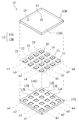
- the pump unit 10 includes a plate-shaped housing 13 having an inlet 11 and an outlet 12, a micropump 15 (see FIG. 3) housed in the housing 13, and a light emitting diode 18. And using a micropump 15 (see FIG. 3), the fluid is sucked from the inlet 11 and the sucked fluid flows out from the outlet 12.
- the housing 13 has an entrance side accommodation plate 13A and an exit side accommodation plate 13B.
- a concave portion 13K for attaching the micropump 15 is formed on the surface 13AS of the inlet side accommodation plate 13A.
- the recesses 13K are arranged in a lattice pattern.
- a recess for attaching the micropump 15 is also formed on the surface 13BS of the outlet side accommodation plate 13B.
- the concave portion provided on the surface 13BS is provided at a position facing the concave portion 13K when the receiving plates 13A and 13B are overlapped so that the surfaces 13AS and 13BS are aligned with each other.
- a storage space for the micropump 15 is formed by the recess 13K of the inlet side storage plate 13A and the recess of the outlet side storage plate 13B. Accordingly, by placing the micropump 15 in the recess provided in one of the accommodation plates 13A and 13B, the micropump 15 has a grid shape of m rows ⁇ n columns (for example, 4 rows ⁇ 4). Column). Then, the micro pumps 15 are built in the housing 13 in a state of being arranged in a lattice by overlapping the receiving plates 13A and 13B so that the surfaces 13AS and 13BS are aligned with each other.
- the plurality of micropumps 15 (pump group) built in the housing 13 are the most popular group 21 composed of the micropumps 15 arranged in the most popular (m1 row in the figure) and the most downstream row (m4 in the figure). Micro pumps arranged in the row direction (m2 row, m3 row in the figure) between the most downstream row group 24 composed of the micropumps 15 arranged in the row) and the most popular group 21 and the most downstream row group 24. Intermediate row groups 22 and 23 are formed.
- a fluid flow path is formed in the housing 13.
- the flow path is formed so that the suction port and the discharge port of the micropump 15 built in the housing 13 are connected and the fluid is conveyed from the inlet 11 to the outlet 12 in the housing 13. The flow path will be described later.
- the micropump 15 for example, the one proposed in Patent Document WO2008 / 069266 can be used. As shown in FIGS. 4 and 5, the micropump 15 includes a case 31 having a suction port 31A and a discharge port 31B, and a pump device that is built in the case 31 and conveys gas from the suction port 31A to the discharge port 31B. 32 and a power supply terminal 33 exposed to the outside of the case 31.
- the pump device 32 includes a piezoelectric element 32A that is electrically connected to the power supply terminal 33 and can be deformed by applying a voltage, and a deformation box 32B that can be deformed by the operation of the piezoelectric element.
- the deformation box 32B has a diaphragm 32BA and a vibrating wall 32BB.
- Diaphragm 32BA is provided in the portion of deformation box 32B that faces suction port 31A.
- the vibration wall 32BB is provided in a portion of the deformation box 32B that faces the discharge port 31B.
- a primary blower chamber 32K is formed between the diaphragm 32BA and the vibration wall 32BB.
- a piezoelectric element 32A is attached to the surface of the diaphragm 32BA facing the suction port 31A. Furthermore, an opening 32BD for moving the fluid inside and outside the primary blower chamber 32K is formed in the vibration wall 32BB at a position facing the discharge port 31B.
- the vibration wall 32BB resonates due to the movement of the fluid.
- the fluid is sucked from the suction port 31A by the vibration of the diaphragm 32BA and the vibration wall 32BB.
- the fluid sucked from the suction port 31A passes through the secondary blower chamber 32L and is discharged from the discharge port 31B.
- the micropump 15 is suitable for a blower application for transferring a fluid and can be transferred without using a check valve.
- the vibration frequency of the diaphragm 32BA is, for example, 1 kHz or more and preferably 18 kHz or more and 27 kHz or less. Moreover, it is preferable that the frequency of diaphragm 32BA is a non-audible area
- the micropump 15 includes a sensor unit 36 for detecting a failure of the pump device 32.
- the sensor unit 36 includes a pressure sensor that detects the static pressure P of the fluid at the discharge port 31B, and a flow rate sensor that detects the flow rate Q of the fluid at the discharge port 31B.
- the micropump 15 is formed in a plate shape and is extremely small (for example, about 20 mm long ⁇ 20 mm wide ⁇ about 2 mm thick). However, when the input sine wave is 15 Vpp (Volt peak to peak) and 26 kHz, the maximum is about 1 L / Minute fluid can be conveyed, and a maximum static pressure of 2 kPa can be obtained (see FIG. 6).
- the micropump 15 conveys the fluid by the vibration of the diaphragm 32BA by the piezoelectric element 32A, there is a limit to the volume of the fluid that can be conveyed, and the static pressure / flow rate characteristics tend to be as shown in FIG. Proportional multiplier is a negative linear function or similar).
- the flow rate Q is 0.5 L / min.
- the input sine wave is 10 Vpp and 20 Vpp, the amplitude of the piezoelectric element 32A changes, so that the flow rate Q and static pressure P corresponding to the input sine wave can be obtained. That is, when the input sine wave Vpp is smoothly changed, the flow rate Q and the static pressure P can be changed smoothly.
- the flow rate Q and the static pressure P can be changed by changing the frequency of the input sine wave. That is, when the frequency of the input sine wave is changed smoothly, the flow rate Q and the static pressure P can be changed smoothly.
- the flow rate Q and the static pressure P have upper limits depending on the capacity of the piezoelectric element 32A and the strength and durability of the components of the micropump 15. Usually used at rated Vpp and frequency.
- the micropump 15 may have a monomorph (unimofull) structure in which one piezoelectric element 32A is bonded to the diaphragm 32BA as described above, or the two piezoelectric elements 32A are bonded to each other to increase the vibration amount. It may have a bimofull structure.
- the structure of the micropump 15 may be an optimum one according to the purpose such as fluid conveyance. Note that the micropump 15 can convey gas without using a check valve, but instead of the micropump 15, a micropump provided with a check valve at the suction port or the discharge port may be applied.
- the housing 13 includes an external power supply terminal 37, a controller 38, and a wiring 39.
- the external power supply terminal 37 is provided so as to be exposed to the housing 13.
- the controller 38 and the wiring 39 are provided on the inlet side accommodation plate 13A.
- the wiring 39 electrically connects the external power supply terminal 37 and the controller 38.
- the bus 85H electrically connects the controller 38, the light-emitting diode 18, and the power supply terminal 33 provided in each micropump 15. Details of the controller 38 will be described later.
- the housing 13 has an inlet direct coupling mechanism, an outlet direct coupling mechanism, and a flow path forming mechanism that connects the inlet direct coupling mechanism and the outlet direct coupling mechanism.
- the inlet direct connection mechanism includes an inlet direct connection flow path 41 that directly connects the suction ports 31A of all the micropumps 15 belonging to the most popular group 21 (m1 row in the figure) and the inlets 11. is there.
- the inlet direct connection channel 41 is formed in the inlet side accommodation plate 13A.
- a switching valve 41Z is provided in the inlet direct connection flow path 41. The switching valve 41Z is in a parallel state in which the suction ports 31A and the inlets 11 of the plurality of micropumps 15 belonging to the most popular group 21 (m1 row in the figure) communicate with each other and the most popular group 21 (m1 row in the figure).
- any one of the micropumps 15 to which the micropump 15 belongs can be switched between a series state in which the suction port 31A and the inlet 11 communicate with each other.
- the suction ports 31A of all the micropumps 15 belonging to the most popular group 21 may be in communication with the inlet 11 or the most popular group 21 Among the micropumps 15 belonging to (line m1 in the figure), the suction ports 31A of some of the micropumps 15 communicate with the inlet 11 while the remaining suction ports 31A of the micropumps 15 do not communicate with the inlet 11 But you can.
- the outlet direct connection mechanism is an outlet direct connection flow path 42 that directly connects the discharge port 31B and the outlet 12 of the most downstream row group 24 (m4 row in the figure).
- the outlet direct connection flow path 42 is formed in the outlet side accommodation plate 13B.
- the flow path forming mechanism is formed on the inlet side accommodating plate 13A and the outlet side accommodating plate 13B.
- the flow path forming mechanism includes the switching valve 41 ⁇ / b> Z, the intermediate flow path 43, and the opening / closing mechanism provided in the intermediate flow path 43.
- the intermediate flow path 43 includes the most upstream discharge flow path 51B, the intermediate suction flow path 52A, the intermediate discharge flow path 52B, the intermediate suction flow path 53A, the intermediate discharge flow path 53B, and the most downstream suction. It has a mouth channel 54A, serial channels 61 to 63, and row bypass channels 71 to 73.
- the most upstream discharge port channel 51B connects the discharge ports 31B of all the micropumps 15 belonging to the most popular group 21 (m1 row in the figure).
- the intermediate suction port flow path 52A connects the suction ports 31A of all the micropumps 15 belonging to the intermediate row group 22 (m2 row in the figure), and the intermediate discharge port flow path 52B is connected to the intermediate row group 22 (in the figure).
- the discharge ports 31B of all the micropumps 15 belonging to (m2 line) are connected.
- the intermediate suction port channel 53A connects the suction ports 31A of all the micropumps 15 belonging to the intermediate row group 23 (m3 row in the figure), and the intermediate discharge port channel 53B is connected to the intermediate row group 23 ( The discharge ports 31B of all the micropumps 15 belonging to (m3 line in the figure) are connected.
- the most downstream suction passage 54A connects the suction ports 31A of all the micropumps 15 belonging to the most downstream row group 24 (m4 row in the figure).
- Each of the inlet channels 52A to 54A is connected to the inlet 11 via the switching valve 41Z and the inlet direct passage 41, and each of the outlet channels 51B to 53B is connected to the outlet 12 via the outlet direct passage 42. Connect with.
- the inlet channels 52A to 54A and the inlet 11 may communicate with each other regardless of the state of the switching valve 41Z. When the switching valve 41Z is in a parallel state, the communication switching valve 41Z is in a series state. If it is, it may be blocked.
- the inlet channel 52A is connected to the inlet direct channel 41 at the position P 52A (see FIG. 9), and the inlet channel 53A is connected at the position P 53A (see FIG. 9).
- the inlet channel 54A is connected to the channel 53A at a position P 53A .
- the discharge port channel 53B communicates with the outlet direct connection channel 42 at the position P 53B (see FIG. 9) and the discharge port channel 52B at the position P 52B (see FIG. 9).
- Discharge port channel 51B communicates with channel 52B at position P 52B (see FIG. 9).
- the serial flow path 61 connects the discharge port flow path 51B and the suction flow path 52A.
- the series channel 62 connects the discharge port channel 52B and the suction port channel 53A, and the series channel 63 connects the discharge port channel 53B and the suction port channel 54A.
- a valve 51Y is provided at a connection position between the discharge port channel 51B and the series channel 61.
- the valve 51Y has a parallel state in which the series flow path 61 is closed while opening the discharge flow path 51B on the downstream side (outlet 12 side) from the valve 51Y, and the discharge flow path on the downstream side (outlet 12 side) from the valve 51Y. Transition between a series state in which the series flow path 61 is opened while closing 51B is possible. In either the parallel state or the serial state, the discharge port channel 51B on the upstream side (discharge port 31B side) with respect to the valve 51Y remains open.
- a valve 52Y is provided at a connection position between the discharge port flow path 52B and the flow path 62
- a valve 53Y is provided at a connection position between the discharge port flow path 53B and the series flow path 63.
- the valve 52Y has a parallel state in which the discharge passage 52B on the downstream side (outlet 12 side) of the valve 52Y is opened and the series passage 62 is closed, and the discharge passage on the downstream side (outlet 12 side) of the valve 52Y. Transition is possible between a series state in which the series flow path 62 is opened while closing 52B. Note that, in either the parallel state or the serial state, the discharge port passage 52B on the upstream side (discharge port 31B side) of the valve 52Y remains open.
- valve 53Y has a parallel state in which the discharge passage 53B on the downstream side (outlet 12 side) of the valve 53Y is opened and the series passage 63 is closed, and the discharge on the downstream side (outlet 12 side) of the valve 53Y. It is possible to change between a series state in which the outlet channel 53B is closed and the series channel 63 is opened. Note that, in either the parallel state or the serial state, the discharge port channel 53B on the upstream side (discharge port 31B side) of the valve 53Y remains open.
- a valve 52X is provided at a connection position between the suction passage 52A and the series passage 61.
- the valve 52X has a parallel state in which another flow path is opened while closing the series flow path 61, and a serial state in which another flow path is opened while closing the suction flow path 52A on the upstream side (inlet 11 side) from the valve 52X.
- a valve 53X is provided at a connection position between the suction channel 53A and the series channel 62
- a valve 54X is provided at a connection position between the suction channel 54A and the series channel 63.
- the valve 53X has a parallel state in which another flow path is opened while closing the serial flow path 62, and a serial state in which another flow path is opened while closing the suction flow path 53A on the upstream side (inlet 11 side) from the valve 53X. In addition, it is possible to transition between a bypass state in which the inlet channel 53A on the downstream side of the valve 53X is closed and another channel is opened.
- the valve 54X has a parallel state in which another flow path is opened while closing the serial flow path 63, and a serial state in which another flow path is opened while closing the suction flow path 54A on the upstream side (inlet 11 side) from the valve 54X. In addition, it is possible to transition between a bypass state in which the inlet channel 54A on the downstream side of the valve 54X is closed and another channel is opened.
- the valve 81 is provided in the inlet direct connection channel 41 on the downstream side of the position P 52A .
- the valve 82 is provided in the inlet channel 52A downstream of the valve 52X, and the valve 83 is provided in the inlet channel 53A downstream of the valve 53X.
- the row bypass channel 71 connects the inlet channel 52A between the valve 82 and the valve 52X and the valve 81.
- the column bypass channel 72 connects the inlet channel 53A between the valve 83 and the valve 53X and the valve 82, and the column bypass channel 73 is the inlet channel between the micropump 15 and the valve 54X. 54A and valve 83 are connected.
- the valve 81 is in a normal state in which the other bypass channel is opened while closing the row bypass channel 71, in a bypass state in which the other channel is opened while closing the inlet direct connection channel 41 on the downstream side of the valve 81, and from the valve 81 In addition, it is possible to change between a closed state in which the upstream inlet direct connection channel 41 is closed and another channel is opened.
- the valve 82 includes a normal state in which the other bypass channel 72 is opened while closing the column bypass channel 72, a bypass state in which the other inlet channel 52A is closed downstream of the valve 82 and another channel is opened, and In addition, it is possible to transition between a closed state in which the other inlet passage is opened while closing the upstream inlet passage 52A.
- the valve 83 has a normal state in which the other bypass channel is opened while closing the row bypass channel 73, a bypass state in which the other channel is opened while closing the inlet channel 53A on the downstream side of the valve 83, and from the valve 83. In addition, it is possible to change between a closed state in which the other inlet passage is opened while closing the upstream inlet passage 53A.
- the opening / closing mechanism includes valves 52X to 54X, 51Y to 53Y, and 81 to 83.
- the first flow path forming part is configured by the suction flow paths 52A to 54A and the valves 52X to 54X
- the second flow path forming part is configured by the series flow paths 61 to 63 and the valves 51Y to 53Y.
- the three flow path forming part is constituted by the discharge port flow paths 51B to 53B and the valves 51Y to 53Y.
- the row bypass flow path is constituted by the suction port flow paths 52A to 54A.
- a sensor unit 45 is provided in the vicinity of the outlet 12 in the outlet direct connection flow path 42.
- the sensor unit 45 includes a pressure sensor 45P that detects the static pressure P of the fluid in the vicinity of the outlet 12 in the outlet direct connection flow path 42, and a flow sensor 45Q that detects the flow rate Q of the fluid in the vicinity of the outlet 12 in the direct outlet flow path 42. And have.
- the controller 38 includes a CPU 85A, a first storage medium 85B, a second storage medium 85C, a third storage medium 85D, an input device 85E, a display device 85F, an input / output interface 85G, and a bus 85H as hardware configurations (see FIG. 10).
- the CPU 85A is a so-called central processing unit, and implements various functions of the controller 38 by executing various programs.
- the first storage medium 85B is a so-called RAM (Random Access Memory) and is a memory used as a work area for the CPU 85A.
- the second storage medium 85C is a so-called ROM (read only memory), and is a memory for storing a basic OS executed by the CPU 85A.
- the third storage medium 85D includes a hard disk device with a built-in magnetic disk, a disk device that houses a CD, DVD, or BD, a non-volatile semiconductor flash memory device, and the like.
- the input device 85E is an input key, a keyboard, and a mouse, and is a device for inputting various information.
- the display device 85F is a display and displays various operation states.
- the input / output interface 85G is connected to the valves 52X to 54X, 51Y to 53Y, 81 to 83, the switching valve 41Z, each micropump 15 (see FIG. 8), and each sensor unit 36, 45 (see FIGS. 5 and 9).
- the input / output interface 85G can acquire data such as a program from an external personal computer and can output measurement results to the personal computer.
- the bus 85H is a wiring for integrally connecting the CPU 85A, the first storage medium 85B, the second storage medium 85C, the third storage medium 85D, the input device 85E, the display device 85F, the input / output interface 85G, and the like. It is.
- the wiring 85H is preferably formed so as to be exposed in the recess 13K (see FIG. 3) provided in the inlet side accommodation plate 13A (see FIG. 9). Accordingly, when the micropump 11 is accommodated in the recess 13K, the external power supply terminal 37 of the micropump 11 accommodated in the recess 13K is electrically connected to the wiring 85. Thus, the wiring to the micropump 11 can be performed by accommodating the micropump 11 in the recess 13K.
- the wiring 85H should just be formed so that it may be exposed to at least any one recessed part among the entrance side accommodation board 13A and the exit side accommodation board 13B.
- (Plate spring, coil spring, etc.) 85J may be provided so as to be exposed.
- the urging member has conductivity, the urging member and the wiring 85H may be electrically connected.
- the controller 38 When the control program stored in the controller 38 is executed by the CPU 85A, the controller 38, as shown in FIG. 11, the pump power supply control unit 94, the failure detection unit 95, the pump substitution control unit 96, and the flow path formation. It functions as a control unit 97 and a warning notification unit 98.
- the pump power supply control unit 94 supplies power to the pump device 32 of the predetermined micropump 15 in accordance with operation conditions set in advance by operating the input device 85E.
- the operating condition refers to, for example, a condition in which a fluid having a desired static pressure P and a desired flow rate Q is discharged from the outlet 12 (see FIG. 5) of the pump unit 10.
- the failure detection unit 95 reads the sensing signal from each sensor of the sensor unit 36 provided in the micropump 15 and determines whether or not the measured value indicated by the sensing signal exceeds the allowable range.
- the allowable range is a value between the upper limit value and the lower limit value set by operating the input device 85E.
- the upper limit value and the lower limit value are set such that the static pressure P and the flow rate Q of the fluid discharged from the micropump 15 that cannot exhibit the intended performance such as deterioration or failure of the pump device 32 are out of the allowable range. .
- the failure detection unit 95 determines that the micropump 15 in which the measurement value is measured is in a normal state, and the measurement value from each sensor When at least one of them exceeds the allowable range, the micropump 15 in which the measured value is measured is determined as a failure state. Further, the failure detection unit 95 outputs a failure signal.
- the failure signal includes information on the identifier of the micropump 15 determined to be a failure (for example, the micropump arranged in the i-th row ⁇ j-th row).
- the pump substitution control unit 96 determines whether or not a failure signal is output from the failure detection unit 95.
- the pump substitution control unit 96 can receive a failure signal.
- the pump substitution control unit 96 can read the power supply list information of the micropump 15 supplied with power by the pump power supply control unit 94 from the pump power supply control unit 94. Further, the pump substitution control unit 96 determines the presence or absence of the micropump 15 of the standby micropump 15.
- the standby state is a state that is not determined to be a failure (normal state), and is a state where power supply is stopped (power supply stop state).
- the flow path formation control unit 97 refers to the sensing signals from the sensor units 36 and 46, and The valves 52X to 54X, 51Y to 53Y, and 81 to 83, which are opening and closing mechanisms, are opened and closed so that the flow rate Q and the static pressure P at the outlet 12 become predetermined values or approach each other.
- the warning notification unit 98 controls the light emitting diode 18 to be turned on and off. Note that the warning device is not limited to the light emitting diode 18, and a buzzer or the like may be used.
- the switching valve 41Z When the switching valve 41Z is set in a parallel state, the valves 81 to 83 are set in a normal state, and the valves 52X to 54X and 51Y to 53Y are set in a parallel state by the flow path formation control unit 97, the inlet 11 enters.
- the fluid is branched for each suction port of the micropump 15 and enters the micropump 15.
- the fluids exiting from the discharge port of the micropump 15 merge again and exit from the outlet 12 (see FIG. 13).
- the pump unit 10 enters a state where the flow rate Q of the fluid exiting from the outlet 12 increases in preference to the static pressure P (flow rate priority transport state).
- the switching valve 41Z is set in a parallel state
- the valves 81 to 83 are set in a normal state
- the valves 52X to 54X and 51Y to 52Y are in a serial state
- the valve 53Y is in a parallel state by the flow path formation control unit 97.
- the flow rate Q and static pressure P of the fluid exiting the outlet 12 take values between the previous two examples.
- the pump device 32 if the pump device 32 is in a state in which the pump device 32 does not operate normally (hereinafter referred to as a failure state), the flow rate Q of the fluid that exits from the outlet 12 And the static pressure P cannot be controlled with high accuracy.
- micropumps 15 are arranged in a grid (4 rows ⁇ 4 columns), all the micropumps 15 located in the fourth column and the fourth row are used as spare micropumps. 15 is assumed.
- the pump power supply control unit 94 supplies power only to the micropumps 15 in the first to third rows and the first to third columns.
- the micropumps 15 in the 1st to 3rd rows ⁇ 1st to 3rd columns are in an operating state, and the spare micropump 15 is in a power supply stopped state.
- the flow path formation control unit 97 sets the switching valve 41Z in a parallel state, the first to third rows of valves 81 to 83 in a normal state, the fourth row of valves 81 to 83 in a blocked state, and the first to third rows.
- the valves 51Y to 52Y are set in series, the first to third rows of valves 53Y are set in parallel, and the first to third rows of valves 52X to 54X are set in series.
- first to third row valves 54X, the fourth row valves 52X to 54X, and the valves 51Y to 53Y may be set in series. Thereby, the pump unit 10 is in a state in which the static pressure P of the fluid exiting from the outlet 12 increases in preference to the flow rate Q.
- the failure detection unit 95 reads a sensing signal from each sensor unit 36.
- the reading timing of the sensing signal may be every fixed period or may be continuous.
- the failure detection unit 95 determines whether or not the measurement value indicated by the read sensing signal is out of the allowable range. When each measured value is within the allowable range, the failure detection unit 95 determines that the micropump 15 that has read the sensing signal is in a normal state. On the other hand, when each measured value is out of the allowable range, the failure detection unit 95 determines that the micropump 15 that has read the sensing signal is in a failure state. If it is determined that there is a faulty micro pump 15, the failure detection unit 95 outputs a failure signal.
- the pump substitution control unit 96 determines whether or not a failure signal is output from the failure detection unit 95. When the pump substitution control unit 96 determines that “a failure signal is output from the failure detection unit 95”, “whether there is a standby micropump 15 among the micropumps 15 built in the pump unit 10”. judge. When the pump substitution control unit 96 determines that there is a standby micropump 15, the pump power supply control unit 94 selects the micropump 15 selected from the standby micropumps 15 (hereinafter, the selected micropump 15). The power supply is started. In addition, it is preferable that the pump electric power feeding control part 94 stops the electric power feeding of the micropump 15 determined to be in a failure state.
- the flow path formation control unit 97 opens and closes the valves 51Y to 53Y, 52X to 54X, and 81 to 83 so that the fluid flows to the selected micropump 15 instead of the micropump 15 determined to be faulty. I do. Thereby, even if the micro pump 15 in a fault state exists in the pump unit 10, a fluid having a desired static pressure P and a desired flow rate Q can be discharged from the outlet 12 of the pump unit 10.
- the flow path formation control unit 97 selects an arbitrary micropump 15 from the standby micropumps 15 in the standby state.
- the flow path formation control unit 97 bypasses the valve 52X in the third row and the valve 53X in the fourth row.
- the fourth row valve 52X and the third row valve 53X are set in a parallel state
- the fourth row valve 52Y is set in a series state
- the fourth row valve 82 is set in a normal state.
- the fluid that has passed through the micropump 15 in the first row ⁇ third column passes through the micropump 15 in the second row ⁇ fourth column instead of the micropump 15 in the second row ⁇ third column. It passes through the micropump 15 in the third row ⁇ third column (see FIG. 15). For this reason, a fluid having an intended flow rate Q and an intended static pressure P can be discharged from the outlet 12.
- the flow path formation control unit 97 puts the valve 82 in the third row into the bypass state and sets the valve in the third row 83 is set to the normal state, and the valves 53Y and 54X in the third row are set in series.
- the third row of valves 53X is preferably in series.
- the warning notification unit 98 notifies the abnormal state of the pump unit 10 by controlling the light emitting diode 18 to be turned on and off. be able to. Thereby, use of the pump unit 10 which cannot output the fluid of the desired static pressure P and the desired flow volume Q can be avoided.
- the micropumps 15 are arranged in a lattice pattern, and the flow path forming mechanism, that is, the intermediate flow path 43 and the opening / closing mechanism (each valve) provided in the intermediate flow path 43, It becomes possible to control the series connection and the parallel connection of each micropump 15 in a rational combination. As a result, even if the micropump 15 is used alone, the flow rate and the static pressure are insufficient, a plurality of micropumps 15 can be used in combination, so that it can be used in the same manner as a conventional blower or syringe pump.
- the micropump 15 since the micropump 15 has a small size, even if a plurality of the micropumps 15 are arranged, the micropump 15 can be configured to be smaller and lighter than conventional blowers.
- the control configuration is also extremely high. Can be concise.
- a conventional blower or syringe pump if one of them fails, the entire fluid transport will be delayed, but according to the pump unit 10 described above, even if each micropump 15 fails, Since it can be supplemented by another micropump 15, reliability and safety can be improved.
- the number of micropumps 15 in the downstream line is equal or smaller than the number of micropumps 15 belonging to the epidemic.
- useless operation of the micropump 15 is suppressed, so that power consumption can be reduced, which is particularly suitable for battery-driven applications, for example.
- connection relation is collectively switched for the whole of the plurality of micropumps 15 arranged in each row.
- the configuration of the valve is simplified and the maintainability is improved.
- the inlet 11 of the pump unit 10 may be one or plural.
- the plurality of inlets 11 may be connected to the inlet direct connection channel 41 or may be directly connected to the micropump 15 belonging to the most popular group 21.
- the number of intermediate row groups may be one, or three or more.
- the most popular group 21, the middle row groups 22, 23, and the most downstream row group 24 are arranged in this order in the housing 13, but the present invention is not limited to this.
- the order of the most downstream row group 24, the middle row groups 22, 23, the order of the most downstream row group 24, the middle row groups 22, 23, the most popular group 21, and the like may be used.
- the micropumps 15 are arranged in a grid pattern in the housing 13, but the present invention is not limited to this, and the micropumps 15 may be arranged in one row or one column.
- the micropump 15 is fitted to the housing 13, but the present invention is not limited to this, and the micropump 15 and the housing 13 may be integrally formed.
- the micropumps 15 are arranged in a grid pattern on a plane, but the present invention is not limited to this, and a plurality of micropumps 15 may be arranged to overlap each other.
- the micropump 15 may be stacked so that the inlet 11 of the second micropump 15 is positioned above the outlet 12 of the first micropump 15 (see FIGS. 17 to 20).
- the 17 to 18 includes a casing 13 having an inlet 11 and an outlet 12 and a pump unit 15 accommodated in the casing 13.
- the housing 13 having the pump unit housing hole 13X for housing the pump unit 15 includes a first housing forming block 13L and a second housing forming block 13R. Each of the first housing forming block 13L and the second housing forming block 13R is formed with a predetermined recess.
- the pump unit accommodation hole 13X is formed by combining the first housing forming block 13L and the second housing forming block 13R so that the recesses face each other.
- the micropumps 15A, 15B, and 15C arranged in this order from the inlet 11 to the outlet 12 in the housing 13, and the micropump 15A and the micropump 15B are arranged.
- a flow path block 13SA disposed between the two and a flow path block 13SB disposed between the micro pump 15B and the micro pump 15C.
- the housing 13 is formed with an inlet direct flow path 41 that connects the suction port 31A and the inlet 11 of the micropump 15A, and an outlet direct flow path 42 that connects the discharge port 31B and the outlet 12 of the micropump 15C.
- the direct inlet passage 41 includes a direct passage 41A that directly connects the suction port 31A and the inlet 11 of the micropump 15A, and a branch passage 41B that branches from the direct passage 41A.
- the branch path 41B extends to the vicinity of the suction port 31A of the micropump 15C so as to extend along the micropumps 15A, 15B, and 15C.
- the outlet direct connection flow path 42 includes a direct connection path 42A that directly connects the discharge port 31B and the outlet 12 of the micro pump 15C, and a branch path 42B that branches from the direct connection path 42A.
- the branch path 42B extends to the vicinity of the discharge port 31B of the micropump 15A along the micropumps 15C, 15B, 15A.
- the flow path block 13SA is formed in a rectangular parallelepiped shape.
- the flow path block 13SA includes a series flow path 90A that directly connects the discharge port 31B of the micropump 15A and the suction port 31A of the micropump 15B, a series valve 90AB that opens and closes the series flow path 90A, and a discharge port more than the series valve 90AB.
- a suction side parallel flow path 91A that directly connects the passage 90A and the branch path 41B and a suction side parallel valve 91AB that opens and closes the suction side parallel flow path 91A are formed.
- illustration of each valve 90AB, 91AB, and 92AB in FIG. 20 is abbreviate
- the flow path block 13SB is the same as the flow path block 13SA, that is, formed in a rectangular parallelepiped shape, and a series flow path 90B that directly connects the discharge port 31B of the micropump 15B and the suction port 31A of the micropump 15C.
- a series valve 90BB that opens and closes the passage 90B, a discharge side parallel passage 92B that directly connects the series passage 90B and the branch passage 42B closer to the discharge port 31B than the series valve 90BB, and a discharge side that opens and closes the discharge side parallel passage 92B
- a parallel valve 92BB a suction side parallel flow path 91B that directly connects the serial flow path 90B and the branch path 41B closer to the suction port 31A than the series valve 90BB, a suction side parallel valve 91BB that opens and closes the suction side parallel flow path 91B, Is formed.
- the serial flow path 90A penetrates from the discharge port side surface 13AL of the flow path block 13SA facing the discharge port 31B of the micropump 15A to the suction port side surface 13AU of the flow path block 13SA facing the suction port 31A of the micropump 15B. It is formed.
- the discharge side parallel flow path 92A is formed by the groove 13LM formed in the discharge port side surface 13AL and the micro pump 15A.
- the suction side parallel flow path 91A is formed by the groove 13UM formed in the suction port side surface 13AU and the micro pump 15A.
- the serial flow path 90B penetrates from the discharge port side surface 13BL of the flow path block 13SB facing the discharge port 31B of the micropump 15B to the suction port side surface 13BU of the flow path block 13SB facing the suction port 31A of the micropump 15C. To be formed.
- the discharge side parallel flow path 92B is formed by the groove formed on the discharge port side surface 13BL and the micro pump 15A.
- the housing of the micropump 15 ⁇ / b> C and the suction port side surface 13 ⁇ / b> BU are in contact with each other, so that a suction side parallel flow path 91 ⁇ / b> B is formed by the groove formed in the suction port side surface 13 ⁇ / b> BU and the micropump 15 ⁇ / b> C.
- the switching valve 41Z, the series valves 90AB and 90BB, the suction side parallel valves 91AB and 91BB, and the discharge side parallel valves 92AB and 92BB are opened and closed by the controller 38 (see FIG. 7).
- the switching valve 41Z is set in a parallel state, the series valves 90AB and 90BB are closed, and the suction side parallel valves 91AB and 91BB and the discharge side parallel valves 92AB and 92BB are opened (see FIG. 19).
- the fluid entering from the inlet 11 is distributed via the inlet direct connection channel 41, the suction side parallel channel 91A, and the suction side parallel channel 91B, and the distributed fluid is the suction ports 31A of the micropumps 15A to 15C, respectively. Inhaled.
- the pump device 32 In each of the micro pumps 15A to 15C, the pump device 32 (see FIG. 5) compresses the fluid sucked from the suction port 31A.
- the fluid compressed by the micropumps 15A to 15C exits from the discharge port 31B, joins via the discharge side parallel flow path 92A, the discharge side parallel flow path 92B, and the outlet direct connection flow path 42, and then the outlet 12 Get out of.
- the switching valve 41Z is set in a series state, the series valves 90AB and 90BB are set in an open state, and the suction side parallel valves 91AB and 91BB and the discharge side parallel valves 92AB and 92BB are set in a closed state (see FIG. 18).
- the fluid that has entered from the inlet 11 is sucked into the suction port 31A of the micropump 15A through the inlet direct connection channel 41.
- the pump device 32 (see FIG. 5) compresses the fluid sucked from the suction port 31A.
- the fluid compressed by the micropump 15A exits from the discharge port 31B and is sucked into the suction port 31A of the micropump 15B through the serial flow path 90A.
- the fluid sucked from the suction port 31A of the micropump 15B is compressed by the pump device 32 (see FIG. 5), and then sucked into the suction port 31A of the micropump 15C via the discharge port 31B and the serial channel 90B. .
- the fluid sucked from the suction port 31A of the micropump 15C is compressed by the pump device 32 (see FIG. 5), and then exits from the outlet 12 via the discharge port 31B and the outlet direct connection channel.
- the static pressure P and the flow rate Q of the fluid flowing out from the outlet 12 are opened and closed by the switching valve 41Z, the series valves 90AB and 90BB, the suction side parallel valves 91AB and 91BB, and the discharge side parallel valves 92AB and 92BB. Can be adjusted as appropriate.
- the discharge side parallel flow path 92A is formed by the groove 13LM and the micropump 15A formed in the discharge port side surface 13AL, it is possible to reduce the trouble of forming the discharge side parallel flow path 92A.
- the suction side parallel flow path 91A is formed by the groove 13UM and the micropump 15A formed in the suction side surface 13AU, the labor for forming the suction side parallel flow path 91A can be reduced.
- each of the flow path forming plates 13AA to 13AD has a through hole formed in a thickness direction at a predetermined position. Further, each of the flow path forming plates 13AA to 13AD has a groove at a predetermined position on the surface facing the other flow path forming plate.
- the outlet side accommodation plate 13B is preferably formed by the flow path forming plates 13BA to 13BB.
- Each of the flow path forming plates 13BA to 13BB has a through hole formed in the thickness direction and a groove formed on a surface facing the other flow path forming plate at predetermined positions.
- the respective flow paths 42, 51B to 53B and downstream of 61 to 63 of the respective flow paths are formed by through holes and grooves formed in the flow path forming plates 13BA to 13BB. A part is formed.
- the breathing assistance device 700 includes a flow path 702 through which breathing gas passes, and an expiratory nozzle 704 and an inhalation nozzle that are disposed in the flow path 702 and can release acceleration air in the exhalation direction and the inhalation direction, respectively.
- 706 a pump unit 10 disposed on the outer surface of the flow path 702 along the circumferential direction, and a battery 710 that drives the pump unit 10.
- Venturi walls 720 are disposed in the vicinity of the exhalation and inhalation nozzles 704 and 706 disposed in the flow path 702, respectively.
- the battery 710 can be omitted by disposing the battery 710 at a remote location or connecting a power supply line.
- a breathing switching valve 725 is disposed at the outlet 12 of the pump unit 10 (see FIG. 1; hereinafter also referred to as an integrated discharge port).
- the breath switching valve 725 switches between a case where the air discharged from the integrated discharge port is discharged from the exhalation nozzle 704 and a case where the air is discharged from the intake nozzle 706.
- FIG. 23A when the air is discharged from the exhalation nozzle 704, the exhalation side becomes a negative pressure state by spreading the air by the venturi wall 720, and carbon dioxide discharged from the inhalation side (lung side) is drawn in. And let it flow in the direction of exhalation. As a result, exhalation operation can be assisted.
- FIG. 23A when the air is discharged from the exhalation nozzle 704, the exhalation side becomes a negative pressure state by spreading the air by the venturi wall 720, and carbon dioxide discharged from the inhalation side (lung side) is drawn in. And let it flow in the direction of exhalation. As
- the respiratory assistance device 700 since the miniaturized pump unit 10 is directly fixed to the piping itself constituting the flow path 702, the respiratory assistance device 700 can be configured extremely compactly. Furthermore, since the flow path 702 and the pump unit 10 are integrated, even if the flow path 702 moves in conjunction with the movement of the user's body, the flow path 702 and the pump unit 10 move together. In addition, the connection between the intake nozzles 704 and 706 and the pump unit 10 is not interrupted. Therefore, the stability of the breathing assistance operation is increased and the user can easily move the body.
- the respiratory assistance device 700 can be used continuously with the intubation tube inserted from the user's mouth toward the trachea.
- the nasal mask 830 is used.
- the flow path 702 can be connected to and used.
- a case where one pump unit 10 is switched by the breath switching valve 725 and supplied to the exhalation nozzle or the intake nozzle is illustrated, but two pump units 10 are prepared, and the exhalation nozzle and the inspiration nozzle are respectively provided. You may make it connect with a nozzle.
- pump unit and the respiratory assistance device of the present invention are not limited to the above-described embodiments, and it goes without saying that various changes can be made without departing from the scope of the present invention.
- the pump unit of the present invention can be used for various purposes other than the respiratory assistance device.
- the respiratory assistance apparatus of this invention can be utilized for the purpose of respiratory assistance of various living things.
Landscapes
- Health & Medical Sciences (AREA)
- Engineering & Computer Science (AREA)
- Pulmonology (AREA)
- Life Sciences & Earth Sciences (AREA)
- General Health & Medical Sciences (AREA)
- Biomedical Technology (AREA)
- Heart & Thoracic Surgery (AREA)
- Hematology (AREA)
- Emergency Medicine (AREA)
- Animal Behavior & Ethology (AREA)
- Anesthesiology (AREA)
- Public Health (AREA)
- Veterinary Medicine (AREA)
- Mechanical Engineering (AREA)
- General Engineering & Computer Science (AREA)
- Otolaryngology (AREA)
- Reciprocating Pumps (AREA)
- Compressors, Vaccum Pumps And Other Relevant Systems (AREA)
- Control Of Positive-Displacement Pumps (AREA)
Abstract
A pump unit (10) comprises a casing (13) provided with an inlet (11) and outlet (12) for a fluid, and a pump group comprised of micro pumps (15) aligned inside the casing (13) and used to discharge the fluid entering through the inlet (11) out through the outlet (12). The pump group has a micro pump (15) positioned at the highest flow (m1), a micro pump (15) positioned at the lowest flow (m4), and micro pumps (15) positioned in the middle (m2-m3). The casing (13) has an inlet direct-connecting pipe (41) for directly connecting the inlet (11) and an intake port (31A) of the micro pump (15) positioned at the highest flow, an outlet direct-connecting pipe (42) for directly connecting the outlet (12) and a discharge port (31B) of the micro pump (15) positioned at the lowest flow, and a pipe-forming mechanism capable of switching between a state in which the micro pumps (15) are connected in series and a state in which the micro pumps (15) are connected in parallel.
Description
本発明は、マイクロポンプを利用して流体を搬送するポンプユニット、及びこのポンプユニットを用いた呼吸補助装置に関する。
The present invention relates to a pump unit that transports fluid using a micropump, and a respiratory assistance device that uses this pump unit.
医療現場では人工呼吸器など呼吸補助装置が用いられる。この呼吸補助装置の種類には、自発呼吸のない患者(全身麻酔、心肺蘇生中、重篤な患者)に用いる調節換気(Controlled Ventilation)方式や、患者の自発呼吸に合わせて気道に陽圧を作り出す補助換気方式(Assisted Ventilation)方式、補助換気と調節換気を組み合わせた部分的補助換気(Assist/Control)方式、気道の供給する気体を5~40Hzの頻度で振動させて、1~2ml/kgの非常に少ない1回換気量を実現する高頻度振動換気(high frequency occilation)などが採用される。
In the medical field, respiratory assistance devices such as ventilators are used. This type of respiratory assistance device includes a controlled ventilation method used for patients who do not breathe spontaneously (general anesthesia, cardiopulmonary resuscitation, and severe patients), and positive pressure on the airways according to the patient's spontaneous breathing. Assisted Ventilation method to create, Partial Assist / Control method combining auxiliary ventilation and controlled ventilation, gas supplied by the airway is vibrated at a frequency of 5-40 Hz, 1-2 ml / kg High frequency vibration ventilation that achieves extremely low tidal volume is adopted.
なお、この呼吸補助装置は、睡眠時の呼吸障害の患者にも利用される。この呼吸障害は、睡眠中に気道の筋肉が弛緩して舌根部や軟口蓋が下がり、気道を閉塞することによって生じる。この種の呼吸障害の患者に対しても、気道に正圧を印加することで、その症状が緩和する。
Note that this respiratory assistance device is also used for patients with respiratory disorders during sleep. This respiratory disorder occurs when the airway muscles relax during sleep and the tongue base and soft palate fall, closing the airway. Even for patients with this type of respiratory distress, the symptoms are alleviated by applying positive pressure to the airways.
いずれの呼吸補助装置においても、気道に陽圧を作り出すためのポンプユニットが必要となる。このポンプユニットの動力源には、ファンを回転させて気体を搬送するブロアや、ピストンを往復運動させて気体を搬送するシリンダポンプなどが使用される。
In any respiratory assistance device, a pump unit is required to create a positive pressure in the airway. As a power source of the pump unit, a blower that rotates a fan to convey gas, a cylinder pump that reciprocates a piston to convey gas, and the like are used.
しかしながら、従来の呼吸補助装置では、このポンプユニットが比較的大きいことから、これを箱状の筐体に収容して使用者の脇に設置して用いる。従って、呼吸補助装置のコンパクト化が難しいという問題があった。
However, in the conventional breathing assistance apparatus, since this pump unit is relatively large, it is housed in a box-shaped housing and used beside the user. Therefore, there is a problem that it is difficult to make the respiratory assistance device compact.
また、呼吸補助装置で用いるポンプユニットは、例えば図26に示されるように、吸気動作時は、最初は高い流量で素早く昇圧(陽圧化)し、その後、更に圧力を高めて吸気をアシストしながら流量を一定に維持する。呼気動作時は、高い流量で素早く減圧(負圧化)し、圧力が低下したら流量を次第に低下させて肺に負担をかけないように制御する。この制御は一例であり、実際には様々制御モードが要求されるが、この種の細かい制御を行う為には、大きめのブロアやシリンダポンプを利用して、圧力と流量を自在に変更できるようにしなければならない。従って、ポンプユニットの小型化が益々難しいという問題があった。
In addition, as shown in FIG. 26, for example, the pump unit used in the breathing assist device first boosts pressure quickly (positive pressure) at a high flow rate during the intake operation, and then further increases the pressure to assist the intake. While maintaining the flow rate constant. During the exhalation operation, the pressure is quickly reduced (negative pressure) at a high flow rate, and when the pressure drops, the flow rate is gradually reduced so as not to burden the lungs. This control is an example, and various control modes are actually required, but in order to perform this kind of fine control, a large blower or cylinder pump can be used to freely change the pressure and flow rate. Must be. Therefore, there is a problem that it is increasingly difficult to reduce the size of the pump unit.
本発明は上記問題点に鑑みてなされたものであり、圧力や流量を自在に制御可能としながらも、大幅な小型化を実現できるポンプユニット及びこのポンプユニットを用いた呼吸補助装置を提供することを目的とする。
The present invention has been made in view of the above problems, and provides a pump unit and a breathing assistance apparatus using the pump unit that can realize significant downsizing while allowing pressure and flow rate to be freely controlled. With the goal.
本発明者の鋭意研究により、上記目的は以下の手段によって達成される。
The above-mentioned object is achieved by the following means based on the earnest research of the present inventors.
The above-mentioned object is achieved by the following means based on the earnest research of the present inventors.
即ち、上記目的を達成するポンプユニットは、流体の入口及び出口が設けられた本体と、前記本体の内部に並べられ前記入口から入った流体を前記出口から出す複数のマイクロポンプからなるポンプ群とを備え、前記ポンプ群は、直列状態にて最上流に位置するマイクロポンプと、直列状態にて最下流に位置するマイクロポンプと、直列状態にて中間に位置するマイクロポンプとを有し、前記本体は、前記最上流に位置するマイクロポンプの吸入口及び前記入口を直結する入口直結流路と、前記最下流に位置するマイクロポンプの吸出口及び前記出口を直結する出口直結流路と、前記ポンプ群を構成する前記マイクロポンプをつなぐ流路形成機構とを有し、前記流路形成機構は、前記最上流に位置するマイクロポンプ、前記中間に位置するマイクロポンプ、前記最下流に位置するマイクロポンプをこの順につなぐ直列状態と、前記中間または前記最下流に位置する前記マイクロポンプの吸入口と前記入口とをつなぐ分岐路を形成するとともに、前記最上流または前記中間に位置する前記マイクロポンプの吐出口と前記出口とをつなぐ合流路を形成する並列状態との間で切り替え自在であることを特徴とする。
That is, a pump unit that achieves the above object includes a main body provided with an inlet and an outlet for a fluid, and a pump group including a plurality of micropumps arranged inside the main body and discharging the fluid entered from the inlet through the outlet. The pump group includes a micropump located at the most upstream in the series state, a micropump located at the most downstream in the series state, and a micropump located in the middle in the series state, The main body has an inlet directly connected flow path directly connecting the inlet and the inlet of the micropump located at the most upstream, an outlet directly connected flow path connecting the outlet and the outlet of the micro pump located at the most downstream, A flow path forming mechanism that connects the micro pumps constituting the pump group, and the flow path forming mechanism is positioned in the middle of the micro pump located in the uppermost stream. Forming a branch path connecting the inlet and the inlet of the micropump located in the middle or the most downstream, and the uppermost stream or It is possible to switch between a parallel state that forms a combined flow path connecting the discharge port and the outlet of the micro pump located in the middle.
前記流路形成機構を制御する流路形成制御部を有することが好ましい。また、前記流路形成機構は、前記中間及び前記最下流に位置する前記マイクロポンプの吸入口及び前記本体の入口を連通・遮断する第1流路形成手段と、前記最上流、前記中間、前記最下流の順に連結される前記マイクロポンプの間において、上流側の前記マイクロポンプの吐出口及び下流側の前記マイクロポンプの吸入口を連通・遮断する第2流路形成手段と、前記最上流及び前記中間に位置する前記マイクロポンプの吐出口及び前記本体の出口を連通・遮断する第3流路形成手段と、を備えたことが好ましい。
It is preferable to have a flow path formation control unit that controls the flow path formation mechanism. Further, the flow path forming mechanism includes first flow path forming means for communicating / blocking the suction port of the micropump located at the middle and the most downstream side and the inlet of the main body, the most upstream, the middle, A second flow path forming means for communicating / blocking the discharge port of the upstream micro pump and the suction port of the downstream micro pump between the micro pumps connected in the most downstream order; It is preferable that a third flow path forming unit that communicates and blocks the discharge port of the micro pump located in the middle and the outlet of the main body is provided.
前記ポンプ群を構成する前記マイクロポンプは互いに重なるように配されていてもよいし、格子状に配されていてもよい。また、行方向に並ぶ複数の前記マイクロポンプの吸入口同士をつなぐとともに、行方向に並ぶ複数の前記マイクロポンプの吐出口同士をつなぐ行バイパス流路と、前記行バイパス流路の開閉を行う行バイパス流路開閉装置とを備えたことが好ましい。さらに、列方向に並ぶ複数の前記マイクロポンプの吸入口同士をつなぐとともに、列方向に並ぶ複数の前記マイクロポンプの吐出口同士をつなぐ列バイパス流路と、前記列バイパス流路の開閉を行う列バイパス流路開閉装置とを備えたことが好ましい。
The micro pumps constituting the pump group may be arranged so as to overlap each other, or may be arranged in a lattice shape. In addition, a row bypass passage that connects the suction ports of the plurality of micropumps arranged in the row direction, and a row bypass channel that connects the discharge ports of the plurality of micropumps arranged in the row direction, and a row that opens and closes the row bypass channel. It is preferable to include a bypass flow path opening / closing device. Furthermore, a row bypass passage that connects the suction ports of the plurality of micropumps arranged in the column direction and a plurality of the discharge ports of the micropumps arranged in the row direction, and a row that opens and closes the row bypass channel It is preferable to include a bypass flow path opening / closing device.
前記流路形成制御機部は、前記マイクロポンプの故障を検知する故障検知部と、前記故障したマイクロポンプの代わりが有るか否かを判定するポンプ代替制御部と、代わりの前記マイクロポンプが有ると判定された場合には、前記故障信号により特定される前記マイクロポンプへ向かって流れる前記流体を前記代わりのマイクロポンプへ送り、前記代わりのマイクロポンプから出た前記流体を、前記故障信号により特定された前記マイクロポンプの次に流れる前記マイクロポンプへ送るように、前記行バイパス流路開閉装置または前記列バイパス流路開閉装置を制御するバイパス制御部とを有することが好ましい。
The flow path formation controller unit includes a failure detection unit that detects a failure of the micropump, a pump replacement control unit that determines whether or not there is a replacement for the failed micropump, and the replacement micropump. The fluid flowing toward the micro pump specified by the failure signal is sent to the alternative micro pump, and the fluid exiting from the alternative micro pump is specified by the failure signal. It is preferable to have a bypass control unit that controls the row bypass channel switching device or the column bypass channel switching device so as to send the micropump that flows next to the micropump.
警告を報知可能な警告機を備え、前記流路形成制御部は、代わりの前記マイクロポンプが無いと判定された場合には、前記警告機を用いて警告を行う警告報知部を有することが好ましい。
It is preferable that a warning device capable of notifying a warning is provided, and the flow path formation control unit includes a warning notification unit that performs a warning using the warning device when it is determined that there is no alternative micropump. .
前記本体には、前記マイクロポンプを収容するための凹部が形成されたことが好ましい。また、前記マイクロポンプは、自身に内蔵されたポンプデバイスを給電するための給電端子を有し、前記凹部には、前記凹部に収容された前記マイクロポンプの前記給電端子と電気的に接続する配線が設けられたことが好ましい。
It is preferable that a concave portion for accommodating the micropump is formed in the main body. The micropump has a power supply terminal for supplying power to a pump device built in the micropump, and the recess is a wiring electrically connected to the power supply terminal of the micropump housed in the recess. Is preferably provided.
前記本体は、前記入口を有する入口パッケージと、前記出口を有する出口パッケージとを有し、前記入口パッケージには前記第1流路形成部が設けられ、前記出口パッケージには前記第3流路形成部が設けられたことが好ましい。
The main body includes an inlet package having the inlet and an outlet package having the outlet. The inlet package is provided with the first flow path forming portion, and the outlet package has the third flow path formed. It is preferable that a portion is provided.
上記目的を達成する呼吸補助装置は、呼気又は吸気の気体が通過する流路と、前記流路内に配置されて呼気又は吸気方向に加速用の気体を噴出するノズルと、前記流路の周囲に固定され、前記ノズルに対して前記加速用の気体を供給する上記のポンプユニットとを備えたことを特徴とする。
A breathing assistance device that achieves the above object includes a flow path through which exhaled or inhaled gas passes, a nozzle that is arranged in the flow path and ejects an acceleration gas in the direction of exhaled air or inhaled, and the periphery of the flow path And the above pump unit for supplying the gas for acceleration to the nozzle.
A breathing assistance device that achieves the above object includes a flow path through which exhaled or inhaled gas passes, a nozzle that is arranged in the flow path and ejects an acceleration gas in the direction of exhaled air or inhaled, and the periphery of the flow path And the above pump unit for supplying the gas for acceleration to the nozzle.
本発明によれば、圧力や流量を自在に制御可能としながら、ポンプユニットを大幅に小型化することが可能になるという優れた効果を奏し得る。
According to the present invention, it is possible to achieve an excellent effect that the pump unit can be greatly downsized while the pressure and flow rate can be freely controlled.
以下、本発明の実施の形態を、添付図面を参照して説明する。
Hereinafter, embodiments of the present invention will be described with reference to the accompanying drawings.
図1~2に示すように、ポンプユニット10は、入口11及び出口12を有する板状の筐体13と、筐体13内に収容されるマイクロポンプ15(図3参照)と、発光ダイオード18とを備え、マイクロポンプ15(図3参照)を用いて、入口11から流体を吸引し、吸引した流体を出口12から流出するものである。
As shown in FIGS. 1 and 2, the pump unit 10 includes a plate-shaped housing 13 having an inlet 11 and an outlet 12, a micropump 15 (see FIG. 3) housed in the housing 13, and a light emitting diode 18. And using a micropump 15 (see FIG. 3), the fluid is sucked from the inlet 11 and the sucked fluid flows out from the outlet 12.
図3に示すように、筐体13は、入口側収容板13Aと、出口側収容板13Bとを有する。入口側収容板13Aの面13ASには、マイクロポンプ15を取り付けるための凹部13Kが形成される。面13ASにおいて、凹部13Kは、格子状に並べられる。また、図示は省略するが、出口側収容板13Bの面13BSにも、マイクロポンプ15を取り付けるための凹部が形成される。面13BSに設けられた凹部は、面13AS、13BS同士を合わせるように各収容板13A、13Bを重ねたときに、凹部13Kと正対する位置に設けられる。面13AS、13BS同士を合わせるように各収容板13A、13Bを重ねると、入口側収容板13Aの凹部13Kと出口側収容板13Bの凹部とにより、マイクロポンプ15の収容空間が形成される。したがって、収容板13A、13Bのいずれか一方の収容板に設けられた凹部にマイクロポンプ15を載置することにより、マイクロポンプ15は、m行×n列の格子状(例えば、4行×4列)に配される。そして、面13AS、13BS同士を合わせるように各収容板13A、13Bを重ねることにより、マイクロポンプ15は、格子状に並んだ状態で筐体13に内蔵される。
As shown in FIG. 3, the housing 13 has an entrance side accommodation plate 13A and an exit side accommodation plate 13B. A concave portion 13K for attaching the micropump 15 is formed on the surface 13AS of the inlet side accommodation plate 13A. In the surface 13AS, the recesses 13K are arranged in a lattice pattern. Although not shown, a recess for attaching the micropump 15 is also formed on the surface 13BS of the outlet side accommodation plate 13B. The concave portion provided on the surface 13BS is provided at a position facing the concave portion 13K when the receiving plates 13A and 13B are overlapped so that the surfaces 13AS and 13BS are aligned with each other. When the storage plates 13A and 13B are overlapped so that the surfaces 13AS and 13BS are aligned with each other, a storage space for the micropump 15 is formed by the recess 13K of the inlet side storage plate 13A and the recess of the outlet side storage plate 13B. Accordingly, by placing the micropump 15 in the recess provided in one of the accommodation plates 13A and 13B, the micropump 15 has a grid shape of m rows × n columns (for example, 4 rows × 4). Column). Then, the micro pumps 15 are built in the housing 13 in a state of being arranged in a lattice by overlapping the receiving plates 13A and 13B so that the surfaces 13AS and 13BS are aligned with each other.
筐体13に内蔵された複数のマイクロポンプ15(ポンプ群)は、最上流行(図中のm1行)に並べられたマイクロポンプ15によりなる最上流行グループ21と、最下流行(図中のm4行)に並べられたマイクロポンプ15によりなる最下流行グループ24と、最上流行グループ21及び最下流行グループ24の間にて行方向(図中のm2行、m3行)に並べられたマイクロポンプによりなる中間行グループ22、23とを形成する。
The plurality of micropumps 15 (pump group) built in the housing 13 are the most popular group 21 composed of the micropumps 15 arranged in the most popular (m1 row in the figure) and the most downstream row (m4 in the figure). Micro pumps arranged in the row direction (m2 row, m3 row in the figure) between the most downstream row group 24 composed of the micropumps 15 arranged in the row) and the most popular group 21 and the most downstream row group 24. Intermediate row groups 22 and 23 are formed.
筐体13には、流体の流路が形成される。流路は、筐体13に内蔵されたマイクロポンプ15の吸入口及び吐出口をつなぎ、筐体13において入口11から出口12に向けて流体が搬送されるように、形成される。なお、流路については後述する。
A fluid flow path is formed in the housing 13. The flow path is formed so that the suction port and the discharge port of the micropump 15 built in the housing 13 are connected and the fluid is conveyed from the inlet 11 to the outlet 12 in the housing 13. The flow path will be described later.
マイクロポンプ15として、例えば、特許文献WO2008/069266で提案されているものを用いることができる。図4及び図5に示すように、マイクロポンプ15は、吸入口31A及び吐出口31Bが形成されたケース31と、ケース31に内蔵され、吸入口31Aから吐出口31Bまで気体を搬送するポンプデバイス32と、ケース31の外部に露出する給電用端子33とを備える。
As the micropump 15, for example, the one proposed in Patent Document WO2008 / 069266 can be used. As shown in FIGS. 4 and 5, the micropump 15 includes a case 31 having a suction port 31A and a discharge port 31B, and a pump device that is built in the case 31 and conveys gas from the suction port 31A to the discharge port 31B. 32 and a power supply terminal 33 exposed to the outside of the case 31.
図5に示すように、ポンプデバイス32は、給電用端子33と電気的に接続され、電圧の印加により変形可能な圧電素子32Aと、圧電素子の作動によって変形可能な変形箱32Bとを備える。変形箱32Bは、ダイヤフラム32BAと振動壁32BBとを有する。ダイヤフラム32BAは、変形箱32Bのうち吸入口31Aに対向する部分に設けられる。振動壁32BBは、変形箱32Bのうち吐出口31Bに対向する部分に設けられる。ダイヤフラム32BAと振動壁32BBとの間には、一次ブロア室32Kが形成される。ダイヤフラム32BAの吸入口31Aに対向する面には、圧電素子32Aが取り付けられる。さらに、振動壁32BBには、一次ブロア室32Kの内外で流体を移動させるための開口32BDが、吐出口31Bと正対する位置に形成される。
As shown in FIG. 5, the pump device 32 includes a piezoelectric element 32A that is electrically connected to the power supply terminal 33 and can be deformed by applying a voltage, and a deformation box 32B that can be deformed by the operation of the piezoelectric element. The deformation box 32B has a diaphragm 32BA and a vibrating wall 32BB. Diaphragm 32BA is provided in the portion of deformation box 32B that faces suction port 31A. The vibration wall 32BB is provided in a portion of the deformation box 32B that faces the discharge port 31B. A primary blower chamber 32K is formed between the diaphragm 32BA and the vibration wall 32BB. A piezoelectric element 32A is attached to the surface of the diaphragm 32BA facing the suction port 31A. Furthermore, an opening 32BD for moving the fluid inside and outside the primary blower chamber 32K is formed in the vibration wall 32BB at a position facing the discharge port 31B.
圧電素子32Aによってダイヤフラム32BAが振動すると、ケース31及びポンプデバイス32によって形成された二次ブロア室32Lと、一次ブロア室32Kとの間で流体が移動する。流体の移動により、振動壁32BBが共振する。ダイヤフラム32BAと振動壁32BBの振動によって、吸入口31Aから流体が吸い込まれる。吸入口31Aから吸い込まれた流体は、二次ブロア室32Lを通過して、吐出口31Bから放出される。マイクロポンプ15は、流体を搬送するブロア用途に適しており、逆止弁を用いることなく搬送できる。
When the diaphragm 32BA vibrates by the piezoelectric element 32A, the fluid moves between the secondary blower chamber 32L formed by the case 31 and the pump device 32 and the primary blower chamber 32K. The vibration wall 32BB resonates due to the movement of the fluid. The fluid is sucked from the suction port 31A by the vibration of the diaphragm 32BA and the vibration wall 32BB. The fluid sucked from the suction port 31A passes through the secondary blower chamber 32L and is discharged from the discharge port 31B. The micropump 15 is suitable for a blower application for transferring a fluid and can be transferred without using a check valve.
ダイアフラム32BAの振動数は、例えば、1kHz以上であり、18kHz以上27kHz以下であることが好ましい。また、ダイアフラム32BAの振動数は、非可聴領域であることが好ましい。これにより、ポンプデバイス32を有する装置(例えば、呼吸補助装置)を患者に着用させても、患者にはポンプデバイス32の動作音が聞こえない結果、動作音による不快感を患者に与えずに済む。
The vibration frequency of the diaphragm 32BA is, for example, 1 kHz or more and preferably 18 kHz or more and 27 kHz or less. Moreover, it is preferable that the frequency of diaphragm 32BA is a non-audible area | region. As a result, even if the patient wears a device (for example, a respiratory assistance device) having the pump device 32, the patient does not hear the operation sound of the pump device 32, so that the patient does not feel discomfort due to the operation sound. .
さらに、マイクロポンプ15は、ポンプデバイス32の故障を検知するためのセンサユニット36を備える。センサユニット36は、吐出口31Bにおける流体の静圧Pを検知する圧力センサと、吐出口31Bにおける流体の流量Qを検知する流量センサとを有する。
Furthermore, the micropump 15 includes a sensor unit 36 for detecting a failure of the pump device 32. The sensor unit 36 includes a pressure sensor that detects the static pressure P of the fluid at the discharge port 31B, and a flow rate sensor that detects the flow rate Q of the fluid at the discharge port 31B.
マイクロポンプ15は、板状に形成され、極めて小さい(例えば、縦20mm×横20mm×厚み2mm程度)ものの、入力正弦波を15Vpp(Volt peak to peak)で26kHzとした場合で、最大約1L/分の流体を搬送でき、また最大静圧2kPaを得ることが出来る(図6参照)。
The micropump 15 is formed in a plate shape and is extremely small (for example, about 20 mm long × 20 mm wide × about 2 mm thick). However, when the input sine wave is 15 Vpp (Volt peak to peak) and 26 kHz, the maximum is about 1 L / Minute fluid can be conveyed, and a maximum static pressure of 2 kPa can be obtained (see FIG. 6).
マイクロポンプ15は、圧電素子32Aによるダイヤフラム32BAの振動で流体を搬送することから、搬送可能な流体の体積に自ずと限界があり、この静圧/流量特性も図6に示すような傾向(例えば、比例乗数が負の一次関数、またはそれに近いもの)を示す。例えば約1kPaの静圧を得ようとすると、流量Qは0.5L/分となる。なお、入力正弦波を10Vpp、20Vppとすれば、圧電素子32Aの振幅が変化するので、入力正弦波に応じた流量Q及び静圧Pを得ることができる。すなわち、入力正弦波のVppを滑らかに変化させた場合には、流量Q及び静圧Pを滑らかに変化させることができる。あるいは、入力正弦波の周波数を変化させれば、流量Q及び静圧Pを変化させることができる。すなわち、入力正弦波の周波数を滑らかに変化させた場合には、流量Q及び静圧Pを滑らかに変化させることができる。ただし、流量Q及び静圧Pには、圧電素子32Aの能力やマイクロポンプ15の構成部品の強度や耐久性によって上限がある。通常は定格のVpp及び周波数で使用される。
Since the micropump 15 conveys the fluid by the vibration of the diaphragm 32BA by the piezoelectric element 32A, there is a limit to the volume of the fluid that can be conveyed, and the static pressure / flow rate characteristics tend to be as shown in FIG. Proportional multiplier is a negative linear function or similar). For example, when trying to obtain a static pressure of about 1 kPa, the flow rate Q is 0.5 L / min. If the input sine wave is 10 Vpp and 20 Vpp, the amplitude of the piezoelectric element 32A changes, so that the flow rate Q and static pressure P corresponding to the input sine wave can be obtained. That is, when the input sine wave Vpp is smoothly changed, the flow rate Q and the static pressure P can be changed smoothly. Alternatively, the flow rate Q and the static pressure P can be changed by changing the frequency of the input sine wave. That is, when the frequency of the input sine wave is changed smoothly, the flow rate Q and the static pressure P can be changed smoothly. However, the flow rate Q and the static pressure P have upper limits depending on the capacity of the piezoelectric element 32A and the strength and durability of the components of the micropump 15. Usually used at rated Vpp and frequency.
なお、マイクロポンプ15は、上述したような、1つの圧電素子32Aをダイヤフラム32BAに貼り付けたモノモルフ(ユニモフル)構造を有するものでもよいし、2つの圧電素子32Aを互いに貼り合わせて振動量を増やすバイモフル構造を有するものでもよい。マイクロポンプ15の構造は、流体の搬送等、目的に応じて最適なものを採用すれば良い。なお、マイクロポンプ15は、逆止弁を用いることなく気体を搬送できるが、マイクロポンプ15に代えて、吸入口又は吐出口に逆止弁を備えるマイクロポンプを適用しても良い。
The micropump 15 may have a monomorph (unimofull) structure in which one piezoelectric element 32A is bonded to the diaphragm 32BA as described above, or the two piezoelectric elements 32A are bonded to each other to increase the vibration amount. It may have a bimofull structure. The structure of the micropump 15 may be an optimum one according to the purpose such as fluid conveyance. Note that the micropump 15 can convey gas without using a check valve, but instead of the micropump 15, a micropump provided with a check valve at the suction port or the discharge port may be applied.
図3及び図7に示すように、筐体13は、外部電源供給端子37と、コントローラ38と、配線39とを備える。外部電源供給端子37は筐体13に露呈するように設けられる。コントローラ38と配線39とは、入口側収容板13Aに設けられる。配線39は、外部電源供給端子37と、コントローラ38とを電気的に接続する。また、バス85Hは、コントローラ38と、発光ダイオード18と、それぞれのマイクロポンプ15に設けられた給電用端子33とを電気的に接続する。コントローラ38の詳細は後述する。
3 and 7, the housing 13 includes an external power supply terminal 37, a controller 38, and a wiring 39. The external power supply terminal 37 is provided so as to be exposed to the housing 13. The controller 38 and the wiring 39 are provided on the inlet side accommodation plate 13A. The wiring 39 electrically connects the external power supply terminal 37 and the controller 38. The bus 85H electrically connects the controller 38, the light-emitting diode 18, and the power supply terminal 33 provided in each micropump 15. Details of the controller 38 will be described later.
筐体13は、入口直結機構と、出口直結機構と、入口直結機構及び出口直結機構をつなぐ流路形成機構と、を有する。
The housing 13 has an inlet direct coupling mechanism, an outlet direct coupling mechanism, and a flow path forming mechanism that connects the inlet direct coupling mechanism and the outlet direct coupling mechanism.
図8~9に示すように、入口直結機構は、最上流行グループ21(図中のm1行)に属するすべてのマイクロポンプ15の吸入口31Aと、入口11とを直結する入口直結流路41である。入口直結流路41は、入口側収容板13Aに形成される。入口直結流路41には切換弁41Zが設けられる。切換弁41Zは、最上流行グループ21(図中のm1行)に属する複数のマイクロポンプ15の吸入口31Aと入口11とが連通する並列状態と、最上流行グループ21(図中のm1行)に属するマイクロポンプ15のうちいずれか1つの吸入口31Aと入口11とが連通する直列状態と、の間で切り替え自在である。なお、切換弁41Zが並列状態である場合、最上流行グループ21(図中のm1行)に属するすべてのマイクロポンプ15の吸入口31Aが入口11と連通していてもよいし、最上流行グループ21(図中のm1行)に属するマイクロポンプ15のうち一部のマイクロポンプ15の吸入口31Aが入口11と連通しつつ、残りのマイクロポンプ15の吸入口31Aが入口11と連通していない状態でもよい。
As shown in FIGS. 8 to 9, the inlet direct connection mechanism includes an inlet direct connection flow path 41 that directly connects the suction ports 31A of all the micropumps 15 belonging to the most popular group 21 (m1 row in the figure) and the inlets 11. is there. The inlet direct connection channel 41 is formed in the inlet side accommodation plate 13A. A switching valve 41Z is provided in the inlet direct connection flow path 41. The switching valve 41Z is in a parallel state in which the suction ports 31A and the inlets 11 of the plurality of micropumps 15 belonging to the most popular group 21 (m1 row in the figure) communicate with each other and the most popular group 21 (m1 row in the figure). Any one of the micropumps 15 to which the micropump 15 belongs can be switched between a series state in which the suction port 31A and the inlet 11 communicate with each other. When the switching valve 41Z is in a parallel state, the suction ports 31A of all the micropumps 15 belonging to the most popular group 21 (m1 row in the figure) may be in communication with the inlet 11 or the most popular group 21 Among the micropumps 15 belonging to (line m1 in the figure), the suction ports 31A of some of the micropumps 15 communicate with the inlet 11 while the remaining suction ports 31A of the micropumps 15 do not communicate with the inlet 11 But you can.
出口直結機構は、最下流行グループ24(図中のm4行)の吐出口31B及び出口12を直結する出口直結流路42である。出口直結流路42は、出口側収容板13Bに形成される。
The outlet direct connection mechanism is an outlet direct connection flow path 42 that directly connects the discharge port 31B and the outlet 12 of the most downstream row group 24 (m4 row in the figure). The outlet direct connection flow path 42 is formed in the outlet side accommodation plate 13B.
また、流路形成機構は、入口側収容板13A及び出口側収容板13Bに形成される。流路形成機構は、前述した切換弁41Zと、中間流路43と、中間流路43に設けられた開閉機構とを有する。中間流路43は、最上流吐出口流路51Bと、中間吸入口流路52Aと、中間吐出口流路52Bと、中間吸入口流路53Aと、中間吐出口流路53Bと、最下流吸入口流路54Aと、直列流路61~63と、列パイバス流路71~73と、を有する。
Further, the flow path forming mechanism is formed on the inlet side accommodating plate 13A and the outlet side accommodating plate 13B. The flow path forming mechanism includes the switching valve 41 </ b> Z, the intermediate flow path 43, and the opening / closing mechanism provided in the intermediate flow path 43. The intermediate flow path 43 includes the most upstream discharge flow path 51B, the intermediate suction flow path 52A, the intermediate discharge flow path 52B, the intermediate suction flow path 53A, the intermediate discharge flow path 53B, and the most downstream suction. It has a mouth channel 54A, serial channels 61 to 63, and row bypass channels 71 to 73.
最上流吐出口流路51Bは、最上流行グループ21(図中のm1行)に属するすべてのマイクロポンプ15の吐出口31B同士をつなぐ。中間吸入口流路52Aは、中間行グループ22(図中のm2行)に属するすべてのマイクロポンプ15の吸入口31A同士をつなぎ、中間吐出口流路52Bは、中間行グループ22(図中のm2行)に属するすべてのマイクロポンプ15の吐出口31B同士をつなぐ。同様に、中間吸入口流路53Aは、中間行グループ23(図中のm3行)に属するすべてのマイクロポンプ15の吸入口31A同士をつなぎ、中間吐出口流路53Bは、中間行グループ23(図中のm3行)に属するすべてのマイクロポンプ15の吐出口31B同士をつなぐ。最下流吸入口流路54Aは、最下流行グループ24(図中のm4行)に属するすべてのマイクロポンプ15の吸入口31A同士をつなぐ。
The most upstream discharge port channel 51B connects the discharge ports 31B of all the micropumps 15 belonging to the most popular group 21 (m1 row in the figure). The intermediate suction port flow path 52A connects the suction ports 31A of all the micropumps 15 belonging to the intermediate row group 22 (m2 row in the figure), and the intermediate discharge port flow path 52B is connected to the intermediate row group 22 (in the figure). The discharge ports 31B of all the micropumps 15 belonging to (m2 line) are connected. Similarly, the intermediate suction port channel 53A connects the suction ports 31A of all the micropumps 15 belonging to the intermediate row group 23 (m3 row in the figure), and the intermediate discharge port channel 53B is connected to the intermediate row group 23 ( The discharge ports 31B of all the micropumps 15 belonging to (m3 line in the figure) are connected. The most downstream suction passage 54A connects the suction ports 31A of all the micropumps 15 belonging to the most downstream row group 24 (m4 row in the figure).
また、各吸入口流路52A~54Aは、切換弁41Z及び入口直結流路41を介して、入口11とつながり、各吐出口流路51B~53Bは、出口直結流路42を介して出口12とつながる。なお、各吸入口流路52A~54Aと入口11とは、切換弁41Zの状態に関わらず連通していてもよいし、切換弁41Zが並列状態である場合に連通し切換弁41Zが直列状態である場合に遮断されるとしてもよい。例えば、吸入口流路52Aは位置P52A(図9参照)にて、また、吸入口流路53Aは位置P53A(図9参照)にて、それぞれ、入口直結流路41とつながる。そして、吸入口流路54Aは位置P53Aにて流路53Aとつながる。同様に、吐出口流路53Bは位置P53B(図9参照)にて、また、吐出口流路52Bは位置P52B(図9参照)にて、それぞれ出口直結流路42と連通する。吐出口流路51Bは位置P52B(図9参照)にて流路52Bと連通する。
Each of the inlet channels 52A to 54A is connected to the inlet 11 via the switching valve 41Z and the inlet direct passage 41, and each of the outlet channels 51B to 53B is connected to the outlet 12 via the outlet direct passage 42. Connect with. The inlet channels 52A to 54A and the inlet 11 may communicate with each other regardless of the state of the switching valve 41Z. When the switching valve 41Z is in a parallel state, the communication switching valve 41Z is in a series state. If it is, it may be blocked. For example, the inlet channel 52A is connected to the inlet direct channel 41 at the position P 52A (see FIG. 9), and the inlet channel 53A is connected at the position P 53A (see FIG. 9). Then, the inlet channel 54A is connected to the channel 53A at a position P 53A . Similarly, the discharge port channel 53B communicates with the outlet direct connection channel 42 at the position P 53B (see FIG. 9) and the discharge port channel 52B at the position P 52B (see FIG. 9). Discharge port channel 51B communicates with channel 52B at position P 52B (see FIG. 9).
直列流路61は、吐出口流路51Bと吸入口流路52Aとをつなぐ。同様に、直列流路62は、吐出口流路52Bと吸入口流路53Aとをつなぎ、直列流路63は、吐出口流路53Bと吸入口流路54Aとをつなぐ。
The serial flow path 61 connects the discharge port flow path 51B and the suction flow path 52A. Similarly, the series channel 62 connects the discharge port channel 52B and the suction port channel 53A, and the series channel 63 connects the discharge port channel 53B and the suction port channel 54A.
吐出口流路51Bと直列流路61との接続位置には、弁51Yが設けられる。弁51Yは、弁51Yよりも下流側(出口12側)の吐出口流路51Bを開きつつ直列流路61を閉じる並列状態と、弁51Yよりも下流側(出口12側)の吐出口流路51Bを閉じつつ直列流路61を開く直列状態との間で遷移自在である。なお、並列状態及び直列状態のいずれにおいて、弁51Yよりも上流側(吐出口31B側)の吐出口流路51Bを開いたままである。
A valve 51Y is provided at a connection position between the discharge port channel 51B and the series channel 61. The valve 51Y has a parallel state in which the series flow path 61 is closed while opening the discharge flow path 51B on the downstream side (outlet 12 side) from the valve 51Y, and the discharge flow path on the downstream side (outlet 12 side) from the valve 51Y. Transition between a series state in which the series flow path 61 is opened while closing 51B is possible. In either the parallel state or the serial state, the discharge port channel 51B on the upstream side (discharge port 31B side) with respect to the valve 51Y remains open.
同様に、吐出口流路52Bと流路62との接続位置には、弁52Yが設けられ、吐出口流路53Bと直列流路63との接続位置には、弁53Yが設けられる。弁52Yは、弁52Yよりも下流側(出口12側)の吐出口流路52Bを開きつつ直列流路62を閉じる並列状態と、弁52Yよりも下流側(出口12側)の吐出口流路52Bを閉じつつ直列流路62を開く直列状態との間で遷移自在である。なお、並列状態及び直列状態のいずれにおいて、弁52Yよりも上流側(吐出口31B側)の吐出口流路52Bは開いたままである。同様に、弁53Yは、弁53Yよりも下流側(出口12側)の吐出口流路53Bを開きつつ直列流路63を閉じる並列状態と、弁53Yよりも下流側(出口12側)の吐出口流路53Bを閉じつつ直列流路63を開く直列状態との間で遷移自在である。なお、並列状態及び直列状態のいずれにおいて、弁53Yよりも上流側(吐出口31B側)の吐出口流路53Bは開いたままである。
Similarly, a valve 52Y is provided at a connection position between the discharge port flow path 52B and the flow path 62, and a valve 53Y is provided at a connection position between the discharge port flow path 53B and the series flow path 63. The valve 52Y has a parallel state in which the discharge passage 52B on the downstream side (outlet 12 side) of the valve 52Y is opened and the series passage 62 is closed, and the discharge passage on the downstream side (outlet 12 side) of the valve 52Y. Transition is possible between a series state in which the series flow path 62 is opened while closing 52B. Note that, in either the parallel state or the serial state, the discharge port passage 52B on the upstream side (discharge port 31B side) of the valve 52Y remains open. Similarly, the valve 53Y has a parallel state in which the discharge passage 53B on the downstream side (outlet 12 side) of the valve 53Y is opened and the series passage 63 is closed, and the discharge on the downstream side (outlet 12 side) of the valve 53Y. It is possible to change between a series state in which the outlet channel 53B is closed and the series channel 63 is opened. Note that, in either the parallel state or the serial state, the discharge port channel 53B on the upstream side (discharge port 31B side) of the valve 53Y remains open.
吸入口流路52Aと直列流路61との接続位置には、弁52Xが設けられる。弁52Xは、直列流路61を閉じつつ他の流路を開ける並列状態と、弁52Xよりも上流側(入口11側)の吸入口流路52Aを閉じつつ他の流路を開ける直列状態と、弁52Xよりも下流側の吸入口流路52Aを閉じつつ他の流路を開けるバイパス状態との間で遷移自在である。同様にして、吸入口流路53Aと直列流路62との接続位置には弁53Xが設けられ、吸入口流路54Aと直列流路63との接続位置には弁54Xが設けられる。弁53Xは、直列流路62を閉じつつ他の流路を開ける並列状態と、弁53Xよりも上流側(入口11側)の吸入口流路53Aを閉じつつ他の流路を開ける直列状態と、弁53Xよりも下流側の吸入口流路53Aを閉じつつ他の流路を開けるバイパス状態との間で遷移自在である。弁54Xは、直列流路63を閉じつつ他の流路を開ける並列状態と、弁54Xよりも上流側(入口11側)の吸入口流路54Aを閉じつつ他の流路を開ける直列状態と、弁54Xよりも下流側の吸入口流路54Aを閉じつつ他の流路を開けるバイパス状態との間で遷移自在である。
A valve 52X is provided at a connection position between the suction passage 52A and the series passage 61. The valve 52X has a parallel state in which another flow path is opened while closing the series flow path 61, and a serial state in which another flow path is opened while closing the suction flow path 52A on the upstream side (inlet 11 side) from the valve 52X. In addition, it is possible to transition between a bypass state in which the suction channel 52A on the downstream side of the valve 52X is closed and another channel is opened. Similarly, a valve 53X is provided at a connection position between the suction channel 53A and the series channel 62, and a valve 54X is provided at a connection position between the suction channel 54A and the series channel 63. The valve 53X has a parallel state in which another flow path is opened while closing the serial flow path 62, and a serial state in which another flow path is opened while closing the suction flow path 53A on the upstream side (inlet 11 side) from the valve 53X. In addition, it is possible to transition between a bypass state in which the inlet channel 53A on the downstream side of the valve 53X is closed and another channel is opened. The valve 54X has a parallel state in which another flow path is opened while closing the serial flow path 63, and a serial state in which another flow path is opened while closing the suction flow path 54A on the upstream side (inlet 11 side) from the valve 54X. In addition, it is possible to transition between a bypass state in which the inlet channel 54A on the downstream side of the valve 54X is closed and another channel is opened.
弁81は、位置P52Aよりも下流側の入口直結流路41に設けられる。同様に、弁82は弁52Xよりも下流側の吸入口流路52Aに設けられ、弁83は弁53Xよりも下流側の吸入口流路53Aに設けられる。
The valve 81 is provided in the inlet direct connection channel 41 on the downstream side of the position P 52A . Similarly, the valve 82 is provided in the inlet channel 52A downstream of the valve 52X, and the valve 83 is provided in the inlet channel 53A downstream of the valve 53X.
列パイバス流路71は、弁82及び弁52Xの間の吸入口流路52Aと弁81とをつなぐ。同様に、列パイバス流路72は、弁83及び弁53Xの間の吸入口流路53Aと弁82とをつなぐ、列パイバス流路73は、マイクロポンプ15及び弁54Xの間の吸入口流路54Aと弁83とをつなぐ。
The row bypass channel 71 connects the inlet channel 52A between the valve 82 and the valve 52X and the valve 81. Similarly, the column bypass channel 72 connects the inlet channel 53A between the valve 83 and the valve 53X and the valve 82, and the column bypass channel 73 is the inlet channel between the micropump 15 and the valve 54X. 54A and valve 83 are connected.
弁81は、列パイバス流路71を閉じつつ他の流路を開ける通常状態と、弁81よりも下流側の入口直結流路41を閉じつつ他の流路を開けるバイパス状態と、弁81よりも上流側の入口直結流路41を閉じつつ他の流路を開ける遮断状態との間で遷移自在である。弁82は、列パイバス流路72を閉じつつ他の流路を開ける通常状態と、弁82よりも下流側の吸入口流路52Aを閉じつつ他の流路を開けるバイパス状態と、弁82よりも上流側の吸入口流路52Aを閉じつつ、他の流路を開ける遮断状態との間で遷移自在である。弁83は、列パイバス流路73を閉じつつ他の流路を開ける通常状態と、弁83よりも下流側の吸入口流路53Aを閉じつつ他の流路を開けるバイパス状態と、弁83よりも上流側の吸入口流路53Aを閉じつつ、他の流路を開ける遮断状態との間で遷移自在である。
The valve 81 is in a normal state in which the other bypass channel is opened while closing the row bypass channel 71, in a bypass state in which the other channel is opened while closing the inlet direct connection channel 41 on the downstream side of the valve 81, and from the valve 81 In addition, it is possible to change between a closed state in which the upstream inlet direct connection channel 41 is closed and another channel is opened. The valve 82 includes a normal state in which the other bypass channel 72 is opened while closing the column bypass channel 72, a bypass state in which the other inlet channel 52A is closed downstream of the valve 82 and another channel is opened, and In addition, it is possible to transition between a closed state in which the other inlet passage is opened while closing the upstream inlet passage 52A. The valve 83 has a normal state in which the other bypass channel is opened while closing the row bypass channel 73, a bypass state in which the other channel is opened while closing the inlet channel 53A on the downstream side of the valve 83, and from the valve 83. In addition, it is possible to change between a closed state in which the other inlet passage is opened while closing the upstream inlet passage 53A.
なお、開閉機構は、弁52X~54X、51Y~53Y、81~83によりなる。また、第1流路形成部は、吸入口流路52A~54Aと弁52X~54Xとによって構成され、第2流路形成部は、直列流路61~63と弁51Y~53Yとによって、第3流路形成部は、吐出口流路51B~53Bと弁51Y~53Yとによって、構成される。さらに、行バイパス流路は、吸入口流路52A~54Aによって構成される。
The opening / closing mechanism includes valves 52X to 54X, 51Y to 53Y, and 81 to 83. In addition, the first flow path forming part is configured by the suction flow paths 52A to 54A and the valves 52X to 54X, and the second flow path forming part is configured by the series flow paths 61 to 63 and the valves 51Y to 53Y. The three flow path forming part is constituted by the discharge port flow paths 51B to 53B and the valves 51Y to 53Y. Further, the row bypass flow path is constituted by the suction port flow paths 52A to 54A.
図9に示すように、出口直結流路42のうち出口12近傍には、センサユニット45が設けられる。センサユニット45は、出口直結流路42のうち出口12近傍における流体の静圧Pを検知する圧力センサ45Pと、出口直結流路42のうち出口12近傍における流体の流量Qを検知する流量センサ45Qとを有する。
As shown in FIG. 9, a sensor unit 45 is provided in the vicinity of the outlet 12 in the outlet direct connection flow path 42. The sensor unit 45 includes a pressure sensor 45P that detects the static pressure P of the fluid in the vicinity of the outlet 12 in the outlet direct connection flow path 42, and a flow sensor 45Q that detects the flow rate Q of the fluid in the vicinity of the outlet 12 in the direct outlet flow path 42. And have.
コントローラ38は、ハード構成としてCPU85A、第1記憶媒体85B、第2記憶媒体85C、第3記憶媒体85D、入力装置85E、表示装置85F、入出力インタフェース85G、バス85Hを備える(図10参照)。CPU85Aはいわゆる中央演算処理装置であり、各種プログラムが実行されてコントローラ38の各種機能を実現する。第1記憶媒体85BはいわゆるRAM(ランダム・アクセス・メモリ)であり、CPU85Aの作業領域として使用されるメモリである。第2記憶媒体85CはいわゆるROM(リード・オンリー・メモリ)であり、CPU85Aで実行される基本OSを記憶するためのメモリである。第3記憶媒体85Dは、磁気ディスクを内蔵したハードディスク装置、CDやDVDやBDを収容するディスク装置、不揮発性の半導体フラッシュメモリ装置などで構成されており、CPU85Aで実行される各種プログラム、各センサのセンシングデータ等が保存される。入力装置85Eは入力キーやキーボード、マウスであり、各種情報を入力する装置である。表示装置85Fはディスプレイであって、各種動作状態を表示する。入出力インタフェース85Gは、弁52X~54X、51Y~53Y、81~83、切換弁41Z、各マイクロポンプ15(図8参照)や、各センサユニット36、45(図5及び図9参照)へ所定の電力を供給するとともに、弁52X~54X、51Y~53Y、81~83、切換弁41Z、各センサユニット36、45、各マイクロポンプ15との間で所定の制御信号の入出力を行う。更に、入出力インタフェース85Gは、外部のパーソナルコンピュータからプログラム等のデータを取得したり、同パーソナルコンピュータに対して計測結果を出力したりすることもできる。バス85Hは、CPU85A、第1記憶媒体85B、第2記憶媒体85C、第3記憶媒体85D、入力装置85E、表示装置85F、入出力インタフェース85Gなどを一体的に接続して通信を行うための配線である。
The controller 38 includes a CPU 85A, a first storage medium 85B, a second storage medium 85C, a third storage medium 85D, an input device 85E, a display device 85F, an input / output interface 85G, and a bus 85H as hardware configurations (see FIG. 10). The CPU 85A is a so-called central processing unit, and implements various functions of the controller 38 by executing various programs. The first storage medium 85B is a so-called RAM (Random Access Memory) and is a memory used as a work area for the CPU 85A. The second storage medium 85C is a so-called ROM (read only memory), and is a memory for storing a basic OS executed by the CPU 85A. The third storage medium 85D includes a hard disk device with a built-in magnetic disk, a disk device that houses a CD, DVD, or BD, a non-volatile semiconductor flash memory device, and the like. Various programs executed by the CPU 85A and each sensor Sensing data etc. are saved. The input device 85E is an input key, a keyboard, and a mouse, and is a device for inputting various information. The display device 85F is a display and displays various operation states. The input / output interface 85G is connected to the valves 52X to 54X, 51Y to 53Y, 81 to 83, the switching valve 41Z, each micropump 15 (see FIG. 8), and each sensor unit 36, 45 (see FIGS. 5 and 9). , And inputs / outputs predetermined control signals to / from the valves 52X to 54X, 51Y to 53Y, 81 to 83, the switching valve 41Z, the sensor units 36 and 45, and the micropumps 15. Further, the input / output interface 85G can acquire data such as a program from an external personal computer and can output measurement results to the personal computer. The bus 85H is a wiring for integrally connecting the CPU 85A, the first storage medium 85B, the second storage medium 85C, the third storage medium 85D, the input device 85E, the display device 85F, the input / output interface 85G, and the like. It is.
なお、配線85Hは、入口側収容板13Aに設けられた凹部13K(図3参照)に露出するように形成されることが好ましい(図9参照)。これにより、凹部13Kへのマイクロポンプ11の収容を行えば、凹部13Kに収容されたマイクロポンプ11の外部電源供給端子37が、配線85と電気的に接続される。こうして、凹部13Kへのマイクロポンプ11の収容により、当該マイクロポンプ11への配線を行うことができる。なお、配線85Hは、入口側収容板13A及び出口側収容板13Bのうち少なくともいずれか一方の凹部に露出するように形成されていればよい。なお、入口側収容板13A及び出口側収容板13Bのうち他方の凹部には、凹部に収容されたマイクロポンプ11の外部電源供給端子37を、一方の凹部に向けて付勢する付勢部材(板バネやコイルバネ等)85Jを露出するように設けてもよい。付勢部材が伝導性を有する場合には、付勢部材と配線85Hとを電気的に接続させてもよい。
The wiring 85H is preferably formed so as to be exposed in the recess 13K (see FIG. 3) provided in the inlet side accommodation plate 13A (see FIG. 9). Accordingly, when the micropump 11 is accommodated in the recess 13K, the external power supply terminal 37 of the micropump 11 accommodated in the recess 13K is electrically connected to the wiring 85. Thus, the wiring to the micropump 11 can be performed by accommodating the micropump 11 in the recess 13K. In addition, the wiring 85H should just be formed so that it may be exposed to at least any one recessed part among the entrance side accommodation board 13A and the exit side accommodation board 13B. A biasing member that biases the external power supply terminal 37 of the micropump 11 housed in the recess toward the other recess in the other recess of the inlet side receiving plate 13A and the outlet side receiving plate 13B. (Plate spring, coil spring, etc.) 85J may be provided so as to be exposed. When the urging member has conductivity, the urging member and the wiring 85H may be electrically connected.
コントローラ38に保存された制御プログラムがCPU85Aにより実行されると、コントローラ38は、図11に示すように、ポンプ給電制御部94と、故障検知部95と、ポンプ代替制御部96と、流路形成制御部97と、警告報知部98として機能する。
When the control program stored in the controller 38 is executed by the CPU 85A, the controller 38, as shown in FIG. 11, the pump power supply control unit 94, the failure detection unit 95, the pump substitution control unit 96, and the flow path formation. It functions as a control unit 97 and a warning notification unit 98.
ポンプ給電制御部94は、あらかじめ入力装置85Eの操作等により設定された運転条件に従って、所定のマイクロポンプ15のポンプデバイス32へ給電する。運転条件とは、例えば、所望の静圧P及び所望の流量Qの流体がポンプユニット10の出口12(図5参照)から出される条件をいう。
The pump power supply control unit 94 supplies power to the pump device 32 of the predetermined micropump 15 in accordance with operation conditions set in advance by operating the input device 85E. The operating condition refers to, for example, a condition in which a fluid having a desired static pressure P and a desired flow rate Q is discharged from the outlet 12 (see FIG. 5) of the pump unit 10.
故障検知部95は、マイクロポンプ15に設けられたセンサユニット36の各センサからセンシング信号を読み取り、センシング信号に示される測定値が許容範囲を超えているか否かを判定する。ここで、許容範囲は、入力装置85Eの操作等により設定された上限値及び下限値の間の値である。この上限値及び下限値は、ポンプデバイス32の劣化や故障など、所期の能力を発揮できないマイクロポンプ15から出た流体の静圧P及び流量Qが、許容範囲外となるように設定される。また、故障検知部95は、各センサからの測定値のすべてが許容範囲内である場合には、当該測定値が測定されたマイクロポンプ15は正常状態と判定し、各センサからの測定値のうち少なくとも一方が許容範囲を超えている場合には、当該測定値が測定されたマイクロポンプ15を故障状態と判定する。さらに、故障検知部95は、故障信号を出力する。故障信号には、故障と判定されたマイクロポンプ15の識別子(例えば、i行目×j行目に配されたマイクロポンプ)の情報が含まれる。
The failure detection unit 95 reads the sensing signal from each sensor of the sensor unit 36 provided in the micropump 15 and determines whether or not the measured value indicated by the sensing signal exceeds the allowable range. Here, the allowable range is a value between the upper limit value and the lower limit value set by operating the input device 85E. The upper limit value and the lower limit value are set such that the static pressure P and the flow rate Q of the fluid discharged from the micropump 15 that cannot exhibit the intended performance such as deterioration or failure of the pump device 32 are out of the allowable range. . In addition, when all of the measurement values from each sensor are within the allowable range, the failure detection unit 95 determines that the micropump 15 in which the measurement value is measured is in a normal state, and the measurement value from each sensor When at least one of them exceeds the allowable range, the micropump 15 in which the measured value is measured is determined as a failure state. Further, the failure detection unit 95 outputs a failure signal. The failure signal includes information on the identifier of the micropump 15 determined to be a failure (for example, the micropump arranged in the i-th row × j-th row).
ポンプ代替制御部96は、故障検知部95から故障信号が出力されたか否かを判定する。そして、ポンプ代替制御部96は、故障信号を受信可能である。また、ポンプ代替制御部96は、ポンプ給電制御部94によって給電されたマイクロポンプ15の給電リスト情報を、ポンプ給電制御部94から読み込み可能である。さらに、ポンプ代替制御部96は、待機状態のマイクロポンプ15のマイクロポンプ15の有無を判定する。ここで、待機状態とは、故障と判定されていない状態(正常状態)であって、電力の供給が停止されている状態(給電停止状態)である。
The pump substitution control unit 96 determines whether or not a failure signal is output from the failure detection unit 95. The pump substitution control unit 96 can receive a failure signal. The pump substitution control unit 96 can read the power supply list information of the micropump 15 supplied with power by the pump power supply control unit 94 from the pump power supply control unit 94. Further, the pump substitution control unit 96 determines the presence or absence of the micropump 15 of the standby micropump 15. Here, the standby state is a state that is not determined to be a failure (normal state), and is a state where power supply is stopped (power supply stop state).
流路形成制御部97は、センサユニット36、46からのセンシング信号を参照して、
出口12における流量Q及び静圧Pが所定のものとなる、あるいは近づくように、開閉機構である弁52X~54X、51Y~53Y、81~83の開閉操作を行なう。 The flow pathformation control unit 97 refers to the sensing signals from the sensor units 36 and 46, and
Thevalves 52X to 54X, 51Y to 53Y, and 81 to 83, which are opening and closing mechanisms, are opened and closed so that the flow rate Q and the static pressure P at the outlet 12 become predetermined values or approach each other.
出口12における流量Q及び静圧Pが所定のものとなる、あるいは近づくように、開閉機構である弁52X~54X、51Y~53Y、81~83の開閉操作を行なう。 The flow path
The
警告報知部98は、発光ダイオード18の点灯及び消灯の制御を行う。なお、警告機としては、発光ダイオード18に限らず、ブザーなどを用いてもよい。
The warning notification unit 98 controls the light emitting diode 18 to be turned on and off. Note that the warning device is not limited to the light emitting diode 18, and a buzzer or the like may be used.
次に、コントローラ38によるポンプユニット10の制御例を説明する。ポンプ給電制御部94により、すべてのマイクロポンプ15が運転状態になる。流路形成制御部97によって、弁81~83が通常状態にセットされ、弁52X~54X,51Y~53Yが直列状態にセットされると、入口11から入った流体は、列方向に並ぶマイクロポンプ15を経由して、出口12から出る(図12参照)。このように、流体が通過したマイクロポンプ15の数が増えると、出口12から出る流体の静圧Pは、流量Qに優先して増大する。こうして、ポンプユニット10は、出口12から出る流体の静圧Pが流量Qに優先して増大する状態(圧力優先搬送状態)となる。
Next, an example of control of the pump unit 10 by the controller 38 will be described. All the micro pumps 15 are put into operation by the pump power supply control unit 94. When the valves 81 to 83 are set to the normal state and the valves 52X to 54X and 51Y to 53Y are set to the series state by the flow path formation control unit 97, the fluids that have entered from the inlet 11 are micropumps arranged in the row direction. 15 and exit from the exit 12 (see FIG. 12). Thus, when the number of micropumps 15 through which the fluid passes increases, the static pressure P of the fluid that exits from the outlet 12 increases in preference to the flow rate Q. Thus, the pump unit 10 enters a state where the static pressure P of the fluid exiting from the outlet 12 increases in preference to the flow rate Q (pressure priority transport state).
流路形成制御部97によって、切換弁41Zが並列状態にセットされ、弁81~83が通常状態にセットされ、弁52X~54X,51Y~53Yが並列状態にセットされると、入口11から入った流体は、マイクロポンプ15の吸入口ごとに分岐して、マイクロポンプ15に入る。マイクロポンプ15の吐出口から出た流体は、再び合流して出口12から出る(図13参照)。これにより、ポンプユニット10は、出口12から出る流体の流量Qが静圧Pに優先して増大する状態(流量優先搬送状態)となる。
When the switching valve 41Z is set in a parallel state, the valves 81 to 83 are set in a normal state, and the valves 52X to 54X and 51Y to 53Y are set in a parallel state by the flow path formation control unit 97, the inlet 11 enters. The fluid is branched for each suction port of the micropump 15 and enters the micropump 15. The fluids exiting from the discharge port of the micropump 15 merge again and exit from the outlet 12 (see FIG. 13). As a result, the pump unit 10 enters a state where the flow rate Q of the fluid exiting from the outlet 12 increases in preference to the static pressure P (flow rate priority transport state).
また、流路形成制御部97によって、切換弁41Zが並列状態にセットされ、弁81~83が通常状態にセットされ、弁52X~54X,51Y~52Yが直列状態に、弁53Yが並列状態にセットされると、出口12から出る流体の流量Q及び静圧Pは、先の2例の間の値をとる。
Further, the switching valve 41Z is set in a parallel state, the valves 81 to 83 are set in a normal state, the valves 52X to 54X and 51Y to 52Y are in a serial state, and the valve 53Y is in a parallel state by the flow path formation control unit 97. When set, the flow rate Q and static pressure P of the fluid exiting the outlet 12 take values between the previous two examples.
このように、各弁52X~54X,51Y~52Yを個別に制御することにより、出口12から出る流体の流量Q及び静圧Pを、所望のものにすることができる。
Thus, by individually controlling the valves 52X to 54X and 51Y to 52Y, the flow rate Q and static pressure P of the fluid flowing out from the outlet 12 can be made desired.
ここで、ポンプ給電制御部94によって給電されるマイクロポンプ15のうち、ポンプデバイス32が正常に作動しない状態(以下、故障状態と称する)のものが含まれると、出口12から出る流体の流量Q及び静圧Pを精度よく制御することができない。
Here, among the micro pumps 15 that are fed by the pump feeding control unit 94, if the pump device 32 is in a state in which the pump device 32 does not operate normally (hereinafter referred to as a failure state), the flow rate Q of the fluid that exits from the outlet 12 And the static pressure P cannot be controlled with high accuracy.
そこで、故障状態のマイクロポンプ15に代用可能な予備のマイクロポンプ15を、予めポンプユニット10に設けることが好ましい。
Therefore, it is preferable to provide a spare micro pump 15 in the pump unit 10 in advance, which can substitute for the micro pump 15 in a fault state.
例えば、図14に示すように、マイクロポンプ15が格子状(4行×4列)に並んでいる場合において、4列目及び4行目に位置する全てのマイクロポンプ15を予備用のマイクロポンプ15とする。
For example, as shown in FIG. 14, when the micropumps 15 are arranged in a grid (4 rows × 4 columns), all the micropumps 15 located in the fourth column and the fourth row are used as spare micropumps. 15 is assumed.
まず、ポンプ給電制御部94は、1~3行目×1~3列目のマイクロポンプ15のみに対して給電する。1~3行目×1~3列目のマイクロポンプ15は運転状態となり、予備用のマイクロポンプ15は給電停止状態となる。流路形成制御部97によって、切換弁41Zが並列状態に、1~3列目の弁81~83は通常状態に、4列目の弁81~83は遮断状態に、1~3列目の弁51Y~52Yは直列状態に、1~3列目の弁53Yは並列状態に、1~3列目の弁52X~54Xは直列状態に、それぞれセットされる。加えて、1~3列目の弁54Xや4列目の弁52X~54Xや弁51Y~53Yを直列状態にセットしてもよい。これにより、ポンプユニット10は、出口12から出る流体の静圧Pは、流量Qに優先して増大する状態となる。
First, the pump power supply control unit 94 supplies power only to the micropumps 15 in the first to third rows and the first to third columns. The micropumps 15 in the 1st to 3rd rows × 1st to 3rd columns are in an operating state, and the spare micropump 15 is in a power supply stopped state. The flow path formation control unit 97 sets the switching valve 41Z in a parallel state, the first to third rows of valves 81 to 83 in a normal state, the fourth row of valves 81 to 83 in a blocked state, and the first to third rows. The valves 51Y to 52Y are set in series, the first to third rows of valves 53Y are set in parallel, and the first to third rows of valves 52X to 54X are set in series. In addition, the first to third row valves 54X, the fourth row valves 52X to 54X, and the valves 51Y to 53Y may be set in series. Thereby, the pump unit 10 is in a state in which the static pressure P of the fluid exiting from the outlet 12 increases in preference to the flow rate Q.
ここで、コントローラ38は、次のような制御を行う。故障検知部95は、それぞれのセンサユニット36からセンシング信号を読み取る。センシング信号の読み取りタイミングは、一定期間ごとでもよいし、連続的でもよい。故障検知部95は、読み取ったセンシング信号によって示される測定値が、許容範囲内から外れているか否かを判定する。各測定値が許容範囲内である場合、故障検知部95は、当該センシング信号を読み取ったマイクロポンプ15は正常状態であると判定する。一方、各測定値が許容範囲から外れた場合、故障検知部95は、当該センシング信号を読み取ったマイクロポンプ15は故障状態であると判定する。そして、故障状態のマイクロポンプ15があると判定された場合、故障検知部95は故障信号を出力する。
Here, the controller 38 performs the following control. The failure detection unit 95 reads a sensing signal from each sensor unit 36. The reading timing of the sensing signal may be every fixed period or may be continuous. The failure detection unit 95 determines whether or not the measurement value indicated by the read sensing signal is out of the allowable range. When each measured value is within the allowable range, the failure detection unit 95 determines that the micropump 15 that has read the sensing signal is in a normal state. On the other hand, when each measured value is out of the allowable range, the failure detection unit 95 determines that the micropump 15 that has read the sensing signal is in a failure state. If it is determined that there is a faulty micro pump 15, the failure detection unit 95 outputs a failure signal.
ポンプ代替制御部96は、故障検知部95から故障信号が出力されたか否かを判定する。ポンプ代替制御部96が「故障検知部95から故障信号が出力された」と判定すると、「ポンプユニット10に内蔵されるマイクロポンプ15のうち、待機状態のマイクロポンプ15があるか否か」を判定する。ポンプ代替制御部96が、待機状態のマイクロポンプ15があると判定した場合には、ポンプ給電制御部94は、当該待機状態のマイクロポンプ15から選択されたマイクロポンプ15(以下、選択マイクロポンプ15と称する)に、給電を開始する。なお、ポンプ給電制御部94は、故障状態と判定されたマイクロポンプ15の給電を停止することが好ましい。次に、流路形成制御部97は、故障と判定されたマイクロポンプ15に代えて、選択マイクロポンプ15に流体が流れるように、各弁51Y~53Y、52X~54X、81~83の開閉操作を行う。これにより、ポンプユニット10に故障状態のマイクロポンプ15が存在していても、所望の静圧P及び所望の流量Qの流体を、ポンプユニット10の出口12から出すことができる。
The pump substitution control unit 96 determines whether or not a failure signal is output from the failure detection unit 95. When the pump substitution control unit 96 determines that “a failure signal is output from the failure detection unit 95”, “whether there is a standby micropump 15 among the micropumps 15 built in the pump unit 10”. judge. When the pump substitution control unit 96 determines that there is a standby micropump 15, the pump power supply control unit 94 selects the micropump 15 selected from the standby micropumps 15 (hereinafter, the selected micropump 15). The power supply is started. In addition, it is preferable that the pump electric power feeding control part 94 stops the electric power feeding of the micropump 15 determined to be in a failure state. Next, the flow path formation control unit 97 opens and closes the valves 51Y to 53Y, 52X to 54X, and 81 to 83 so that the fluid flows to the selected micropump 15 instead of the micropump 15 determined to be faulty. I do. Thereby, even if the micro pump 15 in a fault state exists in the pump unit 10, a fluid having a desired static pressure P and a desired flow rate Q can be discharged from the outlet 12 of the pump unit 10.
次に、故障状態のマイクロポンプ15の代わりに予備のマイクロポンプ15が用いられるようにする流路形成制御部97の制御内容を説明する。
Next, the control content of the flow path formation control unit 97 that allows the spare micro pump 15 to be used in place of the faulty micro pump 15 will be described.
まず、2行目×3列目のマイクロポンプ15が故障状態と判定された場合、流路形成制御部97は、待機状態である予備用のマイクロポンプ15から任意のマイクロポンプ15を選択する。
First, when it is determined that the micropump 15 in the second row × third column is in a failure state, the flow path formation control unit 97 selects an arbitrary micropump 15 from the standby micropumps 15 in the standby state.
ここで、代替のマイクロポンプ15として、2行目×4列目のマイクロポンプ15が選択された場合、流路形成制御部97は、3列目の弁52X及び4列目の弁53Xをバイパス状態に、4列目の弁52X及び3列目弁53Xを並列状態に、4列目の弁52Yを直列状態に4列目の弁82を通常状態にセットする。これにより、1行目×3列目のマイクロポンプ15を通った流体は、2行目×3列目のマイクロポンプ15に代わって、2行目×4列目のマイクロポンプ15へ通った後、3行目×3列目のマイクロポンプ15を通る(図15参照)。このため、所期の流量Q及び所期の静圧Pの流体を出口12から出すことができる。
Here, when the micro pump 15 in the second row × fourth column is selected as the alternative micro pump 15, the flow path formation control unit 97 bypasses the valve 52X in the third row and the valve 53X in the fourth row. In the state, the fourth row valve 52X and the third row valve 53X are set in a parallel state, the fourth row valve 52Y is set in a series state, and the fourth row valve 82 is set in a normal state. Thus, the fluid that has passed through the micropump 15 in the first row × third column passes through the micropump 15 in the second row × fourth column instead of the micropump 15 in the second row × third column. It passes through the micropump 15 in the third row × third column (see FIG. 15). For this reason, a fluid having an intended flow rate Q and an intended static pressure P can be discharged from the outlet 12.
また、代替のマイクロポンプ15として、4行目×3列目のマイクロポンプ15が選択された場合、流路形成制御部97は、3列目の弁82をバイパス状態に、3列目の弁83を通常状態に、3列目の弁53Y、54Xを直列状態にする。なお、3列目の弁53Xは直列状態であることが好ましい。これにより、1行目×3列目のマイクロポンプ15を通った流体は、2行目×3列目のマイクロポンプ15を通らずに、3行目×3列目のマイクロポンプ15へ通った後、4行目×3列目のマイクロポンプ15を通る(図16参照)。このため、所期の流量Q及び所期の静圧Pの流体を出口12から出すことができる。
Further, when the micro pump 15 in the fourth row × third column is selected as the alternative micro pump 15, the flow path formation control unit 97 puts the valve 82 in the third row into the bypass state and sets the valve in the third row 83 is set to the normal state, and the valves 53Y and 54X in the third row are set in series. The third row of valves 53X is preferably in series. As a result, the fluid that passed through the micropump 15 in the first row × third column passed through the micropump 15 in the third row × third column without passing through the micropump 15 in the second row × third column. Then, it passes through the micropump 15 in the 4th row × 3rd column (see FIG. 16). For this reason, a fluid having an intended flow rate Q and an intended static pressure P can be discharged from the outlet 12.
一方、ポンプ代替制御部96が、停止状態のマイクロポンプ15がないと判定した場合には、警告報知部98は、発光ダイオード18の点灯及び消灯の制御によって、ポンプユニット10の異常状態を報知することができる。これにより、所望の静圧P及び所望の流量Qの流体を出力できないポンプユニット10の使用を回避することができる。
On the other hand, when the pump substitution control unit 96 determines that there is no micro pump 15 in the stopped state, the warning notification unit 98 notifies the abnormal state of the pump unit 10 by controlling the light emitting diode 18 to be turned on and off. be able to. Thereby, use of the pump unit 10 which cannot output the fluid of the desired static pressure P and the desired flow volume Q can be avoided.
以上、ポンプユニット10によれば、マイクロポンプ15が格子状に配置されており、流路形成機構、すなわち、中間流路43と中間流路43に設けられた開閉機構(各弁)とにより、各マイクロポンプ15の直列接続と並列接続を、合理的に組み合わせて制御することが可能となる。結果、マイクロポンプ15単体では流量及び静圧が不足する用途であっても、複数のマイクロポンプ15を組み合わせて利用できるので、従来のブロアやシリンジポンプと同様に用いることができる。また、マイクロポンプ15の寸法は小さいので、これを複数配置しても、従来のブロア等と比較して小さく且つ軽量に構成できる。特に、並列数と直列数の組合せとなる多様なバリエーションを、マイクロポンプ15のON/OFFや、開閉機構(各弁)の制御によってデジタル的に制御することが可能となるので、制御構成も極めて簡潔にすることができる。また更に、従来のブロアやシリンジポンプの場合、それら1つが故障すると、全体の流体の搬送が滞ることになるが、上記のポンプユニット10によれば、個々のマイクロポンプ15が故障しても、他のマイクロポンプ15で補うことが出来るので、信頼性や安全性を高めることも可能となる。
As described above, according to the pump unit 10, the micropumps 15 are arranged in a lattice pattern, and the flow path forming mechanism, that is, the intermediate flow path 43 and the opening / closing mechanism (each valve) provided in the intermediate flow path 43, It becomes possible to control the series connection and the parallel connection of each micropump 15 in a rational combination. As a result, even if the micropump 15 is used alone, the flow rate and the static pressure are insufficient, a plurality of micropumps 15 can be used in combination, so that it can be used in the same manner as a conventional blower or syringe pump. Moreover, since the micropump 15 has a small size, even if a plurality of the micropumps 15 are arranged, the micropump 15 can be configured to be smaller and lighter than conventional blowers. In particular, since it is possible to digitally control various variations that are combinations of the parallel number and the serial number by controlling the micro pump 15 ON / OFF and the opening / closing mechanism (each valve), the control configuration is also extremely high. Can be concise. Still further, in the case of a conventional blower or syringe pump, if one of them fails, the entire fluid transport will be delayed, but according to the pump unit 10 described above, even if each micropump 15 fails, Since it can be supplemented by another micropump 15, reliability and safety can be improved.
特にポンプユニット10では、マイクロポンプ15が直列接続される圧力優先搬送状態において、上流行に属するマイクロポンプ15の数よりも、下流行のマイクロポンプ15の数が同等又は小さくなっている。結果、無駄なマイクロポンプ15の動作が抑制されるので消費電力を低減させることが可能となり、例えばバッテリー駆動の用途に特に適している。
Particularly, in the pump unit 10, in the pressure priority transport state in which the micropumps 15 are connected in series, the number of micropumps 15 in the downstream line is equal or smaller than the number of micropumps 15 belonging to the epidemic. As a result, useless operation of the micropump 15 is suppressed, so that power consumption can be reduced, which is particularly suitable for battery-driven applications, for example.
また更に、ポンプユニット10では、各行に配置される複数のマイクロポンプ15の全体に対して、まとめて接続関係を切り換える。結果、弁の構成が簡潔となり、メンテナンス性を向上させている。
Furthermore, in the pump unit 10, the connection relation is collectively switched for the whole of the plurality of micropumps 15 arranged in each row. As a result, the configuration of the valve is simplified and the maintainability is improved.
なお、ポンプユニット10の入口11は、1つでもよいし、複数でもよい。複数の入口11は、入口直結流路41につなげてもよいし、最上流行グループ21に属するマイクロポンプ15に直接つなげてもよい。また、中間行グループは、1つでもよいし、3つ以上でもよい。
In addition, the inlet 11 of the pump unit 10 may be one or plural. The plurality of inlets 11 may be connected to the inlet direct connection channel 41 or may be directly connected to the micropump 15 belonging to the most popular group 21. Further, the number of intermediate row groups may be one, or three or more.
上記実施形態では、筐体13において、最上流行グループ21と中間行グループ22、23と最下流行グループ24とを、この順に並べたが、本発明はこれに限られず、例えば、最上流行グループ21、最下流行グループ24、中間行グループ22、23の順、や最下流行グループ24、中間行グループ22、23、最上流行グループ21の順などとしてもよい。
In the embodiment described above, the most popular group 21, the middle row groups 22, 23, and the most downstream row group 24 are arranged in this order in the housing 13, but the present invention is not limited to this. The order of the most downstream row group 24, the middle row groups 22, 23, the order of the most downstream row group 24, the middle row groups 22, 23, the most popular group 21, and the like may be used.
上記実施形態では、筐体13において、マイクロポンプ15を格子状に並べたが、本発明はこれに限られず、マイクロポンプ15を一行または一列に並べてもよい。
In the above embodiment, the micropumps 15 are arranged in a grid pattern in the housing 13, but the present invention is not limited to this, and the micropumps 15 may be arranged in one row or one column.
また、上記実施形態では、マイクロポンプ15を筐体13に嵌着させたが、本発明はこれに限られず、マイクロポンプ15と筐体13とを一体に形成してもよい。
Further, in the above embodiment, the micropump 15 is fitted to the housing 13, but the present invention is not limited to this, and the micropump 15 and the housing 13 may be integrally formed.
上記実施形態では、マイクロポンプ15を平面上において格子状に並べられたが、本発明はこれに限られず、複数のマイクロポンプ15が互いに重なるように配されていてもよい。例えば、一のマイクロポンプ15の出口12の上方に、二のマイクロポンプ15の入口11が位置するように、マイクロポンプ15を積層してもよい(図17~20参照)。
In the above embodiment, the micropumps 15 are arranged in a grid pattern on a plane, but the present invention is not limited to this, and a plurality of micropumps 15 may be arranged to overlap each other. For example, the micropump 15 may be stacked so that the inlet 11 of the second micropump 15 is positioned above the outlet 12 of the first micropump 15 (see FIGS. 17 to 20).
図17~18に示すポンプユニット10は、入口11及び出口12を有する筐体13と、筐体13内に収容されるポンプユニット15とを有する。ポンプユニット15を収容するためのポンプユニット収容孔13Xを有する筐体13は、第1筐体形成ブロック13Lと第2筐体形成ブロック13Rとからなる。第1筐体形成ブロック13L及び第2筐体形成ブロック13Rには、それぞれ所定の凹み部が形成される。凹み部が互いに対向するように第1筐体形成ブロック13L及び第2筐体形成ブロック13Rを組み合わせることにより、ポンプユニット収容孔13Xが形成される。
17 to 18 includes a casing 13 having an inlet 11 and an outlet 12 and a pump unit 15 accommodated in the casing 13. The housing 13 having the pump unit housing hole 13X for housing the pump unit 15 includes a first housing forming block 13L and a second housing forming block 13R. Each of the first housing forming block 13L and the second housing forming block 13R is formed with a predetermined recess. The pump unit accommodation hole 13X is formed by combining the first housing forming block 13L and the second housing forming block 13R so that the recesses face each other.
図18~19に示すように、筐体13内には、筐体13内にて入口11から出口12に向かってこの順に並べられるマイクロポンプ15A、15B、15Cと、マイクロポンプ15A及びマイクロポンプ15Bの間に配される流路ブロック13SAと、マイクロポンプ15B及びマイクロポンプ15Cの間に配される流路ブロック13SBとが、配される。
As shown in FIGS. 18 to 19, in the housing 13, the micropumps 15A, 15B, and 15C arranged in this order from the inlet 11 to the outlet 12 in the housing 13, and the micropump 15A and the micropump 15B are arranged. A flow path block 13SA disposed between the two and a flow path block 13SB disposed between the micro pump 15B and the micro pump 15C.
また、筐体13には、マイクロポンプ15Aの吸入口31A及び入口11をつなぐ入口直結流路41と、マイクロポンプ15Cの吐出口31B及び出口12をつなぐ出口直結流路42とが形成される。入口直結流路41は、マイクロポンプ15Aの吸入口31A及び入口11を直結する直結路41Aと、直結路41Aから分岐する分岐路41Bとを備える。分岐路41Bは、マイクロポンプ15A、15B、15Cに沿うようにして、マイクロポンプ15Cの吸入口31Aの近傍まで延びる。出口直結流路42は、マイクロポンプ15Cの吐出口31B及び出口12を直結する直結路42Aと、直結路42Aから分岐する分岐路42Bとを備える。分岐路42Bは、マイクロポンプ15C、15B、15Aに沿うようにして、マイクロポンプ15Aの吐出口31Bの近傍まで延びる。
Also, the housing 13 is formed with an inlet direct flow path 41 that connects the suction port 31A and the inlet 11 of the micropump 15A, and an outlet direct flow path 42 that connects the discharge port 31B and the outlet 12 of the micropump 15C. The direct inlet passage 41 includes a direct passage 41A that directly connects the suction port 31A and the inlet 11 of the micropump 15A, and a branch passage 41B that branches from the direct passage 41A. The branch path 41B extends to the vicinity of the suction port 31A of the micropump 15C so as to extend along the micropumps 15A, 15B, and 15C. The outlet direct connection flow path 42 includes a direct connection path 42A that directly connects the discharge port 31B and the outlet 12 of the micro pump 15C, and a branch path 42B that branches from the direct connection path 42A. The branch path 42B extends to the vicinity of the discharge port 31B of the micropump 15A along the micropumps 15C, 15B, 15A.
図18、20に示すように、流路ブロック13SAは直方体状に形成される。流路ブロック13SAには、マイクロポンプ15Aの吐出口31B及びマイクロポンプ15Bの吸入口31Aを直結する直列流路90Aと、直列流路90Aを開閉する直列弁90ABと、直列弁90ABよりも吐出口31B側の直列流路90A及び分岐路42Bを直結する吐出側並列流路92Aと、吐出側並列流路92Aを開閉する吐出側並列弁92ABと、直列弁90ABよりも吸入口31A側の直列流路90A及び分岐路41Bを直結する吸入側並列流路91Aと、吸入側並列流路91Aを開閉する吸入側並列弁91ABと、が形成される。なお、煩雑になることを避けるために、図20における各弁90AB、91AB、92ABの図示を省略する。流路ブロック13SBも、流路ブロック13SAと同様であり、すなわち、直方体状に形成され、マイクロポンプ15Bの吐出口31Bとマイクロポンプ15Cの吸入口31Aとを直結する直列流路90Bと、直列流路90Bを開閉する直列弁90BBと、直列弁90BBよりも吐出口31B側の直列流路90B及び分岐路42Bを直結する吐出側並列流路92Bと、吐出側並列流路92Bを開閉する吐出側並列弁92BBと、直列弁90BBよりも吸入口31A側の直列流路90B及び分岐路41Bを直結する吸入側並列流路91Bと、吸入側並列流路91Bを開閉する吸入側並列弁91BBと、が形成される。
18 and 20, the flow path block 13SA is formed in a rectangular parallelepiped shape. The flow path block 13SA includes a series flow path 90A that directly connects the discharge port 31B of the micropump 15A and the suction port 31A of the micropump 15B, a series valve 90AB that opens and closes the series flow path 90A, and a discharge port more than the series valve 90AB. A discharge side parallel flow path 92A directly connecting the serial flow path 90A and the branch path 42B on the 31B side, a discharge side parallel valve 92AB opening and closing the discharge side parallel flow path 92A, and a serial flow on the suction port 31A side than the series valve 90AB A suction side parallel flow path 91A that directly connects the passage 90A and the branch path 41B and a suction side parallel valve 91AB that opens and closes the suction side parallel flow path 91A are formed. In addition, in order to avoid becoming complicated, illustration of each valve 90AB, 91AB, and 92AB in FIG. 20 is abbreviate | omitted. The flow path block 13SB is the same as the flow path block 13SA, that is, formed in a rectangular parallelepiped shape, and a series flow path 90B that directly connects the discharge port 31B of the micropump 15B and the suction port 31A of the micropump 15C. A series valve 90BB that opens and closes the passage 90B, a discharge side parallel passage 92B that directly connects the series passage 90B and the branch passage 42B closer to the discharge port 31B than the series valve 90BB, and a discharge side that opens and closes the discharge side parallel passage 92B A parallel valve 92BB, a suction side parallel flow path 91B that directly connects the serial flow path 90B and the branch path 41B closer to the suction port 31A than the series valve 90BB, a suction side parallel valve 91BB that opens and closes the suction side parallel flow path 91B, Is formed.
直列流路90Aは、マイクロポンプ15Aの吐出口31Bと対向する流路ブロック13SAの吐出口側面13ALからマイクロポンプ15Bの吸入口31Aと対向する流路ブロック13SAの吸入口側面13AUまで貫通するように形成される。筐体13において、マイクロポンプ15Aの筐体と吐出口側面13ALとが接するため、吐出口側面13ALに形成された溝13LMとマイクロポンプ15Aとによって、吐出側並列流路92Aが形成される。筐体13において、マイクロポンプ15Bの筐体と吸入口側面13AUとが接するため、吸入口側面13AUに形成された溝13UMとマイクロポンプ15Aとによって、吸入側並列流路91Aが形成される。同様に、直列流路90Bは、マイクロポンプ15Bの吐出口31Bと対向する流路ブロック13SBの吐出口側面13BLからマイクロポンプ15Cの吸入口31Aと対向する流路ブロック13SBの吸入口側面13BUまで貫通するように形成される。筐体13において、マイクロポンプ15Aの筐体と吐出口側面13BLとが接するため、吐出口側面13BLに形成された溝とマイクロポンプ15Aとによって、吐出側並列流路92Bが形成される。筐体13において、マイクロポンプ15Cの筐体と吸入口側面13BUとが接するため、吸入口側面13BUに形成された溝とマイクロポンプ15Cとによって、吸入側並列流路91Bが形成される。
The serial flow path 90A penetrates from the discharge port side surface 13AL of the flow path block 13SA facing the discharge port 31B of the micropump 15A to the suction port side surface 13AU of the flow path block 13SA facing the suction port 31A of the micropump 15B. It is formed. In the housing 13, since the housing of the micro pump 15A and the discharge port side surface 13AL are in contact with each other, the discharge side parallel flow path 92A is formed by the groove 13LM formed in the discharge port side surface 13AL and the micro pump 15A. Since the housing of the micro pump 15B and the suction port side surface 13AU are in contact with each other in the housing 13, the suction side parallel flow path 91A is formed by the groove 13UM formed in the suction port side surface 13AU and the micro pump 15A. Similarly, the serial flow path 90B penetrates from the discharge port side surface 13BL of the flow path block 13SB facing the discharge port 31B of the micropump 15B to the suction port side surface 13BU of the flow path block 13SB facing the suction port 31A of the micropump 15C. To be formed. In the housing 13, since the housing of the micro pump 15A and the discharge port side surface 13BL are in contact with each other, the discharge side parallel flow path 92B is formed by the groove formed on the discharge port side surface 13BL and the micro pump 15A. In the housing 13, the housing of the micropump 15 </ b> C and the suction port side surface 13 </ b> BU are in contact with each other, so that a suction side parallel flow path 91 </ b> B is formed by the groove formed in the suction port side surface 13 </ b> BU and the micropump 15 </ b> C.
切換弁41Z、直列弁90AB、90BB、吸入側並列弁91AB、91BB、及び吐出側並列弁92AB、92BBの開閉操作は、コントローラ38(図7参照)によって行われる。
The switching valve 41Z, the series valves 90AB and 90BB, the suction side parallel valves 91AB and 91BB, and the discharge side parallel valves 92AB and 92BB are opened and closed by the controller 38 (see FIG. 7).
次に、図17~20に示すポンプユニット10の作用について説明する。
Next, the operation of the pump unit 10 shown in FIGS. 17 to 20 will be described.
切換弁41Zは並列状態に、直列弁90AB、90BBは閉状態に、吸入側並列弁91AB、91BB、及び吐出側並列弁92AB、92BBは開状態に、それぞれセットされる(図19参照)。入口11から入った流体は、入口直結流路41、吸入側並列流路91A、及び吸入側並列流路91Bを介して分配され、分配された流体は、それぞれマイクロポンプ15A~15Cの吸入口31Aに吸入される。マイクロポンプ15A~15Cでは、それぞれ、ポンプデバイス32(図5参照)が吸入口31Aから吸入された流体を圧縮する。マイクロポンプ15A~15Cにて圧縮された流体は、吐出口31Bから出て、吐出側並列流路92A、吐出側並列流路92B、及び出口直結流路42を介して、合流した後、出口12から出る。
The switching valve 41Z is set in a parallel state, the series valves 90AB and 90BB are closed, and the suction side parallel valves 91AB and 91BB and the discharge side parallel valves 92AB and 92BB are opened (see FIG. 19). The fluid entering from the inlet 11 is distributed via the inlet direct connection channel 41, the suction side parallel channel 91A, and the suction side parallel channel 91B, and the distributed fluid is the suction ports 31A of the micropumps 15A to 15C, respectively. Inhaled. In each of the micro pumps 15A to 15C, the pump device 32 (see FIG. 5) compresses the fluid sucked from the suction port 31A. The fluid compressed by the micropumps 15A to 15C exits from the discharge port 31B, joins via the discharge side parallel flow path 92A, the discharge side parallel flow path 92B, and the outlet direct connection flow path 42, and then the outlet 12 Get out of.
切換弁41Zは直列状態に、直列弁90AB、90BBは開状態に、吸入側並列弁91AB、91BB、及び吐出側並列弁92AB、92BBは閉状態に、それぞれセットされる(図18参照)。入口11から入った流体は、入口直結流路41を介して、マイクロポンプ15Aの吸入口31Aへ吸入される。マイクロポンプ15Aでは、ポンプデバイス32(図5参照)が吸入口31Aから吸入された流体を圧縮する。マイクロポンプ15Aにて圧縮された流体は、吐出口31Bから出て、直列流路90Aを介して、マイクロポンプ15Bの吸入口31Aに吸入される。マイクロポンプ15Bの吸入口31Aから吸入された流体は、ポンプデバイス32(図5参照)によって圧縮され、その後、吐出口31B及び直列流路90Bを介してマイクロポンプ15Cの吸入口31Aへ吸入される。同様にして、マイクロポンプ15Cの吸入口31Aから吸入された流体は、ポンプデバイス32(図5参照)によって圧縮され、その後、吐出口31B及び出口直結流路42を介して、出口12から出る。
The switching valve 41Z is set in a series state, the series valves 90AB and 90BB are set in an open state, and the suction side parallel valves 91AB and 91BB and the discharge side parallel valves 92AB and 92BB are set in a closed state (see FIG. 18). The fluid that has entered from the inlet 11 is sucked into the suction port 31A of the micropump 15A through the inlet direct connection channel 41. In the micropump 15A, the pump device 32 (see FIG. 5) compresses the fluid sucked from the suction port 31A. The fluid compressed by the micropump 15A exits from the discharge port 31B and is sucked into the suction port 31A of the micropump 15B through the serial flow path 90A. The fluid sucked from the suction port 31A of the micropump 15B is compressed by the pump device 32 (see FIG. 5), and then sucked into the suction port 31A of the micropump 15C via the discharge port 31B and the serial channel 90B. . Similarly, the fluid sucked from the suction port 31A of the micropump 15C is compressed by the pump device 32 (see FIG. 5), and then exits from the outlet 12 via the discharge port 31B and the outlet direct connection channel.
ポンプユニット10によれば、切換弁41Z、直列弁90AB、90BB、吸入側並列弁91AB、91BB、及び吐出側並列弁92AB、92BBの開閉操作によって、出口12から出る流体の静圧P及び流量Qを適宜調節することができる。
According to the pump unit 10, the static pressure P and the flow rate Q of the fluid flowing out from the outlet 12 are opened and closed by the switching valve 41Z, the series valves 90AB and 90BB, the suction side parallel valves 91AB and 91BB, and the discharge side parallel valves 92AB and 92BB. Can be adjusted as appropriate.
また、吐出口側面13ALに形成された溝13LMとマイクロポンプ15Aとによって、吐出側並列流路92Aが形成されるため、吐出側並列流路92Aの形成の手間を短縮することができる。同様に、吸入口側面13AUに形成された溝13UMとマイクロポンプ15Aとによって、吸入側並列流路91Aが形成されるため、吸入側並列流路91Aの形成の手間を短縮することができる。
Further, since the discharge side parallel flow path 92A is formed by the groove 13LM and the micropump 15A formed in the discharge port side surface 13AL, it is possible to reduce the trouble of forming the discharge side parallel flow path 92A. Similarly, since the suction side parallel flow path 91A is formed by the groove 13UM and the micropump 15A formed in the suction side surface 13AU, the labor for forming the suction side parallel flow path 91A can be reduced.
なお、図9に示す筐体13でも同様であり、流路形成板13AA~13ADによって入口側収容板13Aを形成することが好ましい。流路形成板13AA~13ADは、それぞれ、所定の位置に、厚み方向に形成された貫通孔を有する。また、流路形成板13AA~13ADは、それぞれ、他の流路形成板と対向する面の所定の位置に溝を有する。流路形成板13AA~13ADを重ねるように組み合わせると、流路形成板13AA~13ADに形成された貫通孔及び溝によって、各流路41、52A~54A、71~73や、各流路の61~63の上流部分が形成される。同様にして、流路形成板13BA~13BBによって出口側収容板13Bを形成することが好ましい。流路形成板13BA~13BBは、それぞれ、厚み方向に形成された貫通孔と、他の流路形成板と対向する面上に形成された溝とを所定の位置に有する。流路形成板13BA~13BBを重ねるように組み合わせると、流路形成板13BA~13BBに形成された貫通孔及び溝によって、各流路42、51B~53Bや、各流路の61~63の下流部分が形成される。
The same applies to the housing 13 shown in FIG. 9, and it is preferable to form the inlet side containing plate 13A by the flow path forming plates 13AA to 13AD. Each of the flow path forming plates 13AA to 13AD has a through hole formed in a thickness direction at a predetermined position. Further, each of the flow path forming plates 13AA to 13AD has a groove at a predetermined position on the surface facing the other flow path forming plate. When the flow path forming plates 13AA to 13AD are combined so as to overlap each other, the flow paths 41, 52A to 54A, 71 to 73, and 61 of each flow path are formed by the through holes and grooves formed in the flow path forming plates 13AA to 13AD. Up to 63 upstream portions are formed. Similarly, the outlet side accommodation plate 13B is preferably formed by the flow path forming plates 13BA to 13BB. Each of the flow path forming plates 13BA to 13BB has a through hole formed in the thickness direction and a groove formed on a surface facing the other flow path forming plate at predetermined positions. When the flow path forming plates 13BA to 13BB are combined so as to overlap, the respective flow paths 42, 51B to 53B and downstream of 61 to 63 of the respective flow paths are formed by through holes and grooves formed in the flow path forming plates 13BA to 13BB. A part is formed.
また、上記実施形態では、一のマイクロポンプ15の出口12と二のマイクロポンプ15の入口11とが正対するように配したが、本発明はこれに限られない。たとえば、図21に示すように、複数のマイクロポンプ15を斜め方向に重ねてもよい。
斜め方向に重なる複数のマイクロポンプ15からなるポンプユニット10は、物と物との隙間などの小さなスペースに設置可能である。 Moreover, in the said embodiment, although arrange | positioned so that theexit 12 of the one micropump 15 and the inlet_port | entrance 11 of the second micropump 15 may face each other, this invention is not limited to this. For example, as shown in FIG. 21, a plurality of micropumps 15 may be stacked in an oblique direction.
Thepump unit 10 composed of a plurality of micropumps 15 overlapping in an oblique direction can be installed in a small space such as a gap between objects.
斜め方向に重なる複数のマイクロポンプ15からなるポンプユニット10は、物と物との隙間などの小さなスペースに設置可能である。 Moreover, in the said embodiment, although arrange | positioned so that the
The
ポンプユニット10を、医療用の呼吸補助装置700に適用した例を図22A及び図22Bに示す。この呼吸補助装置700は、呼吸用の気体が通過する流路702と、この流路702内に配置されて、呼気方向及び吸気方向にそれぞれ加速用の空気を放出可能な呼気ノズル704及び吸気ノズル706と、流路702の外表面に周方向に沿って配置されるポンプユニット10と、ポンプユニット10を駆動するバッテリ710を備えて構成される。流路702内に配置される呼気及び吸気ノズル704、706の近傍には、それぞれ、ベンチュリー壁720が配置される。なお、バッテリ710については、離れた場所に配置したり、電源ラインを接続することで省略したりすることもできる。
An example in which the pump unit 10 is applied to a medical respiratory assistance device 700 is shown in FIGS. 22A and 22B. The breathing assistance device 700 includes a flow path 702 through which breathing gas passes, and an expiratory nozzle 704 and an inhalation nozzle that are disposed in the flow path 702 and can release acceleration air in the exhalation direction and the inhalation direction, respectively. 706, a pump unit 10 disposed on the outer surface of the flow path 702 along the circumferential direction, and a battery 710 that drives the pump unit 10. Venturi walls 720 are disposed in the vicinity of the exhalation and inhalation nozzles 704 and 706 disposed in the flow path 702, respectively. Note that the battery 710 can be omitted by disposing the battery 710 at a remote location or connecting a power supply line.
更にポンプユニット10の出口12(図1参照。以下、統合吐出口ともいう)には、呼吸切替弁725が配置される。この呼吸切替弁725は、統合吐出口から吐出される空気を、呼気ノズル704から放出させる場合と、吸気ノズル706から放出させる場合を切り換える。図23Aに示されるように、呼気ノズル704から空気を放出させる場合は、この空気がベンチュリー壁720によって広がることで呼気側が負圧状態となり、吸気側(肺側)から排出される二酸化炭素を呼び込んで、呼気方向に流す。結果、呼気動作を補助することができる。一方、図23Bに示されるように、吸気ノズル706から空気を放出させる場合は、この空気がベンチュリー壁720によって広がることで吸気側が負圧状態となり、吸気側から供給される酸素を吸い込んで呼気方向(肺側)に流れる。結果、吸気動作を補助することができる。
Furthermore, a breathing switching valve 725 is disposed at the outlet 12 of the pump unit 10 (see FIG. 1; hereinafter also referred to as an integrated discharge port). The breath switching valve 725 switches between a case where the air discharged from the integrated discharge port is discharged from the exhalation nozzle 704 and a case where the air is discharged from the intake nozzle 706. As shown in FIG. 23A, when the air is discharged from the exhalation nozzle 704, the exhalation side becomes a negative pressure state by spreading the air by the venturi wall 720, and carbon dioxide discharged from the inhalation side (lung side) is drawn in. And let it flow in the direction of exhalation. As a result, exhalation operation can be assisted. On the other hand, as shown in FIG. 23B, when air is released from the intake nozzle 706, the air is spread by the venturi wall 720, so that the intake side is in a negative pressure state, and oxygen supplied from the intake side is sucked into the direction of expiration. Flows to the (lung side). As a result, the intake operation can be assisted.
この呼吸補助装置700によれば、流路702を構成する配管自体に、小型化されたポンプユニット10が直接固定されるので、呼吸補助装置700を極めてコンパクトに構成することが出来る。更に、流路702とポンプユニット10とが一体化されるので、使用者の体の動作に連動して流路702が動いても、この流路702とポンプユニット10が一緒に動くので、呼気及び吸気ノズル704、706と、ポンプユニット10の接続が途切れないで済む。従って、呼吸補助動作の安定性が増すと同時に、使用者も体を動かしやすくなる。
According to this respiratory assistance device 700, since the miniaturized pump unit 10 is directly fixed to the piping itself constituting the flow path 702, the respiratory assistance device 700 can be configured extremely compactly. Furthermore, since the flow path 702 and the pump unit 10 are integrated, even if the flow path 702 moves in conjunction with the movement of the user's body, the flow path 702 and the pump unit 10 move together. In addition, the connection between the intake nozzles 704 and 706 and the pump unit 10 is not interrupted. Therefore, the stability of the breathing assistance operation is increased and the user can easily move the body.
更に、ポンプユニット10から呼気及び吸気ノズル704、706までの距離が短くなるので、呼吸補助動作の応答性を高めることが出来る。
Furthermore, since the distance from the pump unit 10 to the exhalation and inhalation nozzles 704 and 706 is shortened, the responsiveness of the breathing assistance operation can be enhanced.
なお、この呼吸補助装置700は、使用者の口から気管に向かって挿入される挿管チューブと連続するようにして、用いることが可能であるが、例えば図24に示されるように、鼻マスク830に対して流路702を接続して用いることもできる。更に、鼻マスクに適用する場合は、例えば図25に示される呼吸補助装置800のように、鼻マスク830の外周面にポンプユニット10を直接固定することが好ましく、全体の安定性が増す。また、ここでは、1台のポンプユニット10を呼吸切替弁725で切り換えて、呼気ノズル又は吸気ノズルに供給する場合を例示したが、2台のポンプユニット10を用意して、それぞれ呼気ノズル、吸気ノズルに接続するようにしても良い。
The respiratory assistance device 700 can be used continuously with the intubation tube inserted from the user's mouth toward the trachea. For example, as shown in FIG. 24, the nasal mask 830 is used. Alternatively, the flow path 702 can be connected to and used. Furthermore, when applied to a nasal mask, it is preferable to directly fix the pump unit 10 to the outer peripheral surface of the nasal mask 830, for example, as in the respiratory assistance device 800 shown in FIG. 25, and the overall stability is increased. Further, here, a case where one pump unit 10 is switched by the breath switching valve 725 and supplied to the exhalation nozzle or the intake nozzle is illustrated, but two pump units 10 are prepared, and the exhalation nozzle and the inspiration nozzle are respectively provided. You may make it connect with a nozzle.
尚、本発明のポンプユニット及び呼吸補助装置は、上記した実施の形態に限定されるものではなく、本発明の要旨を逸脱しない範囲内において種々変更を加え得ることは勿論である。
It should be noted that the pump unit and the respiratory assistance device of the present invention are not limited to the above-described embodiments, and it goes without saying that various changes can be made without departing from the scope of the present invention.
本発明のポンプユニットは、呼吸補助装置以外の様々な用途に用いることが出来る。また、本発明の呼吸補助装置は、様々な生物の呼吸補助目的で利用することができる。
The pump unit of the present invention can be used for various purposes other than the respiratory assistance device. Moreover, the respiratory assistance apparatus of this invention can be utilized for the purpose of respiratory assistance of various living things.
Claims (13)
- 流体の入口及び出口が設けられた本体と、
前記本体の内部に並べられ前記入口から入った流体を前記出口から出す複数のマイクロポンプからなるポンプ群とを備え、
前記ポンプ群は、
直列状態にて最上流に位置するマイクロポンプと、
直列状態にて最下流に位置するマイクロポンプと、
直列状態にて中間に位置するマイクロポンプとを有し、
前記本体は、
前記最上流に位置するマイクロポンプの吸入口及び前記入口を直結する入口直結流路と、
前記最下流に位置するマイクロポンプの吸出口及び前記出口を直結する出口直結流路と、
前記ポンプ群を構成する前記マイクロポンプをつなぐ流路形成機構とを有し、
前記流路形成機構は、
前記最上流に位置するマイクロポンプ、前記中間に位置するマイクロポンプ、前記最下流に位置するマイクロポンプをこの順につなぐ直列状態と、
前記中間または前記最下流に位置する前記マイクロポンプの吸入口と前記入口とをつなぐ分岐路を形成するとともに、前記最上流または前記中間に位置する前記マイクロポンプの吐出口と前記出口とをつなぐ合流路を形成する並列状態と
の間で切り替え自在であることを特徴とするポンプユニット。 A body provided with a fluid inlet and outlet;
A pump group consisting of a plurality of micropumps arranged inside the main body and from which the fluid entered from the inlet exits the outlet,
The pump group is
A micropump located in the uppermost stream in series,
A micropump located at the most downstream position in series;
A micropump located in the middle in series,
The body is
An inlet directly connected flow path directly connecting the inlet and the inlet of the micropump located in the uppermost stream;
A micropump suction port located on the most downstream side and an outlet direct connection channel directly connecting the outlet;
A flow path forming mechanism that connects the micro pumps constituting the pump group,
The flow path forming mechanism is
A serial state in which the micropump located in the most upstream, the micropump located in the middle, and the micropump located in the most downstream are connected in this order;
Forms a branch path connecting the inlet and the inlet of the micropump located at the middle or the most downstream, and joins the outlet and the outlet of the micropump located at the uppermost or the middle A pump unit characterized by being switchable between parallel states forming a path. - 前記流路形成機構を制御する流路形成制御部を有することを特徴とする請求項1記載のポンプユニット。 The pump unit according to claim 1, further comprising a flow path formation control unit that controls the flow path formation mechanism.
- 前記流路形成機構は、
前記中間及び前記最下流に位置する前記マイクロポンプの吸入口及び前記本体の入口を連通・遮断する第1流路形成手段と、
前記最上流、前記中間、前記最下流の順に連結される前記マイクロポンプの間において、上流側の前記マイクロポンプの吐出口及び下流側の前記マイクロポンプの吸入口を連通・遮断する第2流路形成手段と、
前記最上流及び前記中間に位置する前記マイクロポンプの吐出口及び前記本体の出口を連通・遮断する第3流路形成手段と、
を備えたことを特徴とする請求項1~2記載のポンプユニット。 The flow path forming mechanism is
First flow path forming means for communicating / blocking the suction port of the micro pump located at the middle and the most downstream side and the inlet of the main body;
Between the micropumps connected in the order of the most upstream, the middle, and the most downstream, a second flow path for communicating / blocking the discharge port of the micropump on the upstream side and the suction port of the micropump on the downstream side Forming means;
A third flow path forming means for communicating / blocking the discharge port of the micro pump located in the uppermost stream and the middle and the outlet of the main body;
The pump unit according to claim 1, further comprising: - 前記ポンプ群を構成する前記マイクロポンプは互いに重なるように配されたことを特徴とする請求項1~3いずれか記載のポンプユニット。 The pump unit according to any one of claims 1 to 3, wherein the micro pumps constituting the pump group are arranged so as to overlap each other.
- 前記ポンプ群を構成する前記マイクロポンプは、格子状に配されたことを特徴とする請求項1~3いずれか記載のポンプユニット。 The pump unit according to any one of claims 1 to 3, wherein the micro pumps constituting the pump group are arranged in a grid pattern.
- 行方向に並ぶ複数の前記マイクロポンプの吸入口同士をつなぐとともに、行方向に並ぶ複数の前記マイクロポンプの吐出口同士をつなぐ行バイパス流路と、
前記行バイパス流路の開閉を行う行バイパス流路開閉装置とを備えたことを特徴とする請求項5記載のポンプユニット。 A row bypass flow path that connects suction ports of the plurality of micropumps arranged in the row direction, and that connects discharge ports of the plurality of micropumps arranged in the row direction,
The pump unit according to claim 5, further comprising a row bypass channel opening / closing device that opens and closes the row bypass channel. - 列方向に並ぶ複数の前記マイクロポンプの吸入口同士をつなぐとともに、列方向に並ぶ複数の前記マイクロポンプの吐出口同士をつなぐ列バイパス流路と、
前記列バイパス流路の開閉を行う列バイパス流路開閉装置とを備えたことを特徴とする請求項5~6記載のポンプユニット。 A row bypass flow path that connects the suction ports of the plurality of micropumps arranged in the row direction, and that connects the discharge ports of the plurality of micropumps arranged in the row direction,
The pump unit according to any one of claims 5 to 6, further comprising a column bypass channel opening / closing device that opens and closes the column bypass channel. - 前記流路形成制御機部は、
前記マイクロポンプの故障を検知する故障検知部と、
前記故障したマイクロポンプの代わりが有るか否かを判定するポンプ代替制御部と、
代わりの前記マイクロポンプが有ると判定された場合には、前記故障信号により特定される前記マイクロポンプへ向かって流れる前記流体を前記代わりのマイクロポンプへ送り、前記代わりのマイクロポンプから出た前記流体を、前記故障信号により特定された前記マイクロポンプの次に流れる前記マイクロポンプへ送るように、前記行バイパス流路開閉装置または前記列バイパス流路開閉装置を制御するバイパス制御部と
を有することを特徴とする請求項6~7記載のポンプユニット。 The flow path formation controller unit is
A failure detection unit for detecting a failure of the micropump;
A pump replacement control unit for determining whether or not there is a substitute for the failed micropump;
If it is determined that there is an alternative micropump, the fluid flowing toward the micropump identified by the failure signal is sent to the alternative micropump, and the fluid exits from the alternative micropump. A bypass control unit that controls the row bypass channel switching device or the column bypass channel switching device so as to be sent to the micro pump that flows next to the micro pump identified by the failure signal. 8. The pump unit according to claim 6, wherein: - 警告を報知可能な警告機を備え、
前記流路形成制御部は、代わりの前記マイクロポンプが無いと判定された場合には、前記警告機を用いて警告を行う警告報知部を有することを特徴とする請求項8記載のポンプユニット。 Equipped with a warning device capable of alerting,
The pump unit according to claim 8, wherein the flow path formation control unit includes a warning notification unit that issues a warning using the warning device when it is determined that there is no alternative micropump. - 前記本体には、前記マイクロポンプを収容するための凹部が形成されたことを特徴とする請求項1~9いずれか記載のポンプユニット。 The pump unit according to any one of claims 1 to 9, wherein a concave portion for accommodating the micro pump is formed in the main body.
- 前記マイクロポンプは、自身に内蔵されたポンプデバイスを給電するための給電端子を有し、
前記凹部には、前記凹部に収容された前記マイクロポンプの前記給電端子と電気的に接続する配線が設けられたことを特徴とする請求項10記載のポンプユニット。 The micropump has a power supply terminal for supplying power to a pump device built in the micropump,
The pump unit according to claim 10, wherein the recess is provided with a wiring that is electrically connected to the power supply terminal of the micropump accommodated in the recess. - 前記本体は、前記入口を有する入口パッケージと、前記出口を有する出口パッケージとを有し、
前記入口パッケージには前記第1流路形成部が設けられ、
前記出口パッケージには前記第3流路形成部が設けられたことを特徴とする請求項3~11記載のポンプユニット。 The body has an inlet package having the inlet and an outlet package having the outlet;
The inlet package is provided with the first flow path forming part,
12. The pump unit according to claim 3, wherein the outlet package is provided with the third flow path forming portion. - 呼気又は吸気の気体が通過する流路と、
前記流路内に配置されて呼気又は吸気方向に加速用の気体を噴出するノズルと、
前記流路の周囲に固定され、前記ノズルに対して前記加速用の気体を供給する請求項1~12記載のポンプユニットとを備えたことを特徴とする呼吸補助装置。 A flow path through which exhaled or inhaled gas passes;
A nozzle that is arranged in the flow path and ejects a gas for acceleration in the direction of expiration or inhalation;
13. A respiratory assistance device comprising: a pump unit fixed to the periphery of the flow path and supplying the acceleration gas to the nozzle.
Priority Applications (4)
| Application Number | Priority Date | Filing Date | Title |
|---|---|---|---|
| US14/390,104 US20150059749A1 (en) | 2012-04-02 | 2013-04-01 | Pump unit and respiratory assistance device |
| EP16163481.1A EP3064773B1 (en) | 2012-04-02 | 2013-04-01 | Pump unit and respiratory assistance device |
| ES13771805.2T ES2592706T3 (en) | 2012-04-02 | 2013-04-01 | Pump unit, respiratory assist device |
| EP13771805.2A EP2835535B1 (en) | 2012-04-02 | 2013-04-01 | Pump unit, respiratory assistance device |
Applications Claiming Priority (2)
| Application Number | Priority Date | Filing Date | Title |
|---|---|---|---|
| JP2012083615A JP5636555B2 (en) | 2012-04-02 | 2012-04-02 | Pump unit, breathing assistance device |
| JP2012-083615 | 2012-04-02 |
Publications (1)
| Publication Number | Publication Date |
|---|---|
| WO2013151014A1 true WO2013151014A1 (en) | 2013-10-10 |
Family
ID=49300497
Family Applications (1)
| Application Number | Title | Priority Date | Filing Date |
|---|---|---|---|
| PCT/JP2013/059959 WO2013151014A1 (en) | 2012-04-02 | 2013-04-01 | Pump unit, respiratory assistance device |
Country Status (5)
| Country | Link |
|---|---|
| US (1) | US20150059749A1 (en) |
| EP (2) | EP3064773B1 (en) |
| JP (1) | JP5636555B2 (en) |
| ES (1) | ES2592706T3 (en) |
| WO (1) | WO2013151014A1 (en) |
Families Citing this family (23)
| Publication number | Priority date | Publication date | Assignee | Title |
|---|---|---|---|---|
| JP5636555B2 (en) | 2012-04-02 | 2014-12-10 | 株式会社メトラン | Pump unit, breathing assistance device |
| JP6326569B2 (en) * | 2014-03-26 | 2018-05-23 | 株式会社メトラン | Respiratory device |
| DE102014111528B3 (en) * | 2014-08-13 | 2015-07-09 | Carefusion Germany 234 Gmbh | Breath measurement device |
| SE541352C2 (en) * | 2015-06-03 | 2019-08-13 | Apr Tech Ab | Microfluidic array |
| DE102015224619A1 (en) * | 2015-12-08 | 2017-06-08 | Fraunhofer-Gesellschaft zur Förderung der angewandten Forschung e.V. | micro-dosing system |
| WO2017135206A1 (en) * | 2016-02-01 | 2017-08-10 | 株式会社村田製作所 | Gas control device |
| DE102016009833A1 (en) * | 2016-08-15 | 2018-02-15 | Drägerwerk AG & Co. KGaA | Device for ventilating a patient and method for operating the device |
| DE102016013740A1 (en) * | 2016-11-17 | 2018-05-17 | Drägerwerk AG & Co. KGaA | System for ventilating patients |
| US11339770B2 (en) * | 2016-12-13 | 2022-05-24 | Koninklijke Philips N.V. | Mask with primary and secondary air delivery |
| JP6478002B1 (en) * | 2017-06-01 | 2019-03-06 | 株式会社村田製作所 | Pressure control device and pressure utilization device |
| US20200088184A1 (en) * | 2017-08-04 | 2020-03-19 | Clean Energy Labs, Llc | Electromagnet membrane pump/transducer system and methods to make and use same |
| TWI689665B (en) * | 2017-09-15 | 2020-04-01 | 研能科技股份有限公司 | Gas transmitting device |
| TWI653394B (en) | 2017-09-29 | 2019-03-11 | 研能科技股份有限公司 | Fluid system |
| TWI653395B (en) * | 2017-09-29 | 2019-03-11 | 研能科技股份有限公司 | Fluid system |
| TWI654374B (en) | 2017-09-29 | 2019-03-21 | 研能科技股份有限公司 | Fluid system |
| TWI650284B (en) * | 2017-09-30 | 2019-02-11 | Microjet Technology Co., Ltd | Controlling method of fliud device |
| CN109590032B (en) * | 2017-09-30 | 2021-09-07 | 研能科技股份有限公司 | Control method of fluid device |
| TWI646262B (en) | 2017-10-27 | 2019-01-01 | 研能科技股份有限公司 | Gas transmitting device |
| CN109882386B (en) * | 2019-03-01 | 2020-05-26 | 浙江师范大学 | Array type miniature gas compressor |
| IT201900005808A1 (en) * | 2019-04-15 | 2020-10-15 | St Microelectronics Srl | MICROPUMP MEMS DEVICE FOR HANDLING OR EJECTION OF A FLUID, IN PARTICULAR MICROSOFT OR FLOWMETER |
| DE102019004450B4 (en) | 2019-06-26 | 2024-03-14 | Drägerwerk AG & Co. KGaA | Micropump system and method for guiding a compressible fluid |
| WO2021130583A1 (en) * | 2019-12-23 | 2021-07-01 | Kci Licensing, Inc. | Pump optimization valve system |
| WO2024068318A1 (en) * | 2022-09-27 | 2024-04-04 | Koninklijke Philips N.V. | Systems and methods of accelerating pressure and flow capability in fluid pump systems |
Citations (6)
| Publication number | Priority date | Publication date | Assignee | Title |
|---|---|---|---|---|
| JPS49118106U (en) * | 1973-01-30 | 1974-10-09 | ||
| JPH04119373U (en) * | 1991-04-11 | 1992-10-26 | 日立工機株式会社 | Vacuum exhaust equipment |
| JP2004150329A (en) * | 2002-10-30 | 2004-05-27 | Erc:Kk | Vacuum device |
| JP2006130320A (en) * | 2004-11-05 | 2006-05-25 | Air Products & Chemicals Inc | Mountable system for respiratory tract positive pressure treatment |
| WO2008069266A1 (en) | 2006-12-09 | 2008-06-12 | Murata Manufacturing Co., Ltd. | Piezoelectric micro-blower |
| JP2010203349A (en) * | 2009-03-04 | 2010-09-16 | Konica Minolta Holdings Inc | Micropump unit |
Family Cites Families (14)
| Publication number | Priority date | Publication date | Assignee | Title |
|---|---|---|---|---|
| US5431545A (en) * | 1993-12-02 | 1995-07-11 | Praxair Technology, Inc. | Pumper system for in-situ pigging applications |
| US6106245A (en) * | 1997-10-09 | 2000-08-22 | Honeywell | Low cost, high pumping rate electrostatically actuated mesopump |
| US6179586B1 (en) * | 1999-09-15 | 2001-01-30 | Honeywell International Inc. | Dual diaphragm, single chamber mesopump |
| US6752601B2 (en) * | 2001-04-06 | 2004-06-22 | Ngk Insulators, Ltd. | Micropump |
| CA2557325A1 (en) * | 2003-02-24 | 2004-09-10 | Mark Banister | Pulse activated actuator pump system |
| AU2004228678A1 (en) * | 2003-04-03 | 2004-10-21 | Fluidigm Corp. | Microfluidic devices and methods of using same |
| US7336486B2 (en) * | 2005-09-30 | 2008-02-26 | Intel Corporation | Synthetic jet-based heat dissipation device |
| JP5082049B2 (en) * | 2006-09-26 | 2012-11-28 | セイコーエプソン株式会社 | Fluid ejecting apparatus and surgical tool |
| CN101211307A (en) * | 2006-12-29 | 2008-07-02 | 鸿富锦精密工业(深圳)有限公司 | Mainboard water pump failure alarm circuit |
| ATE467763T1 (en) * | 2007-11-16 | 2010-05-15 | Linde Ag | METHOD FOR CONTROLLING A PUMP ARRANGEMENT AND PUMP ARRANGEMENT |
| EP2469089A1 (en) * | 2010-12-23 | 2012-06-27 | Debiotech S.A. | Electronic control method and system for a piezo-electric pump |
| JP4934750B1 (en) * | 2011-05-31 | 2012-05-16 | 株式会社メトラン | Pump unit, breathing assistance device |
| JP5636555B2 (en) | 2012-04-02 | 2014-12-10 | 株式会社メトラン | Pump unit, breathing assistance device |
| US20140094727A1 (en) * | 2012-09-28 | 2014-04-03 | Covidien Lp | Compression device pumping |
-
2012
- 2012-04-02 JP JP2012083615A patent/JP5636555B2/en active Active
-
2013
- 2013-04-01 ES ES13771805.2T patent/ES2592706T3/en active Active
- 2013-04-01 US US14/390,104 patent/US20150059749A1/en not_active Abandoned
- 2013-04-01 EP EP16163481.1A patent/EP3064773B1/en active Active
- 2013-04-01 EP EP13771805.2A patent/EP2835535B1/en active Active
- 2013-04-01 WO PCT/JP2013/059959 patent/WO2013151014A1/en active Application Filing
Patent Citations (6)
| Publication number | Priority date | Publication date | Assignee | Title |
|---|---|---|---|---|
| JPS49118106U (en) * | 1973-01-30 | 1974-10-09 | ||
| JPH04119373U (en) * | 1991-04-11 | 1992-10-26 | 日立工機株式会社 | Vacuum exhaust equipment |
| JP2004150329A (en) * | 2002-10-30 | 2004-05-27 | Erc:Kk | Vacuum device |
| JP2006130320A (en) * | 2004-11-05 | 2006-05-25 | Air Products & Chemicals Inc | Mountable system for respiratory tract positive pressure treatment |
| WO2008069266A1 (en) | 2006-12-09 | 2008-06-12 | Murata Manufacturing Co., Ltd. | Piezoelectric micro-blower |
| JP2010203349A (en) * | 2009-03-04 | 2010-09-16 | Konica Minolta Holdings Inc | Micropump unit |
Non-Patent Citations (1)
| Title |
|---|
| See also references of EP2835535A4 |
Also Published As
| Publication number | Publication date |
|---|---|
| EP3064773B1 (en) | 2019-06-12 |
| EP2835535A1 (en) | 2015-02-11 |
| US20150059749A1 (en) | 2015-03-05 |
| JP2013213421A (en) | 2013-10-17 |
| JP5636555B2 (en) | 2014-12-10 |
| EP2835535A4 (en) | 2015-03-25 |
| EP3064773A1 (en) | 2016-09-07 |
| ES2592706T3 (en) | 2016-12-01 |
| EP2835535B1 (en) | 2016-06-29 |
Similar Documents
| Publication | Publication Date | Title |
|---|---|---|
| JP5636555B2 (en) | Pump unit, breathing assistance device | |
| JP4934750B1 (en) | Pump unit, breathing assistance device | |
| JP5417561B2 (en) | Expiratory valve and respiratory assistance device | |
| JP6273418B2 (en) | Pump unit, breathing assistance device | |
| WO2013157517A1 (en) | Opening/closing device and respiratory assistance device | |
| JP5286476B2 (en) | Pump unit, breathing assistance device | |
| JP4934751B1 (en) | Respiratory device | |
| JP5211336B2 (en) | Pump unit, breathing assistance device | |
| JP6014828B2 (en) | Pump unit, breathing assistance device | |
| CA2926772C (en) | Opening and closing device and respiratory assistance device | |
| JP6273420B2 (en) | Expiratory valve and respiratory assistance device | |
| JP5593471B2 (en) | Respiratory device | |
| JP2013090822A (en) | Breath assist device | |
| JP5933462B2 (en) | Respiratory device | |
| JP2006122077A (en) | Oxygen enrichment machine |
Legal Events
| Date | Code | Title | Description |
|---|---|---|---|
| 121 | Ep: the epo has been informed by wipo that ep was designated in this application |
Ref document number: 13771805 Country of ref document: EP Kind code of ref document: A1 |
|
| NENP | Non-entry into the national phase |
Ref country code: DE |
|
| WWE | Wipo information: entry into national phase |
Ref document number: 14390104 Country of ref document: US |
|
| WWE | Wipo information: entry into national phase |
Ref document number: 2013771805 Country of ref document: EP |