WO2013150873A1 - 光多重通信用の発信機および通信システム - Google Patents
光多重通信用の発信機および通信システム Download PDFInfo
- Publication number
- WO2013150873A1 WO2013150873A1 PCT/JP2013/057157 JP2013057157W WO2013150873A1 WO 2013150873 A1 WO2013150873 A1 WO 2013150873A1 JP 2013057157 W JP2013057157 W JP 2013057157W WO 2013150873 A1 WO2013150873 A1 WO 2013150873A1
- Authority
- WO
- WIPO (PCT)
- Prior art keywords
- light
- modulation means
- optical path
- refractive index
- main optical
- Prior art date
- Legal status (The legal status is an assumption and is not a legal conclusion. Google has not performed a legal analysis and makes no representation as to the accuracy of the status listed.)
- Ceased
Links
Images


Classifications
-
- H—ELECTRICITY
- H04—ELECTRIC COMMUNICATION TECHNIQUE
- H04B—TRANSMISSION
- H04B10/00—Transmission systems employing electromagnetic waves other than radio-waves, e.g. infrared, visible or ultraviolet light, or employing corpuscular radiation, e.g. quantum communication
- H04B10/25—Arrangements specific to fibre transmission
-
- G—PHYSICS
- G02—OPTICS
- G02F—OPTICAL DEVICES OR ARRANGEMENTS FOR THE CONTROL OF LIGHT BY MODIFICATION OF THE OPTICAL PROPERTIES OF THE MEDIA OF THE ELEMENTS INVOLVED THEREIN; NON-LINEAR OPTICS; FREQUENCY-CHANGING OF LIGHT; OPTICAL LOGIC ELEMENTS; OPTICAL ANALOGUE/DIGITAL CONVERTERS
- G02F1/00—Devices or arrangements for the control of the intensity, colour, phase, polarisation or direction of light arriving from an independent light source, e.g. switching, gating or modulating; Non-linear optics
- G02F1/01—Devices or arrangements for the control of the intensity, colour, phase, polarisation or direction of light arriving from an independent light source, e.g. switching, gating or modulating; Non-linear optics for the control of the intensity, phase, polarisation or colour
- G02F1/011—Devices or arrangements for the control of the intensity, colour, phase, polarisation or direction of light arriving from an independent light source, e.g. switching, gating or modulating; Non-linear optics for the control of the intensity, phase, polarisation or colour in optical waveguides, not otherwise provided for in this subclass
-
- G—PHYSICS
- G02—OPTICS
- G02F—OPTICAL DEVICES OR ARRANGEMENTS FOR THE CONTROL OF LIGHT BY MODIFICATION OF THE OPTICAL PROPERTIES OF THE MEDIA OF THE ELEMENTS INVOLVED THEREIN; NON-LINEAR OPTICS; FREQUENCY-CHANGING OF LIGHT; OPTICAL LOGIC ELEMENTS; OPTICAL ANALOGUE/DIGITAL CONVERTERS
- G02F2201/00—Constructional arrangements not provided for in groups G02F1/00 - G02F7/00
- G02F2201/16—Constructional arrangements not provided for in groups G02F1/00 - G02F7/00 series; tandem
Definitions
- the present invention relates to a transmitter and a communication system for optical multiplex communication, and more particularly to a device that modulates light by changing a refractive index.
- Patent Document 1 describes a configuration in which a plurality of light sources are prepared using an optical branch circuit, and these light sources are respectively modulated in parallel by corresponding modulators.
- the present invention has been made to solve such a problem, and provides a transmitter and a communication system capable of transmitting a plurality of signals using a single light source in optical multiplex communication. Objective.
- a transmitter for optical multiplex communication is provided on a main light path, provided with a light source that emits light, a light guide unit that forms a main light path for guiding light, and a first light path.
- a first modulation unit that modulates light according to the first signal, and a second modulation that is provided downstream of the first modulation unit on the main optical path and modulates the light according to the second signal.
- the first modulation means is a refractive modulation means comprising a refractive index variable section, and the refractive index variable section changes the refractive index according to the voltage applied as the first signal, and the refractive modulation.
- the means branches a part of the light from the main optical path in accordance with the change in the refractive index in the refractive index variable section, thereby modulating the light.
- a plurality of modulation means are provided in the main optical path, and the modulation means positioned upstream branches a part of the light from the main optical path, thereby performing modulation. Further, the modulation means located downstream performs modulation using light that is not branched by the upstream modulation means.
- the light guide unit and the first modulation unit include a core that forms a main optical path and a clad disposed on the outer periphery of the main optical path, the refractive index variable unit is configured as a core or a clad, and the voltage is the first
- the refractive index of the core may be larger than the refractive index of the clad when the voltage fluctuates within a predetermined range in accordance with the signal of and the voltage is within the range.
- the first modulation means extends along the main optical path, and the first modulation means includes a first bending portion that is curved with a first curvature, and when the voltage is the lower limit of the range, the light propagating through the main optical path is When the total reflection occurs at the interface between the core and the clad in the first curved portion and the voltage is the upper limit of the range, a part of the light propagating through the main optical path is transmitted through the interface and thereby branched from the main optical path. May be.
- the light guide means includes a second bending portion that is bent with a second curvature smaller than the first curvature, and the bending portion and the core of the first modulation means are bent in opposite directions within the same plane. Also good.
- the first modulation unit may change a voltage applied to the refractive index variable unit according to the first signal.
- the second modulation means may be a refraction modulation means.
- the light source may be a laser diode and the light guiding means may be an optical fiber.
- the second modulation means is a refraction modulation means, and the first and second modulation means may branch the light at different timings.
- the first modulation means and the second modulation means split light in the first time zone and the second time zone, respectively, and the first time zone and the second time zone are repeated at the same period. May be.
- the first modulation means and the second modulation means may respectively split the light at the first phase time and the second phase time in a common time period.
- the communication system is configured to demodulate the light received by the light detecting means, the light detecting means for receiving the light branched by the first modulating means, and the first signal. And a demodulating means for reproducing.
- the modulation means located downstream uses the light that has not been branched by the upstream modulation means, so that light is applied to a plurality of modulation means by a single light source. Can be supplied. For this reason, for example, the configuration of the light source is simplified and the cost can be reduced.
- FIG. 1 is a schematic diagram showing an outline of a configuration of an optical multiplex communication system according to Embodiment 1.
- FIG. It is an enlarged view explaining the structure relevant to the optical fiber part and modulation
- FIG. 5 is a diagram for explaining how light is reflected and transmitted at different voltages in FIG. 4. It is a figure which shows the example of the relationship between the operation timing of each modulation means, and the pulse which generate
- FIG. 11 is a diagram illustrating an example of time-sharing control in the second embodiment.
- FIG. 10 is a diagram illustrating an example of phase control in the third embodiment.
- FIG. 1 is a schematic diagram showing an outline of a configuration of an optical multiplex communication system 1 according to Embodiment 1 of the present invention.
- An optical multiplex communication system 1 according to the present invention includes a transmitter 10 and receivers 21 to 23.
- the transmitter 10 includes an optical fiber unit 11, a plurality of modulation units (first modulation unit 31, second modulation unit 32, and third modulation unit 33) provided in the optical fiber unit 11, and these modulation units.
- Signal sources (first signal source 41, second signal source 42, and third signal source 43) for supplying signals to each of them, control means 50 for controlling each signal source, and light to the optical fiber section 11.
- the light source 60 is, for example, a light emitting diode (LED), which emits light and enters the optical fiber portion 11.
- the optical fiber portion 11 functions as a light guiding unit that forms a main optical path L that guides incident light in the axial direction.
- the modulation means 31 to 33 are provided on the main optical path L in the order from upstream to downstream. That is, on the main optical path L, the modulation means 31 is provided on the most upstream side, the modulation means 32 is provided on the downstream side of the modulation means 31, and the modulation means 33 is provided on the downstream side of the modulation means 32. Further, the modulation means 31 to 33 modulate light in accordance with the input signals (first signal, second signal, and third signal), respectively.
- the light modulated by the modulation means 31 to 33 is branched from the main optical path L into the corresponding branched optical paths (first branched optical path L1, second branched optical path L2, and third branched optical path L3) (branching operation). Will be described later).
- the receivers 21 to 23 receive the light branched into the branched light paths L1 to L3 by the modulation means 31 to 33, respectively.
- the receiver 21 includes first light detection means for receiving light propagating through the branch optical path L1. This light detection means can be constituted by a light receiving element using a known MOS or CCD.
- the receiver 21 includes first demodulating means for demodulating the received light and reproducing the first signal.
- the receiver 22 and the receiver 23 also have the same configuration as the receiver 21.
- the optical multiplex communication system 1 uses the light from the single light source 60 to perform multiplex communication between the plurality of modulation units 31 to 33 and the plurality of receivers 21 to 23.
- FIG. 2 is an enlarged view for explaining a configuration related to the optical fiber unit 11 and the modulation means 31 to 33.
- FIG. 2 shows only the modulation means 31, but in this embodiment, the modulation means 32 and the modulation means 33 also have the same configuration as the modulation means 31.
- the optical fiber unit 11 has a configuration as a known optical fiber.
- a core 101 forming the main optical path L and a clad 102 disposed on the outer periphery of the core 101 are provided.
- the modulation means 31 has a shape extending along the main optical path L, and includes a core 111 that forms the main optical path L, and a clad 112 that is disposed on the outer periphery of the core 111.
- the clad 112 exists so as to wrap the core 111.
- the core 111 of the modulation means 31 is made of a material that has transparency (that is, photoconductivity) and whose refractive index changes when a voltage is applied. That is, in the present embodiment, the core 111 is a refractive index variable unit, and the modulation unit 31 is a refractive modulation unit. As such a material, for example, PLZT can be used. Further, the cladding 112 of the modulation means 31 is made of a material having a refractive index lower than that of the core 111.
- the clad 112 is provided with a pair of electrodes 140.
- FIG. 2 shows only one of these (for example, the anode), but the other electrode (for example, the cathode) is provided in the same configuration at a position opposite to the core 111 and the clad 112.
- the pair of electrodes 140 is connected to the signal source 41 and applies a voltage generated by the signal source 41 to the core 111 and the clad 112.
- the signal source 41 and the electrode 140 function as a voltage application unit that changes the voltage applied to the core 111 and the clad 112 according to the first signal.
- the refractive indexes of the core 111 and the clad 112 change according to the applied voltage.
- the amount of change in refractive index due to application of voltage differs between the core 111 and the clad 112.
- PLZT is used as the material of the core 111 as described above, and the refractive index change of the core 111 is larger than that of the clad 112.
- the electrode 140 and the peripheral portion thereof are not provided with the clad 112 and the electrode 140 is in direct contact with the core 111, but the electrode 140 may be attached via the clad 112.
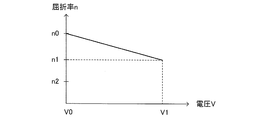
- FIG. 3 is a graph showing a change in the refractive index n of the core 111 with respect to the voltage V applied to the core 111.
- n varies linearly with respect to V.
- the core 101 and the clad 102 of the optical fiber portion 11 can be made of, for example, the same material as the core 111 and the clad 112 of the modulation means 31, respectively.
- the modulation unit 31 includes a first bending portion 110.
- the first bending portion 110 is curved in a certain direction with a certain curvature 1 / R1 (first curvature) (in FIG. 2, the curvature 1 / R1 represents the curvature in the central axis of the core 111).
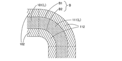
- FIG. 4 is a cross-sectional view of the configuration shown in FIG. 2 cut by a plane including the axis of the core 111. At the boundary surface B between the core 111 and the cladding 112, only the outer edge B1 and the inner edge B2 appear.
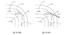
- FIG. 5 is a diagram for explaining how light is reflected and transmitted according to different voltages in the structure of FIG.
- the minimum value of the incident angle ⁇ at which light propagating in the main optical path L is incident on the outer edge B1 is ⁇ min (that is, all light propagating in the main optical path L is incident on the outer edge B1 with an incident angle ⁇ equal to or greater than ⁇ min).
- the refractive index ratio n0 / n2 between the core 111 and the clad 112 is relatively large. For this reason, as shown in FIG.
- the modulation means 31 branches a part of the light from the main optical path L in accordance with the change of the refractive index n in the core 111, thereby modulating the light.
- the presence of a pulse can be represented by branching light, and the absence of a pulse can be represented by not branching light.
- the curvature 1 / R1 (see FIG. 2) of the modulation means 31 is a characteristic of the main optical path L (variation with respect to the refractive index n and voltage V of the core 111, the refractive index n2 of the cladding 112, the minimum value ⁇ min of the incident angle ⁇ , Etc.) can be selected as an angle slightly larger than the critical curvature determined by the above (that is, slightly gentle curvature).
- the “critical curvature” is the maximum curvature within a range where the light incident on the outer edge B1 at the incident angle ⁇ min causes total reflection when the voltage V is the upper limit V1.
- the modulation means 32 and the modulation means 33 also have the same configuration. Therefore, as shown in FIG. 1, the light that has not been branched by the modulation means 31 propagates through the main optical path L and reaches the modulation means 32, and a part of the light branches at the modulation means 32 and leaks outside. Further, the light that has not been branched by the modulation means 32 propagates through the main optical path L and reaches the modulation means 33, and a part of the light branches at the modulation means 33 and leaks outside.
- the upstream modulation means (for example, the modulation means 31) constitutes a part of the main optical path L to the downstream modulation means (for example, the modulation means 32 and the modulation means 33). In this way, a plurality of signals can be extracted from the single light source 60.
- the modulation means located downstream using the light that is not branched by the upstream modulation means modulates.
- light can be supplied to a plurality of modulation means by a single light source 60.
- the configuration of the light source is simplified and the cost can be reduced.
- the optical fiber portion 11 includes a plurality of second bending portions 120.
- the second bending portion 120 is provided in the main optical path L at a position between the modulation means 31 and the modulation means 32, a position between the modulation means 32 and the modulation means 33, and a position downstream of the modulation means 33.
- the second bending portion 120 is curved at a constant curvature 1 / R2 (second curvature) in the same plane as the first bending portion 110 in the opposite direction to the first bending portion 110 (note that FIG. 1, the curvature 1 / R2 represents the curvature in the central axis of the optical fiber portion 11).
- the curvature of the second bending portion 120 is gentler than the curvature of the first bending portion 110 (R1 ⁇ R2), but light propagating through the main optical path L leaks from the second bending portion 120 to the outside. As long as it does not come out, it may not satisfy this condition. That is, the curvature may be larger than the minimum curvature obtained from the refractive index difference between the core 111 and the clad 112. This is because the light propagating through the core 111 is totally reflected if the curvature is larger than the minimum curvature.
- the second bending section 120 is configured such that the branched optical paths L1 to L3 from the respective modulation means are parallel to each other.
- the first bending portion 110 and the propagation direction of the light incident on the modulation means 31, the propagation direction of the light incident on the modulation means 32, and the propagation direction of the light incident on the modulation means 33 are all parallel.
- the second bending portion 120 is configured, and the modulation means 31 to 33 are all arranged in the same direction. According to such a configuration, all the receivers 21 to 23 can be arranged in the same direction, so that the structure of the branched optical paths L1 to L3 and the arrangement of the receivers 21 to 23 can be simplified.
- the most downstream modulation means may not be made of a material whose refractive index changes. .
- it may be a modulation means for performing modulation by transmitting or shielding light according to an applied voltage.
- the second modulation means 32 may be similarly used as such a modulation means.
- the optical fiber portion 11 may not include the second bending portion 120.
- the light branched from each modulation means is not parallel to each other as it is, light can be supplied to a plurality of modulation means by a single light source 60 as in the first embodiment.
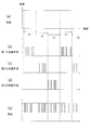
- FIG. The second embodiment specifies the operation timing of each modulation means in the first embodiment.
- FIG. 6 shows the operation timing of each modulation means and the pulse generated in each modulation means (ie, branching in each modulation means) when there is no restriction on the operation timing of each modulation means (an example of the first embodiment described above).
- FIG. 6A shows the intensity of light emitted from the light source 60, which is ideally constant.
- FIGS. 6B to 6D show time widths and intensities of pulses generated by the first modulation unit 31, the second modulation unit 32, and the third modulation unit 33.
- FIG. This pulse corresponds to the light that each modulation means branches from the main optical path L. In this example, each pulse is an ideal rectangle.
- FIG. 6E shows the intensity of light that propagates downstream in the main optical path L from the most downstream modulation means (that is, the modulation means 33), that is, afterglow.
- the first modulation means 31 located on the most upstream side has a uniform pulse waveform and intensity, but as it goes downstream, as shown in FIG. 6 (c) and (d),
- the waveform and intensity of the pulse change under the influence of the upstream branch.
- the pulse P1 and the pulse P2 overlap with each other in time, and 50% of the light in the main optical path L branches as the pulse P1 in the first modulation means 31, and therefore does not reach the second modulation means 32.
- the intensity of the pulse P2 of the second modulation means 32 decreases.
- the pulse P3 and the pulse P4 partially overlap with each other in time, the intensity of the downstream pulse P4 decreases in the overlapping portion, and the waveform is distorted.
- the light from the single light source 60 is taken out by the modulation means 31 to 33 arranged in series in the main optical path L, so that it is the latter stage. Accordingly, the variation of the light intensity in the main optical path L becomes large, and a design in consideration of the reliability of signal transmission is required.
- each modulation means is synchronized and controlled by time division.
- FIG. 7 shows an example of time-sharing control in the second embodiment.
- Each modulation unit branches the light in the main optical path L at different timings according to the control of the control unit 50 (FIG. 1).
- a time zone serving as a unit of control a first time zone T1, a second time zone T2, and a third time zone T3 are provided and arranged in this order so as not to overlap each other.
- Each time zone has an equal length to each other and is repeated with an equal period.
- the next first time zone T1 is arranged immediately after the third time zone T3.
- Each modulation means splits light only in the corresponding time zone. That is, the first modulation means 31 branches light only in the first time zone T1, the second modulation means 32 splits light only in the second time zone T2, and the third modulation means 33 The light is split only in the third time zone T3. Therefore, while a certain modulation means (for example, the second modulation means 32) branches a part of the light in the main optical path L, other modulation means (for example, the first modulation means 31 and the third modulation means 33). ) Will not split the light.
- the modulation means 31 to 33 are synchronized, and the signal transmission timing is time-division controlled. Therefore, the downstream modulation means (for example, the third modulation means 33) is not affected by the upstream modulation means (for example, the first modulation means 31 and the second modulation means 32), and FIG. As shown in d), the quality of the signal from each modulation means can be maintained. In other words, the optical signals transmitted from the modulation means 31 to 33 can be transmitted with the same quality regardless of whether they are upstream or downstream of the main optical path L.
- each time zone is continuous without a gap, but a margin time zone may be provided between each time zone. If control is performed so that none of the modulation means splits light during this margin time, it is possible to more reliably prevent the overlapping of adjacent time zones.
- the lengths of the time zones are equal to each other, but the lengths of the time zones may be different from each other.
- the length of the time zone T1 may be controlled to be greater than the length of the time zone T2. In this way, signals of different rates can be transmitted in parallel.
- Embodiment 3 the operation timing of each modulation means is changed in the second embodiment.
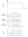
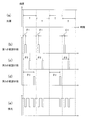
- FIG. 8 shows an example of phase control in the third embodiment.
- Each modulation unit branches the light in the main optical path L at different timings according to the control of the control unit 50 (FIG. 1).
- the cycle of control is T, and this cycle T is repeated. This period T is common to all the modulation means.
- Each modulation means branches light only at a time corresponding to a specific phase in the period T. That is, the first modulation means 31 branches light only at the time corresponding to the phase ⁇ 1 in the period T, the second modulation means 32 branches light only at the time corresponding to the phase ⁇ 2 in the period T, and the third The modulating means 33 branches the light only at the time corresponding to the phase ⁇ 3 in the period T.
- the temporal position of the pulse is determined based on the center of the pulse, but this may be determined based on the start time of the pulse.
- the width of the pulse is designed so that pulses of adjacent periods in the same period T (for example, two pulses corresponding to the phases ⁇ 1 and ⁇ 2) do not interfere with each other.
- a certain modulation unit for example, the second modulation unit 32
- another modulation unit for example, the first modulation unit
- 31 and the third modulation means 33 do not split the light.
- the modulation means 31 to 33 are synchronized, and the signal transmission timing is phase shift controlled. Therefore, as in the second embodiment, the downstream modulation means is not affected by the upstream modulation means, and the quality of the signal from each modulation means is maintained as shown in FIGS. 8B to 8D. Can do. In other words, the optical signals transmitted from the modulation means 31 to 33 can be transmitted with the same quality regardless of whether they are upstream or downstream of the main optical path L.
- each modulation means generates a pulse only at a time corresponding to a specific phase in the period T, so that no pulse is continuously generated from one modulation means.
- a time interval at least equal to the period T between pulses transmitted from one modulation means. Therefore, it is not necessary to increase the reception resolution on the light receiving side.
- the control means 50 on the transmission side it is necessary for the control means 50 on the transmission side to generate a maximum of three pulses in one cycle T, but the receiver 21, receiver 22 and receiver 23 on the reception side each have a cycle. It is only necessary to detect one pulse at the maximum at T.
- the light emitting diode (LED) as the light source is, for example, a non-laser light emitting diode, but may be a laser diode or other light source.
- the core is the refractive index variable unit, and modulation is performed by changing the refractive index of the core in accordance with the voltage.
- the refractive index n of the core decreases from n0 to n1 as the applied voltage V increases, while the refractive index of the cladding is constant at n2.
- the cladding may be a refractive index variable section, and modulation may be performed by changing the refractive index of the cladding according to the voltage.
- PLZT is used as the cladding material so that the refractive index increases as the voltage increases
- the core material uses a material that has a higher refractive index than the cladding and a smaller refractive index variation than the cladding.
Landscapes
- Physics & Mathematics (AREA)
- Nonlinear Science (AREA)
- General Physics & Mathematics (AREA)
- Optics & Photonics (AREA)
- Electromagnetism (AREA)
- Engineering & Computer Science (AREA)
- Computer Networks & Wireless Communication (AREA)
- Signal Processing (AREA)
- Optical Modulation, Optical Deflection, Nonlinear Optics, Optical Demodulation, Optical Logic Elements (AREA)
- Optical Communication System (AREA)
Description
本発明は、光多重通信用の発信機および通信システムに関し、とくに屈折率の変化によって光を変調するものに関する。
光多重通信システムとして、送信データに基づいて生成された駆動電流信号に基づいて光源を制御し、可視光信号を受信機に対して出力するものが提案されている。特許文献1には、光分岐回路を用いて複数の光源を準備し、これらの光源をそれぞれ対応する変調器で並列的に変調する構成が記載されている。
しかしながら、従来の光多重通信システムでは、送信機に用いられる光源を複数準備する必要があった。このため、たとえば構成が複雑になったりコストが増加したりといった問題があった。なお、特許文献1のように単一の光源からの光を分岐させ、擬似的に複数の光源のように扱うことも可能であるが、そのような構成ではそれぞれの変調器に供給される光の強度が低くなる。また、分岐回路が必要になり構成が複雑になる。
本発明は、このような問題を解決するためになされたものであり、光多重通信において、単一の光源を用いて複数の信号を送信することができる発信機および通信システムを提供することを目的とする。
上述の問題を解決するため、この発明に係る光多重通信用の発信機は、光を放出する光源と、光を導く主光路を形成する導光手段と、主光路上に設けられ、第1の信号に応じて光を変調する、第1の変調手段と、主光路上において、第1の変調手段よりも下流に設けられ、第2の信号に応じて光を変調する、第2の変調手段とを備え、第1の変調手段は、屈折率可変部を備える屈折変調手段であり、屈折率可変部は、第1の信号として印加される電圧に応じて屈折率が変化し、屈折変調手段は、屈折率可変部における屈折率の変化に応じて、光の一部を主光路から分岐させ、これによって光を変調する。
このような構成によれば、主光路に複数の変調手段を設け、上流に位置する変調手段が光の一部を主光路から分岐させ、これによって変調を行う。また、下流に位置する変調手段は、上流の変調手段が分岐させなかった光を利用して変調を行う。
導光手段および第1の変調手段は、主光路を形成するコアと、主光路の外周に配置されるクラッドとを備え、屈折率可変部は、コアまたはクラッドとして構成され、電圧は、第1の信号に応じて所定の範囲内で変動し、電圧が範囲内である場合、コアの屈折率は、クラッドの屈折率よりも大きいものであってもよい。
第1の変調手段は主光路に沿って延び、第1の変調手段は、第1の曲率で湾曲する第1湾曲部を備え、電圧が範囲の下限である場合、主光路を伝播する光は、第1湾曲部におけるコアとクラッドとの境界面において全反射を起こし、電圧が範囲の上限である場合、主光路を伝播する光の一部が境界面を透過し、これによって主光路から分岐してもよい。
導光手段は、第1の曲率よりも小さい第2の曲率で湾曲する第2湾曲部を備え、湾曲部および第1の変調手段のコアは、同一平面内において互いに逆の向きに湾曲してもよい。
第1の変調手段は、第1の信号に応じて屈折率可変部に印加される電圧を変化させてもよい。
第2の変調手段は屈折変調手段であってもよい。
光源はレーザーダイオードであり、導光手段は光ファイバであってもよい。
第2の変調手段は、屈折変調手段であり、第1および第2の変調手段は、それぞれ異なるタイミングで光を分岐させてもよい。
第1の変調手段および第2の変調手段は、それぞれ第1の時間帯および第2の時間帯において光を分岐させ、第1の時間帯および第2の時間帯は、互いに等しい周期で繰り返されてもよい。
第1の変調手段および第2の変調手段は、それぞれ、共通の時間周期における第1の位相時刻および第2の位相時刻において光を分岐させてもよい。
第1の変調手段は主光路に沿って延び、第1の変調手段は、第1の曲率で湾曲する第1湾曲部を備え、電圧が範囲の下限である場合、主光路を伝播する光は、第1湾曲部におけるコアとクラッドとの境界面において全反射を起こし、電圧が範囲の上限である場合、主光路を伝播する光の一部が境界面を透過し、これによって主光路から分岐してもよい。
導光手段は、第1の曲率よりも小さい第2の曲率で湾曲する第2湾曲部を備え、湾曲部および第1の変調手段のコアは、同一平面内において互いに逆の向きに湾曲してもよい。
第1の変調手段は、第1の信号に応じて屈折率可変部に印加される電圧を変化させてもよい。
第2の変調手段は屈折変調手段であってもよい。
光源はレーザーダイオードであり、導光手段は光ファイバであってもよい。
第2の変調手段は、屈折変調手段であり、第1および第2の変調手段は、それぞれ異なるタイミングで光を分岐させてもよい。
第1の変調手段および第2の変調手段は、それぞれ第1の時間帯および第2の時間帯において光を分岐させ、第1の時間帯および第2の時間帯は、互いに等しい周期で繰り返されてもよい。
第1の変調手段および第2の変調手段は、それぞれ、共通の時間周期における第1の位相時刻および第2の位相時刻において光を分岐させてもよい。
また、この発明に係る通信システムは、上述の発信機と、第1の変調手段によって分岐させられた光を受光する光検出手段と、光検出手段が受光した光を復調して第1の信号を再生する復調手段とを備える。
本発明の発信機および通信システムによれば、上流の変調手段が分岐させなかった光を利用して下流に位置する変調手段が変調を行うので、単一の光源によって複数の変調手段に光を供給することができる。このため、たとえば光源の構成が簡素になり、またコストを低減できる。
以下、この発明の実施の形態を添付図面に基づいて説明する。
実施の形態1.
図1は、本発明の実施の形態1に係る光多重通信システム1の構成の概略を示す模式図である。本発明に係る光多重通信システム1は、発信機10および受信機21~23を備える。発信機10は、光ファイバ部11と、光ファイバ部11に設けられる複数の変調手段(第1の変調手段31、第2の変調手段32および第3の変調手段33)と、これらの変調手段にそれぞれ信号を供給する信号源(第1の信号源41、第2の信号源42および第3の信号源43)と、各信号源を制御する制御手段50と、光ファイバ部11に光を供給する光源60とを備える。
実施の形態1.
図1は、本発明の実施の形態1に係る光多重通信システム1の構成の概略を示す模式図である。本発明に係る光多重通信システム1は、発信機10および受信機21~23を備える。発信機10は、光ファイバ部11と、光ファイバ部11に設けられる複数の変調手段(第1の変調手段31、第2の変調手段32および第3の変調手段33)と、これらの変調手段にそれぞれ信号を供給する信号源(第1の信号源41、第2の信号源42および第3の信号源43)と、各信号源を制御する制御手段50と、光ファイバ部11に光を供給する光源60とを備える。
光源60はたとえば発光ダイオード(LED)であり、光を放出して光ファイバ部11に入射させる。光ファイバ部11は、入射した光を軸方向に導く主光路Lを形成する導光手段として機能する。変調手段31~33は、主光路L上に上流から下流に向かう順で設けられる。すなわち、主光路L上において、変調手段31が最も上流に設けられ、変調手段32は変調手段31よりも下流に設けられ、さらに変調手段33は変調手段32よりも下流に設けられる。また、変調手段31~33は、それぞれ入力される信号(第1の信号、第2の信号および第3の信号)に応じて光を変調する。
変調手段31~33によって変調された光は、主光路Lからそれぞれ対応する分岐光路(第1の分岐光路L1、第2の分岐光路L2および第3の分岐光路L3)に分岐する(分岐の動作については後述する)。受信機21~23は、それぞれ、変調手段31~33によって分岐光路L1~L3に分岐させられた光を受光する。たとえば受信機21は分岐光路L1を伝播する光を受光する第1の光検出手段を備える。この光検出手段は、公知のMOSやCCDを用いた受光素子等によって構成することができる。また、受信機21は、受光した光を復調して第1の信号を再生する第1の復調手段を備える。
受信機22および受信機23も、受信機21と同様の構成を備える。このような構成により、光多重通信システム1は、単一の光源60からの光を利用し、複数の変調手段31~33と複数の受信機21~23との間で多重通信を行う。
図2は、光ファイバ部11および変調手段31~33に関連する構成を説明する拡大図である。なお、図2には変調手段31のみを示すが、本実施形態では変調手段32および変調手段33も変調手段31と同様の構成を有する。
光ファイバ部11は公知の光ファイバとしての構成を有する。たとえば、主光路Lを形成するコア101と、コア101の外周に配置されるクラッド102とを備える。また、変調手段31は主光路Lに沿って延びる形状を有し、主光路Lを形成するコア111と、コア111の外周に配置されるクラッド112とを備える。クラッド112はコア111を包むように存在する。
変調手段31のコア111は、透明性(すなわち光伝導性)を持ち、電圧の印加により屈折率が変化する材料によって構成される。すなわち、本実施形態では、コア111は屈折率可変部であり、変調手段31は屈折変調手段である。このような材料としては、たとえばPLZTを用いることができる。また変調手段31のクラッド112は、コア111よりも屈折率が低い材料によって構成される。
クラッド112には一対の電極140が設けられる。図2にはこのうち一方(たとえば陽極)のみを示すが、コア111およびクラッド112に対してこれと反対の位置にもう一方の電極(たとえば陰極)が同様の構成で設けられる。一対の電極140は信号源41に接続され、信号源41が発生する電圧をコア111およびクラッド112に印加する。このように、信号源41および電極140は、第1の信号に応じて、コア111およびクラッド112に印加される電圧を変化させる、電圧印加部として機能する。また、これに伴い、印加される電圧に応じてコア111およびクラッド112の屈折率が変化する。なお、電圧の印加による屈折率の変化量はコア111とクラッド112とでは異なる。本実施形態では上述のようにコア111の材料にPLZTが用いられており、コア111の屈折率変化はクラッド112よりも大きい。
なお、図2では電極140およびその周辺部分にはクラッド112が設けられず、コア
111に直接電極140が接触しているが、電極140はクラッド112を介して取り付けられてもよい。
なお、図2では電極140およびその周辺部分にはクラッド112が設けられず、コア
111に直接電極140が接触しているが、電極140はクラッド112を介して取り付けられてもよい。
図3は、コア111に印加される電圧Vに対するコア111の屈折率nの変化を表すグラフである。第1の入力信号に応じて信号源41が発生する電圧(または電圧の絶対値)の下限をV0(たとえばV0=0)とし、上限をV1とする。すなわち、コア111に印加される電圧VはV0≦V≦V1の範囲内で変動する。
V=V0のときn=n0であり、V=V1のときn=n1である。V0<V<V1のときn0<n<n1であり、たとえばnはVに対して線形に変化する。また、クラッド112の屈折率をn2とすると、V0≦V≦V1であれば常にn>n2である。(なお、本実施形態ではn2は常に一定とするが、V0≦V≦V1においてn>n2を満たすものであればn2は一定でなくともよい。)
また、光ファイバ部11のコア101およびクラッド102は、たとえばそれぞれ変調手段31のコア111およびクラッド112と同一の材料によって構成することができる。
V=V0のときn=n0であり、V=V1のときn=n1である。V0<V<V1のときn0<n<n1であり、たとえばnはVに対して線形に変化する。また、クラッド112の屈折率をn2とすると、V0≦V≦V1であれば常にn>n2である。(なお、本実施形態ではn2は常に一定とするが、V0≦V≦V1においてn>n2を満たすものであればn2は一定でなくともよい。)
また、光ファイバ部11のコア101およびクラッド102は、たとえばそれぞれ変調手段31のコア111およびクラッド112と同一の材料によって構成することができる。
図2に戻る。変調手段31は、第1湾曲部110を備える。第1湾曲部110は、一定の向きに一定の曲率1/R1(第1の曲率)で湾曲している(なお図2では曲率1/R1はコア111の中心軸における曲率を表す)。
図4は、図2に示す構成を、コア111の軸を含む平面によって切断した断面図である。コア111とクラッド112との境界面Bは、その外縁B1および内縁B2のみが現れている。
図4は、図2に示す構成を、コア111の軸を含む平面によって切断した断面図である。コア111とクラッド112との境界面Bは、その外縁B1および内縁B2のみが現れている。
図5は、図4の構造において、異なる電圧に応じた光の反射および透過の様子を説明する図である。図5(a)はV=V0の状態を示し、図5(b)はV=V1の状態を示す。主光路Lを伝播する光が外縁B1に入射する入射角θの最小値をθminとする(すなわち、主光路Lを伝播する光はすべてθmin以上の入射角θをもって外縁B1に入射する)。V=V0の場合、図3に示すようにコア111とクラッド112の屈折率の比n0/n2は比較的大きい。このため、図5(a)のように、主光路Lから外縁B1に入射角θminで入射した光が、外縁B1で全反射を起こし、分岐せずに主光路L内にとどまるように設計可能である。なおθ>θminとなる場合も同様であるので、主光路L内を伝播する光は外部に漏れず主光路L内を伝播し続けることになる。
一方、V=V1の場合、図3に示すようにコア111とクラッド112の屈折率の比n1/n2は比較的小さい。このため、全反射の臨界角が広角側にシフトし、θminよりも大きくなる(なおθminは図5(a)の場合と図5(b)の場合とで同一の値である)。すなわち、図5(b)のように、主光路Lから外縁B1に入射角θminで入射した光の一部が外縁B1を透過し、これによって主光路Lから分岐光路L1へと分岐して漏れ出すように設計可能である。
このように、変調手段31は、コア111における屈折率nの変化に応じて、光の一部を主光路Lから分岐させ、これによって光を変調する。たとえば、光を分岐させることによってパルスが存在することを表し、光を分岐させないことによってパルスが存在しないことを表すことができる。
なお、変調手段31の曲率1/R1(図2参照)は、主光路Lの特性(コア111の屈折率nおよび電圧Vに対する変動、クラッド112の屈折率n2、入射角θの最小値θmin、等)によって決まる臨界曲率より若干大きめの角度(すなわち若干ゆるやかな曲率)として選択することができる。ここで、「臨界曲率」とは、電圧Vが上限V1である場合に、入射角θminで外縁B1に入射した光が全反射を起こす範囲内で最大の曲率である。
また、V=V1のときに主光路Lから分岐する光の割合は曲率および屈折率等の諸条件によって定まり、たとえば30%程度の光が分岐する構成とすることができる。
また、V=V1のときに主光路Lから分岐する光の割合は曲率および屈折率等の諸条件によって定まり、たとえば30%程度の光が分岐する構成とすることができる。
以上は変調手段31の構成であるが、変調手段32および変調手段33も同様の構成を有する。したがって、図1に示すように、変調手段31において分岐しなかった光は主光路Lを伝播して変調手段32に達し、その一部は変調手段32において分岐して外部に漏れ出す。さらに、変調手段32でも分岐しなかった光は主光路Lを伝播して変調手段33に達し、その一部は変調手段33において分岐して外部に漏れ出す。すなわち、上流の変調手段(たとえば変調手段31)は、下流の変調手段(たとえば変調手段32および変調手段33)までの主光路Lの一部を構成する。このように、単一の光源60から複数の信号を取り出すことが可能となる。
以上のように、本発明の実施の形態1に係る発信機10および光多重通信システム1によれば、上流の変調手段が分岐させなかった光を利用して下流に位置する変調手段が変調を行うので、単一の光源60によって複数の変調手段に光を供給することができる。このため、たとえば光源の構成が簡素になり、またコストを低減できる。
また、図1に示すように、光ファイバ部11は複数の第2湾曲部120を備える。第2湾曲部120は、主光路Lにおいて、変調手段31と変調手段32の間の位置、変調手段32と変調手段33との間の位置、および変調手段33よりも下流の位置に設けられる。 第2湾曲部120は、第1湾曲部110と同一の平面において、第1湾曲部110とは反対の向きに、一定の曲率1/R2(第2の曲率)で湾曲している(なお図1では曲率1/R2は光ファイバ部11の中心軸における曲率を表す)。なお、本実施形態では第2湾曲部120の曲率は第1湾曲部110の曲率よりもゆるやかである(R1<R2)が、主光路Lを伝播する光が第2湾曲部120から外部に漏れ出さない範囲であればこの条件を満たさないものであってもよい。すなわち、コア111およびクラッド112の屈折率差から求められる最小曲率よりも大きな曲率であればよい。最小曲率よりも大きな曲率であればコア111を伝播する光が全反射するからである。
また、第2湾曲部120は、各変調手段からの分岐光路L1~L3が互いに平行となるように構成される。たとえば、変調手段31に入射する光の伝播方向と、変調手段32に入射する光の伝播方向と、変調手段33に入射する光の伝播方向とがすべて平行となるように第1湾曲部110および第2湾曲部120を構成し、さらに変調手段31~33をすべて同じ向きに配置する。このような構成によれば、受信機21~23をすべて同じ向きに配置できるので、分岐光路L1~L3の構造および受信機21~受信機23の配置を簡素にすることができる。
上述の実施の形態1において、以下のような変形を施すことができる。
最下流の変調手段(第3の変調手段33)よりも下流では主光路Lを維持する必要がないので、最下流の変調手段は、屈折率が変化する材料によって構成されたものでなくともよい。たとえば、印加される電圧に応じて光を透過または遮蔽することによって変調を行う変調手段であってもよい。また、第3の変調手段33を設けない場合には、同様に第2の変調手段32をそのような変調手段としてもよい。
最下流の変調手段(第3の変調手段33)よりも下流では主光路Lを維持する必要がないので、最下流の変調手段は、屈折率が変化する材料によって構成されたものでなくともよい。たとえば、印加される電圧に応じて光を透過または遮蔽することによって変調を行う変調手段であってもよい。また、第3の変調手段33を設けない場合には、同様に第2の変調手段32をそのような変調手段としてもよい。
光ファイバ部11は、第2湾曲部120を備えないものであってもよい。この場合には、各変調手段から分岐する光がそのままでは互いに平行とならないが、実施の形態1と同様に単一の光源60によって複数の変調手段に光を供給することができる。
実施の形態2.
実施の形態2は、実施の形態1において、各変調手段の動作タイミングを特定するものである。
図6は、各変調手段の動作タイミングに制限を設けない場合(上述の実施の形態1の一例)において、各変調手段の動作タイミングと、各変調手段において発生するパルス(すなわち各変調手段において分岐する光の強度)との関係の例を示す。この例では、説明の便宜上、各変調手段はいずれも光の50%を分岐させるように示しているが、実際に分岐する光はたとえば30%程度である。
実施の形態2は、実施の形態1において、各変調手段の動作タイミングを特定するものである。
図6は、各変調手段の動作タイミングに制限を設けない場合(上述の実施の形態1の一例)において、各変調手段の動作タイミングと、各変調手段において発生するパルス(すなわち各変調手段において分岐する光の強度)との関係の例を示す。この例では、説明の便宜上、各変調手段はいずれも光の50%を分岐させるように示しているが、実際に分岐する光はたとえば30%程度である。
図6(a)は光源60が放出する光の強度であり、理想的には一定である。図6(b)~(d)は、第1の変調手段31、第2の変調手段32および第3の変調手段33が発生するパルスの時間幅および強度を示す。このパルスは、各変調手段が主光路Lから分岐させる光に対応する。この例では各パルスは理想的な矩形であるものとする。図6(e)は、主光路Lにおいて最下流の変調手段(すなわち変調手段33)よりも下流まで伝播する光、すなわち残光の強度である。
図6(b)のように、最上流に位置する第1の変調手段31ではパルスの波形および強度は均一であるが、下流に進むにつれ、図6(c)および(d)のように、上流での分岐の影響を受けてパルスの波形および強度が変化する。たとえばパルスP1とパルスP2は時間的に重複しており、主光路Lの光の50%が第1の変調手段31においてパルスP1として分岐し、このため第2の変調手段32には到達しないので、第2変調手段32のパルスP2は強度が落ちる。同様に、パルスP3とパルスP4は一部が時間的に重複しているので、重複している部分について下流のパルスP4の強度が落ち、波形が歪む。
このように、各変調手段の動作タイミングに制限を設けない場合には、単一の光源60からの光が主光路Lに直列に配置された変調手段31~33において取り出されるので、後段になるに従って主光路L内の光強度のばらつきが大きくなり、信号伝達の信頼性を考慮した設計が必要となる。
これに対し、実施の形態2では、各変調手段の動作タイミングを制御する。たとえば、各変調手段を同期させ時分割で制御する。
図7は、実施の形態2における時分割制御の例を示す。各変調手段は、制御手段50(図1)の制御に応じ、それぞれ異なるタイミングで主光路Lの光を分岐させる。制御の単位となる時間帯として、第1の時間帯T1、第2の時間帯T2および第3の時間帯T3が設けられ、この順に、互いに重複しないように配置される。
各時間帯は互いに等しい長さを有し、また、等しい周期で繰り返される。本実施形態では、第3の時間帯T3の直後に次の第1の時間帯T1が配置されている。
図7は、実施の形態2における時分割制御の例を示す。各変調手段は、制御手段50(図1)の制御に応じ、それぞれ異なるタイミングで主光路Lの光を分岐させる。制御の単位となる時間帯として、第1の時間帯T1、第2の時間帯T2および第3の時間帯T3が設けられ、この順に、互いに重複しないように配置される。
各時間帯は互いに等しい長さを有し、また、等しい周期で繰り返される。本実施形態では、第3の時間帯T3の直後に次の第1の時間帯T1が配置されている。
各変調手段は、それぞれ対応する時間帯においてのみ光を分岐させる。すなわち、第1の変調手段31は第1の時間帯T1においてのみ光を分岐させ、第2の変調手段32は第2の時間帯T2においてのみ光を分岐させ、第3の変調手段33は第3の時間帯T3においてのみ光を分岐させる。したがって、ある変調手段(たとえば第2の変調手段32)が主光路Lの光の一部を分岐させている間は、他の変調手段(たとえば第1の変調手段31および第3の変調手段33)は光を分岐させないことになる。
以上のように、実施の形態2では、変調手段31~33を同期させ、信号を送るタイミングを時分割制御する。よって、下流の変調手段(たとえば第3の変調手段33)は、上流の変調手段(たとえば第1の変調手段31および第2の変調手段32)によって影響を受けず、図7(b)~(d)に示すように各変調手段からの信号の品質を維持することができる。すなわち、変調手段31~33から送信される光信号を、主光路Lの上流・下流を問わず同等の品質で送信することが可能になる。
なお、上述の実施の形態2では各時間帯が隙間なく連続しているが、各時間帯の間には余裕時間帯が設けられても良い。この余裕時間にはいずれの変調手段も光を分岐させない制御とすれば、隣接する時間帯の重複をより確実に防止することができる。
また、実施の形態2では各時間帯の長さが互いに等しいが、各時間帯の長さが互いに異なっていてもよい。たとえば、時間帯T1の長さが時間帯T2の長さより大きくなるよう制御してもよい。このようにすると、異なるレートの信号を並列して送信することができる。
実施の形態3.
実施の形態3は、実施の形態2において、各変調手段の動作タイミングを変更するものである。
図8は、実施の形態3における位相制御の例を示す。各変調手段は、制御手段50(図1)の制御に応じ、それぞれ異なるタイミングで主光路Lの光を分岐させる。制御の周期はTであり、この周期Tが繰り返される。この周期Tは、すべての変調手段について共通である。
実施の形態3は、実施の形態2において、各変調手段の動作タイミングを変更するものである。
図8は、実施の形態3における位相制御の例を示す。各変調手段は、制御手段50(図1)の制御に応じ、それぞれ異なるタイミングで主光路Lの光を分岐させる。制御の周期はTであり、この周期Tが繰り返される。この周期Tは、すべての変調手段について共通である。
各変調手段は、周期Tにおける特定の位相に対応する時刻においてのみ光を分岐させる。すなわち、第1の変調手段31は周期Tにおける位相θ1に相当する時刻においてのみ光を分岐させ、第2の変調手段32は周期Tにおける位相θ2に相当する時刻においてのみ光を分岐させ、第3の変調手段33は周期Tにおける位相θ3に相当する時刻においてのみ光を分岐させる。なお、図8ではパルスの時間的位置はパルスの中央を基準として決められるが、これはパルスの開始時点等を基準として決めてもよい。また、パルスの幅は、同一の周期Tにおける隣接する周期のパルス(たとえば位相θ1およびθ2に対応する2つのパルス)が互いに干渉しないよう設計される。
したがって、実施の形態2と同様に、ある変調手段(たとえば第2の変調手段32)が主光路Lの光の一部を分岐させている間は、他の変調手段(たとえば第1の変調手段31および第3の変調手段33)は光を分岐させないことになる。
以上のように、実施の形態3では、変調手段31~33を同期させ、信号を送るタイミングを位相シフト制御する。よって、実施の形態2と同様に、下流の変調手段は上流の変調手段によって影響を受けず、図8(b)~(d)に示すように各変調手段からの信号の品質を維持することができる。すなわち、変調手段31~33から送信される光信号を、主光路Lの上流・下流を問わず同等の品質で送信することが可能になる。
また、実施の形態3では、各変調手段は周期Tのうち特定の位相に対応する時刻においてのみパルスを発生させるので、ひとつの変調手段から連続してパルスが発生することがない。たとえば図8(b)~(d)から明らかなように、ひとつの変調手段から送信されるパルスの間には少なくとも周期Tに等しい時間間隔が存在することになる。したがって、受光側の受信分解能を高める必要がない。たとえば図8に示す場合では、送信側の制御手段50は1つの周期Tにおいて最大で3つのパルスを発生させる必要があるが、受信側の受信機21、受信機22および受信機23はそれぞれ周期Tにおいて最大で1つのパルスを検出できればよい。
実施の形態1~3において、光源としての発光ダイオード(LED)はたとえば非レーザーの発光ダイオードであるが、レーザーダイオードであってもよく、その他の光源であってもよい。
実施の形態1~3では、コアが屈折率可変部であり、コアの屈折率を電圧に応じて変化させることで変調を行っている。たとえば、図3の例では、印加される電圧Vの増加に応じてコアの屈折率nがn0からn1に減少する一方、クラッドの屈折率はn2で一定である。
変形例として、クラッドを屈折率可変部とし、クラッドの屈折率を電圧に応じて変化させることで変調を行ってもよい。たとえば、クラッドの材料にPLZTを用いて、電圧の増加に応じて屈折率が増加するよう構成し、コアの材料にはクラッドより屈折率が大きくクラッドより屈折率変化量が小さい材料を用いることで、このような構成を実現することができる。
変形例として、クラッドを屈折率可変部とし、クラッドの屈折率を電圧に応じて変化させることで変調を行ってもよい。たとえば、クラッドの材料にPLZTを用いて、電圧の増加に応じて屈折率が増加するよう構成し、コアの材料にはクラッドより屈折率が大きくクラッドより屈折率変化量が小さい材料を用いることで、このような構成を実現することができる。
Claims (11)
- 光を放出する光源と、
前記光を導く主光路を形成する導光手段と、
前記主光路上に設けられ、第1の信号に応じて前記光を変調する、第1の変調手段と、
前記主光路上において、前記第1の変調手段よりも下流に設けられ、第2の信号に応じて前記光を変調する、第2の変調手段と
を備え、
前記第1の変調手段は、屈折率可変部を備える屈折変調手段であり、
前記屈折率可変部は、前記第1の信号として印加される電圧に応じて屈折率が変化し、
前記屈折変調手段は、前記屈折率可変部における屈折率の変化に応じて、前記光の一部を前記主光路から分岐させ、これによって前記光を変調する
光多重通信用の発信機。 - 前記導光手段および前記第1の変調手段は、前記主光路を形成するコアと、前記主光路の外周に配置されるクラッドとを備え、
前記屈折率可変部は、前記コアまたは前記クラッドとして構成され、
前記電圧は、前記第1の信号に応じて所定の範囲内で変動し、
前記電圧が前記範囲内である場合、前記コアの屈折率は、前記クラッドの屈折率よりも大きい、請求項1に記載の発信機。 - 前記第1の変調手段は前記主光路に沿って延び、
前記第1の変調手段は、第1の曲率で湾曲する第1湾曲部を備え、
前記電圧が前記範囲の下限である場合、前記主光路を伝播する光は、前記第1湾曲部における前記コアと前記クラッドとの境界面において全反射を起こし、
前記電圧が前記範囲の上限である場合、前記主光路を伝播する光の一部が前記境界面を透過し、これによって前記主光路から分岐する、請求項2に記載の発信機。 - 前記導光手段は、前記第1の曲率よりも小さい第2の曲率で湾曲する第2湾曲部を備え、
前記第1湾曲部および前記第2湾曲部は、同一平面内において互いに逆の向きに湾曲する、請求項3に記載の発信機。 - 前記第1の変調手段は、前記第1の信号に応じて前記屈折率可変部に印加される電圧を変化させる電圧印加部を備える、請求項1に記載の発信機。
- 前記第2の変調手段は前記屈折変調手段である、請求項1に記載の発信機。
- 前記光源は発光ダイオードであり、前記導光手段は光ファイバである、請求項1に記載の発信機。
- 前記第2の変調手段は、前記屈折変調手段であり、
前記第1および第2の変調手段は、それぞれ異なるタイミングで前記光を分岐させる、請求項1に記載の発信機。 - 前記第1の変調手段および前記第2の変調手段は、それぞれ第1の時間帯および第2の時間帯において前記光を分岐させ、
前記第1の時間帯および前記第2の時間帯は、互いに等しい周期で繰り返される、請求項8に記載の発信機。 - 前記第1の変調手段および前記第2の変調手段は、それぞれ、共通の時間周期における第1の位相時刻および第2の位相時刻において前記光を分岐させる、請求項8に記載の発信機。
- 請求項1に記載の発信機と、
前記第1の変調手段によって分岐させられた光を受光する光検出手段と、
前記光検出手段が受光した光を復調して前記第1の信号を再生する復調手段と
を備える通信システム。
Applications Claiming Priority (2)
| Application Number | Priority Date | Filing Date | Title |
|---|---|---|---|
| JP2012086048A JP6031803B2 (ja) | 2012-04-05 | 2012-04-05 | 光多重通信用の発信機および通信システム |
| JP2012-086048 | 2012-04-05 |
Publications (1)
| Publication Number | Publication Date |
|---|---|
| WO2013150873A1 true WO2013150873A1 (ja) | 2013-10-10 |
Family
ID=49300368
Family Applications (1)
| Application Number | Title | Priority Date | Filing Date |
|---|---|---|---|
| PCT/JP2013/057157 Ceased WO2013150873A1 (ja) | 2012-04-05 | 2013-03-14 | 光多重通信用の発信機および通信システム |
Country Status (2)
| Country | Link |
|---|---|
| JP (1) | JP6031803B2 (ja) |
| WO (1) | WO2013150873A1 (ja) |
Families Citing this family (1)
| Publication number | Priority date | Publication date | Assignee | Title |
|---|---|---|---|---|
| KR102643708B1 (ko) * | 2017-06-09 | 2024-03-04 | 오피이 엘엘씨 | 아날로그 콤포넌트를 갖는 데이터 보안 장치 |
Citations (2)
| Publication number | Priority date | Publication date | Assignee | Title |
|---|---|---|---|---|
| JPH0643504A (ja) * | 1992-04-07 | 1994-02-18 | Sharp Corp | 光スイッチ素子及びそれに用いられる液晶光方向性結合器 |
| JPH1098439A (ja) * | 1996-09-20 | 1998-04-14 | Oki Electric Ind Co Ltd | 光信号送信装置、光信号受信装置及び光信号送受信装置 |
Family Cites Families (1)
| Publication number | Priority date | Publication date | Assignee | Title |
|---|---|---|---|---|
| JPH03145628A (ja) * | 1989-11-01 | 1991-06-20 | Sumitomo Electric Ind Ltd | 光スイッチ |
-
2012
- 2012-04-05 JP JP2012086048A patent/JP6031803B2/ja not_active Expired - Fee Related
-
2013
- 2013-03-14 WO PCT/JP2013/057157 patent/WO2013150873A1/ja not_active Ceased
Patent Citations (2)
| Publication number | Priority date | Publication date | Assignee | Title |
|---|---|---|---|---|
| JPH0643504A (ja) * | 1992-04-07 | 1994-02-18 | Sharp Corp | 光スイッチ素子及びそれに用いられる液晶光方向性結合器 |
| JPH1098439A (ja) * | 1996-09-20 | 1998-04-14 | Oki Electric Ind Co Ltd | 光信号送信装置、光信号受信装置及び光信号送受信装置 |
Non-Patent Citations (1)
| Title |
|---|
| D. H. MCMAHON: "Multimode optical switching", LASER FOCUS WITH FIBEROPTIC COMMUNICAIONS, vol. 15, no. 3, March 1979 (1979-03-01), pages 46 - 64 * |
Also Published As
| Publication number | Publication date |
|---|---|
| JP6031803B2 (ja) | 2016-11-24 |
| JP2013217998A (ja) | 2013-10-24 |
Similar Documents
| Publication | Publication Date | Title |
|---|---|---|
| JP5070853B2 (ja) | 光デバイス | |
| JP4083657B2 (ja) | 光変調器のバイアス制御方法及びその装置 | |
| US7876491B2 (en) | Multilevel optical phase modulator | |
| JP6120761B2 (ja) | 光送信器および光送信器の制御方法 | |
| EP2148457A2 (en) | Optical transmitter | |
| EP2015130A1 (en) | Optical waveguide device based on a delay interferometer for transmitting return-to-zero pulses | |
| US10254623B2 (en) | Mach-zehnder (MZ) ring optical modulator | |
| JP6031803B2 (ja) | 光多重通信用の発信機および通信システム | |
| JPH10221664A (ja) | 光変調器 | |
| JP5768020B2 (ja) | 光変調装置およびそのドリフト制御方法 | |
| JP2014112168A (ja) | 光変調器及び光送信機 | |
| JP5076726B2 (ja) | 光変調器および光送信器 | |
| JP5403098B2 (ja) | 光デバイス | |
| JP6385848B2 (ja) | 光変調器 | |
| JP2006251804A (ja) | 電気光学遅延線周波数弁別器 | |
| CA2057572C (en) | Optical transmitter | |
| JP7695587B2 (ja) | 制御回路及び光回路制御方法 | |
| US10247967B2 (en) | Optical modulator having Mach-Zehnder diodes of reduced length | |
| US7957646B2 (en) | Optical time division multiplexing transmitter | |
| JP4580333B2 (ja) | 光送信装置、および光位相変調器 | |
| JP5001245B2 (ja) | 光強度変調器のバイアス制御装置 | |
| JP2675033B2 (ja) | 分布干渉型光変調器 | |
| JP2008242243A (ja) | 光導波路素子、及び光導波路素子の光クロストーク抑止方法 | |
| JP2014122964A (ja) | 光変調器、光送信器、光送受信システム及び光変調器の制御方法 | |
| US10761352B1 (en) | Optical device |
Legal Events
| Date | Code | Title | Description |
|---|---|---|---|
| 121 | Ep: the epo has been informed by wipo that ep was designated in this application |
Ref document number: 13772598 Country of ref document: EP Kind code of ref document: A1 |
|
| NENP | Non-entry into the national phase |
Ref country code: DE |
|
| 122 | Ep: pct application non-entry in european phase |
Ref document number: 13772598 Country of ref document: EP Kind code of ref document: A1 |