WO2013150846A1 - 紫外線放射蛍光ランプ - Google Patents
紫外線放射蛍光ランプ Download PDFInfo
- Publication number
- WO2013150846A1 WO2013150846A1 PCT/JP2013/055351 JP2013055351W WO2013150846A1 WO 2013150846 A1 WO2013150846 A1 WO 2013150846A1 JP 2013055351 W JP2013055351 W JP 2013055351W WO 2013150846 A1 WO2013150846 A1 WO 2013150846A1
- Authority
- WO
- WIPO (PCT)
- Prior art keywords
- arc tube
- uvc
- light
- fluorescent lamp
- ultraviolet
- Prior art date
- Legal status (The legal status is an assumption and is not a legal conclusion. Google has not performed a legal analysis and makes no representation as to the accuracy of the status listed.)
- Ceased
Links
Images

Classifications
-
- H—ELECTRICITY
- H01—ELECTRIC ELEMENTS
- H01J—ELECTRIC DISCHARGE TUBES OR DISCHARGE LAMPS
- H01J61/00—Gas-discharge or vapour-discharge lamps
- H01J61/02—Details
- H01J61/30—Vessels; Containers
- H01J61/35—Vessels; Containers provided with coatings on the walls thereof; Selection of materials for the coatings
-
- H—ELECTRICITY
- H01—ELECTRIC ELEMENTS
- H01J—ELECTRIC DISCHARGE TUBES OR DISCHARGE LAMPS
- H01J61/00—Gas-discharge or vapour-discharge lamps
- H01J61/02—Details
- H01J61/025—Associated optical elements
-
- H—ELECTRICITY
- H01—ELECTRIC ELEMENTS
- H01J—ELECTRIC DISCHARGE TUBES OR DISCHARGE LAMPS
- H01J61/00—Gas-discharge or vapour-discharge lamps
- H01J61/02—Details
- H01J61/38—Devices for influencing the colour or wavelength of the light
- H01J61/42—Devices for influencing the colour or wavelength of the light by transforming the wavelength of the light by luminescence
- H01J61/44—Devices characterised by the luminescent material
-
- H—ELECTRICITY
- H01—ELECTRIC ELEMENTS
- H01J—ELECTRIC DISCHARGE TUBES OR DISCHARGE LAMPS
- H01J65/00—Lamps without any electrode inside the vessel; Lamps with at least one main electrode outside the vessel
- H01J65/04—Lamps in which a gas filling is excited to luminesce by an external electromagnetic field or by external corpuscular radiation, e.g. for indicating plasma display panels
- H01J65/042—Lamps in which a gas filling is excited to luminesce by an external electromagnetic field or by external corpuscular radiation, e.g. for indicating plasma display panels by an external electromagnetic field
- H01J65/046—Lamps in which a gas filling is excited to luminesce by an external electromagnetic field or by external corpuscular radiation, e.g. for indicating plasma display panels by an external electromagnetic field the field being produced by using capacitive means around the vessel
Definitions
- the present invention relates to an ultraviolet radiation fluorescent lamp that emits light in the ultraviolet region, and more particularly, to an ultraviolet radiation fluorescent lamp used for removing organic contaminants of an artificial tooth root used for dental implants.
- Patent Document 1 Japanese Patent Application Publication No. 2005-505352
- Patent Document 1 Japanese Patent Application Publication No. 2005-505352
- the physical and chemical characteristics of the surface of the artificial tooth root are improved, and an increase in binding ability to a living body is promoted.
- the artificial tooth root material is irradiated with ultraviolet rays to remove the carbon adsorbed on the surface, changing the state of the artificial tooth root surface from water-repellent to hydrophilic, not only water.
- the purpose is to improve the affinity for blood, and promptly establish the artificial tooth root in the human body.
- Such an optical function obtained by irradiating titanium with ultraviolet rays has attracted attention as an effective technique for removing adsorbed materials against a phenomenon in which carbon adsorbs on the titanium surface over time (titanium aging phenomenon).
- the ultraviolet ray suitable in the above-mentioned Patent Document 1 is an ultraviolet ray having a relatively short wavelength, and it is effective that the wavelength is 200 nm or less.
- handling a light source that emits vacuum ultraviolet light in a general medical field involves the danger of workers, and therefore, the present applicant has disclosed more safety in Japanese Patent Application Laid-Open No. 2012-000118 (Patent Document 2) and the like. Proposal has been made on an organic material removal device for artificial tooth roots that can be reliably irradiated with ultraviolet rays.
- the adhesion (bonding) characteristic at the interface between titanium and the living tissue embedded in the living body as an artificial tooth root is greatly related to the initial surface state of titanium.
- the wavelength of the titanium was only 200 nm or less with vacuum ultraviolet light (UVC).
- UVC vacuum ultraviolet light
- UVA ultraviolet rays
- the excimer lamp is the only light source mounted on the artificial tooth root organic substance removing device described in Patent Document 2 previously proposed by the present inventor, and light that can be irradiated onto titanium is vacuum ultraviolet light (UVC) having a wavelength of 200 nm or less.
- UVC vacuum ultraviolet light
- a light source that emits ultraviolet light (UVA) having a wavelength of more than 300 nm is mounted on this artificial tooth root organic substance removing device, it is possible to provide a device that can simultaneously realize the above two reactions.
- UVA ultraviolet light
- a mechanism for moving the object to be processed relative to the light source must be mounted on the apparatus. This complicates the configuration of the apparatus and makes the operability poor.
- the present invention is an ultraviolet radiation fluorescent lamp having a fluorescent tube made of quartz glass and having a phosphor for converting UVC to UVA, and simultaneously radiates not only UVA but also UVC. It is to provide an ultraviolet radiation fluorescent lamp that can be made.
- the ultraviolet radiation fluorescent lamp according to the present invention has a mixed layer formed by mixing the phosphor and a reflector having reflection characteristics with respect to light in the UVC region on the inner surface of the arc tube.
- a mixed layer formed by mixing the phosphor and a reflector having reflection characteristics with respect to light in the UVC region on the inner surface of the arc tube.
- an aperture is formed in the mixed layer.
- a binder layer made of a material having a softening point temperature lower than that of quartz glass is formed between the inner surface of the arc tube and the mixed layer.
- a mixed layer is formed on the inner surface of the arc tube, in which a mixed layer of a phosphor and a reflector having reflection characteristics with respect to light in the UVC region is formed. Since the aperture is formed, UVC (vacuum ultraviolet light with a wavelength of 200 nm or less) generated by excimer emission in the fluorescent lamp is converted into UVA (ultraviolet light with a wavelength of 300 nm or more) by the phosphor in the mixed layer. And radiated from the aperture formed in the mixed layer. At the same time, the UVC is reflected by the reflector in the mixed layer and is emitted from the aperture together with direct ultraviolet light directed directly to the aperture.
- UVC vacuum ultraviolet light with a wavelength of 200 nm or less
- UVA ultraviolet light with a wavelength of 300 nm or more
- UVA and UVC light can be emitted simultaneously from a single lamp without providing two light sources (lamps) and without having a two-layer structure of the reflective layer and the phosphor layer. It is possible to provide an ultraviolet radiation fluorescent lamp in which titanium catalytic action by UVA and ozone action by UVC are effectively performed on (artificial tooth root).
- FIG. 1A and 1B are diagrams for explaining an ultraviolet radiation fluorescent lamp according to the present invention, in which FIG. 1A is a side sectional view cut along a tube axis of an arc tube, and FIG. It is the cross-sectional view cut
- the arc tube 2 constituting the ultraviolet radiation fluorescent lamp 1 has sealing portions 3 and 3 formed at both ends of an elongated glass tube to form a discharge space 4, in which xenon gas is enclosed as a luminescent gas. Has been.
- the material of the arc tube 2 is transparent to ultraviolet light having a wavelength of 200 nm or less, and specifically made of synthetic quartz glass.
- the internal electrode 5 is formed of a long and narrow metal along the tube axis of the arc tube 2, and a rod shape, a coil shape, a linear shape, or a pipe shape can be applied as the form.
- Metal foils 6, 6 are connected to both ends of the internal electrode 5, and external lead bars 7, 7 are connected to the metal foils 6, 6 at the outer ends.
- the metal foil 6 is embedded in the sealing portion 3 of the arc tube 2 and constitutes a conducting portion for feeding the internal electrode 4 and also hermetically seals the arc tube 2.
- the internal electrode 5 is provided with a supporter 8 at a predetermined interval in the axial direction. The supporter 8 supports the internal electrode 5 from the inner surface side of the arc tube 2, and this is supported by the arc tube 2.
- the position is defined almost at the center.
- the external electrode 9 is made of, for example, a mesh metal formed by knitting a thin metal wire, and is covered with the outer surface of the arc tube.
- a conductive paste may be applied and formed on the outer surface of the arc tube 2.
- a mixed layer 10 of phosphor and reflector is applied and formed on the inner surface of the arc tube 2.
- the mixture layer 10 is composed of a mixture of a phosphor 11 and a reflector 12.
- the phosphor 11 has a characteristic of absorbing UVC, which is ultraviolet light having a wavelength of 200 nm, and radiating UVA, which is ultraviolet light having a wavelength of 300 nm or more, such as cerium-activated magnesium barium aluminate, cerium-activated gadolinium phosphate, Yttrium, cerium-activated magnesium aluminate lanthanum, cerium and lanthanum-activated magnesium barium aluminate, and the like can be used.
- the reflector 12 is made of ceramic powder such as alumina powder or silica powder whose particle size is adjusted.
- the ceramic powder as the reflector may be a single material or a mixture of a plurality of them.
- a slurry in which the phosphor particles 11 and the reflector particles 12 are mixed is applied to the inner surface of the arc tube 2 and baked to form a mixed layer 10.
- a binder layer 13 is interposed between the mixed layer 10 and the arc tube 2.
- the binder constituting the binder layer 13 is mainly composed of glass powder made of glass whose softening point is lower than the softening point of quartz glass, and the slurry in which the glass powder is dispersed is used as the inner surface of the arc tube. It is formed by coating and baking.
- the mixed layer 10 can be fixed without raising the temperature of 2, the mixed layer can be formed without deteriorating the phosphor 11 contained therein.
- the mixed layer 10 and the binder layer 13 include an aperture 15 in which a part thereof is removed with a certain width in the tube axis direction. The ultraviolet light generated inside is emitted from the aperture 15.
- the ultraviolet radiation fluorescent lamp 1 having the above configuration, when a high frequency high voltage is applied between the electrodes 5 and 9, a radial discharge occurs between the inner surface of the arc tube 2 provided with the external electrode 9 and the internal electrode 5.
- the ultraviolet light having a wavelength of 172 nm in the UVC region is emitted by the light emission of the xenon gas generated and sealed in the discharge space 4.
- this ultraviolet light (UVC) is incident on the phosphor 11 of the mixed layer 10 and converted to UVA, and is repeatedly reflected and emitted from the aperture 15 to the outside of the lamp.
- part of the UVC is reflected by the reflector 12 of the mixed layer 10, and this reflection is repeated in the arc tube 2 and emitted from the aperture 15.
- a part of the UVC generated in the arc tube 2 directly goes to the aperture 15 and is emitted to the outside.
- the external electrode 9 is provided on the outer surface of the arc tube 2 and the internal electrode 5 is provided therein.
- a pair of strip-like external electrodes are provided so as to face the outer peripheral surface of the arc tube 2.
- the structure which provides may be sufficient. In this case, it is natural that the pair of external electrodes is provided at a position that avoids the aperture 15.
- a glass tube is cut into a predetermined length.
- B A phosphor and a reflector (alumina powder) are mixed at a weight ratio of 1: 1, This mixed powder was mixed with a solvent of butyl acetate + nitrocellulose at a predetermined ratio to the powder (volume (cc) multiplied by 1.5 with respect to the weight of the mixed powder) and stirred for several days to mix. Make a slurry.
- C A pre-prepared glass powder slurry was applied to the arc tube, the liquid was dried and baked in the air, and the powder glass as a binder was dispersed on the quartz glass surface. Adhere (form binder layer).
- a phosphor / reflector mixed slurry is applied to the arc tube, dried by flowing nitrogen gas, and adhered to the inner surface of the arc tube. After that, an aperture is formed.
- the coating method is performed by an appropriate method such as a dipping method or a pouring method.
- E The arc tube coated with the mixed powder of phosphor and reflector in this way is baked in the atmosphere (formation of mixed layer).
- F Thereafter, an aperture in which the mixed layer and the binder layer are not formed is formed.
- H After the internal electrode is arranged inside the arc tube, the arc tube is treated with hydrogen. I: The end portion of the arc tube is pinch-sealed to form a sealing portion. J: The inside of the arc tube is evacuated from the tip tube, and a discharge gas containing xenon gas is enclosed. K: An external electrode composed of a stainless steel mesh is covered on the outer surface of the arc tube. L: A power supply member (harness, etc.) is connected to complete the ultraviolet radiation fluorescent lamp.
- Enclosed gas mixed gas of xenon gas (Xe) and neon gas (Ne), (Xe: Ne mixing ratio 3: 7)
- Filled gas pressure 44 kPa (330 Torr)
- Internal electrode W (element wire ⁇ 0.96)
- External electrode wire mesh (monel), wire diameter ⁇ 0.12mm, CPI 8 ⁇ 2 -Phosphor: Ce0.8 (Mg0.8, Ba0.1) Al11O18.6, Average particle size 5.5 ⁇ m Reflector: Alumina powder (purity 99.99%, average particle size 1 ⁇ m)
- Seal part Molybdenum foil, width 2mm, total length 4mm
- UVC radiation intensity and UVA radiation intensity emitted from the lamp were measured.
- the emission spectrum is usually measured using a single spectrometer having sensitivity in the emission wavelength region.
- vacuum UV light in the UVC region is used. Since it emits light of 172 nm and 340 nm peak in the UVA region at the same time, there is no commercially available spectrometer with a sensitivity region that covers such a range, so it is impossible to measure both wavelength regions at once. . For this reason, for convenience, the radiation intensity was measured in each wavelength band of UVA and UVC using two irradiance meters having different sensitivity regions.
- the UVA wavelength in the 200 to 450 nm region was measured separately using a spectroscope USR-40D, and the UVC in the 150 to 200 nm region in the vacuum ultraviolet region using ANDOR DU420-UV-FK. .
- FIG. 4 shows an emission spectrum in the wavelength range of 150 nm to 450 nm showing the measurement results.
- the value of each emission peak is converted to 1 and represented on the same graph.
- UVC having a wavelength of 172 nm and UVA having a peak wavelength of 340 nm are emitted simultaneously.
- a lamp is manufactured by changing the mixing ratio of the phosphor and the reflector (alumina powder) included in the mixed layer, and the difference in emission intensity when the mixing ratio is changed.
- lamp usage and measurement specifications are as follows.
- Arc tube outer diameter ⁇ 16 (when t 1.0)
- the wavelength is 172 nm and the wavelength It was confirmed to emit both ultraviolet light at 340 nm.
- the ultraviolet radiation fluorescent lamp according to the present invention includes a phosphor that converts UVC to UVA in the arc tube, and the inner surface of the arc tube has a reflection characteristic with respect to the phosphor and light in the UVC region.
- a mixed layer is formed by mixing the body, and the aperture is formed in the mixed layer, so that UVC generated by excimer emission in the arc tube is partially fluoresced in the mixed layer. It is converted into UVA by the body and emitted from the aperture, and the other part is reflected as it is by the reflector in the mixed layer and emitted from the aperture, so that UVC and UVA can be emitted simultaneously from one lamp. For this reason, especially when a linear implant of dental implant artificial root is applied, the effect of the catalytic action by UVA on the artificial tooth root material titanium and the ozone action by UVC can be effectively performed with one lamp. is there.
- UV radiation fluorescent lamp Arc tube (quartz glass) DESCRIPTION OF SYMBOLS 3 Sealing part 4 Discharge space 5 Internal electrode 6 Metal foil 7 External lead rod 8 Supporter 10 Mixed layer 11 Phosphor 12 Reflector 13 Binder layer 15 Aperture
Landscapes
- Physics & Mathematics (AREA)
- Electromagnetism (AREA)
- Engineering & Computer Science (AREA)
- Plasma & Fusion (AREA)
- Vessels And Coating Films For Discharge Lamps (AREA)
Abstract
石英ガラスからなる発光管(2)を有し、UVCをUVAに変換する蛍光体を備えた紫外線放射蛍光ランプ(1)において、ランプの発光管(2)内でのエキシマ発光により生成されたUVCと、このUVCが蛍光体(11)により変換されたUVAを同時に放射することができる構造であり、前記発光管内(2)面に、前記蛍光体(11)とUVC領域の光に対して反射特性を有する反射体(12)とを混合した混合層(10)が形成されてなり、当該混合層(10)にはアパーチャ(15)が形成されていることを特徴とする。
Description
この発明は、紫外領域の光を放射する紫外線放射蛍光ランプに関するものであり、特に、デンタルインプラントに用いられる人工歯根の有機汚染物除去になどに使用される紫外線放射蛍光ランプに係わるものである。
デンタルインプラントに用いられる人工歯根の有機汚染物除去に関する技術として、例えば、特表2005-505352号公報(特許文献1)が知られている。
この技術は、人工歯根に紫外線を照射することにより、人工歯根表面の物理化学特性を向上させつつ、生体に対しての結合能力の増加を促すというものである。この技術において特徴的なことは、人工歯根の素材であるチタンに紫外線を照射して表面に吸着した炭素を除去し、人口歯根表面の状態を撥水性から親水性へ変化させ、水のみならず血液に対する親和性を向上させることにあり、早期に人工歯根の人体への定着を促すというものである。
このようなチタンに紫外線を照射して得られる光機能は、チタン表面に経時的に炭素が吸着する現象(チタンエイジング現象)に対し、吸着物を取り除く有効な技術として注目されている。
この技術は、人工歯根に紫外線を照射することにより、人工歯根表面の物理化学特性を向上させつつ、生体に対しての結合能力の増加を促すというものである。この技術において特徴的なことは、人工歯根の素材であるチタンに紫外線を照射して表面に吸着した炭素を除去し、人口歯根表面の状態を撥水性から親水性へ変化させ、水のみならず血液に対する親和性を向上させることにあり、早期に人工歯根の人体への定着を促すというものである。
このようなチタンに紫外線を照射して得られる光機能は、チタン表面に経時的に炭素が吸着する現象(チタンエイジング現象)に対し、吸着物を取り除く有効な技術として注目されている。
上述した従来技術においては、チタンの表面の汚染物が除去されることが最も重要である。
上記特許文献1において好適とされる紫外線は、比較的短い波長の紫外線であり、波長200nm以下であることが有効とされている。一方、真空紫外光を放射する光源を一般の医療現場において取り扱うのは作業者の危険性を伴うことから、本出願人は特開2012-000118号公報(特許文献2)等において、より安全性が高く、紫外線の照射処理を確実に行える人口歯根の有機物除去装置について提案している。
上記特許文献1において好適とされる紫外線は、比較的短い波長の紫外線であり、波長200nm以下であることが有効とされている。一方、真空紫外光を放射する光源を一般の医療現場において取り扱うのは作業者の危険性を伴うことから、本出願人は特開2012-000118号公報(特許文献2)等において、より安全性が高く、紫外線の照射処理を確実に行える人口歯根の有機物除去装置について提案している。
人工歯根として生体内に埋設されるチタンと生体組織との界面における接着(結合)特性は、チタンの初期の表面の状態が大きく関係する。
従来、上述したように、チタンに紫外線を照射する際、その波長は、200nm以下という真空紫外光(UVC)だけで行われていたが、さらに波長300nmを超える紫外光(UVA)を同時に照射することで、より一層、チタンと生体との接着(結合)特性が改善することがわかってきた。
これは、波長200nm以下の真空紫外光(UVC)では専らオゾンによる作用によって有機物除去が行われ、これと波長300nmを超える紫外光(UVA)を併せて照射することで、チタンの光触媒作用が生じ、酸化還元による有機物除去が行われるためであり、すなわち、異なる波長帯の紫外線を照射することで、相違する2つの反応によってアプローチの異なる表面の清浄化が並行して達成されるからである。
従来、上述したように、チタンに紫外線を照射する際、その波長は、200nm以下という真空紫外光(UVC)だけで行われていたが、さらに波長300nmを超える紫外光(UVA)を同時に照射することで、より一層、チタンと生体との接着(結合)特性が改善することがわかってきた。
これは、波長200nm以下の真空紫外光(UVC)では専らオゾンによる作用によって有機物除去が行われ、これと波長300nmを超える紫外光(UVA)を併せて照射することで、チタンの光触媒作用が生じ、酸化還元による有機物除去が行われるためであり、すなわち、異なる波長帯の紫外線を照射することで、相違する2つの反応によってアプローチの異なる表面の清浄化が並行して達成されるからである。
先に本発明者が提案した特許文献2に記載の人口歯根の有機物除去装置に搭載される光源はエキシマランプのみであり、チタンへの照射可能な光は、波長200nm以下の真空紫外光(UVC)となる。ここで、この人口歯根の有機物除去装置に、波長300nmを超える紫外光(UVA)を放射する光源を搭載すれば、上記2つの反応を同時に実現できる装置とすることが可能である。
しかしながら、放射波長帯が相違する光源を別々に用意した場合、それぞれの光源からの放射光をむらなく照射することが難しいという問題がある。そしてこれを実現するには、被処理物を光源に対して相対的に移動させるような機構を装置に搭載しなければならない。これでは、装置の構成が複雑になり、操作性も悪いものとなる。
しかしながら、放射波長帯が相違する光源を別々に用意した場合、それぞれの光源からの放射光をむらなく照射することが難しいという問題がある。そしてこれを実現するには、被処理物を光源に対して相対的に移動させるような機構を装置に搭載しなければならない。これでは、装置の構成が複雑になり、操作性も悪いものとなる。
本発明は、上記のような事情に鑑みて、石英ガラスからなる発光管を有し、UVCをUVAに変換する蛍光体を備えた紫外線放射蛍光ランプにおいて、UVAのみならず、UVCをも同時に放射することのできる紫外線放射蛍光ランプを提供することである。
上記課題を解決するために、この発明に係る紫外線放射蛍光ランプは、前記発光管内面に、前記蛍光体とUVC領域の光に対して反射特性を有する反射体とを混合した混合層が形成されてなり、当該混合層には、アパーチャが形成されていることを特徴とする。
また、前記発光管内面と前記混合層の間に、石英ガラスよりも軟化点温度が低い物質からなる結着材層が形成されていることを特徴とする。
また、前記発光管内面と前記混合層の間に、石英ガラスよりも軟化点温度が低い物質からなる結着材層が形成されていることを特徴とする。
本発明に係る紫外線放射蛍光ランプによれば、発光管内面に、蛍光体とUVC領域の光に対して反射特性を有する反射体とを混合した混合層が形成されており、該混合層にはアパーチャが形成されているので、蛍光ランプ内でエキシマ発光により生成されたUVC(波長200nm以下の真空紫外光)が、混合層中の蛍光体によってUVA(波長300nm以上の紫外光)に変換されて、混合層に形成されたアパーチャから放射される。これと同時に、UVCは混合層中の反射体によって反射され、直接アパーチャに向かう直接紫外光とともに、前記アパーチャから放射される。
これにより、2つの光源(ランプ)を備えることなく、また、反射層と蛍光体層を2層構造とすることなく、単一のランプからUVAとUVCの光を同時に放射できて、非照射物(人工歯根)に対する、UVAによるチタンの触媒作用と、UVCによるオゾン作用が効果的に行われる紫外線放射蛍光ランプを提供することができる。
これにより、2つの光源(ランプ)を備えることなく、また、反射層と蛍光体層を2層構造とすることなく、単一のランプからUVAとUVCの光を同時に放射できて、非照射物(人工歯根)に対する、UVAによるチタンの触媒作用と、UVCによるオゾン作用が効果的に行われる紫外線放射蛍光ランプを提供することができる。
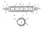
図1は、本発明にかかる紫外線放射蛍光ランプを説明する図であり、(A)発光管の管軸に沿って切断した側断面図、(B)発光管の管軸に対して垂直方向に切断した横断面図である。
紫外線放射蛍光ランプ1を構成する発光管2は、細長いガラス管の両端部に封止部3、3が形成されて放電空間4が形成されており、その内部には発光ガスとしてキセノンガスが封入されている。発光管2の材質としては、波長200nm以下の紫外光に対して透過性を有するものであり、具体的には合成石英ガラスからなる。
内部電極5は発光管2の管軸に沿うように細長い形状の金属で構成され、その形態としては、ロッド状、コイル状、線状、パイプ状のものが適用できる。この内部電極5にはその両端部に金属箔6、6が接続されており、当該金属箔6、6には外方端部に外部リード棒7、7が接続される。
前記金属箔6は、発光管2の封止部3に埋設され、内部電極4の給電用の導通部を構成するとともに、発光管2の気密封止を行うものである。
前記内部電極5は、その軸方向に所定の間隔を設けてサポーター8を備えていて、該サポーター8は、発光管2の内表面側から内部電極5を支持して、これを発光管2のほぼ中心に位置を規定している。
外部電極9は、例えば金属の細線を編んで構成したメッシュ状金属よりなり発光管の外表面に密着するように被せられる。またメッシュ状金属以外にも、導電性ペーストを発光管2の外表面上に塗布形成してもよい。
紫外線放射蛍光ランプ1を構成する発光管2は、細長いガラス管の両端部に封止部3、3が形成されて放電空間4が形成されており、その内部には発光ガスとしてキセノンガスが封入されている。発光管2の材質としては、波長200nm以下の紫外光に対して透過性を有するものであり、具体的には合成石英ガラスからなる。
内部電極5は発光管2の管軸に沿うように細長い形状の金属で構成され、その形態としては、ロッド状、コイル状、線状、パイプ状のものが適用できる。この内部電極5にはその両端部に金属箔6、6が接続されており、当該金属箔6、6には外方端部に外部リード棒7、7が接続される。
前記金属箔6は、発光管2の封止部3に埋設され、内部電極4の給電用の導通部を構成するとともに、発光管2の気密封止を行うものである。
前記内部電極5は、その軸方向に所定の間隔を設けてサポーター8を備えていて、該サポーター8は、発光管2の内表面側から内部電極5を支持して、これを発光管2のほぼ中心に位置を規定している。
外部電極9は、例えば金属の細線を編んで構成したメッシュ状金属よりなり発光管の外表面に密着するように被せられる。またメッシュ状金属以外にも、導電性ペーストを発光管2の外表面上に塗布形成してもよい。
前記発光管2の内表面には、蛍光体と反射体との混合層10が塗布形成されている。
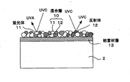
図2に示されるように、混合体層10は、蛍光体11と反射体12との混合体からなる。蛍光体11は、波長200nmの紫外線であるUVCを吸収して波長300nm以上の紫外線であるUVAを放射する特性を有するものであり、例えばセリウム付活マグネシウムバリウムアルミネート、セリウム付活リン酸ガドリニウム・イットリウム、セリウム付活アルミン酸マグネシウム・ランタン、セリウムおよびランタン付活マグネシウムバリウムアルミネートなどを使用することができる。
また、反射体12は、粒径が調製されたアルミナ粉末、シリカ粉末などのセラミック粉末よりなる。反射体としてのセラミック粉末は、単一の材質としてもよいし複数を混合して用いてもよい。
これらの蛍光体粒子11と反射体粒子12を混合したスラリーを発光管2内面に塗布し、これを焼成して混合層10とするものである。
図2に示されるように、混合体層10は、蛍光体11と反射体12との混合体からなる。蛍光体11は、波長200nmの紫外線であるUVCを吸収して波長300nm以上の紫外線であるUVAを放射する特性を有するものであり、例えばセリウム付活マグネシウムバリウムアルミネート、セリウム付活リン酸ガドリニウム・イットリウム、セリウム付活アルミン酸マグネシウム・ランタン、セリウムおよびランタン付活マグネシウムバリウムアルミネートなどを使用することができる。
また、反射体12は、粒径が調製されたアルミナ粉末、シリカ粉末などのセラミック粉末よりなる。反射体としてのセラミック粉末は、単一の材質としてもよいし複数を混合して用いてもよい。
これらの蛍光体粒子11と反射体粒子12を混合したスラリーを発光管2内面に塗布し、これを焼成して混合層10とするものである。
また、図1(B)および図2に示すように、前記混合層10と発光管2との間には、結着材層13が介在している。該結着材層13を構成する結着材は、軟化点が石英ガラスの軟化点よりも低いガラスよりなるガラス粉末を主成分とするものであり、ガラス粉末を分散させたスラリーを発光管内面に塗布、焼成して形成したものである。
このような結着材層13を混合層10と発光管2の間に介在させることにより、紫外線放射蛍光ランプの製造工程において、混合層10を形成する段階で石英ガラスの軟化点近傍まで発光管2を昇温させることなく、混合層10を固着させることができるので、中に含まれる蛍光体11を劣化させることがなく、混合層を形成することができるようになる。
そして、図1(B)に示されるように、かかる混合層10および結着材層13は、その一部が管軸方向に一定の幅で取り除かれたアパーチャ15を備えており、発光管2内で発生した紫外光が該アパーチャ15より出射される。
このような結着材層13を混合層10と発光管2の間に介在させることにより、紫外線放射蛍光ランプの製造工程において、混合層10を形成する段階で石英ガラスの軟化点近傍まで発光管2を昇温させることなく、混合層10を固着させることができるので、中に含まれる蛍光体11を劣化させることがなく、混合層を形成することができるようになる。
そして、図1(B)に示されるように、かかる混合層10および結着材層13は、その一部が管軸方向に一定の幅で取り除かれたアパーチャ15を備えており、発光管2内で発生した紫外光が該アパーチャ15より出射される。
上記構成の紫外線放射蛍光ランプ1において、電極5、9間に高周波高電圧が印加されると、外部電極9が設けられた発光管2の内面と内部電極5との間に半径方向に放電が生起され、放電空間4内に封入されたキセノンガスの発光によりUVC域にある波長172nmの紫外光が出射される。
図2に示されるように、この紫外光(UVC)は、混合層10の蛍光体11に入射してUVAに変換され、反射を繰り返してアパーチャ15からランプ外に出射される。同時に、UVCの一部は混合層10の反射体12によって反射され、この反射が発光管2内で繰り返されてアパーチャ15から出射される。なお、発光管2内で生成されるUVCの一部は、直接アパーチャ15に向かい、外部に出射される。
図2に示されるように、この紫外光(UVC)は、混合層10の蛍光体11に入射してUVAに変換され、反射を繰り返してアパーチャ15からランプ外に出射される。同時に、UVCの一部は混合層10の反射体12によって反射され、この反射が発光管2内で繰り返されてアパーチャ15から出射される。なお、発光管2内で生成されるUVCの一部は、直接アパーチャ15に向かい、外部に出射される。
なお、上記実施例では、発光管2の外表面に外部電極9を設け、内部に内部電極5を設けるものを示したが、発光管2の外周面に対向するように一対の帯状の外部電極を設ける構成であってもよい。この場合には、一対の外部電極はアパーチャ15を避ける位置に設けることは当然である。
以下、このような紫外線放射蛍光ランプの製造方法を図3のフローチャートに基づいて説明する。
A:ガラス管を所定の長さにカットする。
B:蛍光体と、反射体(アルミナ粉末)を、重量比で、1:1で混合し、
この混合粉末に、粉末に対して所定の割合(混合粉末重量に対して
1.5を乗じた体積(cc))で酢酸ブチル+ニトロセルロースの
溶剤を混合し、数日間攪拌を行って、混合スラリーを作製する。
C:発光管に、予め調製しておいたガラス粉末スラリーを塗布し、液を乾
燥させて大気中で焼成し、石英ガラス表面に、結着材としての粉末ガ
ラスを分散させた状態に付着させる(結着材層の形成)。
D:発光管に蛍光体と反射体の混合スラリー液を塗布し、窒素ガスを流し
て乾燥させ、発光管内面に付着させる。その後、アパーチャを形成
する。
なお塗布方法はディッピング法、流し込み法等、適宜の方法で行う。
E:このようにして蛍光体及び反射体の混合粉末を塗布した発光管を大気
中で焼成する(混合層の形成)。
F:その後、混合層および結着材層が形成されていないアパーチャを形成
する。
G:内部電極用のマウントを作製する。かかるマウントは、例えば、内部
電極としてのタングステンコイルと、モリブデン箔と、モリブデン製
のリード棒により構成される。(内部電極にリング状のサポーターを
設けることも可能である。)
H:発光管内部に内部電極を配置したのち発光管を水素処理する。
I:発光管の端部をピンチシールして、封止部を形成する。
J:チップ管から、発光管内部を排気し、キセノンガスを含む放電ガスを
封入する。
K:ステンレス製メッシュで構成した外部電極を、発光管の外表面上に被
覆する。
L:給電用部材(ハーネスなど)を接続して、紫外線放射蛍光ランプが完
成する。
A:ガラス管を所定の長さにカットする。
B:蛍光体と、反射体(アルミナ粉末)を、重量比で、1:1で混合し、
この混合粉末に、粉末に対して所定の割合(混合粉末重量に対して
1.5を乗じた体積(cc))で酢酸ブチル+ニトロセルロースの
溶剤を混合し、数日間攪拌を行って、混合スラリーを作製する。
C:発光管に、予め調製しておいたガラス粉末スラリーを塗布し、液を乾
燥させて大気中で焼成し、石英ガラス表面に、結着材としての粉末ガ
ラスを分散させた状態に付着させる(結着材層の形成)。
D:発光管に蛍光体と反射体の混合スラリー液を塗布し、窒素ガスを流し
て乾燥させ、発光管内面に付着させる。その後、アパーチャを形成
する。
なお塗布方法はディッピング法、流し込み法等、適宜の方法で行う。
E:このようにして蛍光体及び反射体の混合粉末を塗布した発光管を大気
中で焼成する(混合層の形成)。
F:その後、混合層および結着材層が形成されていないアパーチャを形成
する。
G:内部電極用のマウントを作製する。かかるマウントは、例えば、内部
電極としてのタングステンコイルと、モリブデン箔と、モリブデン製
のリード棒により構成される。(内部電極にリング状のサポーターを
設けることも可能である。)
H:発光管内部に内部電極を配置したのち発光管を水素処理する。
I:発光管の端部をピンチシールして、封止部を形成する。
J:チップ管から、発光管内部を排気し、キセノンガスを含む放電ガスを
封入する。
K:ステンレス製メッシュで構成した外部電極を、発光管の外表面上に被
覆する。
L:給電用部材(ハーネスなど)を接続して、紫外線放射蛍光ランプが完
成する。
以下、紫外線放射蛍光ランプの具体的な一数値例を記載する。
・発光管:合成石英ガラス F310(信越石英製)
外径φ16(肉厚t=1)、全長150mm
・封入ガス:キセノンガス(Xe)およびネオンガス(Ne)の混合ガス、
(Xe:Ne混合比 3:7)
封入ガス圧:44kPa(330Torr)
・内部電極:W (素線 φ0.96)
・外部電極:金網(モネル)、線径 φ0.12mm、CPI 8±2
・蛍光体:Ce0.8(Mg0.8,Ba0.1)Al11O18.6、
平均粒子径 5.5μm
・反射体:アルミナ粉末(純度 99.99%、平均粒子径 1μm)
・シール部:モリブデン箔、幅2mm、全長4mm
・発光管:合成石英ガラス F310(信越石英製)
外径φ16(肉厚t=1)、全長150mm
・封入ガス:キセノンガス(Xe)およびネオンガス(Ne)の混合ガス、
(Xe:Ne混合比 3:7)
封入ガス圧:44kPa(330Torr)
・内部電極:W (素線 φ0.96)
・外部電極:金網(モネル)、線径 φ0.12mm、CPI 8±2
・蛍光体:Ce0.8(Mg0.8,Ba0.1)Al11O18.6、
平均粒子径 5.5μm
・反射体:アルミナ粉末(純度 99.99%、平均粒子径 1μm)
・シール部:モリブデン箔、幅2mm、全長4mm
上記ランプを下記の点灯条件で点灯して、ランプから放射されるUVCの放射強度とUVAの放射強度をそれぞれ測定した。
<点灯条件>
・高周波点灯インバーター 70kHz、矩形波、1700V0-p
<放射照度計>
・UVC用(172nm測定):UIT-250A + VUV-S172
・UVA用(340nm測定):UVR-300 + UD360
・測定条件:ランプの発光管表面から受光器面までの距離7mm
<点灯条件>
・高周波点灯インバーター 70kHz、矩形波、1700V0-p
<放射照度計>
・UVC用(172nm測定):UIT-250A + VUV-S172
・UVA用(340nm測定):UVR-300 + UD360
・測定条件:ランプの発光管表面から受光器面までの距離7mm
なお、発光スペクトルを測定する場合には、通常は、発光波長領域において感度を有する単一の分光器を用いて行うが、本発明にかかる紫外線放射蛍光ランプにおいては、UVC領域の真空紫外光である172nmと、UVA領域の340nmピークの発光を同時に行うものであるため、このような範囲を網羅する感度領域をもつ分光器が市販で存在しないので、両波長領域を一度に測定することができない。
このため、便宜的に感度領域が異なる2つの放射照度計を用いてUVA、UVCのそれぞれの波長帯で放射強度を測定した。具体的には、UVAの波長200~450nm領域の紫外線については分光器 USR-40Dを、UVCの150~200nm領域の真空紫外領域については、ANDOR DU420-UV-FKを用いてそれぞれ個別に測定した。
このため、便宜的に感度領域が異なる2つの放射照度計を用いてUVA、UVCのそれぞれの波長帯で放射強度を測定した。具体的には、UVAの波長200~450nm領域の紫外線については分光器 USR-40Dを、UVCの150~200nm領域の真空紫外領域については、ANDOR DU420-UV-FKを用いてそれぞれ個別に測定した。
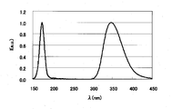
その測定結果を示す波長150nm~波長450nmの範囲の発光スペクトル図を図4に示す。
なお、同図は、各分光器より得られたUVC及びUVAの発光スペクトルについて、理解を得やすくするために、各発光ピークの値を1に換算して同一グラフ上に表したものである。
図4で明らかなように、波長172nmのUVCと、ピーク波長340nmのUVAとが、同時に発光されていることが分かる。
なお、同図は、各分光器より得られたUVC及びUVAの発光スペクトルについて、理解を得やすくするために、各発光ピークの値を1に換算して同一グラフ上に表したものである。
図4で明らかなように、波長172nmのUVCと、ピーク波長340nmのUVAとが、同時に発光されていることが分かる。
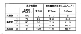
続いて、上記実施例の仕様において、混合層に含まれる蛍光体と反射体(アルミナ粉末)の混合比率を変化させてランプを作製し、これらの混合比率を変えた場合の発光強度の違いについて調査を行った。
但し、ランプ使用および測定仕様は以下の通りである。
発光管外径φ16(t=1.0の場合)
点灯条件:高周波点灯インバーター 70kHz、矩形波、1700V
照度計:<172nm測定>UIT-250A + VUV-S172
<340nm測定>UVR-300 + UD360
ランプ発光管表面-受光器面 7mm
但し、ランプ使用および測定仕様は以下の通りである。
発光管外径φ16(t=1.0の場合)
点灯条件:高周波点灯インバーター 70kHz、矩形波、1700V
照度計:<172nm測定>UIT-250A + VUV-S172
<340nm測定>UVR-300 + UD360
ランプ発光管表面-受光器面 7mm
その結果が図5の表に表されている。
混合層を蛍光体のみで構成した比較例2においては、アパーチャからは専ら蛍光体で変換された波長340nmの紫外線が放射されるとともに、発光管内で生成した波長172nmの真空紫外光が、発光管(合成石英ガラス)を透過して直接アパーチャから放射される。しかしながらその光出力はごく僅かである。
一方、蛍光体を設けずに反射体のみを設けた比較例1では、当然ながら、真空紫外光172nmのみが放射される。
これに対して、反射体と蛍光体とを混合させた本発明ランプ1~3においては、反射体(アルミナ)の混合比率が、重量比で25%~75%の間では、波長172nm及び波長340nmの両方の紫外光を放射することが確認された。
混合層を蛍光体のみで構成した比較例2においては、アパーチャからは専ら蛍光体で変換された波長340nmの紫外線が放射されるとともに、発光管内で生成した波長172nmの真空紫外光が、発光管(合成石英ガラス)を透過して直接アパーチャから放射される。しかしながらその光出力はごく僅かである。
一方、蛍光体を設けずに反射体のみを設けた比較例1では、当然ながら、真空紫外光172nmのみが放射される。
これに対して、反射体と蛍光体とを混合させた本発明ランプ1~3においては、反射体(アルミナ)の混合比率が、重量比で25%~75%の間では、波長172nm及び波長340nmの両方の紫外光を放射することが確認された。
以上のように、本発明の紫外線放射蛍光ランプでは、発光管内にUVCをUVAに変換する蛍光体を備え、前記発光管内面に、前記蛍光体とUVC領域の光に対して反射特性を有する反射体とを混合した混合層が形成されてなり、当該混合層には、アパーチャが形成されていることにより、発光管内でのエキシマ発光により生成されたUVCが、その一部が混合層中の蛍光体によりUVAに変換されてアパーチャから放射されるとともに、他の一部が混合層中の反射体によりそのまま反射されてアパーチャから放射されるので、ひとつのランプからUVCとUVAとを同時に放射できる。
そのため、特にデンタルインプラントの人工歯根の線状煮適用した場合、ひとつのランプで、人工歯根材料であるチタンに対するUVAによる触媒作用と、UVCによるオゾン作用が効果的に行われるという効果を奏するものである。
そのため、特にデンタルインプラントの人工歯根の線状煮適用した場合、ひとつのランプで、人工歯根材料であるチタンに対するUVAによる触媒作用と、UVCによるオゾン作用が効果的に行われるという効果を奏するものである。
1 紫外線放射蛍光ランプ
2 発光管(石英ガラス)
3 封止部
4 放電空間
5 内部電極
6 金属箔
7 外部リード棒
8 サポーター
10 混合層
11 蛍光体
12 反射体
13 結着材層
15 アパーチャ
2 発光管(石英ガラス)
3 封止部
4 放電空間
5 内部電極
6 金属箔
7 外部リード棒
8 サポーター
10 混合層
11 蛍光体
12 反射体
13 結着材層
15 アパーチャ
Claims (2)
- 石英ガラスからなる発光管を有し、UVCをUVAに変換する蛍光体を備えた紫外線放射蛍光ランプにおいて、
前記発光管内面に、前記蛍光体とUVC領域の光に対して反射特性を有する反射体とを混合した混合層が形成されてなり、
当該混合層には、アパーチャが形成されていることを特徴とする紫外線放射蛍光ランプ。 - 前記発光管内面と前記混合層の間に、石英ガラスよりも軟化点温度が低い物質からなる結着材層が形成されていることを特徴とする請求項1記載の紫外線放射蛍光ランプ。
Priority Applications (1)
| Application Number | Priority Date | Filing Date | Title |
|---|---|---|---|
| CN201380016419.XA CN104205288B (zh) | 2012-04-04 | 2013-02-28 | 紫外线放射荧光灯 |
Applications Claiming Priority (2)
| Application Number | Priority Date | Filing Date | Title |
|---|---|---|---|
| JP2012-085679 | 2012-04-04 | ||
| JP2012085679A JP5861989B2 (ja) | 2012-04-04 | 2012-04-04 | 紫外線放射蛍光ランプ |
Publications (1)
| Publication Number | Publication Date |
|---|---|
| WO2013150846A1 true WO2013150846A1 (ja) | 2013-10-10 |
Family
ID=49300344
Family Applications (1)
| Application Number | Title | Priority Date | Filing Date |
|---|---|---|---|
| PCT/JP2013/055351 Ceased WO2013150846A1 (ja) | 2012-04-04 | 2013-02-28 | 紫外線放射蛍光ランプ |
Country Status (3)
| Country | Link |
|---|---|
| JP (1) | JP5861989B2 (ja) |
| CN (1) | CN104205288B (ja) |
| WO (1) | WO2013150846A1 (ja) |
Cited By (2)
| Publication number | Priority date | Publication date | Assignee | Title |
|---|---|---|---|---|
| JP2021125437A (ja) * | 2020-02-10 | 2021-08-30 | 東芝ライテック株式会社 | バリア放電ランプモジュール、バリア放電ランプ、および紫外線照射装置 |
| JP7509356B2 (ja) | 2020-07-22 | 2024-07-02 | 国立大学法人福井大学 | 放電ランプ、光源装置、放電ランプまたは光源装置用合成シリカガラス管の製造方法および発光部材 |
Families Citing this family (6)
| Publication number | Priority date | Publication date | Assignee | Title |
|---|---|---|---|---|
| CN106783526A (zh) * | 2016-12-26 | 2017-05-31 | 上海开若纳科技有限公司 | 一种大尺寸准分子灯 |
| KR101904017B1 (ko) * | 2017-08-29 | 2018-10-04 | 주식회사 디오 | 치아 임플란트의 표면처리용 자외선 조사장치 |
| US20210245100A1 (en) * | 2018-05-22 | 2021-08-12 | Ushio Denki Kabushiki Kaisha | Light transmissive material and lamp, and gas treatment device and gas treatment method |
| CN110055534A (zh) * | 2019-04-19 | 2019-07-26 | 江苏美安医药股份有限公司 | 一种种植牙表面处理工艺 |
| CN111513880B (zh) * | 2020-05-08 | 2021-07-27 | 桂林市啄木鸟医疗器械有限公司 | 一种种植体活化方法及活化种植体 |
| EP4030163B1 (en) | 2021-01-19 | 2025-12-31 | ATLAS Material Testing Technology GmbH | FLUORESCENT MATERIAL AS A SOURCE OF RADIATION IN AN ARTIFICIAL WEATHERPROOFING DEVICE |
Citations (7)
| Publication number | Priority date | Publication date | Assignee | Title |
|---|---|---|---|---|
| JPH02172153A (ja) * | 1988-12-26 | 1990-07-03 | Hitachi Ltd | 反射膜付蛍光ランプ |
| JPH07320693A (ja) * | 1994-03-31 | 1995-12-08 | Hitachi Ltd | 蛍光ランプ |
| JP2004055403A (ja) * | 2002-07-22 | 2004-02-19 | Toshiba Lighting & Technology Corp | 蛍光ランプおよびリサイクル蛍光ランプの製造方法 |
| JP2007173090A (ja) * | 2005-12-22 | 2007-07-05 | Ushio Inc | 紫外線光源装置 |
| JP2009123406A (ja) * | 2007-11-13 | 2009-06-04 | Ushio Inc | 外部電極型希ガス蛍光ランプ |
| JP2010153054A (ja) * | 2008-12-24 | 2010-07-08 | Ushio Inc | 蛍光ランプ |
| JP2011070780A (ja) * | 2009-09-24 | 2011-04-07 | Ushio Inc | 蛍光ランプ |
-
2012
- 2012-04-04 JP JP2012085679A patent/JP5861989B2/ja not_active Expired - Fee Related
-
2013
- 2013-02-28 CN CN201380016419.XA patent/CN104205288B/zh not_active Expired - Fee Related
- 2013-02-28 WO PCT/JP2013/055351 patent/WO2013150846A1/ja not_active Ceased
Patent Citations (7)
| Publication number | Priority date | Publication date | Assignee | Title |
|---|---|---|---|---|
| JPH02172153A (ja) * | 1988-12-26 | 1990-07-03 | Hitachi Ltd | 反射膜付蛍光ランプ |
| JPH07320693A (ja) * | 1994-03-31 | 1995-12-08 | Hitachi Ltd | 蛍光ランプ |
| JP2004055403A (ja) * | 2002-07-22 | 2004-02-19 | Toshiba Lighting & Technology Corp | 蛍光ランプおよびリサイクル蛍光ランプの製造方法 |
| JP2007173090A (ja) * | 2005-12-22 | 2007-07-05 | Ushio Inc | 紫外線光源装置 |
| JP2009123406A (ja) * | 2007-11-13 | 2009-06-04 | Ushio Inc | 外部電極型希ガス蛍光ランプ |
| JP2010153054A (ja) * | 2008-12-24 | 2010-07-08 | Ushio Inc | 蛍光ランプ |
| JP2011070780A (ja) * | 2009-09-24 | 2011-04-07 | Ushio Inc | 蛍光ランプ |
Cited By (2)
| Publication number | Priority date | Publication date | Assignee | Title |
|---|---|---|---|---|
| JP2021125437A (ja) * | 2020-02-10 | 2021-08-30 | 東芝ライテック株式会社 | バリア放電ランプモジュール、バリア放電ランプ、および紫外線照射装置 |
| JP7509356B2 (ja) | 2020-07-22 | 2024-07-02 | 国立大学法人福井大学 | 放電ランプ、光源装置、放電ランプまたは光源装置用合成シリカガラス管の製造方法および発光部材 |
Also Published As
| Publication number | Publication date |
|---|---|
| CN104205288B (zh) | 2016-12-07 |
| JP5861989B2 (ja) | 2016-02-16 |
| JP2013218793A (ja) | 2013-10-24 |
| CN104205288A (zh) | 2014-12-10 |
Similar Documents
| Publication | Publication Date | Title |
|---|---|---|
| JP5861989B2 (ja) | 紫外線放射蛍光ランプ | |
| JP4647745B2 (ja) | 水殺菌装置 | |
| JP2005519438A (ja) | 紫外放射発生装置 | |
| WO2014148325A1 (ja) | 蛍光エキシマランプおよび流体処理装置 | |
| CN102169801B (zh) | 荧光灯 | |
| CN1333549A (zh) | 荧光灯和具有改进了发光效率的高强度放电灯 | |
| TW201009883A (en) | Fluorescent lamp | |
| CN102034676B (zh) | 荧光灯 | |
| KR101373943B1 (ko) | 형광 램프 | |
| JP5850539B2 (ja) | 放電ランプ、使用方法及びシステム | |
| JP5397455B2 (ja) | 希ガス蛍光ランプ | |
| TW201225152A (en) | Fluorescent lamp | |
| TWI493596B (zh) | Fluorescent light | |
| CN102709149B (zh) | 荧光灯及其制造方法 | |
| JP2012064381A (ja) | 蛍光ランプ | |
| JP5682306B2 (ja) | 光照射ユニット | |
| CN102725819B (zh) | 用于美容皮肤护理的电子高压放电灯 | |
| KR20110030327A (ko) | 자외선 조사 방법 및 메탈할라이드 램프 | |
| TW200952029A (en) | Ultraviolet discharge lamp | |
| JP2014127245A (ja) | 蛍光ランプ |
Legal Events
| Date | Code | Title | Description |
|---|---|---|---|
| 121 | Ep: the epo has been informed by wipo that ep was designated in this application |
Ref document number: 13771878 Country of ref document: EP Kind code of ref document: A1 |
|
| NENP | Non-entry into the national phase |
Ref country code: DE |
|
| 122 | Ep: pct application non-entry in european phase |
Ref document number: 13771878 Country of ref document: EP Kind code of ref document: A1 |