WO2013150689A1 - 動き画像領域判定装置またはその方法 - Google Patents
動き画像領域判定装置またはその方法 Download PDFInfo
- Publication number
- WO2013150689A1 WO2013150689A1 PCT/JP2012/082992 JP2012082992W WO2013150689A1 WO 2013150689 A1 WO2013150689 A1 WO 2013150689A1 JP 2012082992 W JP2012082992 W JP 2012082992W WO 2013150689 A1 WO2013150689 A1 WO 2013150689A1
- Authority
- WO
- WIPO (PCT)
- Prior art keywords
- motion
- block
- time
- rectangular
- frame
- Prior art date
- Legal status (The legal status is an assumption and is not a legal conclusion. Google has not performed a legal analysis and makes no representation as to the accuracy of the status listed.)
- Ceased
Links
Images


Classifications
-
- H—ELECTRICITY
- H04—ELECTRIC COMMUNICATION TECHNIQUE
- H04N—PICTORIAL COMMUNICATION, e.g. TELEVISION
- H04N5/00—Details of television systems
- H04N5/14—Picture signal circuitry for video frequency region
- H04N5/144—Movement detection
-
- G—PHYSICS
- G06—COMPUTING OR CALCULATING; COUNTING
- G06T—IMAGE DATA PROCESSING OR GENERATION, IN GENERAL
- G06T7/00—Image analysis
- G06T7/20—Analysis of motion
- G06T7/215—Motion-based segmentation
-
- G—PHYSICS
- G06—COMPUTING OR CALCULATING; COUNTING
- G06T—IMAGE DATA PROCESSING OR GENERATION, IN GENERAL
- G06T2207/00—Indexing scheme for image analysis or image enhancement
- G06T2207/20—Special algorithmic details
- G06T2207/20021—Dividing image into blocks, subimages or windows
-
- H—ELECTRICITY
- H04—ELECTRIC COMMUNICATION TECHNIQUE
- H04N—PICTORIAL COMMUNICATION, e.g. TELEVISION
- H04N7/00—Television systems
- H04N7/01—Conversion of standards, e.g. involving analogue television standards or digital television standards processed at pixel level
- H04N7/0117—Conversion of standards, e.g. involving analogue television standards or digital television standards processed at pixel level involving conversion of the spatial resolution of the incoming video signal
-
- H—ELECTRICITY
- H04—ELECTRIC COMMUNICATION TECHNIQUE
- H04N—PICTORIAL COMMUNICATION, e.g. TELEVISION
- H04N7/00—Television systems
- H04N7/01—Conversion of standards, e.g. involving analogue television standards or digital television standards processed at pixel level
- H04N7/0135—Conversion of standards, e.g. involving analogue television standards or digital television standards processed at pixel level involving interpolation processes
- H04N7/0137—Conversion of standards, e.g. involving analogue television standards or digital television standards processed at pixel level involving interpolation processes dependent on presence/absence of motion, e.g. of motion zones
Definitions
- the present invention relates to a method for determining a moving image area, and more particularly to determination of a rectangular moving image area.
- Patent Document 1 discloses motion detection in units of blocks. Specifically, the gradation values of the same pixel in the previous and subsequent frames are compared, and if the gradation values are different, it is determined as a moving pixel, and the ratio of the number of moving pixels is calculated for each block, which is larger than the threshold value. In this case, it is determined that the block is a moving image block.
- An object of the present invention is to solve the above problems and provide a determination method or apparatus for determining a rectangular motion image area with a simple configuration.
- the rectangular motion image region determination method is based on the difference between the frame at time t and the frame at time t + n for the rectangular motion image region displayed in a part of the display region.
- a rectangular motion image region determination method for determining a boundary of a rectangular motion image region whose outline is a rectangle, and when the rectangular motion image region in a frame at time t is determined, the boundary coordinates are retained and the boundary of the frame at time t Without using an image, for the frame at time t + m, it is determined whether there is a frame at the position of the boundary coordinate at time t. If there is a frame, the area specified by the boundary coordinate at time t is It is determined that it is a motion region in the frame at time t + n, where n ⁇ m.
- the region specified by the boundary coordinates at time t can be determined as the motion region in the frame at time t + n.
- the display area includes pixels arranged in rows and columns, and the rectangular moving image area in the frame at time t is obtained by the following steps: ,It is determined.
- a motion unit block determination step for dividing the display area into unit blocks each including a predetermined number of pixels and determining whether each unit block is a motion unit block in which motion exists; , A set of unit blocks belonging to the same column as each unit block located in the uppermost row is defined as a column block, and when at least one motion unit block exists in each column block, that column block is defined as a motion column block
- a motion sequence block determination step to determine, a set of unit blocks belonging to the same row as each unit block located in the leftmost stage among the unit blocks is defined as a row block, and at least one motion unit block is included in each row block If there is a motion row block decision, the row block is determined as a motion row block. Step, the motion row block and the first rectangular motion image area determining step of determining a rectangular region specified by the
- the rectangular area specified by the unit block belonging to both the motion row block and the motion sequence block can be determined as the rectangular motion image area.
- the first rectangular moving image region determining step includes the step of: Defining the outer row block straight line of the set row block, and when there is an adjacent motion row block or more of the motion column blocks, the outer row block straight line of the set row block of these row blocks is defined, A rectangular area surrounded by the outline row block straight line and the outline column block straight line is determined as a rectangular motion image area. Therefore, the rectangular motion image area can be determined.
- the row direction The pixels constituting the edge and the column direction edge are extracted, and the boundary of the rectangular motion image region is determined based on the total number of pixels constituting the row direction edge for each row and the total number of pixels constituting the column direction edge for each column. . Therefore, it is possible to determine a rectangular motion image area with high accuracy.
- the time image is used without using the frame image at time t.
- the frame at t + b it is determined whether or not there is a frame at the position of the boundary coordinate at time t. If there is a frame, the region specified by the boundary coordinate at time t is If it is determined to be a motion area and a motion area is detected from an image of a frame at time t and time t + n, a rectangle in the frame at time t + n is determined from the frame at time t and time t + n.
- the moving image area When the moving image area is determined, it is determined whether or not the moving image area is included in the area specified by the boundary coordinates at the time t, and if included, the time t + is used without using the frame image at the time t.
- Boundary locus at time t for frame b It is determined whether there is a frame in position, if there is a frame may be determined to be a motion area in the time frame at time t + n the region specified by the boundary coordinates t,
- b and n are integers satisfying n ⁇ b ⁇ 1.
- the region specified by the boundary coordinates at time t can be determined as the motion region in the frame at time t + n for the frame at time t + b.
- the frame determination can be performed when the inside is repeatedly detected.
- a rectangular motion image region displayed in a part of the display region is based on a difference between a frame at time t and a frame at time t + n.
- a rectangular motion image region determination device for determining a boundary of a rectangular motion image region having a rectangular outer shape, a unit for determining a rectangular motion image region in a frame at time t, and a boundary coordinate holding unit for holding the determined boundary coordinate
- the frame determining means for determining whether or not there is a frame at the position of the boundary coordinates at the time t for the frame at the time t + m without using the image of the frame at the time t.
- a motion region determining means for determining that the region specified by the boundary coordinates at time t is a motion region in the frame at time t + n, where n ⁇ m.
- the region specified by the boundary coordinates at time t can be determined as the motion region in the frame at time t + n.
- the rectangular motion image region displayed in a part of the display region is based on the difference between the image of the frame at time t and the frame at time t + n.
- the region specified by the boundary coordinates at time t can be determined as the motion region in the frame at time t + m without using the image of the frame at time t + n. .
- pixel value includes not only luminance values but also numerical values for specifying image information such as RGB values.
- rectangular motion image area refers to a rectangular area that has different pixel values between a plurality of frames and constitutes a motion image area.
- “Column block” refers to a set of unit blocks belonging to the same column as each unit block located at the top of the unit blocks. In the present embodiment, one unit block located in the uppermost stage is identified and a column block is determined. As a result, if one unit block located in the uppermost stage is included, a unit block other than the uppermost stage is included. You may make it identify from a line. “Row block” refers to a set of unit blocks belonging to the same row as the unit blocks located in the leftmost stage among the unit blocks. As a result, the specific method is not particularly limited as long as it includes one unit block located in the leftmost stage.
- the “first rectangular moving image region determining step” and the “second rectangular moving image region determining step” are respectively performed by a moving image region determining process (step S7 in FIG. 3) and a boundary determining process (step S9 in FIG. 3). Applicable.
- the “column direction” refers to the direction in which each row is arranged, and in the embodiment refers to the ⁇ direction.
- “Row direction edge” refers to an edge in a direction parallel to the row direction, and “Column direction edge” refers to an edge in a direction parallel to the column direction.
- the “inclusive” means that one or two corners of the past motion area are hidden as well as all four sides are inside the past motion area. Including cases.
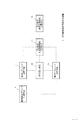
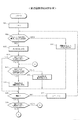
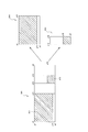
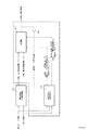
- FIG. 3 is a functional block diagram of the rectangular motion image region determination device 1.
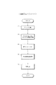
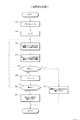
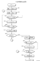
- FIG. It is an example of a hardware structure at the time of comprising the rectangular moving image area determination apparatus 1 using CPU. It is the whole flowchart.
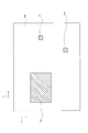
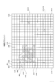
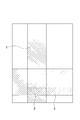
- a display area 100 in which motion image areas 110 to 112 exist is shown.
- FIG. 1 shows a functional block diagram of a rectangular motion image region determination device 1 according to an embodiment of the present invention.
- the rectangular motion image region determination device 1 is a device that determines a rectangular motion image region to be displayed in a part of a display region in which pixels are arranged in a matrix in the row direction and the column direction. 5, a motion sequence block determination unit 7, a motion row block determination unit 9, a first rectangular motion image region determination unit 11, a repetition unit 13, and a second rectangular motion image region determination unit 14.
- the motion unit block determination means 5 divides the display area into unit blocks each including a predetermined number of pixels, and determines that each unit block is a motion unit block in which motion exists.
- the motion column block determining means 7 defines a set of unit blocks belonging to the same column as each unit block located at the top of the unit blocks as a column block, and at least one motion unit block is included in each column block. If it exists, the column block is determined as a motion column block.
- the motion row block determining means 9 defines a set of unit blocks belonging to the same row as each unit block located in the leftmost stage among the unit blocks as a row block, and at least one motion unit block is included in each row block. If it exists, the row block is determined as a motion row block.
- the first rectangular motion image area determining means 11 determines a rectangular area specified by a unit block belonging to both the motion row block and the motion sequence block as a rectangular motion image area.
- the repeater 13 repeatedly executes the processing by the motion sequence block determiner 7, the motion row block determiner 9, and the rectangular motion image region determiner 11 for the rectangular motion image region determined by the first rectangular motion image region determiner 11.
- Let The second rectangular motion image area determining means 14 is configured to determine the rectangular motion image area based on each pixel in the unit blocks constituting the outer four sides of the unit blocks constituting the rectangular motion image area. An area defined by an edge inside is defined as the rectangular motion image area.
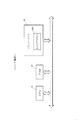
- FIG. 2 shows a hardware configuration of the rectangular motion image area determination device 1.
- the rectangular motion image area determination device 1 includes a CPU 23, a RAM 25, and a flash memory 26.
- the flash memory 26 stores a program 26p.
- the program 26p performs a rectangular motion image region determination process as will be described later.
- the RAM 25 stores calculation results and the like.
- the frame memory 27 holds image data for one screen.
- the CPU 23 determines whether or not it is a moving image area composed of pixels with motion based on the pixel values constituting the display area stored in the memory 27, and stores the result in the RAM 25.
- pixels are arranged in a matrix in the row direction ⁇ and the column direction ⁇ .
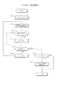
- CPU 23 performs block division (step S1 in FIG. 3).
- 32 * 32 pixels are used as one block, and the display area 100 shown in FIG. 4 is divided into a plurality of blocks in a matrix.
- the block is divided into n + 1 blocks in the ⁇ direction and m + 1 blocks in the ⁇ direction.
- CPU 23 determines representative values for all blocks (step S3 in FIG. 3).
- the representative value instead of using the average value of the pixel values in one block, the top pixel value, and the value as it is, a hash value such as CRC may be used as the representative value.
- the average value can be expressed in 18-bit length in a 32 * 32 * 8-bit image, but the upper and lower 10 bits may be rounded down and only the middle 8 bits may be used.
- (n + 1) * (m + 1) block representative values are stored in the RAM 25.
- CPU 23 determines a motion block among (n + 1) * (m + 1) blocks (step S5).
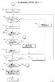
- the motion block determination process will be described with reference to FIG.
- CPU 23 initializes processing block numbers i and j (steps S11 and S13 in FIG. 5).
- the block (0, 0) is compared with the representative value of the previous frame (step S15).
- the representative values at time t and time t ⁇ 1 are compared.
- the CPU 23 determines whether or not the difference between the representative values exceeds the threshold value thb (step S17). If the difference between the representative values exceeds the threshold value thb, it is determined as a motion block (step S19). On the other hand, if the difference between the representative values does not exceed the threshold thb, it is determined as a non-motion block (step S21).
- step S23 if the processing block number j is final, the process proceeds to step S27, and the CPU 23 determines whether or not the processing block number i is final. In this case, since it is not final, the processing block number i is incremented (step S29), and step S13 and subsequent steps are repeated. If the process block number i is the last in step S27, the process is terminated.
- a motion block is determined for (n + 1) * (m + 1) blocks.
- blocks (4, 2), (4, 3), (4, 4)... are determined as motion blocks.
- the CPU 23 performs a motion image area determination process (step S7 in FIG. 3). Details of the moving image region determination processing will be described with reference to FIGS.
- the CPU 23 determines that the column is a non-motion column (step S37).
- the CPU 23 determines whether there is a temporary motion sequence that has been added and stored (step S39). If there is, the CPU 23 determines whether the adjacent set has a width that exceeds the threshold thw (step S39).
- the threshold thw is set to 2 blocks or more. In this case, since the temporary motion sequence stored in addition exists from blocks (0, 2) to (0, 8), the threshold value thw is exceeded, so the temporary motion sequence is set as a motion sequence (step S45).
- the CPU 23 determines whether or not the processing block number j is final (step S46).
- the CPU 23 determines that the column is a non-motion column (step S37). The CPU 23 determines whether or not the detected temporary motion sequence exists (step S39). In this case, since it does not exist, the CPU 23 determines whether or not the processing block number j is final (step S46).
- the CPU 23 determines that the column is a non-motion column (step S37). The CPU 23 determines whether or not the detected temporary motion sequence exists (step S39). If there is, the CPU 23 determines whether or not the adjacent set has a width exceeding the threshold thw (step S41). ). In the present embodiment, since the threshold thw is 2 blocks or more, the width of the temporary motion sequence does not exceed the threshold thw, so the temporary motion sequence is set as a non-motion sequence (step S43). Thereby, it is possible to prevent an image area such as a mouse from being erroneously recognized as a moving image area.
- step S49 it is determined whether or not the provisional motion sequence that has been added and stored exists, and if it exists, the processing from step S41 is executed.
- Fig. 8 shows the motion sequence after detection.
- the region 121 is determined as a motion sequence.
- the regions 122 and 123 to which the motion blocks (6, n-3) and (m-3, n-6) belong do not have a width equal to or greater than the threshold thw in the direction of the arrow ⁇ . Is not determined.
- the CPU 23 initializes the processing block number i (step S51 in FIG. 9).
- the CPU 23 determines whether or not there is at least one motion block in the row of the block (0, 0) (step S53). In this case, as shown in FIG. 6, since there is no motion block in the block (0,0) and its horizontal blocks (0,1) to (0, n), such a row is a non-motion row. Is determined (step S57).
- step S57 The CPU 23 determines whether there is a motion row that has been added and stored (step S59). In this case, since there is a motion row that has been added and stored, it is determined whether or not the set has a width that exceeds the threshold thw (step S61).
- the threshold thw is set to 2 blocks or more. In this case, since there are detected motion rows from block (4,0) to (8,0), the threshold thw is exceeded, so the temporary motion row is set as a motion row (step S65).
- step S69 is the same as that of step S49, description thereof is omitted.
- Fig. 10 shows the motion line after detection.
- the area 131 is determined as a movement line.
- the motion block (6, n-3) belongs to the region 131.
- the region 132 to which the motion block (m ⁇ 3, n ⁇ 6) belongs does not have a width equal to or larger than the threshold thw in the arrow ⁇ direction, and is not determined as a motion row.
- the CPU 23 determines a block belonging to both the motion sequence and the motion row as a motion image area (step S70 in FIG. 9).
- a block belonging to an area 140 where the area 121 and the area 131 shown in FIG. 11 overlap is determined as a moving image area.
- the block (4,5) and the like are determined as motion image regions. . In this way, it is possible to prevent spillage in relation to the surrounding blocks.
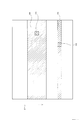
- step S9 in FIG. 3 the boundary of the motion image area in the block composed of 32 * 32 pixels is obtained.
- step S9 the boundary 150 of the motion image area in units of one pixel can be obtained. Details of step S9 will be described with reference to FIG.
- step S80 extracts the upper block (step S80 in FIG. 12). In this case, a total of seven blocks (4,2) to (4,8) shown in FIG. 13 are extracted.
- the CPU 23 initializes the processing row number P (step S81), extracts all the pixels in the P row of the extracted block, and calculates the representative value (step S83). In this case, 32 pixels in the 0th row of the block (4,2), 32 pixels... And 7 * 32 pixels in the 0th row of the block (4,3) are extracted, and their representative values are calculated. In this embodiment, the representative value is the average value of the extracted pixels.
- the CPU 23 extracts all the pixels in the processing row number P + 1 row of the extracted block and calculates the representative value (step S85).
- 32 pixels in the first row of the block (4, 2), 32 pixels... And 7 * 32 pixels in the first row of the block (4, 3) are extracted, and their representative values are calculated.
- step S87 determines whether or not the representative value obtained in step S83 is different from the representative value obtained in step S85 (step S87). If both are different in step S87, it is determined that the row of the pixel (P, 0) is a boundary (step S93). If they are not different in step S87, the process row number P is incremented (step S89), and step S83 and subsequent steps are repeated until the final pixel of the extraction block (32 pixels in this case) is reached (step S91). If both are not different in step S87 even for the last pixel, it is determined that the end of the extracted block is a boundary (step S95).
- FIG. 12 illustrates the case where the boundary of one pixel unit in the upper block is extracted, but the same applies to the lower block.
- pixels for one column are extracted in the vertical direction, and the representative values may be compared with adjacent columns.
- This device can automatically detect the motion image area.
- the determination can also be detected in several frames. Therefore, even if the moving image area itself dynamically changes on the monitor, the moving image area can be detected almost in real time.
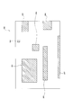
- step S7 in FIG. 3 is further repeated for the determined motion image area, so that the motion image area is detected even when there are a plurality of motion image areas 201 to 207 as shown in FIG. be able to.
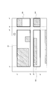
- step S7 in FIG. 3 Once the process of step S7 in FIG. 3 is performed, motion image areas 301 to 304 as shown in FIG. 15 are determined.
- the region 207 is not detected as a motion image region because it does not have a width equal to or greater than the threshold thw.
- the motion region 301 originally includes a region that is not a motion image region.
- the CPU 23 regards the areas 301 to 304 as the entire image area, and detects the motion image area again. Thereby, for example, in the case of the area 301, the area 311 defined by the block coordinates (y1, x1) (y3, x11) and the area 312 defined by the block coordinates (y1, x12) (y3, x13) are detected. Is done. The same applies to the other areas 302 to 304.
- the region 311 is regarded as the entire image region, and the motion image region is detected again. Thereby, an area defined by the block coordinates (y1, x1) (y11, x11) is detected. The same applies to the region 312.
- Such repeated detection may be performed until it can no longer be divided, or the upper limit number of repeated detections may be determined in advance.
- CPU23 extracts the block except the edge part among upper blocks (Step S100 of Drawing 17). In this case, a total of five blocks (4,3) to (4,7) shown in FIG. 13 are extracted. The reason for removing the end portion in this way is that there is a possibility that some of the blocks at both end portions do not have an edge. However, this end block may also be adopted.
- the CPU 23 initializes the processing row number r and the processing pixel number g (steps S101 and S102 in FIG. 17), and determines whether the g-th pixel of the extracted block of the row number “0” is a horizontal edge pixel (row direction edge). It is determined whether or not (step S103). Whether or not the pixel is a horizontal edge pixel may be determined based on a luminance difference from an adjacent pixel. In the present embodiment, a filter and an arithmetic expression as shown in FIG. 18A are employed.
- the CPU 23 determines that the Pth pixel is a horizontal edge pixel, the CPU 23 increments the total number Et (step S105 in FIG. 17). The CPU 23 determines whether or not all lines have been completed (step S107). If not, the processing pixel number g is incremented (step S109), and steps S103 to S107 are repeated.
- the CPU 23 determines whether or not the total number Et of horizontal edges in the line is larger than a preset threshold value ths (step S111). This is to eliminate the horizontal edge pixels as contours in the moving image area.
- the CPU 23 sets it as a boundary (step S113). As a result, a boundary where the set of horizontal edges exceeds the threshold ths can be obtained.
- the threshold ths may be a fixed threshold, or a ratio may be set in advance and calculated according to the size of the detected area (number of blocks).
- step S111 if “NO”, the CPU 23 determines whether or not all lines have been completed (step S113). If all lines have not been completed, the CPU 23 increments the process line number r and repeats steps S102 to S111.
- the boundary can be determined on a pixel-by-pixel basis.
- vertical edges may be detected in the same manner using the filters and arithmetic expressions shown in FIG. 18B for the unit blocks located at the rightmost and leftmost stages.
- boundary determination is performed based on the total number of vertical edges and horizontal edges. Therefore, even a moving image region on a messy background can be detected. In addition, detection accuracy is improved and shaking of the moving image area is reduced.
- the pixels of all the blocks except for the end portion among the blocks obtained in FIG. 11 are adopted, but it may be determined by a part thereof.
- the comparison with the threshold value ths is a total of one line.
- the boundary is a boundary.
- edge images may exist even in natural images. Therefore, edges that are not continuous over a certain number may be removed from the calculation of the total number.
- the present invention is applied to the case where the rectangular area is determined and the boundary of one pixel unit for the block on the outer periphery thereof is determined.
- the present invention is applicable to general motion estimation and other fields.
- a boundary of a plurality of pixel units (for example, 2 * 2 pixel units) may be obtained instead of one pixel unit.
- the boundary is determined by extracting edge pixels. However, for each pixel in the target block, it can be determined whether there is a motion vector between different frames, and a motion vector can be detected. You may make it judge that the boundary of a pixel and the pixel which cannot be detected is a boundary.
- the boundaries of each frame may be stored in sequence, and if the boundary cannot be detected in a certain frame, the accumulated boundary may be adopted.
- the number of frames to be accumulated is set to ten or more frames.
- the CPU 23 initializes the target row number Q and the number of matching rows k (step S121 in FIG. 20), and measures the total number of edge pixels Enq in the Q row of the extracted block (step S123). Whether or not the pixel is an edge pixel may be determined based on a luminance difference from surrounding pixels.
- the CPU 23 determines whether the total edge pixel number Enq is larger than the threshold value thm and the immediately preceding total edge pixel number En (q-1) is smaller than the threshold value thn (step S125). When the determination in step S125 is “yes”, the CPU 23 increments the number of matching lines k (step S127).
- CPU 23 determines whether all rows have been determined (step S131). If all the rows have not been determined, the CPU 23 increments the processing row number Q (step S133) and repeats step S123 to step S127.
- step S131 determines whether or not the number of matching rows k is greater than the threshold thg (step S135). If the number of matching lines k is greater than the threshold thg, it is determined that the movement is due to scrolling (step S137).
- step S9 Such scroll determination is performed between step S7 and step S9 in FIG. 3, and when it is determined that the determination is scroll determination, the process of step S9 may be omitted.
- scroll determination may be performed on a part of lines instead of all lines in the area.
- the determination can be similarly made even if the text data is written vertically.
- the scroll determination is not limited to this method, and may be a well-known scroll determination.
- This specific area is not limited to a moving image area by moving image area detection, and may be a specific area in an image regardless of whether it is a still image or a moving image.
- the rectangular motion image region determination method in this embodiment is a rectangular motion image region determination method that determines a rectangular motion image region displayed in a part of a display region in which pixels are arranged in rows and columns.
- a set of unit blocks belonging to the same column as each unit block located at the top of the blocks is defined as a column block, and if at least one motion unit block exists in each column block, the corresponding column block is moved.
- a motion sequence block determination step for determining as a sequence block, among the unit blocks, each unit block located in the leftmost stage A set of unit blocks belonging to the same row is defined as a row block, and when there is at least one motion unit block in each row block, a motion row block determining step for determining the row block as a motion row block, the motion
- a first rectangular motion image region determining step for determining a rectangular region specified by a unit block belonging to both a row block and the motion sequence block as a rectangular motion image region; an outer periphery of unit blocks constituting the rectangular motion image region;
- a second rectangular motion image region determination step in which a region defined by an edge in the rectangular motion image region is defined as the rectangular motion image region based on each pixel in these unit blocks.
- each unit block is a motion unit block
- the motion row block and the motion sequence block are determined, and a rectangular region specified by the unit blocks belonging to both is determined as a rectangular motion image region.
- the motion image area can be determined.
- the region defined by the edge in the rectangular motion image region is defined as the rectangular motion based on each pixel in these unit blocks.
- the representative pixel value of each row in the row direction within these unit blocks are determined as the boundaries of the rectangular motion image regions, with the columns having different representative pixel values in the column direction. Therefore, the boundary can be determined based on the representative pixel value for each row.
- the boundary can be determined based on the motion vector of each pixel.
- the row direction edge and the column direction edge for each pixel in these unit blocks for the unit blocks constituting the four sides of the outer periphery is determined based on the total number of pixels constituting the row direction edge for each row and the total number of pixels constituting the column direction edge for each column. Therefore, the boundary can be determined based on the row direction edge and the column direction edge.
- the rectangular motion image area determination method performs a scrolling determination to determine whether the determined rectangular motion image area is different between frames due to scrolling before the second rectangular motion image area determination step. To do. Therefore, it can be distinguished whether it corresponds to scrolling or not. Further, when it is determined that the scrolling is performed, the second rectangular motion image region determination step is not performed. Therefore, it is possible to make a quick determination when the case corresponds to scrolling.
- the scroll corresponding determination determines whether or not each pixel of the determined rectangular motion image region is an edge based on a pixel value difference with a surrounding pixel. Then, for a row or column in which a predetermined number or more of pixels that are not the edge exist in the row direction or the column direction, it is recognized as a character gap existing region, and based on the ratio of the character gap existing region to the determined rectangular motion image region Determine whether scrolling is appropriate. Therefore, it is possible to reliably determine the case where an image including characters is scrolled.
- the motion row block determination step and the first rectangular motion image region determination step are repeatedly executed. Therefore, even when there are a plurality of motion image areas to be detected, accurate detection is possible.
- the motion sequence block determination step and the motion row block determination step are repeatedly executed for the determined rectangular region. Therefore, even when there are a plurality of motion image areas to be detected, accurate detection is possible.
- the scroll region determination device is a scroll region determination device that determines whether or not a determination target region in a screen is a scroll region, and for each pixel of the determination target region, a difference in pixel value from surrounding pixels. Based on the edge pixel determination means for determining whether or not it is an edge, character gap existence that determines a row or column in which the number of pixels other than the edge exists in the same row or column as a character gap existing region An area determining means; and a scroll area determining means for determining whether the area is a scroll area based on a ratio of the character gap existing area to the determination target area.
- the boundary determination apparatus is a boundary determination apparatus that determines a boundary of a rectangular area existing on one screen, and an edge that determines pixels constituting an edge based on a pixel value of each pixel in a determination target pixel.
- a pixel determination unit extracts pixels constituting a row direction edge as a row direction edge pixel, calculates a total number of the row direction edges for each row, and determines a row direction boundary based on the total number of the row direction edges of each row
- the boundary determination apparatus in this embodiment is a means for determining a pixel to be determined by the edge pixel determination means, and includes the following means: A rough region determining means is provided.
- Judgment means 2) Among the unit blocks, a set of unit blocks belonging to the same column as each unit block located at the top row is defined as a column block, and if at least one motion unit block exists in each column block, Motion sequence block determining means for determining a sequence block as a motion sequence block; 3) Among the unit blocks, a set of unit blocks belonging to the same row as each unit block located in the leftmost stage is defined as a row block, and when at least one motion unit block exists in each row block, A motion row block determining means for determining the row block as a motion row block; 4) First rectangular motion image region determining means for determining a rectangular region specified by a unit block belonging to both the motion row block and the motion sequence block as a rectangular motion image region; 5) Target pixel determining means for determining
- a motion boundary (frame) having a rectangular outer shape can be determined. Therefore, in a display state in which a still image area and a moving image area coexist, for example, when a moving image posting site is displayed in a browser, the moving area is dynamically detected and displayed differently from the still image area.
- a technique for example, a change in edge enhancement processing
- the motion region can be automatically followed even when the user moves the window position of the browser or further changes the size of the browser.
- the invention disclosed in this embodiment is a motion region detection device that dynamically detects a rectangular motion region by performing the following processing, and a detection method or device for detecting an appropriate rectangular motion region even under special circumstances Can be provided.
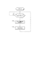
- FIG. 21 shows the relationship between the motion region detection process in the above embodiment and the complement determination process in this embodiment.
- the complement determination process (step S155) is a process for complementing the case where the motion region cannot be detected or the detected one is not appropriate in the result of the motion region detection process (step S153).
- the CPU 23 When the CPU 23 receives the data for the next frame, the CPU 23 performs a motion region detection process in step S153 in FIG.
- the motion region detection process motion detection is performed between frames at time t-1 and time t. In this case, since playback is paused at time t, there is a difference between both frames, so a motion region is detected.
- step S155 Details of step S155 are shown in FIG.
- the CPU 23 determines whether or not there is a motion area that has been detected immediately before at the current time, that is, at time t (step S201 in FIG. 22). In this case, since the motion region already exists at the time t-1 immediately before, the CPU 23 determines whether or not the motion region is detected at the time t (step S203).
- step S231 the CPU 23 determines whether or not the detected motion area is inside the motion area detected immediately before (step S221). ). In this case, since the detected motion area is the same as the motion area detected until immediately before, it is not the inner area, so the complement determination process is terminated.
- the CPU 23 determines whether data for the next frame has been received (step S151 in FIG. 21).
- the CPU 23 When the CPU 23 receives the data for the next frame, the CPU 23 performs a motion region detection process in step S153 in FIG. In the motion region detection process, it is determined whether or not a motion region is detected at time t + 1. Specifically, motion detection is performed between frames at time t and time t + 1. In this case, since playback is paused at time t, there is no difference between both frames at time t and time t + 1, and no motion is detected.
- the CPU 23 performs a complement determination process (step S155 in FIG. 21). That is, at time t + 1, it is determined whether or not there is a motion area that has been detected immediately before (step S201 in FIG. 22). In this case, since there is a motion region at the immediately preceding time t, the CPU 23 determines whether or not a motion region has been detected at time t + 1 (step S203).
- the CPU 23 determines whether or not a frame exists in the motion region detected until immediately before in the frame at time t + 1 ( FIG. 22 step S205).
- the frame detection for example, when there is a difference greater than or equal to a predetermined value by comparing pixel values inside and outside the frame, it is determined that there is an edge, and if the total number of edges exceeds a threshold, it is determined that a frame exists What should I do? Note that other well-known methods may be adopted as a method for detecting the presence of a frame.
- the CPU 23 determines whether or not to receive an image of the next frame (step S151 in FIG. 21), and when this is received, repeats the processing of steps S153 and S155.
- step S153 in FIG. 21 the motion region cannot be detected in step S153 in FIG. 21, and from time t + 2 to time t + 4, the CPU 23 proceeds to step S201-step S203-step S205-step S211 in FIG.
- the detected motion area is held.
- step S155 the CPU 23 proceeds from step S201 to step S203 to step S205.
- step S205 the CPU 23 determines that there is no frame in the coordinates of the motion area detected immediately before, and proceeds to step S207.
- the CPU 23 determines whether or not the case where there is no frame continues a plurality of times (step S207). In the present embodiment, the number of times in step S207 is “5”. In this case, since the case where there is no frame does not continue a plurality of times in succession, the CPU 23 keeps the motion area detected until immediately before (step S211).
- the CPU 23 determines whether or not to receive an image of the next frame (step S151 in FIG. 21), and when this is received, repeats the processing of steps S153 and S155.
- step S153 the motion region cannot be detected in step S153 in FIG. 21, and in step S155, from time t + 6 to time t + 8, the CPU 23 performs step S201-step S203-step S205-step S207 in FIG. Proceed to step S211, hold the motion area detected until immediately before.
- step S153 in FIG. 21 a motion region cannot be detected.
- step S155 at time t + 9, the CPU 23 proceeds to step S201-step S203-step S205-step S207 in FIG. Thus, it is determined that the case where there is no frame continues five times in succession, and the motion region detected until immediately before is discarded (step S213).
- step S205 when a motion region is not detected in step S203 of FIG. 22, the process of step S205 is performed. This is for conditional branching whether to perform the processing in step S221 and subsequent steps. Therefore, if it is determined only whether or not it is a temporary stop, if “YES” in the step S201, the process may be skipped to a step S205.
- the CPU 23 performs the motion region detection process of step S153 in FIG. 21 at time t. In this case, since only a part of the face is moving at time t, a small motion region 411 is detected as compared with the motion region 410 of the previous frame as shown in FIG.
- the CPU 23 proceeds to step S153 in FIG. Specifically, the CPU 23 determines whether or not there is a motion area that has been detected immediately before at time t (step S201 in FIG. 22).
- step S203 the CPU 23 determines whether or not a motion region has been detected at time t.
- the CPU 23 determines whether or not the detected motion region is inside the motion region that has been detected just before (step S221).
- the CPU 23 determines whether or not the number of times the inside is continuously detected is greater than or equal to the threshold (step S223). In the present embodiment, the number of times in step S223 is “5”.
- the CPU 23 determines that it is less than the threshold value, and determines whether or not the retention time of the motion area detected until immediately before is equal to or greater than the threshold value (step S225).
- the holding time threshold value in step S225 is set to 3 seconds.
- the CPU 23 determines that the retention time of the motion region detected until immediately before exceeds the threshold value, and is detected until just before.
- the moving area that has been kept is held as it is (step S211).
- step S225 when the holding time is equal to or greater than the threshold value in step S225, the motion area 410 detected until immediately before is held. As a result, it is possible to eliminate the case of erroneous detection. That is, if the motion region is held at the same position and the same size for a predetermined time and happens to be detected inside, it is recognized as a false detection and the process of step S211 is executed.
- the CPU 23 executes the same processing for the following frames. In this way, even when the detected motion region is inside the motion region that has been detected until just before, the original motion region can be retained.
- step S225 If the retention time of the motion area detected until immediately before in step S225 does not exceed the threshold value, it is determined whether there is a luminance change near the four corners of the motion area detected immediately before (step S227). ).
- step S229 to perform frame detection determination.
- the process of step S229 is the same as that of step S205. In this case, since there is a frame in the motion area, the process proceeds to step S211.
- the CPU 23 can keep the motion area detected until just before (step S211).
- step S225 the holding time becomes equal to or greater than the threshold value in step S225, and the process directly proceeds to step S211.
- step S227 will be described. As shown in FIG. 23, when the detected motion area is inside the motion area that has been detected until immediately before, only a part of the motion area in the motion area is the motion area, and the others are hardly moving. In addition to such a case, there is a case where another window overlaps a part of the moving area and the moving area is hidden. In such a case, at least one of the hidden areas includes any of the four corners of the detected area, and the luminance changes. Therefore, if there is a luminance change in at least one of the four corners of the motion area detected until immediately before, the process proceeds to step S211. If not, the process of step S229 is performed.
- step S229 if another window is overlapped with a part of the motion area and the motion area is hidden, it is determined in step S229 that there is no frame in the motion area that has been detected immediately before.
- the motion area is set as a new motion area (step S231). Note that it is possible to adjust how much overlap is required by adjusting the threshold value for detecting the frame.
- step S227 If there is no change in luminance at one or more places in step S227, the process may proceed to step S231 without proceeding to step S229.
- step S151 the CPU 23 determines whether or not data for the next frame has been received in step S151 (step S151 in FIG. 21). When it is received, the processing of step S153 and step S155 is repeated.
- step S223 when the number of times the inside is continuously detected is equal to or greater than the threshold value, the determination in step S229 is performed without performing the determination in steps S225 and S227. Thereby, in the case of repeatedly detecting the inside, the frame determination in step S229 can be performed.
- step S227, step S229, and step S231 have the following effects.
- the reliability of the result is relatively low. This is because a large amount is often erroneously detected by movement of a mouse pointer or a progress bar. Therefore, if it is not long after the motion region is detected, it is detected when there is no change in luminance in one of the four corners of the current detection region and the frame does not exist.
- the set inner area is reset as the movement area.
- the determination is made at at least one of the four corners as the determination criterion in step S227.
- determination may be made at a total of five in one center. Good.
- it may be determined whether there is a luminance change at the center.
- step S221 if the detected motion area is not inside the motion area that has been detected immediately before, the motion area has been moved or enlarged, so that it is detected until just before the present case.
- the process of retaining the motion area that has been performed is not performed. That is, the area detected by the normal motion detection process in step S153 in FIG. 21 is detected as a motion area.
- FIG. 24 shows a block diagram when the processing of FIGS. 21 and 22 is realized by hardware.
- the motion region coordinate detector 601 outputs a motion region candidate (1) candidate at time t using the images at time t-1 and time t.
- the determiner 603 selects either the motion region candidate (1) at time t or a motion coordinate candidate (2) at time t, which will be described later, and outputs the motion region at time t at time t.
- the holder 604 holds the motion region (coordinates) at the time t, and gives it to the designated region feature detector 605 as the motion coordinate at the time t + 1 at the time t + 1. Give it as a motion coordinate candidate (2).
- the designated region feature detector 605 applies the motion coordinates at the time t given from the determiner 603 to the images at the time t and the time t + 1 at the time t + 1, and features around the motion coordinates at the time t.
- Data d (t) and feature data d (t + 1) around the motion coordinate at time t + 1 are calculated and given to the determiner 603.
- the determiner 603 determines whether or not a frame exists from the feature data d (t + 1). Further, it is determined from the feature data d (t) and the feature data d (t + 1) whether there are luminance changes at the four corners (step S227 in FIG. 22).
- the boundary of the rectangular motion image region whose outline is rectangular is determined based on the difference between the image of the frame at time t and the frame at time t + 1.
- the rectangular motion image region determination method can be executed by the following steps.
- a motion unit block determination step for dividing the display area into unit blocks each including a predetermined number of pixels, and determining whether each unit block is a motion unit block in which motion exists, for each unit block In the column direction which is the direction in which each row is arranged, when including at least one motion unit block, the motion row block determining step for determining that the row is a motion row block, for each unit block, When at least one motion unit block is included in the row direction in which a column is arranged, a motion column block determining step for determining that the column is a motion column block, of the motion row blocks, adjacent If there are more than a threshold value of moving row blocks, the outline row block straight line of the set row block of these row blocks And when there is an adjacent motion sequence block that is equal to or greater than a threshold value among the motion sequence blocks, an outline row block straight line of a set row block of these column blocks is defined, and the external row block straight line and the external row block straight line
- a first rectangular motion image region determination step for determining a rectangular region surrounded
- the motion region coordinate detector 601 uses an image of a different frame from the designated region feature detector 605. You may make it give to. Specifically, the inclusion relationship is determined between the motion region obtained from the frames at time t-1 and time t and the motion region obtained from the frames at time t and time t + 1.
- the frame may be determined from the motion region obtained from the frame at time t and time t + n and the motion region obtained from the frame at time t + m and time t + p.
- n, m, and p are integers that satisfy n ⁇ m and p ⁇ m.
- the designated region feature detector 605 may be provided with frames at time t + a and time t + b.
- a and b are integers satisfying m ⁇ b, m ⁇ a, and a ⁇ b.
- scroll determination is performed for a specific moving image area, and boundary determination is not performed when the character area is scrolled. Such scroll determination can be used to determine whether or not the specific area is a text area.
- the line when the difference in the number of edges from the previous line for each line exceeds a threshold, the line is detected as a feature line, and the total number of detected feature lines exceeds the threshold.
- the specific rectangular area is determined to be a character area.
- the character mixed region is based on whether or not the maximum number of consecutive non-edges in each line is equal to or greater than a threshold, instead of the edge difference between the two lines.
- a threshold instead of the edge difference between the two lines.
- the CPU 23 initializes the feature line total number k (step S221 in FIG. 26), and initializes the continuous edgeless number r (step S223).
- Step S224 judges whether it is the start of continuous no edge. Whether or not it is the start of continuous no-edge can be determined by determining whether the pixel is a pixel that is not an edge for the first time in the row, or whether an edge pixel is changed to a non-edge pixel. Note that whether or not each pixel is an edge may be determined based on a luminance difference from surrounding pixels as described above.
- step S224 When the determination in step S224 is “yes”, the CPU 23 increments the continuous no-edge number r (step S225) and determines whether or not the continuous no-edge has ended (step S226). Whether or not it is the end of continuous no-edge can be determined by determining whether a non-edge pixel has changed to an edge pixel or whether the last pixel in the line is a non-edge pixel.
- the CPU 23 stores the current r number as a candidate (step S227).
- CPU 23 determines whether all the pixels in the line have been determined (step S231). If all the determinations have not been made, the CPU 23 repeats steps S223 to S227.
- step S224 If the determination in step S224 is “no”, the process in step S224 is repeated.
- step S231 If the CPU 23 determines that all the pixels in the row have been determined in step S231, the CPU 23 extracts the maximum value from the candidates (step S233), and further deletes all the candidates. CPU23 judges whether the extracted maximum value is larger than a threshold value (step S234).
- row L1 in FIG. 25 is determined as a feature line.
- the row L2 is not determined as a feature line.
- CPU23 increments the characteristic line total number k, when the said maximum value is larger than a threshold value (step S235).
- the CPU 23 determines whether all rows have been determined (step S241). If all the rows have not been determined, the CPU 23 repeats step S223 and subsequent steps.
- step S243 determines whether or not it is a character area.
- the area is determined to be a character area.
- the threshold thk may be determined as appropriate, but in the present embodiment, it is set to 30% of the total number of rows in the area.
- the line is determined as a feature line.
- the maximum value of the continuous edgeless number is equal to or greater than the threshold value.
- Such character region determination can also prevent the region from being determined to be a moving image when scrolling and moving characters in the browser, as in the fourth embodiment.
- the scroll determination may be performed on a part of lines instead of all lines in the area.
- scroll determination is not limited to this method, and may be a well-known scroll determination.
- the scroll region determination apparatus is a scroll region determination device that determines whether or not a determination target region in a screen is a scroll region, and for each pixel of the determination target region, Edge pixel determination means for determining whether or not an edge is based on the difference, and determines a row or column in which a predetermined number of pixels that are not the edge exist continuously in the same row or column as the character gap existence region Character gap existence area determination means, and scroll area determination means for determining whether or not the character gap existence area is a scroll area based on a ratio of the character gap existence area to the determination target area.
- Such a scroll determination method can be arbitrarily combined with the invention disclosed in the present embodiment.
- the character mixed region determination device is a character mixed region determination device that determines whether or not a determination target region in a screen is a character mixed region, and for each pixel of the determination target region, Edge pixel determination means for determining whether or not an edge is based on a difference in pixel values, a line or column in which a predetermined number of pixels that are not the edge exist continuously in the same row or column, Character gap area determining means for determining as a character gap row, and character mixture area determining means for determining whether the character gap area is based on the ratio of the character gap area to the determination target area.
- Such a character mixed area determination device can be arbitrarily combined with the rectangle detection method disclosed in the present embodiment.
- the scroll region determination apparatus determines that the determination target region is not a moving image region if the determination target region is a scroll region after being determined as a moving image region. As can be grasped.
- the luminance value is adopted as the pixel value, but it may be an RGB value or the like.
- step S15 in FIG. 5 it is determined whether or not the t-th frame and the t + 1-th frame are blocks constituting a moving image area. For example, it may be determined whether there is movement between the t-th frame and the t + 2 frame. Further, instead of comparing the two frames, the determination may be made by adding the front and rear frames.
- the same frame image is adopted as the frame image input to the motion region coordinate detector 601 and the image input to the designated region feature detector 605, but the present invention is not limited to this.
- the motion region coordinate detector 601 is provided with images of the t-th frame and the t + 3th frame
- the designated region feature detector 605 is provided with images of the (t + 1) th frame and the t + 2th frame. May be.
- the motion region coordinate detector 601 is provided with images of the t-th frame and the t + n frame
- the designated region feature detector 605 is provided with images of the t + a frame and the t + b frame. do it.
- a, b, and n are integers that satisfy n ⁇ b> a ⁇ 0.
- the designated region feature detector 605 applies the motion coordinates at time t given from the determiner 603 to the images at time t + a and time t + b at time t + 1, and
- the feature data d (t + a) around the motion coordinate and the feature data d (t + b) around the motion coordinate at time t + b are calculated and given to the determiner 603.
- the determiner 603 determines whether or not a frame exists from the feature data d (t + b). Further, it may be determined from the feature data d (t + a) and the feature data d (t + b) whether there is a luminance change at the four corners.
- the boundary line determination process in step S9 in FIG. 3 is arbitrary, and may not be performed when the boundary line in pixel units is not necessary.
- all the pixel values in one row or all the columns are used for all the blocks located on the outer periphery, but a partial thinning process or a representative value may be employed. Moreover, you may make it judge with some blocks instead of all the blocks.
- step S15 of FIG. 5 the past representative values at the same position may be held and compared.
- one block is composed of 32 * 32 pixels, but the present invention is not limited to this.
- step S9 When the value of any pixel itself (for example, the pixel value at the upper left corner of the block) is used instead of the average value or hash value of the pixels, the processing of step S9 in FIG. Then, the boundary may be obtained. For example, when 7 * 5 blocks are detected as a motion image area in the process of step S7, the process of step S9 is performed with 9 * 7 blocks added by one block around the block.
- the set top box may be configured as a switching hub for switching the output destination monitor of input data.
- a rectangular motion image area can be detected with one pixel accuracy. Furthermore, a plurality of rectangular motion image areas can be determined. In addition, it is possible to remove a small area movement with a small width. For example, it is possible to take measures against pseudo movements such as a mouse pointer. Moreover, since these can be distinguished with respect to the movement area
- the display area is divided into unit blocks each including a predetermined number of pixels, and the pixel values of the predetermined number of pixels belonging to each unit block are set. Based on this, the representative pixel value of each unit block is calculated and compared with the representative value of the unit block at the same position in the comparison target frame for each unit block.
- Judged as a motion unit block that exists the present invention is not limited to this, and a method that can determine whether each unit block is a motion unit block in which motion exists may be employed. For example, as already described, it is possible to employ a well-known motion unit block determination step, such as comparing the sum of representative values of the same blocks of a predetermined number of frames.
Landscapes
- Engineering & Computer Science (AREA)
- Multimedia (AREA)
- Signal Processing (AREA)
- Theoretical Computer Science (AREA)
- Physics & Mathematics (AREA)
- General Physics & Mathematics (AREA)
- Computer Vision & Pattern Recognition (AREA)
- Image Analysis (AREA)
- Transforming Electric Information Into Light Information (AREA)
- Television Systems (AREA)
- Picture Signal Circuits (AREA)
- Compression Or Coding Systems Of Tv Signals (AREA)
- Closed-Circuit Television Systems (AREA)
Priority Applications (7)
| Application Number | Priority Date | Filing Date | Title |
|---|---|---|---|
| CN201280073148.7A CN104285241B (zh) | 2012-04-03 | 2012-12-20 | 运动图像区域判定装置或其方法 |
| IN8790DEN2014 IN2014DN08790A (enExample) | 2012-04-03 | 2012-12-20 | |
| RU2014137566A RU2623890C2 (ru) | 2012-04-03 | 2012-12-20 | Устройство для определения области движущегося изображения и способ |
| EP20175530.3A EP3716208B1 (en) | 2012-04-03 | 2012-12-20 | Moving image area assessment device or method thereof |
| US14/390,225 US9332161B2 (en) | 2012-04-03 | 2012-12-20 | Moving image region determination device and method thereof |
| EP12873525.5A EP2835785B1 (en) | 2012-04-03 | 2012-12-20 | Moving image area assessment device or method thereof |
| AU2012376388A AU2012376388B2 (en) | 2012-04-03 | 2012-12-20 | Moving image region determination device and method thereof |
Applications Claiming Priority (4)
| Application Number | Priority Date | Filing Date | Title |
|---|---|---|---|
| JP2012-084660 | 2012-04-03 | ||
| JP2012084660 | 2012-04-03 | ||
| JP2012-146851 | 2012-06-29 | ||
| JP2012146851A JP5192597B1 (ja) | 2012-04-03 | 2012-06-29 | 動き画像領域判定装置またはその方法 |
Publications (1)
| Publication Number | Publication Date |
|---|---|
| WO2013150689A1 true WO2013150689A1 (ja) | 2013-10-10 |
Family
ID=48533972
Family Applications (1)
| Application Number | Title | Priority Date | Filing Date |
|---|---|---|---|
| PCT/JP2012/082992 Ceased WO2013150689A1 (ja) | 2012-04-03 | 2012-12-20 | 動き画像領域判定装置またはその方法 |
Country Status (8)
| Country | Link |
|---|---|
| US (1) | US9332161B2 (enExample) |
| EP (2) | EP3716208B1 (enExample) |
| JP (2) | JP5192597B1 (enExample) |
| CN (1) | CN104285241B (enExample) |
| AU (1) | AU2012376388B2 (enExample) |
| IN (1) | IN2014DN08790A (enExample) |
| RU (1) | RU2623890C2 (enExample) |
| WO (1) | WO2013150689A1 (enExample) |
Families Citing this family (4)
| Publication number | Priority date | Publication date | Assignee | Title |
|---|---|---|---|---|
| JP5895242B2 (ja) * | 2011-10-19 | 2016-03-30 | パナソニックIpマネジメント株式会社 | 蝟集判定装置及び蝟集判定方法 |
| KR20160014915A (ko) * | 2014-07-30 | 2016-02-12 | 삼성전자주식회사 | 디스플레이장치 및 그 제어방법 |
| CN109729298B (zh) * | 2017-10-27 | 2020-11-06 | 联咏科技股份有限公司 | 图像处理方法与图像处理装置 |
| US10762866B2 (en) * | 2018-08-30 | 2020-09-01 | Synaptics Incorporated | Display rescan |
Citations (2)
| Publication number | Priority date | Publication date | Assignee | Title |
|---|---|---|---|---|
| JPH117266A (ja) | 1997-06-17 | 1999-01-12 | Matsushita Electric Ind Co Ltd | ディスプレイパネルの映像表示方式およびその装置 |
| JP2009064199A (ja) * | 2007-09-05 | 2009-03-26 | Casio Comput Co Ltd | ジェスチャー認識装置及びジェスチャー認識方法 |
Family Cites Families (19)
| Publication number | Priority date | Publication date | Assignee | Title |
|---|---|---|---|---|
| JPH03126181A (ja) * | 1989-10-11 | 1991-05-29 | Oki Electric Ind Co Ltd | 文書画像の領域分割方法 |
| US5588067A (en) * | 1993-02-19 | 1996-12-24 | Peterson; Fred M. | Motion detection and image acquisition apparatus and method of detecting the motion of and acquiring an image of an object |
| JP3230509B2 (ja) * | 1998-06-26 | 2001-11-19 | 日本電気株式会社 | 動画像処理装置 |
| RU2189628C2 (ru) * | 2000-04-04 | 2002-09-20 | Свириденко Андрей Владимирович | Способ дистанционного управления |
| RU2262661C2 (ru) * | 2000-06-26 | 2005-10-20 | Череповецкий научный координационный центр Российской Академии Наук (ЧНКЦ РАН) | Способ обнаружения движущихся транспортных средств |
| EP1403817A4 (en) * | 2000-09-06 | 2007-06-06 | Hitachi Ltd | DETECTOR FOR ABNORMES BEHAVIOR |
| US7266220B2 (en) * | 2002-05-09 | 2007-09-04 | Matsushita Electric Industrial Co., Ltd. | Monitoring device, monitoring method and program for monitoring |
| JP2006091980A (ja) * | 2004-09-21 | 2006-04-06 | Seiko Epson Corp | 画像処理装置、画像処理方法および画像処理プログラム |
| CN101288101A (zh) * | 2005-07-26 | 2008-10-15 | 皇家飞利浦电子股份有限公司 | 根据小规模重建的运动分析进行的心区检测 |
| KR101336475B1 (ko) * | 2005-09-26 | 2013-12-04 | 미쓰비시덴키 가부시키가이샤 | 동화상 부호화 장치 및 동화상 복호 장치 |
| US20070223818A1 (en) * | 2006-03-27 | 2007-09-27 | Honeywell International Inc. | Method and apparatus for predicting the accuracy of virtual Scene based on incomplete information in video |
| JP4659793B2 (ja) * | 2007-08-07 | 2011-03-30 | キヤノン株式会社 | 画像処理装置及び画像処理方法 |
| CN101320478B (zh) * | 2008-07-23 | 2010-06-02 | 北京蓝色星际软件技术发展有限公司 | 一种基于帧差的多重帧间形态学区域探测方法 |
| JP5116602B2 (ja) * | 2008-08-04 | 2013-01-09 | キヤノン株式会社 | 映像信号処理装置及び方法、プログラム |
| JP5421072B2 (ja) * | 2008-11-19 | 2014-02-19 | クラリオン株式会社 | 接近物体検知システム |
| CN101588445B (zh) * | 2009-06-09 | 2011-01-19 | 宁波大学 | 一种基于深度的视频感兴趣区域提取方法 |
| US9082278B2 (en) * | 2010-03-19 | 2015-07-14 | University-Industry Cooperation Group Of Kyung Hee University | Surveillance system |
| US20120300046A1 (en) * | 2011-05-24 | 2012-11-29 | Ilya Blayvas | Method and System for Directed Light Stereo Display |
| JP4980486B1 (ja) * | 2011-06-14 | 2012-07-18 | 株式会社ナナオ | 動き画像領域判定装置またはその方法 |
-
2012
- 2012-06-29 JP JP2012146851A patent/JP5192597B1/ja active Active
- 2012-11-16 JP JP2012252040A patent/JP5690800B2/ja active Active
- 2012-12-20 WO PCT/JP2012/082992 patent/WO2013150689A1/ja not_active Ceased
- 2012-12-20 EP EP20175530.3A patent/EP3716208B1/en active Active
- 2012-12-20 AU AU2012376388A patent/AU2012376388B2/en not_active Ceased
- 2012-12-20 US US14/390,225 patent/US9332161B2/en active Active
- 2012-12-20 RU RU2014137566A patent/RU2623890C2/ru not_active IP Right Cessation
- 2012-12-20 IN IN8790DEN2014 patent/IN2014DN08790A/en unknown
- 2012-12-20 CN CN201280073148.7A patent/CN104285241B/zh active Active
- 2012-12-20 EP EP12873525.5A patent/EP2835785B1/en active Active
Patent Citations (2)
| Publication number | Priority date | Publication date | Assignee | Title |
|---|---|---|---|---|
| JPH117266A (ja) | 1997-06-17 | 1999-01-12 | Matsushita Electric Ind Co Ltd | ディスプレイパネルの映像表示方式およびその装置 |
| JP2009064199A (ja) * | 2007-09-05 | 2009-03-26 | Casio Comput Co Ltd | ジェスチャー認識装置及びジェスチャー認識方法 |
Also Published As
| Publication number | Publication date |
|---|---|
| JP5192597B1 (ja) | 2013-05-08 |
| US20150077638A1 (en) | 2015-03-19 |
| IN2014DN08790A (enExample) | 2015-05-29 |
| JP2013232175A (ja) | 2013-11-14 |
| JP5690800B2 (ja) | 2015-03-25 |
| EP2835785A1 (en) | 2015-02-11 |
| EP2835785B1 (en) | 2020-07-08 |
| CN104285241A (zh) | 2015-01-14 |
| AU2012376388B2 (en) | 2015-06-25 |
| US9332161B2 (en) | 2016-05-03 |
| EP3716208B1 (en) | 2021-06-23 |
| EP3716208A1 (en) | 2020-09-30 |
| CN104285241B (zh) | 2017-08-01 |
| RU2623890C2 (ru) | 2017-06-29 |
| AU2012376388A1 (en) | 2014-10-16 |
| RU2014137566A (ru) | 2016-05-27 |
| EP2835785A4 (en) | 2016-01-27 |
| JP2013232173A (ja) | 2013-11-14 |
Similar Documents
| Publication | Publication Date | Title |
|---|---|---|
| EP2709039A1 (en) | Device and method for detecting the presence of a logo in a picture | |
| JP5006479B1 (ja) | 動き画像領域判定装置またはその方法 | |
| CN106575362A (zh) | 基于关注区融合的对象选择 | |
| EP3376470A1 (en) | Moving body tracking method, moving body tracking device, and program | |
| JP5690800B2 (ja) | 動き画像領域判定装置またはその方法 | |
| CN112752158A (zh) | 一种视频展示的方法、装置、电子设备及存储介质 | |
| US10482610B2 (en) | Detection of partially motion-blurred video frames | |
| US9613427B2 (en) | Information processing method and electronic device | |
| JP5542981B1 (ja) | 画像処理装置、フレームレートコントロール処理判定装置またはその方法 | |
| JP7700165B2 (ja) | 画像処理装置、画像処理方法及びプログラム | |
| JP2013186610A (ja) | 文字抽出装置および文字抽出プログラム | |
| CN119893318A (zh) | 图像处理方法、装置、设备及介质 | |
| JP2015142160A (ja) | 画像処理装置、画像処理方法、及び、プログラム |
Legal Events
| Date | Code | Title | Description |
|---|---|---|---|
| 121 | Ep: the epo has been informed by wipo that ep was designated in this application |
Ref document number: 12873525 Country of ref document: EP Kind code of ref document: A1 |
|
| WWE | Wipo information: entry into national phase |
Ref document number: 14390225 Country of ref document: US |
|
| NENP | Non-entry into the national phase |
Ref country code: DE |
|
| ENP | Entry into the national phase |
Ref document number: 2012376388 Country of ref document: AU Date of ref document: 20121220 Kind code of ref document: A |
|
| WWE | Wipo information: entry into national phase |
Ref document number: 2012873525 Country of ref document: EP |
|
| ENP | Entry into the national phase |
Ref document number: 2014137566 Country of ref document: RU Kind code of ref document: A |