WO2013146019A1 - 撮像装置 - Google Patents
撮像装置 Download PDFInfo
- Publication number
- WO2013146019A1 WO2013146019A1 PCT/JP2013/054980 JP2013054980W WO2013146019A1 WO 2013146019 A1 WO2013146019 A1 WO 2013146019A1 JP 2013054980 W JP2013054980 W JP 2013054980W WO 2013146019 A1 WO2013146019 A1 WO 2013146019A1
- Authority
- WO
- WIPO (PCT)
- Prior art keywords
- image
- finder
- subject
- live view
- exposure
- Prior art date
- Legal status (The legal status is an assumption and is not a legal conclusion. Google has not performed a legal analysis and makes no representation as to the accuracy of the status listed.)
- Ceased
Links
Images


Classifications
-
- G—PHYSICS
- G03—PHOTOGRAPHY; CINEMATOGRAPHY; ANALOGOUS TECHNIQUES USING WAVES OTHER THAN OPTICAL WAVES; ELECTROGRAPHY; HOLOGRAPHY
- G03B—APPARATUS OR ARRANGEMENTS FOR TAKING PHOTOGRAPHS OR FOR PROJECTING OR VIEWING THEM; APPARATUS OR ARRANGEMENTS EMPLOYING ANALOGOUS TECHNIQUES USING WAVES OTHER THAN OPTICAL WAVES; ACCESSORIES THEREFOR
- G03B17/00—Details of cameras or camera bodies; Accessories therefor
- G03B17/18—Signals indicating condition of a camera member or suitability of light
- G03B17/20—Signals indicating condition of a camera member or suitability of light visible in viewfinder
-
- G—PHYSICS
- G03—PHOTOGRAPHY; CINEMATOGRAPHY; ANALOGOUS TECHNIQUES USING WAVES OTHER THAN OPTICAL WAVES; ELECTROGRAPHY; HOLOGRAPHY
- G03B—APPARATUS OR ARRANGEMENTS FOR TAKING PHOTOGRAPHS OR FOR PROJECTING OR VIEWING THEM; APPARATUS OR ARRANGEMENTS EMPLOYING ANALOGOUS TECHNIQUES USING WAVES OTHER THAN OPTICAL WAVES; ACCESSORIES THEREFOR
- G03B13/00—Viewfinders; Focusing aids for cameras; Means for focusing for cameras; Autofocus systems for cameras
- G03B13/02—Viewfinders
-
- G—PHYSICS
- G03—PHOTOGRAPHY; CINEMATOGRAPHY; ANALOGOUS TECHNIQUES USING WAVES OTHER THAN OPTICAL WAVES; ELECTROGRAPHY; HOLOGRAPHY
- G03B—APPARATUS OR ARRANGEMENTS FOR TAKING PHOTOGRAPHS OR FOR PROJECTING OR VIEWING THEM; APPARATUS OR ARRANGEMENTS EMPLOYING ANALOGOUS TECHNIQUES USING WAVES OTHER THAN OPTICAL WAVES; ACCESSORIES THEREFOR
- G03B13/00—Viewfinders; Focusing aids for cameras; Means for focusing for cameras; Autofocus systems for cameras
- G03B13/02—Viewfinders
- G03B13/06—Viewfinders with lenses with or without reflectors
-
- G—PHYSICS
- G03—PHOTOGRAPHY; CINEMATOGRAPHY; ANALOGOUS TECHNIQUES USING WAVES OTHER THAN OPTICAL WAVES; ELECTROGRAPHY; HOLOGRAPHY
- G03B—APPARATUS OR ARRANGEMENTS FOR TAKING PHOTOGRAPHS OR FOR PROJECTING OR VIEWING THEM; APPARATUS OR ARRANGEMENTS EMPLOYING ANALOGOUS TECHNIQUES USING WAVES OTHER THAN OPTICAL WAVES; ACCESSORIES THEREFOR
- G03B15/00—Special procedures for taking photographs; Apparatus therefor
-
- G—PHYSICS
- G03—PHOTOGRAPHY; CINEMATOGRAPHY; ANALOGOUS TECHNIQUES USING WAVES OTHER THAN OPTICAL WAVES; ELECTROGRAPHY; HOLOGRAPHY
- G03B—APPARATUS OR ARRANGEMENTS FOR TAKING PHOTOGRAPHS OR FOR PROJECTING OR VIEWING THEM; APPARATUS OR ARRANGEMENTS EMPLOYING ANALOGOUS TECHNIQUES USING WAVES OTHER THAN OPTICAL WAVES; ACCESSORIES THEREFOR
- G03B19/00—Cameras
- G03B19/02—Still-picture cameras
- G03B19/12—Reflex cameras with single objective and a movable reflector or a partly-transmitting mirror
-
- H—ELECTRICITY
- H04—ELECTRIC COMMUNICATION TECHNIQUE
- H04N—PICTORIAL COMMUNICATION, e.g. TELEVISION
- H04N23/00—Cameras or camera modules comprising electronic image sensors; Control thereof
- H04N23/60—Control of cameras or camera modules
- H04N23/63—Control of cameras or camera modules by using electronic viewfinders
-
- H—ELECTRICITY
- H04—ELECTRIC COMMUNICATION TECHNIQUE
- H04N—PICTORIAL COMMUNICATION, e.g. TELEVISION
- H04N23/00—Cameras or camera modules comprising electronic image sensors; Control thereof
- H04N23/70—Circuitry for compensating brightness variation in the scene
- H04N23/73—Circuitry for compensating brightness variation in the scene by influencing the exposure time
-
- H—ELECTRICITY
- H04—ELECTRIC COMMUNICATION TECHNIQUE
- H04N—PICTORIAL COMMUNICATION, e.g. TELEVISION
- H04N23/00—Cameras or camera modules comprising electronic image sensors; Control thereof
- H04N23/60—Control of cameras or camera modules
- H04N23/67—Focus control based on electronic image sensor signals
- H04N23/672—Focus control based on electronic image sensor signals based on the phase difference signals
Definitions
- the present invention relates to an imaging apparatus, and more particularly, to an imaging apparatus that includes an optical viewfinder and an electronic viewfinder and is capable of switching between them.
- an electronic image of a subject acquired by a photographing optical system such as a photographing lens and an image sensor is displayed on a liquid crystal monitor provided on the back of the camera body, and the composition and focus state are displayed.
- a device that performs a confirmation is provided, but in recent years, a model provided with a finder for confirming the composition and in-focus state apart from the liquid crystal monitor on the back surface is becoming widespread.
- viewfinder methods include an optical viewfinder (OVF: Optical View Finder, hereinafter referred to as OVF) and an electronic viewfinder (EVF: Electronic View Finder, hereinafter referred to as EVF), each having advantages and disadvantages.
- OVF has certain advantages over EVF, such as “no delay in response to display”, “display image is clear”, “it is easy to determine the composition because it can be seen outside the shooting range (by method)” There is.
- EVF has advantages over OVF, such as “display of reproduced images and menus (including superimposed display)”. Therefore, in a digital camera (imaging device) provided with both OVF and EVF, it is preferable that OVF and EVF can be switched appropriately according to the situation.
- a technique described in Patent Document 1 is known as an imaging apparatus that can switch a finder system.
- OVF movable mirror is inserted in the optical path and the optical image of the subject is visually recognized by the viewfinder eyepiece
- live view mode real-time image generated by the image sensor is displayed on the display unit
- EVF a movable mirror is contrasted from an optical path and an electronic image of a subject acquired by an image sensor is viewed on a liquid crystal monitor
- a technique described in Patent Document 2 is known as an imaging apparatus that can automatically switch the finder method.
- a shooting condition determination unit that determines conditions such as a remaining battery level, a light / dark difference in a shooting scene, a subject distance, and the like is provided to automatically switch between OVF and EVF based on the determination result. I have to.
- the present invention has been made in view of such circumstances, and in an imaging apparatus capable of switching between an optical viewfinder and an electronic viewfinder, a finder eyepiece before long-exposure shooting is performed.
- An object of the present invention is to provide an image pickup apparatus that can confirm a subject image that has been exposed for a long time and can recognize subtle changes such as when the image pickup apparatus is gradually tilted over a long period of time. .
- an imaging apparatus acquires a live view image before actual shooting and acquires a recorded image to be recorded on a recording medium in the actual shooting state, and long exposure shooting.
- Exposure control means for controlling the exposure time of the live view image acquired by the image sensor before the actual shooting in the same state in the actual shooting state, and a photographing optical system for forming an optical image on the light receiving surface of the image sensor.
- the finder optical system that guides the subject image to the eyepiece of the finder, the display means for displaying the live view image obtained by the image sensor for the finder, and the finder optical system as a finder image that is visually recognized from the eyepiece
- a finder image switching means capable of switching between the guided optical image and the live view image displayed by the display means, and a finder image before the main shooting in the state of long exposure shooting.
- a finder display control means for alternately switching a finder image visually recognized from the finder by the replacement means, an optical image guided by the finder optical system, and a long-view exposure live view image obtained by the image sensor. .
- live view image means that the image output from the image sensor is recorded on a recording medium or the like so that the photographer can check the angle of view and subject before shooting and recording by pressing the shutter button.
- Temporal recording in the RAM means a live view image displayed on the image display unit.
- the exposure time of the live view image acquired by the image sensor is controlled to be the same as the actual shooting state so that the live view image can be confirmed from the eyepiece of the viewfinder.
- the exposure time of the live view image acquired by the image sensor is controlled to be the same as the actual shooting state so that the live view image can be confirmed from the eyepiece of the viewfinder.
- an optical image guided by the finder optical system and a long-exposure live view image obtained by the image sensor are alternately switched.
- the finder image switching means includes both the optical image guided by the finder optical system and the subject image of only one of the live view image displayed by the display means.
- the viewfinder display control means superimposes both the optical image guided by the viewfinder optical system and the long-view exposure live view image obtained by the image sensor. You may make it switch to a to-be-photographed image.
- the exposure time of the live view image acquired by the image sensor is controlled to be the same as the actual shooting state so that the live view image can be confirmed from the eyepiece of the viewfinder.
- the exposure time of the live view image acquired by the image sensor is controlled to be the same as the actual shooting state so that the live view image can be confirmed from the eyepiece of the viewfinder.
- the live view image can only be confirmed from the eyepiece of the viewfinder, it cannot be confirmed if there is a large movement in the subject image during that time.
- the optical image guided by the finder optical system and the live view image for the long exposure are switched to the subject image superimposed.
- the apparatus includes a subject change detection unit that detects a difference between the latest subject image obtained from the image sensor and the previous subject image, and the finder display control unit is a state in which the subject change is detected by the subject change detection unit Therefore, it is preferable to switch the subject image visually recognized from the finder by the finder image switching means to the subject image formed by the finder optical system.
- the subject image information can be directly confirmed by OVF.
- the subject change detection means preferably determines whether or not the difference value indicating the difference between the latest subject image obtained from the image sensor and the previous subject image exceeds a preset threshold value.
- the subject change detection means is preferably an acceleration sensor.
- the subject change detection means determines whether or not the difference value indicating the magnitude of the difference between the latest subject image obtained from the image sensor and the previous subject image exceeds a preset threshold value, whereby the imaging device This allows the photographer to notice that the subject is slightly tilted or the subject image has moved greatly.
- the subject change detection means is an acceleration sensor
- the subject information can be directly confirmed by OVF while notifying the photographer that the imaging device is slightly tilted.
- the long exposure photography is 1 second or longer.
- a long-exposure subject image can be confirmed on the viewfinder eyepiece before the long exposure shooting, and the image pickup apparatus is gradually tilted for a long time. The subtle changes can be recognized.
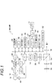
- FIG. 1 is a block diagram showing an embodiment of an imaging apparatus according to the present invention.
- the imaging device 1 is a digital camera that records captured still images and moving images on a memory card 10, and the operation of the entire camera is centrally controlled by a central processing unit (CPU) 12.
- CPU central processing unit
- the operation unit 14 of the imaging apparatus 1 includes a power switch, a shutter button, an optical viewfinder mode, an electronic viewfinder mode, an optical-electronic superposition viewfinder mode, a macro mode, a still image shooting mode, a moving image shooting mode, a playback mode, and an automatic focus adjustment (AF mode), a mode selector switch for switching manual focus adjustment (MF mode), and the like, and a multifunction cross key for outputting various command signals such as zoom and frame advance.
- Various operation signals from the operation unit 14 are applied to the CPU 12.
- the image light indicating the subject is imaged on the light receiving surface of the image pickup device (CCD) 20 through the focus lens that can be moved manually, the image pickup optical system 16 including the image pickup lens, and the diaphragm 18. Is done.
- the signal charge accumulated in the CCD 20 is sequentially read out as a voltage signal corresponding to the signal charge by a transfer pulse applied from the CCD driver 22.
- the CCD 20 has a so-called electronic shutter function that controls the charge accumulation time (shutter speed) of each photosensor according to the timing of the shutter gate pulse.
- the voltage signal sequentially read from the CCD 20 is applied to the analog processing unit 24.
- the analog processing unit 24 includes signal processing circuits such as a sampling hold circuit, a color separation circuit, and a gain adjustment circuit.
- the analog processing unit 24 performs correlated double sampling (CDS) processing and color separation processing on each of the R, G, and B color signals.
- CDS correlated double sampling
- the signal level is adjusted (pre-white balance processing).
- the signal output from the analog processing unit 24 is converted into a digital signal (hereinafter referred to as “CCDRAW data”) by the A / D converter 26 and then stored in a temporary storage device 28 such as an SDRAM.
- the temporary storage device 28 has a storage capacity capable of temporarily storing a plurality of CCDRAW data.
- the storage capacity of the temporary storage device 28 is not limited to this.
- the timing generator (TG) 30 provides timing signals to the CCD driver 22, the analog processing unit 24 and the A / D converter 26 in accordance with instructions from the CPU 12, and the circuits are synchronized by this timing signal. ing.
- the ROM 32 stores programs and adjustment values in advance, and these programs and adjustment values are read as appropriate.
- the signal processing unit 34 adjusts the gains of the R, G, and B signals to perform white balance (WB) correction, and has a predetermined gamma characteristic for each of the WB corrected R, G, and B signals.
- a gamma correction unit that performs gamma correction according to the stored ROM table, a color interpolation processing unit that performs color interpolation processing corresponding to the color filter array of the CCD 20, and generation processing (YC conversion) of luminance data Y and color difference data Cr and Cb.
- a YC processing unit that performs an edge enhancement by adding an aperture signal to the luminance data Y, a noise reduction processing unit that performs a noise reduction process such as a smoothing process and a median filter process, and color difference data Cr and Cb
- a saturation emphasizing unit that increases or decreases the gain of the signal, and sequentially performs signal processing on the CCDRAW data stored in the temporary storage device 28 by each processing unit.
- the image data processed by the signal processing unit 34 is encoded by the video encoder 38 and is output to a small liquid crystal display unit (LCD) 40 which is a display device which is one mode of the display unit. Displayed on the display screen.
- LCD liquid crystal display unit
- images continuously shot at a predetermined interval by the CCD 20 are processed for image display and then output to the LCD 40 and displayed as a live view image.
- the CCDRAW data photographed through the photographing optical system 16 and the CCD 20 and stored in the temporary storage device 28 is subjected to various signal processing by the signal processing unit 34 and converted into YC data. Thereafter, the YC data is output to the compression / decompression processing unit 36, and a predetermined compression process such as JPEG (Joint Photographic Experts Group) is executed.
- JPEG Joint Photographic Experts Group
- the automatic exposure (AE) detection unit 37 for example, integrates the G signals of the entire image, or integrates the G signals that are weighted differently in the central part and the peripheral part of the screen, and outputs the integrated value to the CPU 12.
- the CPU 12 calculates the brightness of the subject (shooting Ev value) from the integrated value input from the AE detection unit 37, and sets the F value of the diaphragm 18 and the electronic shutter (shutter speed) of the CCD 20 based on the shooting Ev value.
- the diaphragm 18 is controlled based on the determined F value
- the charge accumulation time in the CCD 20 is controlled via the CCD driver 22 based on the determined shutter speed.
- the focus shift amount calculation unit 46 detects the phase difference of the parallax image in the predetermined focus area among the parallax images obtained from the phase difference pixels of the CCD 20 including the phase difference pixel, and uses this as the information indicating the phase difference. Based on this, the amount of defocus (defocus amount) is obtained.
- the amount of focus deviation is based on an output signal of a known phase difference sensor or the like including a separator lens and a sensor for detecting the imaging position of two images separated by the separator lens. May be detected.
- the focus shift amount calculated by the focus shift amount calculation unit 46 can be used to control the focus lens of the photographing optical system 16 so that the focus shift amount becomes 0 in the AF mode, and will be described later. In addition, it is used for display control of the live view image on the LCD 40 in the MF mode.
- the focus lens position of the photographing optical system 16 is detected by the position sensor 48 and sent to the CPU 12. Based on the detection output of the position sensor 48, the CPU 12 determines the distance of the subject that is in focus according to the current position of the focus lens. Note that the position of the focus lens and the subject distance corresponding to the position are stored in advance in the ROM 32 or the like, and the CPU 12 reads the subject distance corresponding to the position of the focus lens from the ROM 32. Further, the subject distance may be measured by a baseline long triangular distance measuring sensor or the like. The subject distance thus measured can be used to control the focus lens of the photographing optical system 16 in the AF mode, and the live view image display control on the LCD 40 in the MF mode as described later. Used for. The position sensor 48 also detects the position (zoom position) of the zoom lens of the photographing optical system 16 and outputs information on the zoom position to the CPU 12.
- the imaging apparatus 1 includes an optical viewfinder (OVF) having an objective lens 50, an eyepiece lens 52, and a liquid crystal shutter 64.
- OVF optical viewfinder
- the liquid crystal shutter 64 is controlled by the CPU 12 and is in a transmissive state when the optical viewfinder is used. As a result, the optical image of the subject passes through the liquid crystal shutter 64 and can be observed by the eyepiece lens 52 through the objective lens 50.
- a beam splitter 54 is provided between the objective lens 50 and the eyepiece lens 52, and the beam splitter 54 generates an optical image of a subject incident on the objective lens 50 and a live view image displayed on the LCD 40. Used as a means of synthesis. That is, the optical image incident on the objective lens 50 can be observed by the eyepiece 52 through the beam splitter 54, and the live view image displayed on the LCD 40 is reflected by the beam splitter 54 at a right angle and is in the eyepiece. Observation is possible with the lens 52.
- the LCD 40, the beam splitter 54, and the eyepiece lens 52 constitute an electronic viewfinder (EVF) that can observe a live view image.
- EMF electronic viewfinder
- the liquid crystal shutter 64 in a light-shielded state, only the image from the LCD 40 can be observed from the eyepiece lens 52.
- the liquid crystal shutter 64 in a transmissive state, it is possible to superimpose a live view image on the LCD 40 and an optical image transmitted through the objective lens 50.
- the imaging apparatus 1 includes a hybrid finder that enables switching between OVF optical image display, EVF image display, and superimposed display of OVF and EVF images. That is, a finder image switching means is provided.
- the parallax occurs between the optical image in the predetermined focus area and the live view image according to the distance of the subject in the focus area.
- the CPU 12 moves the display position of the live view image displayed on the LCD 40 so as to correct the parallax generated according to the determined subject distance. Thereby, it is possible to display the optical image in the focus area so that the live view image matches.
- the imaging apparatus 1 includes an exposure control means 60 and a finder display control means 62.
- the exposure control means 60 controls the exposure time of the live view image acquired by the CCD (imaging device) 20 to be the same as the state of the main shooting. That is, by controlling the exposure time of the live view image acquired by the CCD 20 to be the same as the actual photographing state, the live view image can be confirmed from the eyepiece (eyepiece portion) 52 of the finder. As a result, it is possible to confirm from the eyepiece 52 of the finder before the main shooting of the long exposure shooting how the recorded image in the main shooting looks.
- the exposure time of the live view image is controlled to be the same as the actual shooting state, it is difficult to notice a subtle change (a subtle field angle deviation) such as a case where the imaging apparatus 1 is gradually tilted for a long time. .
- an optical image (OVF optical image display) guided by the finder optical system by the finder display control means 62 and a long-exposure live view image (EVF image display) obtained by the CCD 20 are further provided. , And so on.
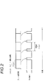
- FIG. 2 is an explanatory diagram for explaining switching control between OVF and EVF.
- the charge is accumulated in the CCD 20 via the CCD driver 22 by the exposure control means 60 for the shutter speed time S during the actual photographing. Then, a long-view live view image is displayed on the LCD 40 via the analog processing unit 24 and the A / D converter 26. While the live view image is displayed on the LED 40, the liquid crystal shutter 64 is put in a light shielding state by the finder display control means 62. Thereby, the live view image displayed on the LCD 40 can be recognized from the LCD 40 from the eyepiece lens 52.
- the finder display control means 62 alternately switches between OVF optical image display and EVF image display at a period S of the exposure time of the live view image. For example, in the case of 10-second exposure, as shown in FIG. 2, the display is switched to an alternate image of the EVF long exposure live view image and the OVF optical image display every 10 seconds from the OVF display. For example, the EVF long exposure live view image is displayed for 1 second and the OVF optical image is displayed for 9 seconds, and this switching is repeated.
- long exposure photography means that the shutter speed is 1 second or more.
- the imaging apparatus 1 includes an exposure control means 60 and a finder display control means 62.
- the exposure time of the live view image acquired by the CCD (imaging device) 20 by the exposure control means 60 is the state of the main shooting before the main shooting of the long exposure shooting, as in the first embodiment. Control the same. That is, by controlling the exposure time of the live view image acquired by the CCD 20 to be the same as the actual photographing state, the live view image can be confirmed from the eyepiece (eyepiece portion) 52 of the finder. As a result, it is possible to confirm from the eyepiece lens 52 of the finder before the main shooting for the long exposure shooting how the recorded image looks in the state of the main shooting.
- the exposure time of the live view image is controlled to be the same as the actual shooting state, it cannot be confirmed if there is a large movement in the subject image during that time.
- the finder display control means 62 further superimposes both the optical image guided by the finder optical system and the long-view live view image before the main shooting at the time of long exposure shooting. Changed to the subject image.
- the charge is accumulated in the CCD 20 via the CCD driver 22 by the exposure control means 60 for the shutter speed time S during the actual photographing. Then, a long-view live view image is displayed on the LCD 40 via the analog processing unit 24 and the A / D converter 26. While the live view image is displayed on the LED 40, the liquid crystal shutter 64 is set to the transmissive state by the finder display control means 62. As a result, a subject image obtained by superimposing both the live view image displayed on the LCD 40 and the OVF optical image can be recognized from the eyepiece lens 52.
- a subject change detection unit 66 is provided. 3 is an excerpt of the EVF optical system 90 and the OVF optical system 92 shown in FIG. 1, and further includes a subject change detection means 66 in FIG.
- the exposure time of the live view image acquired by the CCD (imaging device) 20 is controlled by the exposure control means 60 to be the same as the state of the main shooting before the main shooting of the long exposure shooting.
- the subject image obtained from the CCD 20 is updated every exposure time.
- subject change detection means 66 by detecting the difference between the latest subject image and the previous subject image, it is detected that the imaging device 1 is slightly tilted or the subject image has moved greatly. be able to.
- the subject change detection means 66 When the subject change is detected by the subject change detection means 66, the subject image viewed from the viewfinder is switched to only the subject image of the OVF optical system 92.
- the object image information can be directly confirmed by the OVF optical system 92.
- the subject change detection means 66 determines whether or not the difference value indicating the magnitude of the difference between the latest subject image obtained from the image sensor and the previous subject image exceeds a preset threshold value. Is preferred.
- the subject change detection means determines whether or not the difference value indicating the magnitude of the difference between the latest subject image obtained from the image sensor and the previous subject image exceeds a preset threshold value. Can be noticed to the photographer that the camera is slightly tilted or the subject image has moved greatly.
- the subject change detection means is an acceleration sensor
- the subject information can be directly confirmed by OVF while notifying the photographer that the imaging device is slightly tilted.
- the subject change detection means 66 may be an acceleration sensor (not shown).
- the acceleration sensor is provided in an imaging apparatus having a shift correction function in the photographing optical system 16.
- An acceleration sensor provided in the imaging device is used to detect that the imaging device is tilted slightly. When tilting is detected, only the subject image of the OVF optical system 92 is recognized as a subject image visually recognized from the viewfinder. By switching to, information on the subject can be directly confirmed by the OVF while notifying the photographer that the imaging device is slightly tilted.
- the image pickup apparatus 1 shown in FIG. 1 is applied with an OVF optical axis different from the optical axis of the photographing optical system 16, but the OVF optical axis is the same as that of the photographing optical system 80 as shown in FIG.
- the present invention can also be applied to a single-lens reflex finder having the following optical axes.
- subject light incident on the photographing optical system 80 is incident on the CCD 82 via the translucent quick return mirror 82, and part of the light is reflected on the quick return mirror 82 and incident on the focus plate 86. To do.
- the optical image guided on the focus plate 86 can be confirmed through the eyepiece 88 and the pentaprism 70.
- a transmissive LCD 72 is disposed on the focus plate 86, and a live view image taken by the CCD 84 is displayed.
- the live view image can be confirmed through the eyepiece 88 and the pentaprism 70 in the same manner as the optical image, thereby forming a hybrid viewfinder.
- SYMBOLS 1 ... Imaging device, 10 ... Memory card, 12 ... Central processing unit (CPU), 14 ... Operation part, 16, 60 ... Imaging optical system, 18 ... Aperture, 20, 84 ... Imaging element (CCD), 32 ... ROM, 34 ... Signal processing unit, 37 ... AE detection unit, 40, 72 ... Liquid crystal display (LCD), 46 ... Defocus amount calculation unit, 50 ... Objective lens, 52, 88 ... Eyepiece lens, 54 ... Beam splitter, 60 ... Exposure control means, 62 ... finder display control means, 64 ... liquid crystal shutter, 66 ... subject change detection means, 70 ... pentaprism, 82 ... quick return mirror, 86 ... focus plate
Landscapes
- Physics & Mathematics (AREA)
- General Physics & Mathematics (AREA)
- Engineering & Computer Science (AREA)
- Multimedia (AREA)
- Signal Processing (AREA)
- Studio Devices (AREA)
- Viewfinders (AREA)
- Exposure Control For Cameras (AREA)
Description
本発明は、撮像装置に関し、特に光学式ビューファインダと電子式ビューファインダとを備えそれらが切替可能な撮像装置に関する。
デジタルカメラ(撮像装置)の技術分野ではこれまで、撮影レンズ及び撮像素子等の撮影光学系により取得した被写体の電子像をカメラ本体の背面に設けた液晶モニタに表示して構図や合焦状態の確認を行うものが一般的であったが、近年、背面の液晶モニタとは別に構図や合焦状態確認のためのファインダを設けた機種が普及しつつある。このようなファインダの方式には光学式ビューファインダ(OVF:Optical View Finder、以下OVF)と電子式ビューファインダ(EVF:Electronic View Finder、以下EVF)とがあり、それぞれ長所と短所を有する。
具体的にはOVFでは「表示に応答遅れがない」、「表示画像が鮮明である」、「(方式により)撮影範囲外が見えることで構図を決めやすい」等、EVFに対し一定の優位性がある。一方EVFはOVFに対し、「再生画像やメニューの表示(重畳表示を含む)が可能である」等、使用上の優位点がある。したがってOVFとEVFとの双方を備えるデジタルカメラ(撮像装置)においては、状況に応じて適宜OVFとEVFとを切り替えられるようにすることが好ましい。
ファインダ方式を切り替えられるようにした撮像装置として、例えば特許文献1に記載の技術が知られている。特許文献1に記載の技術ではOVF(可動ミラーを光路に挿入してファインダ接眼部で被写体の光学像を視認)と、ライブビューモード(撮像素子で生成されたリアルタイムの画像を表示部に表示させるモード)が可能なEVF(可動ミラーを光路から対比させて、撮像素子で取得した被写体の電子像を液晶モニタで視認)とを切替可能なデジタル一眼レフカメラにおいて、ユーザによる各種操作に基づいてOVFとEVFとの切替を行うようにしている。
またファインダ方式を自動的に切り替えられるようにした撮像装置として、例えば特許文献2に記載の技術が知られている。特許文献2に記載の技術では、バッテリ残量や撮影シーン中の明暗差、被写体距離等の条件を判定する撮影条件判定手段を設け判定の結果に基づいてOVFとEVFとを自動的に切り替えるようにしている。
しかしながら、OVFとEVFとを切り替えられる特許文献1,2のような撮像装置で長時間露光撮影を行う場合、本撮影前にファインダ接眼部で被写体像を視認する際に、OVFとEVFとの切り替えるだけでは長時間露光の被写体像を確認することはできない。また、長時間露光撮影では、撮像装置が長時間に徐々に傾いてしまった場合などの微妙な変化により好適な記録画像が得られないことがある。
本発明はこのような事情に鑑みてなされたもので、光学式ビューファインダと電子式ビューファインダとの切り替えを行うことができる撮像装置において、長時間露光撮影の本撮影前に、ファインダ接眼部で長時間露光の被写体像を確認することができ、また、撮像装置が長時間に徐々に傾いてしまった場合などの微妙な変化を認識することができる撮像装置を提供することを目的とする。
上記目的を達成するために、本発明の撮像装置は、本撮影前にライブビュー画像を取得し、本撮影の状態にて記録媒体に記録する記録画像を取得する撮像素子と、長時間露光撮影の本撮影前に、撮像素子により取得するライブビュー画像の露光時間が、本撮影の状態にて同一に制御する露光制御手段と、撮像素子の受光面に光学像を結像する撮影光学系と、ファインダの接眼部に被写体像を導くファインダ光学系と、撮像素子により得られたライブビュー画像をファインダ用に表示する表示手段と、接眼部から視認されるファインダ画像として、ファインダ光学系により導かれた光学像と、表示手段により表示されたライブビュー画像と、が切り替え可能なファインダ像切替手段と、長時間露光撮影の状態にて本撮影前には、ファインダ像切替手段によりファインダから視認されるファインダ像を、ファインダ光学系により導かれる光学像と、撮像素子により得られる長時間露光のライブビュー画像と、を交互に切り替えるファインダ表示制御手段と、を備えている。なお、「ライブビュー画像」とは、撮影者がシャッタボタンを押して撮影や記録をする前に、画角や被写体などを確認できるように、撮像素子から出力された画像を記録メディア等に記録せず(RAMへ一時記録)に、画像表示部に表示ライブビュー画像像をいうものである。
本発明では、撮像素子により取得するライブビュー画像の露光時間が本撮影の状態と同一に制御して、このライブビュー画像をファインダの接眼部から確認できるようにした。これにより、本撮影の状態での記録画像がどのようになるかを長時間露光撮影の本撮影前にファインダの接眼部から確認することができるようになる。
しかしながら、これだけでは、撮像装置が長時間に徐々に傾いてしまった場合などの微妙な変化(微妙な画角ズレ)に気付き難い。
そこで、本発明では、更に、ファインダ光学系により導かれる光学像と、撮像素子により得られる長時間露光のライブビュー画像と、を交互に切り替えるようにした。
これにより、長露光中に徐々にカメラが傾いてしまった場合などの微妙な変化について認識し易くなるので、長露光の撮影が行い易くなる。
また、本発明の撮像装置は、ファインダ像切替手段は、ファインダ光学系により導かれた光学像と、表示手段により表示されたライブビュー画像と、のうちの何れか一方のみの被写体像と、両方を重畳させた被写体像と、が切り替え可能であり、ファインダ表示制御手段は、ファインダ光学系により導かれる光学像と、撮像素子により得られる長時間露光のライブビュー画像と、の両方を重畳させた被写体像に切り替えるようにしてもよい。
本発明では、撮像素子により取得するライブビュー画像の露光時間が本撮影の状態と同一に制御して、このライブビュー画像をファインダの接眼部から確認できるようにした。これにより、本撮影の状態での記録画像がどのようになるかを長時間露光撮影の本撮影前にファインダの接眼部から確認することができるようになる。
しかしながら、ライブビュー画像をファインダの接眼部から確認できるだけでは、その間に被写体像に大きな動きがあった場合には確認することができない。
そこで、本発明では、長時間露光撮影の本撮影前には、ファインダ光学系により導かれる光学像と、長時間露光のライブビュー画像と、の両方を重畳させた被写体像に切り替えるようにした。
長時間露光のライブビュー画像とOVFを重ねることで、長露光のライブビュー画像とその時の被写体像の様子を同時にファインダの接眼部から確認することが可能になるので、長露光の撮影が行い易くなる。
上記発明において、撮像素子から得られた最新の被写体像と前回の被写体像との差を検出する被写体変化検出手段を備え、ファインダ表示制御手段は、被写体変化検出手段により被写体変化が検出された状態にて、ファインダ像切替手段によりファインダから視認される被写体像を、ファインダ光学系により結像された被写体像に切り替えることが好ましい。
これにより、撮像装置が微妙に傾いていたり被写体像に大きな動きがあったことを撮影者に気づかせることができる。また、OVFで被写体像の情報を直接確認できるようになる。
被写体変化検出手段は、撮像素子から得られた最新の被写体像と前回の被写体像との差の大きさを示す差分値が予め設定された閾値を越えたか否かを判断することが好ましい。又は、被写体変化検出手段は、加速度センサであることが好ましい。
被写体変化検出手段が撮像素子から得られた最新の被写体像と前回の被写体像との差の大きさを示す差分値が予め設定された閾値を越えたか否かを判断することで、撮像装置が微妙に傾いていたり被写体像に大きな動きがあったことを撮影者に気付かせることができる。
また、被写体変化検出手段が加速度センサであることで、撮像装置が微妙に傾いていることを撮影者に気づかせつつ、OVFで被写体の情報を直接確認できるようになる。
上記発明において、長時間露光撮影は、1秒以上であることが好ましい。
本発明によれば、長時間露光撮影の本撮影前に、ファインダ接眼部で長時間露光の被写体像を確認することができ、また、撮像装置が長時間に徐々に傾いてしまった場合などの微妙な変化を認識することができる。
以下、添付図面を参照しながら、本発明を実施するための形態を詳細に説明する。ここで、図中、同一の記号で示される部分は、同様の機能を有する同様の要素である。
<撮像装置の全体構成>
本発明に係る撮像装置の全体構成について図面を参照して説明する。図1は、本発明に係る撮像装置の一実施形態を示すブロック図である。
本発明に係る撮像装置の全体構成について図面を参照して説明する。図1は、本発明に係る撮像装置の一実施形態を示すブロック図である。
図1に示すように、撮像装置1は、撮影した静止画や動画をメモリカード10に記録するデジタルカメラであり、カメラ全体の動作は、中央処理装置(CPU)12によって統括制御されている。
撮像装置1の操作部14は、電源スイッチ、シャッタボタン、光学ファインダモード、電子ビューファインダモード、光学-電子重畳ファインダモード、マクロモード、静止画撮影モード、動画撮影モード、再生モード、自動焦点調節(AFモード)、手動焦点調節(MFモード)等を切り替えるためのモード切替スイッチ、ズームやコマ送り等の各種の指令信号を出力するマルチファンクションの十字キー等を含む。この操作部14からの各種の操作信号は、CPU12に加えられるようになっている。
撮影モードが設定されると、被写体を示す画像光は、手動操作により移動可能なフォーカスレンズ、撮像レンズを含む撮影光学系16及び絞り18を介して撮像素子(CCD)20の受光面に結像される。CCD20に蓄積された信号電荷は、CCDドライバ22から加えられる転送パルスによって信号電荷に応じた電圧信号として順次読み出される。尚、CCD20は、シャッタゲートパルスのタイミングによって各フォトセンサの電荷蓄積時間(シャッタスピード)を制御する、いわゆる電子シャッタ機能を有している。
このCCD20から順次読み出された電圧信号は、アナログ処理部24に加えられる。アナログ処理部24は、サンプリングホールド回路、色分離回路、ゲイン調整回路等の信号処理回路を含み、相関二重サンプリング(CDS)処理並びにR,G,Bの各色信号に色分離処理され、各色信号の信号レベルの調整(プリホワイトバランス処理)が行われる。アナログ処理部24から出力された信号は、A/D変換器26によりデジタル信号(以下「CCDRAWデータ」という)に変換された後、SDRAMなどの一時記憶装置28に記憶される。
一時記憶装置28は、複数枚分のCCDRAWデータを一時記憶可能な記憶容量を有している。尚、一時記憶装置28の記憶容量はこれに限定されない。また、タイミングジェネレータ(TG)30は、CPU12の指令に従ってCCDドライバ22、アナログ処理部24及びA/D変換器26に対してタイミング信号を与えており、このタイミング信号によって各回路の同期が取られている。
ROM32には、予めプログラムや調整値などが記憶されており、これらのプログラムや調整値は適宜読み出される。
信号処理部34は、R、G、B信号のゲインを調整してホワイトバランス(WB)補正を行うWBゲイン部と、WB補正された各R、G、B信号に対して所定のガンマ特性が記憶されたROMテーブルに従ってガンマ補正するガンマ補正部と、CCD20のカラーフィルタ配列に対応した色補間処理を行う色補間処理部と、輝度データY及び色差データCr、Cbの生成処理(YC変換)を行うYC処理部と、輝度データYにアパーチャ信号を付加して輪郭強調を行う輪郭強調部と、平滑化処理、メディアンフィルタ処理などのノイズ低減処理を行うノイズ低減処理部と、色差データCr、Cbのゲインを増減する彩度強調部とを有しており、一時記憶装置28に記憶されたCCDRAWデータに対して各処理部で順次信号処理を行う。
信号処理部34で処理された画像データは、ビデオエンコーダ38においてエンコーディングされ、表示手段の一態様である表示装置である小型の液晶表示部(LCD)40に出力され、これにより被写体像がLCD40の表示画面上に表示される。
尚、撮影準備段階では、CCD20により所定のインターバルで連続撮影された画像が、画像表示用の処理がされた後、LCD40に出力され、ライブビュー画像として表示される。
一方、シャッタボタンの全押し時には、撮影光学系16及びCCD20を介して撮影され、一時記憶装置28に記憶されたCCDRAWデータは、信号処理部34で各種の信号処理が施されてYCデータに変換され、その後、YCデータは圧縮伸長処理部36に出力され、JPEG(Joint Photographic Experts Group)などの所定の圧縮処理が実行される。そして、圧縮処理された圧縮データは、メディアコントローラ42及びカードインタフェース44を介してメモリカード10に記録される。
自動露出(AE)検出部37は、例えば、画像全体のG信号を積算し、又は画面中央部と周辺部とで異なる重み付けをしたG信号を積算し、その積算値をCPU12に出力する。CPU12は、AE検出部37から入力する積算値より被写体の明るさ(撮影Ev値)を算出し、この撮影Ev値に基づいて絞り18のF値及びCCD20の電子シャッタ(シャッタスピード)を所定のプログラム線図に従って決定し、その決定したF値に基づいて絞り18を制御するとともに、決定したシャッタスピードに基づいてCCDドライバ22を介してCCD20での電荷蓄積時間を制御する。
また、ピントずれ量算出部46は、位相差画素を含むCCD20の位相差画素から得られる視差画像のうちの所定のフォーカスエリア内の視差画像の位相差を検出し、この位相差を示す情報に基づいてピントずれ量(デフォーカス量)を求める。尚、位相差画素を含むCCD20の代わりに、セパレータレンズ、該セパレータレンズにより分離した2つの像の結像位置を検出するセンサ等を含む公知の位相差センサ等の出力信号に基づいてピントずれ量を検出するようにしてもよい。
このピントずれ量算出部46により算出されるピントずれ量は、AFモード時にピントずれ量が0になるように撮影光学系16のフォーカスレンズを制御するために使用することができるとともに、後述するようにMFモード時にLCD40上のライブビュー画像の表示制御に使用される。
また、撮影光学系16のフォーカスレンズ位置は、位置センサ48により検出され、CPU12に送られる。CPU12は、位置センサ48の検出出力に基づいて現在のフォーカスレンズの位置によりピントが合う被写体の距離を求める。尚、フォーカスレンズの位置とその位置に対応する被写体距離とは予めROM32等に記憶されており、CPU12は、このROM32からフォーカスレンズの位置に対応する被写体距離を読み出す。また、被写体距離の測定は、基線長三角測距センサ等により行うようにしてもよい。このようにして測距された被写体距離は、AFモード時に撮影光学系16のフォーカスレンズを制御するために使用することができるとともに、後述するようにMFモード時にLCD40上のライブビュー画像の表示制御に使用される。前記位置センサ48は、撮影光学系16の変倍レンズの位置(ズーム位置)も検出し、そのズーム位置の情報をCPU12に出力する。
更に、この撮像装置1は、対物レンズ50と、接眼レンズ52と、液晶シャッタ64とを有する光学ファインダ(OVF)を備えている。この液晶シャッタ64は、CPU12によって制御され、光学ファインダを使用する場合には透過状態になる。これにより、被写体の光学像は、液晶シャッタ64を透過し、対物レンズ50を通して接眼レンズ52により観察可能になる。
対物レンズ50と接眼レンズ52との間には、ビームスプリッタ54が設けられており、このビームスプリッタ54は、対物レンズ50に入射する被写体の光学像と、LCD40に表示されるライブビュー画像とを合成する手段として使用される。即ち、対物レンズ50に入射する光学像は、ビームスプリッタ54を透過して接眼レンズ52により観察することができ、また、LCD40に表示されるライブビュー画像は、ビームスプリッタ54により直角に反射され接眼レンズ52により観察することができる。
前記LCD40、ビームスプリッタ54及び接眼レンズ52によりライブビュー画像を観察することができる電子ビューファインダ(EVF)が構成される。ここで、液晶シャッタ64を遮光状態にすることにより、接眼レンズ52からはLCD40からの画像のみ観察可能にすることができる。また、液晶シャッタ64を透過状態にすることにより、LCD40のライブビュー画像と対物レンズ50を透過した光学像との重畳表示も可能になる。
即ち、この撮像装置1は、OVFの光学像表示、EVFの画像表示、OVFとEVFの画像の重畳表示との切り替えを可能にするハイブリッドファインダを備えている。即ち、ファインダ像切替手段を備えている。
撮影光学系16の光軸とOVFの光軸とは異なるため、所定のフォーカスエリアの光学像とライブビュー画像とは、そのフォーカスエリア内の被写体の距離に応じてパララックスが発生する。CPU12は、前記求めた被写体距離に応じて発生するパララックスを補正すべくLCD40に表示させるライブビュー画像の表示位置を移動させる。これにより、フォーカスエリア内の光学像とライブビュー画像とが一致するように表示させることができる。
<第1の実施形態>
本発明の第1の実施形態について図面を参照して説明する。
本発明の第1の実施形態について図面を参照して説明する。
図1に示すように、本発明に係る撮像装置1は、露光制御手段60とファインダ表示制御手段62とを備える。
本発明では、長時間露光撮影の本撮影前には、露光制御手段60により、CCD(撮像素子)20により取得するライブビュー画像の露光時間が本撮影の状態と同一に制御する。即ち、CCD20により取得するライブビュー画像の露光時間が本撮影の状態と同一に制御することで、このライブビュー画像をファインダの接眼レンズ(接眼部)52から確認できるようになる。これにより、本撮影時での記録画像がどのようになるかを長時間露光撮影の本撮影前にファインダの接眼レンズ52から確認することができるようになる。
しかし、ライブビュー画像の露光時間が本撮影の状態と同一に制御しただけでは、撮像装置1が長時間に徐々に傾いてしまった場合などの微妙な変化(微妙な画角ズレ)に気付き難い。
そこで、本発明では、更に、ファインダ表示制御手段62により、ファインダ光学系により導かれる光学像(OVFの光学像表示)と、CCD20により得られる長時間露光のライブビュー画像(EVFの画像表示)と、を交互に切り替えるようにする。
図2は、OVFとEVFの切り替え制御を説明するための説明図である。
露光制御手段60により、本撮影時のシャッタスピードの時間SだけCCDドライバ22を介してCCD20で電荷蓄積する。そして、アナログ処理部24、A/D変換器26を介して、長時間露光のライブビュー画像がLCD40に表示される。LED40にライブビュー画像が表示されている間は、ファインダ表示制御手段62により、液晶シャッタ64を遮光状態にする。これにより、LCD40に表示されたライブビュー画像は接眼レンズ52からはLCD40から認識することができる。
そして、ライブビュー画像は露光時間の周期で表示させることが好ましい。ファインダ表示制御手段62により、OVFの光学像表示と、EVFの画像表示と、をライブビュー画像の露光時間の周期Sで交互に切り替えるようにする。例えば、10秒露光であれば、図2に示すように、OVF表示から10秒毎にEVFの長露光ライブビュー画像の表示とOVFの光学像表示との交互の画像に切り替える。例えば、EVFの長露光ライブビュー画像の表示は1秒表示し、OVFの光学像表示は9秒表示とし、この切り替えを繰り返すようにする。
これにより、長時間露光撮影の本撮影前に徐々に撮像装置が傾いてしまった場合などの微妙な変化について認識し易くなるので、長露光の撮影が行い易くなる。
なお、本明細書において、長時間露光撮影とは、シャッタスピードが1秒以上であることをいう。
<第2の実施形態>
本発明の第2の実施形態について図面を参照して説明する。
本発明の第2の実施形態について図面を参照して説明する。
図1に示すように、本発明に係る撮像装置1は、露光制御手段60とファインダ表示制御手段62とを備える。
本発明では、第1の実施形態と同様に、長時間露光撮影の本撮影前には、露光制御手段60により、CCD(撮像素子)20により取得するライブビュー画像の露光時間が本撮影の状態と同一に制御する。即ち、CCD20により取得するライブビュー画像の露光時間が本撮影の状態と同一に制御することで、このライブビュー画像をファインダの接眼レンズ(接眼部)52から確認できるようになる。これにより、本撮影の状態で記録画像がどのようになるかを長時間露光撮影の本撮影前にファインダの接眼レンズ52から確認することができるようになる。
しかし、ライブビュー画像の露光時間が本撮影の状態と同一に制御しただけでは、その間に被写体像に大きな動きがあった場合には確認することができない。
そこで、本発明では、更に、ファインダ表示制御手段62により、長時間露光撮影時の本撮影前には、ファインダ光学系により導かれる光学像と、長時間露光のライブビュー画像と、の両方を重畳させた被写体像に切り替えるようにした。
露光制御手段60により、本撮影時のシャッタスピードの時間SだけCCDドライバ22を介してCCD20で電荷蓄積する。そして、アナログ処理部24、A/D変換器26を介して、長時間露光のライブビュー画像がLCD40に表示される。LED40にライブビュー画像が表示されている間も、ファインダ表示制御手段62により、液晶シャッタ64を透過状態にする。これにより、LCD40に表示されたライブビュー画像とOVFの光学像との両方を重畳させた被写体像を接眼レンズ52から認識することができる。
このように、長時間露光のライブビュー画像とOVFを重ねることで、長露光のライブビュー画像とその時の被写体像の様子を同時にファインダの接眼部から確認することが可能になるので、長露光の撮影が行い易くなる。
<第3の実施形態>
図3に示すように、上記第1及び第2の実施形態において、被写体変化検出手段66を備えている。なお、図3は、図1のEVF光学系90とOVF光学系92とを抜粋して記載したものであり、図1において更に被写体変化検出手段66を備えたものである。
図3に示すように、上記第1及び第2の実施形態において、被写体変化検出手段66を備えている。なお、図3は、図1のEVF光学系90とOVF光学系92とを抜粋して記載したものであり、図1において更に被写体変化検出手段66を備えたものである。
前記の通り、長時間露光撮影の本撮影前には、露光制御手段60によりCCD(撮像素子)20により取得するライブビュー画像の露光時間が本撮影の状態と同一に制御されている。CCD20から得られる被写体像は露光時間毎に更新される。
したがって、被写体変化検出手段66を更に備えて最新の被写体像と前回の被写体像との差を検出することで、撮像装置1が微妙に傾いていたり被写体像に大きな動きがあったことを検出することができる。
そして、被写体変化検出手段66により被写体変化が検出されたときには、ファインダから視認される被写体像をOVF光学系92の被写体像のみに切り替えるようにする。
これにより、撮像装置が微妙に傾いていたり被写体像に大きな動きがあったことを撮影者に気づかせることができる。また、OVF光学系92で被写体像の情報を直接確認できるようになる。
ここで、被写体変化検出手段66は、撮像素子から得られた最新の被写体像と前回の被写体像との差の大きさを示す差分値が予め設定された閾値を越えたか否かを判断することが好ましい。
被写体変化検出手段が前記撮像素子から得られた最新の被写体像と前回の被写体像との差の大きさを示す差分値が予め設定された閾値を越えたか否かを判断することで、撮像装置が微妙に傾いていたり被写体像に大きな動きがあったことを撮影者に気付かせることができる。
また、被写体変化検出手段が加速度センサであることで、撮像装置が微妙に傾いていることを撮影者に気づかせつつ、OVFで被写体の情報を直接確認できるようになる。
なお、被写体変化検出手段66としては、加速度センサであってもよい(不図示)。加速度センサは、撮影光学系16においてシフト補正機能を有する撮像装置に備えられている。撮像装置に備えられている加速度センサを用いて撮像装置が微妙に傾いているのを検出し、傾いているのを検出されたときにはファインダから視認される被写体像をOVF光学系92の被写体像のみに切り替えるようにすることでも、撮像装置が微妙に傾いていることを撮影者に気づかせつつ、OVFで被写体の情報を直接確認できるようになる。
[その他]
図1に示した撮像装置1は、OVFの光軸が撮影光学系16の光軸と異なるものが適用されているが、図4に示すように、OVFの光軸が撮影光学系80と同一の光軸を有する一眼レフレックス式ファインダにも本発明は適用できる。なお、図4は、撮影光学系80に入射する被写体光が、半透明のクイックリターンミラー82を介してCCD82に入射するとともに、その一部がクイックリターンミラー82で反射されてピント板86に入射する。このピント板86上に導かれた光学像は、接眼レンズ88及びペンタプリズム70を介して確認できるようになっている。そして、ピント板86の上には、透過型のLCD72が配設されており、CCD84により撮影されるライブビュー画像が表示される。このライブビュー画像は、上記光学像と同様に接眼レンズ88及びペンタプリズム70を介して確認でき、これによりハイブリッドファインダが構成されている。
図1に示した撮像装置1は、OVFの光軸が撮影光学系16の光軸と異なるものが適用されているが、図4に示すように、OVFの光軸が撮影光学系80と同一の光軸を有する一眼レフレックス式ファインダにも本発明は適用できる。なお、図4は、撮影光学系80に入射する被写体光が、半透明のクイックリターンミラー82を介してCCD82に入射するとともに、その一部がクイックリターンミラー82で反射されてピント板86に入射する。このピント板86上に導かれた光学像は、接眼レンズ88及びペンタプリズム70を介して確認できるようになっている。そして、ピント板86の上には、透過型のLCD72が配設されており、CCD84により撮影されるライブビュー画像が表示される。このライブビュー画像は、上記光学像と同様に接眼レンズ88及びペンタプリズム70を介して確認でき、これによりハイブリッドファインダが構成されている。
本発明は上述した実施の形態に限定されず、本発明の要旨を逸脱しない範囲において、各種の設計変更や改良を行ってよいのはもちろんである。
1…撮影装置、10…メモリカード、12…中央処理装置(CPU)、14…操作部、16、60…撮影光学系、18…絞り、20、84…撮像素子(CCD)、32…ROM、34…信号処理部、37…AE検出部、40、72…液晶表示器(LCD)、46…ピントずれ量算出部、50…対物レンズ、52、88…接眼レンズ、54…ビームスプリッタ、60…露光制御手段、62…ファインダ表示制御手段、64…液晶シャッタ、66…被写体変化検出手段、70…ペンタプリズム、82…クイックリターンミラー、86…ピント板
Claims (6)
- 本撮影前にライブビュー画像を取得し、本撮影の状態にて記録媒体に記録する記録画像を取得する撮像素子と、
長時間露光撮影の本撮影前に、前記撮像素子により取得するライブビュー画像の露光時間が、本撮影の状態にて同一に制御する露光制御手段と、
前記撮像素子の受光面に光学像を結像する撮影光学系と、
ファインダの接眼部に被写体像を導くファインダ光学系と、
前記撮像素子により得られたライブビュー画像をファインダ用に表示する表示手段と、
前記接眼部から視認されるファインダ画像として、ファインダ光学系により導かれた光学像と、前記表示手段により表示されたライブビュー画像と、が切り替え可能なファインダ像切替手段と、
長時間露光撮影の状態にて本撮影前には、前記ファインダ像切替手段によりファインダから視認されるファインダ像を、前記ファインダ光学系により導かれる光学像と、前記撮像素子により得られる長時間露光のライブビュー画像と、を交互に切り替えるファインダ表示制御手段と、
を備える撮像装置。 - 請求項1に記載の撮像装置において、
前記ファインダ像切替手段は、前記ファインダ光学系により導かれた光学像と、前記表示手段により表示されたライブビュー画像と、のうちの何れか一方のみの被写体像と、両方を重畳させた被写体像と、が切り替え可能であり、
前記ファインダ表示制御手段は、前記ファインダ光学系により導かれる光学像と、前記撮像素子により得られる長時間露光のライブビュー画像と、の両方を重畳させた被写体像に切り替える撮像装置。 - 前記撮像素子から得られた最新の被写体像と前回の被写体像との差を検出する被写体変化検出手段を備え、
前記ファインダ表示制御手段は、前記被写体変化検出手段により被写体変化が検出された状態にて、前記ファインダ像切替手段によりファインダから視認される被写体像を、前記ファインダ光学系により結像された被写体像に切り替える請求項1又は2に記載の撮像装置。 - 前記被写体変化検出手段は、前記撮像素子から得られた最新の被写体像と前回の被写体像との差の大きさを示す差分値が予め設定された閾値を越えたか否かを判断する請求項3に記載の撮像装置。
- 前記被写体変化検出手段は、加速度センサである請求項3に記載の撮像装置。
- 前記長時間露光撮影は、1秒以上である請求項1から5の何れか1項に記載の撮像装置。
Priority Applications (3)
| Application Number | Priority Date | Filing Date | Title |
|---|---|---|---|
| CN201380016772.8A CN104205797B (zh) | 2012-03-28 | 2013-02-26 | 摄像装置 |
| JP2014507549A JP5635211B2 (ja) | 2012-03-28 | 2013-02-26 | 撮像装置 |
| US14/339,698 US8988579B2 (en) | 2012-03-28 | 2014-07-24 | Imaging apparatus |
Applications Claiming Priority (2)
| Application Number | Priority Date | Filing Date | Title |
|---|---|---|---|
| JP2012-073117 | 2012-03-28 | ||
| JP2012073117 | 2012-03-28 |
Related Child Applications (1)
| Application Number | Title | Priority Date | Filing Date |
|---|---|---|---|
| US14/339,698 Continuation US8988579B2 (en) | 2012-03-28 | 2014-07-24 | Imaging apparatus |
Publications (1)
| Publication Number | Publication Date |
|---|---|
| WO2013146019A1 true WO2013146019A1 (ja) | 2013-10-03 |
Family
ID=49259296
Family Applications (1)
| Application Number | Title | Priority Date | Filing Date |
|---|---|---|---|
| PCT/JP2013/054980 Ceased WO2013146019A1 (ja) | 2012-03-28 | 2013-02-26 | 撮像装置 |
Country Status (4)
| Country | Link |
|---|---|
| US (1) | US8988579B2 (ja) |
| JP (1) | JP5635211B2 (ja) |
| CN (1) | CN104205797B (ja) |
| WO (1) | WO2013146019A1 (ja) |
Cited By (1)
| Publication number | Priority date | Publication date | Assignee | Title |
|---|---|---|---|---|
| CN106170975A (zh) * | 2014-04-10 | 2016-11-30 | 富士胶片株式会社 | 摄影装置及其控制方法 |
Families Citing this family (11)
| Publication number | Priority date | Publication date | Assignee | Title |
|---|---|---|---|---|
| JP5736514B2 (ja) * | 2012-07-24 | 2015-06-17 | 富士フイルム株式会社 | カメラおよびその動作制御方法 |
| JP5736515B2 (ja) * | 2012-07-24 | 2015-06-17 | 富士フイルム株式会社 | カメラおよびその動作制御方法 |
| KR20140089672A (ko) * | 2013-01-04 | 2014-07-16 | 삼성전자주식회사 | 디지털 촬영 장치, 그 제어 방법, 및 컴퓨터 판독가능 기록매체 |
| JP6214421B2 (ja) * | 2014-02-18 | 2017-10-18 | オリンパス株式会社 | 撮像装置、撮像方法 |
| JP6503907B2 (ja) * | 2015-06-12 | 2019-04-24 | リコーイメージング株式会社 | 撮影装置、撮影制御装置、撮影制御方法、及び撮影制御プログラム |
| JP6672006B2 (ja) * | 2016-02-18 | 2020-03-25 | オリンパス株式会社 | 撮像装置 |
| JP6798244B2 (ja) | 2016-10-21 | 2020-12-09 | 株式会社リコー | 撮影装置 |
| JP6914669B2 (ja) * | 2017-02-14 | 2021-08-04 | キヤノン株式会社 | 撮像装置及びその制御方法 |
| JP7237615B2 (ja) * | 2019-01-31 | 2023-03-13 | キヤノン株式会社 | 撮像装置 |
| CN110933269B (zh) * | 2019-11-12 | 2021-11-23 | 武汉联一合立技术有限公司 | 一种相机及其控制方法 |
| EP4254937A4 (en) * | 2020-12-17 | 2024-04-17 | Sony Group Corporation | IMAGING DEVICE AND SIGNAL PROCESSING METHOD |
Citations (5)
| Publication number | Priority date | Publication date | Assignee | Title |
|---|---|---|---|---|
| JPH06121222A (ja) * | 1992-10-05 | 1994-04-28 | Canon Inc | カメラ |
| JP2003078785A (ja) * | 2001-08-30 | 2003-03-14 | Olympus Optical Co Ltd | カメラのファインダ装置 |
| JP2004235973A (ja) * | 2003-01-30 | 2004-08-19 | Minolta Co Ltd | 撮像装置 |
| JP2010002475A (ja) * | 2008-06-18 | 2010-01-07 | Canon Inc | 撮像装置 |
| JP2010103790A (ja) * | 2008-10-24 | 2010-05-06 | Canon Inc | 撮像装置、ファインダーの切り換え方法 |
Family Cites Families (10)
| Publication number | Priority date | Publication date | Assignee | Title |
|---|---|---|---|---|
| JP2004085935A (ja) | 2002-08-27 | 2004-03-18 | Olympus Corp | カメラ |
| CN101715061B (zh) | 2005-12-06 | 2012-07-04 | 松下电器产业株式会社 | 数字相机、相机机身及该数字相机的控制方法 |
| JP2008199486A (ja) * | 2007-02-15 | 2008-08-28 | Olympus Imaging Corp | 一眼レフレックス型の電子撮像装置 |
| JP4655239B2 (ja) * | 2008-09-24 | 2011-03-23 | ソニー株式会社 | 撮像装置、その制御方法およびプログラム |
| WO2012035877A1 (ja) * | 2010-09-17 | 2012-03-22 | 富士フイルム株式会社 | 撮影装置 |
| CN103119511B (zh) * | 2010-09-17 | 2016-05-25 | 富士胶片株式会社 | 用于取景器装置的显示控制方法及装置 |
| JP5512878B2 (ja) * | 2011-03-04 | 2014-06-04 | 富士フイルム株式会社 | 撮影装置及び表示制御方法 |
| JP5525659B2 (ja) * | 2011-09-21 | 2014-06-18 | 富士フイルム株式会社 | 撮像装置、ファインダ及びその表示方法 |
| JP5608819B2 (ja) * | 2011-09-28 | 2014-10-15 | 富士フイルム株式会社 | 撮像装置 |
| CN103842903B (zh) * | 2011-09-30 | 2015-06-03 | 富士胶片株式会社 | 成像设备、成像方法以及程序 |
-
2013
- 2013-02-26 JP JP2014507549A patent/JP5635211B2/ja not_active Expired - Fee Related
- 2013-02-26 WO PCT/JP2013/054980 patent/WO2013146019A1/ja not_active Ceased
- 2013-02-26 CN CN201380016772.8A patent/CN104205797B/zh not_active Expired - Fee Related
-
2014
- 2014-07-24 US US14/339,698 patent/US8988579B2/en not_active Expired - Fee Related
Patent Citations (5)
| Publication number | Priority date | Publication date | Assignee | Title |
|---|---|---|---|---|
| JPH06121222A (ja) * | 1992-10-05 | 1994-04-28 | Canon Inc | カメラ |
| JP2003078785A (ja) * | 2001-08-30 | 2003-03-14 | Olympus Optical Co Ltd | カメラのファインダ装置 |
| JP2004235973A (ja) * | 2003-01-30 | 2004-08-19 | Minolta Co Ltd | 撮像装置 |
| JP2010002475A (ja) * | 2008-06-18 | 2010-01-07 | Canon Inc | 撮像装置 |
| JP2010103790A (ja) * | 2008-10-24 | 2010-05-06 | Canon Inc | 撮像装置、ファインダーの切り換え方法 |
Cited By (2)
| Publication number | Priority date | Publication date | Assignee | Title |
|---|---|---|---|---|
| CN106170975A (zh) * | 2014-04-10 | 2016-11-30 | 富士胶片株式会社 | 摄影装置及其控制方法 |
| CN106170975B (zh) * | 2014-04-10 | 2017-10-13 | 富士胶片株式会社 | 摄影装置及其控制方法 |
Also Published As
| Publication number | Publication date |
|---|---|
| JP5635211B2 (ja) | 2014-12-03 |
| CN104205797B (zh) | 2015-10-21 |
| CN104205797A (zh) | 2014-12-10 |
| US20140333819A1 (en) | 2014-11-13 |
| US8988579B2 (en) | 2015-03-24 |
| JPWO2013146019A1 (ja) | 2015-12-10 |
Similar Documents
| Publication | Publication Date | Title |
|---|---|---|
| JP5635211B2 (ja) | 撮像装置 | |
| JP5322783B2 (ja) | 撮像装置及び該撮像装置の制御方法 | |
| JP5567140B2 (ja) | 撮影装置 | |
| JP5650351B2 (ja) | 撮像装置及び電子ビューファインダ表示方法 | |
| JP5607260B2 (ja) | 撮影装置、撮影方法及びプログラム | |
| JP5667304B2 (ja) | 立体撮像装置 | |
| JP5546691B2 (ja) | 撮影装置、撮影方法およびプログラム | |
| JP2012217100A (ja) | 撮像装置、撮像装置の制御方法及びプログラム | |
| JP2011217103A (ja) | 複眼撮影方法および装置 | |
| JP7277284B2 (ja) | 焦点調節装置および焦点調節方法 | |
| JP5643464B2 (ja) | 画像表示装置 | |
| JP5525659B2 (ja) | 撮像装置、ファインダ及びその表示方法 | |
| JP5457240B2 (ja) | 立体撮像装置 | |
| JP2010134291A (ja) | 撮像装置及びその制御方法 | |
| JP2007225897A (ja) | 合焦位置決定装置及び方法 | |
| JP2005284156A (ja) | 自動焦点調節機能付きカメラ及びカメラの自動焦点調節方法 | |
| JP5530569B2 (ja) | 撮影装置及びファインダの表示方法 | |
| JP2010232909A (ja) | 撮像装置及びその駆動制御方法 | |
| JP2011180545A (ja) | 撮像装置 | |
| JP2013242587A (ja) | 撮像装置及び該撮像装置の制御方法 | |
| JP2012090217A (ja) | 撮像装置 |
Legal Events
| Date | Code | Title | Description |
|---|---|---|---|
| 121 | Ep: the epo has been informed by wipo that ep was designated in this application |
Ref document number: 13768572 Country of ref document: EP Kind code of ref document: A1 |
|
| ENP | Entry into the national phase |
Ref document number: 2014507549 Country of ref document: JP Kind code of ref document: A |
|
| NENP | Non-entry into the national phase |
Ref country code: DE |
|
| 122 | Ep: pct application non-entry in european phase |
Ref document number: 13768572 Country of ref document: EP Kind code of ref document: A1 |