WO2013145474A1 - 光ファイバ融着接続機 - Google Patents
光ファイバ融着接続機 Download PDFInfo
- Publication number
- WO2013145474A1 WO2013145474A1 PCT/JP2012/083080 JP2012083080W WO2013145474A1 WO 2013145474 A1 WO2013145474 A1 WO 2013145474A1 JP 2012083080 W JP2012083080 W JP 2012083080W WO 2013145474 A1 WO2013145474 A1 WO 2013145474A1
- Authority
- WO
- WIPO (PCT)
- Prior art keywords
- cover
- fiber
- clamp
- optical fiber
- fusion
- Prior art date
Links
Images


Classifications
-
- G—PHYSICS
- G02—OPTICS
- G02B—OPTICAL ELEMENTS, SYSTEMS OR APPARATUS
- G02B6/00—Light guides; Structural details of arrangements comprising light guides and other optical elements, e.g. couplings
- G02B6/24—Coupling light guides
-
- G—PHYSICS
- G02—OPTICS
- G02B—OPTICAL ELEMENTS, SYSTEMS OR APPARATUS
- G02B6/00—Light guides; Structural details of arrangements comprising light guides and other optical elements, e.g. couplings
- G02B6/24—Coupling light guides
- G02B6/255—Splicing of light guides, e.g. by fusion or bonding
- G02B6/2551—Splicing of light guides, e.g. by fusion or bonding using thermal methods, e.g. fusion welding by arc discharge, laser beam, plasma torch
-
- G—PHYSICS
- G02—OPTICS
- G02B—OPTICAL ELEMENTS, SYSTEMS OR APPARATUS
- G02B6/00—Light guides; Structural details of arrangements comprising light guides and other optical elements, e.g. couplings
- G02B6/24—Coupling light guides
- G02B6/255—Splicing of light guides, e.g. by fusion or bonding
-
- G—PHYSICS
- G02—OPTICS
- G02B—OPTICAL ELEMENTS, SYSTEMS OR APPARATUS
- G02B6/00—Light guides; Structural details of arrangements comprising light guides and other optical elements, e.g. couplings
- G02B6/24—Coupling light guides
- G02B6/255—Splicing of light guides, e.g. by fusion or bonding
- G02B6/2553—Splicing machines, e.g. optical fibre fusion splicer
-
- G—PHYSICS
- G02—OPTICS
- G02B—OPTICAL ELEMENTS, SYSTEMS OR APPARATUS
- G02B6/00—Light guides; Structural details of arrangements comprising light guides and other optical elements, e.g. couplings
- G02B6/24—Coupling light guides
- G02B6/255—Splicing of light guides, e.g. by fusion or bonding
- G02B6/2555—Alignment or adjustment devices for aligning prior to splicing
-
- G—PHYSICS
- G02—OPTICS
- G02B—OPTICAL ELEMENTS, SYSTEMS OR APPARATUS
- G02B6/00—Light guides; Structural details of arrangements comprising light guides and other optical elements, e.g. couplings
- G02B6/24—Coupling light guides
- G02B6/36—Mechanical coupling means
- G02B6/3616—Holders, macro size fixtures for mechanically holding or positioning fibres, e.g. on an optical bench
Definitions
- the present invention relates to an optical fiber fusion splicer, and more particularly to an optical fiber fusion splicer having an openable / closable windshield cover that covers a heat fusion part that heats and welds optical fibers together.
- optical fiber fusion splicer As an optical fiber fusion splicer, a pair of optical fibers facing in the longitudinal direction are fused and connected by discharge heating between a pair of electrode rods (single core machine), or a plurality of optical fibers (tape fibers) ) Are collectively fused and connected by discharge heating between a pair of electrode rods (multi-core machine). Also, as conventional optical fiber fusion splicers (hereinafter also simply referred to as fusion splicers), apparatuses having the following functions and configurations are widely provided (Patent Document 1). (1) The optical fiber is illuminated from two directions using two illumination light sources, and the two optical fibers are imaged from two directions (two-axis observation) using two lenses and two cameras (for example, two-axis observation). Patent Document 1).
- a pair of V-grooves are provided on both sides of the heat-sealed portion disposed between the pair of electrode rods.
- the pair of V-grooves is configured so that the tip of the optical fiber to be spliced can be positioned between the pair of electrode rods.
- the pair of V grooves are provided along the upper surface of the apparatus main body on which the pair of electrode rods are disposed via the heat-sealed portion, and in the direction in which the pair of electrode rods face (front-rear direction). It is provided so as to be arranged in the vertical direction (left-right direction).
- a coated optical fiber such as an optical fiber core or an optical fiber is often used.
- the optical fiber glass part from which the coating at the tip of the optical fiber (coated optical fiber) is removed is disposed on the V-groove, and is gripped between the fiber clamp member and the V-groove that presses the optical fiber glass part against the V-groove from above. .
- Two sets of V-grooves and fiber clamp members are provided corresponding to the two optical fibers arranged in the left-right direction (for example, Patent Document 1).
- a movable covering clamp is provided in the left-right direction of the apparatus main body, or the fiber holder is moved in the left-right direction one by one in the left-right direction. It arrange
- the electric discharge generated between the electrode rods is sensitive to the wind, and the fluctuation of the electric discharge occurs even when the slight wind is received. Therefore, as the fusion splicer, a configuration in which an openable / closable windshield cover for covering the electrode rod, the V groove, the fiber clamp member, or the covering clamp is provided (for example, Patent Documents 1 to 3).
- the windshield cover is configured to cover the electrode rod and the like so as to have a sealed structure in which the wind does not reach the discharge portion between the pair of electrode rods.
- the operation of attaching an optical fiber in a conventional general fusion splicer is as follows.
- A) Covering clamp method The lid is closed and a single-core optical fiber is sandwiched and held by a covering clamp. A large coated clamp can hold single-core optical fibers having various coated diameters. Moreover, since the covering clamp is attached to the apparatus (fusion splicer), there is no risk of losing the covering clamp.
- a conventional windshield cover of a fusion splicer is generally composed of one or more cover members that can be manually opened and closed. Therefore, when performing the fusion splicing operation of the optical fiber using the conventional fusion splicer, the windshield cover is manually opened and closed. That is, in the operation of fusion splicing an optical fiber using a conventional fusion splicer, first, the windshield cover is opened and the optical fiber is attached to the fusion splicer. In the case of a cover clamp type fusion splicer, an optical fiber is sandwiched between the cover clamps. In the case of a fiber holder type fusion splicer, a fiber holder sandwiching an optical fiber is mounted on the fusion splicer.
- the windshield cover is closed, and then an operation for turning on the connection start switch of the fusion splicer is performed. Accordingly, the optical fiber is advanced to a predetermined position and discharged between the electrode rods, so that the left and right optical fibers are joined, and the optical fibers are fusion spliced. The discharge between the electrode rods is performed for a predetermined time, and then automatically stops and the connection portion is inspected. After the fusion splicing is completed, the windshield cover is opened and the optical fiber is taken out.
- the present invention has been made in view of the above problems, and an object of the present invention is to provide a fusion splicer that can shorten the work time of fusion splicing of optical fibers and improve workability.
- An optical fiber fusion splicer includes a device main body having a heat fusion part for fusion-connecting a pair of optical fibers, and is configured to be openable and closable with respect to the device main body.
- a windshield cover configured with one or more cover members covering the heat fusion part in a state; a clamp lower member attached to the apparatus main body; and a clamp upper member pivotably attached to the clamp lower member
- a cover clamp system having a cover clamp for gripping a cover portion of an optical fiber between the clamp lower member and the clamp upper member, or a base plate and a base plate that can be opened and closed in place of the cover clamp.
- a holder mounting portion on which a fiber holder for gripping the coating portion of each optical fiber is detachably mounted between the base plate and the lid member.
- a fiber holder system which is disposed between a pair of fiber mounting portions provided on the left and right sides of the heat-sealing portion, and between each of the fiber mounting portions and the heat-sealing portion.
- a pair of positioning grooves provided on the left and right sides of the heat-fused portion; a pair of fiber clamp members that are connected to the cover member and press the optical fibers into the positioning grooves when the cover member is closed;
- a cover member detector for detecting opening and closing of the cover member, and provided in each of the fiber mounting portions, and when the fiber mounting portion is the covering clamp, the upper clamp member of the covering clamp serves as the lower clamp member.
- the optical fiber is either closed or the optical fiber is placed on the lower clamp member of the covering clamp.
- the cover member is driven by the cover opening / closing power source to close the cover member, the fusion splicing is performed, and the connection portion is inspected. After the connection inspection is completed, the windshield cover is opened by driving with the cover opening / closing power source.
- the fiber holder and the covering clamp can be attached to the apparatus main body, and the fiber attachment detector can be attached to the covering clamp. It is detected that the upper clamp member is closed with respect to the lower clamp member mounted on the apparatus main body and that the fiber holder is mounted on the holder mounting portion mounted on the apparatus main body. It may be possible.
- the clamp mounting base to which the covering clamp is attached, or the holder mounting portions are on both the left and right sides of the heating fusion portion,
- a movable stage movable in the left-right direction may be provided, and the fiber attachment detector may be assembled to the movable stage.
- the windshield cover is composed of two or more cover members that are movable by the cover opening / closing power source. And the positioning groove, the fiber clamp member, and the fiber holder or the covering clamp placed on the holder placing portion, wherein the one or more cover members extend along the upper surface of the apparatus main body.
- a rotating cover member that rotates and opens around a rotating shaft that is disposed in a position, wherein the rotating cover member has a rotation operating range exceeding 90 degrees, and the fiber clamp member is directly connected to the inside of the rotating cover member.
- it is mechanically connected to the clamp arm provided on the inside of the rotating cover member and interlocked with the opening and closing of the rotating cover member.
- the power source for opening and closing the cover member generates power by electromagnetic force, and at least one of an electric motor, an electromagnet, or a solenoid is provided. It may be used.
- the closing start is started at a high speed and the closing end is started to close It may be driven at a slower speed.
- the windshield cover may be divided into two rotating cover members in the front-rear direction.
- an imaging light source for light irradiation when the optical fiber is imaged by a camera inside each of the two divided rotary cover members. May be arranged.
- the optical fiber fusion splicer according to the first aspect of the present invention has a groove forming substrate on the upper surface of which the positioning groove is formed, and the axis of the rotation axis of the rotary cover member is , And may be disposed on substantially the same plane as the upper surface of the groove forming substrate.
- An optical fiber fusion splicer is configured to be openable and closable with respect to an apparatus main body having a heat fusion part for fusion-connecting a pair of optical fibers, and closed.
- a windshield cover composed of one or more cover members covering the heat fusion part in the state, a clamp lower member attached to the apparatus main body, and a clamp upper member pivotally attached to the clamp lower member so as to be opened and closed
- a cover clamp system having a cover clamp for gripping a cover portion of an optical fiber between the clamp lower member and the clamp upper member, or a base plate and a base plate that can be opened and closed in place of the cover clamp.
- a fiber holder mounting portion on which a fiber holder for gripping the coating portion of the optical fiber is detachably mounted between the base plate and the lid member.
- a fiber holder system which is disposed between a pair of fiber mounting portions provided on the left and right sides of the heat-sealing portion, and between each of the fiber mounting portions and the heat-sealing portion.
- a pair of positioning grooves provided on the left and right sides of the heat-fused portion; a pair of fiber clamp members that are connected to the cover member and press the optical fibers into the positioning grooves when the cover member is closed;
- a pair of finger detectors for detecting fingers, provided on the side opposite to the side on which the heat-sealed portion of each fiber mounting portion is provided, and a cover member detector for detecting opening and closing of the cover member
- a cover opening / closing power source that generates power for opening and closing the cover member, and a drive control device that controls the driving of the cover opening / closing power source based on a detection signal from a finger detector.
- An optical fiber fusion splicer is configured to be openable and closable with respect to an apparatus main body having a heat fusion part for fusion-connecting a pair of optical fibers, and closed.
- a windshield cover composed of one or more cover members covering the heat fusion part in a state, a clamp lower member attached to the apparatus main body, and a clamp upper member pivotally attached to the clamp lower member so as to be opened and closed
- a covering clamp system having a covering clamp that holds a covering portion of an optical fiber between the lower clamp member and the upper clamp member, or a base plate and the base plate that can be opened and closed instead of the covering clamp. And a holder mounting portion on which a fiber holder for gripping the coating portion of the optical fiber is detachably mounted between the base plate and the lid member.
- One of the fiber holder methods is disposed between a pair of fiber mounting portions provided on the left and right sides of the heat-sealing portion, and between each of the fiber mounting portions and the heat-sealing portion.
- a pair of positioning grooves provided on the left and right sides of the heat-sealing portion, and a pair of fiber clamp members that are connected to the cover member and press the optical fibers into the positioning grooves when the cover member is closed.
- a cover member detector for detecting the open / closed state of the cover member, and each of the fiber mounting portions, and when the fiber mounting portion is the covering clamp, the clamp upper member of the covering clamp is Either the clamp member is closed or the optical fiber is placed on the clamp member of the covering clamp.
- the fiber mounting portion is the holder placement portion
- the fiber holder is placed on the holder placement portion, or the optical fiber gripped and fixed on the fiber holder is on the holder placement portion.
- a pair of fiber attachment detectors for detecting that the optical fiber has been attached by detecting any of being disposed at a predetermined position, and cover opening / closing power for generating power for opening and closing the cover member
- a cover a drive control device for controlling the driving of the windshield opening / closing power source based on a detection signal from the fiber attachment detector, and an operation command input operation section for inputting an operation start command by manual operation
- both of the pair of fiber attachment detectors detect that the optical fiber is attached, and further, the operation command input operation
- the cover member is driven by the cover opening / closing power source to perform the closing operation, the fusion connection is performed, the connection part is inspected, and the connection part inspection is completed.
- An optical fiber fusion splicer includes an apparatus main body having a heat fusion part for fusion-connecting a pair of optical fibers, and is configured to be openable and closable with respect to the apparatus main body.
- a windshield cover composed of one or more cover members covering the heat fusion part in a state, a clamp lower member attached to the apparatus main body, and a clamp upper member pivotally attached to the clamp lower member so as to be opened and closed
- a covering clamp system having a pair of covering clamps for gripping a covering portion of the optical fiber between the lower clamp member and the upper clamp member, or opening and closing to the base plate and the base plate instead of the covering clamp And a holder mounting portion on which a fiber holder for gripping the coating portion of the optical fiber is detachably mounted between the base plate and the lid member.
- One of the fiber holder systems having a pair of fiber mounting portions provided on the left and right sides of the heat-sealing portion, and disposed between each of the fiber mounting portions and the heat-sealing portion. And a pair of positioning grooves provided on the left and right sides of the heat-sealing part, and a pair of fiber clamps that are connected to the cover member and press the optical fibers into the positioning grooves when the cover member is closed.
- a pair of members a cover member detector that detects the open / closed state of the cover member, and a side that is opposite to the side where the heat-sealed portion of each fiber mounting portion is provided, and that detects a finger
- a cover opening / closing power source that generates power to open / close the cover member
- a drive that controls driving of the cover opening / closing power source based on a detection signal from the fiber attachment detector.
- both of the pair of finger detectors detect fingers, and thereafter, both of the pair of finger detectors do not detect fingers, and the operation
- the cover member is driven and closed by the cover opening / closing power source, the fusion connection is performed, the connection section is inspected, and the connection section inspection is performed.
- An optical fiber fusion splicer that is driven by the cover opening / closing power source to open the cover member after completion.
- the optical fiber fusion splicer since the opening and closing operation of the cover member constituting the windshield cover can be automatically and reliably performed, the work time of the optical fiber fusion splicing is shortened and the workability is improved. Can be realized.
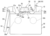
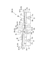
- FIG. 1 is a front view schematically showing a configuration of an optical fiber fusion splicer according to an embodiment of the present invention, and is a view showing a fusion splicer having a configuration in which covering clamps are arranged on both the left and right sides of a heat fusion part. .
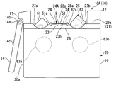
- BRIEF DESCRIPTION OF THE DRAWINGS It is a front view which shows roughly the structure of the optical fiber fusion splicer concerning one Embodiment of this invention, and a fiber holder is arrange
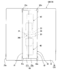
- FIG. 2 It is a top view which shows the optical fiber fusion splicer of FIG. 2 roughly, and is a figure which shows the state which closed the windshield cover. It is a top view which shows roughly the optical fiber fusion splicer of FIG. 2, and is a figure which shows the state which opened the windshield cover. It is a perspective view which shows roughly the specific example of the movable unit which attached the fiber mounting detector and the positioning pin to the movable stage of the optical fiber fusion splicer of FIG.
- FIG. 11 is a side view (right side view) illustrating a movable stage having a clamp in the optical fiber fusion splicer of FIG. 10. It is a figure explaining the movable stage which has the clamp of FIG. 11, Comprising: It is a top view of the position near the extension lever of a clamp upper member. It is a figure explaining the movable stage which has the clamp of FIG. 11, Comprising: It is a top view which shows the notch part vicinity of a clamp lower member. It is a figure which shows the windshield cover of the optical fiber fusion splicer of FIG.
- FIG. 16 is a plan view schematically showing the windshield cover of FIG. 15. It is a figure which shows the fixed cover member of the windshield cover of FIG. 14, FIG.
- FIG. 15 is the perspective view seen from the fixed cover main body side. It is a figure which shows the fixed cover member of the windshield cover of FIG. 14, FIG. 15, and is the perspective view seen from the inner side cover part side. It is a side sectional view (right sectional view) showing an example of a fusion splicer having a windshield cover composed of a rotating cover member and a slide cover member, and shows a state in which the rotating cover member and the slide cover member are closed together. Show. It is a sectional side view (right sectional view) which shows an example of the fusion splicer which has a windshield cover comprised by the rotation cover member and the slide cover member, and shows the state which opened the slide cover member with respect to the rotation cover member .
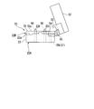
- FIG. 5 is a front view schematically illustrating an aspect of the optical fiber fusion splicer of FIG. 1 in which the detector main body of the fiber attachment detector is incorporated in the movable stage. It is another aspect of the optical fiber fusion splicer of FIG. 2, and is a front view schematically illustrating an aspect in which the detector main body of the fiber attachment detector is incorporated in the movable stage.
- FIG. It is a figure showing one example of a fusion splicer according to an embodiment of the present invention, and schematically illustrates a fusion splicer having a configuration in which covering clamps and finger detectors are provided on both the left and right sides of a heat-sealed part.
- FIG. It is a figure which shows an example of the fusion splicer which concerns on embodiment of this invention,
- the movable stage which functions as a holder mounting base which mounts a fiber holder on both the right and left sides of a heat-fusion part, and a finger detector It is a front view which shows roughly the fusion splicer of the structure provided.
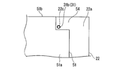
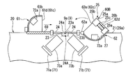
- FIG. 1 shows an example of the fusion splicer 10.
- a fusion splicer 10 (denoted by reference numeral 10A in the figure) shown in FIG. 1 is a device that fusion-connects a pair of optical fibers 9.
- reference numeral 91 is added to one of a pair of optical fibers 9 that are fusion-spliced by the fusion splicer 10A, and reference numeral 92 is added to the other.
- a coating material 9c (coating coating) made of synthetic resin is attached to the outer periphery of the optical fiber glass portion 9a (bare optical fiber), such as an optical fiber core wire or an optical fiber strand, An integrated coated optical fiber is used.
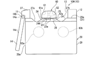
- this fusion splicer 10A has a pair of electrode rods 24 for heat-sealing the ends of optical fibers 91 and 92 on a device body 20 having an external appearance.
- a discharge portion 24a that is a region (space) between the tips of a pair of electrode rods 24 facing each other, a pair of movable stages 22 provided on both sides of the heat fusion portion 24A, and on each movable stage 22 It has a pair of covered clamps 50 attached, a pair of groove forming substrates 23 formed with positioning grooves 23 a used for positioning the optical fibers 91 and 92, and a windshield cover 60.
- the movable stage 22 functions as a clamp mounting base to which a covering clamp 50 (specifically, a clamp lower member 51 described later) is attached.
- the movable stage 22 can be moved in the left-right direction with respect to the apparatus main body 20 by the driving force of a power source (not shown) incorporated in the apparatus main body 20.
- the stage power source is preferably a power source that generates power by being driven by electromagnetic force.
- an electric motor, an electromagnet, a solenoid, or the like can be suitably used.
- the covering clamp 50 is provided so as to be openable and closable with respect to the lower clamp member 51 fixed on the movable stage 22 and the upper surface 51 a of the lower clamp member 51, and holds the optical fiber 9 between the lower clamp member 51. And a clamp upper member 52 to be fixed.
- a plate-like clamp lower member 51 fixed on the movable stage 22, and a clamp lower member 51 pivotally attached to the clamp lower member upper surface 51a can be opened and closed.
- a configuration in which the optical fiber 9 is gripped and fixed between the plate-like clamp upper member 52 provided on the plate and the like can be given.
- the upper clamp member 52 opens and closes with respect to the lower clamp member 51 by moving in the up-and-down direction with respect to the lower clamp member upper surface 51 a, and the optical fiber 9 between the upper clamp member 52 and the lower clamp member 51.
- a clamp capable of switching between gripping and releasing the grip can be employed.
- the covering clamp 50 grips and fixes the covering portion 9d between the lower clamp member 51 and the upper clamp member 52, which is a portion where the outer periphery of the optical fiber glass portion 9a of the optical fiber 9 is covered with the covering material 9c. .
- the optical fiber 9 is attached to the fusion splicer 10 ⁇ / b> A by being held and fixed by the covering clamp 50.
- the covering clamp 50 functions as a fiber attachment portion for attaching the optical fiber 9 to the fusion splicer 10A.
- the operator directly operates the clamp upper member 52 with fingers (manually) to open and close the clamp upper member 52 with respect to the lower clamp member 51. Yes.
- the covering clamp 50 has an upper member holding portion (not shown).
- the upper member holding unit holds the clamp upper member 52 in a state where the optical fiber 9 is gripped, and maintains the gripping and fixing state of the optical fiber 9.
- This upper member holding portion for example, a configuration in which the metal portion of the upper clamp member 52 is magnetically attracted by a permanent magnet incorporated in the lower clamp member 51, or a configuration using an engaging claw that can be manually engaged and released.
- a conventionally well-known structure is employable about the covering clamp of a fusion splicer.
- the clamp upper member 52 of the covering clamp 50 is opened with the windshield cover 60 opened as shown in FIGS.
- the optical fiber 9 (covering part 9d) is sandwiched between the lower clamp member 51 and the upper clamp member 52 by manually opening and closing.
- a fiber in which the covering material 9c at the tip thereof is previously removed to expose the optical fiber glass portion 9a is used as the optical fiber 9 to be gripped and fixed to the covering clamp 50.
- the optical fiber 9 is gripped and fixed to the covering clamp 50 so that a protruding portion 9b protruding from the covering clamp 50 toward the discharge portion 24a is secured.
- the groove forming substrate 23 of the fusion splicer 10A is provided one by one between the discharge part 24a and the movable stage 22 provided on both the left and right sides thereof.
- the optical fiber glass portion 9a from which the covering is removed at the protruding portion 9b protruding from the covering clamp is placed in the positioning groove 23a on the groove forming substrate 23.
- the tip of the optical fiber glass part 9a of each optical fiber 9 has a slight clearance therebetween.
- the optical fiber 9 is held and fixed to the covering clamp while adjusting the length of the protruding portion 9b from the covering clamp so as to be opposed to each other. Further, the length of the optical fiber glass portion 9a from which the coating has been removed is arranged at a position where the tips of the movable stage 22 can be fusion-bonded to each other when the movable stage 22 is advanced from the standby position to the advance limit position (described later). It has been adjusted in advance to be able to.
- the groove forming substrates 23 provided on both the left and right sides of the heat fusion part 24A are gripped and fixed to the covering clamp 50 and attached to the ends of a pair of optical fibers 91 and 92 (specifically, optical fiber glass) attached to the fusion splicer 10A.
- the positioning groove 23a serves to position the tip 9a on the same straight line (virtual straight line) in the horizontal direction of the fusion splicer with high accuracy.
- the positioning groove 23 a provided in the groove forming substrate 23 is a groove formed to be recessed with respect to the upper surface 23 b (substrate upper surface) of the groove forming substrate 23.
- the positioning groove 23a extends in the left-right direction of the connecting machine.
- the positioning groove 23a of the groove forming substrate 23 of the fusion splicer 10A of the illustrated example is a V-groove.
- the positioning groove 23a is not limited to the V groove as long as the optical fiber glass portion 9a exposed at the tip of the optical fiber 9 can be positioned with high accuracy.
- a round groove groove having a semicircular cross section
- a U groove a U groove
- a trapezoidal groove or the like can be employed.
- the groove forming substrate 23 of the fusion splicer 10A is usually made of ceramic in order to withstand the heat of discharge heating.
- the left and right groove forming substrates 23 are respectively fixed on the left and right optical fiber axis alignment mechanisms.
- the groove forming substrate 23 may be directly fixed to the upper surface 21 of the apparatus main body 20.
- the windshield cover 60 is a pair of cover members that are pivotally attached to the apparatus main body 20 via rotation shafts 61 a and 62 a provided along the upper surface 21 of the apparatus main body 20. 61, 62.
- the windshield cover 60 is opened and closed when the pair of cover members 61 and 62 rotate with respect to the apparatus main body 20.
- the first cover member 61 rotates with respect to the apparatus main body 20 by the driving force of the power source 63a incorporated in the apparatus main body.
- the second cover member 62 rotates independently of the first cover member 61 by the driving force of another power source 63b.
- the power sources 63a and 63b in the illustrated example are specifically electric motors.
- the power sources 63a and 63b that rotate and drive the cover members 61 and 62 with respect to the apparatus main body 20 are not limited to electric motors.
- the power sources 63a and 63b are preferably driven by electromagnetic force to generate power.
- an electromagnet, a solenoid, or the like can be employed.
- the movable stage 22 moves in the left-right direction of the splicer, so that the standby position (retreat limit position) and the movable stage 22 come into contact with the groove forming substrate 23 and the fiber clamp member 25. It is possible to move to the forward limit position.
- the covering clamp 50 fixedly attached to the movable stage 22 with the clamp lower member 51 is also moved together with the movable stage 22.
- the covering clamp 50 can move to the standby position (retreat limit position) and the advance limit position just before the movable stage 22 contacts the groove forming substrate 23 and the fiber clamp member 25 by the movement of the movable stage 22. Is possible.
- the operation of gripping and fixing the optical fiber 9 to the covering clamp 50 is performed in a state where the movable stage 22 is disposed at the standby position (position of the movable stage 22 shown in FIG. 1).
- this fusion splicer 10A after the optical fiber 9 is gripped and fixed to the covering clamps 50 on both the left and right sides of the heat fusion part 24A, the pair of movable stages 22 are moved from the standby position to the advance limit position. The tips of the optical fiber glass portions 9a of the optical fibers 91 and 92 can be brought into contact with each other.
- the fusion splicer 10A for example, power sources 63a and 63b (cover opening / closing power source) for driving the windshield cover 60 for generating power, and stage power different from the power sources 63a and 63b are used.
- the structure which provided the source in the apparatus main body 20 is employable, it is not limited to this.
- the fusion splicer 10A for example, a configuration in which the windshield opening / closing power sources 63a and 63b provided in the apparatus main body 20 also serve as left and right stage power sources can be employed.
- the lower clamp member 51 of the covering clamp 50 abuts against and contacts the upper surface 22a of the movable stage 22, and is attached to the movable stage 22 along the upper surface 22a.
- the upper surface 22a of the movable stage 22 in the illustrated example is formed to be inclined obliquely downward toward the discharge unit 24a from the side opposite to the side where the discharge unit 24a is provided in the left-right direction of the connecting machine.
- the lower clamp member 51 and the upper clamp member 52 that form the covering clamp 50 are plate-like, and are disposed along the movable stage upper surface 22a so as to be inclined downward toward the discharge portion 24a.
- the fusion splicer 10A grips and fixes the optical fiber 9 to the covering clamp 50, so that the optical fiber glass portion 9a at the tip of the protruding portion 9b of the optical fiber 9 from the covering clamp 50 is placed on the groove forming substrate 23. It can be placed so as to be pressed against the positioning groove 23a.
- the fusion splicer 10 ⁇ / b> A includes a detector 31 (detecting that the upper clamp member 52 that is open with respect to the lower clamp member 51 of the covering clamp 50 is closed by the lower clamp member 51.
- a clamp closing detector detecting that the upper clamp member 52 that is open with respect to the lower clamp member 51 of the covering clamp 50 is closed by the lower clamp member 51.
- the clamp closing detector 31 fiber mounting detector
- the sensor pin 31 b is provided so that its tip end (upper end) protrudes above the upper surface 51 a of the lower clamp member 51.
- the detector main body 31a of the clamp closing detector 31 is disposed below the movable stage 22 on both the left and right sides of the heating and fusing part 24A in order to avoid wiring to the movable part.
- the tip of the sensor pin 31 b (the sensor pin at the initial position) is located within a range in which the upper clamp member 52 that opens and closes relative to the lower clamp member 51 moves.
- the upper clamp member 52 of the covering clamp 50 can be opened with respect to the lower clamp member 51 to a position where it does not contact the tip of the sensor pin 31b.
- the optical fiber 9 is disposed on the upper surface 51a of the lower clamp member 51
- the upper clamp member 52 is opened with respect to the lower clamp member 51 and is not separated from the tip of the sensor pin 31b and does not contact the tip of the sensor pin 31b. Placed in position.
- opening the upper clamp member 52 relative to the lower clamp member 51 means opening the upper clamp member 52 at an opening angle of 90 degrees or more. It will be described as a state.
- an angle of 90 degrees or more with respect to the upper clamp member upper surface 51 a is maintained in order to maintain the upper clamp member 52 in its own weight.
- the structure which can be opened with is employable suitably.
- the tip of the sensor pin 31b (the upper end) is not in contact with the upper clamp member 52 that is open with respect to the lower clamp member 51, and is disposed at a position separated from the upper clamp member 52.
- the dimension which protrudes upward from the upper surface 51a of a lower member is set.
- the tip of the sensor pin 31b is disposed at a position where the clamp upper member 52 that has moved in the closing direction from the open state with respect to the clamp lower member 51 can come into contact with the upper end of the sensor pin 31b.
- the upper clamp member 52 presses the sensor pin 31b and pushes it into the detector main body 31a in the process of being opened and closed with respect to the lower clamp member 51.
- the fusion splicer 10A includes a windshield opening / closing power source 63a, 63b, a stage power source, and a drive control device that controls the driving of all other power sources provided in the fusion splicer, A detection signal acquired from the detector main body 31a is input to the drive control device.
- the detector main body 31a of the clamp closing detector 31 is the sensor pin 31b. Switching from the non-detection state to the detection state by pushing in. Therefore, in the fusion splicer 10A, the clamp upper member 52 that is open with respect to the clamp lower member 51 is changed from the non-detection to the detection when the detection signal acquired from the detector main body 31a is changed to the clamp lower member. It is detected by the drive control device that it is closed with respect to 51.
- the optical fiber 9 is held and fixed to the covering clamp 50 (the optical fiber is attached to the fusion splicer).
- the detection signal acquired from the detector body 31a of the clamp closing detector 31 transitions from no detection to detection. Accordingly, the drive control device detects that the holding and fixing of the optical fiber 9 by the covering clamp 50 has been completed.
- the clamp upper member 52 closed with respect to the clamp lower member 51 is opened with respect to the clamp lower member 51. Is detected by the drive control device.
- the type of the detection signal acquired from the detector main body 31a or the detection signal acquired from the detector main body 31a may be different between the detection state and the non-detection state.
- the specific configuration is not particularly limited.
- a non-detection output signal is output when in the non-detection state, and a detection output signal different from the non-detection output signal when in the detection state.
- An output device (device capable of acquiring different detection signals in the detection state and the non-detection state) can be given.
- a signal (output signal at the time of detection) is output only when it is in a detection state (a state in which no signal is output corresponds to “no detection signal detected”).
- a configuration in which a signal (output signal when no signal is detected) is output only when the signal is in the non-detection state (a state in which no signal is output corresponds to “detection signal is not detected”) can be employed.
- the configuration in which the presence or absence of signal output is switched between the detection state and the non-detection state described above is an example of a configuration in which detection signals acquired from the detector main body 31a are different from each other in the detection state and the non-detection state.
- the fusion splicer drive control device treats a state in which no signal is output as having acquired a detection signal indicating no detection. More specifically, as the detector body 31a, for example, the configuration in which the electric resistance or the output current value is switched between the detection state and the non-detection state, the electric circuit is opened in one of the detection state and the non-detection state, and the electric A configuration (switch) that closes the circuit, a configuration that outputs radio signals with different frequencies or optical signals with different wavelengths in the detection state and the non-detection state, and the like can be adopted.
- the detector body 31a for example, the configuration in which the electric resistance or the output current value is switched between the detection state and the non-detection state, the electric circuit is opened in one of the detection state and the non-detection state, and the electric A configuration (switch) that closes the circuit, a configuration that outputs radio signals with different frequencies or optical signals with different wavelengths in the detection state and the non-detection
- the optical fiber 9 (optical fiber glass portion 9a) placed on the positioning groove 23a of the groove forming substrate 23 is one cover. It is pressed toward the groove bottom of the positioning groove 23a by the pressing piece 25a provided at the tip of the fiber clamp member 25 attached to the inside of the member (second cover member denoted by reference numeral 62 in the illustrated example). Thereby, the optical fiber glass part 9a is positioned with high accuracy by the positioning groove 23a.
- the fiber clamp member 25 is provided only on one cover member (in the illustrated example, the second cover member 62), and is not provided on the first cover member 61.
- the fusion splicer has a windshield cover detector 33 that detects the open / closed state of the windshield cover 60 on the apparatus main body 20.
- the windshield cover detector 33 (cover member detector) detects the open / closed state of the pair of cover members 61, 62 of the windshield cover 60.
- One each is arranged at a position close to each of the rotation shafts 61a and 62a, and a total of two are provided.
- the windshield cover closing operation is completed when the two windshield cover detectors 33 detect that the pair of cover members 61 and 62 are disposed at the closed positions where they are closed to each other.
- the windshield cover detector 33 includes a detector main body 33a fixed to the upper part of the apparatus main body 20, and a sensor pin 33b protruding upward from the detector main body 33a.
- the sensor pin 33b can be pushed into the detector body 33a.
- the detector main bodies 33 a of the two windshield cover detectors 33 are provided at positions close to the rotation shafts 61 a and 62 a of the cover members 61 and 62 and fixed to the upper part of the apparatus main body 20.
- the detector main body 33 a of each windshield cover detector 33 is fixed to an area located between the rotation shafts 61 a and 62 a of the pair of cover members 61 and 62 in the upper part of the apparatus main body 20.
- the sensor pin 33b of each windshield cover detector 33 extends in the vertical direction at a position close to the rotation shafts 61a and 62a, and is provided between the rotation shafts 61a and 62a.
- the tip (upper end) of the sensor pin 33b of each windshield cover detector 33 is disposed above the rotation shafts 61a and 62a.
- the respective windshield cover detectors 33 When the windshield cover 60 is closed, the respective windshield cover detectors 33 have inner surfaces at positions close to the rotation shafts 61a and 62a in the main walls 61b and 62b (described later) whose arch sections are included in the cover members 61 and 62, respectively.
- the sensor pin 33b When the sensor pin 33b is pushed into the detector main body 33a by the projecting piece 60a protruding from the sensor, it is detected that the cover members 61 and 62 are disposed at the closed positions.
- the projecting piece 60a of the cover members 61 and 62 contacts the upper end of the sensor pin 33b and is pressed downward by the projecting piece 60a.
- the sensor pin 33b is pushed into the detector body 33a.
- the sensor pin 33b of the windshield cover detector 33 is arranged at a position where the cover member is closed with respect to the detector main body 33a by a spring provided on the detector main body 33a. Compared with the case where it has been done, it moves upward, and the dimension protruding upward from the detector main body 33a returns to before the pushing into the detector main body 33a by the protruding piece 60a of the cover member arranged at the closed position.
- the two windshield cover detectors 33 can individually detect the opening and closing of the pair of cover members 61 and 62 of the windshield cover 60.
- the windshield cover detector 33 is shown only in FIGS. 5 and 6 and is not shown in other drawings.
- the windshield cover detector may have any configuration that can detect the open / closed state of the windshield cover 60, and a known configuration that is used for detecting the open / closed state of the windshield cover of the fusion splicer can be appropriately employed.
- this windshield cover detector for example, it is detected in a non-contact manner that the windshield cover is closed (becomes a detection state), and one or more cover members constituting the windshield cover are moved from a closed position to an opened position. It is also possible to employ a magnetic sensor or the like that becomes a non-detection state when the windshield cover is not closed due to the displacement.
- each cover member of the windshield cover is provided with magnets or magnetic bodies, and the magnetic sensor detects changes in the magnetic field between when the windshield cover is closed and when the windshield cover is not closed.
- each cover member is provided with an energization circuit, and the current between the energization circuits due to contact or separation of the contact terminal portion provided in each energization circuit of each cover member is changed between the cover members.
- An energization sensor that detects opening and closing can also be used.
- an encoder or an angle sensor that measures a rotation angle of a portion (detection rotating portion) formed on or around the extension of the rotating shaft of the cover member can be employed.
- a rotation angle measuring sensor such as an encoder or an angle sensor
- the windshield cover detector is also installed in the open position in order to detect that the cover member has been placed in the predetermined open position. Also good.
- the windshield cover closing operation is provided on the left and right sides of the heat-sealing part 24A in a state where the windshield cover is open, that is, in a state where the windshield cover detector 33 detects that the windshield cover is open.
- both detector bodies 31a of the clamp closing detector 31 are switched from non-detection to detection, and both detection signals acquired from both detector bodies 31a are detected by the drive control device, or both are detected. This is automatically started when a preset waiting time (for example, several seconds) has elapsed since both detection signals from the device main body 31a are detected.
- This fusion splicer 10A is triggered when the detection signals acquired from the detector main body 31a of the clamp closing detector 31 in the drive control device both transition from a non-detection state to a detection state. As a signal, fiber fusion and inspection operations (described later) are started.
- the windshield cover 60 is closed at the moment when both detection signals from the detectors 31 provided on the left and right sides of the heat-fused portion 24A are detected. Compared to the case, it is possible to reduce the possibility that the hand is caught in the windshield cover.
- the setting of this waiting time can be changed by the user with software.
- a warning message can be displayed on the monitor device, a lamp such as an LED blinks, an alarm sound can be output, etc., to alert the windshield cover to be closed.
- the fusion splicer 10A automatically performs an inspection operation before connecting the optical fiber after the windshield cover closing operation is completed, and then optical fibers 91 and 92 (specifically, optical fibers exposed at their tips).
- the fusion splicing operation for fusion splicing the glass portion 9a) is automatically performed. Further, the fusion splicer 10A automatically executes the connection portion inspection operation after the fusion splicing operation is completed.
- the movable stage 22 provided on both the left and right sides of the heat-sealing part 24A is advanced from the standby position toward the discharge part 24a, and the movable stage 22 is moved to the standby position and the advance limit position.
- tip part of the optical fibers 91 and 92 is imaged with the camera 71 (refer FIG. 5) incorporated in the apparatus main body 20, The captured image is analyzed with an image processing apparatus, The optical fiber glass part 9a of the optical fibers 91 and 92 is obtained. The end face angle or end face state of the tip is automatically calculated.
- the amount of axial misalignment between the pair of optical fibers is also calculated. If there is an abnormality in the calculation result, the fusion splicer issues an alarm to the operator. On the other hand, when the calculation result is normal, there is no alarm and the operator automatically shifts to the next fusion splicing operation without performing the operation for completing the inspection. However, when the operator visually inspects the end face state, the captured image is displayed on the monitor device 14 (see FIG. 3), and the optical fibers 91 and 92 of the optical fibers 91 and 92 are displayed from the captured image displayed on the monitor device 14. An operator determines whether the end face state of the tip of the optical fiber glass portion 9a is good or bad.
- the inspection is terminated by the operator pressing the pre-connection inspection end button (not shown) provided on the fusion splicer (for example, the switch base 11).
- the pre-connection inspection end command input unit provided in the fusion splicer is operated by the operator to finish the pre-optical fiber connection inspection operation. Not limited to buttons.
- the pre-connection inspection end command input unit may be, for example, a dial switch that can be manually rotated, or an inspection end button displayed on the monitor device 14.
- the fusion splicer 10A proceeds to the fusion splicing operation after the inspection operation before the optical fiber connection is completed.
- a voltage is applied between the pair of electrode rods 24 to start discharging, and the movable stage 22 provided on both the left and right sides of the heat fusion portion 24A is moved from the pre-connection inspection position to the advance limit position.
- the optical fibers 91 and 92 that are held and fixed to the left and right coating clamps 50 are fused while being brought close to each other. Connecting.
- connection portion inspection operation as shown in FIG. 5, the fusion spliced portion is imaged by a camera 71 incorporated in the apparatus main body 20, the captured image is analyzed by an image processing device, and the connected optical fibers 91 and 92 are connected. Connection loss is automatically calculated and connection status abnormality is automatically determined. If there is an abnormality in the calculation result, the fusion splicer issues an alarm to the operator. On the other hand, when the calculation result is normal, there is no alarm and the operator automatically shifts to the next step without performing the operation for completing the inspection. However, when the operator visually inspects the connection portion, the captured image is displayed on the monitor device 14 (see FIG. 3).
- connection portion inspection operation the image captured by the camera 71 is continuously displayed until a subsequent operation (connection portion tensile inspection or removal of the optical fiber from the fusion splicer) is performed on the monitor device 14.
- the fusion splicer 10A drives the windshield opening / closing power sources 63a and 63b to open the windshield cover 60 after the connection portion inspection operation is completed. The opening operation and the connection part tensile inspection are performed automatically.
- the fusion splicer 10A moves the stage pressing member 81 moved forward and backward toward the discharge part 24a by the power of the stage power source (not shown) to the left and right of the heat fusion part 24A.
- Each stage pressing member 81 is moved forward and backward toward the discharge unit 24a when the pressing member moving mechanisms 82 provided on the left and right sides of the heat-sealing portion 24A are driven by the power of the stage power source.
- the fusion splicer 10A advances the movable stage 22 by pressing the movable stage 22 from the side opposite to the side where the advance limit position is arranged by the stage pressing member 81 advanced toward the discharge part 24a.
- the fusion splicer 10A includes a spring 83 (hereinafter referred to as a stage) that elastically urges the pair of movable stages 22 between the pair of movable stages 22 provided on the left and right sides of the heat fusion part 24A. It is also called an urging spring (the illustrated example has a compression coil spring.).
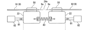
- FIG. 25A shows a state when gripping and fixing of the optical fiber 9 is completed in the covering clamps 50 provided on both the left and right sides of the heat-sealing part 24A.
- the movable stages 22 on both the left and right sides are pressed by the stage pressing member 81 by the elastic biasing force of the stage biasing spring 83 and are respectively disposed at the standby positions.
- the position where the stage pressing member 81 is disposed is also referred to as a pressing member standby position.
- the movable stage 22 provided on both the left and right sides of the heat fusion part 24A is pressed by a stage pressing member 81 that has advanced from the pressing member standby position.
- the movable stage 22 advances from the standby position toward the advance limit position while pressing and contracting the stage biasing spring 83. Then, the movable stage 22 reaches the state shown in FIG. 25B through the inspection operation before the optical fiber connection and the fusion splicing operation.
- FIG. 25B shows a state where the fusion splicing operation has been completed.
- the optical fibers 91 and 92 are fusion spliced to the optical fiber glass portion 9a at the fusion splicing portion 9f.
- the connection portion inspection operation after the fusion splicing operation, the position of the stage pressing member 81 when the fusion splicing operation is completed is kept, and the position of the movable stage 22 when the fusion splicing operation is completed. Is executed while being preserved.
- the stage pressing member 81 is moved (retracted) toward the pressing member standby position by driving the pressing member moving mechanism 82, as shown in FIG.
- a tensile load is applied to the fusion splicing portion 9 f by the elastic biasing force of the stage biasing spring 83.
- the stage pressing member 81 is disposed at the pressing member standby position.
- the stage pressing member is retracted to be separated from the movable stage 22, and only the elastic urging force of the stage urging spring is applied to the fusion connection portion 9f as a tensile load.
- the start timing of the connection portion tensile inspection can be set regardless of the start of the windshield cover opening operation.
- inspection can be set irrespective of the timing which a windshield cover open
- the connection portion tensile inspection may be completed before the start of the windshield cover opening operation, or may be completed after the opening operation is completed.
- an inspection completion notification operation for notifying the operator of the completion of the connecting part tensile inspection by outputting an alarm sound, lighting a lamp, displaying on a monitor device, etc. May be performed. If the operator is notified of the completion of the inspection in a state where the windshield cover opening operation is completed, or if the windshield cover opening operation is completed after the inspection completion notification is performed, the upper clamp member 52 of the covering clamp 50 is provided. Are opened with respect to the lower clamp member 51, and the optical fibers 91 and 92 held and fixed to the covering clamp 50 are taken out together with the fusion splicing portion 9f (fiber take-out operation).
- the windshield cover opening operation is performed in advance by a predetermined waiting time after notifying the execution of the windshield cover opening operation, for example, by outputting an alarm sound, lighting a lamp, displaying a warning message on the monitor device, etc. It is preferable to execute when elapses. Thereby, for example, it is possible to avoid pinching fingers between the cover member constituting the windshield cover 60 and the apparatus main body 20.
- the movable stages 22 provided on the left and right sides of the heat fusion part 24A are finally arranged at the standby position by the elastic biasing force of the stage biasing spring 83 after the completion of the fiber take-out operation by the operator.
- the movable stage 22 is placed in the standby position by being pressed against the stage pressing member 81 from the side where the discharge portion 24 a is provided by the elastic biasing force of the stage biasing spring 83.
- the state of the fusion splicer 10A at this time is also referred to as a fiber set standby state.
- the operation standby initial state when the power switch (not shown) is turned from the on state to the off state, the movable stage 22 is disposed at the standby position and the windshield cover 60 is closed (hereinafter, the operation standby initial state). Also called).
- the fusion splicer 10A in the initial operation standby state turns on the power switch that has been in the OFF state, thereby opening the windshield cover 60 and entering the fiber set standby state.
- the fusion splicer 10A in the fiber set standby state uses the clamp upper member 52 of the cover clamp 50 provided on the left and right sides of the heat fusion part 24A as a clamp lower member in order to grip and fix the optical fiber 9 to the cover clamp 50.
- both detection signals are changed from non-detection to detection, the windshield cover closing operation is performed.
- the operation of the fusion splicer 10A after the completion of the windshield cover closing operation, the subsequent windshield cover opening operation, and the connection portion tensile inspection until the fiber set standby state is reached is also referred to as a fiber fusion / inspection operation.
- the fusion splicer 10A closes the clamp upper members 52 of the covering clamps 50 on both the left and right sides from the open state with respect to the clamp lower member 51 in the fiber set standby state.
- the fusion splicer 10A in the initial state of operation standby is turned off in the initial state of operation standby by operating the power switch to switch from the on state to the off state.
- the fusion splicer 10A may be configured such that the inspection completion notification operation is not performed.
- the fusion splicer 10A does not perform the inspection completion notification operation when the connection portion tensile inspection is completed at the same time or before the completion of the opening operation of the windshield cover, and after the completion of the windshield cover opening operation, An operator may perform fiber extraction work. Further, the fusion splicer 10A, for example, does not perform the inspection completion notification operation and completes the connection from the completion of the windshield cover opening operation when the connection portion tensile inspection is completed when a predetermined time elapses after the windshield cover opening operation is completed. After the partial tensile inspection is completed, the operator may perform the fiber extraction operation.
- the fusion splicer 10 ⁇ / b> A is provided on both the left and right sides of the heat fusion part 24 ⁇ / b> A by driving (moving) the stage pressing member 81 or the elastic biasing force of the stage biasing spring 83 after completion of the fiber take-out operation by the operator.
- the movable stage 22 is finally arranged at the standby position. Further, the pressing member contact portion of the movable stage 22 is brought into contact with the stage pressing member 81 by the elastic biasing force of the stage biasing spring 83.
- the state of the fusion splicer 10A at this time is also referred to as a fiber set standby state.
- the fusion splicer 10A when a power switch (not shown) is turned from an on state to an off state, the movable stage 22 is disposed at the standby position and the windshield cover 60 is closed (hereinafter, the operation standby initial state). Also called).
- the fusion splicer 10A in the initial operation standby state turns on the power switch that has been in the OFF state, thereby opening the windshield cover 60 and entering the fiber set standby state.
- the fusion splicer 10A in the fiber set standby state clamps the clamp upper members 52 of the coating clamp 50 provided on the left and right sides of the heat-sealing part 24A in order to grip and fix the optical fiber 9 to the coating clamp 50.
- the detectors of the pair of clamp close detectors 31 provided on both the left and right sides of the heat-fused portion 24A.
- the windshield cover closing operation is performed.
- the operation of the fusion splicer 10A after the completion of the windshield cover closing operation, the subsequent windshield cover opening operation, and the connection portion tensile inspection until the fiber set standby state is reached is also referred to as a fiber fusion / inspection operation.
- the fusion splicer 10A when performing fusion splicing of the optical fiber 9, the clamp upper member 52 of the covering clamp 50 provided on both the left and right sides of the heat fusion portion 24A is clamped in the fiber set standby state.
- the optical fiber 9 is held and fixed, and the fiber fusion / inspection operation is automatically executed.
- the fusion splicer 10A in the fiber set standby state enters the operation standby initial state by operating the power switch that has been in the on state to turn it off.
- the covering clamp 50 provided in the fusion splicer 10A is detachable from the movable stage 22.
- the movable stage 22 provided in the fusion splicer 10 can place the fiber holder 40 on which the optical fiber 9 is held and fixed with the covering clamp 50 removed. That is, the movable stage 22 can use the upper part as a holder mounting part.
- a configuration in which the movable stage 22 is dedicated to the attachment of the covering clamp 50 and is not used as a holder placement portion on which the fiber holder 40 is placed can be employed as the fusion splicer according to the embodiment of the present invention.
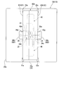
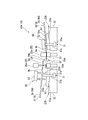
- FIG. 2 shows a fusion splicer 10 according to a second embodiment of the present invention, in which the covering clamp 50 provided on the movable stage 22 of the fusion splicer 10A illustrated in FIG. 22 shows a configuration in which 22 is used as a holder mounting portion on which the fiber holder 40 holding and fixing the optical fiber 9 is mounted.
- Reference numeral 10B is added to the fusion splicer 10 of FIG. 2 according to the second embodiment of the present invention.
- the fiber holder 40 is placed on the movable stage 22 and is detachable from the movable stage 22.
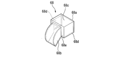
- the fiber holder 40 is held and fixed by sandwiching the optical fiber 9 between a base plate 41 and a lid plate 42 that is pivotally attached to the base plate 41 and can be opened and closed.
- the optical fiber 9 is held and placed on the movable stage 22 provided in the fusion splicer 10B.
- the fiber holder 40 illustrated in FIGS. 2 and 9 has a configuration in which a lid plate 42 is pivotally attached to one end portion in the longitudinal direction of a rectangular plate-like base plate 41.
- the lid plate 42 can be opened and closed with respect to a base plate upper surface 41a which is a surface on one side of the base plate 41 in the thickness direction.
- the cover plate 42 has a rotating shaft 43 provided along the longitudinal direction of the base plate 41 at one end in the width direction (left and right direction in FIG. 8) of the rectangular plate-shaped base plate 41. It is pivotally attached to the base plate 41 via.
- the optical fiber 9 is fixed to the fiber holder 40 so that a protruding portion 9 e whose front end is protruded from the fiber holder 40 is secured. Further, the optical fiber 9 held and fixed to the fiber holder 40 removes the coating on the tip of the protruding portion 9e to expose the optical fiber glass portion 9a (bare optical fiber). The fiber holder 40 holds and fixes the covering portion 9d of the optical fiber 9 between the base plate 41 and the lid plate 42.
- the optical fiber 9 is held with the windshield cover 60 opened (for example, see FIG. 4).
- the fixed fiber holder 40 is placed on the movable stage 22. That is, the fiber holders 40 that hold and fix the optical fibers 9 are placed on the pair of movable stages 22, respectively.
- the optical fiber 9 is mounted on the fusion splicer 10 ⁇ / b> B by placing the fiber holder 40 on which the optical fiber 9 is held and fixed on the movable stage 22.
- the movable stage 22 functions as a fiber mounting portion for mounting the optical fiber 9 on the fusion splicer 10B.
- this fusion splicer 10B when the fiber holder 40 holding and fixing the optical fiber 9 is placed on the movable stage 22 provided on both the left and right sides of the heat fusion part 24A, the fiber holder An optical fiber of the optical fiber 9 in which the optical fiber glass part 9 a from which the coating has been removed is placed in the positioning groove 23 a on the groove forming substrate 23 and is held by the fiber holder 40 in the protruding part 9 e protruding from 40.
- the length of the protruding portion 9e protruding from the fiber holder 40 and the length of the coating of the optical fiber glass portion 9a at the tip are removed so that the tip of the glass portion 9a is opposed to each other with a slight gap.
- the length of the coating on the optical fiber glass portion 9a is removed so that the front ends of the movable stage 22 can be fusion-connected to each other before the movable stage 22 is advanced from the standby position and reaches the advance limit position. It has been adjusted in advance so that it can be placed in.
- the placement of the fiber holder 40 holding and fixing the optical fiber 9 on the movable stage 22 is performed in a state where the movable stage 22 is disposed at the standby position (position of the movable stage 22 shown in FIGS. 1 and 2).
- the fiber holder 40 to which the optical fiber 9 is held and fixed has a surface opposite to the surface on which the cover plate 42 is provided on the base plate 41 provided so that the horizontal direction of the connecting machine is the longitudinal direction, and the movable stage 22.
- the fiber holder 40 is placed on the movable stage 22 by placing the base plate 41 on the upper surface 22a of the movable stage 22 so as to be in contact with the upper surface 22a.
- the upper surface 22a of the movable stage 22 can be used as a holder placement surface for placing the fiber holder 40 (specifically, the base plate 41).
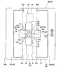
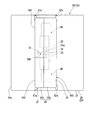
- FIG. 9 shows a specific example of the movable stage 22.
- the movable stage 22 is formed in a plate shape.
- 9 shows two movable positioning pins 22b projecting on the movable stage upper surface 22a and a detector 32 (holder for detecting that the fiber holder 40 is placed on the movable stage upper surface 22a.
- a movable unit 22A having a configuration in which a mounting detector) is attached is shown.
- the positioning pins 22b provided on the movable unit 22A are shown only in FIGS. 9 and 11, and are not shown in drawings other than FIGS.
- the fiber holder 40 when the fiber holder 40 is placed on the movable stage 22, the two positioning pins 22 b are inserted into pin fitting holes 41 b formed at two locations on the base plate 41 of the fiber holder 40.
- the fiber holder 40 functions to stably maintain the state where the fiber holder 40 is placed at a predetermined position on the movable stage 22 in a predetermined direction.
- pin fitting holes 41 b are formed at two locations on the base plate 41.
- the fiber holder 40 illustrated in FIG. 9 illustrates a configuration in which the pin fitting hole 41b is a through hole that penetrates the base plate 41 in the thickness direction.
- the pin fitting hole 41b the lower surface of the base plate 41 opposite to the upper surface 41a of the base plate is opened and the positioning pin 22b protruding on the movable stage 22 is accommodated.
- Any configuration may be employed as long as the 40 base plates 41 can come into contact with and contact with the upper surface 22a of the movable stage 22.
- the pin fitting hole 41b may be a non-through hole that does not open on the base plate upper surface 41a.
- the two positioning pins 22b of the movable unit 22A can be inserted into and removed from the two pin fitting holes 41b of the base plate 41. Therefore, the fiber holder 40 placed on the movable stage 22 by inserting and fitting the two positioning pins 22b of the movable unit 22A into the two pin fitting holes 41b of the base plate 41 is connected to the movable unit 22A. It can be removed from the movable stage 22 by moving upward along the two positioning pins 22b with respect to the movable stage 22.
- the holder placement detector 32 will be described. As shown in FIG. 2, the detector 32 is arranged with the tip of the sensor pin 31b of the clamp closing detector 31 of the fusion splicer 10A illustrated in FIG. 1 slightly protruding from the movable stage upper surface 22a. Except for the position of the tip of the sensor pin 31b, the configuration is the same as that of the clamp closing detector 31 described above. Similarly to the clamp closing detector 31, the holder placement detector 32 (fiber attachment detector) will be described with reference numeral 31 a in the figure attached to the detector body and reference numeral 31 b in the figure attached to the sensor pin.
- the fusion splicer 10B is used only in that the movable stage 22 is used as a holder mounting portion and the holder mounting detector 32 is used instead of the clamp closing detector 31 in FIG. It is different from the fusion splicer 10A, and for example, the relationship between the detector 32 and the drive control device other than these differences is the same as that of the fusion splicer 10A in FIG.
- the detector 32 includes a detector main body 31a fixed to the lower side of the movable stage 22, and a sensor pin 31b protruding upward from the detector main body 31a.
- the sensor pin 31b is inserted into an upper and lower through hole 22c that penetrates the movable stage 22 up and down, and a tip end portion (upper end portion) protrudes from the movable stage upper surface 22a.
- the position of the sensor pin 31b of the detector 32 at this time is the initial position.
- the upper ends of the upper and lower through holes 22c are open to the movable stage upper surface 22a.
- the detector main body 31a is in a non-detection state.
- the holder placement detector 32 places the fiber holder 40 on the movable stage 22, the sensor pin 31b pressed by the base plate 41 lowered from above the movable stage 22 is pushed into the detector body 31a.
- the holder mounting detector 32 is acquired from the detector main body 31a, when the base plate 41 contacts and touches the movable stage 22, and the detector main body 31a switches from a non-detection state to a detection state.
- Each detected signal transitions from no detection to detection.
- both detection signals acquired from the detector main body 31a of the holder placement detector 32 provided on the left and right sides of the heat fusion part 24A both change from non-detection to detection. By detecting both, it can be detected that the fiber holder 40 is placed on the movable stage 22.
- each detection signal acquired from detector main part 31a changes from detection to non-detection.
- the detection signals acquired from the detector main bodies 31a provided on the left and right sides of the heat fusion part 24A both change from detection to non-detection, so that both become non-detection. Thereby, it can be detected that the fiber holder 40 placed on the movable stage 22 has been removed.
- the fusion splicer 10B When the fusion splicer 10B is in a fiber set standby state as in the fusion splicer 10A described above, the optical fiber 9 is placed on the movable stage 22 provided on both the left and right sides of the heat fusion splicer 24A.
- the windshield cover closing operation is automatically executed. After the windshield cover closing operation, the fusion splicer 10B automatically executes the fiber fusion / inspection operation in the same manner as the fusion splicer 10A described above.
- the windshield cover closing operation of the fusion splicer 10B is such that both the detector main bodies 31a provided on the left and right sides of the heat fusion part 24A are switched from non-detection to detection, and both the detector main bodies 31a are detected by the drive control device.
- both of the detection signals acquired from the above are detected, it is automatically started at that time or when a preset waiting time (for example, several seconds) elapses from that time.
- a preset waiting time for example, several seconds
- both detection signals acquired from the detector main bodies 31a provided on the left and right sides of the heat fusion part 24A by the drive control device are changed from a non-detection state to a detection state. When the transition is made, this serves as a trigger signal to automatically start the fiber fusion / inspection operation.
- the fiber take-out operation can be performed by opening the cover plate 42 of the fiber holder 40 instead of the covering clamp 50.
- the operator performs holder removal work for removing the fiber holders 40 from the movable stage 22 respectively.
- the fusion splicer 10B performs the fiber fusion / inspection operation, so that the windshield cover 60 and the movable stage 22 provided on both the left and right sides of the heat fusion part 24A are finally connected to the fusion splicer 10A.
- the fiber set is in a standby state, that is, the windshield cover 60 is opened, and the movable stage 22 provided on both the left and right sides of the heat-sealing part 24A is in the standby position.
- the covering clamp 50 provided on the movable stage 22 is omitted, and the movable stage 22 is placed on the holder mounting portion. Only the point of using the holder mounting detector 32 instead of the clamp closing detector 31 is different from the fusion splicer 10A, and the other configuration is the same as the fusion splicer 10A described above.
- the fusion splicer 10B enters a fiber set standby state, similar to the fusion splicer 10A, when a power switch (not shown) is turned from an off state to an on state.
- the fusion splicer 10B in the fiber set standby state enters the operation standby initial state by operating the power switch from the on state to the off state, and the power is turned off.
- the pair of cover members 61 and 62 are independently driven to rotate, but the speed is rotationally driven at the same constant speed.
- the windshield cover closing operation of the fusion splicer 10 is not limited to this. In the windshield cover closing operation, for example, it is possible to drive only the second cover member 62 to which the fiber clamp member 25 is connected to start closing at a higher speed and to drive the closing end at a slower speed than the start of closing. is there.
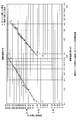
- the moving speed of the fiber clamp member 25 accompanying the rotation of the second cover member 62 is approximately 50 cm / s at the beginning of the closing of the second cover member 62. And securing a closing end section that moves at a speed of approximately 1 cm / s.
- a closing end section where the fiber clamp member 25 is driven at a speed (for example, approximately 1 cm / s) slower than the speed at which the fiber clamp member 25 starts to close. This effectively contributes to suppressing (or eliminating) vibration generated when the members are closed.
- the closing start of the second cover member 62 to which the fiber clamp member 25 is coupled is driven at a higher speed, and the closing end is slower than the closing start.
- the descending speed of the fiber clamp member 25 is reduced, and damage to the optical fiber can be reduced without providing a special mechanism.
- the movable unit 22A illustrated in FIG. 9 can attach the covering clamp 50 to the movable stage 22 so as to be detachable.
- 11, 12A, and 12B show an example of a movable stage 22B with a clamp in which a covering clamp 50 is attached on the movable stage 22 of the movable unit 22A.
- FIG. 10 is a fusion splicer in which the movable stage 22B with a clamp is assembled by attaching the covering clamp 50 on the movable stage 22 of the movable unit 22A provided on both the left and right sides of the heat fusion part 24A in FIG. An example of 10B is shown.
- the pin fitting which can insert and fit the positioning pin 22b of the movable unit 22A from the lower side of the lower clamp member 51 into two places of the lower clamp member 51 constituting the covering clamp 50.
- a joint hole 56 is formed.
- the covering clamp 50 can be mounted on the movable stage 22 by inserting the positioning pins 22b of the movable unit 22A into the two pin fitting holes 56 of the lower clamp member 51 and fitting them.
- the covering clamp 50 can be attached to and detached from the movable stage 22 by sliding the clamp lower member 51 along the positioning pins 22b inserted into the two pin fitting holes 56 and fitted.
- the pin fitting hole 56 of the lower clamp member 51 that constitutes the covering clamp 50 in the illustrated example is a through hole that penetrates the thickness of the plate-like lower clamp member 51.
- the pin fitting hole 56 the positioning pin 22b protruding on the movable stage 22 is accommodated in an insertable / removable manner from an opening opening on the lower surface which is the surface opposite to the upper surface 51a of the lower clamp member 51.
- any configuration may be used as long as the lower clamp member 51 can be placed in contact with the upper surface 22 a of the movable stage 22.
- the pin fitting hole 56 may be a non-through hole that does not open in the lower clamp member upper surface 51a.
- an extension lever 53 that protrudes from the upper clamp member 52 to the lower clamp member 51 is attached to the upper clamp member 52 of the covering clamp 50. Yes.
- the extension lever 53 closes the clamp upper member 52 in an open state with respect to the clamp lower member 51 of the covering clamp 50 with respect to the clamp lower member 51
- the sensor pin 31b of the detector 32 is caused to protrude from the detector main body by the protruding end. It is pressed toward 31a.
- the push detector main body 31a is switched from the non-detection state to the detection state when the sensor pin 31b is pushed into the detector main body 31a.
- the upper clamp member 52 is opened with respect to the lower clamp member 51 so as not to come into contact with the tip of the sensor pin 31b at the initial position, and is disposed at a position separated from the tip of the sensor pin 31b.
- the lower clamp member 51 that constitutes the movable stage 22B with a clamp is cut so that the tip (upper end) of the sensor pin 31b that protrudes from the movable stage 22 is exposed.
- a notch 54 is formed.
- This notch 54 is a concave shape that is recessed from the end surface 51 b (end surface on the rotating shaft 55 side) of the lower clamp member 51 at a position close to the rotating shaft 55 that pivotally attaches the upper clamp member 52 to the lower clamp member 51. Is formed.
- the extension lever 53 is inserted into the notch portion 54 of the lower clamp member 51 when the upper clamp member 52 is closed to the lower clamp member 51 so that the tip of the sensor pin 31b can be pressed downward.
- the member 52 is provided so as to protrude to the rotating shaft 55 side. With this configuration, the extension lever 53 protruding from the upper clamp member 52 is inserted into the optical fiber 9 between the lower clamp member 51 and the upper clamp member 52 that is open with respect to the lower clamp member 51. It is hard to become an obstacle.
- the movable unit 22A changes the design of the detector 32 and the installation position of the movable unit 22A with respect to the movable stage 22 even when the covering clamp 50 is attached on the movable stage 22 or when the movable stage 22 is used as a holder mounting portion. Without using it.
- the detector 32 of the movable unit 22A can be used as a clamp closing detector when the movable stage 22B with a clamp is used, and the movable stage 22 is used as a holder mounting portion without attaching the covering clamp 50. In this case, it can be used as a holder placement detector.
- a positioning groove 23 a on the groove forming substrate 23 is formed inside one of the pair of cover members 61 and 62 (second cover member 62 in the illustrated example) constituting the windshield cover 60.
- a fiber clamp member 25 is attached to press the optical fiber glass portion 9a, which is the tip of the optical fiber 9 placed, from above toward the groove bottom of the positioning groove 23a.
- the fiber clamp member 25 allows the optical fiber glass portion 9a provided at the distal end portion of the optical fiber 9 placed in the positioning groove 23a to be inserted into the positioning groove 23a from above. It is pressed toward the groove bottom substrate 23 by pressing toward the groove bottom.
- the cover member 61 without the fiber clamp member 25 is referred to as the first cover member
- the cover member 62 with the fiber clamp member 25 is referred to as the first. It is also called 2 cover member.
- the windshield cover 60 includes a pair of electrode rods 24, a discharge portion 24 a, and grooves provided on the left and right sides of the discharge portion 24 a by closing the pair of cover members 61 and 62. It is configured in a container shape that accommodates and covers the formation substrate 23, the fiber clamp member 25, and the fiber holders 40 placed on the movable stage 22 provided on the left and right sides of the discharge part 24a.
- the windshield cover 60 in the closed state as shown in FIGS. 5 and 7 prevents the outside wind from entering the inside of the windshield cover 60, and the wind does not affect the fusion splicing of the optical fiber 9 in the discharge portion 24a. Like that.
- the pair of cover members 61 and 62 are formed in an elongated shape extending in the left-right direction of the connecting machine.
- the pair of cover members 61 and 62 are provided at two places in the front-rear direction of the apparatus main body 20.
- the windshield cover 60 has a half structure constituted by a pair of front and rear cover members 61 and 62.
- the windshield cover 60 in the closed state as shown in FIGS. 5 and 7 is divided into two members in the front-rear direction (left-right direction in FIGS. 5 and 7) from the center part, that is, from the center part in the front-rear direction. It is divided into a first cover member 61 on the front side and a second cover member 62 on the rear side.
- a boundary surface 67 of a pair of cover members 61 and 62 that are closed to each other is present at the center in the front-rear direction of the windshield cover 60 in the closed state. In the illustrated windshield cover 60, the boundary surface 67 extends along a virtual vertical plane perpendicular to the front-rear direction.
- the cover main wall 64 extending in the left-right direction of the connecting machine has an arched cross section, and the cover main wall 64 extends.
- the cover end wall portion 65 has a surface projecting perpendicularly to the direction in which the cover main wall portion 64 extends at both ends in the direction in which the cover main wall 64 extends.
- the cover end wall portions 65 provided at both ends in the direction in which the cover main wall portion 64 extends are concave portions that are groove-shaped regions along the cover main wall portion 64 on the inner peripheral side of the cover main wall portion 64 having an arcuate cross section. Both ends in the extending direction of the groove 66 are closed.
- the first cover member 61 has a main wall portion 61b extending in an arch shape in cross section, and surfaces projecting perpendicularly to the extending direction of the main wall portion 61b at both ends in the direction in which the main wall portion 61b extends. And an end wall portion 61c.
- the second cover member 62 has a main wall portion 62b extending in an arched cross section, and surfaces projecting perpendicularly to the extending direction of the main wall portion 62b at both ends in the direction in which the main wall portion 62b extends.
- an end wall portion 62c having
- the pair of cover members 61 and 62 are connected to one end face and the end through the center of the cross section of the main walls 61b and 62b having an arched cross section.
- the end surfaces of the wall portions 61c and 62c are closed.
- Each of the cover members 61 and 62 has closed end surfaces 61d and 62d that are closed together to form a boundary surface 67 when the windshield cover 60 is closed.
- the main wall portions 61b and 62b of the cover members 61 and 62 constitute the cover main wall portion 64, and the end wall portions 61c and 62c of the cover members 61 and 62 cover the cover.
- An end wall portion 65 is configured.
- each cover member 61, 62 has main body contact surfaces 61 e, 62 e that are virtual surfaces in contact with the upper surface 21 of the apparatus main body when the windshield cover 60 is closed.
- the cover members 61 and 62 are pivoted to the apparatus main body 20 via the rotation shafts 61a and 62a, respectively, on the side (end portion) opposite to the closing end faces (end portions) 61d and 62d of the main wall portions 61b and 62b. It is worn.
- Each of the cover members 61 and 62 is a rotation cover member that is rotatably attached to the apparatus main body 20 via the rotation shafts 61a and 62a.
- the rotation shafts 61a and 62a of the cover members 61 and 62 are provided at positions displaced from the discharge part 24a in the front-rear direction of the connecting device.
- the cover members 61 and 62 are pivotally attached to the apparatus main body 20 by rotation shafts 61a and 62a so as to be rotatable about the rotation axis in the left-right direction of the connecting machine.
- the rotating shafts 61 a and 62 a are attached to the apparatus main body 20 along the upper surface 21.
- the rotation axes of the cover members 61 and 62 with respect to the apparatus main body 20 are positioned so as to coincide with the apparatus main body upper surface 21 or slightly deviate from the apparatus main body upper surface 21 in the vertical direction of the connecting machine (vertical direction in FIG. 5). .
- the cover members 61 and 62 are configured such that the main body contact surfaces 61 e and 62 e are between the boundary surface 67 and the rotation shafts 61 a and 62 a in a state where the windshield cover 60 is closed. It contacts the upper surface 21 of the apparatus main body.
- the cover members 61 and 62 are positioned between the rotation shafts 61a and 62a and the boundary surface 67 in the front-rear direction of the connecting machine.
- the pair of cover members 61 and 62 constituting the windshield cover 60 are formed in an elongated shape extending along the left-right direction of the connecting machine.
- the fiber clamp members 25 are provided at two locations in the longitudinal direction of the second cover member 62.
- the two fiber clamp members 25 are provided at positions corresponding to the groove forming substrates 23 provided on both the left and right sides of the discharge part 24a when the pair of cover members 61 and 62 are closed. That is, when the pair of cover members 61 and 62 are closed, the optical fiber glass placed on the positioning grooves 23a of the groove forming substrate 23 provided on the left and right sides of the discharge part 24a by the fiber clamp member 25.
- the portion 9a can be pressed toward the groove bottom of the positioning groove 23a.
- the size of the pair of cover members 61 and 62 in the illustrated example is not the same as each other, but is different from each other.
- the boundary surface 67 of the windshield cover 60 in the closed state is from a central position between 61 a and 62 a that are the rotation shafts of the pair of cover members 61 and 62 in the front-rear direction of the connecting machine.
- the position of the first cover member 61 is shifted to the rotating shaft 61a side.
- the first cover member 61 is formed to have a smaller size in the front-rear direction when the windshield cover 60 is closed compared to the second cover member 62.
- the end portion on the closing end surface 62d side (hereinafter referred to as the closing side end portion 62f) of the main wall portion 62b of the second cover member 62 is a discharge portion.
- the fiber clamp members 25 provided at two locations in the longitudinal direction of the second cover member 62 are provided on the inner surface side of the closing side end portion 62 f of the main wall portion 62 b of the second cover member 62.
- the fusion splicer 10 moves the optical fiber glass portions 9a placed in the positioning grooves 23a of the groove forming substrate 23 in the longitudinal direction of the second cover member 62.
- the fiber clamp members 25 provided at two locations can be pressed toward the groove bottom of the positioning groove 23a.
- the shapes of the closing end surface 61d and the closing end surface 62d correspond to each other, and when the windshield cover 60 is closed, the pair of cover members 61 and 62 are closed with no gap therebetween.
- the second cover member 62 is configured such that the fiber clamp member 25 provided on the main wall portion 62b is provided on the left and right sides of the discharge portion 24a and the heat fusion portion 24A.
- the fiber holders 40 may be disposed at least above the groove forming substrate 23.
- the fiber clamp member 25 provided on the main wall portion 62b of the second cover member 62 is connected to the left and right sides of the heat fusion portion 24A.
- a configuration in which the main wall portion 61b of the first cover member 61 is disposed only above the groove forming substrate 23 provided on both sides and above the discharge portion 24a and the fiber holder 40 can also be employed.
- the fiber clamp member 25 in the illustrated example includes a pressing piece 25 a that comes into contact with the optical fiber glass portion 9 a of the optical fiber 9 placed in the positioning groove 23 a and the pressing piece 25 a.
- a fiber pressing surface 25b that is provided at the tip of the piece 25a and contacts in contact with the optical fiber glass portion 9a, and a shaft portion 25c that extends from the side of the pressing piece 25a opposite to the side on which the fiber pressing surface 25b is provided. And have.
- the rear end portion opposite to the end portion where the pressing piece 25a of the shaft portion 25c is provided is attached to a clamp support member 26a fixed to the inner surface of the closing side end portion 62f. ing.
- the rear end portion of the shaft portion 25c of the fiber clamp member 25 is supported by the clamp support member 26a so as to be movable in the tangential direction of the rotation locus around the rotation shaft 62a (second cover member rotation shaft) of the clamp support member 26a.
- the shaft portion 25c is held by the clamp support member 26a so as not to drop off from the clamp support member 26a.
- the fiber clamp member 25 is provided with a spring 26b between the pressing piece 25a and the clamp support member 26a.
- the spring 26b is elastically biased in a direction in which the groove forming substrate 23 is pressed when the second cover member 62 is closed.
- the spring 26b is specifically a coil spring, and is externally inserted into the shaft portion 25c of the fiber clamp member 25.
- the fusion splicer 10 when the windshield cover 60 is closed, the fusion splicer 10 has the optical fiber glass portions placed on the positioning grooves 23a of the groove forming substrate 23 formed on the left and right sides of the heat fusion portion 24A. 9a can be pressed toward the groove bottom of the positioning groove 23a by an appropriate pressing force by the two fiber clamp members 25 in the longitudinal direction of the second cover member 62.
- the apparatus main body 20 of the fusion splicer 10 incorporates a camera 71 that images an optical fiber disposed in the discharge unit 24 a (or the vicinity thereof).
- imaging light sources 72 a and 72 b that irradiate light when the camera 71 captures an image on the discharge portion 24 a (or the vicinity thereof) are disposed inside the pair of cover members 61 and 62.
- the camera 71 is disposed at two positions of the apparatus main body 20 that are displaced from each other in the front-rear direction. Of the two cameras 71, reference numeral 71a is added to the first camera located on the front side, and reference numeral 71b is added to the second camera located on the rear side.
- lenses 73a and 73b are arranged on the discharge unit 24a side of the cameras 71a and 71b.
- Each camera 71a, 71b images the optical fiber 9 arranged in the discharge part 24a (or the vicinity thereof) via the translucent part provided in the apparatus main body 20 and the lenses 73a, 73b.
- the fusion splicer 10 illuminates the optical fiber 9 from two directions using two imaging light sources 72a and 72b, and the two lenses 73a and 73b and the two cameras 71a and 71b are optical fibers from the respective directions. 9 is imaged in two axes (biaxial observation).
- the imaging light source 72a provided inside the first cover member 61 and the second camera 71b are connected to the discharge unit 24a.
- the imaging light source 72b provided inside the second cover member 62 and the first camera 71a are disposed to face each other via the discharge part 24a.
- the imaging light sources 72a and 72b for example, light-emitting diodes can be suitably used. Note that the imaging light sources 72a and 72b may be turned on at least when the camera 71 captures an optical fiber. For this reason, the imaging light sources 72a and 72b may be turned on only when the optical fiber is captured by the camera 71, for example, and may be turned off otherwise.
- the fusion splicer 10 includes a switch base 11 provided on the apparatus main body 20 and a reinforcing sleeve heater 12.
- the switch base 11 is arranged at the front end portion of the upper surface 21 of the apparatus main body 20 so as to extend along the left-right direction of the connecting machine (the depth direction in FIG. 3 and FIG. 4).
- An operation switch (not shown) is attached to the switch base 11.
- the reinforcing sleeve heater 12 is disposed at the rear end portion of the upper surface 21 of the apparatus main body 20 so as to extend in the left-right direction of the connecting device.
- the reinforcing sleeve heater 12 covers a fusion spliced portion where the optical fibers 91 and 92 are fusion-spliced with a heat-shrinkable reinforcing sleeve which is heated and shrunk, and the reinforcing sleeve is integrated with the fusion splicing portion. It is a forming device. By having the reinforcing sleeve heater 12 on the apparatus main body 20, an operation of taking out the fusion spliced portion of the optical fibers 91 and 92 from the discharge portion 24 a between the pair of electrode rods 24 and transferring it to the reinforcing sleeve heater 12 is performed. It can be done smoothly and efficiently.
- the fusion splicer 10 includes a monitor device 14 that displays an image captured by the camera 71.
- the monitor device 14 is formed in a panel shape.
- a liquid crystal display device can be suitably used.
- the monitor device 14 has mounting arms 14a projecting from both sides thereof on both the left and right sides (FIGS. 3 and 4) of the switch base 11 on the device body 20, and hinge pins about the rotation axis in the horizontal direction of the connecting device. It is rotatably attached via 14b.
- the monitor device 14 can change the orientation with respect to the device main body 20 by rotating around the hinge pin 14b.
- the monitor device 14 It is arranged along the front surface 20a (solid line in FIGS. 3 and 4) and used.
- the direction of the monitor device 14 at this time is also referred to as a use direction.
- 3 and 4 has a display surface 14c on a surface opposite to the surface on which the device main body 20 is disposed.
- the fusion splicer 10 has portability that can be carried by an operator, and can be suitably used, for example, for connection work of a communication cable (optical fiber cable).
- the fusion splicer 10 is widely applicable as a fusion splicer used for fusion splicing of optical fibers, and is a portable device, communication cable (optical fiber cable). It is not limited to the equipment used for the connection construction. Note that the angle adjustment range of the monitor device 14 with respect to the device main body 20 can be set as appropriate. It may be possible to adjust the angle.
- cover member receiving grooves 27 a and 27 b recessed from the upper surface 21 of the apparatus main body extend in the lateral direction of the connecting device on both sides of the upper surface 21 of the apparatus main body 21 in the front-rear direction center. Is formed.
- the rotation shafts 61a and 62a of the pair of cover members 61 and 62 constituting the 60 are provided in the central base portion 28 provided between the cover member accommodation grooves 27a and 27b.
- the rotation shafts 61a and 62a included in the cover members 61 and 62 are boundary portions (boundary positions or boundary positions) between the upper surface 28a (a part of the apparatus main body upper surface 21) of the central platform 28 and the cover member receiving grooves 27a and 27b. (Position close to).
- the rotation of the cover members 61 and 62 is greater than when the rotation shafts of the cover members 61 and 62 are located far away from the boundary between the upper surface 28a of the central base portion and the cover member receiving grooves 27a and 27b.
- the radius (the rotation radius of the portion having the maximum distance from the rotation axis) can be kept small. With this configuration, the cover members 61 and 62 can be downsized, and the radius of rotation can be reduced.
- the upper surface 23b of the groove forming substrate 23 of the fusion splicer 10 substantially coincides with the extended surface of the central platform upper surface 28a.
- the rotation shafts 61a and 62a of the pair of cover members 61 and 62 are disposed on the same plane that substantially coincides with the groove forming substrate upper surface 23b.
- the rotation shafts 61a and 62a of the cover members 61 and 62 are on the same plane as the optical fiber 9 (specifically, the optical fiber glass portion 9a) disposed in the positioning groove 23a of the groove forming substrate 23. It is arranged to be located in.
- the fiber clamp member 25 that presses the optical fiber 9 on the positioning groove 23a of the groove forming substrate 23 applies a twisting stress to the optical fiber 9 when the open windshield cover 60 is closed. It can be prevented or suppressed.
- a cover member accommodation groove 27 a (first cover member accommodation groove) in which the first cover member 61 is accommodated is formed between the switch base 11 and the central base portion 28.
- a cover member accommodation groove 27b (second cover member accommodation groove) in which the second cover member 62 is accommodated is formed between the reinforcing sleeve heater 12 and the central platform 28.
- the fusion splicer 10 includes a cover member 61 in which the first cover member 61 and the second cover member 62 shown in FIG. 62 can be accommodated in the cover member accommodating grooves 27a and 27b of the apparatus main body 20 (see FIG. 4).
- the fusion splicer 10 has a configuration in which the cover members 61 and 62 are accommodated in the cover member accommodation grooves 27a and 27b, so that the cover members 61 and 62 are disposed at an angle range exceeding 90 degrees (over 90 degrees from the closed position). It is possible to rotate and open in the angle range.
- the cover member receiving grooves 27a and 27b are formed in the top plate portion 29a of the apparatus main body 20 (see FIGS. 3 to 6). Therefore, the cover members 61 and 62 do not enter the inside of the casing 29 (see FIGS. 3 and 4) of the apparatus main body 20 including the top plate portion 29a.
- FIG. 5 and 6 are diagrams illustrating a specific example of a fusion splicer in which cover member accommodation grooves 27a and 27b are formed in the upper end portion of the apparatus main body 20.
- the first cover member accommodation groove 27 a is formed at a position shifted from the switch base 11 to the rear side between the switch base 11 and the central base portion 28.
- the second cover member housing groove 27 b is formed at a position shifted forward from the reinforcing sleeve heater 12 between the reinforcing sleeve heater 12 and the central base portion 28.
- FIG. 5 and 6 illustrate a configuration in which the cover members 61 and 62 are rotated about 135 degrees from the closed positions so that the cover members 61 and 62 can be accommodated in the cover member accommodation grooves 27a and 27b.
- 3 and 4 also illustrate a configuration in which the cover members 61 and 62 can be rotated about 135 degrees from the closed position.
- a fiber holder 40 (optical fiber) placed on the movable stage 22 is provided. It is possible to easily secure a space S (hereinafter also referred to as a finger space) in which a finger of a hand can be inserted between the fiber holder 40 in which 9 is gripped and fixed) and the open cover members 61 and 62 on both sides thereof. .
- a space S hereinafter also referred to as a finger space
- the fiber holder 40 is grasped from both sides by fingers inserted into the finger spaces S on both sides of the fiber holder 40, and the fiber holder 40 is attached to and detached from the movable stage 22 (specifically, the movable stage).
- Elevating and lowering operation 22 can be easily performed.
- the clamping is performed by the fingers inserted into the finger space S secured between the covering clamp 50 and the open cover members 61 and 62 on both sides thereof.
- the upper member 52 can be easily opened and closed with respect to the clamp lower member 51.
- the first cover member 61 has a rotation radius (a rotation radius of a portion having a maximum distance from the rotation axis) between the first cover member rotation shaft 61 a and the switch base 11. It is formed smaller than.
- the second cover member 62 is formed such that the rotation radius (the rotation radius of the portion having the maximum distance from the rotation axis) is smaller than the distance between the second cover member rotation shaft 62 a and the reinforcing sleeve heater 12. . Therefore, the cover members 61 and 62 are both rotated from the closed position to the limit position in the opening direction, and when the cover members 61 and 62 reach the limit position in the opening direction, both from the apparatus main body 20 in the plan view of the fusion splicer 10. It does not protrude outside.
- Japanese Patent Laid-Open No. 11-90625 discloses an invention proposed for the purpose of preventing the windshield cover from projecting to the outside of the apparatus. In Japanese Patent Laid-Open No.
- the windshield cover is divided into two parts, and each windshield cover is slid and retracted, or the windshield cover is rotated and retracted around the rotation shaft (51) inside the apparatus.
- a mechanism for preventing the cover from protruding outward is disclosed.
- this mechanism has the following problems. (1) In the case of a structure in which the windshield cover is slid back and forth, a retreat place is required on the upper surface of the fusion splicer. Since the fusion splicer for construction use used for connecting the communication cable is designed to be small, it is difficult to secure an evacuation place. If the sliding amount is small, the opening area when the windshield cover is opened becomes narrow, which hinders the operation of opening and closing the covering clamp lever with a finger or holding the fiber holder with the finger.
- the windshield cover In the case of a structure in which the windshield cover is rotated and retracted, the windshield cover is housed inside the apparatus by providing the rotating shaft (51) inside the apparatus.
- a fusion splicer for construction use used for connecting a communication cable is designed to be small and clogged with internal structures, so it is not easy to increase the rotation angle. It is difficult to open at an angle exceeding a degree. For this reason, even when the windshield cover is open, the opening area is reduced, which obstructs the operation of opening and closing the covered clamp lever with a finger or holding the fiber holder with the finger.
- the fiber holder mounting base (39) is not housed in the windshield cover. This is a result of measures taken so that the windshield cover that opens only about 45 degrees does not interfere with the fiber holder mounting.
- this structure it becomes difficult to maintain the airtightness of the windshield cover, and the resistance to wind decreases.
- the windshield cover is structured to be housed inside the apparatus, the sealing performance of the apparatus is lowered and the resistance to wind is reduced.
- Patent Document 3 Japanese Patent Laid-Open No. 2003-167151
- Patent Document 1 Japanese Patent No. 4382694
- an illumination light source is arranged in place of the illumination light reflecting mirror provided inside the windshield cover, and the two illumination light sources outside the electrode rod are eliminated, and the windshield cover.
- a technique for reducing the size of the device is disclosed. In the above two cases, only the protrusion volume to the outside of the apparatus is reduced, and the protrusion is not completely eliminated.
- cover member accommodation grooves 27a and 27b that can accommodate the cover members 61 and 62 that are opened are formed in the upper surface 21 of the apparatus main body. Therefore, even if the cover members 61 and 62 are downsized to prevent the protrusion to the outside of the apparatus, the opening area when the windshield cover is opened can be sufficiently secured.
- the fusion splicer according to the embodiment of the present invention reduces the size of the cover members 61 and 62 within a range in which the fiber clamp member 25, the imaging light sources 72a and 72b, the fiber holder 40, and the covering clamp 50 can be accommodated. Therefore, it is possible to easily prevent the device from protruding to the outside. Further, when the windshield cover is closed, the pair of electrode rods 24, the discharge part 24a, the groove forming substrate 23 and the fiber clamp members 25 provided on the left and right sides of the discharge part 24a, and the movable stage 22 on the left and right of the discharge part 24a.
- the windshield cover 60 that accommodates the fiber holder 40 or the covering clamp 50 respectively disposed thereon (also houses the imaging light sources 72a and 72b in the illustrated example) is a windshield cover that does not accommodate the fiber holder or the covering clamp. Compared to the above, it is advantageous in preventing wind from entering from the outside to the inside of the windshield cover. Further, the windshield cover 60 can reliably prevent the wind from affecting the fusion splicing between the optical fibers 91 and 92 in the discharge part 24a.
- the liquid crystal monitor cannot be seen when the windshield cover is opened.
- the liquid crystal monitor is set so as to rotate to an easy-to-see position, but when the windshield cover is opened, the liquid crystal monitor cannot be viewed from the operator.
- the cover members 61 and 62 of the windshield cover 60 of the fusion splicer 10 according to the embodiment of the present invention are downsized so as not to protrude outward from the apparatus main body 20 when the windshield cover 60 is opened. .
- the cover members 61 and 62 of the windshield cover 60 are not arranged at positions where the outside monitor device 14 is shielded from the apparatus main body 20 regardless of the open / closed state of the windshield cover 60, thereby affecting the visibility of the monitor device 14. Don't give.
- the windshield cover 60 is disposed in the recessed portion 13 between the switch base 11 and the reinforcing sleeve heater 12, and the windshield cover 60 does not protrude from the recessed portion 13. For this reason, this fusion splicer 10 can reduce the probability that the windshield cover 60 having a low strength will be damaged when falling downside down.
- FIG. 13 shows a state in which only the first cover member 61 to which the fiber clamp member 25 is not attached is manually opened from a state in which the pair of cover members 61 and 62 constituting the windshield cover 60 is closed.
- the operation of manually opening one of the cover members 61 and 62 closed together is, for example, a pause button (not shown) provided on the apparatus main body 20 after the windshield cover closing operation and before the completion of the pre-optical fiber connection inspection operation. Is operated with all power sources of the fusion splicer stopped.
- the fusion splicer 10 operates a temporary stop button to stop all the power sources of the fusion splicer, and then operates an operation resuming button (not shown) to operate the light.
- the pre-fiber connection inspection operation and the subsequent operation are executed.
- the execution of the pre-optical fiber connection inspection operation by operating the operation restart button indicates that the pair of cover members 61 and 62 are disposed at the closed positions, and that the two windshield cover detectors 33 (see FIG. 5) are both. Both are performed in the state of detecting.
- the inspection operation before optical fiber connection is performed even if the operation restart button is operated. Is not executed.
- the pair of cover members 61, 62 can be driven to open / close in synchronization with the power generated by the windshield opening / closing power sources 63a, 63b (see FIGS. 3 and 4).
- the fusion splicer 10 has a power transmission system that transmits power for rotating and opening / closing from the windshield opening / closing power sources 63a, 63b to the cover members 61, 62.
- the two power transmission systems for each of the cover members 61 and 62 are independent from each other, and the two power sources 63a and 63b for opening and closing the windshield are also independent from each other. Therefore, when the first cover member 61 is manually rotated in a state where the rotational driving of the cover members 61 and 62 is stopped, the second cover member 62 is not interlocked with the rotational operation of the first cover member 61. , Can keep stopped.
- the fusion splicer 10 includes only the first cover member 61 to which the fiber clamp member 25 is not attached from the state in which the pair of cover members 61 and 62 of the windshield cover 60 are closed together.
- the fusion splicer 10 manually opens only the first cover member 61 from a state in which the pair of cover members 61 and 62 of the windshield cover 60 are closed to each other, so that the gap between the pair of cover members 61 and 62 is increased.
- the operator can insert a finger to secure a space (opening) for manually adjusting the position of the fiber clamp member 25 or the optical fiber 9 tip. Thereby, the fusion splicer 10 can easily adjust the position of the fiber clamp member 25 or the tip of the optical fiber 9 manually.
- the fusion splicer 10 manually opens and closes other cover members without opening and closing the cover member to which the fiber clamp member 25 is attached when the cover member is stopped.
- the fusion splicer of the present invention is not provided with a special mechanism such as a mechanism capable of connecting and disconnecting the windshield cover and the clamp arm from the outside of the windshield cover, and only by the configuration of the power transmission system. It is possible to realize manual opening and closing of other cover members. Therefore, a plurality of parts are not required for the windshield cover, and there is no obstacle to downsizing of the windshield cover.
- the fusion splicer 10 does not require connection and disconnection of the clamp arm with respect to the windshield cover, it is possible to maintain the optical fiber gripping state even after the optical fiber gripping state is corrected.
- the fiber clamp member is a rotary cover member in addition to the configuration in which the fiber clamp member is directly coupled to the inside of the rotary cover member (for example, FIG. 5 and FIG. 6). It is also possible to adopt a configuration in which the opening and closing of the rotating cover member and the clamp arm are interlocked with each other by being mechanically connected to a clamp arm provided on the inner side of the rotary cover member.
- FIGS. 14 to 18B are diagrams for explaining another embodiment of the windshield cover 60A.
- the left side is assumed to be the front
- the right side is assumed to be the rear
- the upper side is the upper side
- the lower side is the lower side.
- the windshield cover 60A is fixed to the apparatus main body 20 in addition to the pair of cover members 61 and 62 (rotary cover member), and the rear ends of the pair of electrode rods 24 are respectively attached.
- It has two cover members 68 (hereinafter also referred to as fixed cover members) to be accommodated, and is configured by a total of four cover members.
- the pair of fixed cover members 68 are provided on both sides in the front-rear direction via the discharge part 24a.
- the fixed cover member 68 on the front side (left side in FIGS. 14 to 17) of the discharge part 24a is hereinafter referred to as the first fixed cover member 681 and the rear side of the discharge part 24a (in FIGS. 14 to 17).
- the right) fixed cover member 68 is also referred to as a second fixed cover member 682.
- the fixed cover members 681 and 682 are opposite to the inner cover portion 68a disposed on the upper surface 21 of the apparatus main body and the side on which the discharge portion 24a of the inner cover portion 68a is provided. And a fixed cover main body 68b provided so as to protrude to the side.
- a fixed cover main body 68b provided so as to protrude to the side.
- notches 61g, 62g for fixed cover formed in a recessed shape recessed from the main body joint surface 62e side are formed.
- reference numerals 61A and 62A in the figure are attached to the cover members 61 and 62, respectively.
- the fixed cover members 681 and 682 are boundaries between the upper surface 28 a of the central base portion at the upper end of the apparatus main body 20 and the inner surfaces of the cover member receiving grooves 27 a and 27 b provided on both front and rear sides thereof. It is fixed and provided.
- the inner cover portion 68a is positioned inside the windshield cover 60A when the cover members 61A and 62A constituting the windshield cover 60A are closed to each other.
- the inner cover portion 68a has a substantially U-shaped cross section in which a pair of leg portions 68d protrudes from one side of the top plate portion 68c.
- the inner cover portion 68a is provided on the device main body 20 with the side facing the top plate portion 68c in contact with the upper surface 28a of the central base portion 28 of the device main body 20.
- the fixed cover member 68 is fixed to the central base portion 28 so that the axial direction of the inner hole surrounded by the inner cover portion 68a and the central base portion upper surface 28a coincides with the front-rear direction of the connecting machine.
- the fixed cover body 68b constituting the first fixed cover member 681 has a generally arched shape (arc shape, U shape, V shape along the movement (rotation) locus of the fixed cover cutout portion 61g of the first cover member 61. Etc.).
- the fixed cover main body 68b is formed to extend so as to correspond to the movement trajectory shape of the fixed cover notch 61g accompanying rotation about the rotation shaft 61a of the cover member 61A.
- the fixed cover main body 68b constituting the second fixed cover member 682 has a generally arched shape (arc shape, U shape, V shape along the movement (rotation) locus of the fixed cover notch 62g of the second cover member 62. Etc.). Further, the fixed cover main body 68b is formed to extend so as to correspond to the movement locus shape of the fixed cover notch 62g accompanying rotation about the rotation shaft 62a of the cover member 62A.
- the fixed cover main body 68b constituting each fixed cover member 68 has an inner peripheral rib portion provided so as to protrude along the inner periphery of the end portion of the inner cover portion 68a opposite to the side where the discharge portion 24a is provided. It extends from the inner periphery of 68e. Further, the end surface of the fixed cover main body 68b opposite to the side on which the inner cover portion 68a is provided is in contact with the upper end portions of the inner surfaces of the cover member housing grooves 27a and 27b.
- the inner peripheral surfaces of the fixed cover notches 61g and 62g are always on the outer surface of the fixed cover main body 68b of the fixed cover members 681 and 682. It is arranged so that it can be moved close to or in contact. For this reason, in the state which closed the windshield cover, the penetration
- the fusion splicer 10 can open and close the cover members 61 and 62 quickly and reliably with an appropriate force by automatically opening and closing the cover members 61 and 62 constituting the windshield cover 60.
- the work time for fusion splicing of optical fibers can be shortened and workability can be improved.
- the fusion splicer 10 is automated by eliminating the projection of the cover members 61 and 62 from the apparatus main body 20 to the outside (outside in plan view) by downsizing the cover members 61 and 62.
- the cover members 61 and 62 can be opened and closed quickly and reliably.
- the fusion splicer 10 can shorten the work time and improve the workability, for example, as compared with the configuration in which the windshield cover is driven by the open / close button.
- the windshield cover is not limited to a configuration in which both of the pair of cover members are rotating cover members pivotally attached to the upper end portion of the apparatus main body via a rotating shaft.
- a fusion splicer for example, as shown in FIGS. 19 and 20, the fiber clamp member of the pair of cover members 61 and 62 (rotary cover member) in the fusion splicer 10 according to the above-described embodiment.
- the first cover member 61 in which 25 is not provided can be changed to a configuration in which the first cover member 61 is slid and moved in the front-rear direction of the connecting device with respect to the device main body 20 by a slide moving mechanism 69 provided on the device main body 20. .
- a slide moving mechanism 69 provided on the device main body 20.
- the cover member that is slid along the upper surface of the apparatus main body 20 by the slide moving mechanism 69 is also referred to as a slide cover member. In the case of the configuration shown in FIGS.
- a mechanism that moves and opens and closes the first cover member 61 that constitutes the windshield cover 60 ⁇ / b> B, and a mechanism that opens and closes the second cover member 62.
- the first cover member 61 is opened and closed while the second cover member 62 is placed in the closed position (the position of the second cover member 62 in FIGS. 19 and 20). Can be done.
- a windshield cover 60C illustrated in FIG. 21 includes two divided cover members 611 and 612 obtained by dividing the first cover member 61 of the windshield cover 60 of the fusion splicer 10 of FIGS. It is comprised with the cover member 62 (rotary cover member).
- the two divided cover members 611 and 612 are rotation cover members pivotally attached to the apparatus main body 20 with the same rotation axis as the first cover member 61 of the windshield cover 60 of the fusion splicer 10 of FIGS. Further, the two divided cover members 611 and 612 are rotated and opened / closed by a power transmission system provided corresponding to each of the divided cover members 611 and 612.
- the divided cover member denoted by reference numeral 611 is a pair of fiber clamp members 25 provided on the second cover member 62 and the heat-sealing portion when arranged at the closed position.
- One of the fiber holders 40 (or a covering clamp when a covering clamp is provided) respectively disposed on the movable stage 22 provided on both the left and right sides of 24A can be covered.
- the divided cover member 611 is also referred to as a divided cover main member.
- the fusion splicer 10C illustrated in FIG. 21 opens the split cover main member 611 with fingers, and closes the windshield cover 60C, so that the positioning grooves 23a and the second The pair of fiber clamp members 25 can be exposed inside the two cover members 62. Therefore, it is possible to insert a finger between the split cover main member 611 and the second cover member 62. Further, the fusion splicer 10C does not need to open the remaining divided cover member 612 when the divided cover main member 611 is opened with respect to the second cover member 62 of the two divided cover members 611 and 612. . For this reason, it is possible to reduce the risk of dust entering the windshield cover.
- one or both of the two split cover members 611 and 612 of the windshield cover 60C illustrated in FIG. 21 can be moved from the closed position to the front side of the splicer (left side in FIG. 21). It is also possible to employ a configuration in which the slide cover member is opened / closed by sliding in the front / rear direction with respect to the upper surface 21 of the apparatus main body by providing the slide moving mechanism 69. *
- the windshield cover it is possible to adopt a structure formed by a plurality of cover members (movable cover members) that are opened and closed by a power source, and the plurality of cover members are the same in size and / or shape but different from each other. May be.
- the windshield cover may be divided into four or more cover members.
- the windshield cover is a rotating cover member in which one or more cover members among the plurality of cover members constituting the windshield cover rotate around a rotation axis arranged along the upper surface of the apparatus body.
- the cover member is provided with a fiber clamp member 25 corresponding to the positioning groove of the fusion splicer.
- the rotating cover member with the fiber clamp member has a configuration in which a pair of fiber clamp members 25 are attached (mechanically coupled) corresponding to positioning grooves provided on the left and right of the fusion splicer, for example.
- fiber clamp members that correspond to only one of the two positioning grooves provided on the left and right of the heat-sealing part 24A on the two rotating cover members (press the optical fiber) correspond to the respective positioning grooves.
- Two configurations may be employed. Since the cover member other than the rotation cover member with the fiber clamp member does not necessarily need to be the rotation cover member, for example, a slide cover member that slides by a slide movement mechanism provided on the apparatus main body may be used.
- the windshield cover having a plurality of movable cover members may include one or more fixed cover members.
- a configuration in which a movable cover member such as a rotary cover member or a slide cover member slides on the surface of the fixed cover member to open and close is employed.
- the windshield cover divided into a plurality of cover members can employ a configuration including one or more rotating cover members, and can also employ a configuration including one or more fixed cover members.
- the windshield cover of the fusion splicer according to the embodiment of the present invention is not limited to the configuration formed by a plurality of cover members, and a configuration formed by only one cover member can also be adopted.
- the configuration in which the windshield cover is formed of a plurality of cover members including a plurality of movable cover members is more advantageous in terms of suppressing vibration generation associated with opening and closing (particularly during closing operation).
- the detectors 31 and 32 attached to the movable stage 22 may have the detector main body 31 a incorporated in the movable stage 22.
- the structure in which the detector main body 31a of the fiber attachment detector (fiber attachment operation detector) is incorporated in the movable stage 22 can be widely applied to the fusion splicer according to the embodiment of the present invention.
- the present invention can also be applied to the fusion splicer exemplified.
- the fiber attachment detector of the fusion splicer is not limited to the clamp closing detector and the holder placement detector.
- a clamp fiber detector 34 that detects that the optical fiber 9 is placed on the lower clamp member 51 of the covering clamp 50 can be used.
- the fiber attachment detector for example, as shown in FIG. 27, it is detected that the optical fiber 9 held and fixed to the fiber holder 40 is arranged at a predetermined position on the movable stage 22 (holder placing portion).
- a detector hereinafter also referred to as a holder fiber detector 35 may be employed.
- FIG. 26 illustrates a fusion splicer 10D having a configuration in which a clamp fiber detector 34 is provided in place of the clamp closing detector 31 of the fusion splicer 10A of FIG.
- the sensor pin 31 b is positioned in the region where the optical fiber 9 is disposed on the upper surface 51 a of the clamp lower member (hereinafter also referred to as a fiber mounting region), that is, the optical fiber 9 is positioned by the positioning groove 23 a of the groove forming substrate 23. It protrudes in a region above the upper surface 51a of the clamp lower member that is arranged for the purpose.
- the clamp lower member 51 of the covering clamp 50 has a fiber positioning portion (not shown) such as a plurality of projecting pieces protruding on the upper surface 51a and a groove formed on the upper surface 51a.
- the optical fiber 9 is disposed in the fiber placement region of the upper surface 51a by the portion.
- the clamp fiber detector 34 is pushed by pushing the sensor pin 31b pressed by the placement of the optical fiber 9 into the detector main body 31a.
- Each detection signal acquired from the detector main body 31a transitions from no detection to detection.
- the clamp fiber detector 34 detects that the optical fiber 9 is placed in the fiber placement region on the upper surface 51a of the lower clamp member.
- FIG. 27 illustrates a fusion splicer 10E having a configuration in which a holder fiber detector 35 is provided instead of the holder placement detector 32 of the fusion splicer 10B of FIG.
- the portion of the sensor pin 31b protruding from the movable stage 22 can be inserted into a sensor pin hole 41c that penetrates the base plate 41 of the fiber holder 40 in the thickness (plate thickness) direction.
- the fiber holder 40 positions and holds and fixes the optical fiber 9 in the fiber placement region of the base plate upper surface 41a by a fiber accommodation groove 41d (see FIG. 9) formed on the upper surface 41a of the base plate 41.
- a fiber placement region is opened at the upper end of the sensor pin hole 41c.
- the holder fiber detector 35 When the fiber holder 40 is placed on the movable stage 22, the holder fiber detector 35 is configured so that the sensor pin 31 b inserted into the sensor pin hole 41 c of the base plate 41 is held by the fiber holder 40. Is pushed downward and pushed into the detector main body 31a. Thereby, each detection signal acquired from the detector main body 31a transits from no detection to detection. Thereby, the holder fiber detector 35 detects that the optical fiber 9 held and fixed by the fiber holder 40 is arranged at a predetermined position on the movable stage 22.
- a fiber detector 34 for clamping is provided as a fiber attachment detector on the movable stage 22 provided on both the left and right sides of the heat fusion part 24A.
- a fiber detector 35 for a holder is provided as a fiber attachment detector on the movable stage 22 provided on the left and right sides of the heat fusion part 24A.
- the fusion splicer 10D having the clamp fiber detector 34 is acquired from the detector main body 31a of the clamp fiber detector 34 by removing the optical fiber 9 held and fixed by the cover clamp 50 from the cover clamp 50. Each detection signal changes from detection to non-detection.
- the fusion splicer 10E having the configuration in which the holder fiber detector 35 is provided removes the fiber holder 40 placed on the movable stage 22 from the movable stage 22 so that the holder fiber detector 35
- Each detection signal acquired from the detector main body 31a transitions from detection to no detection.
- a configuration in which the detector main body 31a of the clamp fiber detector 34 is incorporated in the movable stage 22 and a configuration in which the detector main body 31a of the holder fiber detector 35 is incorporated in the movable stage 22 are exemplified.
- the position where the detector main body 31a of the detectors 34 and 35 is attached to the movable stage 22 is not limited to this, and can be changed as appropriate.
- the fusion splicer omits the fiber attachment detector and heats the finger detector 36 that detects that the operator's fingers are close to each other.
- a configuration provided on both the left and right sides of the fused portion 24A can also be employed.
- the finger detector 36 is mounted on the apparatus main body 20 on the opposite side (rear end side) of the movable stage 22 to the side where the heat-sealed part 24A is provided.
- the installation position of the finger detector 36 on the apparatus main body 20 can be either the inner position covered by the closed windshield cover or the outer position not covered by the windshield cover. However, the size of the windshield cover can be reduced. Then, it is preferable that it is the outer position which is not covered with a windshield cover.
- the fusion splicer 10F shown in FIG. 28 has a finger detector 36 when an operator brings a finger holding the optical fiber 9 close to the covering clamp 50 in order to grip and fix the optical fiber 9 to the covering clamp 50. Detects that a finger has approached the finger detector 36.
- the finger detector 36 for example, an infrared sensor, a thermo sensor, or the like can be employed.
- the fusion splicer 10G shown in FIG. 29 moves an operator's finger holding the fiber holder 40 close to the movable stage 22 in order to place the fiber holder 40 holding and fixing the optical fiber 9 on the movable stage 22.
- the finger detector 36 detects that the finger is close to the finger detector 36.
- each detection signal acquired by the drive control device from the finger detector 36 transitions from no detection to detection. Further, the finger detector 36 detects each detection acquired from the finger detector 36 to the drive control device when the finger (finger) that has been close to the finger detector 36 is separated from the finger detector 36 by a sufficient distance. The signal transitions from detection to no detection.
- the detection signals acquired by the drive control device from the pair of finger detectors 36 provided on the left and right sides of the heat fusion part 24A are as follows. Both transition from non-detection to both detection, and then both transition to non-detection. This serves as a trigger signal to start the fiber fusion / inspection operation.
- FIGS. 30 and 31 show a fusion splicer 10H in which an operation command input operation unit 37 into which an operation start command is input by manual operation is added to the above-described fusion splicer 10A.
- the operation command input operation unit 37 in the illustrated example is specifically a push button provided on the switch base 11.
- the fusion splicer 10H is configured in the same manner as the fusion splicer 10A described above, except for the operation command input operation unit 37 and the drive control device. For this reason, this fusion splicer 10H will be described with reference to FIG. 1 and other drawings illustrating the fusion splicer 10A described above, and FIGS. 30 and 31.
- the fusion splicer 10H acquires each of the drive control devices from the detector main bodies 31a of the pair of clamp closing detectors 31 (see FIG. 1) provided on the left and right sides of the heat fusion part 24A in the fiber set standby state. Both detection signals transition from a non-detection state to a detection state. Thereafter, an operation designation is input to the drive control device by operating the operation command input operation unit 37 (see FIGS. 30 and 31, here, a push button). This serves as a trigger signal to start the fiber fusion / inspection operation.
- both detection signals acquired by the drive control device from the detector main body 31a of the clamp closing detector 31 provided on both the left and right sides of the heat fusion part 24A are both in the fiber set standby state.
- the fiber fusion / inspection operation is not started only by transition from the non-detection state to the detection state.
- the operation command input operation unit 37 (here, a push button) is operated. Thereby, fusion splicing can be more reliably performed in a state where there is no positional deviation of the optical fiber 9.
- an operation command input operation unit 37 is added to the fusion splicer 10B illustrated in FIG.
- the operation designation is input to the drive control device by a pressing operation of the command input operation unit 37 (push button). It is also possible to adopt a fusion splicer that uses this as a trigger signal to start fiber fusion and inspection operations. Further, as the fiber attachment work detector of the fusion splicer provided with the operation command input operation unit 37, the fiber attachment detector illustrated in FIG. 23, FIG. 24, FIG. 26, and FIG. 27, and illustrated in FIG. The finger detector 36 can also be used.
- the fusion splicer whose fiber attachment work detector is the finger detector 36 has each detection acquired by the drive control device from the pair of finger detectors 36 provided on the left and right sides of the heating and fusing part 24A in the fiber set standby state. After both the signals are changed from non-detection to both detections, and both are subsequently changed to non-detection, an operation designation is input to the drive control device by operating the operation command input operation unit 37 (push button). The This operation can be used as a trigger signal to start the fiber fusion / inspection operation.
- both detection signals acquired by the drive control device from the fiber attachment detectors provided on the left and right sides of the heat fusion unit 24A are not detected.
- a fusion splicer that uses this as a trigger signal to start the fiber fusion / inspection operation can be employed.
- a fusion splicer that requires input of an operation command from the operation command input operation unit 37 when starting the fiber fusion / inspection operation. Rather, the time required from the completion of the mounting of the optical fiber 9 to the apparatus to the completion of the fusion splicing can be shortened.
- the fiber attachment work detector is the finger detector 36, and the detection signals acquired from the pair of fiber attachment detectors provided on the left and right sides of the heating and fusing part 24A by the drive control device are both not detected.
- the fusion splicer configured to start the fiber fusion / inspection operation when both of them transition to the detection state from both states and then transition to the non-detection state.
- the installation location of the operation command input operation unit 37 in the fusion splicer is not particularly limited, and may be, for example, the side surface of the apparatus main body 20.
- the operation command input operation unit 37 is not limited to a push button.
- As the operation command input operation unit 37 for example, a dial type switch, a slide type switch, or the like can be adopted.
- a touch panel may be used as the monitor device 14 of the fusion splicer, and touch buttons displayed on the touch panel may be used as the operation command input operation unit 37.
- Fiber attachment detector (fiber for holder) Detector, fiber attachment work detector), 36: finger detector (fiber attachment work detector), 37: operation command input operation unit, 40: fiber phone 50, covering clamp, 60, 60A, 60B, 60C ... windshield cover, 61, 61A, 62, 62A ... cover member (rotating cover member), 63a, 63b ... power source for opening / closing the windshield, 68, 681, 682 ... Cover member (fixed cover member).
Abstract
Description
本願は、2012年3月29日に、日本に出願された特願2012-78259号に基づき優先権を主張し、その内容をここに援用する。
また、従来の光ファイバ融着接続機(以下、単に融着接続機とも言う)としては、以下のような機能、構成を有する装置が広く提供されている(特許文献1)。
(1)光ファイバを2つの照明光源を用いて2方向から光を照らし、2つのレンズと2つのカメラとを用いて、2方向から光ファイバを2軸で撮像(2軸観察)する(例えば特許文献1)。
(2)一対の電極棒の間に配置される加熱融着部の両側に一対のV溝を有する。この一対のV溝は、融着接続される光ファイバの先端を一対の電極棒の間に位置決めできるように構成されている。また、前記一対のV溝は、加熱融着部を介して、一対の電極棒が配置される装置本体上面に沿うように設けてられ、かつ、一対の電極棒が向かい合う方向(前後方向)に垂直の方向(左右方向)に配置されるように設けられている。
光ファイバとしては、光ファイバ心線、または光ファイバ素線等の被覆光ファイバを用いることが多い。光ファイバ(被覆光ファイバ)先端の被覆が除去された光ファイバガラス部は、V溝上に配置され、上方から光ファイバガラス部をV溝に押し付けるファイバクランプ部材とV溝との間に把持される。左右方向に配置される2本の光ファイバに対応して、V溝とファイバクランプ部材との組は2組設けられる(例えば特許文献1)。
(3)左右の光ファイバの被覆部分を把持するために、装置本体の左右方向に可動の被覆クランプを設けるか、またはファイバホルダを左右方向に1つずつ、装置本体の左右方向に動くように配置する(例えば特許文献2、3)。
(4)電極棒間に発生する放電は風に対して敏感であり、わずかな風を受けることによっても放電の揺らぎが発生する。そこで融着接続機としては、電極棒、V溝、ファイバクランプ部材、又は被覆クランプを覆う、開閉可能な風防カバーを設けた構成が採用されている(例えば特許文献1~3)。風防カバーは、電極棒等を覆うことで、風が一対の電極棒の間の放電部に到達しない密閉構造となるように構成される。
(a)被覆クランプ方式:蓋を閉めて、単心光ファイバを被覆クランプで挟んで把持する。大型の被覆クランプは様々な被覆径の単心光ファイバを把持することが可能である。
また、被覆クランプは、装置(融着接続機)に取り付けられているため、被覆クランプを紛失する恐れがない。
(b)ファイバホルダ方式:融着接続機とは別体のファイバホルダを融着接続機の上に載せる。ファイバホルダは、ベース板と、前記ベース板に枢着して開閉可能に設けられた蓋板との間に光ファイバを挟み込んで把持する。また、ファイバホルダは、光ファイバを把持した状態で融着接続機に載置される。
ファイバホルダは、被覆除去、切断、及び融着の各工程で光ファイバを容易に装着できる。
しかし、ファイバホルダ方式では、被覆径もしくは心線数に応じて様々な種類のファイバホルダを準備する必要がある。
すなわち、従来の融着接続機を用いた光ファイバを融着接続する作業は、まず、風防カバーを開いた状態にして、融着接続機に光ファイバを装着する。被覆クランプ方式の融着接続機の場合は、被覆クランプに光ファイバを挟み込む。ファイバホルダ方式の融着接続機の場合は、光ファイバを挟み込んだファイバホルダを融着接続機に搭載する。融着接続機への光ファイバの装着が完了したら、風防カバーを閉じ、次いで、融着接続機の接続開始スイッチをオンにする操作をする。これにより、光ファイバを所定の位置に前進させ、電極棒間で放電させることによって、左右の光ファイバを接合し、光ファイバは融着接続される。電極棒間の放電は所定時間行なわれた後、自動で停止し、接続部の検査を行う。融着接続の完了後、風防カバーを開いて光ファイバを取り出す。
また、1日に数百本の光ファイバの融着接続作業を行なうこともある。このため、融着接続機にあっては、光ファイバの融着接続の作業時間の短縮、作業性向上が求められていた。
本発明の第1の態様に係る光ファイバ融着接続機は、一対の光ファイバを融着接続する加熱融着部を有する装置本体と、前記装置本体に対して開閉自在に構成され、閉じた状態において前記加熱融着部を覆う1つ以上のカバー部材構成された風防カバーと、前記装置本体に取り付けられたクランプ下部材と前記クランプ下部材に開閉可能に枢着されたクランプ上部材とを有し、前記クランプ下部材と前記クランプ上部材との間に光ファイバの被覆部を把持する被覆クランプを有する被覆クランプ方式、あるいは前記被覆クランプの代わりにベース板と前記ベース板に開閉可能に枢着された蓋部材とを有し、前記ベース板と前記蓋部材との間に前記各光ファイバの被覆部を把持するファイバホルダが脱着可能に載置されるホルダ載置部を有するファイバホルダ方式、のいずれか一方の方式であって、前記加熱融着部の左右両側に設けられた一対のファイバ装着部と、前記各ファイバ装着部と前記加熱融着部との間に配置されて前記加熱融着部の左右両側に設けられた一対の位置決め溝と、前記カバー部材に連結され、前記カバー部材を閉じたときに前記各光ファイバを前記各位置決め溝に押さえ込む一対のファイバクランプ部材と、前記カバー部材の開閉を検知するカバー部材検知器と、前記各ファイバ装着部に設けられ、前記ファイバ装着部が前記被覆クランプである場合、前記被覆クランプの前記クランプ上部材が前記クランプ下部材に対して閉じられたこと、あるいは前記被覆クランプの前記クランプ下部材上に前記光ファイバが載置されたこと、のいずれか、前記ファイバ装着部が前記ホルダ載置部である場合、前記ホルダ載置部に前記ファイバホルダが載置されたこと、あるいは前記ファイバホルダに把持固定された前記光ファイバが前記ホルダ載置部上の所定位置に配置されたこと、のいずれかを検知することによって、前記光ファイバが装着されたことを検知する一対のファイバ装着検知器と、前記カバー部材を開閉する動力を発生するカバー開閉動力源と、ファイバ装着検知器からの検知信号に基づいてカバー開閉動力源の駆動を制御する駆動制御装置と、を備え、前記カバー部材が開いている状態において、前記各ファイバ装着検知器の両方が前記光ファイバが装着されたことを検知した場合、前記カバー部材を前記カバー開閉動力源で駆動して閉じる動作を行い、前記融着接続を行い、接続部検査を行い、接続部検査が完了した以後に、前記カバー開閉動力源で駆動して風防カバーを開く動作を行う。
本発明の第1の態様に係る光ファイバ融着接続機においては、前記装置本体に対して前記ファイバホルダと前記被覆クランプとを入れ替えて装着可能であり、前記ファイバ装着検知器は、前記被覆クランプの前記クランプ上部材が前記装置本体に装着された前記クランプ下部材に対して閉じられたこと、及び前記装置本体に装着された前記ホルダ載置部に前記ファイバホルダが載置されたことを検知可能であってもよい。
本発明の第1の態様に係る光ファイバ融着接続機においては、前記被覆クランプが取り付けられるクランプ取り付け台、あるいは前記ホルダ載置部が、前記加熱融着部の左右両側にあり、装置本体に対して左右方向に可動する可動ステージを有し、前記可動ステージに前記ファイバ装着検知器が組み付けられていてもよい。
本発明の第1の態様に係る光ファイバ融着接続機においては、前記風防カバーは前記カバー開閉動力源によって可動する2つ以上のカバー部材から構成され、閉じた状態において、前記加熱融着部と、前記位置決め溝と、前記ファイバクランプ部材と、前記ホルダ載置部に載置された前記ファイバホルダあるいは前記被覆クランプとを覆い、前記1つ以上のカバー部材が、前記装置本体の上面に沿って配置された回転軸を中心に回転開閉する回転カバー部材であり、前記回転カバー部材は90度を超える回転動作範囲が確保され、前記ファイバクランプ部材は、前記回転カバー部材の内側に直接連結され、あるいは前記回転カバー部材に取り付けてその内側に設けられたクランプアームと機械的に連結され、前記回転カバー部材の開閉に連動して位置決め溝に対して開閉してもよい。
本発明の第1の態様に係る光ファイバ融着接続機においては、前記カバー部材の開閉動作用の動力源が、電磁力によって動力を発生し、電動モータ、電磁石、またはソレノイドのうち少なくとも一つが用いられていてもよい。
本発明の第1の態様に係る光ファイバ融着接続機においては、前記ファイバクランプ部材が連結された前記カバー部材の開閉動作において、閉じる場合は閉じ始めを速い速度で、閉じ終わりを閉じ始めに比べてゆっくりとした速度で駆動してもよい。
本発明の第1の態様に係る光ファイバ融着接続機においては、前記風防カバーが前後方向に2つの回転カバー部材に分割されていてもよい。
本発明の第1の態様に係る光ファイバ融着接続機においては、分割された2つの前記回転カバー部材のそれぞれの内側に、前記光ファイバをカメラで撮像する際の光照射用の撮像用光源が配置されていてもよい。
本発明の第1の態様に係る光ファイバ融着接続機においては、前記装置本体上に、前記位置決め溝が上面に形成された溝形成基板を有し、前記回転カバー部材の回転軸の軸線が、前記溝形成基板の上面と概ね同一平面上に配置されていてもよい。
本発明の第2の態様に係る光ファイバ融着接続機は、一対の光ファイバを融着接続する加熱融着部を有する装置本体と、前記装置本体に対して開閉自在に構成され、閉じた状態において前記加熱融着部を覆う1つ以上のカバー部材から構成された風防カバーと、前記装置本体に取り付けられたクランプ下部材と前記クランプ下部材に開閉可能に枢着されたクランプ上部材とを有し、前記クランプ下部材と前記クランプ上部材との間に光ファイバの被覆部を把持する被覆クランプを有する被覆クランプ方式あるいは前記被覆クランプの代わりにベース板と前記ベース板に開閉可能に枢着された蓋部材とを有し、前記ベース板と前記蓋部材との間に前記光ファイバの被覆部を把持するファイバホルダが脱着可能に載置されるホルダ載置部を有するファイバホルダ方式、のいずれか一方の方式であって、前記加熱融着部の左右両側に設けられた一対のファイバ装着部と、前記各ファイバ装着部と前記加熱融着部との間に配置されて前記加熱融着部の左右両側に設けられた一対の位置決め溝と、前記カバー部材に連結され、前記カバー部材を閉じたときに前記各光ファイバを前記各位置決め溝に押さえ込む一対のファイバクランプ部材と、前記カバー部材の開閉を検知するカバー部材検知器と、前記各ファイバ装着部の加熱融着部が設けられている側とは反対の側にそれぞれ設けられ、手指を検知する一対の指検知器と、前記カバー部材を開閉する動力を発生するカバー開閉動力源と、指検知器からの検知信号に基づいてカバー開閉動力源の駆動を制御する駆動制御装置とを備え、前記カバー部材が開いている状態において、前記一対の指検知器の両方が手指を検知し、その後に前記一対の指検知器の両方が手指を検知しなくなった場合、前記風防カバーを前記カバー開閉動力源で駆動して閉じる動作を行い、融着接続を行い、接続部検査を行い、接続部検査が完了した以後に、前記カバー開閉動力源で駆動して前記カバー部材を開く動作を行う。
本発明の第3の態様に係る光ファイバ融着接続機は、一対の光ファイバを融着接続する加熱融着部を有する装置本体と、前記装置本体に対して開閉自在に構成され、閉じた状態において前記加熱融着部を覆う1つ以上のカバー部材から構成された風防カバーと、前記装置本体に取り付けられたクランプ下部材と前記クランプ下部材に開閉可能に枢着されたクランプ上部材とを有し、前記クランプ下部材と前記クランプ上部材との間に光ファイバの被覆部を把持する被覆クランプを有する被覆クランプ方式、あるいは前記被覆クランプの代わりにベース板と前記ベース板に開閉可能に枢着された蓋部材とを有し、前記ベース板と前記蓋部材との間に前記光ファイバの被覆部を把持するファイバホルダが脱着可能に載置されるホルダ載置部を有するファイバホルダ方式、のいずれか一方の方式であって、前記加熱融着部の左右両側に設けられた一対のファイバ装着部と、前記各ファイバ装着部と前記加熱融着部との間に配置されて前記加熱融着部の左右両側に設けられた一対の位置決め溝と、前記カバー部材に連結され、前記カバー部材を閉じたときに前記各光ファイバを前記各位置決め溝に押さえ込む一対のファイバクランプ部材と、前記カバー部材の開閉状態を検知するカバー部材検知器と、前記各ファイバ装着部にそれぞれ設けられて、前記ファイバ装着部が前記被覆クランプである場合、前記被覆クランプの前記クランプ上部材が前記クランプ下部材に対して閉じられたこと、あるいは前記被覆クランプの前記クランプ下部材上に前記光ファイバが載置されたこと、のいずれか、前記ファイバ装着部が前記ホルダ載置部である場合、前記ホルダ載置部に前記ファイバホルダが載置されたこと、あるいは前記ファイバホルダに把持固定された前記光ファイバが前記ホルダ載置部上の所定位置に配置されたこと、のいずれかを検知することによって、前記光ファイバが装着されたことを検知する一対のファイバ装着検知器と、前記カバー部材を開閉動する動力を発生するカバー開閉動力源と、ファイバ装着検知器からの検知信号に基づいて風防開閉動力源の駆動を制御する駆動制御装置と、手動操作によって動作開始指令が入力される動作指令入力操作部とを備え、前記カバー部材が開いている状態において、前記一対のファイバ装着検知器の両方が前記光ファイバが装着されたことを検知し、さらに前記動作指令入力操作部から前記動作開始指令が入力された場合、前記カバー部材を前記カバー開閉動力源で駆動して閉じる動作を行い、融着接続を行い、接続部の検査を行い、接続部検査が完了した以後に、前記カバー開閉動力源で駆動して前記カバー部材を開く動作を行う。
本発明の第4の態様に係る光ファイバ融着接続機は、一対の光ファイバを融着接続する加熱融着部を有する装置本体と、前記装置本体に対して開閉自在に構成され、閉じた状態において前記加熱融着部を覆う1つ以上のカバー部材から構成された風防カバーと、前記装置本体に取り付けられたクランプ下部材と前記クランプ下部材に開閉可能に枢着されたクランプ上部材とを有し、前記クランプ下部材と前記クランプ上部材との間に光ファイバの被覆部を把持する一対の被覆クランプを有する被覆クランプ方式、あるいは前記被覆クランプの代わりにベース板と前記ベース板に開閉可能に枢着された蓋部材とを有し、前記ベース板と前記蓋部材との間に前記光ファイバの被覆部を把持するファイバホルダが脱着可能に載置されるホルダ載置部を有するファイバホルダ方式、のいずれか一方の方式であって、前記加熱融着部の左右両側に設けられた一対のファイバ装着部と、前記各ファイバ装着部と前記加熱融着部との間に配置されて前記加熱融着部の左右両側に設けられた一対の位置決め溝と、前記カバー部材に連結され、前記カバー部材を閉じたときに前記各光ファイバを前記各位置決め溝に押さえ込む一対のファイバクランプ部材と、前記前記カバー部材の開閉状態を検知するカバー部材検知器と、前記各ファイバ装着部の加熱融着部が設けられている側とは反対の側にそれぞれ設けられ、手指を検知する一対の指検知器と、前記カバー部材を開閉動する動力を発生するカバー開閉動力源と、ファイバ装着検知器からの検知信号に基づいてカバー開閉動力源の駆動を制御する駆動制御装置とを備え、前記カバー部材が開いている状態において、前記一対の指検知器の両方が手指を検知し、その後に前記一対の指検知器の両方が手指を検知しなくなり、さらに前記動作指令入力操作部から前記動作開始指令が入力された場合、前記カバー部材を前記カバー開閉動力源で駆動して閉じる動作を行い、融着接続を行い、接続部の検査を行い、接続部検査が完了した以後に、前記カバー開閉動力源で駆動して前記カバー部材を開く動作を行うことを特徴とする光ファイバ融着接続機。
図1はこの融着接続機10の一例を示す。
図1に示す融着接続機10(図中符号10Aを付記する)は、一対の光ファイバ9を融着接続する装置である。図1において、この融着接続機10Aによって融着接続する一対の光ファイバ9の一方に符号91、他方に符号92を付記する。
ここで例示する光ファイバ9としては、光ファイバ心線、光ファイバ素線等の、光ファイバガラス部9a(裸光ファイバ)の外周に合成樹脂製の被覆材9c(コーティング被覆)が被着、一体化された被覆光ファイバを用いる。
可動ステージ22は、被覆クランプ50(具体的には後述のクランプ下部材51)が取り付けられるクランプ取り付け台として機能する。
放電部24aは、放電部24aを介して対向する一対の電極棒24の先細りの先端間の放電によって、光ファイバ91、92の先端同士を加熱、融着する加熱融着部24Aを構成する。
本明細書においては、融着接続機10Aについて、一対の可動ステージ22が互いに向かい合う方向(図1、図2の左右方向、図3~図6の紙面奥行き方向、図7、図8の上下方向)を左右方向、一対の電極棒24が互いに向かい合う方向(図1、図2の紙面奥行き方向、図3~図8の左右方向)を前後方向として説明する。
また、図3、図4に示すように装置本体20上に前後方向に互いに離隔して設けられたスイッチ台11及び補強スリーブ加熱器12のうち、スイッチ台11側(図3、図4において左側)を融着接続機10の前、補強スリーブ加熱器12側(図3、図4において右側)を融着接続機10の後ろとして説明する。図5~図8においては、左側が融着接続機10の前、右側が融着接続機10の後ろである。
また、図1~図6、図9~図11については上側を上、下側を下、図7、図8、図12A、図12Bについては紙面手前側を上、紙面奥側を下として説明する。
なお、ステージ用動力源としては、電磁力によって駆動して動力を発生する動力源が好ましく、例えば電動モータ、電磁石、ソレノイド等を好適に採用できる。
被覆クランプ50としては、クランプ上部材52がクランプ下部材上面51aに対する昇降方向の移動によってクランプ下部材51に対して開閉して、クランプ上部材52とクランプ下部材51との間での光ファイバ9を把持することと、把持を解除することとを切り替え可能なクランプを採用できる。
光ファイバ9は被覆クランプ50に把持されて固定されることで、融着接続機10Aに装着される。被覆クランプ50は、融着接続機10Aに光ファイバ9を装着するためのファイバ装着部として機能する。
光ファイバ9を被覆クランプ50に把持固定する際には、被覆クランプから突出した突出部9bにおいて被覆が除去された光ファイバガラス部9aを溝形成基板23上の位置決め溝23aに載置する。また、光ファイバ9は、加熱融着部24Aの左右両側の被覆クランプ50にそれぞれ光ファイバ9を把持して固定したときに各光ファイバ9の光ファイバガラス部9a先端が若干のクリアランスを介して対向配置されるように、被覆クランプからの突出部9bの長さを調整しながら光ファイバ9を被覆クランプへ把持して固定する。
また、光ファイバガラス部9aの被覆が除去されている長さは、可動ステージ22を待機位置から前進限界位置(後述)に前進する際に、その先端同士を互いに融着接続可能な位置に配置できるように事前に調整されている。
溝形成基板23に設けられる位置決め溝23aは、溝形成基板23の上面23b(基板上面)に対して窪んで形成された溝である。位置決め溝23aは、接続機の左右方向に延在して形成されている。
但し、カバー部材61、62を装置本体20に対して回転して駆動する動力源63a、63bとしては、電動モータに限定されない。この動力源63a、63bは、電磁力によって駆動して動力を発生することが好ましく、既述の電動モータの他に、例えば電磁石、ソレノイド等も採用可能である。
可動ステージ22を移動させたとき、可動ステージ22にクランプ下部材51を固定して取り付けた被覆クランプ50も可動ステージ22とともに移動する。被覆クランプ50は、可動ステージ22の移動によって、待機位置(後退限界位置)と、可動ステージ22が溝形成基板23とファイバクランプ部材25とに接触する手前の前進限界位置までを、移動することが可能である。
被覆クランプ50に光ファイバ9を把持して固定する作業は、可動ステージ22が待機位置(図1に示す可動ステージ22の位置)に配置された状態にて行なう。
この融着接続機10Aは、加熱融着部24Aの左右両側の被覆クランプ50に光ファイバ9を把持して固定した後、一対の可動ステージ22を待機位置から前進限界位置に移動させることで、光ファイバ91、92の光ファイバガラス部9aの先端を互いに突き合わせることができる。
融着接続機10Aとしては、例えば、装置本体20に設けた風防開閉用動力源63a、63bが左右それぞれのステージ用動力源を兼ねる構成も採用可能である。
図示例の可動ステージ22の上面22aは、接続機の左右方向において、放電部24aが設けられている側とは反対の側から放電部24aに向かって斜め下方へ傾斜して形成されている。被覆クランプ50を形成するクランプ下部材51及びクランプ上部材52は板状であり、可動ステージ上面22aに沿って、放電部24aに近づく方向に向かって下方向に傾斜して配置されている。
この融着接続機10Aは、光ファイバ9を被覆クランプ50に把持固定することで、光ファイバ9の被覆クランプ50からの突出部9bの先端の光ファイバガラス部9aを、溝形成基板23上の位置決め溝23aに押し付けるようにして載置できる。
このクランプ閉じ検知器31(ファイバ装着検知器)は、可動ステージ22の下側に固定された検知器本体31aと、この検知器本体31aから上方に向かって突出したセンサピン31bとを有する。センサピン31bは、その先端部(上端部)をクランプ下部材51の上面51aよりも上側に突出するように設けられている。
このクランプ閉じ検知器31の検知器本体31aは、可動部へ配線されることを避けるため、加熱融着部24Aの左右両側の可動ステージ22の下部に配置されている。
検知器本体31aに押し込まれたセンサピン31bは、検知器本体31aへ押し込む力が除かれることで、検知器本体31aに設けられた図示略のスプリングによって初期位置に復帰する。
被覆クランプ50のクランプ上部材52は、センサピン31b先端部に接触しない位置まで、クランプ下部材51に対して開くことができる。クランプ下部材51の上面51a上に光ファイバ9を配置するときに、クランプ上部材52は、クランプ下部材51に対して開かれて、センサピン31b先端部から離隔してセンサピン31b先端部に接触しない位置に配置される。
図11に示すような回転軸55を有する被覆クランプ50を採用する場合、クランプ上部材52をクランプ下部材51に対して開くとは、クランプ上部材52を、90度以上の開き角で開いた状態にすることとして説明する。クランプ上部材52がクランプ下部材51に枢着されている場合は、クランプ上部材52がその自重で開いている状態を維持するため、例えば、クランプ下部材上面51aに対して90度以上の角度で開くことができる構成を好適に採用できる。
センサピン31bは、その先端(上端)が、クランプ下部材51に対して開いた状態のクランプ上部材52に接触せず、クランプ上部材52から離隔した位置に配置されるように、先端部のクランプ下部材の上面51aから上方へ突出する寸法を設定する。
一方、検知器本体31aから取得される検知信号が検知から無検知に遷移することで、クランプ下部材51に対して閉じた状態のクランプ上部材52がクランプ下部材51に対して開かれたことが、駆動制御装置に検知される。
また、その他に、検知器本体31aとしては、例えば、検知状態にあるときのみ信号(検知時出力信号)を出力(信号の出力が無い状態が「検知信号が無検知」に相当する)する構成、無検知状態にあるときのみ信号(無検知時出力信号)を出力(信号の出力が無い状態が「検知信号が無検知」に相当する)する構成、等も採用可能である。上述の検知状態と無検知状態とで信号の出力の有無が切り替わる構成は、検知器本体31aから取得される検知信号が検知状態と無検知状態とで互いに異なっている構成の1例である。この構成の場合、融着接続機の駆動制御装置は、信号の出力が無い状態を、無検知を示す検知信号を取得したものとして扱う。
検知器本体31aとしては、より具体的には、例えば、検知状態と無検知状態とで電気抵抗あるいは出力電流値が切り替わる構成、検知状態及び無検知状態の一方で電気回路を開き、他方で電気回路を閉じる構成(スイッチ)、検知状態と無検知状態とで互いに周波数が異なる電波信号あるいは互いに波長が異なる光信号を出力する構成、等を採用できる。
なお、ファイバクランプ部材25は、一方のカバー部材(図示例では、第2のカバー部材62)のみに設けられており、符号61の第1カバー部材には設けられていない。
図5、図6に示すように、風防カバー検知器33(カバー部材検知器)は、風防カバー60の一対のカバー部材61、62の開閉状態をそれぞれ検知するため、一対のカバー部材61、62のそれぞれの回転軸61a、62aに近い位置にひとつずつ配置され、計2つ設けられている。
風防カバー閉じ動作は、一対のカバー部材61、62がそれぞれ、互いに閉じ合わされる閉じ位置に配置されたことを、2つの風防カバー検知器33が検知することで完了する。
2つの風防カバー検知器33の検知器本体33aは、カバー部材61、62の回転軸61a、62aに近い位置であって装置本体20の上部に固定して設けられている。各風防カバー検知器33の検知器本体33aは、装置本体20の上部の、一対のカバー部材61、62の回転軸61a、62aの間に位置する領域に固定されている。各風防カバー検知器33のセンサピン33bは、回転軸61a、62aに近い位置に上下方向に延在して配置され、回転軸61a、62aの間に設けられている。各風防カバー検知器33のセンサピン33bの先端(上端)は、回転軸61a、62aよりも上側に配置されている。
また、この融着接続機おいて、閉じ位置に配置されたカバー部材61,62をそれぞれ回転によって開いたとき、カバー部材61,62の突片60aがセンサピン33bの上端から離れる。これにより、風防カバー検知器33が無検知の状態となり、カバー部材61,62が閉じ位置から開方向へ移動(図示例の場合は回転)されたことが確認される。
2つの風防カバー検知器33は、風防カバー60の一対のカバー部材61,62について、個々に、その開閉を検知できる。
なお、風防カバー検知器33は、図5、図6のみに図示し、他の図面においては図示を省略している。
この風防カバー検知器としては、例えば、風防カバーが閉じたことを非接触で検知し(検知状態となる)、風防カバーを構成するカバー部材の1以上が閉じられた位置から開かれた位置へ変位することによって風防カバーが閉じた状態になっていないときに無検知状態となる磁気センサ等も採用可能である。この磁気センサの場合は、例えば、風防カバーの全てのカバー部材に磁石あるいは磁性体を設け、風防カバーが閉じたときと風防カバーが閉じていないときとの磁界変化を磁気センサによって検知する。
また、風防カバー検知器としては、各カバー部材に通電回路を設け、各カバー部材の通電回路のそれぞれに設けた接触端子部の接触もしくは離間に伴う通電回路間の電流変化によって、カバー部材間の開閉を検知する通電センサ等も採用可能である。
さらに、風防カバー検知器としては、カバー部材のその回転軸の延長上あるいはその周囲に形成された部分(検知用回転部)の回転角度を計測するエンコーダあるいは角度センサ等も採用可能である。エンコーダもしくが角度センサなどの回転角度計測センサの場合は、カバー部材が閉じ位置に配置されたことを検知できるほか、カバー部材が所定の開放位置に配置されたことを検知することが可能であり、さらにカバー部材が前記開放位置と閉じ位置にあることを検知することも可能である。
さらに、風防カバー検知器は、カバー部材が閉じ位置に配置されたことを検知できることに加えて、カバー部材が所定の開放位置に配置されたことを検知するために、開放位置にも設置されても良い。
また、融着接続機10Aは、融着接続動作の完了後に接続部検査動作を自動で実行する。
融着接続機10Aは、光ファイバ接続前検査動作の終了後、融着接続動作へ移行する。
そして、融着接続機10Aは、放電部24aに向かって前進させたステージ押圧部材81によって可動ステージ22を前進限界位置が配置される側とは反対の側から押圧して、可動ステージ22を前進限界位置に向かって前進させる構造を有している。
また、融着接続機10Aは、加熱融着部24Aの左右両側に設けられる一対の可動ステージ22の間に、一対の可動ステージ22を互いに離隔する方向に弾性付勢するスプリング83(以下、ステージ付勢スプリングとも言う。図示例は圧縮コイルスプリング。)を有している。
加熱融着部24Aの左右両側に設けられる可動ステージ22は、押圧部材待機位置から前進したステージ押圧部材81によって押圧される。これにより、可動ステージ22は、待機位置から、ステージ付勢スプリング83を押し縮めながら前進限界位置に向かって前進する。そして、可動ステージ22は、光ファイバ接続前検査動作及び融着接続動作を経て、図25Bに示される状態に至る。
接続部引張検査においては、接続部検査動作の完了後、図25Cに示すように、押圧部材移動機構82の駆動によってステージ押圧部材81を押圧部材待機位置に向かって移動(後退)させることで、ステージ付勢スプリング83の弾性付勢力によって、融着接続部9fに引張荷重が掛けられる。図25Cでは、ステージ押圧部材81は押圧部材待機位置に配置される。この接続部引張検査では、ステージ押圧部材が後退することで可動ステージ22から引き離され、融着接続部9fにステージ付勢スプリングの弾性付勢力のみが融着接続部9fに引張荷重として掛けられる。
接続部引張検査の開始タイミングは、風防カバー開放動作の開始と無関係に設定できる。また、接続部引張検査を完了するタイミングは、風防カバー開放動作が完了するタイミングと無関係に設定できる。接続部引張検査は、風防カバー開放動作の開始前に完了しても良いし、開放動作の完了後に完了しても良い。
作業者は、風防カバー開放動作が完了した状態で検査完了の報知が行われたなら、あるいは検査完了報知が行われた後に風防カバー開放動作が完了した場合は、被覆クランプ50のクランプ上部材52をそれぞれクランプ下部材51に対して開き、被覆クランプ50に把持固定されていた光ファイバ91、92を融着接続部9fとともに取り出す(ファイバ取り出し作業)。
これにより、例えば風防カバー60を構成するカバー部材と装置本体20との間に手指を挟むことなどを回避できる。
動作待機の初期状態の融着接続機10Aは、電源スイッチを操作してオン状態からオフ状態に切り換えることで、動作待機の初期状態のまま電源がオフとなる。
融着接続機10Aは、例えば、風防カバーの開放動作の完了と同時、あるいはそれ以前に、接続部引張検査が完了する場合に、検査完了報知動作を行なわず、風防カバー開放動作の完了後に、作業者がファイバ取り出し作業を行なうようにしても良い。
また、融着接続機10Aは、例えば、風防カバー開放動作が完了した後、所定時間経過時に接続部引張検査が完了する場合に、検査完了報知動作を行なわず、風防カバー開放動作の完了から接続部引張検査が完了した後に、作業者がファイバ取り出し作業を行なうようにしても良い。
融着接続機10Aは、図示略の電源スイッチをオン状態からオフ状態にしたときに、可動ステージ22が待機位置に配置され、かつ、風防カバー60が閉じられた状態(以下、動作待機初期状態とも言う)となる。動作待機初期状態の融着接続機10Aは、オフ状態になっていた電源スイッチをオン状態にすることで、風防カバー60が開放されて、ファイバセット待機状態となる。ファイバセット待機状態の融着接続機10Aは、被覆クランプ50に光ファイバ9を把持して固定するために、加熱融着部24Aの左右両側に設けられた被覆クランプ50のクランプ上部材52をクランプ下部材51に対して開かれた状態からクランプ下部材51に対して閉じられると、既述のように、加熱融着部24Aの左右両側に設けられた一対のクランプ閉じ検知器31の検知器本体31aから取得される各検知信号が両方とも無検知から両方とも検知に遷移することで、風防カバー閉じ動作が行なわれる。
ファイバセット待機状態の融着接続機10Aは、オン状態になっていた電源スイッチを操作してオフ状態にすることで、動作待機初期状態となる。
なお、本発明の実施形態に係る融着接続機としては、可動ステージ22が、被覆クランプ50の取り付けに専用で、ファイバホルダ40を載置するホルダ載置部として用いない構成も採用できる。
ファイバホルダ40は、可動ステージ22上に載置され、可動ステージ22から取り外し可能に設けられる。
図2、図9に例示したファイバホルダ40は、長方形板状のベース板41の長手方向の片側の端部に蓋板42を枢着した構成を有する。蓋板42は、ベース板41の厚み方向の片側の面であるベース板上面41aに対して開閉可能である。図8、図9に示すように、蓋板42は、長方形板状のベース板41の幅方向(図8左右方向)の片端に、ベース板41の長手方向に沿って設けられた回転軸43を介してベース板41に枢着されている。
ファイバホルダ40は、光ファイバ9の被覆部9dをベース板41と蓋板42との間に挟み込んで把持固定する。
また、光ファイバガラス部9aの被覆が除去される長さは、可動ステージ22を待機位置から前進させて前進限界位置に到達するまでの間にその先端を互いに融着接続することが可能な位置に配置可能なように事前に調整されている。
図9に示すように可動ステージ22はプレート状に形成されている。
また、図9は、可動ステージ22に、その可動ステージ上面22a上に突出する2本の位置決めピン22bと、可動ステージ上面22aにファイバホルダ40が載置されたことを検知する検知器32(ホルダ載置検知器)とが取り付けられた構成の可動ユニット22Aを示している。
可動ユニット22Aに設けられる位置決めピン22bは、図9、図11のみに図示し、図9、図11以外の図面では図示を省略している。
この可動ステージ22上に載置するファイバホルダ40においては、ベース板41の2箇所にピン嵌合穴41bが形成されている。図9に例示したファイバホルダ40は、ピン嵌合穴41bがベース板41をその厚み方向に貫通する貫通穴である構成を例示している。但し、ピン嵌合穴41bとしては、ベース板41のベース板上面41aとは反対の面である下面が開口し、可動ステージ22上に突出している位置決めピン22bを収容して、さらに、ファイバホルダ40のベース板41を可動ステージ22の上面22aに突き当たって接触し、載置することが可能とする構成であれば良い。また、ピン嵌合穴41bはベース板上面41aに開口しない非貫通穴であっても良い。
図2に示すように、この検知器32は、図1に例示した融着接続機10Aのクランプ閉じ検知器31のセンサピン31bの先端部を可動ステージ上面22aに若干突出させて配置されており、センサピン31b先端部の位置以外は既述のクランプ閉じ検知器31と同様の構成である。このホルダ載置検知器32(ファイバ装着検知器)についても、クランプ閉じ検知器31と同様に、検知器本体に図中符号31a,センサピンに図中符号31bを付記して説明する。
なお、この融着接続機10Bは、可動ステージ22をホルダ載置部として使用される点、及びクランプ閉じ検知器31にかえてホルダ載置検知器32が使用される点のみが、図1の融着接続機10Aと異なっており、これら相違点以外の、例えば検知器32と駆動制御装置との関係等は図1の融着接続機10Aと同様である。
図9、図12Bに示すように、上下貫通孔22cの上端は、可動ステージ上面22aに開口している。
この融着接続機10Bの風防カバー閉じ動作は、加熱融着部24Aの左右両側に設けられた検知器本体31aが両方とも無検知から検知に切り替わり、駆動制御装置にて両方の検知器本体31aから取得される各検知信号が両方とも検知となった場合に、その時点、あるいはその時点から予め設定しておいた待ち時間(例えば数秒間)が経過したときに自動で開始する。この融着接続機10Bは、駆動制御装置にて加熱融着部24Aの左右両側に設けられた検知器本体31aから取得される各検知信号が両方とも無検知の状態から両方とも検知の状態に遷移した場合に、これがトリガー信号となってファイバ融着・検査動作が自動で開始される。
この融着接続機10Bは、ファイバ融着・検査動作を実行することで、最終的に、風防カバー60及び加熱融着部24Aの左右両側に設けられた可動ステージ22が融着接続機10Aと同様にファイバセット待機状態、すなわち、風防カバー60が開放され、かつ加熱融着部24Aの左右両側に設けられた可動ステージ22が待機位置に配置された状態となる。
この融着接続機10Bは、図示略の電源スイッチがオフ状態からオン状態にされたときに、融着接続機10Aと同様にファイバセット待機状態となる。ファイバセット待機状態の融着接続機10Bは、電源スイッチを操作してオン状態からオフ状態に切り換えることで、動作待機初期状態となり、電源がオフとなる。
既述の特許文献2に記載されている融着接続機のように、従来構成の融着接続機を用いる場合は、風防カバーとクランプアームとは通常連動している。従って、風防カバーを速く閉めた際にファイバクランプ部材が高速で光ファイバに衝突する。図22のグラフは、特許文献2に相当する光ファイバ融着接続機に形成されるV溝上に1本の光ファイバを載せ、風防カバーを高速で閉めた場合と、風防カバーをゆっくり閉めた場合との光ファイバの引っ張り破断強度の比較を示す。光ファイバのガラス部がファイバクランプ部材によって損傷を受けるため、光ファイバの強度は当初の約7GN/m2から低下しているが、風防カバーを速く閉めた場合の方が光ファイバの損傷が大きい。なお、本実験は、ファイバクランプ部材が光ファイバに与える損傷のみを示したデータであり、実際には被覆除去時、切断時、及び融着接続時の損傷が加わる。従って、融着接続後の強度はさらに低下する。
図11,図12A,及び図12Bは、可動ユニット22Aの可動ステージ22上に被覆クランプ50が取り付けられたクランプ付き可動ステージ22Bの一例を示す。また、図10は、図2において、加熱融着部24Aの左右両側に設けられた可動ユニット22Aの可動ステージ22上にそれぞれ被覆クランプ50を取り付けてクランプ付き可動ステージ22Bを組み立てた融着接続機10Bの一例を示す。
被覆クランプ50は、クランプ下部材51の2箇所のピン嵌合穴56に可動ユニット22Aの位置決めピン22bを挿し込んで嵌合して可動ステージ22上に取り付けることができる。被覆クランプ50は、クランプ下部材51を、その2箇所のピン嵌合穴56に挿し込んで嵌合された位置決めピン22bに沿ってスライド移動させることで、可動ステージ22に対して脱着できる。
図示例の被覆クランプ50を構成するクランプ下部材51のピン嵌合穴56は、板状のクランプ下部材51の厚みを貫通する貫通穴である。但し、ピン嵌合穴56としては、クランプ下部材51の上面51aとは反対の面である下面に開口する開口部から、可動ステージ22上に突出している位置決めピン22bを挿脱可能に収容することで、クランプ下部材51を可動ステージ22の上面22aに接触して載置することが可能な構成であれば良い。この点、ピン嵌合穴56としては、クランプ下部材上面51aに開口しない非貫通穴であっても良い。
一方、延長レバー53は、クランプ上部材52をクランプ下部材51に閉じたときに、クランプ下部材51の切り欠き部54に挿入されて、センサピン31b先端部を下方へ押圧できるように、クランプ上部材52の回転軸55側に突出するように設けられている。
この構成を有することで、クランプ上部材52から突出する延長レバー53が、クランプ下部材51とクランプ下部材51に対して開いた状態のクランプ上部材52との間に光ファイバ9を挿入する作業の障害になりにくい。
可動ユニット22Aの検知器32は、クランプ付き可動ステージ22Bを使用する場合にあってはクランプ閉じ検知器として使用でき、可動ステージ22を、被覆クランプ50を取り付けずにホルダ載置部として使用する場合にあってはホルダ載置検知器として使用できる。
なお、一対のカバー部材61、62のうち、ファイバクランプ部材25が設けられていないカバー部材61を、以下、第1カバー部材、ファイバクランプ部材25が設けられているカバー部材62を、以下、第2カバー部材とも言う。
第2カバー部材62は、断面アーチ状で延在する主壁部62bと、この主壁部62bが延在する方向の両端において、主壁部62bの延在方向に垂直に張り出された面を有する端壁部62cとを有する。
また、カバー部材61、62が閉じ合わることで、カバー部材61、62の主壁部61b、62bによってカバー主壁部64が構成され、カバー部材61、62の端壁部61c、62cによってカバー端壁部65が構成される。
前記2つのファイバクランプ部材25は、一対のカバー部材61、62を閉じ合わせたときに、放電部24aの左右両側に設けられた溝形成基板23にそれぞれ対応する位置に設けられている。すなわち、一対のカバー部材61、62を閉じ合わせたときには、ファイバクランプ部材25によって、放電部24aの左右両側に設けられた溝形成基板23のそれぞれの位置決め溝23aに載置されている光ファイバガラス部9aを、位置決め溝23aの溝底に向かって押さえ込むことができる。
第2カバー部材62は、風防カバー60を閉じたときに、主壁部62bに設けられたファイバクランプ部材25が、放電部24a、加熱融着部24Aの左右両側に設けられる溝形成基板23、加熱融着部24Aの左右両側に設けられるファイバホルダ40のうち、少なくとも溝形成基板23の上方に配置されれば良い。このため、一対のカバー部材61、62としては、例えば、風防カバー60を閉じたときに、第2カバー部材62の主壁部62bに設けられたファイバクランプ部材25が加熱融着部24Aの左右両側に設けられた溝形成基板23の上方のみに配置され、放電部24a及びファイバホルダ40の上方には、第1カバー部材61の主壁部61bが配置される構成も採用可能である。
なお、図示例のスプリング26bは具体的にはコイルスプリングであり、ファイバクランプ部材25のシャフト部25cに外挿されている。
また、装置本体20には、各カメラ71a、71bの放電部24a側にレンズ73a、73bが配置されている。各カメラ71a、71bは、放電部24a(あるいはその近傍も含む)に配置された光ファイバ9を、装置本体20に設けられた透光部とレンズ73a、73bとを介して撮像する。
図5に示すように、この融着接続機10は、風防カバー60を閉じたときに、第1カバー部材61の内側に設けられた撮像用光源72aと、第2カメラ71bとが放電部24aを介して対向配置される。また、第2カバー部材62の内側に設けられた撮像用光源72bと、第1カメラ71aとが放電部24aを介して対向配置される。
なお、撮像用光源72a、72bは、少なくとも、カメラ71で光ファイバを撮像する際に点灯すれば良い。このため、撮像用光源72a、72bは、例えば、カメラ71による光ファイバの撮像時のみ点灯し、それ以外は消灯していても良い。
スイッチ台11は、装置本体20の上面21の前端部に、接続機の左右方向(図3、図4紙面奥行き方向)に沿って延在して配置されている。このスイッチ台11には図示略の操作スイッチが取り付けられている。
補強スリーブ加熱器12は、装置本体20の上面21の後端部に、接続機左右方向に沿って延在配置されている。この補強スリーブ加熱器12は、光ファイバ91、92を融着接続した融着接続部を、加熱して収縮させた熱収縮性の補強スリーブで覆い、補強スリーブを融着接続部に一体化して形成する装置である。装置本体20上に補強スリーブ加熱器12を有することで、光ファイバ91、92の融着接続部を一対の電極棒24間の放電部24aから取り出して、補強スリーブ加熱器12へ移設する作業を円滑に効率良く行なえる。
このモニタ装置14はパネル状に形成されている。モニタ装置14としては、例えば液晶表示装置を好適に用いることができる。
このモニタ装置14は、その両側から突出する取り付けアーム14aが、装置本体20上のスイッチ台11の左右(図3、図4)両側に設けられ、接続機左右方向の回転軸線を軸に、ヒンジピン14bを介して回転自在に取り付けられている。
この融着接続機10は、作業者が持ち運び可能な可搬性を有し、例えば通信ケーブル(光ファイバケーブル)の接続工事等に好適に使用できる。但し、本発明の実施形態に係る融着接続機10は、光ファイバの融着接続に使用される融着接続機として幅広く適用可能であり、可搬性を有する装置、通信ケーブル(光ファイバケーブル)の接続工事に使用される装置に限定されない。
なお、モニタ装置14の装置本体20に対する角度調整範囲は適宜設定可能であり、例えば、上述の使用時向きから、装置本体上面21上に配置して表示面14cが装置本体上面21に対面する向きまで角度の調整を可能にしても良い。
融着接続機10の一対の電極棒24、放電部24a、加熱融着部24Aの左右両側に設けられる溝形成基板23、加熱融着部24Aの左右両側に設けられる可動ステージ22、及び風防カバー60を構成する一対のカバー部材61、62の回転軸61a、62aは、カバー部材収容溝27a、27b間に設けられる中央台部28に設けられている。
この構成を有することで、開放状態の風防カバー60を閉じるときに、溝形成基板23の位置決め溝23a上の光ファイバ9を押圧するファイバクランプ部材25が、光ファイバ9に捻れ応力を与えることを防止、あるいは抑制することができる。
なお、ファイバクランプ部材25の回転軸線と溝形成基板上面23bとは厳密に一致している必要はない。ファイバクランプ部材25の回転軸線と溝形成基板上面23bとは、ある程度一致していれば、光ファイバ9に対する捻じれ応力を防止できる。
この融着接続機10は、図3に示す第1カバー部材61と第2カバー部材62とを閉じ合わせ状態から動力源63a、63bの駆動力によって互いに離隔する方向に回転させたカバー部材61、62を、装置本体20のカバー部材収容溝27a、27bに収容することができる(図4参照)。この融着接続機10は、カバー部材収容溝27a、27bにカバー部材61、62を収容する構成を有することで、カバー部材61、62を90度を超える角度範囲(閉じ位置から90度を超える角度範囲)で回転開閉動作させることが可能である。
図5、図6において、第1カバー部材収容溝27aは、スイッチ台11と中央台部28との間にてスイッチ台11から後側にずれた位置に形成されている。また、第2カバー部材収容溝27bは、補強スリーブ加熱器12と中央台部28との間にて補強スリーブ加熱器12から前側にずれた位置に形成されている。このため、第1カバー部材収容溝27aとスイッチ台11との間、及び第2カバー部材収容溝27bと補強スリーブ加熱器12との間には、装置本体上面21の一部が存在する。
図5、図6は、カバー部材61、62を閉じた位置から135度程度回転して、カバー部材収容溝27a、27bに収容できるようにした構成を例示している。
カバー部材61、62を閉じ位置から90度を超える角度範囲で回転できるようにすることで、風防カバー60の開放時の開口面積を広げ、可動ステージ22に対するファイバホルダの脱着、被覆クランプの開閉などを容易にすることができる。
また、可動ステージ22上に被覆クランプ50が設けられている場合は、被覆クランプ50とその両側の開放状態のカバー部材61、62との間に確保された指スペースSに差し入れた手指によって、クランプ上部材52のクランプ下部材51に対する開閉操作を容易に行える。
これに対して、特開平11-90625号公報には、風防カバーを装置外側に突出させない目的で提案された発明が開示されている。特開平11-90625号公報には、風防カバーを2つに分割し、個々の風防カバーをそれぞれスライド退避する、あるいは装置内部の回転軸(51)を中心に風防カバー回転退避させることで、風防カバーの外側への突出を防止する機構が開示されている。
(1) 風防カバーを前後にスライドして退避させる構造の場合、融着接続機の上面で退避場所が必要になる。通信ケーブルの接続に使用される工事用途の融着接続機は小型に設計されているため、退避場所を確保するのが難しい。スライド量が少ないと、風防カバーが開いた状態での開口面積が狭くなり、被覆クランプレバーを指で開閉する、あるいはファイバホルダを指で持って装着する動作の障害となる。
既述の特許文献3(特開2003-167151号公報)には、風防カバー内側にファイバクランプ部材を配置することで風防カバーの小型化を実現した発明が開示されている。但し、この特許文献3は、クランプアームを省略した構成が開示されている。
また、既述の特許文献1(特許4382694号公報)では、風防カバー内側に設けられる照明光反射ミラーの代わりに照明用光源を配置し、電極棒外側の照明用光源2個を無くして風防カバーを小型化する技術が開示されている。
上記の2つのケースにおいては、装置外側への突出容積が減っただけであり、根本的に突出が無くなったわけではない。
これに対して、本発明の実施形態に係る融着接続機10は、開放動作させたカバー部材61、62を収容できるカバー部材収容溝27a、27bが、装置本体上面21に形成されている。したがって、装置外側への突出を防止するべくカバー部材61、62を小型化しても、風防カバーの開放時の開口面積を充分に確保できる。また、本発明の実施形態に係る融着接続機は、ファイバクランプ部材25、撮像用光源72a、72b、ファイバホルダ40、及び被覆クランプ50を収容可能な範囲でカバー部材61、62を小型化して、装置外側への突出を容易に防止できる。また、風防カバーを閉じた時に、一対の電極棒24と、放電部24aと、放電部24aの左右両側に設けられる溝形成基板23及びファイバクランプ部材25と、放電部24aの左右の可動ステージ22上にそれぞれ配置されたファイバホルダ40あるいは被覆クランプ50とを収容(図示例では撮像用光源72a、72bも収容している)する風防カバー60は、ファイバホルダあるいは被覆クランプを収容しない構成の風防カバーに比べて、風防カバー外側から内側への風の侵入防止に有利である。また、風防カバー60は、風が、放電部24aでの光ファイバ91、92同士の融着接続に影響を与えることを確実に防ぐことができる。
これに対して、本発明の実施形態に係る融着接続機10の風防カバー60のカバー部材61、62は、風防カバー60の開放時に装置本体20から外側に突出しないように小型化されている。このため、風防カバー60のカバー部材61、62は、風防カバー60の開閉状態によらず、装置本体20から外側のモニタ装置14を遮る位置に配置されず、モニタ装置14の視認性に影響を与えない。
互いに閉じ合わせたカバー部材61、62の一方を手動で開く操作は、例えば、風防カバー閉じ動作の後、光ファイバ接続前検査動作の完了前に装置本体20に設けられている図示しない一時停止ボタンを操作することによって、融着接続機の全ての動力源を停止した状態で行なう。
ただし、上記校正を採用する場合、下記の問題がある。
・風防カバーとクランプアームとの連結及び切り離しを風防カバーの外から行える機構が必要である。
・クランプアームが切り離された状態でクランプアームを閉じて把持状態を修正し、後から風防カバーを閉じて再連結する際に、再連結の振動でファイバクランプ部材による光ファイバの把持状態が再び悪化することがある。
なお、図14~図18Bにおいては左側を前、右側を後、上側を上、下側を下として説明する。
図14~図17に示すように、この風防カバー60Aは、一対のカバー部材61、62(回転カバー部材)に加えて、装置本体20に固定して一対の電極棒24の後端部をそれぞれ収容する2つのカバー部材68(以下、固定カバー部材とも言う)を有し、計4つのカバー部材で構成されている。一対の固定カバー部材68は、放電部24aを介してその前後方向の両側に設けられている。図14~図17において、放電部24aの前側(図14~図17において左側)の固定カバー部材68を、以下、第1固定カバー部材681、放電部24aの後側(図14~図17において右側)の固定カバー部材68を、以下、第2固定カバー部材682とも言う。
図14、図16に示すように、内側カバー部68aは、風防カバー60Aを構成するカバー部材61A、62Aを互いに閉じ合わせた状態において、風防カバー60Aの内側に位置する。図18A、図18Bに示すように、この内側カバー部68aは、天板部68cの両側からその片面側に一対の脚部68dが張り出された概ね断面がU字形に形成されている。そして、この内側カバー部68aは、天板部68cと対向する側を装置本体20の中央台部28の上面28aに接触させて装置本体20上に設けられている。
第1固定カバー部材681を構成する固定カバー本体68bは、第1カバー部材61の固定カバー用切り欠き部61gの移動(回転)軌跡に沿う概略アーチ形(円弧状の他、U形、V形等を含む)の断面形状を有している。具体的には、固定カバー本体68bは、カバー部材61Aの回転軸61aを中心とする回転に伴う固定カバー用切り欠き部61gの移動軌跡形状に対応するように延在して形成されている。
第2固定カバー部材682を構成する固定カバー本体68bは、第2カバー部材62の固定カバー用切り欠き部62gの移動(回転)軌跡に沿う概略アーチ形(円弧状の他、U形、V形等を含む)の断面形状を有している。さらに、固定カバー本体68bは、カバー部材62Aの回転軸62aを中心とする回転に伴う固定カバー用切り欠き部62gの移動軌跡形状に対応するように延在して形成されている。
さらに、この風防カバー60Aは、閉じた状態において、固定カバー用切り欠き部61g、62gの周囲に位置する部分が、内側カバー部68aの内周リブ部68eに接近配置あるいは面接触するため、風防カバー60外側から内側への風や埃等の侵入を一層効率良く抑えることができる。
また、この融着接続機10は、カバー部材61、62の小型化により、装置本体20から外側(平面視において外側)へカバー部材61、62が突出することを解消することで、自動化しても、光ファイバをカバー部材に引っ掛けて損傷してしまうといった問題が無い。従って、カバー部材61、62を迅速かつ確実に開閉できる。
風防カバーとしては、一対のカバー部材の両方が装置本体の上端部に対して回転軸を介して枢着された回転カバー部材である構成に限定されない。融着接続機としては、例えば、図19、図20に示すように、上述の実施形態に係る融着接続機10について、一対のカバー部材61、62(回転カバー部材)のうち、ファイバクランプ部材25が設けられていない第1カバー部材61を、装置本体20上に設けられたスライド移動機構69によって装置本体20に対して接続機前後方向にスライド移動して開閉させる構成に変更することもできる。なお、第2カバー部材62については、上述の実施形態に係る融着接続機10から変更は無い。
スライド移動機構69によって装置本体20上面に沿ってスライド移動されるカバー部材を、以下、スライドカバー部材とも言う。
図19、図20に示されている構成の場合、風防カバー60Bを構成する第1カバー部材61を移動して開閉する機構(スライド移動機構69)と、第2カバー部材62を開閉させる機構とが、互いに独立している。このため、図19、図20に示される構成では、第2カバー部材62を閉じ位置(図19、図20の第2カバー部材62の位置)に配置したまま、第1カバー部材61の開閉操作を行える。
図21に例示した風防カバー60Cは、図1~13の融着接続機10の風防カバー60の第1カバー部材61をその長手方向に2分割した2つの分割カバー部材611、612と、第2カバー部材62(回転カバー部材)とで構成されている。2つの分割カバー部材611、612は、図1~13の融着接続機10の風防カバー60の第1カバー部材61と同じ回転軸線を以て装置本体20に枢着された回転カバー部材である。また、2つの分割カバー部材611、612は、分割カバー部材611、612の個々に対応して設けられた動力伝達系によって回転して開閉する。
また、この融着接続機10Cは、2つの分割カバー部材611、612のうち、分割カバー主部材611を第2カバー部材62に対して開いたときに、残る分割カバー部材612を開く必要が無い。このため、風防カバー内側へ塵埃が侵入するリスクを少なく抑えることができる。
但し、風防カバーは、風防カバーを構成する複数のカバー部材のうち、1以上のカバー部材が、装置本体上面に沿って配置された回転軸を中心に回転開閉する回転カバー部材であり、この回転カバー部材に、融着接続機の位置決め溝に対応してファイバクランプ部材25が設けられた構成が採用される。ファイバクランプ部材付きの回転カバー部材は、例えば、融着接続機の左右に設けられる位置決め溝に対応して一対のファイバクランプ部材25が取り付けられた(機械的に連結された)構成であるが、この他、2つの回転カバー部材に、加熱融着部24Aの左右に設けられる2つの位置決め溝の片方のみに対応(光ファイバを押さえ込む)するファイバクランプ部材が、それぞれの位置決め溝に対応するように2つ設けられた構成も採用可能である。
ファイバクランプ部材付きの回転カバー部材以外のカバー部材は必ずしも回転カバー部材である必要は無いため、例えば装置本体上に設けたスライド移動機構によってスライド移動するスライドカバー部材であっても良い。
複数のカバー部材に分割された風防カバーは、1以上の回転カバー部材を含む構成を採用でき、さらに1以上の固定カバー部材を含む構成も採用できる。
但し、風防カバーは、その開閉(特に閉じ動作時)に伴う振動発生の抑制等の点では、可動カバー部材を複数含む複数のカバー部材で形成される構成の方が有利である。
ファイバ装着検知器(ファイバ装着作業検知器)の検知器本体31aを可動ステージ22内に組み込んだ構成は、本発明の実施形態に係る融着接続機に広く適用可能であり、例えば、図10に例示した融着接続機についても適用可能である。
また、ホルダ用ファイバ検知器35を設けた構成の融着接続機10Eは、可動ステージ22上に載置されていたファイバホルダ40を可動ステージ22上から取り外すことで、ホルダ用ファイバ検知器35の検知器本体31aから取得される各検知信号が検知から無検知に遷移する。
また、図示例では、クランプ用ファイバ検知器34の検知器本体31aを可動ステージ22内に組み込んだ構成、ホルダ用ファイバ検知器35の検知器本体31aを可動ステージ22内に組み込んだ構成を例示したが、検知器34、35の検知器本体31aが可動ステージ22に対して取り付けられる位置はこれに限定されず、適宜変更可能である。
指検知器36は、装置本体20上における、可動ステージ22において加熱融着部24Aが設けられる側とは反対側(後端側)に取り付けられている。
この指検知器36の装置本体20上における設置位置は、閉じた風防カバーに覆われる内側の位置、風防カバーに覆われない外側の位置のどちらでも可能であるが、風防カバーの小型化の点では、風防カバーによって覆われない外側の位置であることが好ましい。
指検知器36としては、例えば赤外線センサ、サーモセンサ等を採用できる。
図28、図29の融着接続機10F、10Gは、ファイバセット待機状態において、駆動制御装置が加熱融着部24Aの左右両側に設けられる一対の指検知器36から取得する各検知信号が、両方とも無検知から、両方とも検知に遷移し、さらにその後に両方とも無検知に遷移する。これがトリガー信号となってファイバ融着・検査動作が開始される。
図示例の動作指令入力操作部37は、具体的にはスイッチ台11に設けられた押しボタンである。
なお、融着接続機10Hは、動作指令入力操作部37及び駆動制御装置を除き、既述の融着接続機10Aと同様に構成されている。このため、この融着接続機10Hについては、図1等の既述の融着接続機10Aを説明する図、及び図30、図31を参照して説明する。
本発明の実施形態に係る融着接続機としては、例えば、図2に例示した融着接続機10Bに動作指令入力操作部37を追加して、ファイバセット待機状態にて、駆動制御装置が加熱融着部24Aの左右両側に設けられる一対のホルダ載置検知器32の検知器本体31aから取得される各検知信号が、両方とも無検知の状態から両方とも検知の状態に遷移した後、動作指令入力操作部37(押しボタン)の押し込み操作によって動作指定が駆動制御装置に入力される。これがトリガー信号となってファイバ融着・検査動作を開始する融着接続機も採用可能である。また、動作指令入力操作部37を設けた融着接続機のファイバ装着作業検知器としては、図23、図24、図26、図27に例示したファイバ装着検知器、図28、図29に例示した指検知器36も採用可能である。
ファイバ装着作業検知器が指検知器36である融着接続機は、ファイバセット待機状態において、駆動制御装置が加熱融着部24Aの左右両側に設けられる一対の指検知器36から取得する各検知信号が、両方とも無検知から、両方とも検知に遷移し、さらにその後に両方とも無検知に遷移した後、動作指令入力操作部37(押しボタン)の操作によって動作指定が駆動制御装置に入力される。この操作がトリガー信号となってファイバ融着・検査動作を開始することも可能である。
このことは、ファイバ装着作業検知器が指検知器36であり、駆動制御装置が加熱融着部24Aの左右両側に設けられる一対のファイバ装着検知器から取得される各検知信号が両方とも無検知の状態から両方とも検知の状態に遷移した後、両方とも無検知に遷移した場合に、これがトリガー信号となってファイバ融着・検査動作を開始する構成の融着接続機についても同様である。
動作指令入力操作部37としては、押しボタンに限定されない。
動作指令入力操作部37としては、例えばダイヤル形のスイッチ、スライド方式のスイッチ等も採用可能である。また、融着接続機のモニタ装置14としてタッチパネルを用い、このタッチパネルに表示したタッチボタンを動作指令入力操作部37として用いても良い。
Claims (12)
- 光ファイバ融着接続機であって、
一対の光ファイバを融着接続する加熱融着部を有する装置本体と、
前記装置本体に対して開閉自在に構成され、閉じた状態において前記加熱融着部を覆う1つ以上のカバー部材構成された風防カバーと、
前記装置本体に取り付けられたクランプ下部材と前記クランプ下部材に開閉可能に枢着されたクランプ上部材とを有し、前記クランプ下部材と前記クランプ上部材との間に光ファイバの被覆部を把持する被覆クランプを有する被覆クランプ方式、あるいは前記被覆クランプの代わりにベース板と前記ベース板に開閉可能に枢着された蓋部材とを有し、前記ベース板と前記蓋部材との間に前記各光ファイバの被覆部を把持するファイバホルダが脱着可能に載置されるホルダ載置部を有するファイバホルダ方式、のいずれか一方の方式であって、前記加熱融着部の左右両側に設けられた一対のファイバ装着部と、
前記各ファイバ装着部と前記加熱融着部との間に配置されて前記加熱融着部の左右両側に設けられた一対の位置決め溝と、
前記カバー部材に連結され、前記カバー部材を閉じたときに前記各光ファイバを前記各位置決め溝に押さえ込む一対のファイバクランプ部材と、
前記カバー部材の開閉を検知するカバー部材検知器と、
前記各ファイバ装着部に設けられ、前記ファイバ装着部が前記被覆クランプである場合、前記被覆クランプの前記クランプ上部材が前記クランプ下部材に対して閉じられたこと、あるいは前記被覆クランプの前記クランプ下部材上に前記光ファイバが載置されたこと、のいずれか、前記ファイバ装着部が前記ホルダ載置部である場合、前記ホルダ載置部に前記ファイバホルダが載置されたこと、あるいは前記ファイバホルダに把持固定された前記光ファイバが前記ホルダ載置部上の所定位置に配置されたこと、のいずれかを検知することによって、前記光ファイバが装着されたことを検知する一対のファイバ装着検知器と、
前記カバー部材を開閉する動力を発生するカバー開閉動力源と、
ファイバ装着検知器からの検知信号に基づいてカバー開閉動力源の駆動を制御する駆動制御装置と、を備え、
前記カバー部材が開いている状態において、前記各ファイバ装着検知器の両方が前記光ファイバが装着されたことを検知した場合、前記カバー部材を前記カバー開閉動力源で駆動して閉じる動作を行い、前記融着接続を行い、接続部検査を行い、接続部検査が完了した以後に、前記カバー開閉動力源で駆動して風防カバーを開く動作を行うことを特徴とする光ファイバ融着接続機。 - 請求項1に記載の光ファイバ融着接続機であって、
前記装置本体に対して前記ファイバホルダと前記被覆クランプとを入れ替えて装着可能であり、
前記ファイバ装着検知器は、前記被覆クランプの前記クランプ上部材が前記装置本体に装着された前記クランプ下部材に対して閉じられたこと、及び前記装置本体に装着された前記ホルダ載置部に前記ファイバホルダが載置されたことを検知可能であることを特徴とする光ファイバ融着接続機。 - 請求項1又は2に記載の光ファイバ融着接続機であって、
前記被覆クランプが取り付けられるクランプ取り付け台、あるいは前記ホルダ載置部が、前記加熱融着部の左右両側にあり、装置本体に対して左右方向に可動する可動ステージの上に配置され、
前記可動ステージに前記ファイバ装着検知器が組み付けられていることを特徴とする光ファイバ融着接続機。 - 請求項1に記載の光ファイバ融着接続機であって、
前記風防カバーは前記カバー開閉動力源によって可動する2つ以上のカバー部材から構成され、閉じた状態において、前記加熱融着部と、前記位置決め溝と、前記ファイバクランプ部材と、前記ホルダ載置部に載置された前記ファイバホルダあるいは前記被覆クランプとを覆い、
前記1つ以上のカバー部材が、前記装置本体の上面に沿って配置された回転軸を中心に回転開閉する回転カバー部材であり、前記回転カバー部材は90度を超える回転動作範囲が確保され、
前記ファイバクランプ部材は、前記回転カバー部材の内側に直接連結され、あるいは前記回転カバー部材に取り付けてその内側に設けられたクランプアームと機械的に連結され、前記回転カバー部材の開閉に連動して位置決め溝に対して開閉することを特徴とする光ファイバ融着接続機。 - 請求項1、3、4のいずれか1項に記載の光ファイバ融着接続機であって、
前記カバー部材の開閉動作用の動力源が、電磁力によって動力を発生し、電動モータ、電磁石、またはソレノイドのうち少なくとも一つが用いられることを特徴とする光ファイバ融着接続機。 - 請求項5に記載の光ファイバ融着接続機であって、
前記ファイバクランプ部材が連結された前記カバー部材の開閉動作において、閉じる場合は閉じ始めを速い速度で、閉じ終わりを閉じ始めに比べてゆっくりとした速度で駆動することを特徴とする光ファイバ融着接続機。 - 請求項4に記載の光ファイバ融着接続機において、
前記風防カバーが前後方向に2つの回転カバー部材に分割されていることを特徴とする光ファイバ融着接続機。 - 請求項7に記載の光ファイバ融着接続機において、
分割された2つの前記回転カバー部材のそれぞれの内側に、前記各光ファイバをカメラで撮像する際の光照射用の撮像用光源が配置されていることを特徴とする光ファイバ融着接続機。 - 請求項4、7、8のいずれかに記載の光ファイバ融着接続機において、
前記装置本体上に、前記位置決め溝が上面に形成された溝形成基板を有し、
前記回転カバー部材の回転軸の軸線が、前記溝形成基板の上面と概ね同一平面上に配置されていることを特徴とする光ファイバ融着接続機。 - 光ファイバ融着接続機であって、
一対の光ファイバを融着接続する加熱融着部を有する装置本体と、
前記装置本体に対して開閉自在に構成され、閉じた状態において前記加熱融着部を覆う1つ以上のカバー部材から構成された風防カバーと、
前記装置本体に取り付けられたクランプ下部材と前記クランプ下部材に開閉可能に枢着されたクランプ上部材とを有し、前記クランプ下部材と前記クランプ上部材との間に光ファイバの被覆部を把持する被覆クランプを有する被覆クランプ方式あるいは前記被覆クランプの代わりにベース板と前記ベース板に開閉可能に枢着された蓋部材とを有し、前記ベース板と前記蓋部材との間に前記光ファイバの被覆部を把持するファイバホルダが脱着可能に載置されるホルダ載置部を有するファイバホルダ方式、のいずれか一方の方式であって、前記加熱融着部の左右両側に設けられた一対のファイバ装着部と、
前記各ファイバ装着部と前記加熱融着部との間に配置されて前記加熱融着部の左右両側に設けられた一対の位置決め溝と、
前記カバー部材に連結され、前記カバー部材を閉じたときに前記各光ファイバを前記各位置決め溝に押さえ込む一対のファイバクランプ部材と、
前記カバー部材の開閉を検知するカバー部材検知器と、
前記各ファイバ装着部の加熱融着部が設けられている側とは反対の側にそれぞれ設けられ、手指を検知する一対の指検知器と、
前記カバー部材を開閉する動力を発生するカバー開閉動力源と、
指検知器からの検知信号に基づいてカバー開閉動力源の駆動を制御する駆動制御装置とを備え、
前記カバー部材が開いている状態において、前記一対の指検知器の両方が手指を検知し、その後に前記一対の指検知器の両方が手指を検知しなくなった場合、前記風防カバーを前記カバー開閉動力源で駆動して閉じる動作を行い、融着接続を行い、接続部検査を行い、接続部検査が完了した以後に、前記カバー開閉動力源で駆動して前記カバー部材を開く動作を行うことを特徴とする光ファイバ融着接続機。 - 光ファイバ融着接続機であって、
一対の光ファイバを融着接続する加熱融着部を有する装置本体と、
前記装置本体に対して開閉自在に構成され、閉じた状態において前記加熱融着部を覆う1つ以上のカバー部材から構成された風防カバーと、
前記装置本体に取り付けられたクランプ下部材と前記クランプ下部材に開閉可能に枢着されたクランプ上部材とを有し、前記クランプ下部材と前記クランプ上部材との間に光ファイバの被覆部を把持する被覆クランプを有する被覆クランプ方式、あるいは前記被覆クランプの代わりにベース板と前記ベース板に開閉可能に枢着された蓋部材とを有し、前記ベース板と前記蓋部材との間に前記光ファイバの被覆部を把持するファイバホルダが脱着可能に載置されるホルダ載置部を有するファイバホルダ方式、のいずれか一方の方式であって、前記加熱融着部の左右両側に設けられた一対のファイバ装着部と、
前記各ファイバ装着部と前記加熱融着部との間に配置されて前記加熱融着部の左右両側に設けられた一対の位置決め溝と、
前記カバー部材に連結され、前記カバー部材を閉じたときに前記各光ファイバを前記各位置決め溝に押さえ込む一対のファイバクランプ部材と、
前記カバー部材の開閉状態を検知するカバー部材検知器と、
前記各ファイバ装着部にそれぞれ設けられて、前記ファイバ装着部が前記被覆クランプである場合、前記被覆クランプの前記クランプ上部材が前記クランプ下部材に対して閉じられたこと、あるいは前記被覆クランプの前記クランプ下部材上に前記光ファイバが載置されたこと、のいずれか、前記ファイバ装着部が前記ホルダ載置部である場合、前記ホルダ載置部に前記ファイバホルダが載置されたこと、あるいは前記ファイバホルダに把持固定された前記光ファイバが前記ホルダ載置部上の所定位置に配置されたこと、のいずれかを検知することによって、前記光ファイバが装着されたことを検知する一対のファイバ装着検知器と、
前記カバー部材を開閉動する動力を発生するカバー開閉動力源と、
ファイバ装着検知器からの検知信号に基づいて風防開閉動力源の駆動を制御する駆動制御装置と、
手動操作によって動作開始指令が入力される動作指令入力操作部と
を備え、
前記カバー部材が開いている状態において、前記一対のファイバ装着検知器の両方が前記光ファイバが装着されたことを検知し、さらに前記動作指令入力操作部から前記動作開始指令が入力された場合、前記カバー部材を前記カバー開閉動力源で駆動して閉じる動作を行い、融着接続を行い、接続部の検査を行い、接続部検査が完了した以後に、前記カバー開閉動力源で駆動して前記カバー部材を開く動作を行うことを特徴とする光ファイバ融着接続機。 - 光ファイバ融着接続機であって、
一対の光ファイバを融着接続する加熱融着部を有する装置本体と、
前記装置本体に対して開閉自在に構成され、閉じた状態において前記加熱融着部を覆う1つ以上のカバー部材から構成された風防カバーと、
前記装置本体に取り付けられたクランプ下部材と前記クランプ下部材に開閉可能に枢着されたクランプ上部材とを有し、前記クランプ下部材と前記クランプ上部材との間に光ファイバの被覆部を把持する一対の被覆クランプを有する被覆クランプ方式、あるいは前記被覆クランプの代わりにベース板と前記ベース板に開閉可能に枢着された蓋部材とを有し、前記ベース板と前記蓋部材との間に前記光ファイバの被覆部を把持するファイバホルダが脱着可能に載置されるホルダ載置部を有するファイバホルダ方式、のいずれか一方の方式であって、前記加熱融着部の左右両側に設けられた一対のファイバ装着部と、
前記各ファイバ装着部と前記加熱融着部との間に配置されて前記加熱融着部の左右両側に設けられた一対の位置決め溝と、
前記カバー部材に連結され、前記カバー部材を閉じたときに前記各光ファイバを前記各位置決め溝に押さえ込む一対のファイバクランプ部材と、
前記前記カバー部材の開閉状態を検知するカバー部材検知器と、
前記各ファイバ装着部の加熱融着部が設けられている側とは反対の側にそれぞれ設けられ、手指を検知する一対の指検知器と、
前記カバー部材を開閉動する動力を発生するカバー開閉動力源と、
ファイバ装着検知器からの検知信号に基づいてカバー開閉動力源の駆動を制御する駆動制御装置とを備え、
前記カバー部材が開いている状態において、前記一対の指検知器の両方が手指を検知し、その後に前記一対の指検知器の両方が手指を検知しなくなり、さらに前記動作指令入力操作部から前記動作開始指令が入力された場合、前記カバー部材を前記カバー開閉動力源で駆動して閉じる動作を行い、融着接続を行い、接続部の検査を行い、接続部検査が完了した以後に、前記カバー開閉動力源で駆動して前記カバー部材を開く動作を行うことを特徴とする光ファイバ融着接続機。
Priority Applications (4)
| Application Number | Priority Date | Filing Date | Title |
|---|---|---|---|
| EP16183707.5A EP3159720B1 (en) | 2012-03-29 | 2012-12-20 | Optical fiber fusion splicer |
| KR1020137018009A KR101523035B1 (ko) | 2012-03-29 | 2012-12-20 | 광섬유 융착 접속기 |
| EP12872421.8A EP2833175B1 (en) | 2012-03-29 | 2012-12-20 | Optical fiber fusion splicer |
| US14/496,716 US9146353B2 (en) | 2012-03-29 | 2014-09-25 | Optical fiber fusion splicer |
Applications Claiming Priority (2)
| Application Number | Priority Date | Filing Date | Title |
|---|---|---|---|
| JP2012078259A JP5209126B1 (ja) | 2012-03-29 | 2012-03-29 | 光ファイバ融着接続機 |
| JP2012-078259 | 2012-03-29 |
Related Child Applications (1)
| Application Number | Title | Priority Date | Filing Date |
|---|---|---|---|
| US14/496,716 Continuation US9146353B2 (en) | 2012-03-29 | 2014-09-25 | Optical fiber fusion splicer |
Publications (1)
| Publication Number | Publication Date |
|---|---|
| WO2013145474A1 true WO2013145474A1 (ja) | 2013-10-03 |
Family
ID=48713116
Family Applications (1)
| Application Number | Title | Priority Date | Filing Date |
|---|---|---|---|
| PCT/JP2012/083080 WO2013145474A1 (ja) | 2012-03-29 | 2012-12-20 | 光ファイバ融着接続機 |
Country Status (6)
| Country | Link |
|---|---|
| US (1) | US9146353B2 (ja) |
| EP (2) | EP3159720B1 (ja) |
| JP (1) | JP5209126B1 (ja) |
| KR (1) | KR101523035B1 (ja) |
| CN (2) | CN203191581U (ja) |
| WO (1) | WO2013145474A1 (ja) |
Cited By (2)
| Publication number | Priority date | Publication date | Assignee | Title |
|---|---|---|---|---|
| US20160266314A1 (en) * | 2015-03-10 | 2016-09-15 | Sei Optifrontier Co., Ltd. | Method of fusion-splicing optical fibers and fusion splicer |
| US20160266315A1 (en) * | 2015-03-10 | 2016-09-15 | Sei Optifrontier Co., Ltd. | Fusion-splicing method and fusion splicer |
Families Citing this family (18)
| Publication number | Priority date | Publication date | Assignee | Title |
|---|---|---|---|---|
| JP5209126B1 (ja) * | 2012-03-29 | 2013-06-12 | 株式会社フジクラ | 光ファイバ融着接続機 |
| US20150192738A1 (en) * | 2012-06-27 | 2015-07-09 | Afl Telecommunications Llc | Optical fiber processing system using a co2 laser |
| US20150063761A1 (en) * | 2013-08-29 | 2015-03-05 | Corning Cable Systems Llc | Test system for checking a splice connection between a fiber optic connector and one or more optical fibers |
| CN103901540B (zh) * | 2014-03-25 | 2017-02-08 | 桂林电子科技大学 | 一种设置有光纤电磁夹紧装置的光纤熔融拉锥机 |
| WO2017053985A1 (en) * | 2015-09-24 | 2017-03-30 | Nlight, Inc. | Beam parameter product (bpp) control by varying fiber-to-fiber angle |
| JP6442802B2 (ja) * | 2016-03-18 | 2018-12-26 | Seiオプティフロンティア株式会社 | 光ファイバホルダおよび当該光ファイバホルダを備えた融着接続装置 |
| JP6628247B2 (ja) * | 2016-05-19 | 2020-01-08 | Seiオプティフロンティア株式会社 | 光ファイバ融着接続部の補強装置およびそれを備えた融着接続機 |
| KR101859917B1 (ko) * | 2016-11-22 | 2018-05-23 | 솔텍인포넷 주식회사 | 광섬유 융착기 |
| WO2018185880A1 (ja) * | 2017-04-04 | 2018-10-11 | 株式会社フジクラ | 光ファイバ切断システム |
| CN107703586A (zh) * | 2017-11-14 | 2018-02-16 | 诺仪器(中国)有限公司 | 一种光纤夹持工具及光纤间距调整方法 |
| CN107966762B (zh) * | 2017-11-23 | 2019-03-22 | 南京迪威普光电技术股份有限公司 | 光纤熔接机自动加热炉 |
| JP6397599B1 (ja) * | 2018-05-21 | 2018-09-26 | 株式会社フジクラ | 融着接続装置及び光ファイバ補強方法 |
| CN110113103A (zh) * | 2019-05-08 | 2019-08-09 | 吉林工程技术师范学院 | 一种提升主干光纤通信网络可靠性的装置及方法 |
| JP2020201367A (ja) * | 2019-06-10 | 2020-12-17 | 古河電気工業株式会社 | 融着機、ホルダ |
| EP4024101A4 (en) * | 2019-09-16 | 2022-10-05 | Signal Fire Technology Co., Ltd. | FIBER FUSION SPLICER |
| JP6745964B1 (ja) | 2019-10-24 | 2020-08-26 | 株式会社フジクラ | 融着接続機 |
| CN113985530B (zh) * | 2021-11-01 | 2024-04-09 | 安徽睿光仪器设备有限公司 | 一种超大直径光纤熔接机 |
| CN115755276B (zh) * | 2022-11-11 | 2024-03-08 | 华鑫新材料科技(江苏)有限公司 | 一种基于光纤钢丝的热熔设备及其形成方法 |
Citations (9)
| Publication number | Priority date | Publication date | Assignee | Title |
|---|---|---|---|---|
| JPH01190625A (ja) | 1988-01-25 | 1989-07-31 | Shiseido Co Ltd | 日焼け止め化粧料 |
| JPH05134127A (ja) * | 1991-11-08 | 1993-05-28 | Sumitomo Electric Ind Ltd | 光フアイバの融着接続装置 |
| JP2001066456A (ja) * | 1999-08-31 | 2001-03-16 | Furukawa Electric Co Ltd:The | 光ファイバ融着接続装置 |
| JP2003167151A (ja) | 2001-12-03 | 2003-06-13 | Sumiden Asahi Industries Ltd | 光ファイバの融着接続機 |
| JP2005164792A (ja) * | 2003-12-01 | 2005-06-23 | Furukawa Electric Co Ltd:The | 光ファイバ融着接続機 |
| JP3761192B2 (ja) | 1998-07-14 | 2006-03-29 | 古河電気工業株式会社 | 光ファイバクランプ機構 |
| JP2009506348A (ja) * | 2005-04-22 | 2009-02-12 | イルシン テック カンパニー リミテッド | 携帯用光ファイバー処理装置 |
| JP2009086201A (ja) * | 2007-09-28 | 2009-04-23 | Fujikura Ltd | 光ファイバの補強スリーブ加熱装置 |
| JP4382694B2 (ja) | 2005-04-13 | 2009-12-16 | 株式会社フジクラ | 光ファイバ融着接続機 |
Family Cites Families (14)
| Publication number | Priority date | Publication date | Assignee | Title |
|---|---|---|---|---|
| JPH10288716A (ja) * | 1997-04-14 | 1998-10-27 | Fujikura Ltd | 単心光ファイバの融着接続方法 |
| SE511820C2 (sv) | 1997-05-23 | 1999-11-29 | Ericsson Telefon Ab L M | Anordning för hopsvetsning av optiska fibrer |
| US20030000257A1 (en) * | 2001-06-29 | 2003-01-02 | Chang Chester Hann Huei | Single step fiber preparation |
| JP4101039B2 (ja) * | 2002-11-29 | 2008-06-11 | 古河電気工業株式会社 | 融着接続機 |
| US7070342B2 (en) * | 2003-03-24 | 2006-07-04 | Aurora Instruments, Inc. | Low profile system for joining optical fiber waveguides |
| US7004640B2 (en) * | 2003-03-24 | 2006-02-28 | Aurora Instruments, Inc. | Low profile local injection and detection system for optical fiber waveguides |
| US7077579B2 (en) * | 2003-03-24 | 2006-07-18 | Aurora Instruments, Inc. | Low profile splicing stage for optical fiber waveguides |
| EP1877846B1 (en) * | 2005-04-22 | 2012-09-26 | ILSIN Tech Co., Ltd. | Portable optical-fiber processing equipment |
| RU2334258C1 (ru) | 2005-06-09 | 2008-09-20 | Сумитомо Электрик Индастриз, Лтд. | Нагреватель защиты стыка, устройство сращивания оплавлением, включающее в себя нагреватель защиты стыка, и способ сращивания оплавлением |
| DE102007019796A1 (de) * | 2007-04-26 | 2008-10-30 | CCS Technology, Inc., Wilmington | Spleißgerät für Lichtleitfasern und Verfahren zum Betreiben eines Spleißgerätes für Lichtleitfasern |
| JP5117292B2 (ja) * | 2008-06-16 | 2013-01-16 | 古河電気工業株式会社 | 融着接続方法および融着接続機 |
| JP2010054689A (ja) * | 2008-08-27 | 2010-03-11 | Sumitomo Electric Ind Ltd | 光ファイバ接続用作業台 |
| JP2011090039A (ja) * | 2009-10-20 | 2011-05-06 | Furukawa Electric Co Ltd:The | 融着接続機 |
| JP5209126B1 (ja) * | 2012-03-29 | 2013-06-12 | 株式会社フジクラ | 光ファイバ融着接続機 |
-
2012
- 2012-03-29 JP JP2012078259A patent/JP5209126B1/ja active Active
- 2012-12-20 KR KR1020137018009A patent/KR101523035B1/ko active IP Right Grant
- 2012-12-20 WO PCT/JP2012/083080 patent/WO2013145474A1/ja active Application Filing
- 2012-12-20 EP EP16183707.5A patent/EP3159720B1/en active Active
- 2012-12-20 EP EP12872421.8A patent/EP2833175B1/en active Active
-
2013
- 2013-03-18 CN CN2013201229841U patent/CN203191581U/zh not_active Withdrawn - After Issue
- 2013-03-18 CN CN201310086300.1A patent/CN103364875B/zh active Active
-
2014
- 2014-09-25 US US14/496,716 patent/US9146353B2/en active Active
Patent Citations (9)
| Publication number | Priority date | Publication date | Assignee | Title |
|---|---|---|---|---|
| JPH01190625A (ja) | 1988-01-25 | 1989-07-31 | Shiseido Co Ltd | 日焼け止め化粧料 |
| JPH05134127A (ja) * | 1991-11-08 | 1993-05-28 | Sumitomo Electric Ind Ltd | 光フアイバの融着接続装置 |
| JP3761192B2 (ja) | 1998-07-14 | 2006-03-29 | 古河電気工業株式会社 | 光ファイバクランプ機構 |
| JP2001066456A (ja) * | 1999-08-31 | 2001-03-16 | Furukawa Electric Co Ltd:The | 光ファイバ融着接続装置 |
| JP2003167151A (ja) | 2001-12-03 | 2003-06-13 | Sumiden Asahi Industries Ltd | 光ファイバの融着接続機 |
| JP2005164792A (ja) * | 2003-12-01 | 2005-06-23 | Furukawa Electric Co Ltd:The | 光ファイバ融着接続機 |
| JP4382694B2 (ja) | 2005-04-13 | 2009-12-16 | 株式会社フジクラ | 光ファイバ融着接続機 |
| JP2009506348A (ja) * | 2005-04-22 | 2009-02-12 | イルシン テック カンパニー リミテッド | 携帯用光ファイバー処理装置 |
| JP2009086201A (ja) * | 2007-09-28 | 2009-04-23 | Fujikura Ltd | 光ファイバの補強スリーブ加熱装置 |
Non-Patent Citations (1)
| Title |
|---|
| See also references of EP2833175A4 * |
Cited By (5)
| Publication number | Priority date | Publication date | Assignee | Title |
|---|---|---|---|---|
| US20160266314A1 (en) * | 2015-03-10 | 2016-09-15 | Sei Optifrontier Co., Ltd. | Method of fusion-splicing optical fibers and fusion splicer |
| US20160266315A1 (en) * | 2015-03-10 | 2016-09-15 | Sei Optifrontier Co., Ltd. | Fusion-splicing method and fusion splicer |
| CN105974520A (zh) * | 2015-03-10 | 2016-09-28 | Sei光学前沿株式会社 | 光纤熔接方法以及熔接机 |
| US9897756B2 (en) * | 2015-03-10 | 2018-02-20 | Sei Optifrontier Co., Ltd. | Fusion-splicing method and fusion splicer |
| US9964705B2 (en) * | 2015-03-10 | 2018-05-08 | Sei Optifrontier Co., Ltd. | Method of fusion-splicing optical fibers and fusion splicer |
Also Published As
| Publication number | Publication date |
|---|---|
| CN103364875A (zh) | 2013-10-23 |
| EP2833175B1 (en) | 2017-05-31 |
| EP2833175A1 (en) | 2015-02-04 |
| CN103364875B (zh) | 2015-09-09 |
| US20150049991A1 (en) | 2015-02-19 |
| CN203191581U (zh) | 2013-09-11 |
| EP3159720B1 (en) | 2018-08-01 |
| US9146353B2 (en) | 2015-09-29 |
| KR101523035B1 (ko) | 2015-05-26 |
| JP2013205825A (ja) | 2013-10-07 |
| EP2833175A4 (en) | 2016-02-17 |
| JP5209126B1 (ja) | 2013-06-12 |
| KR20130136507A (ko) | 2013-12-12 |
| EP3159720A1 (en) | 2017-04-26 |
Similar Documents
| Publication | Publication Date | Title |
|---|---|---|
| WO2013145474A1 (ja) | 光ファイバ融着接続機 | |
| KR101568241B1 (ko) | 광섬유 융착 접속기 | |
| US9027914B2 (en) | Optical fiber fusion splicer | |
| TWI412807B (zh) | 接合保護加熱器、包含該接合保護加熱器之熔接器、以及熔接方法 | |
| JP5512786B1 (ja) | 光ファイバ融着接続機 | |
| KR20160110105A (ko) | 광파이버의 융착 접속 방법 및 융착 접속 장치 | |
| JP2012137538A (ja) | 光ファイバ補強用加熱器及び光ファイバ融着接続装置 | |
| JP2016167013A (ja) | 光ファイバの融着接続方法および融着接続装置 | |
| JP5629813B2 (ja) | 光ファイバ融着接続機 | |
| JP5407540B2 (ja) | ホルダ、融着接続機及び融着接続方法 | |
| CN109154698B (zh) | 光纤熔接连接部的加强装置及具有其的熔接连接机 | |
| JP2013205841A (ja) | 光ファイバ融着接続機 | |
| US20220011514A1 (en) | Fusion splicer | |
| JP2005164792A (ja) | 光ファイバ融着接続機 | |
| JP2014062930A (ja) | 光ファイバ融着接続機 | |
| JPH0588040A (ja) | 光フアイバ融着接続機 |
Legal Events
| Date | Code | Title | Description |
|---|---|---|---|
| ENP | Entry into the national phase |
Ref document number: 20137018009 Country of ref document: KR Kind code of ref document: A |
|
| 121 | Ep: the epo has been informed by wipo that ep was designated in this application |
Ref document number: 12872421 Country of ref document: EP Kind code of ref document: A1 |
|
| REEP | Request for entry into the european phase |
Ref document number: 2012872421 Country of ref document: EP |
|
| WWE | Wipo information: entry into national phase |
Ref document number: 2012872421 Country of ref document: EP |
|
| NENP | Non-entry into the national phase |
Ref country code: DE |