WO2013145382A1 - 画像処理装置、方法及び記憶媒体 - Google Patents
画像処理装置、方法及び記憶媒体 Download PDFInfo
- Publication number
- WO2013145382A1 WO2013145382A1 PCT/JP2012/075332 JP2012075332W WO2013145382A1 WO 2013145382 A1 WO2013145382 A1 WO 2013145382A1 JP 2012075332 W JP2012075332 W JP 2012075332W WO 2013145382 A1 WO2013145382 A1 WO 2013145382A1
- Authority
- WO
- WIPO (PCT)
- Prior art keywords
- image
- time
- series
- common part
- images
- Prior art date
- Legal status (The legal status is an assumption and is not a legal conclusion. Google has not performed a legal analysis and makes no representation as to the accuracy of the status listed.)
- Ceased
Links
Images




Classifications
-
- A—HUMAN NECESSITIES
- A61—MEDICAL OR VETERINARY SCIENCE; HYGIENE
- A61B—DIAGNOSIS; SURGERY; IDENTIFICATION
- A61B5/00—Measuring for diagnostic purposes; Identification of persons
- A61B5/72—Signal processing specially adapted for physiological signals or for diagnostic purposes
- A61B5/7232—Signal processing specially adapted for physiological signals or for diagnostic purposes involving compression of the physiological signal, e.g. to extend the signal recording period
-
- A—HUMAN NECESSITIES
- A61—MEDICAL OR VETERINARY SCIENCE; HYGIENE
- A61B—DIAGNOSIS; SURGERY; IDENTIFICATION
- A61B5/00—Measuring for diagnostic purposes; Identification of persons
- A61B5/0033—Features or image-related aspects of imaging apparatus, e.g. for MRI, optical tomography or impedance tomography apparatus; Arrangements of imaging apparatus in a room
- A61B5/0037—Performing a preliminary scan, e.g. a prescan for identifying a region of interest
-
- A—HUMAN NECESSITIES
- A61—MEDICAL OR VETERINARY SCIENCE; HYGIENE
- A61B—DIAGNOSIS; SURGERY; IDENTIFICATION
- A61B5/00—Measuring for diagnostic purposes; Identification of persons
- A61B5/0033—Features or image-related aspects of imaging apparatus, e.g. for MRI, optical tomography or impedance tomography apparatus; Arrangements of imaging apparatus in a room
- A61B5/004—Features or image-related aspects of imaging apparatus, e.g. for MRI, optical tomography or impedance tomography apparatus; Arrangements of imaging apparatus in a room adapted for image acquisition of a particular organ or body part
-
- A—HUMAN NECESSITIES
- A61—MEDICAL OR VETERINARY SCIENCE; HYGIENE
- A61B—DIAGNOSIS; SURGERY; IDENTIFICATION
- A61B5/00—Measuring for diagnostic purposes; Identification of persons
- A61B5/0059—Measuring for diagnostic purposes; Identification of persons using light, e.g. diagnosis by transillumination, diascopy, fluorescence
- A61B5/0073—Measuring for diagnostic purposes; Identification of persons using light, e.g. diagnosis by transillumination, diascopy, fluorescence by tomography, i.e. reconstruction of 3D images from 2D projections
-
- A—HUMAN NECESSITIES
- A61—MEDICAL OR VETERINARY SCIENCE; HYGIENE
- A61B—DIAGNOSIS; SURGERY; IDENTIFICATION
- A61B5/00—Measuring for diagnostic purposes; Identification of persons
- A61B5/08—Measuring devices for evaluating the respiratory organs
-
- A—HUMAN NECESSITIES
- A61—MEDICAL OR VETERINARY SCIENCE; HYGIENE
- A61B—DIAGNOSIS; SURGERY; IDENTIFICATION
- A61B5/00—Measuring for diagnostic purposes; Identification of persons
- A61B5/72—Signal processing specially adapted for physiological signals or for diagnostic purposes
- A61B5/7235—Details of waveform analysis
-
- A—HUMAN NECESSITIES
- A61—MEDICAL OR VETERINARY SCIENCE; HYGIENE
- A61B—DIAGNOSIS; SURGERY; IDENTIFICATION
- A61B6/00—Apparatus or devices for radiation diagnosis; Apparatus or devices for radiation diagnosis combined with radiation therapy equipment
- A61B6/48—Diagnostic techniques
- A61B6/486—Diagnostic techniques involving generating temporal series of image data
-
- G—PHYSICS
- G06—COMPUTING OR CALCULATING; COUNTING
- G06T—IMAGE DATA PROCESSING OR GENERATION, IN GENERAL
- G06T7/00—Image analysis
- G06T7/30—Determination of transform parameters for the alignment of images, i.e. image registration
- G06T7/33—Determination of transform parameters for the alignment of images, i.e. image registration using feature-based methods
-
- A—HUMAN NECESSITIES
- A61—MEDICAL OR VETERINARY SCIENCE; HYGIENE
- A61B—DIAGNOSIS; SURGERY; IDENTIFICATION
- A61B2576/00—Medical imaging apparatus involving image processing or analysis
- A61B2576/02—Medical imaging apparatus involving image processing or analysis specially adapted for a particular organ or body part
-
- A—HUMAN NECESSITIES
- A61—MEDICAL OR VETERINARY SCIENCE; HYGIENE
- A61B—DIAGNOSIS; SURGERY; IDENTIFICATION
- A61B5/00—Measuring for diagnostic purposes; Identification of persons
- A61B5/0033—Features or image-related aspects of imaging apparatus, e.g. for MRI, optical tomography or impedance tomography apparatus; Arrangements of imaging apparatus in a room
- A61B5/0035—Features or image-related aspects of imaging apparatus, e.g. for MRI, optical tomography or impedance tomography apparatus; Arrangements of imaging apparatus in a room adapted for acquisition of images from more than one imaging mode, e.g. combining MRI and optical tomography
-
- A—HUMAN NECESSITIES
- A61—MEDICAL OR VETERINARY SCIENCE; HYGIENE
- A61B—DIAGNOSIS; SURGERY; IDENTIFICATION
- A61B6/00—Apparatus or devices for radiation diagnosis; Apparatus or devices for radiation diagnosis combined with radiation therapy equipment
- A61B6/52—Devices using data or image processing specially adapted for radiation diagnosis
- A61B6/5211—Devices using data or image processing specially adapted for radiation diagnosis involving processing of medical diagnostic data
- A61B6/5229—Devices using data or image processing specially adapted for radiation diagnosis involving processing of medical diagnostic data combining image data of a patient, e.g. combining a functional image with an anatomical image
- A61B6/5247—Devices using data or image processing specially adapted for radiation diagnosis involving processing of medical diagnostic data combining image data of a patient, e.g. combining a functional image with an anatomical image combining images from an ionising-radiation diagnostic technique and a non-ionising radiation diagnostic technique, e.g. X-ray and ultrasound
-
- A—HUMAN NECESSITIES
- A61—MEDICAL OR VETERINARY SCIENCE; HYGIENE
- A61B—DIAGNOSIS; SURGERY; IDENTIFICATION
- A61B8/00—Diagnosis using ultrasonic, sonic or infrasonic waves
- A61B8/52—Devices using data or image processing specially adapted for diagnosis using ultrasonic, sonic or infrasonic waves
- A61B8/5215—Devices using data or image processing specially adapted for diagnosis using ultrasonic, sonic or infrasonic waves involving processing of medical diagnostic data
- A61B8/5238—Devices using data or image processing specially adapted for diagnosis using ultrasonic, sonic or infrasonic waves involving processing of medical diagnostic data for combining image data of patient, e.g. merging several images from different acquisition modes into one image
- A61B8/5261—Devices using data or image processing specially adapted for diagnosis using ultrasonic, sonic or infrasonic waves involving processing of medical diagnostic data for combining image data of patient, e.g. merging several images from different acquisition modes into one image combining images from different diagnostic modalities, e.g. ultrasound and X-ray
-
- G—PHYSICS
- G06—COMPUTING OR CALCULATING; COUNTING
- G06T—IMAGE DATA PROCESSING OR GENERATION, IN GENERAL
- G06T2207/00—Indexing scheme for image analysis or image enhancement
- G06T2207/10—Image acquisition modality
- G06T2207/10072—Tomographic images
-
- G—PHYSICS
- G06—COMPUTING OR CALCULATING; COUNTING
- G06T—IMAGE DATA PROCESSING OR GENERATION, IN GENERAL
- G06T2207/00—Indexing scheme for image analysis or image enhancement
- G06T2207/30—Subject of image; Context of image processing
- G06T2207/30004—Biomedical image processing
-
- G—PHYSICS
- G16—INFORMATION AND COMMUNICATION TECHNOLOGY [ICT] SPECIALLY ADAPTED FOR SPECIFIC APPLICATION FIELDS
- G16H—HEALTHCARE INFORMATICS, i.e. INFORMATION AND COMMUNICATION TECHNOLOGY [ICT] SPECIALLY ADAPTED FOR THE HANDLING OR PROCESSING OF MEDICAL OR HEALTHCARE DATA
- G16H30/00—ICT specially adapted for the handling or processing of medical images
- G16H30/40—ICT specially adapted for the handling or processing of medical images for processing medical images, e.g. editing
Definitions
- the present invention relates to an image processing apparatus, a method, and a storage medium.
- Japanese Patent Application Laid-Open No. 2009-291280 proposes a system and method for performing image compression processing by regarding the order of cross-sectional images along the change direction of pixels and then treating them as moving images.
- Japanese Patent Laid-Open No. 2005-245922 proposes a method and apparatus for encoding image data related to pixels whose positions are common to each other and then grouping and compressing the image.
- the methods described in Japanese Patent Laid-Open Nos. 2009-291280 and 2005-245922 focus on the amount of change in the image between adjacent frames and sort the cross-sectional images so that the amount of change is small.
- the compression efficiency is improved by (or grouping).
- the structure of the photographed subject is known, or when the change with time of the structure is relatively small, there is sufficient room for further improving the compression efficiency of the time-series image representing the structure.
- the present invention has been made to solve the above-described problems, and an object thereof is to provide an image processing apparatus, method, and recording medium that can further improve the compression efficiency of time-series images.
- the image processing apparatus includes a time-series image acquisition unit that acquires a time-series image including a plurality of original images generated by time-series imaging, and the time-series acquired by the time-series image acquisition unit.
- a common part designating unit that designates at least one common part that is included in common in the image, and a position of the common part represented by at least one original image of the time-series images, and another original image
- An alignment processing unit that adjusts the time-series image by adjusting to the position of the common part to be represented, and image compression that performs moving image compression processing on the new time-series image adjusted by the alignment processing unit And a processing unit.
- the alignment processing unit for adjusting the position of the common part represented by at least one original image in the time-series image to the position of the common part represented by another original image is provided, at least In the common part, a time-series image with a small image change amount between the frames can be obtained. By compressing the adjusted new time series image, the compression efficiency of the time series image can be further improved.
- the time-series image acquisition unit acquires a time series of cross-sectional image groups generated by slice imaging along the axial direction as the time-series image
- the alignment processing unit is configured to follow the axial direction. It is preferable to adjust the time-series image by aligning the positions of the common parts.
- the alignment processing unit adjusts the positions of the common parts represented by the remaining original images with reference to the positions of the common parts represented by one original image of the time-series images. It is preferable to adjust the series image.
- the alignment processing unit adjusts the time-series image by aligning the position of the common part along a cross-sectional direction with the axial direction as a normal line.
- the time-series image acquisition unit acquires a cross-sectional image group generated by slice imaging along the axial direction as the time-series image
- the alignment processing unit is a cross-section with the axial direction as a normal line. It is preferable to adjust the time-series image by aligning the positions of the common parts along the direction.
- the alignment processing unit adjusts the time-series image by aligning the position of the common part represented by each original image with the position of the common part represented by adjacent original images in time series. It is preferable.
- the common part designating part designates at least one of lung, liver, heart, spleen, kidney, head and body as the common part.
- An image processing method includes an acquisition step of acquiring a time-series image composed of a plurality of original images taken in time series, and at least one common part included in common in the acquired time-series images. And specifying the position of the common part represented by at least one original image of the time-series images with the position of the common part represented by another original image, respectively.
- a positioning step for adjusting the sequence image and a compression step for performing a moving image compression process on the adjusted new time-series image are provided.
- the alignment step further includes a storage step of acquiring alignment data for aligning the position of the common part and storing the compressed data obtained in the compression step in association with the alignment data. It is preferable.
- the program according to the present invention is a computer-readable recording medium storing a program, and the program acquires, in the computer, a time-series image composed of a plurality of original images taken in time series. Designating at least one common part that is included in common in the time-series images, the position of the common part represented by at least one original image of the time-series images as another original image.
- the step of adjusting the time-series image and the step of performing a moving image compression process on the adjusted new time-series image are performed by respectively matching the positions of the common parts represented by
- the position of the common part represented by at least one original image in the time-series images is changed to the position of the common part represented by another original image. Since they are adapted to each other, it is possible to obtain a time-series image with a small image change amount between the frames at least at the common part. By compressing the adjusted new time series image, the compression efficiency of the time series image can be further improved.
- FIG. 3 is a first flowchart for explaining the operation of the image processing apparatus shown in FIGS. 1 and 2. It is a schematic diagram showing an example of the cross-sectional image group in the chest of the subject.
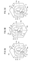
- FIG. 5A to FIG. 5C are schematic explanatory diagrams showing the positional relationship between the image area represented by each cross-sectional image group and the human body image.
- 6A to 6C are schematic diagrams for explaining a positioning method in each cross-sectional image group.
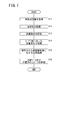
- FIG. 3 is a second flowchart for explaining the operation of the image processing apparatus shown in FIGS. 1 and 2.
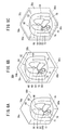
- FIG. It is the elements on larger scale of the cross-sectional image group shown in FIG. It is the elements on larger scale of the new cross-sectional image group after performing the alignment process with respect to the cross-sectional image group of FIG.
- FIG. 1 is a schematic configuration diagram of a medical diagnosis system 10 in which an image processing apparatus 26 common to the first and second embodiments is incorporated.
- the medical diagnosis system 10 basically includes a modality 14 that generates a medical image related to a subject 12, an image server 16 that stores and manages medical images, and an image diagnostic apparatus 18 that displays medical images for diagnosis and the like. I have.
- the modality 14, the image server 16, and the image diagnostic apparatus 18 are connected via the network 20.
- the modality 14 shoots the subject 12 to generate a medical image used for diagnosis.
- the modality 14 outputs the generated medical image and its accompanying information (such as imaging conditions and information on the subject 12) to the image server 16 side.
- the modality 14 includes a CR (Computed Radiography) device 22 and an X-ray CT (Computed Tomography) device 24.
- the configuration of the apparatus is not limited to this.
- an image generating apparatus such as a DR (Digital Radiography) apparatus, an MRI (Magnetic Resonance Imaging) apparatus, an ultrasound (US) diagnostic apparatus, a PET (Positron Emission Tomography) apparatus, or the like may be appropriately combined. Good.
- the image server 16 stores and manages an image processing device 26 that is a computer that can execute desired image processing on the medical image supplied from the modality 14 and a medical image that has been subjected to image processing by the image processing device 26.
- Storage device 28 stores and manages an image processing device 26 that is a computer that can execute desired image processing on the medical image supplied from the modality 14 and a medical image that has been subjected to image processing by the image processing device 26.
- FIG. 2 is an electrical schematic block diagram of the image processing apparatus 26 shown in FIG.
- the image processing device 26 includes a communication I / F 30, a memory 32 (storage medium), and a control unit 34.
- the communication I / F 30 is an interface that transmits and receives electrical signals from an external device.
- the image processing device 26 acquires medical images stored and managed by the storage device 28 (see FIG. 1) via the communication I / F 30.
- This medical image may be either a two-dimensional image or a three-dimensional image, and specifically may be a radiographic image (so-called radiation simple image), a CT image, an MRI image, a PET image, or the like.
- the memory 32 stores a program and data necessary for the control unit 34 to control each component.
- the memory 32 may be a non-transitory non-transitory storage medium such as a non-volatile memory or a hard disk.
- a temporal cross-sectional image group 36, a temporal cross-sectional image 38, alignment data 40, and compressed data 42 each including three cross-sectional image groups 36a to 36c are illustrated.
- a plurality of original images (time-lapse cross-sectional image group 36 and time-lapse cross-sectional image 38) obtained by photographing the same subject 12 in time series are collectively referred to as a time-series image 44.
- the control unit 34 is configured by an information calculation device such as a CPU (Central Processing Unit).
- the control unit 34 reads out and executes the program stored in the memory 32, thereby recognizing the time-series image acquisition unit 46 that acquires the time-series image 44 and the part (tissue) of the subject 12 included in the time-series image 44.
- At least one original image among the common part designating unit 50 and the time series image 44 for designating at least one part (hereinafter, referred to as a common part) that is commonly included in the part recognition unit 48 and the time series image 44 is represented.
- An alignment processing unit 52 that aligns the position of the common part with the position of the common part represented by another original image, and a time-series image (new time-series image) aligned by the alignment processing unit 52 Respectively function as an image compression processing unit 54 that performs moving image compression processing.
- the image processing apparatus 26 common to the first and second embodiments is configured as described above. Next, the operation of the image processing apparatus 26 will be described in detail with reference mainly to the flowcharts of FIGS.
- the image processing apparatus 26 acquires a time-lapse cross-sectional image group 36 that is a time series of cross-sectional image groups via the communication I / F 30. Specifically, the image processing device 26 acquires a temporal cross-sectional image group 36 which is a medical image stored in the storage device 28 and obtained by photographing the same subject 12.
- FIG. 4 is a schematic diagram showing an example of a cross-sectional image group 36a on the chest of the subject 12.
- the cross-sectional images are arranged at equal intervals along the Z axis (predetermined axis).
- the image processing apparatus 26 uses the time-lapse cross-sectional image group 36 as a cross-sectional image group 36a in the first photographing, a cross-sectional image group 36b in the second photographing, and a cross-sectional image group 36c in the third photographing (see FIG. 2). Is acquired and then temporarily stored in the memory 32.
- the time-lapse cross-sectional image group 36 is not limited to three cross-sectional image groups, and the number of groups is not limited.
- FIGS. 5A to 5C are schematic explanatory diagrams showing the positional relationship between the image areas 58a to 58c represented by the cross-sectional image groups 36a to 36c and the human body image 60.
- FIG. 5A to 5C are schematic explanatory diagrams showing the positional relationship between the image areas 58a to 58c represented by the cross-sectional image groups 36a to 36c and the human body image 60.
- the cross-sectional image group 36a constitutes a three-dimensional image region 58a.
- a human body image 60 of the subject 12 photographed from the back side is formed.
- the human body image 60 has a body part region (hereinafter, simply “body part 62”).
- body part 62 a right lung 64, a left lung 66, a heart 68, a liver 70, a stomach 72, a spleen 74, and a kidney 76 are arranged.
- the cross-sectional image group 36b constitutes a three-dimensional image region 58b.
- a human body image 60 (the body part 62 and its internal configuration are also the same) is formed as in FIG. 5A.
- the cross-sectional image group 36c constitutes a three-dimensional image region 58c.
- a human body image 60 (the body part 62 and its internal configuration are also the same) is formed as in FIG. 5A.
- a cross-sectional image group 36a (b, c) is obtained in which a plurality of cross-sectional images are arranged in time series over 80a (b, c).
- the shooting start position (position of the upper surface 78b) in the second shooting is different from the shooting start positions (positions of the upper surfaces 78a and 78c) in the first and third shooting
- the human body image 60 in the image region 58a is The image areas 58a and 58c are relatively above the image areas 58a and 58c. Since the image processing conditions in the third shooting are different from the image processing conditions in the first and second shooting, the human body image 60 in the image area 58c is relatively left compared to the image areas 58a and 58b. Exists.
- the part recognition unit 48 recognizes each part of the body part 62 represented in each of the cross-sectional image groups 36a to 36c acquired in step S1.
- Various known algorithms can be applied as the part recognition technique.
- the part recognizing unit 48 provisionally determines the part of the body part 62 represented in each of the cross-sectional image groups 36a to 36c among the plurality of reference parts based on a predetermined evaluation index, and the cross-sectional image group 36a A cost map in which a cost is set according to the combination of ⁇ 36c and the reference part may be created, and the part may be corrected so that the cost of the cost map is minimized (refer to Japanese Patent No. 4855141 for details) ).
- the common part designating unit 50 designates common parts included in the cross-sectional image groups 36a to 36c in common.
- the common part designating unit 50 designates a part that specifies a position along the Z-axis direction (see FIG. 4) as a common part.
- This designation is an automatic designation instruction based on the result of the image recognition process executed in step S2, but is a designation instruction through an input means (not shown) by a doctor or an engineer (hereinafter referred to as a user). May be.
- the slice number of the cross-sectional image group 36a and the like may be detected from the Z coordinate of the designated common part.
- the common part may be, for example, the upper end or lower end of a relatively large organ (including lung, liver, etc.), or a relatively small organ (specific bone, navel, etc.). Including itself).
- the common part is a part uniquely identified from the form of the organ, for example, a specific branch of the bronchus, the upper edge of the aortic arch, the start or branch of the left and right coronary arteries, the branch of the pulmonary artery and pulmonary vein, It may be a specific branch of a hepatic artery, portal vein, or vein.
- the common part designating unit 50 designates the lower end part (position marked with a black circle) of the left lung 66 included in common in the image regions 58a to 58c as the common part 82.
- the time-lapse cross-sectional image group 36 one cross-sectional image group 36a is set as a reference image (group) for alignment, and the remaining cross-sectional image group 36a is set as a target image (group) for alignment.
- Reference numeral 84 indicates the relative position of the common part 82 in the image region 58a, and is hereinafter referred to as a target position 84.
- step S4 the alignment processing unit 52 aligns the common portion 82 along the Z axis (axial direction) with respect to the time-lapse cross-sectional image group 36. Specifically, the alignment processing unit 52 relatively moves the image region 58b or the human body image 60 based on the relationship between the position (that is, the relative position) of the common portion 82 in the image region 58b and the target position 84.
- the alignment processing unit 52 adjusts the position of the common part 82 to the target position 84 by translating the image region 58b (or the human body image 60) upward (or downward) by a predetermined amount.
- an adjusted image 90b a new group of cross-sectional images in which a plurality of cross-sectional images are arranged in time series from the upper surface 86b to the lower surface 88b is obtained.
- step S5 the alignment processing unit 52 aligns the common portion 82 along the XY plane (cross-sectional direction) with the Z-axis direction (axial direction) as a normal line with respect to the time-lapse cross-sectional image group 36. Do. Specifically, the alignment processing unit 52 relatively moves the image region 58c or the human body image 60 from the relationship between the position (that is, the relative position) of the common part 82 in the image region 58c and the target position 84.
- the alignment processing unit 52 adjusts the position of the common part 82 to the target position 84 by translating the image region 58c (or human body image 60) to the left (or right) by a predetermined amount.
- an adjusted image 90c a new group of cross-sectional images in which a plurality of cross-sectional images are arranged in time series from the upper surface 86c to the lower surface 88c is obtained.
- the alignment processing unit 52 may appropriately perform registration processing on the voxel data.
- step S6 the image compression processing unit 54 applies moving images to the time-series images adjusted in steps S4 and S5 (specifically, the cross-sectional image group 36a as the position reference and the adjusted images 90b and 90c).
- Perform image compression processing For this processing, various known digital moving image compression methods including MPEG-2, 4 (Motion Picture Expanding Group) may be applied, and either reversible compression or lossy compression may be used.
- MPEG-2 Motion Picture Expanding Group
- 4 Motion Picture Expanding Group
- a method related to inter-frame prediction, motion compensation, transform coding, and the like may be selected as appropriate.
- the cross-sectional image group 36a and the human body images 60 of the adjusted images 90b and 90c are all formed at substantially the same position in three dimensions.
- the amount of image change between these images is zero or very small. That is, when the cross-sectional image group 36a and the adjusted images 90b and 90c are arranged in time series for each slice and then subjected to compression processing, compressed data 42 with an extremely high compression rate can be obtained. In particular, it is more effective when the structure of the photographed subject 12 is known or its change with time is relatively small.
- step S7 the image processing device 26 stores the compressed data 42 obtained in step S6 in the memory 32 or the external device (storage device 28). At that time, together with the compressed data 42, the alignment data 40 created in step S5 is also linked and stored. Thereby, the diagnostic imaging apparatus 18 can restore the temporal cross-sectional image group 36 by executing the predetermined development process and the alignment process (inverse transformation) after receiving the compressed data 42 and the alignment data 40.
- the time-series image acquisition unit 46 acquires the cross-sectional image group 36a (see FIGS. 4 and 8) as the time-series image 44.
- the part recognizing unit 48 recognizes each part of the body part represented in the cross-sectional image group 36a acquired in step S11. Steps S11 and S12 are the same as those in the first embodiment, and a description thereof will be omitted.
- the common part designating unit 50 designates at least one common part included in common in the original images Io (1) to Io (15) of the cross-sectional image group 36a.
- part (structure) which performs the alignment process over a some cross-sectional image is designated.
- the common part designating unit 50 may designate at least one of the lung, liver, heart, spleen, kidney, head, and body as the common part.
- step S14 the alignment processing unit 52 aligns the common part along the XY plane (cross-sectional direction) with respect to the cross-sectional image group 36a. Specifically, the alignment processing unit 52 uses the rigid or non-rigid registration method to match the cross-sectional shape of the common part.
- a body part region (hereinafter simply referred to as a body part 100) of the subject 12 (see FIG. 1) is formed on the original image Io (1) of the cross-sectional image group 36a.
- a right lung region (hereinafter simply referred to as the right lung 102), a left lung region (hereinafter simply referred to as the left lung 104), and an esophageal bone region (hereinafter simply referred to as the esophagus 106) are formed in the body portion 100 having a substantially elliptical shape.
- the body portion 100 having a substantially elliptical shape.
- a right lung 108 having a shape different from that of the right lung 102 is formed.
- the right lung 108 bulges outward (leftward in the drawing) with respect to the right lung 102.
- the difference area excluding the right lung 102 from the right lung 108 is referred to as a bulging portion 110.
- a left lung 112 having a shape different from that of the left lung 104 is formed in the body part 100.
- the left lung 112 bulges outward (to the right in the drawing) with respect to the left lung 104.
- the difference area obtained by excluding the left lung 104 from the left lung 112 is referred to as a bulging portion 114.
- the alignment processing unit 52 aligns the position of the common part represented by the original image Io (2) with the position of the common part represented by the adjacent original image Io (1) in time series.
- the alignment processing unit 52 transforms the right lung 108 on the original image Io (2) into the right lung 108r by using a non-rigid registration method, for example, and the left lung on the original image Io (2). 112 is transformed into the left lung 112r.
- the body part 100 is an object of the alignment process, like the lung.
- the body part 100 has the same shape on the original images Io (1) and Io (2) and is disposed at the same position. For this reason, the form of the body part 100 does not change before and after this process.
- the alignment processing unit 52 determines the position of the common part represented by the original image Io (n + 1) (n is an integer of 2 or more) as the common part represented by the original image Io (n) adjacent in time series. Adjust to each position. As a result, a new cross-sectional image group 120a in which a plurality of cross-sectional images ⁇ Io (1), Ir (2; 1) to Ir (N; N-1) ⁇ are arranged in time series is obtained.
- the adjusted image Ir (2; 1) shows a cross-sectional image after the position of the common part represented by the original image Io (2) is matched with the position of the common part represented by the original image Io (1).
- each part of the original image Io (1) and the adjusted image Ir (2; 1) is formed at substantially the same position two-dimensionally.
- the amount of image change between these images is zero or very small. That is, if the original image Io (1), the adjusted image Ir (2; 1), etc. are arranged in time series for each slice and then subjected to compression processing, compressed data 42 with an extremely high compression rate can be obtained.
- the image processing device 26 has acquired the time-series image acquisition unit 46 that acquires the time-series images 44 (time-lapse cross-sectional image group 36 and time-lapse cross-sectional image 38) generated by time-series imaging.
- a common part designating unit 50 for designating at least one common part 82 (102, 104) included in common in the time series image 44, and a common part 82 (108 represented by at least one original image in the time series image 44).
- the position of the common part 82 (108, 112) represented by at least one original image in the time series image 44 is adjusted to the position of the common part 82 (102, 104) represented by another original image, respectively. Therefore, a time-series image with a small image change amount between the frames can be obtained at least in the common part 82 (102, 104). By compressing the adjusted new time series image, the compression efficiency of the time series image can be further improved.
- the present invention is not limited to the above-described embodiment, and it is needless to say that the present invention can be freely changed without departing from the gist of the present invention.
- the processing forms of the first and second embodiments may be appropriately combined.
- a specific example in which a compression process is performed on a medical image has been described.
- the present invention can also be applied to uses other than medical use.
Landscapes
- Health & Medical Sciences (AREA)
- Life Sciences & Earth Sciences (AREA)
- Engineering & Computer Science (AREA)
- Medical Informatics (AREA)
- Physics & Mathematics (AREA)
- General Health & Medical Sciences (AREA)
- Veterinary Medicine (AREA)
- Biophysics (AREA)
- Biomedical Technology (AREA)
- Heart & Thoracic Surgery (AREA)
- Pathology (AREA)
- Molecular Biology (AREA)
- Surgery (AREA)
- Animal Behavior & Ethology (AREA)
- Public Health (AREA)
- Nuclear Medicine, Radiotherapy & Molecular Imaging (AREA)
- Radiology & Medical Imaging (AREA)
- Physiology (AREA)
- Computer Vision & Pattern Recognition (AREA)
- Psychiatry (AREA)
- Signal Processing (AREA)
- Artificial Intelligence (AREA)
- High Energy & Nuclear Physics (AREA)
- Pulmonology (AREA)
- Optics & Photonics (AREA)
- Theoretical Computer Science (AREA)
- General Physics & Mathematics (AREA)
- Apparatus For Radiation Diagnosis (AREA)
- Magnetic Resonance Imaging Apparatus (AREA)
Abstract
本発明は、画像処理装置、方法及び記録媒体に関する。時系列画像(36、38)に共通して含まれる共通部位(82、102、104)を少なくとも1つ指定する。そして、時系列画像(36、38)のうち少なくとも1枚の原画像が表す共通部位(82、108、112)の位置を、別の1枚の原画像が表す共通部位(82、102、104)の位置にそれぞれ合わせることで、時系列画像(36、38)を調整する。そして、調整された新たな時系列画像(90b、90c、120a)に対して動画像圧縮処理を行う。
Description
本発明は、画像処理装置、方法及び記憶媒体に関する。
近時、医療分野において、画像撮影装置(あるいはモダリティ)の高性能化・低線量化技術の飛躍的な発展に伴って、1回の検査につき取得可能な医用画像の数が増加しつつある。その反面、医療診断システム全体として取り扱うデータ量が膨大になるので、データの保管・通信等のためのコストが高騰する等の問題が顕在化している。そこで、医用画像を送信又は保存する前に画像圧縮処理を施し、取り扱うデータ量を低減させることが効果的である(特開2003-126046号公報参照)。また、画像の圧縮効率を向上させるための技術が種々提案されている。
特開2009-291280号公報では、画素の変化方向に沿って断面画像の順番をソートした後に、動画とみなして画像圧縮処理を施すシステム及び方法が提案されている。
特開2005-245922号公報では、位置が互いに共通している画素に関する画像データをブロック単位として符号化した後、グループ化して画像を圧縮する方法及び装置が提案されている。
ところで、特開2009-291280号公報及び特開2005-245922号公報に記載された方法等は、隣接するフレーム間における画像の変化量に着目し、その変化量が少なくなるように断面画像をソート(又はグループ化)することで、圧縮効率の向上を図っている。しかしながら、撮影された被写体の構造が既知である場合、あるいは、その構造の経時変化が比較的小さい場合において、当該構造を表す時系列画像の圧縮効率をさらに向上する余地が十分にある。
本発明は上記した問題を解決するためになされたもので、時系列画像の圧縮効率をさらに向上可能な画像処理装置、方法及び記録媒体を提供することを目的とする。
本発明に係る画像処理装置は、時系列的な撮影により生成された複数の原画像からなる時系列画像を取得する時系列画像取得部と、前記時系列画像取得部により取得された前記時系列画像に共通して含まれる共通部位を少なくとも1つ指定する共通部位指定部と、前記時系列画像のうち少なくとも1枚の原画像が表す前記共通部位の位置を、別の1枚の原画像が表す前記共通部位の位置にそれぞれ合わせることで、前記時系列画像を調整する位置合わせ処理部と、前記位置合わせ処理部により調整された新たな時系列画像に対して動画像圧縮処理を行う画像圧縮処理部とを有することを特徴とする。
このように、時系列画像のうち少なくとも1枚の原画像が表す共通部位の位置を、別の1枚の原画像が表す前記共通部位の位置にそれぞれ合わせる位置合わせ処理部を設けたので、少なくとも共通部位において、各フレーム間での画像変化量が小さい時系列画像を得ることができる。この調整された新たな時系列画像を圧縮することで、時系列画像の圧縮効率をさらに向上することができる。
また、前記時系列画像取得部は、前記時系列画像として、軸方向に沿ったスライス撮影により生成された断面画像群の時系列を取得し、前記位置合わせ処理部は、前記軸方向に沿って前記共通部位の位置を合わせることで前記時系列画像を調整することが好ましい。
さらに、前記位置合わせ処理部は、前記時系列画像のうち1枚の原画像が表す前記共通部位の位置を基準とし、残余の原画像が表す前記共通部位の位置をそれぞれ合わせることで、前記時系列画像を調整することが好ましい。
さらに、前記位置合わせ処理部は、前記軸方向を法線とする断面方向に沿って前記共通部位の位置を合わせることで前記時系列画像を調整することが好ましい。
また、前記時系列画像取得部は、前記時系列画像として、軸方向に沿ったスライス撮影により生成された断面画像群を取得し、前記位置合わせ処理部は、前記軸方向を法線とする断面方向に沿って前記共通部位の位置を合わせることで前記時系列画像を調整することが好ましい。
さらに、前記位置合わせ処理部は、各前記原画像が表す前記共通部位の位置を、時系列的に隣接する原画像が表す前記共通部位の位置にそれぞれ合わせることで、前記時系列画像を調整することが好ましい。
さらに、前記共通部位指定部は、肺、肝臓、心臓、脾臓、腎臓、頭部及び体部のうちの少なくとも1つを前記共通部位として指定することが好ましい。
本発明に係る画像処理方法は、時系列的に撮影された複数の原画像からなる時系列画像を取得する取得ステップと、取得された前記時系列画像に共通して含まれる共通部位を少なくとも1つ指定する指定ステップと、前記時系列画像のうち少なくとも1枚の原画像が表す前記共通部位の位置を、別の1枚の原画像が表す前記共通部位の位置にそれぞれ合わせることで、前記時系列画像を調整する位置合わせステップと、調整された新たな時系列画像に対して動画像圧縮処理を行う圧縮ステップとを備えることを特徴とする。
また、前記位置合わせステップでは、前記共通部位の位置を合わせるための位置合わせデータをさらに取得し、前記圧縮ステップで得られた圧縮データを前記位置合わせデータに紐付けて格納する格納ステップをさらに備えることが好ましい。
本発明に係るプログラムは、プログラムを格納したコンピュータ読取可能な記録媒体であって、前記プログラムは、コンピュータに、時系列的に撮影された複数の原画像からなる時系列画像を取得するステップ、取得された前記時系列画像に共通して含まれる共通部位を少なくとも1つ指定するステップ、前記時系列画像のうち少なくとも1枚の原画像が表す前記共通部位の位置を、別の1枚の原画像が表す前記共通部位の位置にそれぞれ合わせることで、前記時系列画像を調整するステップ、調整された新たな時系列画像に対して動画像圧縮処理を行うステップをそれぞれ実行させることを特徴とする。
本発明に係る画像処理装置、方法及び記録媒体によれば、時系列画像のうち少なくとも1枚の原画像が表す共通部位の位置を、別の1枚の原画像が表す前記共通部位の位置にそれぞれ合わせるようにしたので、少なくとも共通部位において、各フレーム間での画像変化量が小さい時系列画像を得ることができる。この調整された新たな時系列画像を圧縮することで、時系列画像の圧縮効率をさらに向上することができる。
以下、本発明に係る画像処理方法について、これを実施する画像処理装置及び記録媒体(プログラム)との関係において好適な実施形態を挙げ、添付の図面を参照して説明する。
[各実施形態に共通するシステム構成]
図1は、第1及び第2実施形態に共通する画像処理装置26が組み込まれた医療診断システム10の概略構成図である。
図1は、第1及び第2実施形態に共通する画像処理装置26が組み込まれた医療診断システム10の概略構成図である。
医療診断システム10は、被写体12に関する医用画像を生成するモダリティ14と、医用画像を保存・管理する画像サーバ16と、診断等のために医用画像を表示する画像診断装置18と、を基本的に備えている。モダリティ14、画像サーバ16及び画像診断装置18は、ネットワーク20を介してそれぞれ接続されている。
モダリティ14は、被写体12を撮影することで、診断に供される医用画像を生成する。モダリティ14は、生成した医用画像及びその付帯情報(撮影条件や被写体12の情報等)を画像サーバ16側に出力する。本図例では、モダリティ14は、CR(Computed Radiography)装置22と、X線CT(Computed Tomography)装置24とから構成されている。装置構成はこれに限られず、例えば、DR(Digital Radiography)装置、MRI(Magnetic Resonance Imaging)装置、超音波(US)診断装置、PET(Positron Emission Tomography)装置等の画像生成装置を適宜組み合わせてもよい。
画像サーバ16は、モダリティ14から供給された医用画像に対して所望の画像処理を実行可能なコンピュータである画像処理装置26と、画像処理装置26により画像処理が施された医用画像を保存・管理するストレージ装置28とを備える。
図2は、図1に示す画像処理装置26の電気的な概略ブロック図である。画像処理装置26は、通信I/F30、メモリ32(記憶媒体)、及び制御部34を備えている。
通信I/F30は、外部装置からの電気信号を送受信するインターフェースである。例えば、画像処理装置26は、通信I/F30を介して、ストレージ装置28(図1参照)で保存・管理された医用画像を取得する。この医用画像は、二次元画像又は三次元画像のいずれでもよく、具体的には、放射線画像(いわゆる放射線単純画像)、CT画像、MRI画像、PET画像等であってもよい。
メモリ32には、制御部34が各構成要素を制御するのに必要なプログラム及びデータ等を記憶している。メモリ32は、不揮発性のメモリ、ハードディスク等の非一過性であり、コンピュータ読取可能な記憶媒体であってよい。本図例では、3つの断面画像群36a~36cから構成される経時断面画像群36、経時断面画像38、位置合わせデータ40及び圧縮データ42がそれぞれ図示されている。以下、同一の被写体12を時系列的に撮影して得た複数の原画像(経時断面画像群36、経時断面画像38)を総称して時系列画像44という。
制御部34は、CPU(Central Processing Unit)等の情報演算装置によって構成されている。制御部34は、メモリ32に格納されたプログラムを読み出し実行することで、時系列画像44を取得する時系列画像取得部46、時系列画像44に含まれる被写体12の部位(組織)を認識する部位認識部48、時系列画像44に共通して含まれる部位(以下、共通部位という。)を少なくとも1つ指定する共通部位指定部50、時系列画像44のうち少なくとも1枚の原画像が表す共通部位の位置を、別の1枚の原画像が表す共通部位の位置にそれぞれ合わせる位置合わせ処理部52、及び、位置合わせ処理部52によって位置合わせされた時系列画像(新たな時系列画像)に対して動画像圧縮処理を行う画像圧縮処理部54としてそれぞれ機能する。
第1及び第2実施形態に共通する画像処理装置26は、以上のように構成される。続いて、画像処理装置26の動作について、図3及び図7のフローチャートを主に参照しながら詳細に説明する。
[第1実施形態]
先ずは、異なる時点で撮影・生成された断面画像群の時系列に対して画像圧縮処理を行う第1実施形態について、図3~図6Cを参照しながら説明する。
先ずは、異なる時点で撮影・生成された断面画像群の時系列に対して画像圧縮処理を行う第1実施形態について、図3~図6Cを参照しながら説明する。
図3のステップS1において、画像処理装置26は、通信I/F30を介して、断面画像群の時系列である経時断面画像群36を取得する。具体的には、画像処理装置26は、ストレージ装置28に保存された医用画像であって、同一の被写体12を撮影して得た経時断面画像群36を取得する。
図4は、被写体12の胸部における断面画像群36aの一例を表す模式図である。断面画像群36aは、X-Y平面(X軸及びY軸のそれぞれ)に平行する複数の断面画像である原画像Io(1)~Io(N)(本図例では、N=15)から構成される。そして、各断面画像は、Z軸(所定軸)に沿って等間隔に配置されている。第1実施形態において、画像処理装置26は、経時断面画像群36として、第1撮影における断面画像群36a、第2撮影における断面画像群36b、第3撮影における断面画像群36c(図2参照)を取得した後、メモリ32に一時的に格納させたとする。なお、経時断面画像群36は、3つの断面画像群に限られることなく、グループの数は問わない。
図5A~図5Cは、各断面画像群36a~36cが表す画像領域58a~58cと、人体像60との間の位置関係を示す概略説明図である。
図5Aに示すように、断面画像群36aは、三次元の画像領域58aを構成する。この画像領域58a内には、背側から撮影された被写体12(図1参照)の人体像60が形成されている。人体像60は、体部領域(以下、単に「体部62」)を有している。体部62内には、右肺64、左肺66、心臓68、肝臓70、胃72、脾臓74、及び腎臓76がそれぞれ配置されている。
図5Bに示すように、断面画像群36bは、三次元の画像領域58bを構成する。この画像領域58b内には、図5Aと同様に、人体像60(体部62及びその内部構成も同様である。)が形成されている。
図5Cに示すように、断面画像群36cは、三次元の画像領域58cを構成する。この画像領域58c内には、図5Aと同様に、人体像60(体部62及びその内部構成も同様である。)が形成されている。
ここでは、X線CT装置24(図1参照)を用いて、被写体12の体軸方向に沿ったスライス撮影(第1~第3撮影)を行うことで、上面78a(b、c)から下面80a(b、c)にわたって複数の断面画像を時系列的に配列した断面画像群36a(b、c)が得られる。例えば、第2撮影における撮影開始位置(上面78bの位置)が、第1及び第3撮影における撮影開始位置(上面78a、78cの位置)と異なっていたので、画像領域58a内の人体像60は、画像領域58a、58cと比べて相対的に上方に存在している。また、第3撮影における画像処理条件が、第1及び第2撮影における画像処理条件と異なっていたので、画像領域58c内の人体像60は、画像領域58a、58bと比べて相対的に左方に存在している。
ステップS2において、部位認識部48は、ステップS1で取得された各断面画像群36a~36cに表された体部62の部位をそれぞれ認識する。部位の認識手法として、公知のアルゴリズムを種々適用できる。例えば、部位認識部48は、所定の評価指標に基づいて、複数の参照部位のうちの各断面画像群36a~36cに表された体部62の部位を暫定的に決定し、断面画像群36a~36c及び参照部位の組み合わせに応じてコストが設定されたコストマップを作成し、該コストマップのコストが最小になるように部位を修正してもよい(詳細は、特許第4855141号公報を参照)。
ステップS3において、共通部位指定部50は、断面画像群36a~36cに共通して含まれる共通部位を指定する。第1実施形態では、共通部位指定部50は、Z軸方向(図4参照)に沿った位置を特定する部位を、共通部位として指定する。この指定は、ステップS2で実行された画像認識処理の結果に基づいた自動的な指定指示であっても、医師又は技師(以下、ユーザという。)による図示しない入力手段を介した指定指示であってもよい。また、指定された共通部位のZ座標から、断面画像群36a等のスライス番号を検出してもよい。
共通部位は、例えば、サイズが相対的に大きい臓器(肺、肝臓等を含む。)の上端部又は下端部であってもよいし、サイズが相対的に小さい臓器(特定の骨、臍等を含む。)自体であってもよい。また、共通部位は、臓器の形態から一意に特定される部位、例えば、気管支の特定の分岐部、大動脈弓の上縁部、左右冠動脈の始点部又は分岐部、肺動脈・肺静脈の分岐部、肝臓動脈・門脈・静脈の特定の分岐部であってもよい。
ここでは、図6Aに示すように、共通部位指定部50は、画像領域58a~58cに共通して含まれる左肺66の下端部(黒丸印を付した位置)を共通部位82として指定したとする。また、経時断面画像群36のうち、1つの断面画像群36aを位置合わせの基準画像(群)とし、残余の断面画像群36aを位置合わせの対象画像(群)とする。参照符号84は、画像領域58a内での共通部位82の相対位置を示しており、以下、目標位置84と称する。
ステップS4において、位置合わせ処理部52は、経時断面画像群36に対してZ軸(軸方向)に沿った共通部位82の位置合わせを行う。具体的には、位置合わせ処理部52は、画像領域58bでの共通部位82の位置(すなわち相対位置)と目標位置84との関係から、画像領域58b又は人体像60を相対移動させる。
図6Bに示すように、共通部位82の相対位置(黒丸印を付した位置)は、目標位置84(白抜き丸印を付した位置)よりも僅か上方に存在する。この場合、位置合わせ処理部52は、画像領域58b(又は人体像60)を上方(又は下方)に所定量だけ平行移動させることで、共通部位82の位置を目標位置84に合わせる。これにより、上面86bから下面88bにわたって複数の断面画像を時系列的に配列した新たな断面画像群(以下、調整済み画像90bという。)が得られる。
ステップS5において、位置合わせ処理部52は、経時断面画像群36に対して、Z軸方向(軸方向)を法線とするX-Y平面(断面方向)に沿って共通部位82の位置合わせを行う。具体的には、位置合わせ処理部52は、画像領域58cでの共通部位82の位置(すなわち相対位置)と目標位置84との関係から、画像領域58c又は人体像60を相対移動させる。
図6Cに示すように、共通部位82の相対位置(黒丸印を付した位置)は、目標位置84(白抜き丸印を付した位置)よりも僅か左方に存在する。この場合、位置合わせ処理部52は、画像領域58c(又は人体像60)を左方(又は右方)に所定量だけ平行移動させることで、共通部位82の位置を目標位置84に合わせる。これにより、上面86cから下面88cにわたって複数の断面画像を時系列的に配列した新たな断面画像群(以下、調整済み画像90cという。)が得られる。
ところで、同一の被写体12内の同一部位を撮影したにもかかわらず、撮影時点によって当該部位の形状及び位置が異なることがある。これは、被写体12の体型の変化、撮影時の体動を含む各種環境が変化するためである。この場合、位置合わせ処理部52は、ボクセルデータに対してレジストレーション処理を適宜施してもよい。
ステップS6において、画像圧縮処理部54は、ステップS4、S5でそれぞれ調整された時系列画像(具体的には、位置基準としての断面画像群36a、及び調整済み画像90b、90c)に対して動画像圧縮処理を行う。この処理には、MPEG-2、4(Motion Picture Expanding Group)を含む公知のデジタル動画像圧縮手法を種々適用してもよく、可逆圧縮、非可逆圧縮のいずれであってもよい。また、圧縮効率及び演算時間の観点から、フレーム間予測、動き補償、変換符号化等に関する手法を適宜選択してもよい。
図6A~図6Cに示すように、断面画像群36a、調整済み画像90b、90cの人体像60は、いずれも三次元的に略同じ位置に形成されている。これらの画像間での画像変化量はゼロであるか微小である。すなわち、断面画像群36a、調整済み画像90b、90cをスライス毎に時系列で配列した上で圧縮処理を施すと、極めて高い圧縮率の圧縮データ42を得ることができる。特に、撮影された被写体12の構造が既知であり、あるいは、その経時変化が比較的小さい場合、一層効果的である。
ステップS7において、画像処理装置26は、ステップS6で得られた圧縮データ42を、メモリ32又は外部装置(ストレージ装置28)に格納させる。その際、圧縮データ42とともに、ステップS5で作成された位置合わせデータ40も紐付けて格納する。これにより、画像診断装置18は、圧縮データ42及び位置合わせデータ40を受信した後、所定の展開処理及び位置合わせ処理(逆変換)を実行することで、経時断面画像群36を復元できる。
[第2実施形態]
続いて、スライス撮影により生成された断面画像群を保存・管理する第2実施形態について、図7~図9を参照しながら説明する。
続いて、スライス撮影により生成された断面画像群を保存・管理する第2実施形態について、図7~図9を参照しながら説明する。
図7のステップS11において、時系列画像取得部46は、時系列画像44としての断面画像群36a(図4及び図8参照)を取得する。ステップS12において、部位認識部48は、ステップS11で取得された断面画像群36aに表された体部の部位をそれぞれ認識する。なお、ステップS11及びS12は、第1実施形態と同様であるため、その説明を省略する。
ステップS13において、共通部位指定部50は、断面画像群36aの原画像Io(1)~Io(15)に共通して含まれる共通部位を少なくとも1つ指定する。第2実施形態では、複数の断面画像を跨いた位置合わせ処理を行う部位(構造物)を指定する。共通部位指定部50は、共通部位として、例えば、肺、肝臓、心臓、脾臓、腎臓、頭部及び体部のうちの少なくとも1つを指定してもよい。第2実施形態では、例えば、肺及び体部が指定されたとする。
ステップS14において、位置合わせ処理部52は、断面画像群36aに対してX-Y平面(断面方向)に沿って共通部位の位置合わせを行う。具体的には、位置合わせ処理部52は、剛性型又は非剛性型のレジストレーション手法を用いて、共通部位の断面形状を合わせる。
図8に示すように、断面画像群36aの原画像Io(1)上には、被写体12(図1参照)の体部領域(以下、単に体部100という。)が形成されている。概略楕円形状の体部100内に、右肺領域(以下、単に右肺102)、左肺領域(以下、単に左肺104)、及び食道骨領域(以下、単に食道106)がそれぞれ形成されている。なお、説明の便宜のため、図8及び図9では、画像の背景部及び各部位の輪郭のみを表記する。
原画像Io(2)上の体部100には、右肺102と異なる形状を有する右肺108が形成されている。右肺108は、右肺102に対して外方(図面の左方)に膨出している。ここで、右肺108から右肺102を除外した差分領域のことを膨出部110という。また、体部100には、左肺104と異なる形状を有する左肺112が形成されている。左肺112は、左肺104に対して外方(図面の右方)に膨出している。ここで、左肺112から左肺104を除外した差分領域のことを膨出部114という。
位置合わせ処理部52は、原画像Io(2)が表す共通部位の位置を、時系列的に隣接する原画像Io(1)が表す共通部位の位置にそれぞれ合わせる。位置合わせ処理部52は、例えば非剛性型のレジストレーション手法を用いることで、原画像Io(2)上の右肺108を右肺108rに変形させるとともに、原画像Io(2)上の左肺112を左肺112rに変形させる。
ところで、体部100は、肺と同様に、位置合わせ処理の対象である。しかし、体部100は、原画像Io(1)、Io(2)上において同じ形状を有し、且つ、同じ位置に配置されている。このため、体部100の形態は、本処理の前後にわたって変化しない。
そして同様に、位置合わせ処理部52は、原画像Io(n+1)(nは2以上の整数)が表す共通部位の位置を、時系列的に隣接する原画像Io(n)が表す共通部位の位置にそれぞれ合わせる。これにより、複数の断面画像{Io(1)、Ir(2;1)~Ir(N;N-1)}を時系列的に配列した新たな断面画像群120aが得られる。調整済み画像Ir(2;1)は、原画像Io(2)が表す共通部位の位置を、原画像Io(1)が表す共通部位の位置にそれぞれ合わせた後の断面画像を示す。
図9に示すように、原画像Io(1)及び調整済み画像Ir(2;1)の各部位は、いずれも二次元的に略同じ位置に形成されている。これらの画像間での画像変化量はゼロであるか微小である。すなわち、原画像Io(1)、調整済み画像Ir(2;1)等をスライス毎に時系列で配列した上で圧縮処理を施すと、極めて高い圧縮率の圧縮データ42を得ることができる。
以上のように、画像処理装置26は、時系列的な撮影により生成された時系列画像44(経時断面画像群36、経時断面画像38)を取得する時系列画像取得部46と、取得された時系列画像44に共通して含まれる共通部位82(102、104)を少なくとも1つ指定する共通部位指定部50と、時系列画像44のうち少なくとも1枚の原画像が表す共通部位82(108、112)の位置を、別の1枚の原画像が表す共通部位82(102、104)の位置にそれぞれ合わせることで、時系列画像44を調整する位置合わせ処理部52と、調整された新たな時系列画像(調整済み画像90b、90c、新たな断面画像群120a)に対して動画像圧縮処理を行う画像圧縮処理部54と、を有する。
時系列画像44のうち少なくとも1枚の原画像が表す共通部位82(108、112)の位置を、別の1枚の原画像が表す共通部位82(102、104)の位置にそれぞれ合わせるようにしたので、少なくとも共通部位82(102、104)において、各フレーム間での画像変化量が小さい時系列画像を得ることができる。この調整された新たな時系列画像を圧縮することで、時系列画像の圧縮効率をさらに向上することができる。
なお、この発明は、上述した実施形態に限定されるものではなく、この発明の主旨を逸脱しない範囲で自由に変更できることは勿論である。例えば、第1及び第2実施形態の各処理形態を適宜組み合わせてもよい。また、本実施形態では、医用画像に対して圧縮処理を行う具体例について説明したが、本発明は、医用以外の他の用途にも適用可能である。
Claims (10)
- 時系列的な撮影により生成された複数の原画像(44)からなる時系列画像(36、38)を取得する時系列画像取得部(46)と、
前記時系列画像取得部(46)により取得された前記時系列画像(36、38)に共通して含まれる共通部位(82、102、104)を少なくとも1つ指定する共通部位指定部(50)と、
前記時系列画像(36、38)のうち少なくとも1枚の原画像が表す前記共通部位(82、108、112)の位置を、別の1枚の原画像が表す前記共通部位(82、102、104)の位置にそれぞれ合わせることで、前記時系列画像(36、38)を調整する位置合わせ処理部(52)と、
前記位置合わせ処理部(52)により調整された新たな時系列画像(90b、90c、120a)に対して動画像圧縮処理を行う画像圧縮処理部(54)と
を有することを特徴とする画像処理装置(26)。 - 請求項1記載の画像処理装置(26)において、
前記時系列画像取得部(46)は、前記時系列画像(36)として、軸方向に沿ったスライス撮影により生成された断面画像群の時系列(36a、36b、36c)を取得し、
前記位置合わせ処理部(52)は、前記軸方向に沿って前記共通部位(82)の位置を合わせることで前記時系列画像(36)を調整する
ことを特徴とする画像処理装置(26)。 - 請求項2記載の画像処理装置(26)において、
前記位置合わせ処理部(52)は、前記時系列画像(36)のうち1枚の原画像が表す前記共通部位(82)の位置を基準とし、残余の原画像が表す前記共通部位(82)の位置をそれぞれ合わせることで、前記時系列画像(36)を調整することを特徴とする画像処理装置(26)。 - 請求項2記載の画像処理装置(26)において、
前記位置合わせ処理部(52)は、前記軸方向を法線とする断面方向に沿って前記共通部位(82)の位置を合わせることで前記時系列画像(36)を調整することを特徴とする画像処理装置(26)。 - 請求項1記載の画像処理装置(26)において、
前記時系列画像取得部(46)は、前記時系列画像(38)として、軸方向に沿ったスライス撮影により生成された断面画像群を取得し、
前記位置合わせ処理部(52)は、前記軸方向を法線とする断面方向に沿って前記共通部位(108、112)の位置を合わせることで前記時系列画像(38)を調整する
ことを特徴とする画像処理装置(26)。 - 請求項5記載の画像処理装置(26)において、
前記位置合わせ処理部(52)は、各前記原画像が表す前記共通部位(108、112)の位置を、時系列的に隣接する原画像が表す前記共通部位(102、104)の位置にそれぞれ合わせることで、前記時系列画像(38)を調整することを特徴とする画像処理装置(26)。 - 請求項1記載の画像処理装置(26)において、
前記共通部位指定部(50)は、肺(64、66、102、104)、肝臓(70)、心臓(68)、脾臓(74)、腎臓(76)、頭部及び体部(62、100)のうちの少なくとも1つを前記共通部位(82、102、104)として指定することを特徴とする画像処理装置(26)。 - 時系列的に撮影された複数の原画像(44)からなる時系列画像(36、38)を取得する取得ステップと、
取得された前記時系列画像(36、38)に共通して含まれる共通部位(82、102、104)を少なくとも1つ指定する指定ステップと、
前記時系列画像(36、38)のうち少なくとも1枚の原画像が表す前記共通部位(82、108、112)の位置を、別の1枚の原画像が表す前記共通部位(82、102、104)の位置にそれぞれ合わせることで、前記時系列画像(36、38)を調整する位置合わせステップと、
調整された新たな時系列画像(90b、90c、120a)に対して動画像圧縮処理を行う圧縮ステップと
を備えることを特徴とする画像処理方法。 - 請求項8記載の画像処理方法において、
前記位置合わせステップでは、前記共通部位(82、108、112)の位置を合わせるための位置合わせデータ(40)をさらに取得し、
前記圧縮ステップで得られた圧縮データを前記位置合わせデータ(40)に紐付けて格納する格納ステップをさらに備える
ことを特徴とする画像処理方法。 - プログラムを格納したコンピュータ読取可能な記録媒体(32)であって、
前記プログラムは、
コンピュータに、
時系列的に撮影された複数の原画像(44)からなる時系列画像(36、38)を取得するステップ、
取得された前記時系列画像(36、38)に共通して含まれる共通部位(82、102、104)を少なくとも1つ指定するステップ、
前記時系列画像(36、38)のうち少なくとも1枚の原画像が表す前記共通部位(82、108、112)の位置を、別の1枚の原画像が表す前記共通部位(82、102、104)の位置にそれぞれ合わせることで、前記時系列画像(36、38)を調整するステップ、
調整された新たな時系列画像(90b、90c、120a)に対して動画像圧縮処理を行うステップ
をそれぞれ実行させる
ことを特徴とする記録媒体(32)。
Priority Applications (1)
| Application Number | Priority Date | Filing Date | Title |
|---|---|---|---|
| US14/485,446 US9456788B2 (en) | 2012-03-26 | 2014-09-12 | Image processing device, method and non-transitory storage medium |
Applications Claiming Priority (2)
| Application Number | Priority Date | Filing Date | Title |
|---|---|---|---|
| JP2012-068698 | 2012-03-26 | ||
| JP2012068698A JP5905308B2 (ja) | 2012-03-26 | 2012-03-26 | 画像処理装置、方法及びプログラム |
Related Child Applications (1)
| Application Number | Title | Priority Date | Filing Date |
|---|---|---|---|
| US14/485,446 Continuation US9456788B2 (en) | 2012-03-26 | 2014-09-12 | Image processing device, method and non-transitory storage medium |
Publications (1)
| Publication Number | Publication Date |
|---|---|
| WO2013145382A1 true WO2013145382A1 (ja) | 2013-10-03 |
Family
ID=49258723
Family Applications (1)
| Application Number | Title | Priority Date | Filing Date |
|---|---|---|---|
| PCT/JP2012/075332 Ceased WO2013145382A1 (ja) | 2012-03-26 | 2012-10-01 | 画像処理装置、方法及び記憶媒体 |
Country Status (3)
| Country | Link |
|---|---|
| US (1) | US9456788B2 (ja) |
| JP (1) | JP5905308B2 (ja) |
| WO (1) | WO2013145382A1 (ja) |
Families Citing this family (7)
| Publication number | Priority date | Publication date | Assignee | Title |
|---|---|---|---|---|
| JP6413927B2 (ja) * | 2015-05-25 | 2018-10-31 | コニカミノルタ株式会社 | 動態解析装置及び動態解析システム |
| JP2017072902A (ja) * | 2015-10-05 | 2017-04-13 | 富士通株式会社 | プログラム、情報処理装置及び情報処理方法 |
| JP6748508B2 (ja) * | 2016-08-01 | 2020-09-02 | キヤノン株式会社 | 画像符号化装置及びその制御方法 |
| CN108351959B (zh) | 2016-08-24 | 2022-09-13 | 谷歌有限责任公司 | 基于变化检测的图像采集任务系统 |
| WO2018038722A1 (en) | 2016-08-24 | 2018-03-01 | Google Inc. | Change detection based map interface updating system |
| JP7295333B2 (ja) * | 2020-03-09 | 2023-06-20 | オリンパス株式会社 | 画像記録システム、画像記録方法及びraw画像データ作成プログラム |
| JP7484537B2 (ja) * | 2020-07-31 | 2024-05-16 | コニカミノルタ株式会社 | 放射線画像処理装置、放射線画像処理方法及びプログラム |
Citations (3)
| Publication number | Priority date | Publication date | Assignee | Title |
|---|---|---|---|---|
| JPH1127680A (ja) * | 1997-07-01 | 1999-01-29 | Access:Kk | データ処理システム |
| JP2001103222A (ja) * | 1999-07-12 | 2001-04-13 | Fuji Photo Film Co Ltd | 画像転送方法および画像転送システム並びにそれに使用する画像信号出力装置および端末 |
| JP2006006797A (ja) * | 2004-06-29 | 2006-01-12 | Toshiba Corp | 医用画像データ圧縮方法、及び医用画像データ保管装置 |
Family Cites Families (16)
| Publication number | Priority date | Publication date | Assignee | Title |
|---|---|---|---|---|
| US6904163B1 (en) * | 1999-03-19 | 2005-06-07 | Nippon Telegraph And Telephone Corporation | Tomographic image reading method, automatic alignment method, apparatus and computer readable medium |
| US6628434B1 (en) | 1999-07-12 | 2003-09-30 | Fuji Photo Film Co., Ltd. | Method and system for image transfer and image signal output apparatus and terminal used therefor |
| US7139417B2 (en) * | 2001-08-14 | 2006-11-21 | Ge Medical Systems Global Technology Company Llc | Combination compression and registration techniques to implement temporal subtraction as an application service provider to detect changes over time to medical imaging |
| US7620229B2 (en) * | 2003-08-14 | 2009-11-17 | Fujifilm Corporation | Method and apparatus for aiding image interpretation and computer-readable recording medium storing program therefor |
| US20050111757A1 (en) * | 2003-11-26 | 2005-05-26 | Brackett Charles C. | Auto-image alignment system and method based on identified anomalies |
| JP2005245922A (ja) | 2004-03-08 | 2005-09-15 | Fuji Photo Film Co Ltd | 画像データ圧縮方法および装置並びにプログラム |
| JP4855141B2 (ja) * | 2006-05-19 | 2012-01-18 | 富士フイルム株式会社 | 医用画像部位認識装置、及び、医用画像部位認識プログラム |
| JP4960024B2 (ja) * | 2006-06-07 | 2012-06-27 | オリンパスメディカルシステムズ株式会社 | 医療画像管理方法ならびにそれを利用した医療画像管理装置 |
| US8699765B2 (en) * | 2006-11-13 | 2014-04-15 | Siemens Medical Solutions Usa, Inc. | Reducing jittering in medical diagnostic ultrasound imaging |
| US20080219567A1 (en) * | 2007-03-07 | 2008-09-11 | General Electric Company | Tomosynthesis imaging data compression system and method |
| US8781193B2 (en) * | 2007-03-08 | 2014-07-15 | Sync-Rx, Ltd. | Automatic quantitative vessel analysis |
| US8057394B2 (en) * | 2007-06-30 | 2011-11-15 | St. Jude Medical, Atrial Fibrillation Division, Inc. | Ultrasound image processing to render three-dimensional images from two-dimensional images |
| JP5303192B2 (ja) | 2008-06-03 | 2013-10-02 | 株式会社日立メディコ | 医療画像システム、医療画像システムの画像圧縮方法 |
| CN102711617B (zh) * | 2009-11-16 | 2014-12-24 | 皇家飞利浦电子股份有限公司 | 扫描规划视场调整器、确定器和/或质量评估器 |
| US8594461B2 (en) * | 2010-10-02 | 2013-11-26 | Varian Medical Systems, Inc. | Image data compression and decompression |
| US9977978B2 (en) * | 2011-11-14 | 2018-05-22 | San Diego State University Research Foundation | Image station matching, preprocessing, spatial registration and change detection with multi-temporal remotely-sensed imagery |
-
2012
- 2012-03-26 JP JP2012068698A patent/JP5905308B2/ja not_active Expired - Fee Related
- 2012-10-01 WO PCT/JP2012/075332 patent/WO2013145382A1/ja not_active Ceased
-
2014
- 2014-09-12 US US14/485,446 patent/US9456788B2/en not_active Expired - Fee Related
Patent Citations (3)
| Publication number | Priority date | Publication date | Assignee | Title |
|---|---|---|---|---|
| JPH1127680A (ja) * | 1997-07-01 | 1999-01-29 | Access:Kk | データ処理システム |
| JP2001103222A (ja) * | 1999-07-12 | 2001-04-13 | Fuji Photo Film Co Ltd | 画像転送方法および画像転送システム並びにそれに使用する画像信号出力装置および端末 |
| JP2006006797A (ja) * | 2004-06-29 | 2006-01-12 | Toshiba Corp | 医用画像データ圧縮方法、及び医用画像データ保管装置 |
Also Published As
| Publication number | Publication date |
|---|---|
| US9456788B2 (en) | 2016-10-04 |
| JP5905308B2 (ja) | 2016-04-20 |
| JP2013198603A (ja) | 2013-10-03 |
| US20150003710A1 (en) | 2015-01-01 |
Similar Documents
| Publication | Publication Date | Title |
|---|---|---|
| CN112584760B (zh) | 用于对象摆位和图像引导手术的系统和方法 | |
| JP5905308B2 (ja) | 画像処理装置、方法及びプログラム | |
| US10699410B2 (en) | Automatic change detection in medical images | |
| EP3411818B1 (en) | System for image processing to generate three-dimensional (3d) view of an anatomical portion | |
| JP4576228B2 (ja) | 生理学的モデルに基づく非剛体画像位置合わせ | |
| JP5337354B2 (ja) | 幾何学方式レジストレーションのためのシステムおよび方法 | |
| JP6130811B2 (ja) | 動き補償に基づくct機器及び方法 | |
| EP3550515A1 (en) | Cross-modality image synthesis | |
| JP6656910B2 (ja) | 医用画像処理装置、医用画像診断装置及び医用画像処理プログラム | |
| US20120287131A1 (en) | Image processing apparatus and image registration method | |
| US10475184B2 (en) | Medical image processing apparatus and method | |
| US11308645B2 (en) | Apparatus and method for wide-range optical tracking during medical imaging | |
| JP2007516744A (ja) | 弾力的な画像位置合わせ | |
| JP7838036B2 (ja) | 画像処理装置、画像処理方法及びプログラム | |
| US11062452B2 (en) | Image processing apparatus, image processing method and non-transitory computer-readable medium | |
| CN105078402B (zh) | X 射线诊断装置 | |
| JP2013198603A5 (ja) | ||
| CN108430376B (zh) | 提供投影数据集 | |
| US20250285300A1 (en) | Method and system for image registration and volumetric imaging | |
| JP7387409B2 (ja) | 医用画像処理装置、医用画像処理方法、医用画像処理プログラム | |
| Wang et al. | A pulmonary deformation registration framework for biplane x-ray and ct using sparse motion composition | |
| Chambon et al. | CT-PET landmark-based lung registration using a dynamic breathing model | |
| WO2020240995A1 (ja) | マッチング装置、方法およびプログラム | |
| Zhou et al. | The impact of loss functions and scene representations for 3D/2D registration on single-view fluoroscopic X-ray pose estimation | |
| KR101548613B1 (ko) | 의료 영상을 획득 및 처리하는 방법 |
Legal Events
| Date | Code | Title | Description |
|---|---|---|---|
| 121 | Ep: the epo has been informed by wipo that ep was designated in this application |
Ref document number: 12873457 Country of ref document: EP Kind code of ref document: A1 |
|
| NENP | Non-entry into the national phase |
Ref country code: DE |
|
| 122 | Ep: pct application non-entry in european phase |
Ref document number: 12873457 Country of ref document: EP Kind code of ref document: A1 |