WO2013145378A1 - 表示出力装置 - Google Patents
表示出力装置 Download PDFInfo
- Publication number
- WO2013145378A1 WO2013145378A1 PCT/JP2012/074348 JP2012074348W WO2013145378A1 WO 2013145378 A1 WO2013145378 A1 WO 2013145378A1 JP 2012074348 W JP2012074348 W JP 2012074348W WO 2013145378 A1 WO2013145378 A1 WO 2013145378A1
- Authority
- WO
- WIPO (PCT)
- Prior art keywords
- label
- destination
- setting
- pin
- detection
- Prior art date
- Legal status (The legal status is an assumption and is not a legal conclusion. Google has not performed a legal analysis and makes no representation as to the accuracy of the status listed.)
- Ceased
Links
Images












Classifications
-
- G—PHYSICS
- G09—EDUCATION; CRYPTOGRAPHY; DISPLAY; ADVERTISING; SEALS
- G09G—ARRANGEMENTS OR CIRCUITS FOR CONTROL OF INDICATING DEVICES USING STATIC MEANS TO PRESENT VARIABLE INFORMATION
- G09G3/00—Control arrangements or circuits, of interest only in connection with visual indicators other than cathode-ray tubes
- G09G3/20—Control arrangements or circuits, of interest only in connection with visual indicators other than cathode-ray tubes for presentation of an assembly of a number of characters, e.g. a page, by composing the assembly by combination of individual elements arranged in a matrix no fixed position being assigned to or needed to be assigned to the individual characters or partial characters
-
- H—ELECTRICITY
- H04—ELECTRIC COMMUNICATION TECHNIQUE
- H04N—PICTORIAL COMMUNICATION, e.g. TELEVISION
- H04N5/00—Details of television systems
- H04N5/64—Constructional details of receivers, e.g. cabinets or dust covers
-
- G—PHYSICS
- G09—EDUCATION; CRYPTOGRAPHY; DISPLAY; ADVERTISING; SEALS
- G09G—ARRANGEMENTS OR CIRCUITS FOR CONTROL OF INDICATING DEVICES USING STATIC MEANS TO PRESENT VARIABLE INFORMATION
- G09G2320/00—Control of display operating conditions
- G09G2320/06—Adjustment of display parameters
-
- G—PHYSICS
- G09—EDUCATION; CRYPTOGRAPHY; DISPLAY; ADVERTISING; SEALS
- G09G—ARRANGEMENTS OR CIRCUITS FOR CONTROL OF INDICATING DEVICES USING STATIC MEANS TO PRESENT VARIABLE INFORMATION
- G09G2320/00—Control of display operating conditions
- G09G2320/06—Adjustment of display parameters
- G09G2320/0606—Manual adjustment
-
- H—ELECTRICITY
- H04—ELECTRIC COMMUNICATION TECHNIQUE
- H04N—PICTORIAL COMMUNICATION, e.g. TELEVISION
- H04N5/00—Details of television systems
- H04N5/44—Receiver circuitry for the reception of television signals according to analogue transmission standards
- H04N5/46—Receiver circuitry for the reception of television signals according to analogue transmission standards for receiving on more than one standard at will
Definitions
- the present invention relates to a display output device, and more particularly to a display output device having a function of setting display output devices such as a television and a recording and reproducing device having different settings for each destination.
- the display output of a television or DVD recorder for Asia is designed for many countries and regions.
- multi-regional design products are made, in which case the user has to make a country / region selection by the user when the television is first started. It is a very troublesome task for the user.
- Various technologies have been proposed for setting according to the destination. For example, there is a technology that uses a remote control to select the destination specification program of a television that uses several types of usage programs for each destination in the microcomputer and selects the usage program based on input data for each destination (for example, , Patent Document 1).
- a destination code predetermined for each destination is added to remote control transmission data to be transmitted by the “power on” key of the remote control that is always equipped in the television set, and transmission is performed.
- the microcomputer of the television set selects the destination use program according to the destination code determined from the received remote control transmission data.
- Patent Document 1 In the technology disclosed in Patent Document 1, in order to determine the destination based on the remote control signal, it is necessary to prepare a remote control for the country / region for determination, and it is necessary to separately design parts that can be shared. Another technology was required in terms of design efficiency and manufacturing cost.
- the present invention has been made in view of the above circumstances, and an object thereof is to provide a technique for solving the above-mentioned problems.
- the display output device comprises a plurality of selected units, a seal member for selecting the selected unit, a detection unit for detecting the selected unit, and a setting unit for performing setting according to the detection state. And.
- the display output device of the present invention is connected to a plurality of electrode portions provided in a region to which a label is attached, a conductive pattern provided on the attachment surface of the label, and the plurality of electrode portions in a housing.
- the connection detection unit includes: a conduction detection unit that acquires a combination of pins attached to the casing by the conductive pattern; and a setting unit that performs setting according to a detection result of the conduction detection unit.
- the label may be a model label that differs depending on the destination, and the setting unit may perform language setting according to the detection result of the conduction detection unit.
- the display output device includes an angle sensor movably disposed inside a housing, an insertion member inserted from an opening formed in a region to which a label is attached, and moving the position of the angle sensor; It has a sensor detection part which acquires a position of an angle sensor, and a setting part which performs setting according to a detection result of the sensor detection part.
- FIG. 2 is a functional block diagram of a liquid crystal television according to the first embodiment. It is a figure which shows the label detection pin and the model label before sticking based on 1st Embodiment. It is a figure which shows the label detection pin and model label after sticking based on 1st Embodiment. It is a figure which shows an example of a destination corresponding table according to the first embodiment. It is a figure which shows the label detection pin and model label based on the 1st modification of 1st Embodiment. It is a figure which shows a label detection pin and a model label based on the 2nd modification of 1st Embodiment.
- FIG. 1 It is a figure which shows the example of the model label at the time of making the area of a resistance material different for every destination based on 7th Embodiment. It is the figure which showed the example (table) of the voltage change by the resistance area of a model label, and the destination based on 7th Embodiment. It is a figure which shows the example which gave a some resistive material to one model label based on 8th Embodiment, and varied the affixing position of a model label for every destination. It is the figure which showed the example (table) of the voltage change by the resistance value of a model label, and the destination based on 8th Embodiment. It is a figure which shows the external appearance of the liquid crystal television based on 9th Embodiment.
- FIG. 1 shows the example of the model label at the time of making the area of a resistance material different for every destination based on 7th Embodiment. It is the figure which showed the example (table) of the voltage change by the resistance area of a model label,
- FIG. 21 is a functional block diagram of a liquid crystal television according to a ninth embodiment. It is the figure which showed typically the cross-section of the area
- FIG. 21 is a cross-sectional view schematically showing a state in which a destination setting insertion pin is inserted according to a ninth embodiment. It is the figure which showed the relationship of the position where the insertion pin for destination setting is inserted, and the destination based on 9th Embodiment. It is a flowchart of the destination setting using the insertion pin for destination setting based on 9th Embodiment. It is a figure which shows the external appearance of the liquid crystal television based on 10th Embodiment.
- FIG. 21 is a diagram showing a relationship between a destination and a shape when the destination setting fitting part has a different shape for each destination according to a tenth embodiment.
- liquid crystal television is illustrated as a display output device here, it can apply also to a DVD recorder and a BD recorder.
- FIG. 1 is a view showing the appearance of a liquid crystal television 10 according to the present embodiment
- FIG. 1 (a) is a front view
- FIG. 1 (b) is a rear view
- FIG. 1 (c) is a sectional view. .
- a model label 70 is attached to a label attaching area 90 on the back surface 94.
- the safety standard and the main language used by the race differ depending on each country / region.
- the model label 70 in which each safety mark is described it becomes the display content based on the safety standard of each country. For this reason, it is necessary to use different types of model labels 70 for each country.
- the destination of the liquid crystal television 10 is set using the model label 70 which can not be omitted.
- the liquid crystal television 10 has a function of automatically selecting the destination by changing the shape or the attaching position of the model label 70 for each destination.
- a model label 70 corresponding to each destination is attached to a predetermined area of the cabinet 92, but the shape of the model label 70 and the attachment position are changed for each destination.
- the conduction circuit is formed, and the destination of the model label 70 can be determined by the microcomputer (the conduction detection unit 30). The details will be described below.
- the first activation includes the first activation after the reset.
- Country / region automatic setting is performed by the method using the model label 70 in the power-on state in the final process of production at the factory (at the time of shipment setting).
- the time of shipping by bundling a plurality of types of model labels 70 for a plurality of destinations, it is also possible for a user or a dealer to change the setting and replace the model labels 70.
- a label affixing area 90 which is an area for affixing the model label 70 shown in FIG. 1 (b), is provided on the back surface 94 of the cabinet 92 and is a model label 70 taking into consideration the size of all target countries and regions in common design. Can be attached.
- model labels 70 Since the display of the model label differs depending on the safety standard in each country and region, there are model labels 70 divided into a plurality of print contents depending on the region.
- the model label 70 attached in the final step is attached to the label attaching area 90 when the liquid crystal television 10 is assembled. Furthermore, the shape of the model label 70 or the attachment position is changed for each country and region, and the liquid crystal television 10 detects them.
- FIG. 2 is a block diagram showing the configuration of the liquid crystal television 10, mainly focusing on the function of destination setting.
- the liquid crystal television 10 has a tuner 11, a content processing unit 12, a display output unit 13, an audio output unit 14, and an operation control unit 15 as general functions, and further, those components are integrated.
- a main control unit 16 is provided to control. Since these components are general ones, the description is omitted.
- the liquid crystal television 10 is provided with a model label 70, a label detection pin 50, a conduction detection unit 30, and a label detection pin 50 as a configuration for realizing the destination setting function characteristic in the present embodiment.
- a general microcomputer (MPU) can be used as the conduction detection unit 30, and may be configured, for example, in common with the main control unit 16, or may be configured independently.
- a plurality of label detection pins 50 are arranged in a label pasting area 90 provided on the back surface 94 of the cabinet 92.
- Different conduction parts 72 are formed on the attached surface of the model label 70 for each destination.
- the conducting part 72 causes the two label detection pins 50 to conduct (short).
- the conduction detection unit 30 notifies the setting unit 40 which label detection pin 50 is conductive.
- the setting unit 40 has a destination correspondence table, and refers to the destination correspondence table based on the notification from the continuity detection unit 30, and performs various settings, more specifically, the attached model.
- the destination setting corresponding to the label 70 is performed.
- As the destination setting there are a language setting and a tuning setting of the tuner 11.
- the model label 70 may be provided for each setting item.
- FIG. 3 and 4 show details of the label detection pin 50 and the model label 70.
- FIG. 5 shows an example of the destination reference table.
- FIG. 3 shows a state before the model label 70 is attached to the label attaching area 90 (label detection pin 50), and as the model label 70, a model label 70a for A country destination and a D destination area A model label 70b is shown. One of them is attached to the label attaching area 90.
- the label detection pin 50 disposed in the label pasting area 90 is composed of eight a to h pins 51 to 58. Eight a to h pins 51 to 58 are arranged in upper and lower two stages, and a to d pins 51 to 54 are arranged on the upper side from the left side in the figure, and e to h pins 55 to 58 are arranged.
- the conducting portion 72 shorts the a pin 51 and the e pin 55.
- the conduction portion 72 shorts the d pin 54 and the h pin 58.
- FIG. 4A shows the appearance of a state in which the model label 70 is attached to the label attachment area 90 (label detection pin 50).
- a model label 70a for the destination country A is attached.
- FIG. 4 (b) shows a cross-sectional view at that time.
- the model label 70a is shown slightly separated from the back surface 94 for easy understanding, it is actually integrated.
- the conduction detection unit 30 detects the short-circuited state of the a pin 51 and the e pin 55, and notifies the setting unit 40 of the detection result.
- the setting unit 40 acquires the detection result from the continuity detection unit 30, the setting unit 40 refers to the destination reference table shown in FIG. 5, identifies the destination, and sets the corresponding destination (for example, language setting or selection). Perform station settings etc.).
- the present embodiment it is possible to save the user and the like the trouble of selecting a country, for example, at the time of the first activation after the purchase of the liquid crystal television 10.
- the product is a product that is commonly designed for multiple countries / regions, and local fit can be improved.
- the setting can be easily changed. That is, it is possible to cope with this by attaching the model label 70 to another type.
- the setting unit 40 automatically performs setting when the power is turned on for the first time, but after the next time, the user calls the setting screen and performs it according to the user's operation. Also, if the model label 70 is peeled off, the user may confirm whether or not resetting may be performed, or it is automatically set when it is recognized that there is a change in the detection result. You may change it.
- FIG. 6 shows a label detection pin 150 and a model label 170 according to a first modification of the first embodiment.
- the model label 170 has different tabs 174 for each destination as a configuration in which the conductive portion 172 is formed.
- label detection pins 150 four a to d pins 151 to 154 are disposed in the upper stage, and e pins 155 and f pins 156 are disposed on the upper and lower sides on the right side.
- the tab 174 is arrange
- the tab 174 is arrange
- the e pin 155 and the f pin 156 are shorted.
- the conduction detection unit 30 detects a short circuit state, and notifies the setting unit 40 of the detection result.
- the setting unit 40 acquires the detection result from the conduction detection unit 30, specifies the destination, and performs setting corresponding to the specified destination.
- the opposing label detection pin 50 or the adjacent label detection pin 50 is short-circuited.
- the present invention is not limited to this.
- the a-pin 51 and the h-pin 58 are shorted in FIG.
- the destination country corresponding to the destination may be described in the destination correspondence table of the setting unit 40.
- FIG. 7 shows a label detection pin 250 and a model label 270 according to a second modification of the first embodiment.
- 7 (a) is a state before the model label 270 is attached
- FIG. 7 (b) is a state where the destination is a country A (the a pin 251 and the e pin 254 are shorted)
- FIG. ) Shows a state where the destination is the country D and the model label 270 is attached (d pin 255 and h pin 258 are short circuited).
- the conducting portion 272 is formed vertically at the center in the left and right direction.
- the label detection pin 250 four a to d pins 251 to 254 are disposed in the upper stage as in FIG. 3, and four e to h pins 255 to 258 are disposed in the lower stage.
- a destination specification reference line 292 when the model label 270 is disposed is formed.
- the model label 270 is attached with the left end of the model label 270 aligned with the leftmost destination specification identification reference line 292. Ru.
- FIG. 8 shows a label detection pin 350 and a model label 370 according to the second embodiment.
- the four external light incident holes 350 (351 to 354) provided in the label pasting region 390 are model labels By closing at 370, the destination is detected.
- the model label 370 is provided with a tab 374 for closing the external light incident holes 350 (351 to 354).
- the size of the tab 374 is set for each destination, and the number of external light incident holes 350 (351 to 354) that can be closed is different.
- the tab 374 of the model label 370a for destination country A in FIG. 8A can close the a outside light incident hole 351 and the b outside light incident hole 352.
- the tab 374 of the model label 370b for the country B destination can close the a ambient light incident hole 351, the b ambient light incident hole 352, and the c ambient light incident hole 353.
- the photosensor 335 provided inside the cabinet 92 acquires external light incident from the external light incident hole 350, and the light quantity detection unit 330 detects based on the voltage value output from the photosensor 335 The calculated amount of light is calculated and notified to the setting unit 40.
- the setting unit 40 performs setting corresponding to the destination with reference to the destination table in which the correspondence between the light amount and the destination is described.
- the external light incident hole 350 is scraped according to the purpose, or the external light incident hole 350 is blocked according to the destination. It is also possible to adopt a method of changing the pasting position.
- the label detection pin 50 is shorted in the label pasting area 90 on the assumption that the model label 70 is peeled off or is intentionally peeled off using the configuration shown in the first embodiment. Realize effective processing for the transition when is open.
- the outline is as follows.
- the specific operation is as follows.
- the detection result of the label detection pin 50 by the model label 70 is always input to the continuity detection unit 30 which is constituted by the microcomputer of the liquid crystal television 10 or the like.
- a process of confirming the detection result of the unit 30 is performed.
- all the label detection pins 50 are opened, so that it is possible to recognize that the label has been removed on the liquid crystal television 10 side.
- the country selection screen is displayed so that the country selection can be newly reset at the time of power activation or operation.
- model label 70 is peeled off, which country is selected by the combination of the label detection pins 50 so that the country selection can be newly reset when the power is turned on or in operation.
- a combination of the pasting method and the country selection may be provided in the screen display as shown in FIG. With this function, by attaching the model label 70 again according to the description, it is possible for the user or the service person to easily set a new country.
- a setting is provided in the menu so that the country setting can be switched again without removing the model label 70.
- setting pins 59y and 59z for giving priority to detection are provided, and the shape of the model label 70 such that only this portion can be peeled off I will leave.
- the model label 70 is provided so that the electrically conductive area 72x is selectively separable (removably removable) in the lower area of the configuration shown in FIG. 10 and the like.
- the country selection screen is displayed when the power is turned on.
- the data in the USB memory connected to the USB terminal is read, and if the data for clearing the specific settings is included in the data, the country setting is cleared and the country selection screen is displayed.
- the setting method of the destination automatic setting described in the second embodiment can have freedom.
- the target set by the label detection pin 50 is a country selection
- the present invention is not limited thereto.
- a user mode a mode normally used
- an over-the-counter mode It may be used to switch the demonstration mode
- the model label 70 is used as a means to conduct the label detection pin 50
- a POP label which is frequently used at a storefront
- the factory attaches the POP label and ships it at factory shipment, attaches the POP label at the store display, and detects the label by the conductive part on the back side of the POP label
- the pin 50 is shorted to operate as a storefront mode. When the product is delivered from the storefront to the user's house, the POP label is abolished at the storefront, or the user is urged to remove the POP label, the POP label is stripped off, and the detection pin is opened.
- the model label is configured to have the resistance component R.
- the common design is implemented as the design of the liquid crystal television 10, and the safety standard and the main language used differ depending on the country or region. Therefore, in the model label 370c in which the safety mark and the like are described, it is necessary to use different types of model labels 370 for each country, since the display contents are based on the safety standards of each country. Therefore, by providing the model label 370c with a resistance value R, it is possible to have a function of automatically selecting a destination. (2) When the model label 370c according to the destination (sales country) is attached to the cabinet 92 in the final process of the production line, the resistance value added to the model label 370c is set for each destination.
- a model label with a different resistance value R is attached to each destination, and characteristics change such as voltage according to the resistance value (label resistance RL (RA to RD, etc.)) of the model label 370c when the liquid crystal television 10 is powered on. It is possible to automatically set the destination by making the continuity detection unit 30 such as a microcomputer distinguish.
- FIG. 11 exemplifies model labels 370 (370 ca to 370 cd) for four countries, and in the model label 370 ca for Australia, a resistance value RA is set.
- FIG. 12 is a block diagram of a model label detection circuit
- FIG. 12 (a) is a circuit diagram for high side detection
- FIG. 12 (b) is a circuit diagram for low side detection.
- FIG. 13 shows an example of voltage change and order by label resistance RL
- FIG. 13 (a) is for high side detection
- FIG. 13 (b) is for low side detection.
- the resistance value RL corresponding to each destination is given on the back side of the model label 370c, and two predetermined label detection pins 50 (for example, denoted by A and B in the figure) provided in the label attaching area 90 Connect to a pin 51 and b pin 52).
- a change in voltage or the like between the two label detection pins 50 (51, 52) is measured by a detection circuit (conduction detection unit 30) formed on the substrate. From the voltage value, the corresponding area of the attached model label 370 is referred to by referring to the resistance value table (FIG. 13) corresponding to each destination recorded in advance inside the conduction detection unit 30 (microcomputer). Can be determined.
- FIGS. 14 and 15 a method of mounting the resistance value RL on the model label 370c is shown.
- FIG. 14 shows the case of mounting a chip element resistor
- FIG. 15 shows the case of mounting an axial resistor.
- FIGS. 14 (a) and 15 (a) a circuit pattern is provided on the back of the model label 370c, and a resistance matched to each destination is added.
- FIGS. 14 (b) and 15 (b) show a resistance example for Malaysia shown in FIG. 13 by shorting between AB (between a pin 51 and b pin 52).
- holes 374a and 374b for connection are provided on the model label 370c, and the label detection pin 50, which is a connection pin extended from the main substrate, is inserted here to detect the model label 370c.
- a circuit (conduction detection unit 30) is connected. At this time, unevenness is generated on the back surface of the model label 370c by the thickness of the resistor 372 and there is a possibility that it can not be attached to the cabinet 92. Therefore, planarization is performed using the adhesive material 376.
- FIG. 17 shows an example of resistance value mounting on a model label 470 by a circuit pattern.
- the resistance value R ( ⁇ ) of the circuit pattern is given by the following equation (1) from the resistivity ⁇ ( ⁇ m), the cross-sectional area S (m 2 ), and the length L (m) of the material used for the pattern.
- a sufficient space (for example, width 100 mm, length 50 mm) is provided on the back surface of the model label 470, and patterns are formed in the space at intervals of 0.1 mm.
- the pattern length is used as a parameter according to equation (1) by making the cross-sectional area constant with a thickness of 0.035 mm and a width of 0.1 mm of the copper foil forming the pattern.
- There are various methods of making the pattern length as long as possible in the limited area such as a method of forming a pattern in a zigzag as shown in FIG. 17 (b) or 17 (c), a method of forming a pattern in a spiral, etc. Patterns can be adopted. At this time, by setting the resistance R1 shown in FIG.
- FIG. 17B shows the resistance value for the tie shown in FIG. Further, FIG. 17 (c) similarly shows resistance values for Australia. Moreover, since the resistance value of the circuit pattern of FIG. 17A is sufficiently small compared to the resistance R1, it can be approximated to 0 ⁇ (short circuit), and indicates a resistance value for Malaysia.
- FIG. 18 shows an example in which a resistive material (resistive material portion 572) is added as a model label 570.
- FIG. 18 (a) is a circuit for high side detection
- FIG. 18 (b) is for low side detection.
- Shows the circuit of FIG. 19 shows an example of voltage change and destination due to the resistance material of the model label 570, and FIG. 19 (a) is for high side detection and FIG. 19 (b) is for low side detection.
- the model label 570 includes a printed portion 577 (insulator), a resistive material portion 572, an adhesive portion 578, and electrode portions 574 a and 574 b. By sticking this model label 570 on the cabinet 92, it comes into contact with the connection pins 550a and 550b from the substrate.
- the resistance material of the resistance material portion 572 By changing the resistance material of the resistance material portion 572, a change in voltage is measured by the detection circuit (conduction detection portion 530) formed on the substrate.
- the destination setting is performed by changing the resistance materials A to D as shown in FIG.
- the continuity detection unit 30 refers to a table of resistance values corresponding to each destination as shown in FIG. Corresponding area can be determined.
- one model label 670 is provided with a plurality of resistive materials (for example, three types of materials a, b and c), and the model label 670 is attached to each destination.
- the position is designated as the center of the sticking area 90 for Malaysia, the left end of the sticking area 90 for Thailand, and the right end of the sticking area 90 for Australia.
- material b is connected to detection pins A and B (a-pin 51, b-pin 52), and is recorded in advance inside the microcomputer as shown in FIG.
- the corresponding area of the attached model label 670 can be determined by referring to the resistance value table corresponding to each destination.
- FIG. 24 shows the appearance of a liquid crystal television 710 according to this embodiment, in particular FIG. 24 (a) showing the back, and FIG. 24 (b) schematically showing the inner side of the side.
- FIG. 25 is a functional block diagram of the liquid crystal television 710. As shown in FIG.
- a plurality of pin insertion holes 760 are provided in the label attaching area 790 for attaching the model label 70.
- An angle sensor 750 is disposed inside the liquid crystal television 710, and the angle sensor 750 is moved to a predetermined position by a destination setting insertion pin 780 (insertion member) inserted into the pin insertion hole 760.
- the sensor detection unit 730 detects the position of the angle sensor 750 after movement, and the setting unit 40 performs destination setting according to the position.
- the sensor detection unit 730 may be realized by a predetermined microcomputer and may be configured alone, or may be realized by the microcomputer together with other functions.
- FIG. 26 schematically shows a cross-sectional structure of a region where the pin insertion hole 760 is provided.
- FIG. 27 schematically shows a state in which the destination setting insertion pin 780 is inserted in the structure of FIG.
- FIG. 28 shows a table showing the relationship between the position where the destination setting insertion pin 780 is inserted and the destination.
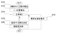
- FIG. 29 shows a flowchart of the destination setting process.
- the a-pin insertion holes 760a, the b-pin insertion holes 760b, the c-pin insertion holes 760c, and the d-pin insertion holes 760d are formed in a row at predetermined intervals from the bottom to the top.
- a flexible printed circuit (FPC) 754 is supported and fixed by a fixing portion 752 at an upper end portion in a region where the pin insertion hole 760 is formed.
- the fixing portion 752 is located above the d pin insertion hole 760 d. Furthermore, the lower end of the FPC 754 is located below the a-pin insertion hole 760a.
- An angle sensor 750 is provided near the lower end of the FPC 754.
- the angle sensor 750 is a three-axis sensor (three-dimensional angle sensor). As shown in FIG. 27, when the predetermined destination setting insertion pin 780 is inserted, the FPC 754 is pushed by the end of the destination setting insertion pin 780, and the angle sensor 750 is moved away from the inner wall surface of the cabinet. .
- the amount of movement of the angle sensor 750 that is, the separation distance differs depending on the pin insertion hole 760 into which the destination setting insertion pin 780 is inserted. For example, when inserted into the lowermost a-pin insertion hole 760a, the shortest separation distance Da is obtained.
- the separation distance becomes longer, and the longest d separation distance Dd is obtained in the top d pin insertion hole 760d.
- the FPC 754 is reinforced so as not to bend even when pressed by the destination setting insertion pin 780.
- the sensor detection unit 730 acquires the signal (X value, Y value, Z value) of the angle sensor 750, calculates the separation distance, and notifies the setting unit 40. Do.
- the setting unit 40 determines the destination to be set with reference to the country setting table shown in FIG. For example, when the pin position (pin insertion hole 760) is a (a pin insertion hole 760a), it is the separation distance Da and the destination is Malaysia. When the pin position (pin insertion hole 760) is c (c pin insertion hole 760c), it is the separation distance Dc and the destination is Australia.
- the signal of the angle sensor 750 for detecting the pin position is always inputted to the microcomputer on the television side constituting the sensor detection unit 730, for example, the signal result at the time of power activation or at constant intervals during operation
- the destination setting process is performed by executing the routine for confirming the.
- the sensor position becomes the default position, and it is possible to recognize that the model label 70 has been removed on the television side.
- the country selection screen is displayed so that the country selection can be newly reset when the power is turned on or in operation.
- the destination setting according to the pin position may be performed only at the initial stage of shipment after the final adjustment of the production factory. This is for attaching a model label 70, a serial number or the like as a finished product after the product confirmation is completed.
- the sensor detection unit 730 reads signals (X value, Y value, Z value) of three axes of the angle sensor 750 (S10).
- the setting unit 40 obtains the X value, Y value, and Z value from the sensor detection unit 730, compares predetermined reference values, detects an angle, and calculates the distance D from the inner wall surface of the cabinet 92. Then, the pin position is calculated (S12).
- the calculated pin position is a normal value (S14), and if it is a value that can not be originally calculated, it is determined that it is abnormal (N in S14), indicating that it is abnormal
- N in S14 the value that can not be originally calculated
- S16 the user or service representative is notified.
- the abnormality for example, it is assumed that the installation state is inclined.
- the setting unit 40 refers to the country setting table shown in FIG. 28 to determine the destination country corresponding to the pin position (S18), and various settings corresponding to the determined destination country. (Language etc.) is reflected on the liquid crystal television 710 (S20).
- the service representative can provide a function to detect that the model label 70 is peeled off so that it can be easily done, and a pinning location description for setting in each country is displayed. May be displayed. The service representative carries out the new country setting by pasting the model label 70 again according to the displayed instruction.
- FIG. 30 shows the appearance of a liquid crystal television 710a according to this embodiment, in particular, FIG. 30 (a) shows the back, and FIG. 30 (b) schematically shows the inner side of the side.
- the configuration for inserting the destination setting insertion pin 780 has been described.
- the contact surface becomes a point, and in the case of an FPC 754 or the like on which the angle sensor 750 is mounted, variations may occur in how it bends. Therefore, the contact area with the FPC 754 can be in contact with the surface (as wide as possible).
- the destination setting insertion pin 780 not the destination setting insertion pin 780 but the destination setting fitting part 785 configured with small parts such as plastic as the insertion member is fitted in the fitting groove 795 provided in the label attaching area 790a.
- the position of the angle sensor 750 is set to a desired position.
- the destination setting fitting part 785 is configured to be movable in the fitting groove 795 and can not be removed, and may be configured to be moved to a desired position by a service representative, or removed once. It may be configured to be snapped into a desired position.
- the destination setting fitting part 785 has a cross shape in front view, and the shape of the side inserted in the liquid crystal television 710a (the front side in the liquid crystal television 710a) is a slope where the lower side spreads It has become. That is, in the trapezoidal member in a side view, the trapezoidal legs on the television inner side are on the back side of the television toward the lower side, and the opposite legs are vertical. A horizontally extending part is formed in the vicinity of the trapezoidal vertical leg.
- a fitting groove 795 is formed in the label attaching area 790a, and the destination setting fitting part 785 can be fitted.
- four horizontal grooves are formed at equal intervals with respect to one vertical groove.
- the horizontal grooves are associated with symbols a to d in order from the bottom to correspond to the above-mentioned pin positions a to d.
- the destination setting fitting part 785 is fitted in the fitting groove 795 so that the horizontal part of the destination setting fitting part 785 fits in any of the four grooves.
- FIG. 31 shows the relationship between the fitting state of the destination setting fitting part 785 and the fitting groove 795 and the destination setting.
- the angle sensor 750 is at the position of the distance Da shown in FIG. 27 of the ninth embodiment and the destination is Malaysia.
- the angle sensor 750 becomes the position of the distance Dc shown in FIG. 27 and the destination becomes Australia.
- different parts 785a to 785d may be used for the destination setting fitting parts 785 depending on the destination.
- the contact surface with the FPC 754 can be set appropriately.
Landscapes
- Engineering & Computer Science (AREA)
- Physics & Mathematics (AREA)
- Computer Hardware Design (AREA)
- General Physics & Mathematics (AREA)
- Theoretical Computer Science (AREA)
- Multimedia (AREA)
- Signal Processing (AREA)
- Controls And Circuits For Display Device (AREA)
- Color Television Systems (AREA)
- Devices For Indicating Variable Information By Combining Individual Elements (AREA)
Abstract
表示出力装置において、簡易的な構成で仕向地設定を行うことが可能な技術を提供する。 液晶テレビ10のキャビネット92の背面94には、モデルラベル70を貼付する領域であるラベル貼付領域90が設けられている。ラベル貼付領域90は、共通化設計の全対象国、地域のサイズを考慮したモデルラベル70が貼付可能となっている。液晶テレビ10の組み立て時に、最終工程にて貼付されるモデルラベル70が、ラベル貼付領域90に貼付される。導通検知部30は、モデルラベル70で短絡されたラベル検出ピン50を検知し、設定部40は検知結果から仕向地に特定し閉仕向地に対応した設定を行う。
Description
本発明は、表示出力装置に係り、例えば、仕向地ごとに各種の設定が異なるテレビや録画再生装置等の表示出力装置に対する設定を行う機能を備えた表示出力装置に関する。
一般的に、アジア向けのテレビやDVDレコーダ等の表示出力等は、多くの国、地域を対象として設計されている。しかし、多地域共通設計製品がなされる場合が多く、その場合、テレビの初回起動時にユーザ自身で国・地域選択をしなければならない。ユーザにとって非常に煩わしい作業である。
仕向地にあわせて設定を行う技術には各種のものが提案されている。例えば、仕向け先別の何種類かの使用プログラムをマイコンに内蔵して、仕向け先別の入力データにより使用プログラムを選択するテレビの仕向け先仕様プログラムの選択方法において、リモコンにより行う技術がある(例えば、特許文献1参照)。この技術では、テレビセットに必ず装備されるリモコンの「電源ON」キーにより送信するリモコン送信データに、仕向け先別に予め決められた仕向け先コードを付加して送信する。テレビセットのマイコンが、受信するリモコン送信データから判別した仕向け先コードにより、仕向け先使用プログラムを選択する。
ところで、上述のように、購入後、国・地域選択を、複数の国・地域からユーザが選択する場合には、自国で販売されている製品にも関わらず、国・地域選択をする手間が生じる。また、複数表示された選択項目の中から選択する為、ユーザが自国専用モデルと感じる事は難しいという課題があり、マーケティング上の観点から訴求力の強化も求められていた。
特許文献1に開示の技術では、リモコン信号で仕向けを判別するには、判別するための国・地域分のリモコンを準備する必要があり、共通化できる設計部分をあえて分けて設計する必要があり、設計の効率や製造コストの観点から別の技術が求められていた。
本発明は以上のような状況に鑑みなされたものであって、上記課題を解決する技術を提供することを目的とする。
本発明の表示出力装置は、複数の被選択部と、前記被選択部を選択するシール部材と、選択された前記被選択部を検出する検出部と、検出状態に応じて設定を行う設定部と、を備える。
本発明の表示出力装置は、筐体において、ラベルが貼付される領域に設けられた複数の電極部と、前記ラベルの貼付面に設けられた導電パターンと、前記複数の電極部に接続され、前記ラベルが前記筐体に貼付され前記導電パターンによって導通されたピンの組み合わせを取得する導通検知部と、前記導通検知部の検知結果に応じた設定を行う設定部と、を備える。
また、前記ラベルは、仕向地毎に異なるモデルラベルであって、前記設定部は、前記導通検知部の前記検知結果に応じて言語設定を行ってもよい。
本発明の表示出力装置は、筐体内部において、移動可能に配置された角度センサと、ラベルが貼付される領域に形成された開口から挿入され前記角度センサの位置を移動させる挿入部材と、前記角度センサの位置を取得するセンサ検知部と、前記センサ検知部の検知結果に応じた設定を行う設定部とを備える。
本発明の表示出力装置は、筐体において、ラベルが貼付される領域に設けられた複数の電極部と、前記ラベルの貼付面に設けられた導電パターンと、前記複数の電極部に接続され、前記ラベルが前記筐体に貼付され前記導電パターンによって導通されたピンの組み合わせを取得する導通検知部と、前記導通検知部の検知結果に応じた設定を行う設定部と、を備える。
また、前記ラベルは、仕向地毎に異なるモデルラベルであって、前記設定部は、前記導通検知部の前記検知結果に応じて言語設定を行ってもよい。
本発明の表示出力装置は、筐体内部において、移動可能に配置された角度センサと、ラベルが貼付される領域に形成された開口から挿入され前記角度センサの位置を移動させる挿入部材と、前記角度センサの位置を取得するセンサ検知部と、前記センサ検知部の検知結果に応じた設定を行う設定部とを備える。
本発明によれば、表示出力装置において、簡易的な構成で各種の設定を行うことが可能な技術を提供することができる。
次に、本発明を実施するための形態(以下、単に「実施形態」という)を、図面を参照して具体的に説明する。ここでは表示出力装置として液晶テレビを例示するが、DVDレコーダやBDレコーダについても適用することができる。
<第1の実施形態>
図1は、本実施形態に係る液晶テレビ10の外観を示す図であり、図1(a)は正面図、図1(b)は背面図、図1(c)は断面図を示している。
図1は、本実施形態に係る液晶テレビ10の外観を示す図であり、図1(a)は正面図、図1(b)は背面図、図1(c)は断面図を示している。
液晶テレビ10は、背面94にラベル貼付領域90にモデルラベル70を貼付している。上述のように、液晶テレビ10の設計としては共通化設計を実施している場合でも、各国・地域毎に安全規格、人種による主使用言語が異なっている。そして、各安全マークが記載されているモデルラベル70については、各国の安全規格に基づいた表示内容になる。このため、各国毎に異なる種類のモデルラベル70を使用する必要がある。本実施形態では、省くことができないモデルラベル70を用いて、液晶テレビ10の仕向地設定を行う。
詳細は後述するが、液晶テレビ10は、モデルラベル70を仕向地毎に形状、または貼付位置を変えることにより、仕向けを自動選択する機能を有する。一般には、生産ラインの最終工程で、各仕向けに応じたモデルラベル70をキャビネット92の所定の領域に貼付しているが、モデルラベル70の形状、及び貼付位置を、各仕向け毎に変更する。
各仕向け毎に形状、又は張り付け位置の異なったモデルラベル70が貼られた状態で、生産ラインの最終工程で出荷状態に設定する際、つまり初回起動時に、モデルラベル70の形状、貼付位置に応じた導通回路が形成され、モデルラベル70の仕向けをマイコン(導通検知部30)に判別されることが可能となる。以下、詳細に説明する。なお、初回起動時とは、リセット後の最初の起動時も含むものである。
工場での生産最終工程(出荷設定時)にて、電源オン状態で、国・地域自動設定をモデルラベル70を用いた方法で行う。なお、出荷の際に、モデルラベル70を複数の仕向地向けに複数種類同梱することで、ユーザ又は販売店がモデルラベル70を貼り替え設定変更をすることも可能である。
図1(b)に示すモデルラベル70を貼付する領域であるラベル貼付領域90は、キャビネット92の背面94に設けられており、共通化設計の全対象国、地域のサイズを考慮したモデルラベル70が貼付可能となっている。
各国、地域にて、安全規格によりモデルラベルの表示が異なるため、地域によって複数の印刷内容に分かれたモデルラベル70が存在する。本実施形態では、液晶テレビ10の組み立て時に、最終工程にて貼付されるモデルラベル70が、ラベル貼付領域90に貼付される。さらに各国、地域ごとにモデルラベル70の形状、または貼付位置等を変更し、それらを液晶テレビ10で検出する。
図2は、液晶テレビ10の構成を示すブロック図であり、主に、仕向地設定の機能に着目して図示している。液晶テレビ10は、一般的な機能として、チューナ11と、コンテンツ処理部12と、表示出力部13と、音声出力部14と、操作制御部15とを備え、さらに、それら構成要素を統括的に制御する主制御部16を備える。これら構成要素は一般的なものであるので説明は省略する。
さらに、液晶テレビ10は、本実施形態で特徴的な仕向地設定機能を実現するための構成として、モデルラベル70、ラベル検出ピン50、導通検知部30及びラベル検出ピン50を備える。導通検知部30として、一般的なマイコン(MPU)を用いることができ、例えば主制御部16と共通に構成されてもよいし、独立して構成されてもよい。
ラベル検出ピン50は、キャビネット92の背面94に設けられたラベル貼付領域90に複数配置されている。モデルラベル70の貼付面には仕向地ごとに異なる導通部72が形成されている。モデルラベル70がラベル貼付領域90に貼付されると、導通部72によって二つのラベル検出ピン50が導通(短絡)する。導通検知部30は、どのラベル検出ピン50が導通したかを設定部40に通知する。設定部40は、仕向地対応テーブルを有しており、導通検知部30からの通知をもとに、仕向地対応テーブルを参照して、各種の設定、より具体的には、貼付されたモデルラベル70に対応する仕向地設定を行う。仕向地設定として、使用言語設定や、チューナ11の選局設定がある。なお、設定項目ごとにモデルラベル70を設けてもよい。
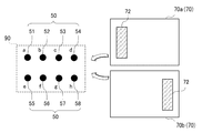
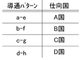
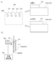
図3及び図4にラベル検出ピン50及びモデルラベル70の詳細を示す。また、図5に仕向地参照テーブルの例を示す。図3は、ラベル貼付領域90(ラベル検出ピン50)にモデルラベル70が貼付される前の状態を示しており、モデルラベル70としてA国仕向地用のモデルラベル70aとD国仕向地用のモデルラベル70bが示されている。いずれかがラベル貼付領域90に貼付される。
ラベル貼付領域90に配置されるラベル検出ピン50は、8個のa~hピン51~58から構成されている。8個のa~hピン51~58は、上下2段に配置されており、上段には図示で左側からa~dピン51~54が配置され、下段には左側からe~hピン55~58が配置されている。
そして、A国仕向地用のモデルラベル70aは、ラベル貼付領域90に適正に貼付されると、導通部72によりaピン51とeピン55とを短絡させる。D国仕向地用のモデルラベル70bは、ラベル貼付領域90に適正に貼付されると、導通部72によりdピン54とhピン58とを短絡させる。
図4(a)はラベル貼付領域90(ラベル検出ピン50)にモデルラベル70が貼付された状態の外観を示している。ここでは、A国仕向地用のモデルラベル70aが貼付されている。また図4(b)は、そのときの断面図を示している。なお、理解しやすいように、モデルラベル70aが背面94から若干離間して表記しているが、実際には一体となっている。
図示のように、導通部72によりaピン51とeピン55とが短絡している。そして、図4(b)に示すように、導通検知部30がaピン51とeピン55の短絡状態を検知し、検知結果を設定部40に通知する。設定部40は、導通検知部30から検知結果を取得すると、図5に示す仕向地参照テーブルを参照し、仕向地を特定し、特定された仕向地に対応する設定(例えば使用言語設定や選局設定等)を行う。
本実施形態によると、ユーザ等は、液晶テレビ10の購入後、初回起動時に例えば国選択をする手間を省くことができる。また、ユーザに複数の国・地域用に共通設計された商品であることが分かりにくくなり、ローカルフィット性を高めることができる。また、引っ越し等によって使用地域が異なった場合でも、設定変更が容易となる。つまり、モデルラベル70を別の種類に貼り替えることで対応することができる。
なお、設定部40は、初回電源オン時に自動的に設定を行うが、次回以降はユーザが設定画面を呼び出しユーザの操作に応じて行う。また、モデルラベル70が剥がれた場合などでは、ユーザに再設定を行ってもよいかの確認をしてもよいし、また、検知結果に変化があったことを認識したときに自動的に設定の変更を行ってもよい。
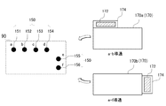
図6は、第1の実施形態の第1の変形例に係るラベル検出ピン150とモデルラベル170とを示している。図示のように、モデルラベル170は、導通部172が形成される構成として仕向地ごとに異なるタブ174を有する。ラベル検出ピン150として、上段に4つのa~dピン151~154が配置され、右側に上下にeピン155及びfピン156が配置されている。
そして、A国仕向地用のモデルラベル170aでは、図示で左上にタブ174が配置されている。ラベル貼付領域90にモデルラベル170aが貼付されると、aピン151とbピン152が短絡される。そして、モデルラベル170bでは、図示で右側にタブ174が配置されている。ラベル貼付領域90にモデルラベル170bが貼付されると、eピン155とfピン156が短絡される。
そして、上述同様に、導通検知部30が短絡状態を検知し、検知結果を設定部40に通知する。設定部40は、導通検知部30から検知結果を取得し、仕向地を特定し、特定された仕向地に対応する設定を行う。
なお、上記実施形態及び変形例では、対向するラベル検出ピン50または隣接するラベル検出ピン50を短絡したが、これに限る趣旨ではなく、例えば図3でaピン51とhピン58とを短絡させてもよく、設定部40の仕向地対応テーブルにそれに対応した仕向国を記述しておけばよい。
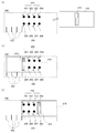
図7は、第1の実施形態の第2の変形例に係るラベル検出ピン250とモデルラベル270とを示している。図7(a)はモデルラベル270の貼付前の状態、図7(b)は仕向地をA国としてモデルラベル270を貼付した状態(aピン251とeピン254が短絡)、図7(c)は仕向地をD国としてモデルラベル270を貼付した状態(dピン255とhピン258が短絡)を示している。
図示のように、モデルラベル270は、導通部272が左右中央に縦長に形成される。ラベル検出ピン250として、図3と同様に上段に4つのa~dピン251~254が配置され、下段に4つのe~hピン255~258が配置されている。
さらにラベル検出ピン250の左下の領域には、モデルラベル270を配置する際の仕向地特定基準線292が形成されている。たとえば仕向地をA国に設定したい場合には、図7(b)に示すように、モデルラベル270の左端部を最も左側の仕向地特定基準線292に一致させて、モデルラベル270が貼付される。
そして、仕向地特定基準線292のそれぞれに仕向地等を明記しておけば、貼付ミスを防止することができる。
<第2の実施形態>
図8は、第2の実施形態に係るラベル検出ピン350及びモデルラベル370を示している。本実施形態では、導通部72による短絡を検知するのではなく、図8(a)に示すように、ラベル貼付領域390に設けられた4つの外光入射穴350(351~354)をモデルラベル370で塞ぐことで、仕向地を検出するものである。
図8は、第2の実施形態に係るラベル検出ピン350及びモデルラベル370を示している。本実施形態では、導通部72による短絡を検知するのではなく、図8(a)に示すように、ラベル貼付領域390に設けられた4つの外光入射穴350(351~354)をモデルラベル370で塞ぐことで、仕向地を検出するものである。
具体的には、モデルラベル370は、外光入射穴350(351~354)を塞ぐためのタブ374が設けられている。仕向地ごとにタブ374の大きさが設定されており、塞ぐことができる外光入射穴350(351~354)の数が異なる。例えば、図8(a)のA国仕向地用のモデルラベル370aのタブ374は、a外光入射穴351とb外光入射穴352を塞ぐことができる。B国仕向地用のモデルラベル370bのタブ374は、a外光入射穴351、b外光入射穴352及びc外光入射穴353を塞ぐことができる。
そして、キャビネット92(背面94)の内部に設けられたフォトセンサ335が外光入射穴350から入射する外光の取得し、光量検知部330がフォトセンサ335から出力される電圧値を元に検知された光量を算定し設定部40に通知する。設定部40は、光量と仕向地の対応関係が記載された仕向地テーブルを参照して、仕向地に対応した設定を行う。
外光入射穴350の形成方法としては、上記のモデルラベル370にタグ374を設定する方法に加え、外光入射穴350を仕向けに応じて削ったり、外光入射穴350を塞ぐために仕向けに応じて張り付け位置を変える、といった方法も採用することができる。
本実施形態でも、第1の実施形態同様の効果が得られる。
<第3の実施形態>
本実施形態では、第1の実施形態で示した構成を用いて、モデルラベル70を剥がされる、または意図的に剥がす場合等を想定して、ラベル貼付領域90でショートしていたラベル検出ピン50がオープンになった場合の遷移について効果的な処理を実現する。
本実施形態では、第1の実施形態で示した構成を用いて、モデルラベル70を剥がされる、または意図的に剥がす場合等を想定して、ラベル貼付領域90でショートしていたラベル検出ピン50がオープンになった場合の遷移について効果的な処理を実現する。
概要は次の通りである。
A.剥がした場合の動作形態:
(1)モデルラベル70がはがされても影響がないように、出荷設定時以外はピンショートによる自動仕向け設定を無効とする。
(2)モデルラベル70が剥がされた場合に、ユーザ、又はサービスマン等が新たに国選択を実施できるように、ラベル検出ピン50がすべてオープンの場合には、電源起動時に選択画面が表示される。
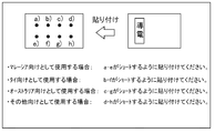
(3)モデルラベル70が剥がされた場合に、ユーザ、またはサービスマンが、新たに使用される国に合わせた選択が容易できるように、図9で示すような説明画面を表示出力部13で出力し、各国設定向けの貼り付け箇所説明を表示する。ユーザ等は、説明に従い、モデルラベル70を再度貼り付けすることにより、新たな国設定が実施される。
A.剥がした場合の動作形態:
(1)モデルラベル70がはがされても影響がないように、出荷設定時以外はピンショートによる自動仕向け設定を無効とする。
(2)モデルラベル70が剥がされた場合に、ユーザ、又はサービスマン等が新たに国選択を実施できるように、ラベル検出ピン50がすべてオープンの場合には、電源起動時に選択画面が表示される。
(3)モデルラベル70が剥がされた場合に、ユーザ、またはサービスマンが、新たに使用される国に合わせた選択が容易できるように、図9で示すような説明画面を表示出力部13で出力し、各国設定向けの貼り付け箇所説明を表示する。ユーザ等は、説明に従い、モデルラベル70を再度貼り付けすることにより、新たな国設定が実施される。
具体的な動作としては次の通りである。モデルラベル70によるラベル検出ピン50の検出結果は、常に液晶テレビ10のマイコン等によって構成されている導通検知部30に入力されているため、電源起動時、または動作時一定間隔にてこの導通検知部30の検出結果を確認する処理が実施される。これにより、ユーザ、又はサービスマン等が故意にラベルを剥がした際に、全てのラベル検出ピン50がオープンとなるため、液晶テレビ10側にてラベルが剥がされたことを認識することが可能となる。そして、モデルラベル70が剥がされた際の処理として、電源起動時、又は動作時に、新たに国選択を再設定できるように、国選択画面を表示する。
また、モデルラベル70が剥がされた際の処理として、電源起動時、又は動作時に、新たに国選択を再設定できるように、これらラベル検出ピン50の組合わせにより、どの国が選択されるのか、張り付け方法及び国選択の組み合わせを図9で示したような画面表示にて説明する機能を有してもよい。本機能により、説明に従い、モデルラベル70を再度貼り付けすることにより、ユーザ又はサービスマン等により、新たな国設定を容易に実施することが可能となる。
B.ユーザ設定により、設定からの復帰モードを個別に設ける形態:
(1)モデルラベル70を剥がさなくても、再度国設定が切り替えられるように、メニュー内に設定を設ける。
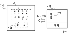
(2)図10に示すように、モデルラベル70のラベル検出ピン50の中で、検出を優先する、という設定ピン59y、59zを設けておき、この部分のみ剥がせるようなモデルラベル70の形状としておく。ここでは、モデルラベル70は、図10等に示した構成に対して、下側の領域に新たに導電の領域72xが選択的に分離可能(剥がすことが可能に)に設けられている。この「検出優先ピン(設定ピン59y、59z)」のピンショートが剥がされることにより、電源起動時に国選択画面が表示される。
(3)電源起動時に、USB端子に接続されたUSBメモリ内のデータを読み込み、データ内に特定の設定クリア用データが入っていた場合には、国設定がクリアされ、国選択画面が表示される。
(1)モデルラベル70を剥がさなくても、再度国設定が切り替えられるように、メニュー内に設定を設ける。
(2)図10に示すように、モデルラベル70のラベル検出ピン50の中で、検出を優先する、という設定ピン59y、59zを設けておき、この部分のみ剥がせるようなモデルラベル70の形状としておく。ここでは、モデルラベル70は、図10等に示した構成に対して、下側の領域に新たに導電の領域72xが選択的に分離可能(剥がすことが可能に)に設けられている。この「検出優先ピン(設定ピン59y、59z)」のピンショートが剥がされることにより、電源起動時に国選択画面が表示される。
(3)電源起動時に、USB端子に接続されたUSBメモリ内のデータを読み込み、データ内に特定の設定クリア用データが入っていた場合には、国設定がクリアされ、国選択画面が表示される。
本実施形態を導入することで、ユーザが液晶テレビ10を購入した後、または流通経路の変更により使用国が変更になった際に、容易に設定を変更することが可能となり、第1及び第2の実施形態において説明した、仕向け自動設定の設定方法に自由度を持たせることができる。
なお、上述の実施形態では、ラベル検出ピン50により設定する対象を国選択としているが、これに限る趣旨ではなく、その他に例えば、ユーザーモード(通常に用いられるモード)と、店頭モード(いわゆる店頭デモンストレーションモード)の切り替えに利用することとしてもよい。その場合、ラベル検出ピン50を導通させる手段としてモデルラベル70を利用しているが、店頭にて頻繁に使用される、POPラベルを利用してもよい。上記ユーザーモード、店頭モードの切り替えに対し、POPラベルを使用することにより、工場出荷時にはPOPラベルを貼り付けて出荷し、店頭展示時はPOPラベルを貼り付け、POPラベル裏側の導電部によりラベル検出ピン50をショートさせ、店頭モードとして動作する。店頭からユーザ宅に配荷される際には、店頭にてPOPラベルを廃止、又はユーザにPOPラベルを剥がすことを喚起し、POPラベルが剥がされ、検出ピンがオープンになることにより、ユーザーモードで動作する。
<第4の実施形態>
本実施形態では、モデルラベルに抵抗成分Rを有する構成となっている。
本実施形態では、モデルラベルに抵抗成分Rを有する構成となっている。
(1)液晶テレビ10の設計としては共通化設計を実施している事が多く、国・地域毎に安全規格や主使用言語が異なっている。そのため、安全マーク等が記載されるモデルラベル370cにおいては、各国の安全規格に基づいた表示内容になるため、各国毎に異なる種類のモデルラベル370を使用する必要がある。そこで、モデルラベル370cに抵抗値Rを持たせることで、仕向けを自動選択する機能を有することとする。
(2)生産ラインの最終工程で仕向け(販売国)に応じたモデルラベル370cをキャビネット92に貼り付けを実施している場合、モデルラベル370cに付加した抵抗値を仕向け毎に設定する。
(3)仕向け毎に抵抗値Rの異なったモデルラベルを貼り、液晶テレビ10の電源オン時にモデルラベル370cの抵抗値(ラベル抵抗RL(RA~RD等))に応じた電圧等の特性変化をマイコン等の導通検知部30に判別させ、仕向けを自動設定することが可能となる。例えば、図11では4カ国向けのモデルラベル370(370ca~370cd)を例示しており、オーストラリア向けのモデルラベル370caでは、抵抗値RAが設定されている。
(2)生産ラインの最終工程で仕向け(販売国)に応じたモデルラベル370cをキャビネット92に貼り付けを実施している場合、モデルラベル370cに付加した抵抗値を仕向け毎に設定する。
(3)仕向け毎に抵抗値Rの異なったモデルラベルを貼り、液晶テレビ10の電源オン時にモデルラベル370cの抵抗値(ラベル抵抗RL(RA~RD等))に応じた電圧等の特性変化をマイコン等の導通検知部30に判別させ、仕向けを自動設定することが可能となる。例えば、図11では4カ国向けのモデルラベル370(370ca~370cd)を例示しており、オーストラリア向けのモデルラベル370caでは、抵抗値RAが設定されている。
このような構成を用いることで、ユーザが液晶テレビ10を購入した後、初回起動時に国選択をする手間が省ける。また、ユーザに複数の国・地域用に共通設計された商品であることが分かりにくくなり、ローカルフィット性を高める。
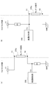
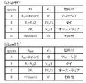
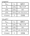
なお、図12は、モデルラベル検出回路のブロック図であり、図12(a)はハイサイド検出用の回路図で、図12(b)はローサイド検出用の回路図である。また、図13はラベル抵抗RLによる電圧変化及び仕向け例を示しており、図13(a)はハイサイド検出用、図13(b)はローサイド検出用である。
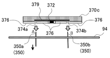
モデルラベル370cの裏側に、各仕向け地に対応する抵抗値RLを持たせ、ラベル貼付領域90に設けられている所定の二つのラベル検出ピン50(例えば、図中にてA,Bで表記するaピン51、bピン52)に接続する。上記二つのラベル検出ピン50(51、52)間の電圧等の変化を基板上に作成した検出回路(導通検知部30)で計測する。その電圧値から、予め導通検知部30(マイコン)の内部に記録されている各仕向け地に対応する抵抗値のテーブル(図13)を参照することで、貼りつけられたモデルラベル370の対応地域を判別することができる。
図14及び図15を参照して、モデルラベル370cへの抵抗値RLの実装方法を示す。図14はチップ素子抵抗を実装する場合を示し、図15はアキシャル抵抗を実装する場合を示している。
(1)モデルラベルに回路パターンを設け抵抗を実装する例:
図14(a)及び図15(a)に示すように、モデルラベル370cの背面に回路パターンを設け、各仕向け地に合わせた抵抗を付加する。図14(b)及び図15(b)は、A-B間(aピン51とbピン52間)を短絡することにより、図13に示すマレーシア向けの抵抗例を示している。同様に、RL1=RL2=R1とすると、並列接続である図14(c)及び図15(c)はRL=R1/2とタイ向けのラベル抵抗値を示し、直列接続である図14(d)及び図15(d)はRL=2×R1とオーストラリア向けの抵抗値を示す。
図14(a)及び図15(a)に示すように、モデルラベル370cの背面に回路パターンを設け、各仕向け地に合わせた抵抗を付加する。図14(b)及び図15(b)は、A-B間(aピン51とbピン52間)を短絡することにより、図13に示すマレーシア向けの抵抗例を示している。同様に、RL1=RL2=R1とすると、並列接続である図14(c)及び図15(c)はRL=R1/2とタイ向けのラベル抵抗値を示し、直列接続である図14(d)及び図15(d)はRL=2×R1とオーストラリア向けの抵抗値を示す。
また、図16に示すように、モデルラベル370c上に接続用のホール374a、374bを設け、ここにメイン基板から伸ばした接続ピンであるラベル検出ピン50を挿入することで、モデルラベル370cと検出回路(導通検知部30)が接続される。このとき、抵抗372の厚み分だけモデルラベル370cの裏面に凹凸が生じ、キャビネット92に貼り付けできない可能性がある為、接着材料376を用いて平坦化を図ることとする。
<第5の実施形態>
(2)回路パターンの長さによりモデルラベルへ抵抗値を付加する例:
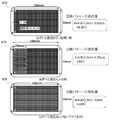
図17に回路パターンによるモデルラベル470への抵抗値実装の例を示す。回路パターンの抵抗値R(Ω)は、パターンに用いられる材料の抵抗率ρ(Ωm)、断面積S(m2)、長さL(m)より、以下の式(1)で与えられる。
R=ρL/S......................................................式(1)
(2)回路パターンの長さによりモデルラベルへ抵抗値を付加する例:
図17に回路パターンによるモデルラベル470への抵抗値実装の例を示す。回路パターンの抵抗値R(Ω)は、パターンに用いられる材料の抵抗率ρ(Ωm)、断面積S(m2)、長さL(m)より、以下の式(1)で与えられる。
R=ρL/S......................................................式(1)
モデルラベル470の裏面に十分なスペース(例として幅100mm、縦50mm)を設け、そのスペースに0.1mm間隔でパターンを形成する。その際パターンを形成する銅箔の厚さ0.035mm、幅0.1mmと断面積を一定にすることで、式(1)よりパターン長をパラメータとする。限られた面積においてパターン長を可能な限り長くする方法は、図17(b)や図17(c)のようにジグザグにパターンを形成する方法や、渦巻状にパターンを形成する方法など様々なパターンを採用することができる。このとき、図12に示した抵抗R1を60Ωとすることで、図17(b)では、図13に示すタイ向けの抵抗値を示す。また、図17(c)では、同様にオーストラリア向けの抵抗値を示す。また、図17(a)の回路パターンの抵抗値は、抵抗R1と比較して十分に小さいことから、0Ω(短絡)と近似でき、マレーシア向けの抵抗値を示す。
<第6の実施形態>
(3)モデルラベル内部に抵抗材料を付加する例:
図18はモデルラベル570として抵抗材料(抵抗材料部572)を付加して構成した例であって、図18(a)はハイサイド検出用の回路であり、図18(b)はローサイド検出用の回路を示す。また、図19はモデルラベル570の抵抗材料による電圧変化及び仕向地の例を示しており、図19(a)はハイサイド検出用、図19(b)はローサイド検出用である。
(3)モデルラベル内部に抵抗材料を付加する例:
図18はモデルラベル570として抵抗材料(抵抗材料部572)を付加して構成した例であって、図18(a)はハイサイド検出用の回路であり、図18(b)はローサイド検出用の回路を示す。また、図19はモデルラベル570の抵抗材料による電圧変化及び仕向地の例を示しており、図19(a)はハイサイド検出用、図19(b)はローサイド検出用である。
モデルラベル570は、印刷部577(絶縁体)、抵抗材料部572、接着部578、電極部574a、574bからなる。このモデルラベル570をキャビネット92に貼ることで、基板からの接続ピン550a、550bと接触する。
抵抗材料部572の抵抗材料を変えることで、電圧の変化を基板上に作成した検出回路(導通検知部530)で計測する。ここでは、図19のように抵抗材料A~Dを変化させることで仕向け設定を行う
導通検知部30は、入力される電圧値から、予め内部に記録されている図19に示すような各仕向け地に対応する抵抗値のテーブルを参照することで、貼りつけられたモデルラベル570の対応地域を判別することができる。
<第7の実施形態>
(4)モデルラベルの抵抗材料の面積を変える例:
上記(3)の例では、一定の面積で抵抗材料を変化させたが、ここでは、抵抗材料を1種類のみ使用し、図20に示す材料を付加する面積を変化させ、導通検知部530(マイコン)にかかる電圧値から、図21に示す予めマイコン内部に保管されている各仕向け地に対応する抵抗値のテーブルを参照することで、貼りつけられたモデルラベル570aの対応地域を判別することができる。
(4)モデルラベルの抵抗材料の面積を変える例:
上記(3)の例では、一定の面積で抵抗材料を変化させたが、ここでは、抵抗材料を1種類のみ使用し、図20に示す材料を付加する面積を変化させ、導通検知部530(マイコン)にかかる電圧値から、図21に示す予めマイコン内部に保管されている各仕向け地に対応する抵抗値のテーブルを参照することで、貼りつけられたモデルラベル570aの対応地域を判別することができる。
<第8の実施形態>
(5)モデルラベルに複数の抵抗成分を持たせる例:
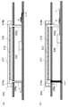
図22(a)~(c)に示すように、一つのモデルラベル670に複数の抵抗材料(例えば材料a、b、cの3種類)を持たせ、仕向け地ごとにモデルラベル670の貼り付け位置が、マレーシア向けでは貼付領域90の中央、タイ向けでは貼付領域90の左端、オーストラリア向けでは貼付領域90の右端というように指定されている。例えば、マレーシア向けの場合、材料bが検出ピンA、B(aピン51、bピン52)と接続し、マイコンにかかる電圧値から、例えば図23に示すような予めマイコン内部に記録されている各仕向け地に対応する抵抗値のテーブルを参照することで、貼りつけられたモデルラベル670の対応地域を判別することができる。
(5)モデルラベルに複数の抵抗成分を持たせる例:
図22(a)~(c)に示すように、一つのモデルラベル670に複数の抵抗材料(例えば材料a、b、cの3種類)を持たせ、仕向け地ごとにモデルラベル670の貼り付け位置が、マレーシア向けでは貼付領域90の中央、タイ向けでは貼付領域90の左端、オーストラリア向けでは貼付領域90の右端というように指定されている。例えば、マレーシア向けの場合、材料bが検出ピンA、B(aピン51、bピン52)と接続し、マイコンにかかる電圧値から、例えば図23に示すような予めマイコン内部に記録されている各仕向け地に対応する抵抗値のテーブルを参照することで、貼りつけられたモデルラベル670の対応地域を判別することができる。
<第9の実施形態>
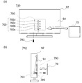
図24は本実施形態に係る液晶テレビ710の外観を示し、特に図24(a)は背面を示し、図24(b)は側面を内部状態を模式的にして示している。さらに、図25は、液晶テレビ710の機能ブロック図である。
図24は本実施形態に係る液晶テレビ710の外観を示し、特に図24(a)は背面を示し、図24(b)は側面を内部状態を模式的にして示している。さらに、図25は、液晶テレビ710の機能ブロック図である。
図24に示すように、本実施形態の液晶テレビ710では、モデルラベル70を貼り付けるためのラベル貼付領域790に、複数のピン挿入穴760(760a~760d)が設けられる。液晶テレビ710の内部に角度センサ750が配置され、ピン挿入穴760に挿入される仕向け設定用挿入ピン780(挿入部材)によって角度センサ750が所定の位置に移動される。移動後の角度センサ750の位置をセンサ検知部730が検知して、設定部40がその位置に応じた仕向地設定を行う。なお、センサ検知部730は、所定のマイコンによってその機能が実現され、単独で構成されてもよいし、他の機能と一緒に当該マイコンによって実現されてもよい。
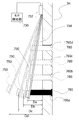
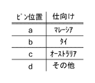
図26~図29を参照して詳細に説明する。図26は、ピン挿入穴760が設けられる領域の断面構造を模式的に示している。図27は、図26の構造において、仕向け設定用挿入ピン780が挿入された状態を模式的に示している。さらに、図28は仕向け設定用挿入ピン780が挿入される位置と仕向地の関係を示したテーブルを示している。さらにまた、図29は仕向地設定処理におけるフローチャートを示している。
主に図26及び図27に示すように、液晶テレビ710の背面94のキャビネットにおいて、ちょうどラベル貼付領域790に4つのピン挿入穴760が形成されている。具体的には、下から上に所定間隔でaピン挿入穴760a、bピン挿入穴760b、cピン挿入穴760c及びdピン挿入穴760dが一列に形成されている。
キャビネット内面には、ピン挿入穴760が形成される領域において、FPC(フレキシブルプリント基板)754が、上端部分で固定部752によって支持されて固定されている。固定部752は、dピン挿入穴760dよりも上に位置している。さらに、FPC754の下端は、aピン挿入穴760aよりも下に位置している。
そして、FPC754の下端近傍には、角度センサ750が設けられている。角度センサ750は三軸センサ(三次元角度センサ)である。図27に示すように、所定の仕向け設定用挿入ピン780が挿入されると、FPC754が仕向け設定用挿入ピン780の端部によって押され、角度センサ750がキャビネット内壁面から離間するように移動する。仕向け設定用挿入ピン780が挿入されるピン挿入穴760によって、角度センサ750の移動量、つまり離間距離が異なる。例えば、一番下のaピン挿入穴760aに挿入されたときには、一番短い離間距離Daとなる。仕向け設定用挿入ピン780が挿入されるピン挿入穴760の位置が上に行くにしたがい、離間距離が長くなり、一番上のdピン挿入穴760dでは一番長い離間距離Ddになる。なお、仕向け設定用挿入ピン780で押されてもFPC754は撓まないように補強されている。
離間距離によって角度センサ750の傾きが異なってくることから、センサ検知部730が角度センサ750の信号(X値、Y値、Z値)を取得し、離間距離を算出し、設定部40に通知する。設定部40は、図28に示す国設定テーブルを参照して設定すべき仕向地を決定する。例えば、ピン位置(ピン挿入穴760)がa(aピン挿入穴760a)の場合、離間距離Daであって仕向地がマレーシアである。ピン位置(ピン挿入穴760)がc(cピン挿入穴760c)の場合、離間距離Dcであって仕向地がオーストラリアである。
なお、ピン位置を検出するため角度センサ750の信号は、例えば常時にセンサ検知部730を構成するテレビ側のマイコンに入力されているため、電源起動時、または動作時一定間隔にてこの信号結果を確認するルーチンを実施することで、当該仕向地設定処理が実行される。これにより、ユーザ又はサービスマン等が故意にラベルを剥がした際に、センサ位置がデフォルト位置となるため、テレビ側にてモデルラベル70が剥がされたことを認識することが可能となる。この、モデルラベル70が剥がされた際の処理として、電源起動時、又は動作時に、新たに国選択を再設定できるように、国選択画面を表示する。
また、常にピン位置を検出し仕向け設定を実施する場合には、モデルラベル70をはがされた際の動作が不定となってしまうおそれがある。このため、生産工場の最終調整実施後出荷初期時のみ、ピン位置に応じた仕向け設定を実施してもよい。これは、製品確認完了後、完成品としてモデルラベル70、シリアルナンバー等を貼り付けるためである。
以上の構成による動作を図29のフローチャートを参照して纏めて説明する。
仕向地設定処理が開始されると、センサ検知部730は角度センサ750の3軸の信号(X値、Y値、Z値)を読み込む(S10)。
仕向地設定処理が開始されると、センサ検知部730は角度センサ750の3軸の信号(X値、Y値、Z値)を読み込む(S10)。
つづいて、設定部40がセンサ検知部730から上記X値、Y値、Z値を取得し、所定の基準値を比較して、角度を検出し、キャビネット92の内壁面からの距離Dを計算してピン位置を算出する(S12)。
ここで、算出したピン位置が正常値か否かを判断し(S14)、本来算出されないような値であれば異常であると判断し(S14のN)、異常である旨を表示等してユーザ又はサービス担当者に通知する(S16)。異常とは、例えば、設置状態が傾いていたりすることが想定される。
正常である場合(S14のY)、設定部40は図28に示した国設定テーブルを参照して、ピン位置に対応する仕向け国を決定し(S18)、決定した仕向け国に対応した各種設定(言語等)を液晶テレビ710に反映させる(S20)。
なお、上記構成の場合、ピン挿入穴760が4か所のため、デフォルト(ピン挿入無し)を含めて5カ国しか設定出来ない。そこで、ピンの長さを、複数種類用意し、ピン穴の間隔とピンの長さを適当に設定することで、同じ位置に角度センサ750が来ないようにすることで、より多くの仕向け設定が可能となる。
また、モデルラベル70が剥がされた場合には、サービス担当者が、容易にできるように、モデルラベル70の剥がされたことを検知する機能を設けると共に、各国設定向けのピン付け箇所説明が画面に表示されてもよい。サービス担当者は表示された説明に従い、モデルラベル70を再度貼り付けすることにより、新たな国設定が実施される。
<第10の実施形態>
図30は本実施形態に係る液晶テレビ710aの外観を示しており、特に図30(a)は背面を示し、図30(b)は側面を内部状態を模式的にして示している。第9の実施形態では、仕向け設定用挿入ピン780を挿入する構成について説明した。しかし、仕向け設定用挿入ピン780では、接触面が点になり、角度センサ750を乗せたFPC754などの場合、曲がり方にばらつきは生じる可能性がある。そこでFPC754との接触領域が面(極力広く)で接触できるようにする。
図30は本実施形態に係る液晶テレビ710aの外観を示しており、特に図30(a)は背面を示し、図30(b)は側面を内部状態を模式的にして示している。第9の実施形態では、仕向け設定用挿入ピン780を挿入する構成について説明した。しかし、仕向け設定用挿入ピン780では、接触面が点になり、角度センサ750を乗せたFPC754などの場合、曲がり方にばらつきは生じる可能性がある。そこでFPC754との接触領域が面(極力広く)で接触できるようにする。
そこで本実施形態では、挿入部材として、仕向け設定用挿入ピン780ではなく、プラスチック等のスモールパーツで構成した仕向け設定用嵌合パーツ785をラベル貼付領域790aに設けた嵌合溝795に嵌合させることで角度センサ750の位置を所望の位置に設定する。なお、仕向け設定用嵌合パーツ785は、嵌合溝795に移動可能であって取り外しができないように構成され、サービス担当者が所望の位置に移動させるように構成されてもよいし、一旦取り外した上で所望の位置にはめ込むように構成されてもよい。
具体的には、仕向け設定用嵌合パーツ785は、正面視で十字状の形状であって、液晶テレビ710aに挿入される側(液晶テレビ710aにおいては正面側)の形状は、下側が広がる斜面となっている。つまり、側面視で台形形状の部材において、テレビ内部側の台形の脚が下側ほどテレビ奥側になっており、反対の脚は垂直になっている。そして、台形の垂直の脚の近傍部分に水平方向に延びるパーツが形成されている。
一方、ラベル貼付領域790aには、嵌合溝795が形成されており、仕向け設定用嵌合パーツ785が嵌合可能になっている。具体的には、縦方向の1本の溝に対して4本の水平の溝が等間隔で形成されている。水平の溝は下から順にa~dの記号が対応づけられており、上述のピン位置a~dに対応するようになっている。仕向け設定用嵌合パーツ785の水平パーツが4本のいずれかの溝に嵌まるように、仕向け設定用嵌合パーツ785が嵌合溝795に嵌合される。
図31が仕向け設定用嵌合パーツ785と嵌合溝795の嵌合状態と仕向地設定との関係を示している。例えば、仕向け設定用嵌合パーツ785の水平パーツが溝aにはめ込まれている場合、角度センサ750が第9の実施形態の図27で示した距離Daの位置になり、仕向地がマレーシアとなる。また、仕向け設定用嵌合パーツ785の水平パーツが溝cにはめ込まれている場合、角度センサ750が図27で示した距離Dcの位置になり、仕向地がオーストラリアとなる。
本実施形態によると、生産ライン上で振動などでもFPC754の曲がり方の変化を抑えることが可能になる。
なお、図32に示すように、仕向け設定用嵌合パーツ785を仕向地ごとに異なるパーツ785a~785dが用いられてもよい。別パーツとすることで、FPC754との接触面を適切に設定することができる。
以上、本発明を実施形態をもとに説明した。この実施形態は例示であり、それらの各構成要素の組み合わせ等にいろいろな変形例が可能なこと、またそうした変形例も本発明の範囲にあることは当業者に理解されるところである。例えば、第1の実施形態と第9の実施形態とを合わせて実現される構成としてもよい。
10、710、710a 液晶テレビ
11 チューナ
12 コンテンツ処理部
13 表示出力部
14 音声出力部
15 操作制御部
16 主制御部
30 導通検知部
40 設定部
50、150、250 ラベル検出ピン
51、151、251 aピン
52、152、252 bピン
53、153、253 cピン
54、154,254 dピン
55、155、255 eピン
56、156、256 fピン
57、257 gピン
58、258 hピン
70、70a、70b、170、170a、170b、270、370、370a、37
0b、370c、370ca~cd、470、570、670 モデルラベル
72、172、272 導通部
90、190、290、390、790 ラベル貼付領域
92 キャビネット
94 背面
174、374 タブ
292 仕向地特定基準線
330 光量検知部
335 フォトセンサ
350 外光入射穴
351 a外光入射穴
352 b外光入射穴
353 c外光入射穴
354 d外光入射穴
376 接着材料
374a、374b ホール
574a、574b 電極部
730 センサ検知部
750 角度センサ
752 固定部
754 FPC
760 ピン挿入穴
760a aピン挿入穴
760b bピン挿入穴
760c cピン挿入穴
760d dピン挿入穴
780 仕向け設定用挿入ピン
785 仕向け設定用嵌合パーツ
785a~785d パーツ
795 嵌合溝
11 チューナ
12 コンテンツ処理部
13 表示出力部
14 音声出力部
15 操作制御部
16 主制御部
30 導通検知部
40 設定部
50、150、250 ラベル検出ピン
51、151、251 aピン
52、152、252 bピン
53、153、253 cピン
54、154,254 dピン
55、155、255 eピン
56、156、256 fピン
57、257 gピン
58、258 hピン
70、70a、70b、170、170a、170b、270、370、370a、37
0b、370c、370ca~cd、470、570、670 モデルラベル
72、172、272 導通部
90、190、290、390、790 ラベル貼付領域
92 キャビネット
94 背面
174、374 タブ
292 仕向地特定基準線
330 光量検知部
335 フォトセンサ
350 外光入射穴
351 a外光入射穴
352 b外光入射穴
353 c外光入射穴
354 d外光入射穴
376 接着材料
374a、374b ホール
574a、574b 電極部
730 センサ検知部
750 角度センサ
752 固定部
754 FPC
760 ピン挿入穴
760a aピン挿入穴
760b bピン挿入穴
760c cピン挿入穴
760d dピン挿入穴
780 仕向け設定用挿入ピン
785 仕向け設定用嵌合パーツ
785a~785d パーツ
795 嵌合溝
Claims (4)
- 複数の被選択部と、
前記被選択部を選択するシール部材と、
選択された前記被選択部を検出する検出部と、
検出状態に応じて設定を行う設定部と、
を備えることを特徴とする表示出力装置。 - 筐体において、ラベルが貼付される領域に設けられた複数の電極部と、
前記ラベルの貼付面に設けられた導電パターンと、
前記複数の電極部に接続され、前記ラベルが前記筐体に貼付され前記導電パターンによって導通された電極部の組み合わせを取得する導通検知部と、
前記導通検知部の検知結果に応じた設定を行う設定部と、
を備えることを特徴とする表示出力装置。 - 前記ラベルは、仕向地毎に異なるモデルラベルであって、
前記設定部は、前記導通検知部の前記検知結果に応じて言語設定を行うことを特徴とする請求項2に記載の表示出力装置。 - 筐体内部において、移動可能に配置された角度センサと、
ラベルが貼付される領域に形成された開口から挿入され前記角度センサの位置を移動させる挿入部材と、
前記角度センサの位置を取得するセンサ検知部と、
前記センサ検知部の検知結果に応じた設定を行う設定部と
を備えることを特徴とする表示出力装置。
Applications Claiming Priority (4)
| Application Number | Priority Date | Filing Date | Title |
|---|---|---|---|
| JP2012077597 | 2012-03-29 | ||
| JP2012-077597 | 2012-03-29 | ||
| JP2012156510A JP5205537B1 (ja) | 2012-03-29 | 2012-07-12 | 表示出力装置 |
| JP2012-156510 | 2012-07-12 |
Publications (1)
| Publication Number | Publication Date |
|---|---|
| WO2013145378A1 true WO2013145378A1 (ja) | 2013-10-03 |
Family
ID=48713071
Family Applications (1)
| Application Number | Title | Priority Date | Filing Date |
|---|---|---|---|
| PCT/JP2012/074348 Ceased WO2013145378A1 (ja) | 2012-03-29 | 2012-09-24 | 表示出力装置 |
Country Status (2)
| Country | Link |
|---|---|
| JP (1) | JP5205537B1 (ja) |
| WO (1) | WO2013145378A1 (ja) |
Citations (4)
| Publication number | Priority date | Publication date | Assignee | Title |
|---|---|---|---|---|
| JPH05146571A (ja) * | 1991-11-27 | 1993-06-15 | Janome Sewing Mach Co Ltd | 外部記憶装置のデータ識別選択装置 |
| JPH05300397A (ja) * | 1992-04-16 | 1993-11-12 | Funai Electric Co Ltd | テレビの仕向け先マイクロコンピュータ仕様の変更方法 |
| JP2011075854A (ja) * | 2009-09-30 | 2011-04-14 | Sharp Corp | 表示装置 |
| JP2011103500A (ja) * | 2009-11-10 | 2011-05-26 | Sharp Corp | 放送受信装置 |
-
2012
- 2012-07-12 JP JP2012156510A patent/JP5205537B1/ja not_active Expired - Fee Related
- 2012-09-24 WO PCT/JP2012/074348 patent/WO2013145378A1/ja not_active Ceased
Patent Citations (4)
| Publication number | Priority date | Publication date | Assignee | Title |
|---|---|---|---|---|
| JPH05146571A (ja) * | 1991-11-27 | 1993-06-15 | Janome Sewing Mach Co Ltd | 外部記憶装置のデータ識別選択装置 |
| JPH05300397A (ja) * | 1992-04-16 | 1993-11-12 | Funai Electric Co Ltd | テレビの仕向け先マイクロコンピュータ仕様の変更方法 |
| JP2011075854A (ja) * | 2009-09-30 | 2011-04-14 | Sharp Corp | 表示装置 |
| JP2011103500A (ja) * | 2009-11-10 | 2011-05-26 | Sharp Corp | 放送受信装置 |
Also Published As
| Publication number | Publication date |
|---|---|
| JP5205537B1 (ja) | 2013-06-05 |
| JP2013228661A (ja) | 2013-11-07 |
Similar Documents
| Publication | Publication Date | Title |
|---|---|---|
| US9752793B2 (en) | Self-setting circuit for an HVAC controller | |
| KR100654837B1 (ko) | 디스플레이장치의 제어방법 | |
| CN102371073A (zh) | 一种电子积木系统 | |
| CN202488619U (zh) | 一种硬件配置识别电路及机顶盒 | |
| EP2003531A2 (en) | Power supply control apparatus | |
| JP5577724B2 (ja) | 状態検出装置およびプログラム | |
| EP1739545A2 (en) | Detecting cable connection states | |
| WO2013145378A1 (ja) | 表示出力装置 | |
| EP2104065A1 (en) | Display apparatus and control method thereof | |
| US20080204269A1 (en) | Programmable remote control apparatus and method thereof | |
| JP6016309B2 (ja) | オーディオ/ビデオシステムを構成する作業者を支援するためのビデオディスプレイの実行方法 | |
| CN101977287A (zh) | 一种电视信源菜单上信号状态提示的方法 | |
| CN100527809C (zh) | 具有辅助接线功能的影音播放系统与方法 | |
| CN107863055B (zh) | 一种柔性基板及其状态检测方法、显示装置 | |
| JP4096971B2 (ja) | 制御機器及び制御システム | |
| TWI541660B (zh) | Function expansion method and device of electronic product | |
| JP2011259334A (ja) | 電子機器 | |
| CN101610369B (zh) | 一种平板电视机机芯 | |
| CN107835557A (zh) | 电路板、用于电路板进行程序选择的方法以及家用电器 | |
| CN103631383A (zh) | 电子设备及按键图标的显示方法 | |
| US20080060922A1 (en) | Modularized push button switch | |
| JP2003173851A (ja) | 接続検出用ジャックおよび電気機器 | |
| JP2011215465A (ja) | 電子装置 | |
| JP4921267B2 (ja) | コネクタおよび表示装置 | |
| US20080228953A1 (en) | Signal playback system with a dynamic wiring aid and method thereof |
Legal Events
| Date | Code | Title | Description |
|---|---|---|---|
| 121 | Ep: the epo has been informed by wipo that ep was designated in this application |
Ref document number: 12872369 Country of ref document: EP Kind code of ref document: A1 |
|
| NENP | Non-entry into the national phase |
Ref country code: DE |
|
| 122 | Ep: pct application non-entry in european phase |
Ref document number: 12872369 Country of ref document: EP Kind code of ref document: A1 |