WO2013145376A1 - 表示装置、および当該表示装置を備えた非接触給電システム、ならびに当該表示装置を備えたテレビジョン受像機 - Google Patents
表示装置、および当該表示装置を備えた非接触給電システム、ならびに当該表示装置を備えたテレビジョン受像機 Download PDFInfo
- Publication number
- WO2013145376A1 WO2013145376A1 PCT/JP2012/073725 JP2012073725W WO2013145376A1 WO 2013145376 A1 WO2013145376 A1 WO 2013145376A1 JP 2012073725 W JP2012073725 W JP 2012073725W WO 2013145376 A1 WO2013145376 A1 WO 2013145376A1
- Authority
- WO
- WIPO (PCT)
- Prior art keywords
- power
- handle
- angle
- display device
- power supply
- Prior art date
- Legal status (The legal status is an assumption and is not a legal conclusion. Google has not performed a legal analysis and makes no representation as to the accuracy of the status listed.)
- Ceased
Links
Images






Classifications
-
- H—ELECTRICITY
- H04—ELECTRIC COMMUNICATION TECHNIQUE
- H04N—PICTORIAL COMMUNICATION, e.g. TELEVISION
- H04N5/00—Details of television systems
- H04N5/63—Generation or supply of power specially adapted for television receivers
-
- H—ELECTRICITY
- H01—ELECTRIC ELEMENTS
- H01F—MAGNETS; INDUCTANCES; TRANSFORMERS; SELECTION OF MATERIALS FOR THEIR MAGNETIC PROPERTIES
- H01F38/00—Adaptations of transformers or inductances for specific applications or functions
- H01F38/14—Inductive couplings
-
- H—ELECTRICITY
- H02—GENERATION; CONVERSION OR DISTRIBUTION OF ELECTRIC POWER
- H02J—ELECTRIC POWER NETWORKS; CIRCUIT ARRANGEMENTS OR SYSTEMS FOR SUPPLYING OR DISTRIBUTING ELECTRIC POWER; SYSTEMS FOR STORING ELECTRIC ENERGY
- H02J50/00—Circuit arrangements or systems for wireless supply or distribution of electric power
- H02J50/005—Mechanical details of housing or structure aiming to accommodate the power transfer means, e.g. mechanical integration of coils, antennas or transducers into emitting or receiving devices
-
- H—ELECTRICITY
- H02—GENERATION; CONVERSION OR DISTRIBUTION OF ELECTRIC POWER
- H02J—ELECTRIC POWER NETWORKS; CIRCUIT ARRANGEMENTS OR SYSTEMS FOR SUPPLYING OR DISTRIBUTING ELECTRIC POWER; SYSTEMS FOR STORING ELECTRIC ENERGY
- H02J50/00—Circuit arrangements or systems for wireless supply or distribution of electric power
- H02J50/10—Circuit arrangements or systems for wireless supply or distribution of electric power using inductive coupling
-
- H—ELECTRICITY
- H02—GENERATION; CONVERSION OR DISTRIBUTION OF ELECTRIC POWER
- H02J—ELECTRIC POWER NETWORKS; CIRCUIT ARRANGEMENTS OR SYSTEMS FOR SUPPLYING OR DISTRIBUTING ELECTRIC POWER; SYSTEMS FOR STORING ELECTRIC ENERGY
- H02J50/00—Circuit arrangements or systems for wireless supply or distribution of electric power
- H02J50/80—Circuit arrangements or systems for wireless supply or distribution of electric power involving the exchange of data, concerning supply or distribution of electric power, between transmitting devices and receiving devices
-
- H—ELECTRICITY
- H02—GENERATION; CONVERSION OR DISTRIBUTION OF ELECTRIC POWER
- H02J—ELECTRIC POWER NETWORKS; CIRCUIT ARRANGEMENTS OR SYSTEMS FOR SUPPLYING OR DISTRIBUTING ELECTRIC POWER; SYSTEMS FOR STORING ELECTRIC ENERGY
- H02J50/00—Circuit arrangements or systems for wireless supply or distribution of electric power
- H02J50/90—Circuit arrangements or systems for wireless supply or distribution of electric power involving detection or optimisation of position, e.g. alignment
Definitions
- the present invention relates to a portable display device, a non-contact power supply system for charging the display device, and a television receiver including the display device.
- portable televisions In recent years, with the reduction in weight of television receivers, there is an increasing demand for portable television receivers (hereinafter referred to as portable televisions) that can be carried more easily and can be easily removed from the wall. As such a portable television, a model has been developed in which a battery is built in so that the power cord does not get in the way when being carried and the carrying is easier.
- Patent Document 1 discloses a non-contact power feeding system in which a portable television provided with a power receiving unit is attached to a power feeding unit attached to a floor, a wall, or the like, and power is fed from the power feeding unit to the portable television in a non-contact manner.
- power can be supplied to the portable television simply by attaching the portable television including the power receiving unit to the power feeding unit.
- the wiring of the power cord is not necessary, it is possible to suppress the wiring from becoming messy.
- One of the non-contact power feeding methods is an electromagnetic induction method.
- this electromagnetic induction method first, a high frequency magnetic field is generated by applying high frequency AC power to a power transmission coil of a power feeding unit. Then, when the power receiving coil of the power receiving unit is magnetically coupled to the power transmitting coil, AC power is induced in the power receiving coil by electromagnetic induction, so that power can be received from the power feeding unit in a non-contact manner.
- JP 2011-147513 A (published on August 4, 2011)”
- the mobile TV is thin, there is a high possibility that the receiving coil and the metal member are adjacent to each other inside the mobile TV.
- the metal member may resonate under the influence of the power receiving coil and may generate heat. Therefore, it is desirable to install the power receiving coil at a position where the metal member does not generate heat due to the influence of the power receiving coil.
- the present invention has been made in view of the above-described problems, and the object thereof is to ensure a sufficient space for installing a power receiving coil inside, and the metal member inside the power receiving power.
- An object of the present invention is to provide a portable display device that does not generate heat due to the influence of a coil, a non-contact power supply system including the display device, and a television receiver including the display device.
- a display device is a portable display device provided with a handle, wherein a non-contact power receiving coil is incorporated in the handle. It is a feature.
- the power receiving coil is incorporated in the handle of the display device.
- the power receiving coil is incorporated in the handle of the display device, and the space in the handle is effectively used. Therefore, it is not necessary to separately provide a space for installing the power receiving coil in the space in the display device, and the power receiving coil can be incorporated without any problem even in a thin display device.
- the handle can be designed in a desired structure regardless of the size and shape of the display device body. That is, even when the power receiving coil corresponding to the required transmission power is incorporated, the handle can be designed according to the power receiving coil to be incorporated.
- the power receiving coil is incorporated in the handle of the display device, a distance can be set between the power receiving coil and a metal member such as a backlight chassis inside the main body of the display device. As a result, heat generation of the metal member due to the power receiving coil can be minimized.
- a non-contact power feeding system is for the above-described display device, a power supply unit to which power is supplied from the outside, and non-contact power feeding to which power from the power source unit is supplied.
- the power feeding coil and the power receiving coil are magnetically coupled to each other, and the power is supplied to the power feeding device. Is characterized in that non-contact power is supplied to the display device.
- the display device it is possible to supply power to the display device in a non-contact manner using electromagnetic induction between the power transmission coil and the power reception coil.
- the power receiving coil is embedded in the handle of the display device, it is not necessary to separately provide a new member for non-contact power feeding, and even a thin display device can perform non-contact power feeding without any problem.
- a television receiver according to the present invention is characterized by including the above-described display device in order to solve the above-described problems.
- the space for installing a receiving coil inside can fully be ensured, and also the portable television receiver which an internal metal member does not generate
- the power receiving coil is incorporated in the handle of the display device, and the space in the handle is effectively utilized. Therefore, it is not necessary to separately provide a space for installing the power receiving coil in the space in the display device, and the power receiving coil can be incorporated without any problem even in a thin display device.
- the entire handle in which the power receiving coil is incorporated is not in contact with the main body of the display device, a distance is placed between the power receiving coil and a metal member such as a backlight chassis inside the main body of the display device. be able to. As a result, heat generation of the metal member due to the power receiving coil can be minimized.
- FIG. 1 It is a block diagram showing the whole composition of the non-contact electric supply system concerning one embodiment of the present invention. It is a figure which shows one application example of the non-contact electric power feeding method by an electromagnetic induction system. It is a figure which shows the state by which electric power is induced by a receiving coil, when a power transmission coil and a receiving coil couple
- (A) in a figure is a figure which shows the state which the non-contact electric power feeding system which concerns on one Embodiment of this invention is not supplying electric power
- (b) in the figure is the non-contact which concerns on one Embodiment of this invention It is a figure which shows the state which the electric power feeding system is supplying electric power.
- FIG. 1 It is a perspective view which shows the angle which concerns on one Embodiment of this invention. It is a figure which shows the back surface and side surface of the portable television which concerns on one Embodiment of this invention. It is a figure which shows the example of 1 arrangement
- (A) And (b) in a figure is a figure which shows the state in which the portable television which concerns on one Embodiment of this invention is hung on the angle. It is a flowchart which shows the electric power feeding method by the non-contact electric power feeding system which concerns on one Embodiment of this invention.
- (A) in a figure is a figure which shows the state in which the portable television which concerns on one Embodiment of this invention is not hung on an angle
- (b) in the figure is a portable television which concerns on one Embodiment of this invention. It is a figure which shows the state of the power transmission coil when a is not hung on an angle, and a receiving coil.
- (A) in a figure is a figure which shows the state in which the portable television which concerns on one Embodiment of this invention is hung on an angle
- (b) in the figure is a portable television which concerns on one Embodiment of this invention.
- It is a figure which shows the state of the power transmission coil and power receiving coil when is hung on an angle.
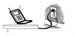
- FIG. 2 shows an application example of a non-contact power feeding method using an electromagnetic induction method.
- the mobile phone 13 as a power supply target is supplied with power from the power supply device 12 while being placed on the power supply device 12.
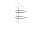
- the power feeding device 12 has a power transmission coil 16 as shown in FIG. 3, and the mobile phone 13 has a power reception coil 18 as shown in FIG.
- a high frequency magnetic field is generated by applying high frequency AC power to the power transmission coil 16.
- AC power is induced in the power receiving coil 18 by electromagnetic induction (dotted line in FIG. 3). Can be received in contact.
- the non-contact power feeding system uses such an electromagnetic induction type non-contact power feeding method.
- Non-contact power supply system 1 A non-contact power feeding system according to an embodiment of the present invention will be described in detail.
- the portable display device including the handle performs contactless power supply from the power supply device.
- the non-contact power feeding system 1 a case where the display device is a television receiver and the power feeding device is an angle for hanging the television receiver on a wall is taken as an example.
- the above-described television receiver and angle are merely examples, and the non-contact power feeding system 1 according to an embodiment of the present invention is not limited thereto.
- a display such as a personal computer can be applied as the display device, and a device designed only for supplying power to the display device, a rack on which the display device is mounted, or the like can be applied as the power supply device.
- FIG. 4 shows a schematic configuration of the non-contact power feeding system 1.
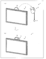
- 4A shows a state where the non-contact power supply system 1 is not supplying power
- FIG. 4B shows a state where the non-contact power supply system 1 is supplying power.
- the non-contact electric power feeding system 1 contains the portable television receiver 3 (henceforth a portable television) and the angle 2 attached to the wall.
- a handle 15 is attached to the mobile TV 3, and as shown in FIG. 4B, the mobile TV 3 can be hung on the angle 2 (wall) by attaching the handle 15 to the angle 2. It has become.
- the non-contact power supply system 1 power is supplied to the mobile TV 3 by the angle 2, but power is supplied depending on whether or not the mobile TV 3 is at a predetermined position close to the angle 2.
- the predetermined position is not particularly limited, but at least the angle 2 is a position where the portable television 3 can be contactlessly fed. In other words, any position where a later-described power transmission coil and power reception coil can be magnetically coupled may be used.
- FIG. 1 shows a block diagram of the overall configuration of a non-contact power feeding system 1 according to an embodiment of the present invention.
- the angle 2 includes a power supply substrate 4 (power supply unit), a non-contact power supply IF circuit 5 (power supply unit), a power transmission coil 6, a detection circuit 7 (detection unit), and a plug 11.
- the portable television 3 includes a power receiving coil 8, a non-contact power feeding IF circuit 9, and a battery 10. Note that the portable television 3 has various members for functioning as a television receiver, but in FIG. 1, only members related to non-contact power feeding are illustrated in order to simplify the drawing. Below, the angle 2 and the portable television 3 are demonstrated in order.
- the angle 2 includes a power supply substrate 4, a non-contact power feeding IF circuit 5, a power transmission coil 6 for non-contact power feeding, a detection circuit 7, and a plug 11.
- the plug 11 of the angle 2 is connected to an external power source such as an outlet and receives power from the external power source.
- the power supply board 4 is a board that is connected to the plug 11 and supplies the contactless power supply IF circuit 5 with the AC power obtained by converting the AC power obtained by the plug 11 from the external power source into DC power. .
- the non-contact power supply IF circuit 5 converts DC power into high frequency AC power and supplies the converted high frequency AC voltage to the power transmission coil 6. When a high-frequency AC voltage is supplied to the power transmission coil 6, a magnetic field is generated and the power transmission coil 6 and the power reception coil 8 are magnetically coupled.
- the angle 2 detection circuit 7 is a circuit that detects whether or not the portable television 3 is in a predetermined position close to the angle 2. Therefore, the detection circuit 7 detects whether or not the portable television 3 is hung on the angle 2. Although a specific detection method will be described later, the detection circuit 7 detects whether the mobile TV 3 is hung on the angle 2 and sends information on the detection result to the non-contact power supply IF circuit 5. .
- the contactless power supply IF circuit 5 based on information from the detection circuit 7, power is supplied to the power transmission coil 6 when the portable television 3 is hung on the angle 2, and when the portable television 3 is not hung on the angle 2. Power is not supplied to the power transmission coil 6. In this way, at the angle 2, power is supplied to the portable television 3 according to the detection result by the detection circuit 7.
- FIG. 5 shows a perspective view of the angle 2.
- the angle 2 has a structure for hanging the handle 15 of the portable television 3.
- An annular power transmission coil 6 is incorporated in the angle 2. Specifically, it is incorporated along the outer edge of the angle 2 as indicated by the dotted line shown in FIG.
- the portable television 3 includes a power receiving coil 8 for non-contact power feeding, a non-contact power feeding IF circuit 9, and a battery 10.
- a power receiving coil 8 for non-contact power feeding for non-contact power feeding
- a non-contact power feeding IF circuit 9 for non-contact power feeding
- a battery 10 for supplying AC power to the power transmission coil 6
- AC power is induced in the power reception coil 8 by electromagnetic induction.
- the AC power induced in the power receiving coil 8 is sent to the contactless power supply IF circuit 9, rectified into DC power in the contactless power supply IF circuit 9, and supplied to the battery 10.
- the electric power supplied to the battery 10 is supplied to various members for driving the portable television 3. In this way, the portable television 3 can receive power from the angle 2 in a contactless manner.
- FIG. 6 shows a rear view and a side view of the mobile TV 3.
- FIG. 7 shows an arrangement example of the mobile TV 3.
- the portable television 3 has a handle 15 for hanging the portable television 3 on the angle 2 on the back surface (the side opposite to the display surface).
- a bendable power receiving coil 8 is incorporated in the handle 15 in an annular shape. Specifically, it is incorporated along the shape of the handle 15 as shown by the dotted line in FIG. As described above, the power receiving coil 8 is incorporated in the handle 15 of the portable television 3 to effectively use the space in the handle 15. Therefore, it is not necessary to separately provide a space for installing the power receiving coil 8 in the space in the mobile TV 3, and the power receiving coil 8 can be incorporated without any problem even in the thin mobile TV 3.
- the power receiving coil 8 is incorporated in the handle 15, a distance can be set between the power receiving coil 8 and a metal member such as a backlight chassis inside the main body of the mobile TV 3. As a result, the heat generation of the metal member due to the power receiving coil 8 can be minimized.
- the handle 15 can be designed in a desired structure regardless of the size and shape of the main body of the portable television 3. That is, even when the power receiving coil 8 corresponding to the required transmission power is incorporated, the handle 15 can be designed according to the power receiving coil 8 to be incorporated.
- the handle 15 When carrying the mobile TV 3 and hanging it on the angle 2, the handle 15 protrudes above the upper end of the mobile TV 3 as shown in (a) of FIG. In this case, when viewing with the mobile TV 3 placed somewhere, the handle 15 may be seen from the viewer viewing the mobile TV 3, which may interfere with viewing.
- the power receiving coil 8 is a bendable coil. Therefore, the handle 15 can be bent as shown in FIG. As a result, the handle 15 can be made invisible to the viewer viewing the mobile TV 3, and does not interfere with viewing.
- examples of the bendable receiving coil 8 include a thin sheet coil.
- the handle 15 of the portable television 3 can be easily bent.
- the power receiving coil 8 is a sheet-like coil
- the power receiving coil 8 can be made thinner and lighter. Therefore, the handle 15 can be further downsized and the design of the portable television 3 can be improved.
- the sheet-like coil was mentioned as the receiving coil 8 which can be bent, it cannot be overemphasized that the receiving coil 8 is not necessarily limited to a sheet-like coil.
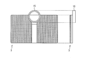
- FIG. 8 shows a positional relationship between the handle 15 and a metal member such as a backlight chassis in the main body of the mobile TV 3.
- a metal member such as a backlight chassis in the main body of the mobile TV 3.
- the rear surface of the mobile TV 3 is omitted for easy understanding of the positional relationship between the two.
- FIG. 8 shows a case where the handle 15 is provided at the center of the back surface of the mobile TV 3.
- a metal member such as a backlight chassis inside the main body of the mobile TV 3 is affected by the power receiving coil 8 incorporated in the handle 15. There is a risk of resonance and heat generation.
- FIG. 8 shows a case where the handle 15 is provided at a position where a part of the handle 15 protrudes above the upper end of the mobile TV 3.
- the entire handle 15 is not in contact with the main body of the mobile TV 3, and the area in contact with the main body of the mobile TV 3 is small as compared with the case of (a) in FIG. Therefore, under the influence of the power receiving coil 8 incorporated in the handle 15, the area where the metal member such as the backlight chassis in the main body of the portable television 3 resonates and generates heat is small. As a result, the heat generation of the metal member due to the power receiving coil 8 can be minimized.
- the power receiving coil 8 is annular (circular) because the power feeding efficiency is high.
- the present invention is not necessarily limited to this, and any shape can be used as long as the power receiving coil 8 has at least a loop shape and can be magnetically coupled to the power transmitting coil 6.
- FIG. 9 shows a rear view of the portable television 3 having the power receiving coil 8 in the shape of a square loop.
- the power receiving coil 8 may have a rectangular loop shape.
- it may be a polygonal loop shape or may be an elliptical loop shape. Since the power receiving coil 8 is a coil that can be bent, it can correspond to various shapes.
- FIG. 10 is a side view showing the angle 2.
- FIG. 11 is a diagram showing an internal configuration of the angle 2, in which (a) in the figure is a state in which the mobile TV 3 is not hung on the angle 2, and (b) is an angle 2 in the mobile TV 3. It is a figure of the state hung on.
- the detection method described below is merely an example, and the detection method by the detection circuit 7 is not limited to this.
- a switch 14 is attached to the angle 2 where the handle 15 of the portable TV 3 is hung.
- a pair of electrodes including a detection electrode 17 and a ground electrode 19 are provided inside the angle 2 with a space therebetween.
- the detection electrode 17 is connected to the detection circuit 7 and is in contact with the switch 14.
- the ground electrode 19 is grounded.
- a power source (not shown) passes a weak current through the detection electrode 17.
- the handle 15 pushes down the switch 14, so that the switch 14 is pushed into the angle 2 as shown in FIG.
- the switch 14 pushes down the detection electrode 17, and the detection electrode 17 contacts the ground electrode 19.
- the detection electrode 17 and the ground electrode 19 become conductive, and a current flows between the two electrodes.
- the detection circuit 7 detects that a current has flowed and determines that the portable television 3 is hung on the angle 2.
- FIG. 11A when the portable television 3 is not hung on the angle 2, the detection electrode 17 and the ground electrode 19 are not conductive, so that there is a current between the electrodes. Does not flow. Therefore, the detection circuit 7 does not detect the current and determines that the portable television 3 is not hung on the angle 2.
- the detection circuit 7 detects whether or not the portable television 3 is hung on the angle 2 until power is supplied to the portable television 3 according to the detection result.
- a typical flow will be described with reference to FIG. (A) and (b) in FIG. 12 are diagrams showing a state in which the portable television 3 is not hung on the angle 2, and (a) and (b) in FIG. It is a figure which shows the state hung on.
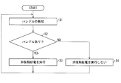
- FIG. 14 is a flowchart showing a power feeding method by the non-contact power feeding system 1.
- the detection circuit 7 for the angle 2 detects whether or not the portable television 3 is hung on the angle 2. Specifically, the detection circuit 7 detects whether or not the handle 15 is hung on the angle 2 (step 1; hereinafter abbreviated as S1). As shown in (a) of FIG. 12, when the viewer carries the portable television 3 and places it somewhere for viewing, the portable television 3 is not hung on the angle 2. Therefore, as shown in FIG. 12B, the handle 15 of the portable television 3 does not press the switch 14 attached to the angle 2, and no current flows between the detection electrode 17 and the ground electrode 19. As a result, the detection circuit 7 determines that the mobile TV 3 is not hung on the angle 2 (S2, NO).
- the contactless power supply IF circuit 5 does not supply power to the power transmission coil 6 based on information from the detection circuit 7. That is, non-contact power feeding to the portable television 3 is not performed (S4).
- the mobile TV 3 when the viewer views the mobile TV 3 while hanging on the wall, or when the mobile TV 3 is not viewed, the mobile TV 3 has an angle 2. It is hung on. Therefore, as shown in FIG. 13B, the handle 15 of the portable television 3 presses the switch 14 attached to the angle 2, and a current flows between the detection electrode 17 and the ground electrode 19. As a result, the detection circuit 7 determines that the mobile TV 3 is hung on the angle 2 (S2, YES).
- Information detected by the detection circuit 7 is sent to the contactless power supply IF circuit 5, and the contactless power supply IF circuit 5 supplies power to the power transmission coil 6 based on the information from the detection circuit 7. That is, non-contact power feeding to the portable television 3 is performed (S3).
- the process returns to S1 again, and the detection circuit 7 detects whether or not the handle 15 is hung on the angle 2, and repeats the processes after S2.
- the angle 2 is transferred to the mobile TV 3. Start non-contact power feeding.
- the angle 2 stops the non-contact power supply to the portable television 3. Therefore, the angle 2 performs non-contact power feeding while the detection circuit 7 detects that the handle 15 is hung on itself, and if the detection circuit 7 detects that the handle 15 is not hung on the angle 2, Stop contactless power supply.
- the detection circuit 7 also sends the information to the non-contact power supply IF circuit 5 even when it is determined that the handle 15 is not hung on the angle 2, but when the handle 15 is hung on the angle 2.
- the information may be sent to the non-contact power supply IF circuit 5 only when it is determined, and there is no particular limitation.
- the non-contact power supply IF circuit 5 may supply power to the power transmission coil 6 only when detection information is sent from the detection circuit 7.
- FIG. 15 is a diagram showing a state in which the mobile TV 3 is not hung on the angle 2
- (b) is a diagram showing the power transmission coil 6 and the power reception when the mobile TV 3 is not hung on the angle 2. It is a figure which shows the state of the coil.
- (a) in FIG. 16 is a diagram showing a state in which the mobile TV 3 is hung on the angle 2
- (b) is a power transmission coil 6 when the mobile TV 3 is hung on the angle 2.
- FIG. 6 is a diagram illustrating a state of the power receiving coil 8.
- the plug 11 of the angle 2 is connected to an external power source such as an outlet and receives power from the external power source.
- an exciting current i1 flows through the power transmission coil, and a magnetic flux ⁇ 1 is generated in the power transmission coil.
- the exciting current i1 at this time may be a weak current as long as it can excite the magnetic flux generated in the power receiving coil 8 in the handle 15 when the portable television 3 is hung on the angle 2.
- no voltage v2 is generated and no current flows (current i2 is approximately 0 amperes).
- the current detection circuit 21 detects that the current flowing through the power transmission coil 6 is less than a predetermined value, and determines that the portable television 3 is not hung on the angle 2.
- the predetermined value is a current value larger than the current i1.
- FIG. 16A when the portable television 3 is hung on the angle 2, as shown in FIG. 16B, the power receiving coil 8 in the handle 15 is passed through the power transmitting coil 8.
- the magnetic flux ⁇ 1 excited by 6 passes and a voltage v2 is generated in the power receiving coil.
- This voltage v2 causes a current i2 to flow through a load 20 such as an in-TV charging circuit connected to the power receiving coil 8.
- a reverse magnetic flux ⁇ ⁇ b> 2 is generated in the power receiving coil 8.
- the current detection circuit 21 detects that the current flowing through the power transmission coil 6 has increased, that is, the current flowing through the power transmission coil 6 has reached a predetermined value or more, it is determined that the portable television 3 is hung on the angle 2.
- FIG. 17 is a flowchart showing a power feeding method by the non-contact power feeding system 1.
- the current detection circuit 21 of angle 2 detects whether or not the portable television 3 is hung on the angle 2. Specifically, the current detection circuit 21 detects whether or not the current flowing through the power transmission coil 6 has increased (step 11; hereinafter abbreviated as S11). As shown in (a) of FIG. 16, when the viewer views the mobile TV 3 while hanging on the wall, or when the mobile TV 3 is not viewed, the mobile TV 3 is set to the angle 2. It is hung. Therefore, as shown in (b) of FIG. 16, the current flowing through the power transmission coil 6 is affected by the load current flowing through the power reception coil 8, so that the current flowing through the power transmission coil 6 becomes a predetermined value or more. . When the current detection circuit 21 detects that the current flowing through the power transmission coil 6 is equal to or greater than a predetermined value, it is determined that the mobile TV 3 is hung on the angle 2 (S12, YES).
- the information detected by the current detection circuit 21 is sent to the non-contact power supply IF circuit 5.
- the amount of power transmitted to the power receiving coil 8 is increased by increasing the current in the power transmitting coil 6 based on the information from the current detection circuit 21. That is, non-contact power feeding to the portable television 3 is performed (S13).
- the process returns to S11 again, and the current detection circuit 21 detects whether or not the handle 15 is hung on the angle 2 and repeats the processes after S12.
- the mobile TV 3 was placed somewhere (the state (a) in FIG. 15) and hung on the angle 2 (the state (a) in FIG. 16).
- the angle 2 starts non-contact power feeding to the portable television 3.
- the angle 2 is set to the mobile TV.
- the non-contact power supply to 3 is stopped. Therefore, the angle 2 performs non-contact power supply while the current detection circuit 21 detects that the handle 15 is hung on itself, and the current detection circuit 21 detects that the handle 15 is not hung on itself. If so, contactless power supply will be canceled.
- the current detection circuit 21 sends the information to the non-contact power supply IF circuit 5 even when it is determined that the handle 15 is not hung on the angle 2, but the handle 15 is hung on the angle 2.
- the information may be sent to the non-contact power supply IF circuit 5 only when it is determined that there is no particular limitation.
- the non-contact power supply IF circuit 5 may supply power to the power transmission coil 6 only when detection information is sent from the current detection circuit 21.
- the portable display device including the handle performs non-contact power feeding from the power feeding device.
- the contactless power supply system 1 according to the embodiment of the present invention has been described above by taking, as an example, the case where the display device is the portable television 3 and the power supply device is the angle 2 for hanging the portable television 3 on the wall.
- the non-contact power feeding system 1 according to an embodiment of the present invention is not limited to this.
- the contactless power feeding in the contactless power feeding system 1 according to the embodiment of the present invention is not limited to the case where the display device (mobile TV 3) is hung on the power feeding device (angle 2). Absent.
- the display device is a portable display device having a handle, and a power receiving coil for non-contact power feeding is incorporated in the handle. It is characterized by being.
- the power receiving coil is incorporated in the handle of the display device.
- the power receiving coil is incorporated in the handle of the display device, and the space in the handle is effectively used. Therefore, it is not necessary to separately provide a space for installing the power receiving coil in the space in the display device, and the power receiving coil can be incorporated without any problem even in a thin display device.
- the handle can be designed in a desired structure regardless of the size and shape of the display device body. That is, even when the power receiving coil corresponding to the required transmission power is incorporated, the handle can be designed according to the power receiving coil to be incorporated.
- the power receiving coil is incorporated in the handle of the display device, a distance can be set between the power receiving coil and a metal member such as a backlight chassis inside the main body of the display device. As a result, heat generation of the metal member due to the power receiving coil can be minimized.
- the power receiving coil is in a loop shape.
- the power receiving coil is circular, elliptical, or polygonal looped.
- the power receiving coil is a bendable coil.
- the power receiving coil is a bendable coil, the power receiving coil can be incorporated into the handle of the display device without any problem.
- the power receiving coil is a sheet-like coil.
- the handle can be easily bent. Furthermore, when the power receiving coil is a sheet-like coil, the power receiving coil can be made thinner and lighter. Therefore, the handle can be further miniaturized and the design of the display device can be improved.
- the handle is provided in a position where a part of the handle protrudes above the upper end portion of the display device.
- the handle of the display device protrudes above the upper end of the display device, the area where a part of the handle is in contact with the main body of the display device is small. Therefore, under the influence of the power receiving coil incorporated in the handle, the area where the metal member such as the backlight chassis inside the main body of the display device resonates and generates heat is small. As a result, heat generation of the metal member due to the power receiving coil can be minimized.
- the handle by making the power receiving coil a bendable coil. As a result, it is possible to make the handle invisible to the viewer viewing the display device, and this does not interfere with viewing.
- a non-contact power feeding system includes any one of the display devices described above, a power supply unit to which power is supplied from the outside, and a non-power supply from the power supply unit.
- a power feeding device including a power feeding coil for contact power feeding, and the power feeding coil and the power receiving coil are magnetically coupled when the handle is at a predetermined position close to the power feeding device. The power is supplied to the display device in a non-contact manner.
- the display device it is possible to supply power to the display device in a non-contact manner using electromagnetic induction between the power transmission coil and the power reception coil.
- the power receiving coil is embedded in the handle of the display device, it is not necessary to separately provide a new member for non-contact power feeding, and even a thin display device can perform non-contact power feeding without any problem.
- the power supply device further includes a detection unit that detects whether the handle is in the predetermined position, and the power supply unit includes the detection unit, When it is detected that the handle is in the predetermined position, the power is supplied to the power transmission coil. When the detection unit detects that the handle is not in the predetermined position, the power is supplied to the power transmission coil. It is characterized by not.
- the power feeding device performs non-contact power feeding while the detection unit detects that the handle is in a predetermined position, and if the detection unit detects that the handle is not in the predetermined position. Stop contactless power supply. Therefore, contactless power feeding can be performed on the display device only while the handle is in a predetermined position.
- the power feeding device is an angle attached to a wall, the handle can be hung on the angle, and the predetermined position is determined by the handle. It is characterized by being hung on an angle.
- the display device can be hung on the wall.
- the angle performs non-contact power supply while the detection unit detects that the handle is hung on itself, and stops contactless power supply if the detection unit detects that the handle is not hung on itself. . Therefore, non-contact power feeding can be performed on the display device only while the display device is hung on the angle.
- the power feeding device is an angle attached to a wall, the handle can be hung on the angle, and the predetermined position is determined by the handle.
- the angle is provided with a switch, and the detection unit detects that the handle is depressed when the handle is depressed on the switch. Detecting that the handle is hung on an angle, and detecting that the handle is not hung on the angle if the handle does not press the switch provided on the angle. It is said.
- the power feeding device performs non-contact power feeding while the detection unit detects that the handle is in an angled state, and the handle is not in an angled state. If the detection unit detects this, the non-contact power feeding is stopped. Therefore, it is possible to perform non-contact power feeding to the display device only while the handle is hung on the angle.
- a weak current is passed through the power transmission coil, and the detection unit has a predetermined value in which the magnitude of the current flowing through the power transmission coil is larger than the weak current.
- the detection unit can detect whether or not the handle is in a predetermined position without using a switch or the like.
- a television receiver according to the present invention is characterized by including any of the display devices described above in order to solve the above-described problems.
- the space for installing a receiving coil inside can fully be ensured, and also the portable television receiver which an internal metal member does not generate
- the non-contact power feeding system according to the present invention is applicable to a portable television receiver and an angle installed to hang the television receiver on a wall.
Landscapes
- Engineering & Computer Science (AREA)
- Power Engineering (AREA)
- Computer Networks & Wireless Communication (AREA)
- Multimedia (AREA)
- Signal Processing (AREA)
- Charge And Discharge Circuits For Batteries Or The Like (AREA)
- Secondary Cells (AREA)
Abstract
テレビジョン受像機(3)は、図示しないハンドルを備えた持ち運び可能なテレビジョン受像機であって、ハンドルの内部に、非接触給電用の受電コイル(8)が組み込められていることを特徴としている。
Description
本発明は、持ち運び可能な表示装置、および当該表示装置を充電するための非接触給電システム、ならびに当該表示装置を備えたテレビジョン受像機に関する。
近年ではテレビジョン受像機の軽量化に伴い、より簡単に持ち運べることができ、壁への取り外しが簡単な携帯型テレビジョン受像機(以下、携帯テレビと称す)の需要が高まりつつある。このような携帯テレビとして、バッテリを内蔵することによって、持ち運び時に電源コードが邪魔にならず、持ち運びがより容易にできる機種も開発されている。
従来ではバッテリ内蔵の電子機器の充電には電源コードを用いていたが、現在では電源コードを用いずに電力を供給する非接触給電システムが注目されている。例えば、特許文献1には、床や壁等に取り付けられた給電部に、受電部を備えた携帯テレビを取り付け、給電部から携帯テレビに非接触で給電する非接触給電システムが開示されている。これによって、受電部を備えた携帯テレビを給電部に取り付けるだけで携帯テレビに対して給電を行うことができる。また、電源コードの配線が不要になるから、配線が乱雑になるのを抑制することもできる。
この非接触給電方法の1つに電磁誘導方式がある。この電磁誘導方式では、まず給電部が有する送電コイルに高周波交流電力を印加することによって、高周波磁界を発生させる。そして、受電部が有する受電コイルを送電コイルに磁気的に結合させると、電磁誘導により受電コイルに交流電力が誘起されるので、給電部から電力を非接触で受け取ることができる。
上述した電磁誘導方式では、携帯テレビの内部に受電コイルを設置するための空間を確保する必要がある。ここで、近年では携帯テレビは薄型化しているため、薄型の携帯テレビにおいて受電コイルを設置するための空間の確保は取り分け重要な課題になっている。
また、携帯テレビが薄型であると、携帯テレビの内部で受電コイルと金属製の部材とが隣接する可能性が高くなる。この場合、受電コイルの影響を受けて金属製の部材が共振し、発熱する虞がある。したがって、受電コイルの影響を受けて金属製の部材が発熱しないような位置に受電コイルを設置することが望まれる。
そこで、本発明は上記の課題に鑑みてなされたものであり、その目的は、内部に受電コイルを設置するための空間を十分に確保することができ、なおかつ、内部の金属製の部材が受電コイルの影響を受けて発熱しない持ち運び可能な表示装置、および当該表示装置を備えた非接触給電システム、ならびに当該表示装置を備えたテレビジョン受像機を提供することにある。
本発明に係る表示装置は、上記の課題を解決するために、ハンドルを備えた持ち運び可能な表示装置であって、上記ハンドルの内部に、非接触給電用の受電コイルが組み込められていることを特徴としている。
上記の構成によれば、受電コイルは表示装置のハンドルの内部に組み込められている。このように、受電コイルを表示装置のハンドルに組み込み、ハンドル内の空間を有効活用している。そのため、表示装置内の空間に受電コイルを設置する空間を別途設ける必要がなく、薄型の表示装置でも何ら問題なく受電コイルを組み込むことができる。
また、ハンドルの構造のみを任意に設計できるようにしておくことによって、表示装置本体のサイズおよび形状に左右されずに、ハンドルを所望の構造に設計することができる。すなわち、必要な伝送電力に応じた受電コイルを組み込む場合でも、組み込む受電コイルに応じて、ハンドルを設計することができる。
さらに、受電コイルは表示装置のハンドルに組み込められているため、表示装置の本体内部にあるバックライトシャーシ等の金属部材と、受電コイルとの間に距離を置くことができる。結果、受電コイルに起因した金属部材の発熱を最小限に抑えることが可能となる。
本発明に係る非接触給電システムは、上記の課題を解決するために、上述した表示装置と、外部から電力が供給される電源部と、上記電源部からの電力が供給される非接触給電用の送電コイルとを備えた給電装置とを備え、上記ハンドルが、上記給電装置に近接した所定の位置にある場合に、上記送電コイルと上記受電コイルとが磁気的に結合することによって、上記電力を上記表示装置に非接触給電することを特徴としている。
上記の構成によれば、送電コイルと受電コイルとの間の電磁誘導を利用して、表示装置に対して非接触で給電することができる。特に受電コイルは表示装置のハンドルの内部に埋め込められているため、非接触給電のための新たな部材を別途設ける必要がなく、薄型の表示装置でも何ら問題なく非接触給電を行うことができる。
また、本発明に係るテレビジョン受像機は、上記の課題を解決するために、上述した表示装置を備えていることを特徴としている。
上記の構成よれば、内部に受電コイルを設置するための空間を十分に確保することができ、なおかつ、内部の金属製の部材が受電コイルの影響を受けて発熱しない持ち運び可能なテレビジョン受像機が得られる。
本発明の他の目的、特徴、および優れた点は、以下に示す記載によって十分分かるであろう。また、本発明の利点は、添付図面を参照した次の説明で明白になるであろう。
本発明によれば、受電コイルを表示装置のハンドルに組み込み、ハンドル内の空間を有効活用している。そのため、表示装置内の空間に受電コイルを設置する空間を別途設ける必要がなく、薄型の表示装置でも何ら問題なく受電コイルを組み込むことができる。
また、受電コイルが組み込められているハンドル全体が表示装置の本体と接しているわけではないため、表示装置の本体内部にあるバックライトシャーシ等の金属部材と、受電コイルとの間に距離を置くことができる。結果、受電コイルに起因した金属部材の発熱を最小限に抑えることが可能となる。
本発明を以下の実施の形態により詳細に説明する。なお、以下の説明においては、同一の機能および作用を示す部材については、同一の符号を付し、説明を省略する。
(電磁誘導方式の非接触給電方法)
本発明の一実施形態に係る非接触給電システムについて説明する前に、本発明の一実施形態に係る非接触給電システムにおいて用いる給電方法について簡単に説明する。本発明の一実施形態に係る非接触給電システムでは、電磁誘導方式の非接触給電方法を用いる。図2に、電磁誘導方式による非接触給電方法の一適用例を示す。
本発明の一実施形態に係る非接触給電システムについて説明する前に、本発明の一実施形態に係る非接触給電システムにおいて用いる給電方法について簡単に説明する。本発明の一実施形態に係る非接触給電システムでは、電磁誘導方式の非接触給電方法を用いる。図2に、電磁誘導方式による非接触給電方法の一適用例を示す。
図2に示すように、給電対象である携帯電話機13は、給電装置12の上に載せられた状態で給電装置12から給電されている。具体的には、給電装置12は図3に示すような送電コイル16を有しており、携帯電話機13は図3に示すような受電コイル18を有している。電磁誘導方式による非接触給電では、送電コイル16に高周波交流電力を印加することによって、高周波磁界を発生させる。そして、受電コイル18を送電コイル16に磁気的に結合させると、電磁誘導により受電コイル18に交流電力が誘起されるので(図3中の点線)、携帯電話機13は給電装置12から電力を非接触で受け取ることができる。本発明の一実施形態に係る非接触給電システムは、このような電磁誘導方式の非接触給電方法を利用している。
(非接触給電システム1)
本発明の一実施形態に係る非接触給電システムについて詳細に説明する。本発明の一実施形態に係る非接触給電システムでは、ハンドルを備えた持ち運び可能な表示装置に、給電装置から非接触給電を行う。以下では、本発明の一実施形態に係る非接触給電システム1について、表示装置がテレビジョン受像機であり、給電装置がテレビジョン受像機を壁に掛けるためのアングルである場合を例に挙げて説明する。なお、上記のテレビジョン受像機およびアングルはあくまでも一例であり、本発明の一実施形態に係る非接触給電システム1はこれに限定されるわけではない。例えば、表示装置としてはパーソナルコンピュータ等のディスプレイも適用可能であり、給電装置としては表示装置に給電するためのみに設計された装置や表示装置を載せるラック等も適用可能である。
本発明の一実施形態に係る非接触給電システムについて詳細に説明する。本発明の一実施形態に係る非接触給電システムでは、ハンドルを備えた持ち運び可能な表示装置に、給電装置から非接触給電を行う。以下では、本発明の一実施形態に係る非接触給電システム1について、表示装置がテレビジョン受像機であり、給電装置がテレビジョン受像機を壁に掛けるためのアングルである場合を例に挙げて説明する。なお、上記のテレビジョン受像機およびアングルはあくまでも一例であり、本発明の一実施形態に係る非接触給電システム1はこれに限定されるわけではない。例えば、表示装置としてはパーソナルコンピュータ等のディスプレイも適用可能であり、給電装置としては表示装置に給電するためのみに設計された装置や表示装置を載せるラック等も適用可能である。
図4に、非接触給電システム1の概略構成を示す。図4中の(a)には、非接触給電システム1が給電していない状態を示しており、(b)には、非接触給電システム1が給電している状態を示している。図4中の(a)に示すように、非接触給電システム1は、持ち運び可能なテレビジョン受像機3(以下、携帯テレビと称す)と、壁に取り付けられたアングル2とを含む。携帯テレビ3にはハンドル15が取り付けられており、図4中の(b)に示すように、ハンドル15をアングル2に取り付けることによって、携帯テレビ3をアングル2(壁)に掛けることが可能になっている。非接触給電システム1では、アングル2によって携帯テレビ3への給電が行われるが、携帯テレビ3がアングル2に近接した所定の位置にあるか否かに応じて給電が行われる。上記の所定の位置には特に限定はないが、少なくともアングル2が携帯テレビ3に非接触給電を行うことができる位置である。すなわち、後述する送電コイルと受電コイルとが磁気的に結合できる位置であればよい。
以下では、携帯テレビ3がアングル2に掛けられている状態が、上記の所定の位置であると想定して説明する。したがって、図4中の(a)のように携帯テレビ3がアングル2に取り付けられていない状態では、アングル2から携帯テレビ3への給電は行われない。一方、図4中の(b)のように携帯テレビ3がアングル2に取り付けられている状態では、アングル2から携帯テレビ3への給電が行われる。このように、アングル2では、アングル2に携帯テレビ3が掛けられているか否かに応じて、携帯テレビ3への給電を行う。
本発明の一実施形態に係る非接触給電システム1の全体構成のブロック図を図1に示す。図1に示すように、アングル2は、電源基板4(電源部)、非接触給電IF回路5(電源部)、送電コイル6、検知回路7(検知部)、およびプラグ11を有している。一方、携帯テレビ3は、受電コイル8、非接触給電IF回路9、およびバッテリ10を有している。なお、携帯テレビ3は、テレビジョン受像機として機能するための各種部材を有しているが、図1では図を簡略化するために、非接触給電に関わる部材のみを図示している。以下に、アングル2および携帯テレビ3について順に説明する。
(アングル2)
図1に示したように、アングル2は、電源基板4、非接触給電IF回路5、非接触給電用の送電コイル6、検知回路7、およびプラグ11を有している。アングル2のプラグ11はコンセント等の外部電源に接続されており、外部電源から電力を得ている。電源基板4は、プラグ11に接続された基板であって、プラグ11が外部電源から得た交流電力を直流電力に変換したものを非接触給電IF回路5に対して供給するための基板である。非接触給電IF回路5は、直流電力を高周波交流電力に変換し、変換した高周波交流電圧を送電コイル6に供給する。送電コイル6に高周波交流電圧が供給されると、磁界が発生して送電コイル6と受電コイル8とが磁気的に結合する。
図1に示したように、アングル2は、電源基板4、非接触給電IF回路5、非接触給電用の送電コイル6、検知回路7、およびプラグ11を有している。アングル2のプラグ11はコンセント等の外部電源に接続されており、外部電源から電力を得ている。電源基板4は、プラグ11に接続された基板であって、プラグ11が外部電源から得た交流電力を直流電力に変換したものを非接触給電IF回路5に対して供給するための基板である。非接触給電IF回路5は、直流電力を高周波交流電力に変換し、変換した高周波交流電圧を送電コイル6に供給する。送電コイル6に高周波交流電圧が供給されると、磁界が発生して送電コイル6と受電コイル8とが磁気的に結合する。
アングル2の検知回路7は、携帯テレビ3がアングル2に近接した所定の位置にあるか否かを検知する回路である。したがって、検知回路7はアングル2に携帯テレビ3が掛けられているか否かを検知する。具体的な検知方法について後述するが、検知回路7は、携帯テレビ3がアングル2に携帯テレビ3が掛けられているか否かを検知し、その検知結果の情報を非接触給電IF回路5に送る。非接触給電IF回路5では、検知回路7からの情報に基づき、携帯テレビ3がアングル2に掛けられている時には送電コイル6に電力を供給し、携帯テレビ3がアングル2に掛けられていない時には送電コイル6に電力を供給しない。このようにして、アングル2では、検知回路7による検知結果に応じて、携帯テレビ3への給電を行っている。
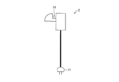
図5に、アングル2の斜視図を示す。図5に示すように、アングル2は、携帯テレビ3のハンドル15を掛けるための構造を有している。アングル2の内部には、環状の送電コイル6が組み込められている。具体的には、図5に示した点線のように、アングル2の外縁に沿って組み込められている。
(携帯テレビ3)
図1に示したように、携帯テレビ3は、非接触給電用の受電コイル8、非接触給電IF回路9、およびバッテリ10を有している。送電コイル6に交流電力が供給される結果、送電コイル6と受電コイル8とが磁気的に結合すると、電磁誘導により受電コイル8に交流電力が誘起される。受電コイル8に誘起された交流電力は非接触給電IF回路9に送られ、非接触給電IF回路9において直流電力に整流されてバッテリ10に供給される。バッテリ10に供給された電力は、携帯テレビ3を駆動するための各種部材に供給される。このようにして、携帯テレビ3はアングル2から電力を非接触で受け取ることができる。
図1に示したように、携帯テレビ3は、非接触給電用の受電コイル8、非接触給電IF回路9、およびバッテリ10を有している。送電コイル6に交流電力が供給される結果、送電コイル6と受電コイル8とが磁気的に結合すると、電磁誘導により受電コイル8に交流電力が誘起される。受電コイル8に誘起された交流電力は非接触給電IF回路9に送られ、非接触給電IF回路9において直流電力に整流されてバッテリ10に供給される。バッテリ10に供給された電力は、携帯テレビ3を駆動するための各種部材に供給される。このようにして、携帯テレビ3はアングル2から電力を非接触で受け取ることができる。
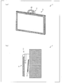
図6に、携帯テレビ3の背面図および側面図を示す。また、図7に、携帯テレビ3の一配置例を示す。図6に示すように、携帯テレビ3は、携帯テレビ3をアングル2に掛けるためのハンドル15を背面(表示面とは反対側)に有している。ハンドル15の内部には、折り曲げ可能な受電コイル8が環状になって組み込められている。具体的には、図6に示した点線のように、ハンドル15の形状に沿って組み込められている。このように、受電コイル8を携帯テレビ3のハンドル15に組み込み、ハンドル15内の空間を有効活用している。そのため、携帯テレビ3内の空間に受電コイル8を設置する空間を別途設ける必要がなく、薄型の携帯テレビ3でも何ら問題なく受電コイル8を組み込むことができる。
さらに、受電コイル8はハンドル15に組み込められているため、携帯テレビ3の本体内部にあるバックライトシャーシ等の金属部材と、受電コイル8との間に距離を置くことができる。結果、受電コイル8に起因した金属部材の発熱を最小限に抑えることが可能となる。
また、ハンドル15の構造のみを任意に設計できるようにしておくことによって、携帯テレビ3本体のサイズおよび形状に左右されずに、ハンドル15を所望の構造に設計することができる。すなわち、必要な伝送電力に応じた受電コイル8を組み込む場合でも、組み込む受電コイル8に応じて、ハンドル15を設計することができる。
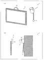
このハンドル15は、携帯テレビ3を持ち運ぶ際、およびアングル2に掛ける際には、図7中の(a)に示すように、ハンドル15が携帯テレビ3の上端部よりも上に出ている。この場合、携帯テレビ3をどこかに置いて視聴する際に、携帯テレビ3を視聴している視聴者側からハンドル15が見えてしまい、視聴の邪魔になる可能性がある。ここで、受電コイル8は、折り曲げ可能なコイルである。そのため、図7中の(b)に示すように、ハンドル15を折り曲げることができる。これによって、携帯テレビ3を視聴している視聴者側からはハンドル15を見えなくすることができ、視聴の邪魔にならない。
なお、折り曲げ可能な受電コイル8としては、例えば薄型のシート状のコイルが挙げられる。受電コイル8がシート状のコイルであると、携帯テレビ3のハンドル15を容易に折り曲げることができる。さらに、受電コイル8がシート状のコイルであると、受電コイル8の薄型化および軽量化が可能になる。したがって、ハンドル15をより小型化することができ、携帯テレビ3のデザイン性を高めることもできる。なお、折り曲げ可能な受電コイル8としてシート状のコイルを挙げたが、受電コイル8は必ずしもシート状のコイルに限定されないことは言うまでもない。
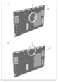
さらに図8に、携帯テレビ3の本体内部にあるバックライトシャーシ等の金属部材と、ハンドル15との位置関係を示す。本図では、両者の位置関係を分かりやすくするために、携帯テレビ3の背面を省略している。
図8中の(a)は、ハンドル15を携帯テレビ3の背面の中心に設けた場合を示している。この場合、ハンドル15全体が携帯テレビ3の本体に接しているため、ハンドル15に組み込められている受電コイル8の影響を受けて、携帯テレビ3の本体内部にあるバックライトシャーシ等の金属部材が共振し、発熱する虞がある。
一方、図8中の(b)は、ハンドル15の一部が携帯テレビ3の上端部よりも上に出た位置にハンドル15を設けた場合を示している。この場合、ハンドル15全体が携帯テレビ3の本体と接しているわけではなく、図8中の(a)の場合と比較して携帯テレビ3の本体と接している面積が小さい。そのため、ハンドル15に組み込められている受電コイル8の影響を受けて、携帯テレビ3の本体内部にあるバックライトシャーシ等の金属部材が共振して発熱する面積は小さい。結果、受電コイル8に起因した金属部材の発熱を最小限に抑えることが可能となる。
また、受電コイル8が環状(円形状)であると、給電効率が高いため好ましい。しかし、必ずしもこれに限定されるわけではなく、受電コイル8は少なくともループ状になっていて、なおかつ、送電コイル6との間で磁界結合することができるものであれば、いかなる形状であってもよい。例えば図9に、四角形のループ状になった受電コイル8を有する携帯テレビ3の背面図を示す。図9に示すように、受電コイル8は四角形のループ状になっていてもよい。あるいは、図示しないが多角形のループ状になっていてもよいし、楕円形のループ状になっていてもよい。受電コイル8は、折り曲げ可能なコイルであるため、種々の形状に対応することが可能である。
(非接触給電システム1による給電方法1)
非接触給電システム1では、上述したように、アングル2に携帯テレビ3が掛けられているか否かに応じて、アングル2は携帯テレビ3への給電を行っている。より具体的には、検知回路7による検知結果に応じて、アングル2は携帯テレビ3への給電を行っている。そこで、アングル2の検知回路7による検知方法の一例を、図10および図11を参照して説明する。図10は、アングル2を示す側面図である。また図11は、アングル2の内部構成を示す図であり、図中の(a)は携帯テレビ3がアングル2に掛けられていない状態の図であり、(b)は携帯テレビ3がアングル2に掛けられている状態の図である。なお、以下に示す検知方法はあくまでも一例であり、検知回路7による検知方法は、これに限定されるものではない。
非接触給電システム1では、上述したように、アングル2に携帯テレビ3が掛けられているか否かに応じて、アングル2は携帯テレビ3への給電を行っている。より具体的には、検知回路7による検知結果に応じて、アングル2は携帯テレビ3への給電を行っている。そこで、アングル2の検知回路7による検知方法の一例を、図10および図11を参照して説明する。図10は、アングル2を示す側面図である。また図11は、アングル2の内部構成を示す図であり、図中の(a)は携帯テレビ3がアングル2に掛けられていない状態の図であり、(b)は携帯テレビ3がアングル2に掛けられている状態の図である。なお、以下に示す検知方法はあくまでも一例であり、検知回路7による検知方法は、これに限定されるものではない。
図10に示すように、アングル2において、携帯テレビ3のハンドル15が掛けられる所にスイッチ14が取り付けられている。具体的には、図11中の(a)に示すように、アングル2内部には、検知電極17と接地電極19とからなる1対の電極が間隔を空けて設けられている。検知電極17は、検知回路7に接続されており、スイッチ14に接している。一方、接地電極19は接地されている。検知電極17には図示しない電源が微弱電流を流している。
携帯テレビ3がアングル2に掛けられると、ハンドル15がスイッチ14を押し下げるため、図11中の(b)に示すように、スイッチ14はアングル2の内部に押し込められる。その結果、スイッチ14が検知電極17を押し下げて、検知電極17は接地電極19に接触する。これによって、検知電極17と接地電極19とが導通して、両電極間に電流が流れる。検知回路7は、電流が流れたことを検知して、アングル2に携帯テレビ3が掛けられていると判定する。逆に、図11中の(a)に示したように、アングル2に携帯テレビ3が掛けられていない時には、検知電極17と接地電極19とが導通していないため、両電極間には電流が流れない。そのため、検知回路7は、電流を検知せず、アングル2に携帯テレビ3が掛けられていないとを判定する。
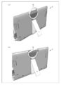
図12および図13を参照して、検知回路7がアングル2に携帯テレビ3が掛けられているか否かを検知してから、その検知結果に応じて携帯テレビ3に給電が行われるまでの具体的なフローについて、図14に沿って説明する。図12中の(a)および(b)は、携帯テレビ3がアングル2に掛けられていない状態を示す図であり、図13中の(a)および(b)は、携帯テレビ3がアングル2に掛けられている状態を示す図である。また、図14は、非接触給電システム1による給電方法を示すフロー図である。
まずアングル2の検知回路7は、携帯テレビ3がアングル2に掛けられているか否かを検出する。具体的には、検知回路7は、ハンドル15がアングル2に掛けられているか否かを検出する(ステップ1;以下S1と略記する)。図12中の(a)に示すように、視聴者が携帯テレビ3を持ち運んでどこかに置いて視聴している場合等では、携帯テレビ3はアングル2に掛けられていない。そのため、図12中の(b)に示すように、携帯テレビ3のハンドル15はアングル2に取り付けられたスイッチ14を押下せず、検知電極17および接地電極19の間には電流が流れない。結果、検知回路7は、アングル2に携帯テレビ3が掛けられていないと判定する(S2,NO)。
検知回路7が検知した情報は非接触給電IF回路5に送られる。そして、非接触給電IF回路5では、検知回路7からの情報に基づいて、送電コイル6への電力の供給は行わない。すなわち、携帯テレビ3への非接触給電は行われない(S4)。
一方、図13中の(a)に示すように、視聴者が携帯テレビ3を壁に掛けた状態で視聴する場合、あるいは携帯テレビ3を視聴していない場合等では、携帯テレビ3はアングル2に掛けられている。そのため、図13中の(b)に示すように、携帯テレビ3のハンドル15はアングル2に取り付けられたスイッチ14を押下しており、検知電極17および接地電極19の間には電流が流れる。結果、検知回路7は、アングル2に携帯テレビ3が掛けられていると判定する(S2,YES)。
検知回路7が検知した情報は非接触給電IF回路5に送られ、非接触給電IF回路5では、検知回路7からの情報に基づいて、送電コイル6への電力の供給を行う。すなわち、携帯テレビ3への非接触給電が行われる(S3)。
その後は、再びS1に戻り、検知回路7はアングル2にハンドル15が掛けられているか否かの検知を行い、S2以降の処理を繰り返し行う。以上の処理を繰り返し行うことによって、携帯テレビ3がどこかに置かれていたところ(図12の状態)、アングル2に掛けられた(図13の状態)場合は、アングル2は携帯テレビ3への非接触給電を開始する。一方、携帯テレビ3がアングルに掛けられていたところ(図13の状態)、アングル2から外された(図12の状態)場合は、アングル2は携帯テレビ3への非接触給電を停止する。したがって、アングル2は、自身にハンドル15が掛けられていることを検知回路7が検知している間は非接触給電を行い、自身にハンドル15が掛けられていないと検知回路7が検知すれば非接触給電を取り止める。
なお、以上では検知回路7は、アングル2にハンドル15が掛けられていないと判定した場合も非接触給電IF回路5にその情報を送っているが、アングル2にハンドル15が掛けられていると判定した場合のみにその情報を非接触給電IF回路5に送ってもよく、特に限定はない。この場合は、非接触給電IF回路5は、検知回路7から検知情報が送られてきた場合のみ送電コイル6への電力供給を行えばよい。
(非接触給電システム1による給電方法2)
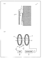
アングル2に携帯テレビ3が掛けられているか否かを検知する方法は、必ずしもスイッチ14を利用した検知方法に限定されるわけでない。そこで、以下ではアングル2に携帯テレビ3が掛けられているか否かを、スイッチ14を用いずに検知する方法の一例を、図15および図16を参照して説明する。図15中の(a)は、携帯テレビ3がアングル2に掛けられていない状態を示す図であり、(b)は、携帯テレビ3がアングル2に掛けられていないときの送電コイル6および受電コイル8の状態を示す図である。また、図16中の(a)は、携帯テレビ3がアングル2に掛けられている状態を示す図であり、(b)は、携帯テレビ3がアングル2に掛けられているときの送電コイル6および受電コイル8の状態を示す図である。
アングル2に携帯テレビ3が掛けられているか否かを検知する方法は、必ずしもスイッチ14を利用した検知方法に限定されるわけでない。そこで、以下ではアングル2に携帯テレビ3が掛けられているか否かを、スイッチ14を用いずに検知する方法の一例を、図15および図16を参照して説明する。図15中の(a)は、携帯テレビ3がアングル2に掛けられていない状態を示す図であり、(b)は、携帯テレビ3がアングル2に掛けられていないときの送電コイル6および受電コイル8の状態を示す図である。また、図16中の(a)は、携帯テレビ3がアングル2に掛けられている状態を示す図であり、(b)は、携帯テレビ3がアングル2に掛けられているときの送電コイル6および受電コイル8の状態を示す図である。
図15中の(a)に示すように、アングル2のプラグ11はコンセント等の外部電源に接続されており、外部電源から電力を得ている。具体的には、アングル2のプラグ11が外部電源に接続されると、図15中の(b)に示すように、送電コイルに励磁電流i1が流れ、送電コイルには磁束φ1が発生する。なお、この際の励磁電流i1は微弱な電流でよく、アングル2に携帯テレビ3を掛けた際にハンドル15内の受電コイル8を起電する磁束を励磁でき得る電流であればよい。ここで、ハンドル15内の受電コイル8には磁束が通っていないので、電圧v2は発生せず、電流は流れていない状態である(電流i2はほぼ0アンペア)。この場合、電流検出回路21が送電コイル6に流れる電流が所定値未満の電流であると検出し、アングル2に携帯テレビ3が掛けられていないと判定する。なお、上記の所定値は、電流i1よりも大きい電流値である。
一方、図16中の(a)に示すように、携帯テレビ3がアングル2に掛けられると、図16中の(b)に示すように、ハンドル15内の受電コイル8の中を、送電コイル6により励起した磁束φ1が通り、受電コイルに電圧v2が発生する。この電圧v2により、受電コイル8に接続されたテレビ内充電回路等の負荷20に電流i2が流れる。電流i2が流れることにより、受電コイル8には逆方向の磁束φ2が発生する。この磁束φ2を打ち消すように送電コイル6に磁束φ3が発生するため、結果、磁束φ3を発生させるための電流i3が電流i1にプラスされる。それ故、結果として送電コイル6に流れる電流は、受電コイル8に流れる負荷電流の影響を受けて電流i1から電流(i1+i3)に増加する。送電コイル6に流れる電流の増加、すなわち送電コイル6に流れる電流が所定値以上になったことを電流検出回路21が検出すると、アングル2に携帯テレビ3が掛けられていると判定する。
逆に、図15中の(a)に示したように、アングル2から携帯テレビ3が外されると、逆方向の磁束φ2がなくなるため、その磁束φ2を打ち消すために発生していたφ3の磁束も消滅する。その結果、電流i3もなくなるため、送電コイル6に流れる電流は電流i3の分だけ減少する。送電コイル6に流れる電流の減少、すなわち送電コイル6に流れる電流が所定値未満になったことを電流検出回路21が検出すると、アングル2に携帯テレビ3が掛けられていないと判定する。
再び図15および図16を参照して、電流検出回路21がアングル2に携帯テレビ3が掛けられているか否かを検知してから、その検知結果に応じて携帯テレビ3に給電が行われるまでの具体的なフローについて、図17に沿って説明する。図17は、非接触給電システム1による給電方法を示すフロー図である。
まずアングル2の電流検出回路21は、携帯テレビ3がアングル2に掛けられているか否かを検出する。具体的には、電流検出回路21は、送電コイル6に流れる電流が増加したか否かを検出する(ステップ11;以下S11と略記する)。図16中の(a)に示したように、視聴者が携帯テレビ3を壁に掛けた状態で視聴する場合、あるいは携帯テレビ3を視聴していない場合等では、携帯テレビ3はアングル2に掛けられている。そのため、図16中の(b)に示したように、送電コイル6に流れる電流は、受電コイル8に流れる負荷電流の影響を受けているので、送電コイル6に流れる電流は所定値以上になる。送電コイル6に流れる電流が所定値以上であることを電流検出回路21が検出すると、アングル2に携帯テレビ3が掛けられていると判定する(S12,YES)。
電流検出回路21が検知した情報は、非接触給電IF回路5に送られる。そして、非接触給電IF回路5では、電流検出回路21からの情報に基づいて、送電コイル6の電流を増加することで受電コイル8への送電量を増やす。すなわち、携帯テレビ3への非接触給電が行われる(S13)。
一方、図15中の(a)に示したように、視聴者が携帯テレビ3を持ち運んでどこかに置いて視聴している場合等では、携帯テレビ3はアングル2に掛けられていない。そのため、図15中の(b)に示したように、送電コイル6に流れる電流は、受電コイル8に流れる負荷電流の影響を受けていないので、送電コイル6に流れる電流は所定値未満になる。送電コイル6に流れる電流が所定値未満であることを電流検出回路21が検出すると、アングル2に携帯テレビ3が掛けられていないと判定する。
電流検出回路21が検知した情報は非接触給電IF回路5に送られる。そして、非接触給電IF回路5では、電流検出回路21からの情報に基づいて、送電コイル6の電流を微弱な電流にして受電コイル8への送電を行わない。すなわち、携帯テレビ3への非接触給電は行われない(S14)。
その後は、再びS11に戻り、電流検出回路21はアングル2にハンドル15が掛けられているか否かの検知を行い、S12以降の処理を繰り返し行う。以上の処理を繰り返し行うことによって、携帯テレビ3がどこかに置かれていたところ(図15中の(a)の状態)、アングル2に掛けられた(図16中の(a)の状態)場合は、アングル2は携帯テレビ3への非接触給電を開始する。一方、携帯テレビ3がアングルに掛けられていたところ(図16中の(a)の状態)、アングル2から外された(図15中の(a)の状態)場合は、アングル2は携帯テレビ3への非接触給電を停止する。したがって、アングル2は、自身にハンドル15が掛けられていることを電流検出回路21が検知している間は非接触給電を行い、自身にハンドル15が掛けられていないと電流検出回路21が検知すれば非接触給電を取り止める。
なお、以上では電流検出回路21は、アングル2にハンドル15が掛けられていないと判定した場合も非接触給電IF回路5にその情報を送っているが、アングル2にハンドル15が掛けられていると判定した場合のみにその情報を非接触給電IF回路5に送ってもよく、特に限定はない。この場合は、非接触給電IF回路5は、電流検出回路21から検知情報が送られてきた場合のみ送電コイル6への電力供給を行えばよい。
また、冒頭で述べたように、本発明の一実施形態に係る非接触給電システム1では、ハンドルを備えた持ち運び可能な表示装置に、給電装置から非接触給電を行う。以上では、本発明の一実施形態に係る非接触給電システム1について、表示装置が携帯テレビ3であり、給電装置が携帯テレビ3を壁に掛けるためのアングル2である場合を例に挙げて説明したが、これはあくまでも一例であり、本発明の一実施形態に係る非接触給電システム1はこれに限定されるわけではない。加えて、本発明の一実施形態に係る非接触給電システム1において非接触給電が行われるのは、表示装置(携帯テレビ3)を給電装置(アングル2)に掛けた場合に限定されるものではない。
したがって、本発明は、上述した実施形態に限定されるものではなく、請求項に示した範囲で種々の変更が可能である。すなわち、請求項に示した範囲で適宜変更した技術的手段を組み合わせて得られる実施形態についても本発明の技術的範囲に含まれる。
〔実施形態の総括〕
以上のように、本発明に係る表示装置は、上記の課題を解決するために、ハンドルを備えた持ち運び可能な表示装置であって、上記ハンドルの内部に、非接触給電用の受電コイルが組み込められていることを特徴としている。
以上のように、本発明に係る表示装置は、上記の課題を解決するために、ハンドルを備えた持ち運び可能な表示装置であって、上記ハンドルの内部に、非接触給電用の受電コイルが組み込められていることを特徴としている。
上記の構成によれば、受電コイルは表示装置のハンドルの内部に組み込められている。このように、受電コイルを表示装置のハンドルに組み込み、ハンドル内の空間を有効活用している。そのため、表示装置内の空間に受電コイルを設置する空間を別途設ける必要がなく、薄型の表示装置でも何ら問題なく受電コイルを組み込むことができる。
また、ハンドルの構造のみを任意に設計できるようにしておくことによって、表示装置本体のサイズおよび形状に左右されずに、ハンドルを所望の構造に設計することができる。すなわち、必要な伝送電力に応じた受電コイルを組み込む場合でも、組み込む受電コイルに応じて、ハンドルを設計することができる。
さらに、受電コイルは表示装置のハンドルに組み込められているため、表示装置の本体内部にあるバックライトシャーシ等の金属部材と、受電コイルとの間に距離を置くことができる。結果、受電コイルに起因した金属部材の発熱を最小限に抑えることが可能となる。
また、本発明に係る表示装置においては、上記受電コイルは、ループ状であることを特徴としている。
また、本発明に係る表示装置においては、上記受電コイルは、円形、楕円形、あるいは多角形のループ状であることを特徴としている。
上記の構成によれば、高い給電効率が得られる。
また、本発明に係る表示装置においては、上記受電コイルは、折り曲げ可能なコイルであることを特徴としている。
上記の構成によれば、受電コイルが折り曲げ可能なコイルであるため、何ら問題なく表示装置のハンドルに受電コイルを組み込めることができる。
また、本発明に係る表示装置においては、上記受電コイルは、シート状のコイルであることを特徴としている。
上記の構成によれば、受電コイルはシート状のコイルであるため、ハンドルを容易に折り曲げることができる。さらに、受電コイルがシート状のコイルであると、受電コイルの薄型化および軽量化が可能になる。したがって、ハンドルをより小型化することができ、表示装置のデザイン性を高めることもできる。
また、本発明に係る表示装置においては、上記ハンドルは、その一部が上記表示装置の上端部よりも上に出た位置に設けられていることを特徴としている。
上記の構成によれば、表示装置のハンドルが表示装置の上端部よりも上に出ていると、ハンドルの一部が表示装置の本体と接している面積が小さい。そのため、ハンドルに組み込められている受電コイルの影響を受けて、表示装置の本体内部にあるバックライトシャーシ等の金属部材が共振して発熱する面積は小さい。結果、受電コイルに起因した金属部材の発熱を最小限に抑えることが可能となる。
さらに、受電コイルを折り曲げ可能なコイルにすることにより、ハンドルを折り曲げることが可能である。これによって、表示装置を視聴している視聴者側からはハンドルを見えなくすることができ、視聴の邪魔にならない。
本発明に係る非接触給電システムは、上記の課題を解決するために、上述したいずれかの表示装置と、外部から電力が供給される電源部と、上記電源部からの電力が供給される非接触給電用の送電コイルとを備えた給電装置とを備え、上記ハンドルが、上記給電装置に近接した所定の位置にある場合に、上記送電コイルと上記受電コイルとが磁気的に結合することによって、上記電力を上記表示装置に非接触給電することを特徴としている。
上記の構成によれば、送電コイルと受電コイルとの間の電磁誘導を利用して、表示装置に対して非接触で給電することができる。特に受電コイルは表示装置のハンドルの内部に埋め込められているため、非接触給電のための新たな部材を別途設ける必要がなく、薄型の表示装置でも何ら問題なく非接触給電を行うことができる。
また、本発明に係る非接触給電システムにおいては、上記給電装置は、上記ハンドルが上記所定の位置にあるか否かを検知する検知部をさらに備え、上記電源部は、上記検知部が、上記ハンドルが上記所定の位置にあることを検知すると、上記電力を上記送電コイルに供給し、上記検知部が、上記ハンドルが上記所定の位置にないことを検知すると、上記電力を上記送電コイルに供給しないことを特徴としている。
上記の構成によれば、給電装置は、ハンドルが所定の位置にあることを検知部が検知している間は非接触給電を行い、ハンドルが所定の位置にないことを検知部が検知すれば非接触給電を取り止める。したがって、ハンドルが所定の位置にある間だけ、表示装置に非接触給電を行うことができる。
また、本発明に係る非接触給電システムにおいては、上記給電装置は、壁に取り付けられているアングルであり、上記ハンドルは、上記アングルに掛けることができ、上記所定の位置は、上記ハンドルが上記アングルに掛けられている状態のことであることを特徴としている。
上記の構成によれば、表示装置を壁に掛けることができる。また、アングルは、自身にハンドルが掛けられていることを検知部が検知している間は非接触給電を行い、自身にハンドルが掛けられていないと検知部が検知すれば非接触給電を取り止める。したがって、アングルに表示装置が掛けられている間だけ、表示装置に非接触給電を行うことができる。
また、本発明に係る非接触給電システムにおいては、上記給電装置は、壁に取り付けられているアングルであり、上記ハンドルは、上記アングルに掛けることができ、上記所定の位置は、上記ハンドルが上記アングルに掛けられている状態のことであり、上記アングルにはスイッチが設けられており、上記検知部は、上記ハンドルが上記アングルに設けられた上記スイッチを押下していると、上記ハンドルが上記アングルに掛けられている状態にあると検知し、上記ハンドルが上記アングルに設けられた上記スイッチを押下していないと、上記ハンドルが上記アングルに掛けられていない状態にあると検知することを特徴としている。
上記の構成によれば、給電装置は、ハンドルがアングルに掛けられている状態にあることを検知部が検知している間は非接触給電を行い、ハンドルがアングルに掛けられていない状態にあることを検知部が検知すれば非接触給電を取り止める。したがって、ハンドルがアングルに掛けられている状態にある間だけ、表示装置に非接触給電を行うことができる。
また、本発明に係る非接触給電システムにおいては、上記送電コイルには、微弱電流が流されており、上記検知部は、上記送電コイルに流れる電流の大きさが、上記微弱電流よりも大きい所定値以上の電流であるか否かを検出する電流検出回路を備えており、上記電流検出回路が、上記送電コイルに流れる電流が上記所定値以上の電流であると検出すると、上記ハンドルが上記所定の位置にあると検知し、上記電流検出回路が、上記送電コイルに流れる電流が上記所定値未満の電流であると検出すると、上記ハンドルが上記所定の位置にあると検知することを特徴としている。
上記の構成によれば、検知部はスイッチ等の手段を用いずに、ハンドルが所定の位置にあるか否かを検知することができる。
また、本発明に係るテレビジョン受像機は、上記の課題を解決するために、上述したいずれかの表示装置を備えていることを特徴としている。
上記の構成よれば、内部に受電コイルを設置するための空間を十分に確保することができ、なおかつ、内部の金属製の部材が受電コイルの影響を受けて発熱しない持ち運び可能なテレビジョン受像機が得られる。
発明の詳細な説明の項においてなされた具体的な実施形態または実施例は、あくまでも、本発明の技術内容を明らかにするものであって、そのような具体例にのみ限定して狭義に解釈されるべきものではなく、本発明の精神と次に記載する請求の範囲内で、いろいろと変更して実施することができるものである。
本発明に係る非接触給電システムは、持ち運び可能なテレビジョン受像機および当該テレビジョン受像機を壁に掛けるために設置されるアングルに適用可能である。
1 非接触給電システム
2 アングル
3 テレビジョン受像機(携帯テレビ)
4 電源基板
5 非接触給電IF回路
6 送電コイル
7 検知回路
8 受電コイル
9 非接触給電IF回路
10 バッテリ
11 プラグ
12 給電装置
13 携帯電話機
14 スイッチ
15 ハンドル
16 送電コイル
17 検知電極
18 受電コイル
19 接地電極
20 負荷
21 電流検出回路
2 アングル
3 テレビジョン受像機(携帯テレビ)
4 電源基板
5 非接触給電IF回路
6 送電コイル
7 検知回路
8 受電コイル
9 非接触給電IF回路
10 バッテリ
11 プラグ
12 給電装置
13 携帯電話機
14 スイッチ
15 ハンドル
16 送電コイル
17 検知電極
18 受電コイル
19 接地電極
20 負荷
21 電流検出回路
Claims (12)
- ハンドルを備えた持ち運び可能な表示装置であって、上記ハンドルの内部に、非接触給電用の受電コイルが組み込められていることを特徴とする表示装置。
- 上記受電コイルは、ループ状であることを特徴とする請求項1に記載の表示装置。
- 上記受電コイルは、円形、楕円形、あるいは多角形のループ状であることを特徴とする請求項2に記載の表示装置。
- 上記受電コイルは、折り曲げ可能なコイルであることを特徴とする請求項1~3のいずれか1項に記載の表示装置。
- 上記受電コイルは、シート状のコイルであることを特徴とする請求項4に記載の表示装置。
- 上記ハンドルは、その一部が上記表示装置の上端部よりも上に出た位置に設けられていることを特徴とする請求項1~5のいずれか1項に記載の表示装置。
- 請求項1~6のいずれか1項に記載の表示装置と、
外部から電力が供給される電源部と、上記電源部からの電力が供給される非接触給電用の送電コイルとを備えた給電装置とを備え、
上記ハンドルが、上記給電装置に近接した所定の位置にある場合に、上記送電コイルと上記受電コイルとが磁気的に結合することによって、上記電力を上記表示装置に非接触給電することを特徴とする非接触給電システム。 - 上記給電装置は、上記ハンドルが上記所定の位置にあるか否かを検知する検知部をさらに備え、
上記電源部は、
上記検知部が、上記ハンドルが上記所定の位置にあることを検知すると、上記電力を上記送電コイルに供給し、
上記検知部が、上記ハンドルが上記所定の位置にないことを検知すると、上記電力を上記送電コイルに供給しないことを特徴とする請求項7に記載の非接触給電システム。 - 上記給電装置は、壁に取り付けられているアングルであり、
上記ハンドルは、上記アングルに掛けることができ、
上記所定の位置は、上記ハンドルが上記アングルに掛けられている状態のことであることを特徴とする請求項7または8に記載の非接触給電システム。 - 上記給電装置は、壁に取り付けられているアングルであり、
上記ハンドルは、上記アングルに掛けることができ、
上記所定の位置は、上記ハンドルが上記アングルに掛けられている状態のことであり、
上記アングルにはスイッチが設けられており、
上記検知部は、
上記ハンドルが上記アングルに設けられた上記スイッチを押下していると、上記ハンドルが上記アングルに掛けられている状態にあると検知し、
上記ハンドルが上記アングルに設けられた上記スイッチを押下していないと、上記ハンドルが上記アングルに掛けられていない状態にあると検知することを特徴とする請求項8に記載の非接触給電システム。 - 上記送電コイルには、微弱電流が流されており、
上記検知部は、
上記送電コイルに流れる電流の大きさが、上記微弱電流よりも大きい所定値以上の電流であるか否かを検出する電流検出回路を備えており、
上記電流検出回路が、上記送電コイルに流れる電流が上記所定値以上の電流であると検出すると、上記ハンドルが上記所定の位置にあると検知し、
上記電流検出回路が、上記送電コイルに流れる電流が上記所定値未満の電流であると検出すると、上記ハンドルが上記所定の位置にあると検知することを特徴とする請求項8に記載の非接触給電システム。 - 請求項1~6のいずれか1項に記載の表示装置を備えていることを特徴とするテレビジョン受像機。
Priority Applications (2)
| Application Number | Priority Date | Filing Date | Title |
|---|---|---|---|
| CN201280071851.4A CN104247204A (zh) | 2012-03-27 | 2012-09-14 | 显示装置、及具备该显示装置的非接触供电系统、以及具备该显示装置的电视接收机 |
| US14/388,112 US20150049252A1 (en) | 2012-03-27 | 2012-09-14 | Display device, contactless power supply system equipped with display device, and television receiver equipped with display device |
Applications Claiming Priority (4)
| Application Number | Priority Date | Filing Date | Title |
|---|---|---|---|
| JP2012-072200 | 2012-03-27 | ||
| JP2012072200 | 2012-03-27 | ||
| JP2012185858A JP5315445B1 (ja) | 2012-03-27 | 2012-08-24 | 表示装置、および当該表示装置を備えた非接触給電システム、ならびに当該表示装置を備えたテレビジョン受像機 |
| JP2012-185858 | 2012-08-24 |
Publications (1)
| Publication Number | Publication Date |
|---|---|
| WO2013145376A1 true WO2013145376A1 (ja) | 2013-10-03 |
Family
ID=49258720
Family Applications (1)
| Application Number | Title | Priority Date | Filing Date |
|---|---|---|---|
| PCT/JP2012/073725 Ceased WO2013145376A1 (ja) | 2012-03-27 | 2012-09-14 | 表示装置、および当該表示装置を備えた非接触給電システム、ならびに当該表示装置を備えたテレビジョン受像機 |
Country Status (4)
| Country | Link |
|---|---|
| US (1) | US20150049252A1 (ja) |
| JP (1) | JP5315445B1 (ja) |
| CN (1) | CN104247204A (ja) |
| WO (1) | WO2013145376A1 (ja) |
Families Citing this family (4)
| Publication number | Priority date | Publication date | Assignee | Title |
|---|---|---|---|---|
| US10003218B2 (en) * | 2014-12-20 | 2018-06-19 | Intel Corporation | Chassis design for wireless-charging coil integration for computing systems |
| US20160179140A1 (en) * | 2014-12-20 | 2016-06-23 | Intel Corporation | Chassis Design for Wireless-Charging Coil Integration for Computing Systems |
| US20190296574A1 (en) * | 2016-06-30 | 2019-09-26 | Intel Corporation | Computing system with external wireless charging coil |
| KR20210073296A (ko) * | 2019-12-10 | 2021-06-18 | 삼성전자주식회사 | 공중부양 디스플레이 장치 |
Citations (6)
| Publication number | Priority date | Publication date | Assignee | Title |
|---|---|---|---|---|
| JPH04185236A (ja) * | 1990-11-19 | 1992-07-02 | Aloka Co Ltd | 無線式放射線検出装置 |
| JPH0731064A (ja) * | 1993-07-06 | 1995-01-31 | Tdk Corp | 非接触形充電器 |
| JPH11146569A (ja) * | 1997-11-07 | 1999-05-28 | Staff Kk | 非接触電力伝送システム |
| JP2005303390A (ja) * | 2004-04-06 | 2005-10-27 | Fuji Photo Film Co Ltd | 携帯型電子機器支援システム |
| JP2010016977A (ja) * | 2008-07-03 | 2010-01-21 | Fujifilm Corp | 充電システム及び給電装置 |
| JP2011030419A (ja) * | 2007-10-09 | 2011-02-10 | Powermat Ltd | 電気装置の誘導受電装置 |
Family Cites Families (7)
| Publication number | Priority date | Publication date | Assignee | Title |
|---|---|---|---|---|
| JP4185236B2 (ja) * | 2000-06-19 | 2008-11-26 | イーストマン コダック カンパニー | 固体撮像素子および撮像装置 |
| US7263388B2 (en) * | 2001-06-29 | 2007-08-28 | Nokia Corporation | Charging system for portable equipment |
| JP4318044B2 (ja) * | 2005-03-03 | 2009-08-19 | ソニー株式会社 | 電力供給システム、電力供給装置および方法、受電装置および方法、記録媒体、並びにプログラム |
| US7193698B2 (en) * | 2005-07-18 | 2007-03-20 | Powerchip Semiconductor Corp. | Wafer defect detection methods and systems |
| US7495414B2 (en) * | 2005-07-25 | 2009-02-24 | Convenient Power Limited | Rechargeable battery circuit and structure for compatibility with a planar inductive charging platform |
| US8193769B2 (en) * | 2007-10-18 | 2012-06-05 | Powermat Technologies, Ltd | Inductively chargeable audio devices |
| WO2012081749A1 (ko) * | 2010-12-16 | 2012-06-21 | 엘지전자 주식회사 | 무선전력 공급 장치, 무선전력 수신이 가능한 전자 기기 및 무선전력 전송 제어 방법 |
-
2012
- 2012-08-24 JP JP2012185858A patent/JP5315445B1/ja not_active Expired - Fee Related
- 2012-09-14 US US14/388,112 patent/US20150049252A1/en not_active Abandoned
- 2012-09-14 WO PCT/JP2012/073725 patent/WO2013145376A1/ja not_active Ceased
- 2012-09-14 CN CN201280071851.4A patent/CN104247204A/zh active Pending
Patent Citations (6)
| Publication number | Priority date | Publication date | Assignee | Title |
|---|---|---|---|---|
| JPH04185236A (ja) * | 1990-11-19 | 1992-07-02 | Aloka Co Ltd | 無線式放射線検出装置 |
| JPH0731064A (ja) * | 1993-07-06 | 1995-01-31 | Tdk Corp | 非接触形充電器 |
| JPH11146569A (ja) * | 1997-11-07 | 1999-05-28 | Staff Kk | 非接触電力伝送システム |
| JP2005303390A (ja) * | 2004-04-06 | 2005-10-27 | Fuji Photo Film Co Ltd | 携帯型電子機器支援システム |
| JP2011030419A (ja) * | 2007-10-09 | 2011-02-10 | Powermat Ltd | 電気装置の誘導受電装置 |
| JP2010016977A (ja) * | 2008-07-03 | 2010-01-21 | Fujifilm Corp | 充電システム及び給電装置 |
Also Published As
| Publication number | Publication date |
|---|---|
| US20150049252A1 (en) | 2015-02-19 |
| JP5315445B1 (ja) | 2013-10-16 |
| JP2013230072A (ja) | 2013-11-07 |
| CN104247204A (zh) | 2014-12-24 |
Similar Documents
| Publication | Publication Date | Title |
|---|---|---|
| US20230178817A1 (en) | Feed unit, feed system, and electronic device for increasing power supplied to a battery based on a device state and/or a control of a charging current | |
| JP6070789B2 (ja) | 給電装置および給電システム | |
| US9356476B2 (en) | Electronic device and power supplying method and wireless power supplying system thereof | |
| US10938238B2 (en) | Electronic apparatus and feed system | |
| US9680328B2 (en) | Electronic apparatus and feed system | |
| US9847813B2 (en) | Feed unit and feed system for non-contact power transmission | |
| US20140339912A1 (en) | Feed unit and feed system | |
| JP5857861B2 (ja) | 給電装置、給電システムおよび電子機器 | |
| JP5315445B1 (ja) | 表示装置、および当該表示装置を備えた非接触給電システム、ならびに当該表示装置を備えたテレビジョン受像機 | |
| CN103947074B (zh) | 电子设备、馈电装置和馈电系统 | |
| US20180212447A1 (en) | Electronic apparatus, electronic apparatus system, and method of operating electronic apparatus | |
| JP5975043B2 (ja) | 電子機器および給電システム | |
| CN103959594B (zh) | 电子设备和馈电系统 | |
| WO2011160409A1 (zh) | 无线供电检测控制方法与系统 | |
| JP5596828B2 (ja) | 表示装置、および当該表示装置を備えた非接触給電システム、ならびに当該表示装置を備えたテレビジョン受像機 |
Legal Events
| Date | Code | Title | Description |
|---|---|---|---|
| 121 | Ep: the epo has been informed by wipo that ep was designated in this application |
Ref document number: 12872581 Country of ref document: EP Kind code of ref document: A1 |
|
| WWE | Wipo information: entry into national phase |
Ref document number: 14388112 Country of ref document: US |
|
| NENP | Non-entry into the national phase |
Ref country code: DE |
|
| 122 | Ep: pct application non-entry in european phase |
Ref document number: 12872581 Country of ref document: EP Kind code of ref document: A1 |