WO2013143243A1 - 一种调变费托合成产物分布的超重力旋转填充床催化反应器及应用 - Google Patents
一种调变费托合成产物分布的超重力旋转填充床催化反应器及应用 Download PDFInfo
- Publication number
- WO2013143243A1 WO2013143243A1 PCT/CN2012/079015 CN2012079015W WO2013143243A1 WO 2013143243 A1 WO2013143243 A1 WO 2013143243A1 CN 2012079015 W CN2012079015 W CN 2012079015W WO 2013143243 A1 WO2013143243 A1 WO 2013143243A1
- Authority
- WO
- WIPO (PCT)
- Prior art keywords
- heat exchange
- rotor
- catalyst
- reactor
- reaction
- Prior art date
- Legal status (The legal status is an assumption and is not a legal conclusion. Google has not performed a legal analysis and makes no representation as to the accuracy of the status listed.)
- Ceased
Links
Classifications
-
- B—PERFORMING OPERATIONS; TRANSPORTING
- B01—PHYSICAL OR CHEMICAL PROCESSES OR APPARATUS IN GENERAL
- B01J—CHEMICAL OR PHYSICAL PROCESSES, e.g. CATALYSIS OR COLLOID CHEMISTRY; THEIR RELEVANT APPARATUS
- B01J8/00—Chemical or physical processes in general, conducted in the presence of fluids and solid particles; Apparatus for such processes
- B01J8/08—Chemical or physical processes in general, conducted in the presence of fluids and solid particles; Apparatus for such processes with moving particles
- B01J8/10—Chemical or physical processes in general, conducted in the presence of fluids and solid particles; Apparatus for such processes with moving particles moved by stirrers or by rotary drums or rotary receptacles or endless belts
-
- B—PERFORMING OPERATIONS; TRANSPORTING
- B01—PHYSICAL OR CHEMICAL PROCESSES OR APPARATUS IN GENERAL
- B01J—CHEMICAL OR PHYSICAL PROCESSES, e.g. CATALYSIS OR COLLOID CHEMISTRY; THEIR RELEVANT APPARATUS
- B01J19/00—Chemical, physical or physico-chemical processes in general; Their relevant apparatus
- B01J19/24—Stationary reactors without moving elements inside
- B01J19/2405—Stationary reactors without moving elements inside provoking a turbulent flow of the reactants, such as in cyclones, or having a high Reynolds-number
-
- B—PERFORMING OPERATIONS; TRANSPORTING
- B01—PHYSICAL OR CHEMICAL PROCESSES OR APPARATUS IN GENERAL
- B01J—CHEMICAL OR PHYSICAL PROCESSES, e.g. CATALYSIS OR COLLOID CHEMISTRY; THEIR RELEVANT APPARATUS
- B01J8/00—Chemical or physical processes in general, conducted in the presence of fluids and solid particles; Apparatus for such processes
- B01J8/02—Chemical or physical processes in general, conducted in the presence of fluids and solid particles; Apparatus for such processes with stationary particles, e.g. in fixed beds
- B01J8/0207—Chemical or physical processes in general, conducted in the presence of fluids and solid particles; Apparatus for such processes with stationary particles, e.g. in fixed beds the fluid flow within the bed being predominantly horizontal
- B01J8/0214—Chemical or physical processes in general, conducted in the presence of fluids and solid particles; Apparatus for such processes with stationary particles, e.g. in fixed beds the fluid flow within the bed being predominantly horizontal in a cylindrical annular shaped bed
-
- C—CHEMISTRY; METALLURGY
- C10—PETROLEUM, GAS OR COKE INDUSTRIES; TECHNICAL GASES CONTAINING CARBON MONOXIDE; FUELS; LUBRICANTS; PEAT
- C10G—CRACKING HYDROCARBON OILS; PRODUCTION OF LIQUID HYDROCARBON MIXTURES, e.g. BY DESTRUCTIVE HYDROGENATION, OLIGOMERISATION, POLYMERISATION; RECOVERY OF HYDROCARBON OILS FROM OIL-SHALE, OIL-SAND, OR GASES; REFINING MIXTURES MAINLY CONSISTING OF HYDROCARBONS; REFORMING OF NAPHTHA; MINERAL WAXES
- C10G2/00—Production of liquid hydrocarbon mixtures of undefined composition from oxides of carbon
- C10G2/30—Production of liquid hydrocarbon mixtures of undefined composition from oxides of carbon from carbon monoxide with hydrogen
- C10G2/32—Production of liquid hydrocarbon mixtures of undefined composition from oxides of carbon from carbon monoxide with hydrogen with the use of catalysts
- C10G2/34—Apparatus, reactors
Definitions
- the present invention relates to a reactor for modulating the distribution of Fischer-Tropsch synthesis products, and more particularly to a rotary packed bed catalytic reactor having a multi-layered rotor and a heat exchange section composed of concentric annular catalyst layers, belonging to a supergravity reaction Technology field.
- Syngas (co, co 2 and 3 ⁇ 4 mixed gas) is produced from various hydrocarbon-containing raw materials such as natural gas, asphalt, coal, biomass, etc., and the synthesis gas is used to produce liquid hydrocarbons by Fischer-Tropsch synthesis.
- Very good oil replacement technology The Fischer Tropsch process, also known as FT synthesis, is a process for synthesizing paraffin-based liquid fuels using a synthesis gas as a raw material under a suitable catalyst.
- the Fischer-Tropsch synthesis reaction has been in existence for more than 80 years, and now Sasol, PetroSA, Sheli and Oryx have large-scale Fischer-Tropsch synthesis production capacities. In recent years, with the gradual depletion of petroleum resources and the increasing demand for new energy and resources worldwide, the way to prepare liquid fuels or high value-added chemicals through Fischer-Tropsch synthesis has been widely recognized.
- the Fischer-Tropsch synthesis reactors have been reported in a variety of forms, including fixed beds, fluidized beds, and slurry beds.
- the Fischer-Tropsch reaction with a fixed-bed reactor has been industrialized half a century ago, but the removal of heat of reaction and the deactivation of the catalyst are particularly acute. Since the Fischer-Tropsch synthesis reaction is a strong exothermic reaction, if the heat of reaction is not removed, the catalyst is prone to localized hot spots, resulting in deactivation of the catalyst and selectivity of the long-chain alkane product. In severe cases, the reactor may occur. The phenomenon of instantaneous flying temperature, the device has to stop for maintenance.
- the 3 ⁇ 4 slurry bed reactor is an effective means to solve the heat transfer problem of the Fischer-Tropsch synthesis reaction, especially for large-scale installations, but the use of slurry-bed reactors also brings new problems.
- fine catalyst particles are mixed with liquid hydrocarbon products, and their effective separation is no less difficult than other technical problems. This is the main problem faced by such reactors.
- the supergravity technology developed in 1976 is centered on a supergravity rotating packed bed. Inside the packed bed is a high-speed rotating rotor filled with packing, which has a centrifugal acceleration of tens to thousands of times the acceleration of gravity.
- the super-gravity rotating bed is used to simulate the super-gravity field, and its core lies in the great enhancement of the transfer process and the micro-mixing process.
- supergravity technology has been used in oilfield water injection deoxidation, ultrafine particle preparation, polymer devolatilization, carbon dioxide capture, distillation and other fields (see Chinese Patent 92102061, 95105344, 2, 200710120712, 7 for details). , 200810103231, etc.) got the application.
- the existing super-gravity rotating packed bed can not accurately control the reaction conditions during the Fischer-Tropsch synthesis. If the heat of reaction cannot be removed, the reaction conditions will be uneven and inaccurate, and the product cannot be well regulated. Distribution; the length of the reactants in the catalyst, affecting the catalytic activity, and the like.
- the invention provides a novel structure rotary packed bed catalytic reactor for modulating the distribution of Fischer-Tropsch synthesis products and By using the method, the exothermic reaction of the reaction can be solved, thereby precisely controlling the conditions, and the distribution of the reaction product can be well regulated.
- the technical solution adopted by the present invention is as follows.
- a supergravity rotary packed bed catalytic reactor for modulating the distribution of Fischer-Tropsch synthesis products comprising a closed reactor shell, a rotor with a catalyst bed fixed, a rotating shaft, an end cap, an inlet for reactants, and an outlet for the product
- the utility model is characterized in that a multi-layer concentric ring catalyst bed is arranged in the rotor of the catalytic reactor, and the catalyst layer and the end cover are sealed, and a concentric annular heat exchange section is distributed between each two catalyst beds.
- the reaction heat is removed in time; the two catalyst beds separated by the interlayer heat exchange section are in communication, and the reactants are continuously passed through a plurality of catalyst beds, so that each layer of the catalyst can contact the reaction materials, and the reactant inlet is located.
- the product has a product outlet, and the outer edge of the rotor is provided with blades for conveying unreacted gaseous materials and products to the gas outlet pipe to avoid returning to the catalyst layer.
- the interlayer heat exchange section is a plurality of sleeves spaced apart from each other (41 in Fig. 1) or a concentric ring composed of a heat pipe around the center of the rotor.
- the end cover is provided with a heat exchange medium inlet and outlet device, and the heat exchange medium is realized. Temperature control of the casing or heat pipe.
- the catalyst bed layer is fixed on the rotor in two or more layers, and there is an interlayer heat exchange section between each two layers of the hot layer, and the heat exchange section is concentrically distributed along the radial direction of the rotor; the outer surface of the heat pipe is arranged perpendicular to the axial direction There are heat exchange fins (see 43 of Fig. 4), and the sleeve is also preferably a finned sleeve (see 42 of Fig. 3).
- the concentric annular catalyst bed is a concentric annular mesh layer coated with catalyst particles or a concentric annular monolithic anchoring filler having a catalyst active component immobilized on the rotor.
- the preparation of heat pipes or casings is: steel, Monel alloy, Inconel, aluminum, titanium, nickel, copper, brass or alloy of any of the foregoing metals, polymer materials, ceramics, glass, polymers A composite material of materials and glass fibers, quartz, silicon, one, two or a combination of the above.
- the preparation material of the rotor is: steel, Monel alloy, Inconel, aluminum, tantalum, nickel, copper, brass, or alloy of any of the foregoing metals; polymer materials, ceramics, glass, polymer materials and glass A composite of fiber, quartz, silicon, or a combination of two or more thereof.
- the above-mentioned interlayer heat exchange section is a casing, and the inlet and outlet means of the heat exchange medium are two circular plates concentric with the rotor stacked parallel to the end cover, and the two circular plates and the end caps are spaced apart from each other, two The periphery of the circular plate is fixed and sealed on the end cover, and the outermost layer of the sleeve is vertically and sealingly fixed on the end cover, and the manifold port of the sleeve passes through the circular plate near the end cover and is sealed and fixed on the circular plate, and
- the heat exchange medium inlet pipe is disposed on the circular plate, the heat exchange medium inlet pipe passes through the outermost circular plate, and the outermost circular plate is provided with a heat exchange medium outlet pipe, and the heat exchange medium is removed through the sleeve. heat.
- the interlayer heat exchange section is a heat pipe
- the inlet and outlet means of the heat exchange medium are parallel to the end cover
- the circular plate is sealed and fixed to the end cover and concentric with the rotor, and is provided at both ends of the diameter of the circular plate.
- the heat exchange medium inlet pipe and the outlet pipe are fixed on the end cover, one end is located in the interlayer heat exchange section, and the other end is located between the end cover and the circular plate, and the heat exchange medium is removed by the heat pipe between the end cover and the circular plate .
- the supergravity reactor of the present invention comprises both horizontal and vertical. In the horizontal supergravity reactor, the product outlet is set in the cutting direction of the rotor rotation.
- a push-down blade is arranged between the sealed casing and the rotor, the product outlet is arranged at the position of the shaft on the casing, and an axial flow element is arranged at the outlet to facilitate unreacted The gaseous materials and products leave the reactor in time.
- the supergravity reactor of the present invention is preferred; the casing heat exchange horizontal supergravity reactor (see Fig. 1), with fins; the casing heat transfer horizontal supergravity reactor (Fig. 3), the heat pipe heat transfer horizontal type The supergravity reactor (Fig. 4), the heat pipe heat exchange vertical supergravity reactor (Fig. 5).
- the excessive residence time of the product and intermediate product on the catalyst is one of the causes of carbon deposition of the catalyst, and carbon deposition is one of the important reasons for the deactivation of the Fischer-Tropsch catalyst. Therefore, reducing the residence time of the product and the intermediate product on the catalyst can inhibit catalyst deactivation and prolong the service life of the catalyst.
- Ffl in the rotary packed bed catalytic reactor can enhance the mass transfer and reaction process.
- the above-mentioned conversion reaction in the rotary packed bed catalytic reactor can enhance the mass transfer between the product and the catalyst, and reduce the diffusion of the product to the catalytic reaction process.
- Affecting by arranging the gas outlet pipe in the tangential direction of the rotor rotation of the reactor-type rotary packed bed catalytic reactor, and providing an axial flow element in the gas outlet pipe of the vertical rotary packed bed catalytic reactor, so that the reactants quickly leave the reaction environment,
- the reactants are moved toward the product to overcome the shortcomings of the conventional reactor, thereby improving the catalyst utilization efficiency, improving the selectivity of the catalyst, reducing the formation of by-products, and reducing the energy consumption.
- the heat of reaction heats up and the heat of reaction is quickly removed, allowing the catalytic reaction to run more smoothly over a long period of time.
- the catalyst Since the Fischer-Tropsch synthesis reaction is a strong exothermic reaction, the catalyst will degrade due to overheating. Therefore, the reaction heat must be removed from the catalyst bed in time while the reaction proceeds, and the heat exchange section of the multi-stage rotor of the present invention can effectively remove the reaction heat.
- Catalyst bed according to different reaction process conditions, different heat exchange modes and heat exchange medium (heat exchange medium used include gas, liquid) can be selected to ensure the temperature of the catalyst bed is accurately controlled, so as to control the reaction product. Distribution.
- the above-mentioned catalyst for the distribution of the Fischer-Tropsch synthesis product is distributed, and the catalyst of the Fischer-Tropsch synthesis reaction is installed in the catalyst bed of the rotor. During the reaction, the catalyst bed is always in a high-speed rotation state, and the heat exchange medium is used for liquid or gas.
- the material is coal-based syngas, natural gas-based syngas, coalbed methane-based syngas or biomass-based syngas, which is composed of various proportions of CO+C0 2 ⁇ H 2 , C(: H 2 , C0 2 +H 2 ; gravity horizontal rotating packed bed catalytic reactor is 2- 400g; reaction temperature was 180 ° C- 500' ⁇ , a reaction pressure of 1 -l OOatm, the gas space velocity of 100- lOOOOOh- 1.
- the specific product can be selectively synthesized by changing the kind of the catalyst, the amount of the catalyst, the internal structure of the rotating packed bed catalytic reactor, the level of supergravity and the temperature of the reaction, etc.
- the catalyst of the Fischer-Tropsch reaction includes Co-based prepared by various methods. , Ru-based and Fe-based catalysts. The reaction exotherm is quickly taken out of the reaction zone, so it is easy to control the reaction temperature, suitable for Fischer-Tropsch synthesis It reacts and regulates the distribution of reactants, mass transfer of Fischer-Tropsch synthesis reaction, good heat transfer performance, stable catalyst activity and product selectivity, and long catalyst life.
- Figure ⁇ is a schematic diagram of the casing heat exchange horizontal supergravity reactor
- Figure 2 is a side view of a horizontal supergravity reactor
- Figure 3 is a schematic view of a finned heat exchange horizontal supergravity reactor with fins
- Figure 4 is a schematic diagram of a heat pipe horizontal super-gravity reactor
- Figure 5 is a schematic diagram of a heat pipe heat exchange vertical supergravity reactor
- a supergravity rotary packed bed catalytic reactor for modulating the distribution of Fischer-Tropsch synthesis products comprising a closed reactor housing 9 (sealed by a seal 10 between the shafts), a rotor to which the catalyst bed 7 is fixed, a shaft 11 , an end cap I, an inlet 3 of the reactant, an outlet 12 of the product, characterized in that a multi-layer concentric annular catalyst bed is arranged in the catalytic reactor rotor, and the catalyst layer and the end cap are sealed by an inner seal 6
- a concentric annular heat transfer section is distributed between the two catalyst beds, and the reaction heat can be removed; the two catalyst beds separated by the interlayer heat exchange section are in communication, and the reactants are in the multilayer catalyst bed.
- the flow plexes are continuously carried out between the layers, the inlet of the reactants is located at the center of the rotor, the product is provided with a product outlet, and the outer edge of the rotor is provided with blades 8 for conveying unreacted gaseous materials and products to the gas outlet pipe. Avoid returning to the catalyst layer.
- the inter-layer heat exchange section is a concentric ring composed of a plurality of sleeves or heat pipes arranged around the center of the rotor, and the end cover is provided with a heat exchange medium inlet 2 and an outlet 5 device, thereby realizing the heat exchange medium to the casing or the heat pipe. Temperature control.
- the rotary packed bed catalytic reactor is horizontal or vertical, and the horizontal reactor gas outlet pipe is arranged on the casing in a tangential direction of the rotor rotation; the vertical rotary packed bed catalytic reactor is between the sealed casing and the rotor There is a push-down blade, as shown in Figure 13 of the 13 ? gas outlet pipe is provided with axial flow components, see Figure 14 of 14.
- the Fischer-Tropsch synthesis catalyst is installed on a multi-stage rotor of a supergravity reactor, and the catalyst bed is always in a high-speed rotation state during the reaction.
- Syngas enters the inlet of the supergravity reactor through a high speed rotating catalyst bed.
- the resulting product was discharged from the outlet of the supergravity reactor and determined by gas chromatography analysis.
- the heat of reaction evolved during the reaction can be removed from the reactor through a heat exchange tube between the catalyst beds.
- heat pipes, casings and finned casings can be used for heat exchange.
- the heat exchange medium can use liquid or gas.
- the Fischer-Tropsch synthesis of paraffin was carried out using a supergravity reactor. Syngas is a mixture of CO + H 2 , will C 0 /SK) 2 Fischer-Tropsch catalyst is placed in the mesh support, fixed on the rotor of the supergravity reactor, and the casing is heated to the horizontal supergravity reactor. See figure, side view is shown in Figure 2, casing For steel materials, the heat exchange medium is air, and the flow rate of the heat exchange medium is 1 liter/min.
- reaction conditions are as follows - synthesis gas space velocity; ⁇ " 1 , reaction temperature: 210 ⁇ , reaction pressure: 2, 2 MPa
- Catalyst bed speed i0rpm
- catalyst bed supergravity level 3g
- the Fischer-Tropsch synthesis of paraffin was carried out using a supergravity reactor.
- the 3 ⁇ 4 ⁇ /8 ⁇ 2 Fischer-Tropsch catalyst was placed in a mesh support and fixed on the rotor of the supergravity reactor, and a finned casing heat exchange vertical supergravity reactor was used, as shown in Fig. 3.
- the casing is made of aluminum material, the heat exchange medium is air exchange, and the flow rate of the heat medium is 2 Dan/min.
- the process conditions are as follows - syngas air velocity; SOOOh" 1 , reaction temperature: 190 ⁇ , reaction pressure: 6,0 MPa
- Catalyst bed speed 80 rpm
- catalyst bed supergravity level 10 g
- the paraffin reaction was carried out by Fischer-Tropsch synthesis using a supergravity reactor.
- the iron-based Fischer-Tropsch catalyst is placed in a mesh support and fixed on the rotor of the supergravity reactor, and the heating tube heats up the vertical supergravity reactor, as shown in Fig. 5.
- the heat pipe is made of steel material, the heat medium is heat transfer oil, and the flow rate of the heat exchange medium is 1 ⁇ /min.
- reaction conditions are as follows - synthesis gas space velocity: 2000h-', reaction temperature: 280 °C, reaction pressure: 3.0MPa
- Catalyst bed speed lOOrpm
- catalyst bed supergravity level 20g
- a Fischer-Tropsch synthesis of diesel fuel was carried out using a supergravity reactor.
- the synthesis gas is a CO+3 ⁇ 4 mixture, CO/: 4/2.
- the Ru/Si0 2 Fischer-Tropsch catalyst was placed in a mesh support and fixed to the rotor of the supergravity reactor.
- the heat pipe is made of steel, the heat exchange medium is air, and the flow rate of the heat exchange medium is 1 liter/min.
- reaction conditions are as follows - syngas space velocity: 600 h reaction temperature; 190 Torr, reaction pressure; 5 MPa
- Catalyst bed speed 500 rpm
- catalyst bed supergravity level 60g
- a Fischer-Tropsch synthesis gasoline reaction was carried out using a supergravity reactor.
- the Ru / Si0 2 Fischer-Tropsch catalyst is placed in a mesh support and fixed on the rotor of the supergravity reactor.
- a heat pipe heat transfer vertical supergravity reactor is used, see Figure 5.
- the heat pipe is made of steel, the heat exchange medium is air, and the flow rate of the heat exchange medium is 1 liter/min.
- Catalyst bed speed 2500 rpm
- catalyst bed supergravity level i 50g
- a Fischer-Tropsch synthesis of a low carbon olefin is carried out using a supergravity reactor.
- the Ru/Si0 2 Fischer-Tropsch catalyst was placed in a mesh support and fixed to the rotor of the supergravity reactor.
- a heat pipe heat transfer vertical supergravity reactor is used, see Figure 5.
- the heat pipe is made of copper, the heat exchange medium is air, and the flow rate of the heat exchange medium is 1 dan/min.
- reaction conditions are as follows - syngas airspeed; 7500h - reaction temperature: 250 °C, reaction pressure: 2,5MPa
- Catalyst bed speed 5000 rpm
- catalyst bed supergravity level 250g
- the Fischer-Tropsch synthesis is carried out using a supergravity reactor to produce an alkyne reaction.
- the C 0 /Si0 2 Fischer-Tropsch catalyst was placed in a mesh support and fixed on the rotor of the supergravity reactor, and the heat pipe was used to heat the vertical supergravity reactor, as shown in Fig. 5.
- the heat pipe is made of copper, the heat exchange medium is air, and the flow rate of the heat exchange medium is 3 ⁇ /min.
- the alkyne reaction was carried out by Fischer-Tropsch synthesis using a supergravity reactor.
- the iron-based Fischer-Tropsch catalyst is placed in a mesh support to be fixed to the rotor of the dry supergravity reactor.
- Heat pipe heat transfer vertical supergravity reactor is used, see Figure 5; Heat pipe is copper material heat exchange medium is air heat exchange medium flow rate is 2 liters / minute
Landscapes
- Chemical & Material Sciences (AREA)
- Chemical Kinetics & Catalysis (AREA)
- Organic Chemistry (AREA)
- Oil, Petroleum & Natural Gas (AREA)
- Engineering & Computer Science (AREA)
- General Chemical & Material Sciences (AREA)
- Physics & Mathematics (AREA)
- Fluid Mechanics (AREA)
- Devices And Processes Conducted In The Presence Of Fluids And Solid Particles (AREA)
Description
一种调变费托合成产物分布的超重力旋转填充床催化反应器及应用 技术领域
本发明涉及一种调变费托合成产物分布的反应器, 具体的说, 涉及一种具有由同心环式 催化剂层组成多层转子和换热段的旋转填充床催化反应器, 属于超重力反应器技术领域。 技术背景
以天然气、 沥青、 煤、 生物质等各种含碳氢的原料生产出合成气 (co, co2和 ¾的混合 气体), 再以合成气为原料通过费托合成生产液态烃类, 是一条很好的石油替代技术。 费托合 成(Fischer Tropsch process) , 又称 F-T合成, 是以合成气为原料在催化剂和适当条件下合成 以石蜡烃为主的液体燃料工艺过程。费托合成反应己有 80余年历史, 现在拥有较大规模费托 合成生产能力的有 Sasol, PetroSA, Sheli和 Oryx公司等。 近年来, 随着石油资源的逐渐耗竭 以及世界范围内对新能源和资源需求的不断攀升, 通过费托合成反应制备液体燃料或高附加 值化学品的途径已经获得广泛认可。
已报道的费托合成反应器有多种形式, 包括固定床、 流化床和浆态床等。 采用固定床反 应器进行费托反应在半个世纪之前就已经实现了工业化, 但反应热的移除和催化剂的失活问 题尤为突出。 由于费托合成反应是强放热反应, 如果反应热没有及^移走, 催化剂就容易出 现局部热点, 导致催化剂的失活和长链烷烃产品的选择性降低, 严重情况下可出现反应器的 瞬间飞温现象, 装置不得不停车检修。 采 ]¾浆态床反应器是解决费托合成反应移热问题的有 效手段之 ·, 尤其是对大型的装置来说更是如此, 但是浆态床反应器的使用也带来新的问题。 在浆态床反应器中, 细小的催化剂颗粒与液体烃类产品混合在一起, 它们的有效分离难度实 际上并不亚于其他面临的技术难题, 这是该类反应器面临的最主要 题。 另夕卜, 人们对浆态 床中的≡相流体力学行为所知甚少, 这也给浆态床反应器的放大带来一定的困难。
于 1976年发展起来的超重力技术, 其核心为超重力旋转填充床。 填充床内部为一个装 满填料的高速旋转转子, 其离心加速度为重力加速度的数十至上千倍。 超重力旋转床利 ^离 心力场来模拟超重力场, 其核心在于对传递过程和微观混合过程的极大强化。 随着超重力技 术的迅速发展, 超重力技术已经在油田注水脱氧、 超微颗粒制备、 聚合物脱挥、 二氧化碳捕 集、 精馏等领域 (详见中国专利 92102061、 95105344,2、 200710120712,7, 200810103231等) 得到了应用。 但是现有的超重力旋转填充床在进行费托合成时, 还是不能精确的控制反应条 件, 如反应热不能进一歩移除, 会使反应条件不均匀、 不精确, 不能很好地调控产物的分布; 反应物在催化剂中的 间长, 影响催化活性等。
发明内容
本发明提供了一种用于调变费托合成产物分布的新型结构旋转填充床催化反应器及应
用方法, 可以解决反应放热问题, 从而精确控制条件, 可以很好地调控反应产物的分布。 为实现上述目的, 本发明采用的技术方案如下。
一种用于调变费托合成产物分布的超重力旋转填充床催化反应器,包括密闭的反应器壳 体、 固定有催化剂床层的转子、 转轴、 端盖、 反应物的进口、 产物的出口, 其特征在于, 催 化反应器转子中布置有多层同心环式催化剂床层, 催化剂层和端盖之间密封, 每两层催化剂 床层间分布有同心环式的层间换热段, 可及时移出反应热; 间隔有层间换热段的两层催化剂 床层是相通的, 反应物是连续通过多个催化剂床层, 从而使每层催化剂都能接触到反应物料, 反应物的进口位于转子的中心, 壳体上开有产物出口, 转子外缘设有叶片, 用于将未反应的 气体物料及产物输送到气体出口管,避免返回催化剂层。层间换热段为相间隔的多个套管 (图 1中的 41 ) 或热管围绕转子中心组成的同心圆环, 端盖上设有换热介质进口和出口装置, 认 而实现换热介质对套管或热管的温控。
上述催化剂床层分 2层或多层固定在转子上, 每两层环热层间均有层间换热段, 换热段 沿转子的径向同心分布; 热管的外表面垂直于轴向布置有换热翅片 (见图 4的 43), 套管亦 优选带翅片的套管 (见图 3的 42)。
同心环式催化剂床层为固定在转子上的包覆有催化剂颗粒的同心环式丝网层或者固载有 催化剂活性组分的同心环整体结钩式填料。
热管或套管的制备村料为: 钢, 蒙耐合金, 英科耐尔合金, 铝、 钛、 镍、 铜、 黄铜或任 意前述金属的合金, 高分子材料, 陶瓷, 玻璃, 包含高分子材料和玻璃纤维的复合村料, 石 英, 硅, 上述物质中的一种、 两种或几种的组合。
转子的制备材料为: 钢、 蒙耐合金、 英科耐尔合金、 铝、 钕、 镍、 铜、 黄铜、 或任意前 述金属的合金; 高分子材料、 陶瓷、 玻璃、 包含高分子材料和玻璃纤维的复合村料、 石英、 硅、 或其两种或多种的结合。
上述层间换热段为套管 , 换热介质的进口和出口装置为平行于端盖叠放着的两块与转 子同心的圆板, 两圆板和端盖相互之间有空间间隔, 两圆板的周边固定并密封在端盖上, 套 管的最外层垂直密封地固定在端盖上, 套管的 ή管端口穿过靠近端盖的圆板并密封固定在圆 板上, 并旦在此圆板上幵设有换热介质进口管, 换热介质进口管穿过最外面的圆板, 最外面 的圆板上设有换热介质出口管, 换热介质通过套管移除热。
上述层间换热段为热管时, 换热介质的进口和出口装置为平行于端盖、 四周密封固定于 端盖的、 与转子同心的圆板, 在此圆板的直径的两端设有换热介质进口管和出口管, 热管密 封固定在端盖上, 一端位于层间换热段, 另一端位于端盖和圆板之间, 换热介质通过端盖和 圆板之间热管移出热。
本发明的超重力反应器包括卧式的和立式的。 卧式超重力反应器, 产物出口设在转子旋 转的切 ^方向。 在立式旋转填充床催化反应器在密封的壳体和转子之间设有下推叶片, 产品 出口设置在壳体上转轴的位置, 并 在出口处设有轴流元件, 以便于未反应的气体物料及产 物及时离幵反应器。
本发明的超重力反应器优选; 套管换热卧式超重力反应器(见图 1 ) , 带翅; t的套管换热 卧式超重力反应器(图 3 ), 热管换热卧式超重力反应器 (图 4), 热管换热立式超重力反应器 (图 5 )。
产物和中间产物在催化剂上停留时间过长是催化剂积碳的原因之一, 而积碳是费托反应 催化剂失活的重要原因之一。 因此, 减少产物和中间产物在催化剂上的停留时间可以抑制的 催化剂失活, 延长催化剂的使用寿命。 ffl于旋转填充床催化反应器可以强化传质和反应过程, 在旋转填充床催化反应器中迸行的上述转化反应, 可以强化产物与催化剂之间的传质, 减少 产物扩散对催化反应过程的影响, 通过在臣卜式旋转填充床催化反应器转子旋转的切向方向布 置气体出口管, 在立式旋转填充床催化反应器气体出口管中设置轴流元件, 使反应物迅速离 开反应环境, 促使反应物向产物方向移动, 从而克服常规反应器的缺点, 达到提高催化剂利 用效率, 提高催化剂选择性, 减少副产物生成, 降低能耗的效果。 同时, 由于传热过程的强 化使反应热迅速被移除, 使催化反应更加长期平稳地运行。
由于费托合成反应是强放热反应, 催化剂会因过热致使活性衰退, 因此在反应进行的同 时反应热必须及时移出催化剂床层, 本发明的多段转子的换热段能够有效地将反应热移出催 化剂床层, 根据不同反应工艺条件, 可选择使用不同的换热方式和换热介质 (使用的换热介 质包括气体、 液体), 从而保障催化剂床层的温度精确可控, 从而达到控制反应产物的分布。
上述调变费托合成产物分布的反应器的应用, 费托合成反应的催化剂安装在转子的催化 剂床层中, 反应过程中催化剂床层始终处于高速旋转状态, 换热介质采 ^液体或气体, 通过 换热介质的进口进入, 换热后, 通过换热介质出口棑除, 反应物料 反应物进口进入, 通过 高速旋转的催化剂床层和层间换热段, 生成的产物由产物出口排出; 反应物料为煤基合成气、 天然气基合成气、 煤层气基合成气或生物质基合成气, 其组成为各种比例的 CO+C02÷H2 , C(: H2, C02+H2 ; 旋转填充床催化反应器的超重力水平为 2- 400g; 反应温度为 180°C- 500'Ό , 反应压力为 1 -l OOatm, 气体空速为 100- lOOOOOh— 1。
本发明的用于费托合成反应的超重力反应器具有如下优势:
通过改变催化剂的种类、 ]¾量和旋转填充床催化反应器的内结构及超重力水平和反应的 温度等, 可以选择性地合成特定产品, 费托反应的催化剂包括各种方法制备的 Co基、 Ru基 和 Fe基等催化剂。 反应放热被迅速带出反应区域, 因此易于控制反应温度, 适 于费托合成
反应并调控反应物分布, 费托合成反应的传质, 传热性能好, 催化剂活性和产物选择性稳定, 催化剂寿命长。
^图说明
图〗是套管换热卧式超重力反应器示意图;
图 2是卧式超重力反应器的侧视图;
图 3是带翅片的套管换热卧式超重力反应器示意图;
图 4 是热管换热卧式超重力反应器示意图;
图 5 是热管换热立式超重力反应器示意图;
1 端盖, 2换热介质进口, 3 反应物进口, 41套管式换热管, 42外管带翅片的套管式换热 管, 43带翅片的热管式换热管, 5 换热介质出口, 6 内密封, 7催化剂床层, 8叶片, 9 壳 体, 10 密封, 11 转轴, 12 产物出口, 13 下推叶片, 14 轴流元件。
具体实施方式
用于调变费托合成产物分布的超重力旋转填充床催化反应器, 包括密闭的反应器壳体 9 (和转轴之间通过密封 10进行密封)、 固定有催化剂床层 7的转子、 转轴 11、 端盖 I、 反应 物的进口 3、 产物的出口 12 , 其特征在于, 催化反应器转子中布置有多层同心环式催化剂床 层, 催化剂层和端盖之间通过内密封 6密封, 每两层催化剂床层间分布有同心环式的层间换 热段, 可及^移出反应热; 间隔有层间换热段的两层催化剂床层是相通的, 使反应物在多层 催化剂床层间进行流动丛而继续反应, 反应物的进口位于转子的中心, 壳体上幵有产物出口 , 转子外缘设有叶片 8, 用于将未反应的气体物料及产物输送到气体出口管, 避免返回催化剂 层。 层间换热段为相间隔的多个套管或热管围绕转子中心组成的同心圆环, 端盖上设有换热 介质进口 2和出口 5装置, 从而实现换热介质对套管或热管的温控。
旋转填充床催化反应器是卧式或立式, 卧式反应器气体出口管沿转子旋转的切向方向布 置于壳体上; 立式旋转填充床催化反应器在密封的壳体和转子之间设有下推叶片, 见图 5的 13 ? 气体出口管中设有轴流元件, 见图 5的 14。
费托合成催化剂安装在超重力反应器的多段转子上, 反应过程中催化剂床层始终处于高 速旋转状态。 合成气由超重力反应器的入口进入, 通过高速旋转的催化剂床层。 生成的产物 由超重力反应器出口排出, 并经气相色谱分析测定。 在反应过程中放出的反应热可通过催化 剂床层间的换热管从反应器中移出。根据催化剂和合成气转化率的不同, 可以分别采用热管、 套管及带翅片的套管进行换热, 换热介质可使用液体或气体。
实施^ 1
利用超重力反应器进行费托合成制石蜡反应。合成气为 CO+H2的混合气, 将
C0/SK)2费托催化剂放入网状支撑件内, 固定于超重力反应器的转子上, 采 套管换热卧式超 重力反应器, 见图 , 侧视图见图 2, 套管为钢材料, 换热介质为空气, 换热介质的流速为 1 升 /分钟。
反应的工艺条件如下- 合成气空速; ΙόΟΟίι"1 , 反应温度: 210Ό , 反应压力: 2,2MPa
催化剂床层转速: i0rpm, 催化剂床层超重力水平: 3g
超重力反应器进行费托合成制石蜡反应结果-

实施例 2
利用超重力反应器进行费托合成制石蜡反应。 合成气为 CO+H2的混合气, CO/H2=l/2。将 ¾ι/8ω2费托催化剂放入网状支撑件内, 固定于超重力反应器的转子上, 采用带翅片的套管换 热立式超重力反应器, 见图 3。 套管为铝村料, 换热介质为空气换, 热介质的流速为 2丹 /分 反应的工艺条件如下- 合成气空速; SOOOh"1 , 反应温度: 190Ό , 反应压力: 6,0MPa
催化剂床层转速: 80rpm, 催化剂床层超重力水平: 10g
超重力反应器进行费托合成制石蜡反应结果-

实施例 3
利用超重力反应器迸行费托合成制石蜡反应。 合成气为 CO+H2的混合气, CO/H2=l/l。将 铁基费托催化剂放入网状支撑件内, 固定于超重力反应器的转子上, 采 热管换热立式超重 力反应器, 见图 5。 热管为钢材料换, 热介质为导热油, 换热介质的流速为 1 †/分钟。
反应的工艺条件如下- 合成气空速: 2000h-' , 反应温度: 280 °C , 反应压力: 3.0MPa
催化剂床层转速: lOOrpm, 催化剂床层超重力水平: 20g
超重力反应器进行费托合成制石蜡反应结果-
选择性 (%)
CO转化率 (%)
C5 ÷ 石蜡组分 (Cj S- C30)
60,5% 87 2.1
实施例 4
利用超重力反应器进行费托合成制柴油反应。合成气为 CO+¾的混合气, CO/ :4/2。将 Ru/Si02费托催化剂放入网状支撑件内, 固定于超重力反应器的转子上。 采 ffl热管换热立式超 重力反应器, 见图 5。 热管为钢材料, 换热介质为空气, 换热介质的流速为 1升 /分钟。
反应的工艺条件如下- 合成气空速: 600h 反应温度; 190Ό , 反应压力; 5MPa
催化剂床层转速: 500rpm, 催化剂床层超重力水平: 60g
超重力反应器进行费托合成制柴油反应结果-
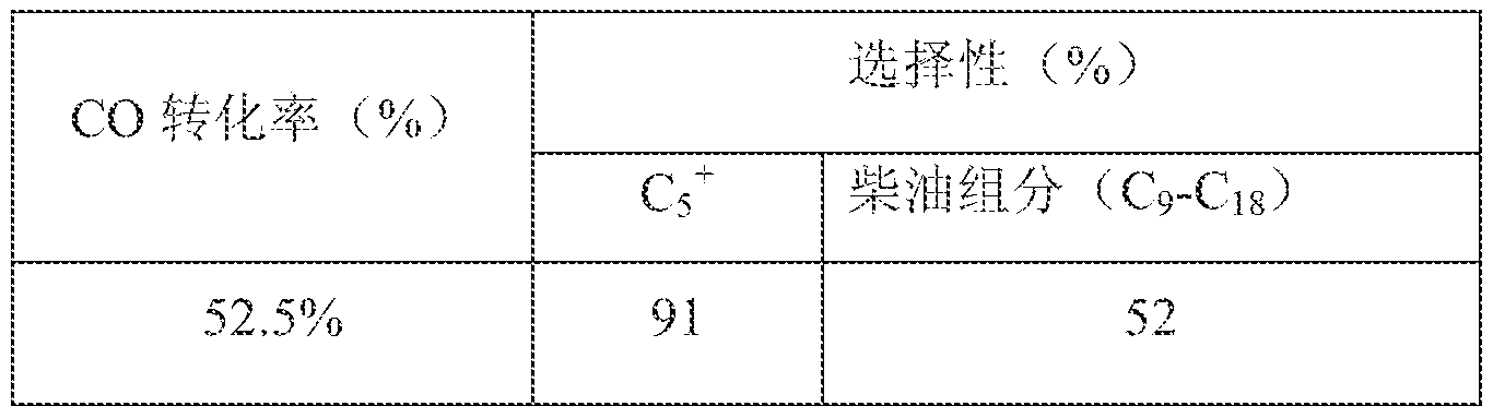
利用超重力反应器进行费托合成制汽油反应。合成气为 CO+H2的混合气, CO/H2=l/2 o 将 Ru/Si02费托催化剂放入网状支撑件内, 固定于超重力反应器的转子上。 采用热管换热立式超 重力反应器, 见图 5。 热管为钢材料, 换热介质为空气, 换热介质的流速为 1升 /分钟。
反应的工艺条件如下:
合成气空速: SOOh"1 , 反应温度; 210TJ , 反应压力: 0,5MPa
催化剂床层转速: 2500rpm, 催化剂床层超重力水平: i 50g
超重力反应器进行费托合成制汽油反应结果-

反应的工艺条件如下- 合成气空速; 7500h- 反应温度: 250 °C , 反应压力: 2,5MPa
催化剂床层转速: 5000rpm, 催化剂床层超重力水平: 250g
超重力反应器进行费托合成制低碳烯烃反应结果-

利用超重力反应器进行费托合成制炔烃反应。 合成气为 CO+H2的混合气, CO/H2=l/2。将 C0/Si02费托催化剂放入网状支撑件内, 固定于超重力反应器的转子上, 采用热管换热立式超 重力反应器, 见图 5。 热管为铜材料, 换热介质为空气, 换热介质的流速为 3 †/分钟。
反应的工艺条件如下:
合成气空速: SOOOh"5 , 反应温度: 350 反应压力: 0.6MPa
催化剂床层转速: 8500r ni, 催化剂床层超重力水平: 4(K)g


利用超重力反应器迸行费托合成制炔烃反应。合成气为 CO+H2的混合气, CO/H2=l/l。将 铁基费托催化剂放入网状支撑件内, 固定干超重力反应器的转子上。 采用热管换热立式超重 力反应器, 见图 5„ 热管为铜材料换热介质为空气换热介质的流速为 2升 /分钟
反应的工艺条件如下:
合成气空速: 1000h 反应温度: 210°C ? 反应压力: 2.0MPa
催化剂床层超重力水平: 350g
超重力反应器进行费托合成制炔烃反应结果:
选择性 (%)
CO转化率 (%)
c5 + 炔烃组分 (乙炔)
65.5% 29 1 1
Claims
1、 一种用于调变费托合成产物分布的超重力旋转填充床催化反应器, 包括密闭 的反应器壳体、 固定有催化剂床层的转子、 转轴、 端盖、 反应物的进口、 产物 的出口, 其特征在于, 催化反应器转子中布置有多层同心环式催化剂床层, 催 化剂层和端盖之间密封, 每两层催化剂床层间分布有同心环式的层间换热段, 可及时移出反应热; 间隔有层间换热段的两层催化剂床层是相通的, 反应物是 连续通过多个催化剂床层, 从而使每层催化剂都能接触到反应物料, 反应物的 进口位于转子的中心, 壳体上开有产物出口, 转子外缘设有 片, 用于将未反 应的气体物料及产物输送到气体出口管, 层间换热段为相间隔的多个套管或热 管围绕转子中心组成的同心圆环, 端盖上设有换热介质进口和出口装置。
2、 按照权利要求 1的反应器, 其特征在于, 催化剂床层分 2层或多层固定在转 子上, 每两层环热层间均有层间换热段, 换热段沿转子的径向同心分布; 热管 的外表面垂直于轴向布置有换热翅片, 套管为带翅片的套管。
3、 按照权利要求 1的反应器, 其特征在于, ί司心环式催化剂床层为固定在转子 上的包覆有催化剂颗粒的同心环式丝网层或者固载有催化剂活性组分的同心环 整体结构式填料。
4、 按照权利要求 1的反应器, 其特征在于, 层间换热段为套管时, 换热介质的 进口和出口装置为平行于端盖叠放着的两块与转子 ί司心的圆板, 两圆板和端盖 相互之间有空间间隔, 两圆板的周边固定并密封在端盖上, 套管的最外层垂直 密封地固定在端盖上, 套管的内管端口穿过靠近端盖的圆板并密封固定在圆板 上, 并且在此圆板上开设有换热介质进口管, 换热介质进口管穿过最外面的圆 板, 最外面的圆板上设有换热介质出口管, 换热介质通过套管移除热;
层间换热段为热管时, 换热介质的进口和出口装置为平行于端盖、 四周密 封固定于端盖的、 与转子同心的圆板, 在此圆板的直径的两端设有换热介质进 口管和出口管, 热管密封固定在端盖上, 一端位于层间换热段, 另一端位于端 盖和圆板之间, 换热介质通过端盖和圆板之间热管移出热。
5、按照权利要求 i的反应器, 其特征在于, 热管或套管的制备材料为: 钢, 蒙耐合金, 英科耐尔合金, 铝、 钛、 镍、 铜、 黄铜或任意前述金属的合金, 高 分子材料, 陶瓷, 玻璃, 包含高分子村料和玻璃纤维的复合材料, 石英, 硅, 上述物质中的一种、 两种或几种的组合;
转子的制备材料为: 钢、 蒙耐合金、 英科耐尔合金、 铝、 钛、 镍、 铜、 黄 铜、 或任意前述金属的合金; 高分子 ^料、 陶瓷、 玻璃、 包含高分子材料和玻 璃纤维的复合材料、 石英、 硅、 或其两种或多种的结合。
6、 按照权利要求 1的反应器, 其特征在于, 为卧式的, 产物出口设在转子旋转 的切 方向。
7、 按照权利要求 1的反应器, 其特征在于, 为立式的, 在立式旋转填充床催化 反应器在密封的壳体和转子之间设有下推 ^片, 产品出口设置在壳体上转轴的 位置, 并且在出口处设有轴流元件。
8、 按照权利要求 1-7所述的任一的反应器, 其特征在于, 为套管换热卧式超重 力反应器、 带翅片的套管换热卧式超重力反应器、 热管换热卧式超重力反应器 或热管换热立式超重力反应器。
9、 利用权力要求 1所述的反应器调变费托合成产物分布的方法, 其特征在于, 包括以下歩骤: 费托合成反应的催化剂安装在转子的催化剂床层中, 反应过程 中催化剂床层始终处于高速旋转状态, 换热介质采用液体或气体, 通过换热介 质的进口进入, 换热后, 通过换热介质出口排除, 反应物料由反应物进口进入, 通过高速旋转的催化剂床层和层间换热段, 生成的产物由产物出口 出; 反应 物料为煤基合成气、 天然气基合成气、 煤层气基合成气或生物质基合成气, 其 组成为各种比例的 CO C02- K¾, CO+¾, C02+¾: 旋转填充床催化反应器的超 重力水平为 2 400g; 反应温度为 80Ό 500Ό, 反应压力为 ] ί lOOatm, 气体空速 为 100- 100000h 。
Applications Claiming Priority (2)
| Application Number | Priority Date | Filing Date | Title |
|---|---|---|---|
| CN201210081986.0 | 2012-03-26 | ||
| CN201210081986.0A CN102626600B (zh) | 2012-03-26 | 2012-03-26 | 一种调变费托合成产物分布的反应器及应用 |
Publications (1)
| Publication Number | Publication Date |
|---|---|
| WO2013143243A1 true WO2013143243A1 (zh) | 2013-10-03 |
Family
ID=46585101
Family Applications (1)
| Application Number | Title | Priority Date | Filing Date |
|---|---|---|---|
| PCT/CN2012/079015 Ceased WO2013143243A1 (zh) | 2012-03-26 | 2012-07-23 | 一种调变费托合成产物分布的超重力旋转填充床催化反应器及应用 |
Country Status (2)
| Country | Link |
|---|---|
| CN (1) | CN102626600B (zh) |
| WO (1) | WO2013143243A1 (zh) |
Cited By (3)
| Publication number | Priority date | Publication date | Assignee | Title |
|---|---|---|---|---|
| US20220363997A1 (en) * | 2019-02-15 | 2022-11-17 | Other Lab, Llc | Centrifuge reactor system and method |
| US12383846B2 (en) | 2023-03-09 | 2025-08-12 | Schlumberger Technology Corporation | Method and design of multiple counterrotating unit reactor |
| US12582955B2 (en) | 2023-03-09 | 2026-03-24 | Schlumberger Technology Corporation | Method and design of heat effective rotated packed bed |
Families Citing this family (11)
| Publication number | Priority date | Publication date | Assignee | Title |
|---|---|---|---|---|
| CN102872788B (zh) * | 2012-09-03 | 2015-01-07 | 神华集团有限责任公司 | 一种超重力多功能反应器 |
| CN103285781B (zh) * | 2013-06-27 | 2015-06-24 | 常州大学 | 一种超重力水合物合成装置 |
| CN104549100A (zh) * | 2013-10-16 | 2015-04-29 | 北京化工大学 | 一种新型无源的超重力旋转床装置 |
| FR3063441B1 (fr) * | 2017-03-01 | 2021-10-01 | Ifp Energies Now | Reacteur comprenant des lits catalytiques de faible epaisseur. |
| CN109529905B (zh) * | 2018-12-21 | 2022-03-04 | 陕西师范大学 | 一种Co基催化剂可控调变费托反应产物分布的方法 |
| TWI694858B (zh) * | 2019-08-19 | 2020-06-01 | 智和股份有限公司 | 廢氣超重力淨化裝置 |
| CN113368793B (zh) * | 2020-02-25 | 2022-12-27 | 北京化工大学 | 一种用于热敏物质精确控温的旋转设备及其应用方法 |
| CN113477188B (zh) * | 2021-07-02 | 2023-08-29 | 北京化工大学 | 一种浸没式旋转填充床反应器及应用 |
| CN113716946B (zh) * | 2021-08-23 | 2022-06-03 | 西安交通大学 | 一种3d打印可组装整体式催化剂及其制备方法 |
| CN118045536B (zh) * | 2024-04-16 | 2024-06-11 | 天津凯莱英医药科技发展有限公司 | 锌还原连续反应系统及方法 |
| CN118681499B (zh) * | 2024-07-22 | 2025-10-10 | 浙江工业大学 | 一种超重力式连续流反应器 |
Citations (5)
| Publication number | Priority date | Publication date | Assignee | Title |
|---|---|---|---|---|
| US20020086910A1 (en) * | 2000-12-13 | 2002-07-04 | Trinh Sinh Han | Rotating annular catalytic reactor |
| CN1438067A (zh) * | 2003-03-06 | 2003-08-27 | 上海交通大学 | 具有新型转子结构的旋转床超重力场装置 |
| CN2654194Y (zh) * | 2003-04-08 | 2004-11-10 | 薛碧 | 强化传质的旋转床超重力机 |
| CN101549274A (zh) * | 2008-04-01 | 2009-10-07 | 北京化工大学 | 一种超重力旋转床装置及在二氧化碳捕集纯化工艺的应用 |
| CN102234212A (zh) * | 2010-04-20 | 2011-11-09 | 中国石油化工股份有限公司 | 合成气直接转化为低碳烯烃的方法 |
Family Cites Families (3)
| Publication number | Priority date | Publication date | Assignee | Title |
|---|---|---|---|---|
| CN2782685Y (zh) * | 2005-04-21 | 2006-05-24 | 中国石油天然气股份有限公司 | 费托合成油径向反应器 |
| CN102258880B (zh) * | 2011-06-09 | 2013-05-29 | 北京化工大学 | 一种分段进液强化转子端效应的超重力旋转床装置 |
| CN202638399U (zh) * | 2012-03-26 | 2013-01-02 | 北京化工大学 | 一种调变费托合成产物分布的反应器 |
-
2012
- 2012-03-26 CN CN201210081986.0A patent/CN102626600B/zh active Active
- 2012-07-23 WO PCT/CN2012/079015 patent/WO2013143243A1/zh not_active Ceased
Patent Citations (5)
| Publication number | Priority date | Publication date | Assignee | Title |
|---|---|---|---|---|
| US20020086910A1 (en) * | 2000-12-13 | 2002-07-04 | Trinh Sinh Han | Rotating annular catalytic reactor |
| CN1438067A (zh) * | 2003-03-06 | 2003-08-27 | 上海交通大学 | 具有新型转子结构的旋转床超重力场装置 |
| CN2654194Y (zh) * | 2003-04-08 | 2004-11-10 | 薛碧 | 强化传质的旋转床超重力机 |
| CN101549274A (zh) * | 2008-04-01 | 2009-10-07 | 北京化工大学 | 一种超重力旋转床装置及在二氧化碳捕集纯化工艺的应用 |
| CN102234212A (zh) * | 2010-04-20 | 2011-11-09 | 中国石油化工股份有限公司 | 合成气直接转化为低碳烯烃的方法 |
Cited By (4)
| Publication number | Priority date | Publication date | Assignee | Title |
|---|---|---|---|---|
| US20220363997A1 (en) * | 2019-02-15 | 2022-11-17 | Other Lab, Llc | Centrifuge reactor system and method |
| US12139677B2 (en) * | 2019-02-15 | 2024-11-12 | Other Lab, Llc | Centrifuge reactor system and method |
| US12383846B2 (en) | 2023-03-09 | 2025-08-12 | Schlumberger Technology Corporation | Method and design of multiple counterrotating unit reactor |
| US12582955B2 (en) | 2023-03-09 | 2026-03-24 | Schlumberger Technology Corporation | Method and design of heat effective rotated packed bed |
Also Published As
| Publication number | Publication date |
|---|---|
| CN102626600A (zh) | 2012-08-08 |
| CN102626600B (zh) | 2014-05-21 |
Similar Documents
| Publication | Publication Date | Title |
|---|---|---|
| WO2013143243A1 (zh) | 一种调变费托合成产物分布的超重力旋转填充床催化反应器及应用 | |
| Huang et al. | High-performance Ni–Fe redox catalysts for selective CH4 to syngas conversion via chemical looping | |
| CN109499486B (zh) | 一种烷烃催化脱氢或催化裂解制烯烃循环流化床反应装置 | |
| CN102559234B (zh) | 一种选择性调控费托合成产品的方法 | |
| CN102504858B (zh) | 一种费托合成定向合成汽油柴油的方法 | |
| CN102234212A (zh) | 合成气直接转化为低碳烯烃的方法 | |
| CN106215828A (zh) | 一种微通道反应装置、微通道反应系统及制备烯烃的方法 | |
| CN104437335B (zh) | 一种快速移热旋转填料床传质与反应设备 | |
| CN202638399U (zh) | 一种调变费托合成产物分布的反应器 | |
| CN104557423A (zh) | 一种甲烷直接转化制芳烃的方法 | |
| CN103228766B (zh) | 天然气的转化 | |
| CN102503769B (zh) | 一种合成气合成混合醇的方法 | |
| CN205761060U (zh) | 重整反应器 | |
| CN104341259B (zh) | 一种合成气催化甲烷化方法及装置 | |
| NO177492B (no) | Fremgangsmåte for katalytisk fremstilling av hydrokarboner med minst 2 karbonatomer | |
| CN105439790A (zh) | 一种由苯和甲醇制备异构级二甲苯的方法 | |
| CN106608779B (zh) | 催化裂解生产丙烯的方法 | |
| CN107899519B (zh) | 一种用于费托合成的系统及合成气制备低碳烯烃的方法 | |
| Meng et al. | Review of slurry bed reactor for carbon one chemistry | |
| CN204455003U (zh) | 一种轻烃裂解设备 | |
| CN204320317U (zh) | 一种快速移热旋转填料床传质与反应设备 | |
| CN108017488A (zh) | 醇和/或醚原料催化转化制芳烃的方法 | |
| CN103540334A (zh) | 一种基于原位温度调控的费托合成反应方法 | |
| US20130084223A1 (en) | Three phase reactor | |
| NO177665B (no) | Fremgangsmåte for omdannelse av et gassformig produkt og et apparat for anvendelse i fremgangsmåten |
Legal Events
| Date | Code | Title | Description |
|---|---|---|---|
| 121 | Ep: the epo has been informed by wipo that ep was designated in this application |
Ref document number: 12872745 Country of ref document: EP Kind code of ref document: A1 |
|
| NENP | Non-entry into the national phase |
Ref country code: DE |
|
| 122 | Ep: pct application non-entry in european phase |
Ref document number: 12872745 Country of ref document: EP Kind code of ref document: A1 |