WO2013141017A1 - 多方向移動体モジュール - Google Patents
多方向移動体モジュール Download PDFInfo
- Publication number
- WO2013141017A1 WO2013141017A1 PCT/JP2013/055995 JP2013055995W WO2013141017A1 WO 2013141017 A1 WO2013141017 A1 WO 2013141017A1 JP 2013055995 W JP2013055995 W JP 2013055995W WO 2013141017 A1 WO2013141017 A1 WO 2013141017A1
- Authority
- WO
- WIPO (PCT)
- Prior art keywords
- chain
- drive
- moving
- driving
- vector
- Prior art date
- Legal status (The legal status is an assumption and is not a legal conclusion. Google has not performed a legal analysis and makes no representation as to the accuracy of the status listed.)
- Ceased
Links
Images












Classifications
-
- B—PERFORMING OPERATIONS; TRANSPORTING
- B62—LAND VEHICLES FOR TRAVELLING OTHERWISE THAN ON RAILS
- B62D—MOTOR VEHICLES; TRAILERS
- B62D15/00—Steering not otherwise provided for
-
- B—PERFORMING OPERATIONS; TRANSPORTING
- B62—LAND VEHICLES FOR TRAVELLING OTHERWISE THAN ON RAILS
- B62D—MOTOR VEHICLES; TRAILERS
- B62D55/00—Endless track vehicles
- B62D55/08—Endless track units; Parts thereof
- B62D55/18—Tracks
- B62D55/20—Tracks of articulated type, e.g. chains
- B62D55/205—Connections between track links
- B62D55/21—Links connected by transverse pivot pins
-
- B—PERFORMING OPERATIONS; TRANSPORTING
- B62—LAND VEHICLES FOR TRAVELLING OTHERWISE THAN ON RAILS
- B62D—MOTOR VEHICLES; TRAILERS
- B62D55/00—Endless track vehicles
- B62D55/08—Endless track units; Parts thereof
- B62D55/18—Tracks
- B62D55/26—Ground engaging parts or elements
Definitions
- the present invention relates to a moving mechanism applied to a moving means for a passenger and a conveying means for conveying an object to be conveyed, and particularly to a multidirectional moving body module that obtains a driving force and smoothly moves and turns.
- a moving mechanism that changes the moving direction by steering a rotating body
- a vehicle that includes a pair of left and right front wheels and a rear wheel and turns the direction of the vehicle body by steering the front wheels or the like to change the moving direction of the vehicle
- a moving direction is changed by a method of moving a moving body by an endless track provided in a pair of left and right on a moving body such as a vehicle or a roller body provided on a wheel body, and a wheel having two support members A wheel in which the rotation shafts of a large number of roller bodies arranged between the support members and at least partially projecting from the circumference of the support members are inclined with respect to the rotation shaft of the wheel body.
- roller driving element that includes a central body, a roller unit having an endless shape, and a driving unit that engages with the roller unit and drives a chain that is a roller unit with respect to the central body (for example, Patent Document 2) reference.).
- the roller driving element having a chain which is a roller unit constituting an endless shape as in Patent Document 2 described above the roller driving element is drawn out to the grounding surface side of the moving body on the moving surface side of the chain and driven linearly. Since the chain part to be subjected to stress from the moving surface, the chain part extended to the moving surface side bends easily, and the chain contact part with the grounding surface tends to wear, resulting in a decrease in chain life. There was a point. In order to prevent the above-mentioned chain portion from being bent, when a chain is excessively tensioned and kept linear, a complicated tension applying mechanism that continuously applies excessive tension to the chain is provided. There is a problem in that it is difficult to save space as the cost of parts increases.
- the technical problem to be solved by the present invention is to make the steering mechanism more complicated, the center of gravity of the moving mechanism to be higher, the deflection of the chain portion extended to the moving surface side, and the chain life.
- a movable body module main body that moves on a moving surface, driving sprockets and follower members that are provided on the front and rear sides of the movable body module main body, and the left and right driving members.
- a pair of drive chains that are driven to freely move left and right independently while being wound around the sprocket and the driven member, and are arranged to rotate along the drive direction of the drive chain on the outer peripheral side of the drive chain.
- a plurality of rotating bodies each having an axis that contacts the outer peripheral surface with the moving surface, and fixed to each other in a state of being arranged on the outer peripheral side of the drive chain.
- a plurality of chain bending restricting block bodies which can be freely contacted, and the rotation shaft of the rotating body is inclined at a predetermined angle with respect to the driving direction of the driving chain.
- the inclination of the rotating shaft of the rotating body has a line-symmetrical relationship with respect to the line in the front-rear direction of the movable body module body in the pair of left and right driving chains, and the driving chain is driven in the posture.
- the chain bending restricting block body is a pair of wall-like members installed on the side of the rotating body. It is composed of a block body, and the outer side surface of the wall-shaped block body is formed closer to the inner periphery of the drive chain than the contact line that contacts the moving surface on the outer peripheral surface of the rotating body.
- the chain bending restricting block body is a fixing base portion that fixes the rotating body to the drive chain.
- the rotation axis of the rotating body provided on one of the pair of drive chains and the pair of drive chains is inclined by 45 ° with respect to the drive direction of the drive chain, thereby further solving the above-described problems.
- the multidirectional moving body module of the present invention includes a moving body module body that moves on a moving surface, driving sprockets and driven members that are provided on the front and rear sides of the moving body module body, and left and right driving members.
- a pair of drive chains that are driven so as to be able to move forward and backward independently while being wound around the sprocket and the driven member, and a rotary shaft that is rotatably disposed along the drive direction of the drive chain on the outer peripheral side of the drive chain.
- a plurality of rotating bodies that contact the outer peripheral surface with the moving surface, and the rotating shaft of the rotating body is inclined at a predetermined angle with respect to the drive direction of the drive chain, and the rotating body rotates.
- the inclination of the shaft has a symmetrical relationship with respect to the line in the front-rear direction of the moving body module body in the pair of left and right drive chains.
- Move in the front-rear direction by canceling the component force move in various directions by reducing or increasing the component force in the left-right direction, and rotate by shifting the force action line with respect to the center of gravity of the multi-directional mobile module.
- the opposed end faces can be brought into contact with each other according to the change in the posture of the drive chain, being fixed in a state of being arranged on the outer peripheral side of the drive chain.
- a plurality of chain bending restricting block bodies, and when the attitude of the drive chain is bent along the outer periphery of the drive sprocket and the driven member, the opposing end faces adjacent to each other in the chain longitudinal direction of the chain bending restriction block body are A configuration in which opposed end surfaces adjacent to each other in the chain longitudinal direction of the block body for regulating chain bending contact each other in the chain longitudinal direction when the chain is separated from each other in the longitudinal direction of the chain and the driving chain is linear in the longitudinal direction of the chain.
- the driving force can be sufficiently transmitted to the moving surface.
- the wear of the drive chain is suppressed, and the load is dispersed and the load on each rotating body is reduced by supporting the entire load by constantly contacting a plurality of rotating bodies on the moving surface.
- the center of gravity which tends to increase the complexity and the movement mechanism, and the deterioration of the chain life can be prevented.
- the load on the rotating body can be reduced, the number of parts can be reduced, and the space can be saved, and a sufficient driving force can be obtained to smoothly move and rotate.
- the pair of walls in which the block body for restricting chain bending is installed on the side of the rotating body
- the chain longitudinal outer side surface of the wall-shaped block body is formed closer to the inner periphery of the drive chain than the contact line that contacts the moving surface on the outer peripheral surface of the rotating body.
- the chain bending restricting block body is a fixing pedestal portion that fixes the rotating body to the drive chain.
- the fixing base part can be freely replaced when the rotating body is replaced, so that the maintenance cost can be reduced.
- the drive directions of the pair of drive chains are parallel to each other, Since the drive speed of the pair of drive chains is controlled and the moving speed and direction of the movable body module body can be adjusted freely, a sufficient drive force is obtained by a simple drive control system and method, and smooth in multiple directions, and It can be freely moved and turned.
- the rotation axis of the rotating body provided on one of the pair of drive chains and the pair of drive chains Since the rotation axis of the rotating body provided on the other side of the shaft is inclined by 45 ° with respect to the drive direction of the drive chain, it is divided into a component force in the front-rear direction and a component force in the left-right direction.
- the moving torque can be obtained uniformly in all directions including the front-rear direction and the left-right direction.
- FIG. 3B is an enlarged view of a portion indicated by reference numeral 3B shown in FIG. 3A.
- the conceptual diagram of the multidirectional moving body module of the Example of this invention. The conceptual diagram which showed the some rotary body by the side of a moving surface in FIG.
- the multidirectional moving body module of the present invention includes a moving body module main body that moves on a moving surface, driving sprockets and driven members that are provided on the front and rear sides of the moving body module main body, and left and right driving drives.
- a pair of drive chains that are driven to freely move left and right independently while being wound around the sprocket and the driven member, and a rotary shaft that is rotatably disposed along the drive direction of the drive chain on the outer peripheral side of the drive chain.
- a plurality of rotating bodies each having an outer peripheral surface in contact with the moving surface, and fixed in a state of being arranged on the outer peripheral side of the drive chain, and can be brought into contact with each other according to a change in the posture of the drive chain.
- a plurality of chain bending restriction block bodies and the rotating shaft of the rotating body is inclined at a predetermined angle with respect to the driving direction of the driving chain.
- the inclination of the rotating shaft of the rotating body has a symmetrical relationship with the pair of left and right drive chains with respect to the front-rear direction line in the movable body module body, and the attitude of the driving chain is the driving sprocket and
- the opposed end faces in the chain longitudinal direction of the chain bending restricting block body are separated from each other in the chain longitudinal direction, and the posture of the drive chain is linear in the chain longitudinal direction.
- the opposite end faces of the chain bending restriction block body in the longitudinal direction of the chain are in contact with each other in the longitudinal direction of the chain, and the center of gravity and the moving surface side tend to make the steering mechanism complicated and the moving mechanism tend to be high.
- the load on the rotating body is reduced, the number of parts is reduced, and space is saved. Achieved, as long as it smoothly move and turn to obtain a sufficient driving force, aspects of the specific implementation may any be any one.
- the “pitch corresponding to the arrangement pitch of the plurality of rotating bodies” in the present invention means a regular interval as in the arrangement pitch of the plurality of rotating bodies. This is not limited to the case where it is equal to the arrangement pitch of the plurality of rotating bodies, and may be an integer multiple pitch of the arrangement pitch of the plurality of rotating bodies, or may be 1/2 pitch.
- the “side of the rotating body” in the present invention means at least one side of the rotating body along the width direction of the drive chain.
- the plurality of rotating bodies used in the present invention includes at least two rotating bodies adjacent to each other along the driving direction of the drive chain among the plurality of rotating bodies, and this set is periodically arranged at regular intervals. They may be arranged so as to realize the arranged state.
- the rotating bodies arranged in each of the pair of drive chains may be arranged in a staggered manner as a whole by arranging them in a staggered manner along the drive direction of the drive chain.
- a plurality of pairs of drive chains used in the present invention may be provided in the drive direction of the drive chain, or may be provided in the width direction of the drive chain.
- the driven member used in the present invention may be a driven sprocket having the same shape as the driving sprocket that drives the driving chain, or the driven member is rotated by the driving of the driving chain with the driving chain wound around the outer peripheral surface.
- a cylindrical member may be sufficient.
- driving the drive chain 120 in the forward direction means that the lower side portion, which is the moving surface side portion, which is the ground plane side portion of the drive chain 120, is driven in the backward direction B and the upper side of the drive chain 120.
- Driving the drive chain 120 in the reverse direction means driving the entire drive chain 120 in the reverse direction with respect to the normal direction described above.
- the driving sprocket 111 and the driven member 112 provided on the front and rear of the mobile module main body 110 in order to distinguish the driving sprocket 111 and the driven member 112 provided on the front and rear of the mobile module main body 110 from the front and the rear, the driving sprocket 111 and the driven member 112 provided on the right and the front are used for driving.
- the sprocket 111RF and the driven member 112RB are used.
- the reference members 112 and the driving sprockets 111 provided on the left and right sides are replaced with reference numerals as the driven member 112LF and the driving sprocket 111LB.
- the multidirectional moving body module 100 includes a moving body module main body 110 that moves on the moving surface G, and driving sprockets provided on the left and right sides of the moving body module main body 110.
- 111RF, 111LB and driven members 112RB, 112LF are disposed on the driving sprocket 111RF
- the driving sprocket 111LB is disposed on the left rear side
- the driven member 112RB is disposed on the right rear side
- the driven member 112LF is disposed on the left front side.
- a pair of drive chains 120 and 120 that are driven to freely move forward and backward independently in a state of being wound around the drive sprocket 111RF and the driven member 112RB, and the drive sprocket 111LB and the driven member 112LF, respectively,
- a plurality of rotating bodies 130 that are rotatably disposed along the driving direction of the drive chain 120 on the outer peripheral side of the chain 120, have a rotating shaft 131, and contact the outer peripheral surface 130S with the moving surface G, respectively, and the drive chain 120
- Fixed base portions that are examples of a plurality of chain bending restricting block bodies that are fixed in a state in which they are arranged on the outer peripheral side of each other and that can be brought into contact with each other according to a change in the posture of the drive chain 120. 140A.
- the rotating shaft 131 of the rotating body 130 is inclined at a predetermined angle with respect to the driving direction of the driving chain 120, and the inclination of the rotating shaft 131 of the rotating body 130 is moved by the pair of left and right driving chains 120.
- the body module body 110 has a line-symmetric relationship with respect to the front-rear direction line. As a result, as will be described in detail later, the component force in the left-right direction is canceled and moved in the front-rear direction, or the component force in the left-right direction is reduced or increased to move in various directions.
- the multi-directional moving body module 100 can be rotated by generating a rotational moment with respect to the center of gravity C of the multi-directional moving body module 100.
- the opposite end surfaces 141AS and 141AS adjacent to each other in the longitudinal direction of the chain of the fixing base portion 140A are It is the structure which mutually contacts in the chain longitudinal direction.
- the chain portion of the drive chain 120 that is drawn out toward the moving surface G becomes a straight line, and one fixing pedestal portion 140A comes into contact with the adjacent fixing pedestal portion 140A in the chain longitudinal direction and is drawn out.
- the bending of the driving sprocket 111 and the driven member 112 in the chain portion to the opposite side to the side along the outer periphery is restricted.
- the bending from the endless outer periphery of the chain portion extended toward the moving surface G toward the inner periphery (the bending from the endless outer periphery indicated by the phantom line in FIG. 3 toward the inner periphery) is restricted.
- the wear of the drive chain 120 is suppressed, and the plurality of rotating bodies 130 are always in contact with the moving surface G to support the entire load, so that the load is dispersed and the load load per rotating body is reduced.
- the drive chain 120 includes an inner link unit formed by press-fitting a pair of front and rear bushes 124 to a pair of left and right inner plates 121, and an outer plate disposed outside the inner link unit. 122, a plurality of connecting pins 123 for press-fitting and fitting the inner link unit and the outer plate 122 in the longitudinal direction of the chain by being press-fitted to the outer plate 122, and a roller 125 loosely fitting a bush 124. Yes. Even if the drive chain 120 is not provided with the roller 125, there is no problem in its operation.
- the drive shaft 114RF and the drive shaft 114LB are configured to drive the drive chain 120 independently without being connected to each other.
- the driven shaft 114LF and the driven shaft 114RB are not connected to each other.
- the drive motor 113F drives the drive sprocket 111RF.
- power is transmitted by the drive chain 120, and the driven member 112RB is driven to rotate in accordance with the driving of the driving sprocket 111RF.
- the drive motor 113B drives the drive sprocket 111LB.
- power is transmitted by the drive chain 120, and the driven member 112LF is driven to rotate according to the drive of the drive sprocket 111LB. That is, the drive chains 120 and 120 arranged on the left and right in the drawing are driven independently of each other.
- both the front and rear drive motors 113F and 113B are arranged to balance the weight of the multidirectional driver module 100 and to secure a motor installation space. Is realized.
- the fixing base portion 140 ⁇ / b> A for fixing the rotating body 130 used in the multidirectional moving body module 100 to the drive chain 120 is an example of a chain bending restricting block body. Thereby, when the rotating body 130 is replaced, the fixing pedestal portion 140A can be replaced. That is, the multidirectional moving body module 100 is configured to reduce maintenance costs.
- the driving directions of the pair of driving chains 120 and 120 used in the multidirectional moving body module 100 are parallel to each other. As a result, the driving direction and driving speed of each of the pair of driving chains 120 and 120 are controlled so that the moving speed and the direction of the movable body module main body 110 can be adjusted. That is, the multidirectional moving body module 100 is configured to obtain a sufficient driving force by a simple drive control system and method, and to smoothly move and rotate in multiple directions.
- the rotation axis 131 ⁇ / b> A of the rotating body 130 provided on one of the pair of driving chains 120 and 120 used in the multidirectional moving body module 100 and the other of the pair of driving chains 120 and 120 are provided.
- the rotation axis 131A of the rotating body 130 intersects with each other. Specifically, the rotating shaft 131 of the rotating body 130 is inclined at a predetermined angle with respect to the driving direction of the driving chain 120, and the inclination of the rotating shaft 131 of the rotating body 130 is determined by a pair of left and right driving chains.
- Reference numeral 120 denotes a line-symmetric relationship with respect to the line in the front-rear direction in the mobile module main body 110.
- the multidirectional moving body module 100 is moved in the front-rear direction by canceling the left and right direction component forces, or the multidirectional moving body module 100 is moved in various directions by reducing or increasing the left and right direction component forces.
- the multi-directional mobile module 100 can be rotated by generating a rotational moment by shifting the force acting line with respect to the center of gravity C of the multi-directional mobile module 100.
- the rotation axis 131 ⁇ / b> A of the rotating body 130 provided on one of the pair of driving chains 120, 120 used in the multidirectional moving body module 100 is inclined by 45 ° with respect to the driving direction of the driving chain 120. Yes.
- the rotation axis 131 ⁇ / b> A of the rotating body 130 provided on the other side is inclined by 45 ° with respect to the drive direction of the drive chain 120.
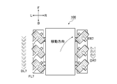
- FIGS. 1 to 13B For convenience of explanation, the forward direction F, the backward direction B, the right R, and the left L of the multidirectional moving body module 100 are indicated by arrows in FIGS. 1, 5 to 13B.
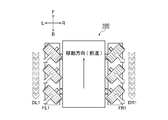
- the white arrows D (DR1, DR2,..., DL1, DL2,...) Shown in FIGS. 1, 3A, 7A to 13A are on the moving surface G side of the drive chain 120 having an endless endless track. It is the velocity vector of the lower part facing.
- This velocity vector is based on the multidirectional moving body module 100. More specifically, for example, the speed vector D of the lower portion of the drive chain 120 shown in FIG. 1 facing the moving surface G is equal to the speed vectors DR1 and DL1 of the drive chain 120 shown in FIG. 7A. I'm doing it.
- the moving direction of the multidirectional moving body module 100 shown below is an example, and the multidirectional moving body module 100 moves by changing the combination of the magnitudes and directions of the respective velocity vectors of the pair of drive chains 120 and 120. It can move in various directions within the plane G.
- FIG. 7A and 7B show the case where the speed vector DR1 of the right drive chain 120 and the speed vector DL1 of the left drive chain 120 have the same magnitude and their directions are the backward direction B.
- the acting force vectors FR1 and FL1 act from the outer peripheral surface 130S of each rotating body 130 to the moving surface G.
- the acting force vector FR1 is a vector that acts on the moving surface G from the outer peripheral surface 130S of the rotating body 130 of the right drive chain 120.
- the acting force vector FL1 is a vector acting from the outer peripheral surface 130S of the rotating body 130 of the left drive chain 120 to the moving surface G.
- the rotation shaft 131 of the rotating body 130 of the right drive chain 120 is inclined 45 ° with respect to the drive direction while the right side is inclined backward and the left side is inclined forward.
- the direction of the speed vector DR1 of the right drive chain 120 is the backward direction B. Accordingly, as shown in FIGS. 7A and 7B, the acting force vector FR1 is directed from the left front to the right rear while being inclined by 45 ° with respect to the driving direction.
- the rotation shaft 131 of the rotating body 130 of the left drive chain 120 is inclined 45 ° with respect to the drive direction while the right side is inclined forward and the left side is inclined backward.
- the direction of the speed vector DL1 of the left drive chain 120 is the backward direction B. Accordingly, as shown in FIGS. 7A and 7B, the acting force vector FL1 is directed from the right front to the left rear while being inclined by 45 ° with respect to the driving direction.
- the component force of the acting force vector FR1 in the left-right direction and the component force of the acting force vector FL1 in the left-right direction are equal, the directions are opposite to each other, and are on the same line.
- the rightward leftward component of FR1 and the leftward leftward component of action force vector FL1 cancel each other.
- the component force of the action force vector FR1 in the front-rear direction and the component force of the action force vector FL1 in the front-rear direction are the same, and the directions are the same.
- the position is symmetrical with respect to the center of gravity C of the multidirectional moving body module 100.
- the direction of the resultant force vector FA1 which is the sum of the acting force vector FR1 and the acting force vector FL1 is the backward direction B, and the center of gravity C of the multidirectional mobile module 100 is located on the line of the resultant force vector FA1.
- the direction of the reaction force FB1 acting on the moving body module 100 from the moving surface G is the forward direction F
- the center of gravity C of the multidirectional moving body module 100 is positioned on the line of the reaction force FB1. That is, no moment of force (rotational force) is generated. For this reason, the multidirectional moving body module 100 moves in the forward direction F.
- FIG. 8A and 8B show a case where the speed vector DR2 of the right drive chain 120 and the speed vector DL2 of the left drive chain 120 have the same magnitude and their directions are the forward direction F.
- the acting force vectors FR2 and FL2 act from the outer peripheral surface 130S of each rotating body 130 to the moving surface G.
- the acting force vector FR2 is a vector acting from the outer peripheral surface 130S of the rotating body 130 of the right drive chain 120 to the moving surface G.
- the acting force vector FL2 is a vector acting from the outer peripheral surface 130S of the rotating body 130 of the left drive chain 120 to the moving surface G.
- the rotation shaft 131 of the rotating body 130 of the right drive chain 120 is inclined 45 ° with respect to the drive direction while the right side is inclined backward and the left side is inclined forward.
- the direction of the speed vector DR2 of the right drive chain 120 is the forward direction F. Therefore, as shown in FIGS. 8A and 8B, the acting force vector FR2 is directed from the right rear to the left front in a state inclined by 45 ° with respect to the driving direction.
- the rotation shaft 131 of the rotating body 130 of the left drive chain 120 is inclined 45 ° with respect to the drive direction while the right side is inclined forward and the left side is inclined backward.
- the direction of the speed vector DL2 of the left drive chain 120 is the forward direction F. Accordingly, as shown in FIGS. 8A and 8B, the acting force vector FL2 is directed from the rear left to the front right while being inclined by 45 ° with respect to the driving direction.
- the directions are opposite to each other, and are on the same line, the acting vector The left-right direction component force of FR2 and the right-left direction component force of action force vector FL2 cancel each other.
- the force component FR2 in the front-rear direction and the force component FL2 in the front-rear direction have the same magnitude, the directions are the same, and the action line of the force component in the front-rear direction The position is symmetrical with respect to the center of gravity C of the multidirectional moving body module 100.
- the direction of the resultant force vector FA2 which is the sum of the acting force vector FR2 and the acting force vector FL2, is the forward direction F
- the center of gravity C of the multidirectional moving body module 100 is located on the line of the resultant force vector FA2.
- the direction of the reaction force FB2 acting on the moving body module 100 from the moving surface G is the backward direction B
- the center of gravity C of the multidirectional moving body module 100 is located on the line of the reaction force FB2. That is, no moment of force (rotational force) is generated. For this reason, the multidirectional moving body module 100 moves in the backward direction B.
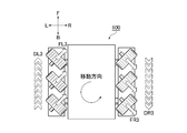
- the acting force vectors FR3 and FL3 act from the outer peripheral surface 130S of each rotating body 130 to the moving surface G.
- the acting force vector FR3 is a vector acting from the outer peripheral surface 130S of the rotating body 130 of the right drive chain 120 to the moving surface G.
- the acting force vector FL3 is a vector acting from the outer peripheral surface 130S of the rotating body 130 of the left drive chain 120 to the moving surface G.
- the rotation shaft 131 of the rotating body 130 of the right drive chain 120 is inclined 45 ° with respect to the drive direction while the right side is inclined backward and the left side is inclined forward.
- the direction of the speed vector DR3 of the right drive chain 120 is the backward direction B. Therefore, as shown in FIGS. 9A and 9B, the acting force vector FR3 is directed from the left front to the right rear while being inclined by 45 ° with respect to the driving direction.
- the rotation shaft 131 of the rotating body 130 of the left drive chain 120 is inclined 45 ° with respect to the drive direction while the right side is inclined forward and the left side is inclined backward.
- the direction of the speed vector DL3 of the left drive chain 120 is the forward direction F. Therefore, as shown in FIGS. 9A and 9B, the acting force vector FL3 is directed from the rear left to the front right while being inclined by 45 ° with respect to the driving direction.
- the direction of the component force of the acting force vector FR3 in the right and left direction and the direction of the component force of the acting force vector FL3 in the right and left direction are the same, so they are not canceled out.
- the position of the action line of the translational resultant force vector FA3S which is the sum of the rightward and leftward component force of the acting force vector FR3 and the rightward and leftward component force of the acting force vector FL3, is the center of gravity C of the multidirectional mobile module 100.
- the direction of the translational resultant force vector FA3S is rightward with respect to the multidirectional moving body module 100.
- the position of the line of action of the translational reaction force FB3S acting on the moving body module 100 from the moving surface G becomes a position passing through the center of gravity C of the multidirectional moving body module 100, and the direction of the translational reaction force FB3S is The left direction is based on the multidirectional moving body module 100.
- the component force of the action force vector FR3 in the front-rear direction and the component force of the action force vector FL3 in the front-rear direction are equal and opposite in direction, but the action line of the force component in the front-rear direction is Since the position is away from the center of gravity C of the multidirectional moving body module 100, the component force in the front-rear direction is not canceled out, and a moment (rotational force) in the clockwise direction in FIGS. 9A and 9B is generated.
- the position of the action line of the rotational resultant force vector FA3R which is the sum of the component force of the action force vector FR3 in the front-rear direction and the force component of the action force vector FL3 in the front-rear direction, is the multidirectional mobile module 100.
- the direction of the rotational resultant vector FA3R is clockwise with respect to the center of gravity C of the multidirectional moving body module 100. Accordingly, the position of the line of action of the rotational reaction force FB3R acting on the moving body module 100 from the moving surface G is away from the center of gravity C of the multidirectional moving body module 100, and the direction of the rotational reaction force FB3R is The counterclockwise direction is based on the center of gravity C of the direction moving body module 100.
- the multidirectional moving body module 100 moves to the left with respect to the moving plane G with respect to the moving surface G while rotating counterclockwise by the translational reaction force FB3S and the rotational reaction force FB3R.
- the movement is a combination of translation and rotation.
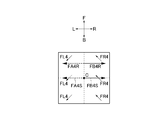
- 10A and 10B show that the speed vector DR4 of the right drive chain 120 and the speed vector DL4 of the left drive chain 120 are equal in magnitude, the direction of the speed vector DR4 is the forward direction F, and the speed This is a case where the direction of the vector DL4 is the backward direction B.
- acting force vectors FR4 and FL4 act from the outer peripheral surface 130S of each rotating body 130 to the moving surface G.
- the acting force vector FR4 is a vector that acts on the moving surface G from the outer peripheral surface 130S of the rotating body 130 of the right drive chain 120.
- the acting force vector FL4 is a vector acting from the outer peripheral surface 130S of the rotating body 130 of the left drive chain 120 to the moving surface G.
- the rotation shaft 131 of the rotating body 130 of the right drive chain 120 is inclined 45 ° with respect to the drive direction while the right side is inclined backward and the left side is inclined forward.
- the direction of the speed vector DR4 of the right drive chain 120 is the forward direction F. Accordingly, as shown in FIGS. 10A and 10B, the acting force vector FR4 is directed from the right rear to the left front in a state inclined by 45 ° with respect to the driving direction.
- the rotation shaft 131 of the rotating body 130 of the left drive chain 120 is inclined 45 ° with respect to the drive direction while the right side is inclined forward and the left side is inclined backward.
- the direction of the speed vector DL4 of the left drive chain 120 is the backward direction B. Therefore, as shown in FIGS. 10A and 10B, the acting force vector FL4 is directed from the front right to the rear left while being inclined by 45 ° with respect to the driving direction.
- the position of the action line of the translational resultant force vector FA4S which is the sum of the left and right component of the acting force vector FR4 and the right and left component of the acting force vector FL4, is the center of gravity C of the multidirectional mobile module 100.
- the direction of the translational resultant force vector FA4S is leftward with respect to the multidirectional moving body module 100.
- the position of the line of translation reaction force FB4S acting on the moving body module 100 from the moving surface G becomes a position passing through the center of gravity C of the multidirectional moving body module 100, and the direction of the translation reaction force FB4S is It turns to the right with respect to the multidirectional moving body module 100.
- the magnitude of the forward and backward component force of the acting force vector FR4 is equal to the magnitude of the backward and forward component force of the acting force vector FL4 and the directions are opposite to each other. Since the position is away from the center of gravity C of the multidirectional moving body module 100, the component force in the front-rear direction is not canceled out, and a counterclockwise force moment (rotational force) in FIGS. 10A and 10B is generated.
- the position of the action line of the rotational resultant force vector FA4R which is the sum of the component force forward of the acting force vector FR4 and the component force forward of the acting force vector FL4 in the front-and-rear direction, is the multidirectional mobile module 100.
- the direction of the rotational resultant vector FA4R is counterclockwise with respect to the center of gravity C of the multidirectional moving body module 100. Accordingly, the position of the line of action of the rotational reaction force FB4R acting on the moving body module 100 from the moving surface G is away from the center of gravity C of the multidirectional moving body module 100, and the direction of the rotational reaction force FB4R is many.
- the clockwise direction is based on the center of gravity C of the direction moving body module 100.
- the multidirectional moving body module 100 moves to the right with respect to the moving plane G with respect to the moving plane G while rotating clockwise by the translational reaction force FB4S and the rotational reaction force FB4R.
- the movement is a combination of translation and rotation.
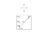
- FIG. 11A and FIG. 11B show that the speed vector DL5 of the right drive chain 120 which is one of the pair is zero, and the speed vector DL5 of the left drive chain 120 which is the other is zero. This is the case when the direction is larger and the direction is the backward direction B. In this case, the acting force vector FL5 acts from the outer peripheral surface 130S of the rotating body 130 of the left drive chain 120 to the moving surface G.
- the rotation shaft 131 of the rotating body 130 of the left drive chain 120 is inclined 45 ° with respect to the drive direction while the right side is inclined forward and the left side is inclined backward.
- the direction of the speed vector DL5 of the left drive chain 120 is the backward direction B. Accordingly, as shown in FIGS. 11A and 11B, the acting force vector FL5 is directed from the right front to the left rear in a state inclined by 45 ° with respect to the driving direction.
- the rotation shaft 131 of the rotating body 130 of the right drive chain 120 is inclined at 45 ° with respect to the drive direction while the right side is inclined backward and the left side is inclined forward.
- the rotating body 130 provided on the right drive chain 120 acts so as to release the acting force vector FL5.
- the direction of the resultant force vector FA5 that is the sum of the respective acting force vectors FL5 is the same as the acting force vector FL5. In other words, the direction is from front right to rear left with a 45 ° tilt with respect to the driving direction.
- the center of gravity C of the multidirectional moving body module 100 When the center of gravity C of the multidirectional moving body module 100 is located on the action line of the resultant vector FA5, the direction of the reaction force FB5 acting on the moving body module 100 from the moving surface G is inclined by 45 ° with respect to the driving direction. The direction is from left rear to right front. Furthermore, the center of gravity C of the multidirectional moving body module 100 is also located on the line of action of the reaction force FB5. That is, no moment of force (rotational force) is generated. For this reason, the multidirectional moving body module 100 moves (translates) in the direction of 45 ° diagonally right frontward.
- the direction of the reaction force FB5 is tilted by 45 ° with respect to the driving direction from left rear to right front.
- the position of the action line of the reaction force FB5 is also away from the center of gravity C of the multidirectional moving body module 100. That is, a moment of force (rotational force) is generated. Since the rotational motion and the translation motion are combined, the multidirectional moving body module 100 moves while bending in a predetermined direction.
- the multidirectional moving body module 100 bends clockwise while proceeding diagonally forward to the right.
- the multidirectional mobile module 100 bends counterclockwise while proceeding diagonally forward to the right.
- 12A and 12B show that the speed vector DR6 of the right drive chain 120 as one of the pair is larger than zero and smaller than the speed vector DL6 of the left drive chain 120 as the other.
- the direction of the velocity vector DR6 is the forward direction F
- the direction of the velocity vector DL6 is the backward direction B.
- the acting force vectors FR6 and FL6 act from the outer peripheral surface 130S of each rotating body 130 to the moving surface G.
- the acting force vector FR6 is a vector that acts on the moving surface G from the outer peripheral surface 130S of the rotating body 130 of the right drive chain 120.
- the acting force vector FL6 is a vector that acts on the moving surface G from the outer peripheral surface 130S of the rotating body 130 of the left drive chain 120.
- the rotation shaft 131 of the rotating body 130 of the right drive chain 120 is inclined 45 ° with respect to the drive direction while the right side is inclined backward and the left side is inclined forward.
- the direction of the speed vector DR6 of the right drive chain 120 is the forward direction F. Therefore, as shown in FIGS. 12A and 12B, the acting force vector FR6 is directed from the right rear to the left front in a state inclined by 45 ° with respect to the driving direction.
- the rotation shaft 131 of the rotating body 130 of the left drive chain 120 is inclined 45 ° with respect to the drive direction while the right side is inclined forward and the left side is inclined backward.
- the direction of the speed vector DL6 of the left drive chain 120 is the backward direction B. Accordingly, as shown in FIGS. 12A and 12B, the acting force vector FL6 is directed from the right front to the left rear while being inclined by 45 ° with respect to the driving direction.
- the position of the action line of the translational resultant force vector FA6S which is the sum of the left and right component of the acting force vector FR6 and the right and left component of the acting force vector FL6, is the center of gravity C of the multidirectional mobile module 100.
- the direction of the translational resultant force vector FA6S is leftward with respect to the multidirectional moving body module 100.
- the position of the action line of the translational reaction force FB6S acting on the moving body module 100 from the moving surface G becomes a position passing through the center of gravity C of the multidirectional moving body module 100, and the direction of the translational reaction force FB6S is It turns to the right with respect to the multidirectional moving body module 100.
- the position of the action line of the rotational resultant force vector FA6R which is the sum of the forward and backward component forces of the acting force vector FR6 and the backward and forward force components of the acting force vector FL6, is the multidirectional mobile module 100.
- the direction of the rotational resultant vector FA6R is counterclockwise with reference to the center of gravity C of the multidirectional moving body module 100.
- the position of the action line of the rotational reaction force FB6R acting on the moving body module 100 from the moving surface G is away from the center of gravity C of the multidirectional moving body module 100, and the direction of the rotational reaction force FB6R is many.
- the clockwise direction is based on the center of gravity C of the direction moving body module 100.
- the multidirectional moving body module 100 moves to the right with respect to the moving plane G with respect to the moving plane G while rotating clockwise by the translational reaction force FB6S and the rotational reaction force FB6R.
- the acting force vector FL6 is the same as the magnitude of the backward force in the front-rear direction of the acting force vector FL4 in the case shown in FIGS. 10A and 10B, the acting force vector The magnitude of the forward force in the front-rear direction of FR6 is smaller than the magnitude of the forward force in the front-rear direction of the acting force vector FR4 in the case shown in FIGS. 10A and 10B.
- the magnitude of the rotational reaction force FB6R shown in FIGS. 12A and 12B is smaller than the magnitude of the rotational reaction force FB4R shown in FIGS. 10A and 10B.
- the left side of the multi-directional moving body module 100 moves backward with the right side as a fulcrum. Try to move forward more than the right travel distance. That is, the multidirectional moving body module 100 bends clockwise while proceeding diagonally forward to the right.
- FIG. 13A and FIG. 13B show that the speed vector DR7 of the right drive chain 120 which is one of the pair is larger than zero and smaller than the speed vector DL7 which is the other left side. Is the backward direction B, and the direction of the velocity vector DL7 is the backward direction B.
- the acting force vectors FR7 and FL7 act from the outer peripheral surface 130S of each rotating body 130 to the moving surface G.
- the acting force vector FR7 is a vector acting from the outer peripheral surface 130S of the rotating body 130 of the right drive chain 120 to the moving surface G.
- the acting force vector FL7 is a vector that acts on the moving surface G from the outer peripheral surface 130S of the rotating body 130 of the left drive chain 120.
- the rotation shaft 131 of the rotating body 130 of the right drive chain 120 is inclined 45 ° with respect to the drive direction while the right side is inclined backward and the left side is inclined forward.
- the direction of the speed vector DR7 of the right drive chain 120 is the backward direction B. Therefore, as shown in FIGS. 13A and 13B, the acting force vector FR7 is directed from the left front to the right rear while being inclined by 45 ° with respect to the driving direction.
- the rotation shaft 131 of the rotating body 130 of the left drive chain 120 is inclined 45 ° with respect to the drive direction while the right side is inclined forward and the left side is inclined backward.
- the direction of the speed vector DL7 of the left drive chain 120 is the backward direction B. Accordingly, as shown in FIGS. 13A and 13B, the acting force vector FL7 is directed from the right front to the left rear while being inclined by 45 ° with respect to the driving direction.
- the magnitudes of the rightward and leftward component forces of the acting force vector FR7 and the leftward and rightward component forces of the acting force vector FL7 are not equal, the directions are opposite to each other and are on the same line.
- the left-right component of force vector FL7 is reduced by the right-left component of action vector FR7.
- the position of the action line of the left-right translational resultant force vector which is the sum of the left-right component of the acting force vector FR7 and the right-left component of the acting force vector FL7, is the center of gravity of the multidirectional mobile module 100.
- the direction of the translational force vector in the left-right direction is leftward with respect to the multidirectional moving body module 100.
- the direction of the force component FR7 in the front-rear direction and the component force in the front-rear direction of the force vector FL7 are the same, but the magnitudes are not equal to each other, and the action of the force component in the front-rear direction Since the position of the line is away from the center of gravity C of the multidirectional moving body module 100 but is in a laterally symmetrical positional relationship, the longitudinal translational resultant force vector that translates backward in the longitudinal direction and the counterclockwise rotation in FIGS. 13A and 13B A moment of force (rotational force) is generated.
- the translational force vector in the front-rear direction includes a component force that acts backward in the front-rear direction of the acting force vector FR7, and a component force that acts backward in the front-rear direction of the acting force vector FR7 among the component forces in the rearward direction in the acting force vector FL7. It is the sum of the same size.
- the magnitude of the resultant rotational force vector FA7R which is a moment of force (rotational force) is the difference between the magnitude of the backward force in the front-rear direction of the action force vector FL7 and the magnitude of the force in the rearward direction of the action force vector FR7. It is. Further, the position of the line of action of the rotational resultant vector FA7R is away from the center of gravity C of the multidirectional moving body module 100, and the direction of the rotational resultant vector FA7R is counterclockwise with respect to the center of gravity C of the multidirectional moving body module 100. It becomes the turning direction.
- the position of the line of action of the rotational reaction force FB7R acting on the moving body module 100 from the moving surface G is away from the center of gravity C of the multidirectional moving body module 100, and the direction of the rotational reaction force FB7R is many.
- the clockwise direction is based on the center of gravity C of the direction moving body module 100.
- the position of the action line of the translational resultant force vector FA7S which is the sum of the lateral translational force vector and the longitudinal translational force vector, becomes a position passing through the center of gravity C of the multidirectional mobile module 100, and the translational resultant force vector FA7S.
- the direction is a diagonally backward left direction with respect to the multi-directional moving body module 100. Accordingly, the position of the action line of the translation reaction force FB7S acting on the moving body module 100 from the moving surface G becomes a position passing through the center of gravity C of the multidirectional moving body module 100, and the direction of the translation reaction force FB7S is It becomes the diagonally forward right direction with respect to the multidirectional moving body module 100.
- the multi-directional moving body module 100 moves to the right front side with respect to the moving plane G with respect to the moving surface G while rotating clockwise by the translational reaction force FB7S and the rotational reaction force FB7R. . That is, the multidirectional moving body module 100 bends in a clockwise direction while proceeding diagonally forward to the right, which is largely closer to the front than in the case illustrated in FIG. 12A.
- the multi-directional moving body module 100 of the present embodiment obtained in this way includes a moving body module main body 110 that moves on the moving surface G, and a driving module provided at the front and rear of each of the left and right sides of the moving body module main body 110.
- a fixed pedestal portion 140A which is a block body for restricting chain bending, in which the opposing end surfaces 141AS and 141AS can be brought into contact with each other in accordance with a change in the posture of the drive chain 120.
- the drive shaft 120 is inclined at a predetermined angle with respect to the drive direction of the drive chain 120, and the tilt of the rotary shaft 131 of the rotary body 130 is determined by the pair of left and right drive chains 120, 120 in the front-rear direction of the mobile module main body 110.
- the attitude of the drive chain 120 is bent along the outer circumferences of the drive sprocket 111 and the driven member 112
- the fixed base portion 140A is adjacent to each other in the longitudinal direction of the chain.
- the end surfaces 141AS and 141AS are separated from each other in the longitudinal direction of the chain, and the posture of the drive chain 120 is the chain.
- the multidirectional moving body module of the present modification is different only in that the wall-like block body 140B is used in place of the fixing base portion 140A as the above-described chain bending restriction block body. Parts common to the mobile module 100 are denoted by common reference numerals, and detailed description thereof is omitted.
- the chain longitudinal direction outer side surface 142BS of the pair of wall-like block bodies 140B and 140B installed on the side of the rotating body 130 used in the multidirectional moving body module of the present modification is It is formed closer to the inner periphery of the drive chain 120 than the contact line 130L that contacts the moving surface G on the outer peripheral surface 130S of the rotating body 130.
- the location where the bending of the drive chain 120 is restricted is the side of the rotating body 130 where the lever ratio becomes small far from the so-called chain bending fulcrum.
- the chain bending restricting block body is composed of a pair of wall-like block bodies 140B and 140B installed on the side of the rotating body 130.
- the chain longitudinal direction outer side surface 142BS of the wall-shaped block body 140B is formed closer to the inner periphery of the drive chain 120 than the contact line 130L contacting the moving surface G of the outer peripheral surface 130S of the rotating body 130.
- Multi-directional moving body module 110 ... Moving body module main body 111, 111RF, 111LB ... Drive sprocket 112, 112RB, 112LF ... Driven member 113F, 113B ... Drive motor 114RF, 1414LB .... Drive shafts 114RB, 114LF ... Driven shaft 120 ... Drive chain 130 ... Rotating body 130L ... Contact line in contact with the moving surface 130S ... Outer peripheral surface of the rotating body 131 ...
Landscapes
- Engineering & Computer Science (AREA)
- Chemical & Material Sciences (AREA)
- Combustion & Propulsion (AREA)
- Transportation (AREA)
- Mechanical Engineering (AREA)
- Toys (AREA)
Description
本発明は、搭乗者の移動手段や被搬送物を搬送する搬送手段に応用される移動機構に関するものであって、特に、駆動力を得て円滑に移動及び転回する多方向移動体モジュールに関する。
従来、回転体の操舵により移動方向を変更する移動機構として、左右一対の前輪及び後輪を備えて前輪等の操舵により車体の向きを転回して車両の移動方向を変更する車両がごく普通に知られている。
そして、車両などの移動体に左右一対で設けられた無限軌道によって移動体を移動させる方法やホイール体に設けられたローラ体によって移動方向を変更するものであって、2つの支持部材を有するホイール体を備え、これら支持部材の間に少なくとも部分的に支持部材の円周から突き出した状態で配置された多数のローラ体の回転軸がホイール体の回転軸に対して斜めに向いているホイールいわゆるメカナムホイールを備えた車両がある(例えば、特許文献1参照。)。
また、中心本体と無端形状を有するローラユニットとローラユニットに係合して中心本体に対してローラユニットであるチェーンを駆動する駆動手段とを備えているローラ駆動要素がある(例えば、特許文献2参照。)。
そして、車両などの移動体に左右一対で設けられた無限軌道によって移動体を移動させる方法やホイール体に設けられたローラ体によって移動方向を変更するものであって、2つの支持部材を有するホイール体を備え、これら支持部材の間に少なくとも部分的に支持部材の円周から突き出した状態で配置された多数のローラ体の回転軸がホイール体の回転軸に対して斜めに向いているホイールいわゆるメカナムホイールを備えた車両がある(例えば、特許文献1参照。)。
また、中心本体と無端形状を有するローラユニットとローラユニットに係合して中心本体に対してローラユニットであるチェーンを駆動する駆動手段とを備えているローラ駆動要素がある(例えば、特許文献2参照。)。
しかしながら、移動面上に静止させた通常の車両を転回させる場合、前輪だけでなく後輪を含めた4つの駆動輪を操舵する機構を設けることになるため、駆動輪の操舵機構が複雑化するという問題点があった。
また、上述した特許文献1のようなホイールでは、移動面に接地した一つのローラ体の駆動軸に荷重が集中してしまうため、ローラ体に対する荷重負担が大きくなるという問題点があった。
加えて、上述したホイールでは、複数のローラ体の一つのみを走行面である移動面に常時接触させた状態で移動体本体の駆動力を得ているため、複数のローラ体を移動面に接触させて移動体本体を駆動する場合に比べて駆動力を得られ難いという問題点があった。
上述のホイールにおいて、ローラ体を軸支する駆動軸径を大きくすることで軸強度を高めて移動体本体の荷重を支えた場合、ローラ体の駆動軸径のサイズ増大に伴って接地面である移動面に対する移動体の重心が高くなるため、移動体の移動機構が不安定になるという問題点があった。
また、上述した特許文献1のようなホイールでは、移動面に接地した一つのローラ体の駆動軸に荷重が集中してしまうため、ローラ体に対する荷重負担が大きくなるという問題点があった。
加えて、上述したホイールでは、複数のローラ体の一つのみを走行面である移動面に常時接触させた状態で移動体本体の駆動力を得ているため、複数のローラ体を移動面に接触させて移動体本体を駆動する場合に比べて駆動力を得られ難いという問題点があった。
上述のホイールにおいて、ローラ体を軸支する駆動軸径を大きくすることで軸強度を高めて移動体本体の荷重を支えた場合、ローラ体の駆動軸径のサイズ増大に伴って接地面である移動面に対する移動体の重心が高くなるため、移動体の移動機構が不安定になるという問題点があった。
また、上述した特許文献2のような無端形状を構成するローラユニットであるチェーンを備えたローラ駆動要素では、チェーンのうち移動面側である移動体の接地面側に繰り出されて直線状に駆動されるべきチェーン部分が移動面から応力を受けるため、移動面側に繰り出されたチェーン部分が容易に撓むとともに接地面に対するチェーンの接触部分に摩耗が生じ易くなってチェーンの寿命が低下するという問題点があった。
そして、上述のチェーン部分の撓みを防ぐためにチェーンに過剰な張力を加えて直線状に維持した場合、チェーンに過剰な張力を付与し続ける複雑な張力付与機構を設けることになるため、部品点数及び部品コストが増加するとともに省スペース化が困難になるという問題点があった。
そして、上述のチェーン部分の撓みを防ぐためにチェーンに過剰な張力を加えて直線状に維持した場合、チェーンに過剰な張力を付与し続ける複雑な張力付与機構を設けることになるため、部品点数及び部品コストが増加するとともに省スペース化が困難になるという問題点があった。
そこで、本発明が解決しようとする技術的課題、すなわち、本発明の目的は、操舵機構の複雑化と移動機構の重心が高くなることと移動面側に繰り出されたチェーン部分の撓みとチェーン寿命の低下とを防ぐとともに回転体の荷重負担を軽減し、部品点数の削減と省スペース化を実現し、十分な駆動力を得て円滑に移動及び転回する多方向移動体モジュールを提供することである。
本請求項1に係る発明は、移動面上を移動する移動体モジュール本体と、該移動体モジュール本体の左右それぞれで前後に設けられた駆動用スプロケットおよび従動部材と、前記左右のそれぞれの駆動用スプロケットおよび従動部材に巻き掛けられた状態で左右独立して進退自在に駆動される一対の駆動チェーンと、前記駆動チェーンの外周側で駆動チェーンの駆動方向に沿って回転自在に配設され、回転軸を有して移動面に外周面をそれぞれ接触させる複数の回転体と、前記駆動チェーンの外周側に配列された状態でそれぞれ固定されて駆動チェーンの姿勢の変化に応じて対向端面同士を当接自在な複数のチェーン屈曲規制用ブロック体とを備え、前記回転体の回転軸が、前記駆動チェーンの駆動方向に対してそれぞれ所定の角度で傾いているとともに、前記回転体の回転軸の傾きが、前記左右の一対の駆動チェーンで移動体モジュール本体での前後方向の線を基準とした線対称の関係を有し、前記駆動チェーンの姿勢が駆動用スプロケットおよび従動部材の外周に沿って曲がったとき、前記チェーン屈曲規制用ブロック体のチェーン長手方向で隣り合う対向端面同士が、前記チェーン長手方向で互いに離間し、前記駆動チェーンの姿勢がチェーン長手方向に直線状になったとき、前記チェーン屈曲規制用ブロック体のチェーン長手方向で隣り合う対向端面同士が、前記チェーン長手方向で互いに当接する構成であることにより、前述した課題を解決したものである。
本請求項2に係る発明は、請求項1に記載された多方向移動体モジュールの構成に加えて、前記チェーン屈曲規制用ブロック体が、前記回転体の側方に設置された一対の壁状ブロック体から構成されているとともに、該壁状ブロック体の外側側面が、前記回転体の外周面での移動面に接触する接触線より前記駆動チェーンの内周寄りに形成されていることにより、前述した課題をさらに解決したものである。
本請求項3に係る発明は、請求項1に記載された多方向移動体モジュールの構成に加えて、前記チェーン屈曲規制用ブロック体が、前記回転体を駆動チェーンに固定する固定用台座部であることにより、前述した課題をさらに解決したものである。
本請求項4に係る発明は、請求項1に記載された多方向移動体モジュールの構成に加えて、前記一対の駆動チェーンのそれぞれの駆動方向が、相互に平行な関係であることにより、前述した課題をさらに解決したものである。
本請求項5に係る発明は、請求項1に記載された多方向移動体モジュールの構成に加えて、前記一対の駆動チェーンの一方に設けられた回転体の回転軸線と前記一対の駆動チェーンの他方に設けられた回転体の回転軸線とが、前記駆動チェーンの駆動方向に対してそれぞれ45°傾いていることにより、前述した課題をさらに解決したものである。
本発明の多方向移動体モジュールは、移動面上を移動する移動体モジュール本体と、この移動体モジュール本体の左右それぞれで前後に設けられた駆動用スプロケットおよび従動部材と、左右のそれぞれの駆動用スプロケットおよび従動部材に巻き掛けられた状態で左右独立して進退自在に駆動される一対の駆動チェーンと、駆動チェーンの外周側で駆動チェーンの駆動方向に沿って回転自在に配設され、回転軸を有して移動面に外周面をそれぞれ接触させる複数の回転体とを備え、回転体の回転軸が、駆動チェーンの駆動方向に対してそれぞれ所定の角度で傾いているとともに、回転体の回転軸の傾きが、左右の一対の駆動チェーンで移動体モジュール本体での前後方向の線を基準とした線対称の関係を有していることにより、左右方向の分力を相殺して前後方向へ移動したり、左右方向の分力を減殺または増加させてさまざまな方向へ移動したり、力の作用線上を多方向移動体モジュールの重心に対してずらして回転モーメントを発生させて回転することができるばかりでなく、以下のような特有の効果を奏することができる。
本発明の請求項1に係る発明の多方向移動体モジュールによれば、駆動チェーンの外周側に配列された状態でそれぞれ固定されて駆動チェーンの姿勢の変化に応じて対向端面同士を当接自在な複数のチェーン屈曲規制用ブロック体を備え、駆動チェーンの姿勢が駆動用スプロケットおよび従動部材の外周に沿って曲がったとき、チェーン屈曲規制用ブロック体のチェーン長手方向で隣り合う対向端面同士が、チェーン長手方向で互いに離間し、駆動チェーンの姿勢がチェーン長手方向に直線状になったとき、チェーン屈曲規制用ブロック体のチェーン長手方向で隣り合う対向端面同士が、チェーン長手方向で互いに当接する構成であることにより、駆動チェーンのうち移動面側に繰り出されたチェーン部分が直線状となって1つのチェーン屈曲規制用ブロック体がチェーン長手方向で隣のチェーン屈曲規制用ブロック体と当接してこの繰り出されたチェーン部分での駆動用スプロケットおよび従動部材の外周に沿う側と反対側への曲がりが規制されるため、移動面側に繰り出されたチェーン部分の無端形状の外周から内周に向かう撓みを防止できる。
さらに、移動面側に繰り出されたチェーン部分が直線状となるため、移動面に対して十分に駆動力を伝達できる。
また、駆動チェーンの摩耗が抑制され、しかも移動面に常時複数の回転体が接触して荷重全体を支持することで荷重が分散されて回転体一個当りの荷重負担が小さくなるため、操舵機構の複雑化と移動機構の高くなりがちな重心とチェーン寿命の低下とを防止できる。
さらに、回転体の荷重負担の軽減と部品点数の削減と省スペース化とを実現し、十分な駆動力を得て円滑に移動及び転回することができる。
また、駆動チェーンの摩耗が抑制され、しかも移動面に常時複数の回転体が接触して荷重全体を支持することで荷重が分散されて回転体一個当りの荷重負担が小さくなるため、操舵機構の複雑化と移動機構の高くなりがちな重心とチェーン寿命の低下とを防止できる。
さらに、回転体の荷重負担の軽減と部品点数の削減と省スペース化とを実現し、十分な駆動力を得て円滑に移動及び転回することができる。
本請求項2に係る発明の多方向移動体モジュールによれば、請求項1に係る発明が奏する効果に加えて、チェーン屈曲規制用ブロック体が、回転体の側方に設置された一対の壁状ブロック体から構成されているとともに、この壁状ブロック体でのチェーン長手方向外側側面が、回転体の外周面での移動面に接触する接触線より駆動チェーンの内周寄りに形成されていることにより、駆動チェーンの屈曲を規制する箇所が所謂、チェーン屈曲支点から遠方でてこ比の小さくなる回転体の側方となるため、回転体と移動面との相互接触を確実に維持できる。
本請求項3に係る発明の多方向移動体モジュールによれば、請求項1に係る発明が奏する効果に加えて、チェーン屈曲規制用ブロック体が回転体を駆動チェーンに固定する固定用台座部であることにより、回転体の交換時に固定用台座部ごと交換自在となるため、メンテナンスのコストを削減することができる。
本請求項4に係る発明の多方向移動体モジュールによれば、請求項1に係る発明が奏する効果に加えて、一対の駆動チェーンのそれぞれの駆動方向が相互に平行な関係であることにより、一対の駆動チェーンの駆動速度を制御して移動体モジュール本体の移動速度及びその方向について調整自在となるため、簡便な駆動制御システム及び方法により十分な駆動力を得て多方向に円滑、かつ、自在に移動及び転回することができる。
本請求項5に係る発明の多方向移動体モジュールによれば、請求項1に係る発明が奏する効果に加えて、一対の駆動チェーンの一方に設けられた回転体の回転軸線と一対の駆動チェーンの他方に設けられた回転体の回転軸線とが駆動チェーンの駆動方向に対してそれぞれ45°傾いていることにより、効率よく前後方向の分力と左右方向の分力とに分かれるため、各回転軸を無秩序に駆動方向に斜交させている場合に比べて前後方向及び左右方向を含む全ての方向に均等に移動トルクを得ることができる。
本発明の多方向移動体モジュールは、移動面上を移動する移動体モジュール本体と、この移動体モジュール本体の左右それぞれで前後に設けられた駆動用スプロケットおよび従動部材と、左右のそれぞれの駆動用スプロケットおよび従動部材に巻き掛けられた状態で左右独立して進退自在に駆動される一対の駆動チェーンと、駆動チェーンの外周側で駆動チェーンの駆動方向に沿って回転自在に配設され、回転軸を有して移動面に外周面をそれぞれ接触させる複数の回転体と、駆動チェーンの外周側に配列された状態でそれぞれ固定されて駆動チェーンの姿勢の変化に応じて対向端面同士を当接自在な複数のチェーン屈曲規制用ブロック体とを備え、回転体の回転軸が、駆動チェーンの駆動方向に対してそれぞれ所定の角度で傾いているとともに、回転体の回転軸の傾きが、左右の一対の駆動チェーンで移動体モジュール本体での前後方向の線を基準とした線対称の関係を有し、駆動チェーンの姿勢が駆動用スプロケットおよび従動部材の外周に沿って曲がったとき、チェーン屈曲規制用ブロック体のチェーン長手方向で隣り合う対向端面同士が、チェーン長手方向で互いに離間し、駆動チェーンの姿勢がチェーン長手方向に直線状になったとき、チェーン屈曲規制用ブロック体のチェーン長手方向で隣り合う対向端面同士が、チェーン長手方向で互いに当接する構成であり、操舵機構の複雑化と移動機構の高くなりがちな重心と移動面側に繰り出されたチェーン部分の撓みとチェーン寿命の低下とを同時に防ぐとともに回転体の荷重負担の軽減と部品点数の削減と省スペース化とを実現し、十分な駆動力を得て円滑に移動及び転回するものであれば、その具体的な実施の態様は如何なるものであっても何ら構わない。
本発明における「複数の回転体の配列ピッチに対応するピッチ」は、複数の回転体の配列ピッチと同様に規則的な間隔という意味である。
これは、複数の回転体の配列ピッチと等しい場合に限定されず、複数の回転体の配列ピッチの整数倍ピッチでもよいし、1/2ピッチでもよい。
本発明における「回転体の側方」は、駆動チェーンの幅方向に沿って回転体の少なくとも一方の側を意味する。
そして、本発明で用いる複数の回転体は、複数の回転体のうち駆動チェーンの駆動方向に沿って少なくとも相互に隣り合う2つの回転体を一組として、この組を一定の間隔で周期的に配列させた状態を実現するように配列されていてもよい。
また、一対の駆動チェーンのそれぞれに配列された回転体を駆動チェーンの駆動方向に沿って左右互い違いに配列させて全体として千鳥状の配列状態を実現するように配列されていてもよい。
また、本発明で用いる一対の駆動チェーンは、駆動チェーンの駆動方向に複数設けられていてもよいし、駆動チェーンの幅方向に複数設けられていてもよい。
さらに、本発明で用いる従動部材は、駆動チェーンを駆動する駆動用スプロケットと同様の形状を有する従動用スプロケットでもよいし、外周面に駆動チェーンを掛け回した状態で駆動チェーンの駆動に従動回転する円筒状部材であってもよい。
これは、複数の回転体の配列ピッチと等しい場合に限定されず、複数の回転体の配列ピッチの整数倍ピッチでもよいし、1/2ピッチでもよい。
本発明における「回転体の側方」は、駆動チェーンの幅方向に沿って回転体の少なくとも一方の側を意味する。
そして、本発明で用いる複数の回転体は、複数の回転体のうち駆動チェーンの駆動方向に沿って少なくとも相互に隣り合う2つの回転体を一組として、この組を一定の間隔で周期的に配列させた状態を実現するように配列されていてもよい。
また、一対の駆動チェーンのそれぞれに配列された回転体を駆動チェーンの駆動方向に沿って左右互い違いに配列させて全体として千鳥状の配列状態を実現するように配列されていてもよい。
また、本発明で用いる一対の駆動チェーンは、駆動チェーンの駆動方向に複数設けられていてもよいし、駆動チェーンの幅方向に複数設けられていてもよい。
さらに、本発明で用いる従動部材は、駆動チェーンを駆動する駆動用スプロケットと同様の形状を有する従動用スプロケットでもよいし、外周面に駆動チェーンを掛け回した状態で駆動チェーンの駆動に従動回転する円筒状部材であってもよい。
以下、本発明の実施例に係る多方向移動体モジュール100及びその変形例を図1乃至図16に基づいて説明する。
なお、本実施形態において、駆動チェーン120を正方向に駆動するとは、駆動チェーン120の接地面側部分である移動面側部分である下側部分を後退方向Bに駆動するとともに駆動チェーン120の上側部分を前進方向Fに駆動するように駆動チェーン120全体を駆動することをいう。
また、駆動チェーン120を逆方向に駆動するとは、上述の正方向に対して逆向きに駆動チェーン120全体を駆動することをいう。
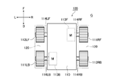
図5では、移動体モジュール本体110の前後に設けられた駆動用スプロケット111及び従動部材112を前後で区別するために、右側の前後に設けられた駆動用スプロケット111及び従動部材112を、駆動用スプロケット111RF及び従動部材112RBとする。
同様に、左側の前後に設けられた従動部材112及び駆動用スプロケット111を、従動部材112LF及び駆動用スプロケット111LBとして参照符号を付け替えている。
また、駆動チェーン120を逆方向に駆動するとは、上述の正方向に対して逆向きに駆動チェーン120全体を駆動することをいう。
図5では、移動体モジュール本体110の前後に設けられた駆動用スプロケット111及び従動部材112を前後で区別するために、右側の前後に設けられた駆動用スプロケット111及び従動部材112を、駆動用スプロケット111RF及び従動部材112RBとする。
同様に、左側の前後に設けられた従動部材112及び駆動用スプロケット111を、従動部材112LF及び駆動用スプロケット111LBとして参照符号を付け替えている。
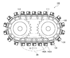
図1乃至図6を参照しながら、本実施例の多方向移動体モジュール100の構成を説明する。
図1乃至図6に示すように、多方向移動体モジュール100は、移動面G上を移動する移動体モジュール本体110と、この移動体モジュール本体110の左右それぞれで前後に設けられた駆動用スプロケット111RF、111LBおよび従動部材112RB、112LFとを備えている。
このうち、駆動用スプロケット111RFは、右側の前側に配設されており、駆動用スプロケット111LBは、左側の後側に配設されている。
また、従動部材112RBは、右側の後側に配設されており、従動部材112LFは、左側の前側に配設されている。
図1乃至図6に示すように、多方向移動体モジュール100は、移動面G上を移動する移動体モジュール本体110と、この移動体モジュール本体110の左右それぞれで前後に設けられた駆動用スプロケット111RF、111LBおよび従動部材112RB、112LFとを備えている。
このうち、駆動用スプロケット111RFは、右側の前側に配設されており、駆動用スプロケット111LBは、左側の後側に配設されている。
また、従動部材112RBは、右側の後側に配設されており、従動部材112LFは、左側の前側に配設されている。
さらに、駆動用スプロケット111RFおよび従動部材112RBと、駆動用スプロケット111LBおよび従動部材112LFとのそれぞれに巻き掛けられた状態で左右独立して進退自在に駆動される一対の駆動チェーン120、120と、駆動チェーン120の外周側で駆動チェーン120の駆動方向に沿って回転自在に配設され、回転軸131を有して移動面Gに外周面130Sをそれぞれ接触させる複数の回転体130と、駆動チェーン120の外周側に配列された状態でそれぞれ固定されて駆動チェーン120の姿勢の変化に応じて対向端面141AS、141AS同士を当接自在な複数のチェーン屈曲規制用ブロック体の一例である固定用台座部140Aとを備えている。
また、回転体130の回転軸131が、駆動チェーン120の駆動方向に対してそれぞれ所定の角度で傾いているとともに、回転体130の回転軸131の傾きが、左右の一対の駆動チェーン120で移動体モジュール本体110での前後方向の線を基準とした線対称の関係を有している。
これにより、詳しくは後述するように、左右方向の分力を相殺して前後方向へ移動したり、左右方向の分力を減殺または増加させてさまざまな方向へ移動したり、力の作用線上を多方向移動体モジュール100の重心Cに対してずらして回転モーメントを発生させて回転することができる。
これにより、詳しくは後述するように、左右方向の分力を相殺して前後方向へ移動したり、左右方向の分力を減殺または増加させてさまざまな方向へ移動したり、力の作用線上を多方向移動体モジュール100の重心Cに対してずらして回転モーメントを発生させて回転することができる。
さらに、駆動チェーン120の姿勢が駆動用スプロケット111および従動部材112の外周に沿って曲がったとき、チェーン屈曲規制用ブロック体としての固定用台座部140Aのチェーン長手方向で隣り合う対向端面141AS、141AS同士が、前記チェーン長手方向で互いに離間し、駆動チェーン120の姿勢がチェーン長手方向に直線状になったとき、固定用台座部140Aのチェーン長手方向で隣り合う対向端面141AS、141AS同士が、前記チェーン長手方向で互いに当接する構成である。
これにより、駆動チェーン120のうち移動面G側に繰り出されたチェーン部分が直線状となって1つの固定用台座部140Aがチェーン長手方向で隣の固定用台座部140Aと当接してこの繰り出されたチェーン部分での駆動用スプロケット111および従動部材112の外周に沿う側と反対側への曲がりが規制される。
つまり、移動面G側に繰り出されたチェーン部分の無端形状の外周から内周に向かう撓み(図3中仮想線で示す無端形状の外周から内周に向かう撓み)が規制される。
さらに、駆動チェーン120の摩耗が抑制され、しかも移動面Gに常時複数の回転体130が接触して荷重全体を支持することで荷重が分散されて回転体一個当りの荷重負担が小さくなる。
つまり、移動面G側に繰り出されたチェーン部分の無端形状の外周から内周に向かう撓み(図3中仮想線で示す無端形状の外周から内周に向かう撓み)が規制される。
さらに、駆動チェーン120の摩耗が抑制され、しかも移動面Gに常時複数の回転体130が接触して荷重全体を支持することで荷重が分散されて回転体一個当りの荷重負担が小さくなる。
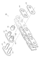
なお、図2に示すように、駆動チェーン120は、左右一対の内プレート121に前後一対のブシュ124を圧入嵌合してなる内リンクユニットと、この内リンクユニットの外側に配置された外プレート122と、この外プレート122に圧入嵌合して内リンクユニット及び外プレート122をチェーン長手方向に多数連結する複数の連結ピン123と、ブシュ124を遊嵌したローラ125とを備えて構成されている。
駆動チェーン120は、ローラ125を設けない場合であってもその動作に何ら支障はない。
駆動チェーン120は、ローラ125を設けない場合であってもその動作に何ら支障はない。
図5に示すように、駆動軸114RF及び駆動軸114LBは、相互に繋がっていない状態で駆動チェーン120を独立して駆動するように構成されている。
同様に、従動軸114LF及び従動軸114RBも、相互に繋がっていない。
駆動モータ113Fは、駆動用スプロケット111RFを駆動させる。
すると、駆動チェーン120によって動力が伝達されて、従動部材112RBが、駆動用スプロケット111RFの駆動に応じて従動回転する。
同様に、駆動モータ113Bは、駆動用スプロケット111LBを駆動させる。
すると、駆動チェーン120によって動力が伝達されて、従動部材112LFが、駆動用スプロケット111LBの駆動に応じて従動回転する。
つまり、図中左右に配置された駆動チェーン120、120は、相互に独立して駆動される。
同様に、従動軸114LF及び従動軸114RBも、相互に繋がっていない。
駆動モータ113Fは、駆動用スプロケット111RFを駆動させる。
すると、駆動チェーン120によって動力が伝達されて、従動部材112RBが、駆動用スプロケット111RFの駆動に応じて従動回転する。
同様に、駆動モータ113Bは、駆動用スプロケット111LBを駆動させる。
すると、駆動チェーン120によって動力が伝達されて、従動部材112LFが、駆動用スプロケット111LBの駆動に応じて従動回転する。
つまり、図中左右に配置された駆動チェーン120、120は、相互に独立して駆動される。
図5に示すように、前後のそれぞれに一つずつ駆動モータ113F、113Bを配置することにより、多方向駆動体モジュール100の重量バランスをとることと、モータの設置スペースを確保することとの両方を実現している。
図1乃至図4に示すように、多方向移動体モジュール100に用いる回転体130を駆動チェーン120に固定する固定用台座部140Aは、チェーン屈曲規制用ブロック体の一例である。
これにより、回転体130の交換時に固定用台座部140Aごと交換自在となる。
つまり、多方向移動体モジュール100は、メンテナンスのコストを削減するように構成されている。
これにより、回転体130の交換時に固定用台座部140Aごと交換自在となる。
つまり、多方向移動体モジュール100は、メンテナンスのコストを削減するように構成されている。
多方向移動体モジュール100に用いる一対の駆動チェーン120、120のそれぞれの駆動方向が、相互に平行な関係である。
これにより、一対の駆動チェーン120、120のそれぞれの駆動方向及び駆動速度を制御して移動体モジュール本体110の移動速度及びその方向について調整自在となる。
つまり、多方向移動体モジュール100は、簡便な駆動制御システム及び方法により十分な駆動力を得て多方向に円滑、かつ、自在に移動及び転回するように構成されている。
これにより、一対の駆動チェーン120、120のそれぞれの駆動方向及び駆動速度を制御して移動体モジュール本体110の移動速度及びその方向について調整自在となる。
つまり、多方向移動体モジュール100は、簡便な駆動制御システム及び方法により十分な駆動力を得て多方向に円滑、かつ、自在に移動及び転回するように構成されている。
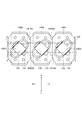
図6に示すように、多方向移動体モジュール100に用いる一対の駆動チェーン120、120の一方に設けられた回転体130の回転軸線131Aと、一対の駆動チェーン120、120の他方に設けられた回転体130の回転軸線131Aとが、相互に交差している。
具体的には、回転体130の回転軸131が、駆動チェーン120の駆動方向に対してそれぞれ所定の角度で傾いているとともに、回転体130の回転軸131の傾きが、左右の一対の駆動チェーン120で移動体モジュール本体110での前後方向の線を基準とした線対称の関係を有している。
これにより、各回転軸線131Aを無秩序に駆動チェーン120の駆動方向に斜交させる場合に比べて移動面Gから各回転体130に作用する反作用力の合力の大きさ及びその方向を設定しやすくなる。
つまり、左右方向の分力を相殺して前後方向へ多方向移動体モジュール100を移動したり、左右方向の分力を減殺または増加させてさまざまな方向へ多方向移動体モジュール100を移動したり、力の作用線上を多方向移動体モジュール100の重心Cに対してずらして回転モーメントを発生させて多方向移動体モジュール100を回転することができる。
具体的には、回転体130の回転軸131が、駆動チェーン120の駆動方向に対してそれぞれ所定の角度で傾いているとともに、回転体130の回転軸131の傾きが、左右の一対の駆動チェーン120で移動体モジュール本体110での前後方向の線を基準とした線対称の関係を有している。
これにより、各回転軸線131Aを無秩序に駆動チェーン120の駆動方向に斜交させる場合に比べて移動面Gから各回転体130に作用する反作用力の合力の大きさ及びその方向を設定しやすくなる。
つまり、左右方向の分力を相殺して前後方向へ多方向移動体モジュール100を移動したり、左右方向の分力を減殺または増加させてさまざまな方向へ多方向移動体モジュール100を移動したり、力の作用線上を多方向移動体モジュール100の重心Cに対してずらして回転モーメントを発生させて多方向移動体モジュール100を回転することができる。
図6に示すように、多方向移動体モジュール100に用いる一対の駆動チェーン120、120の一方に設けられた回転体130の回転軸線131Aが、駆動チェーン120の駆動方向に対して45°傾いている。
同様に、他方に設けられた回転体130の回転軸線131Aが、駆動チェーン120の駆動方向に対して45°傾いている。
これにより、効率よく前後方向の分力と、左右方向の分力とに分かれる。
同様に、他方に設けられた回転体130の回転軸線131Aが、駆動チェーン120の駆動方向に対して45°傾いている。
これにより、効率よく前後方向の分力と、左右方向の分力とに分かれる。
次に、図1乃至図13Bを参照しながら、前述した本実施例に係る多方向移動体モジュール100の動作を詳細に説明する。
なお、説明の便宜上、図1、図5乃至図13Bに多方向移動体モジュール100の前進方向F、後退方向B、右R及び左Lを矢印で示している。
図1、図3A、図7A乃至図13Aに示した白抜き矢印D(DR1、DR2…、DL1、DL2…)は、無端形状である無限軌道を有する駆動チェーン120のうち移動面Gの側に臨む下側部分の速度ベクトルである。
なお、説明の便宜上、図1、図5乃至図13Bに多方向移動体モジュール100の前進方向F、後退方向B、右R及び左Lを矢印で示している。
図1、図3A、図7A乃至図13Aに示した白抜き矢印D(DR1、DR2…、DL1、DL2…)は、無端形状である無限軌道を有する駆動チェーン120のうち移動面Gの側に臨む下側部分の速度ベクトルである。
なお、この速度ベクトルは、多方向移動体モジュール100を基準としたものである。
より具体的には、例えば、図1に示した駆動チェーン120のうち移動面Gの側に臨む下側部分の速度ベクトルDは、図7Aに示した駆動チェーン120の速度ベクトルDR1、DL1に一致している。
以下で示す多方向移動体モジュール100の移動方向は一例であり、多方向移動体モジュール100は、一対の駆動チェーン120、120のそれぞれの速度ベクトルの大きさ及び向きの組み合わせを変更することによって移動面G内の様々な方向に移動することができる。
より具体的には、例えば、図1に示した駆動チェーン120のうち移動面Gの側に臨む下側部分の速度ベクトルDは、図7Aに示した駆動チェーン120の速度ベクトルDR1、DL1に一致している。
以下で示す多方向移動体モジュール100の移動方向は一例であり、多方向移動体モジュール100は、一対の駆動チェーン120、120のそれぞれの速度ベクトルの大きさ及び向きの組み合わせを変更することによって移動面G内の様々な方向に移動することができる。
図7Aおよび図7Bに示すのは、右側の駆動チェーン120の速度ベクトルDR1と、左側の駆動チェーン120の速度ベクトルDL1との大きさが等しく、それらの向きが後退方向Bの場合である。
この場合、各回転体130の外周面130Sから移動面Gへ、作用力ベクトルFR1、FL1が作用する。
このうち、作用力ベクトルFR1は、右側の駆動チェーン120の回転体130の外周面130Sから移動面Gへそれぞれ作用するベクトルである。
同様に、作用力ベクトルFL1は、左側の駆動チェーン120の回転体130の外周面130Sから移動面Gへそれぞれ作用するベクトルである。
この場合、各回転体130の外周面130Sから移動面Gへ、作用力ベクトルFR1、FL1が作用する。
このうち、作用力ベクトルFR1は、右側の駆動チェーン120の回転体130の外周面130Sから移動面Gへそれぞれ作用するベクトルである。
同様に、作用力ベクトルFL1は、左側の駆動チェーン120の回転体130の外周面130Sから移動面Gへそれぞれ作用するベクトルである。
ここで、右側の駆動チェーン120の回転体130の回転軸131は、前述したように、右側が後方へ左側が前方へ傾くとともに駆動方向に対して45°傾いている。
そして、右側の駆動チェーン120の速度ベクトルDR1の向きが後退方向Bである。
したがって、作用力ベクトルFR1は、図7Aおよび図7Bに示すように、駆動方向に対して45°傾いた状態で左前から右後へ向く。
そして、右側の駆動チェーン120の速度ベクトルDR1の向きが後退方向Bである。
したがって、作用力ベクトルFR1は、図7Aおよび図7Bに示すように、駆動方向に対して45°傾いた状態で左前から右後へ向く。
同様に、左側の駆動チェーン120の回転体130の回転軸131は、前述したように、右側が前方へ左側が後方へ傾くとともに駆動方向に対して45°傾いている。
そして、左側の駆動チェーン120の速度ベクトルDL1の向きが後退方向Bである。
したがって、作用力ベクトルFL1は、図7Aおよび図7Bに示すように、駆動方向に対して45°傾いた状態で右前から左後へ向く。
そして、左側の駆動チェーン120の速度ベクトルDL1の向きが後退方向Bである。
したがって、作用力ベクトルFL1は、図7Aおよび図7Bに示すように、駆動方向に対して45°傾いた状態で右前から左後へ向く。
ここで、作用力ベクトルFR1の左右方向右向きの分力と、作用力ベクトルFL1の左右方向左向きの分力との大きさが等しく、向きが互いに逆であり、同じ線上であるため、作用力ベクトルFR1の左右方向右向きの分力と、作用力ベクトルFL1の左右方向左向きの分力とがそれぞれ相殺される。
他方、作用力ベクトルFR1の前後方向後向きの分力と、作用力ベクトルFL1の前後方向後向きの分力との大きさが等しく、向きが互いに同じであり、前後方向後向きの分力の作用線の位置が多方向移動体モジュール100の重心Cを基準に左右対称となる。
他方、作用力ベクトルFR1の前後方向後向きの分力と、作用力ベクトルFL1の前後方向後向きの分力との大きさが等しく、向きが互いに同じであり、前後方向後向きの分力の作用線の位置が多方向移動体モジュール100の重心Cを基準に左右対称となる。
そのため、作用力ベクトルFR1と作用力ベクトルFL1との和である合力ベクトルFA1の向きは、後退方向Bとなるとともに、合力ベクトルFA1の線上に多方向移動体モジュール100の重心Cが位置する。
これに応じて移動面Gから移動体モジュール100に作用する反作用力FB1の向きは前進方向Fとなるとともに、反作用力FB1の線上に多方向移動体モジュール100の重心Cが位置する。
つまり、力のモーメント(回転力)は生じない。
このため、多方向移動体モジュール100は、前進方向Fに移動する。
これに応じて移動面Gから移動体モジュール100に作用する反作用力FB1の向きは前進方向Fとなるとともに、反作用力FB1の線上に多方向移動体モジュール100の重心Cが位置する。
つまり、力のモーメント(回転力)は生じない。
このため、多方向移動体モジュール100は、前進方向Fに移動する。
図8Aおよび図8Bに示すのは、右側の駆動チェーン120の速度ベクトルDR2と、左側の駆動チェーン120の速度ベクトルDL2との大きさが等しく、それらの向きが前進方向Fの場合である。
この場合、各回転体130の外周面130Sから移動面Gへ、作用力ベクトルFR2、FL2が作用する。
このうち、作用力ベクトルFR2は、右側の駆動チェーン120の回転体130の外周面130Sから移動面Gへそれぞれ作用するベクトルである。
同様に、作用力ベクトルFL2は、左側の駆動チェーン120の回転体130の外周面130Sから移動面Gへそれぞれ作用するベクトルである。
この場合、各回転体130の外周面130Sから移動面Gへ、作用力ベクトルFR2、FL2が作用する。
このうち、作用力ベクトルFR2は、右側の駆動チェーン120の回転体130の外周面130Sから移動面Gへそれぞれ作用するベクトルである。
同様に、作用力ベクトルFL2は、左側の駆動チェーン120の回転体130の外周面130Sから移動面Gへそれぞれ作用するベクトルである。
ここで、右側の駆動チェーン120の回転体130の回転軸131は、前述したように、右側が後方へ左側が前方へ傾くとともに駆動方向に対して45°傾いている。
そして、右側の駆動チェーン120の速度ベクトルDR2の向きが前進方向Fである。
したがって、作用力ベクトルFR2は、図8Aおよび図8Bに示すように、駆動方向に対して45°傾いた状態で右後から左前へ向く。
そして、右側の駆動チェーン120の速度ベクトルDR2の向きが前進方向Fである。
したがって、作用力ベクトルFR2は、図8Aおよび図8Bに示すように、駆動方向に対して45°傾いた状態で右後から左前へ向く。
同様に、左側の駆動チェーン120の回転体130の回転軸131は、前述したように、右側が前方へ左側が後方へ傾くとともに駆動方向に対して45°傾いている。
そして、左側の駆動チェーン120の速度ベクトルDL2の向きが前進方向Fである。
したがって、作用力ベクトルFL2は、図8Aおよび図8Bに示すように、駆動方向に対して45°傾いた状態で左後から右前へ向く。
そして、左側の駆動チェーン120の速度ベクトルDL2の向きが前進方向Fである。
したがって、作用力ベクトルFL2は、図8Aおよび図8Bに示すように、駆動方向に対して45°傾いた状態で左後から右前へ向く。
ここで、作用力ベクトルFR2の左右方向左向きの分力と、作用力ベクトルFL2の左右方向右向きの分力との大きさが等しく、向きが互いに逆であり、同じ線上であるため、作用力ベクトルFR2の左右方向左向きの分力と、作用力ベクトルFL2の左右方向右向きの分力とがそれぞれ相殺される。
他方、作用力ベクトルFR2の前後方向前向きの分力と、作用力ベクトルFL2の前後方向前向きの分力との大きさが等しく、向きが互いに同じであり、前後方向前向きの分力の作用線の位置が多方向移動体モジュール100の重心Cを基準に左右対称となる。
他方、作用力ベクトルFR2の前後方向前向きの分力と、作用力ベクトルFL2の前後方向前向きの分力との大きさが等しく、向きが互いに同じであり、前後方向前向きの分力の作用線の位置が多方向移動体モジュール100の重心Cを基準に左右対称となる。
そのため、作用力ベクトルFR2と作用力ベクトルFL2との和である合力ベクトルFA2の向きは、前進方向Fとなるとともに、合力ベクトルFA2の線上に多方向移動体モジュール100の重心Cが位置する。
これに応じて移動面Gから移動体モジュール100に作用する反作用力FB2の向きは後退方向Bとなるとともに、反作用力FB2の線上に多方向移動体モジュール100の重心Cが位置する。
つまり、力のモーメント(回転力)は生じない。
このため、多方向移動体モジュール100は、後退方向Bに移動する。
これに応じて移動面Gから移動体モジュール100に作用する反作用力FB2の向きは後退方向Bとなるとともに、反作用力FB2の線上に多方向移動体モジュール100の重心Cが位置する。
つまり、力のモーメント(回転力)は生じない。
このため、多方向移動体モジュール100は、後退方向Bに移動する。
図9Aおよび図9Bに示すのは、右側の駆動チェーン120の速度ベクトルDR3と、左側の駆動チェーン120の速度ベクトルDL3との大きさが等しく、速度ベクトルDR3の向きが後退方向Bであり、速度ベクトルDL3の向きが前進方向Fの場合である。
この場合、各回転体130の外周面130Sから移動面Gへ、作用力ベクトルFR3、FL3が作用する。
このうち、作用力ベクトルFR3は、右側の駆動チェーン120の回転体130の外周面130Sから移動面Gへそれぞれ作用するベクトルである。
同様に、作用力ベクトルFL3は、左側の駆動チェーン120の回転体130の外周面130Sから移動面Gへそれぞれ作用するベクトルである。
この場合、各回転体130の外周面130Sから移動面Gへ、作用力ベクトルFR3、FL3が作用する。
このうち、作用力ベクトルFR3は、右側の駆動チェーン120の回転体130の外周面130Sから移動面Gへそれぞれ作用するベクトルである。
同様に、作用力ベクトルFL3は、左側の駆動チェーン120の回転体130の外周面130Sから移動面Gへそれぞれ作用するベクトルである。
ここで、右側の駆動チェーン120の回転体130の回転軸131は、前述したように、右側が後方へ左側が前方へ傾くとともに駆動方向に対して45°傾いている。
そして、右側の駆動チェーン120の速度ベクトルDR3の向きが後退方向Bである。
したがって、作用力ベクトルFR3は、図9Aおよび図9Bに示すように、駆動方向に対して45°傾いた状態で左前から右後へ向く。
そして、右側の駆動チェーン120の速度ベクトルDR3の向きが後退方向Bである。
したがって、作用力ベクトルFR3は、図9Aおよび図9Bに示すように、駆動方向に対して45°傾いた状態で左前から右後へ向く。
同様に、左側の駆動チェーン120の回転体130の回転軸131は、前述したように、右側が前方へ左側が後方へ傾くとともに駆動方向に対して45°傾いている。
そして、左側の駆動チェーン120の速度ベクトルDL3の向きが前進方向Fである。
したがって、作用力ベクトルFL3は、図9Aおよび図9Bに示すように、駆動方向に対して45°傾いた状態で左後から右前へ向く。
そして、左側の駆動チェーン120の速度ベクトルDL3の向きが前進方向Fである。
したがって、作用力ベクトルFL3は、図9Aおよび図9Bに示すように、駆動方向に対して45°傾いた状態で左後から右前へ向く。
ここで、作用力ベクトルFR3の左右方向右向きの分力と、作用力ベクトルFL3の左右方向右向きの分力との向きが互いに同じであるため、これらは相殺されない。
そして、作用力ベクトルFR3の左右方向右向きの分力と作用力ベクトルFL3の左右方向右向きの分力との和である並進合力ベクトルFA3Sの作用線の位置が、多方向移動体モジュール100の重心Cを通る位置になるとともに、並進合力ベクトルFA3Sの向きが、多方向移動体モジュール100を基準とした右向きとなる。
これに応じて移動面Gから移動体モジュール100に作用する並進反作用力FB3Sの作用線の位置が、多方向移動体モジュール100の重心Cを通る位置になるとともに、並進反作用力FB3Sの向きが、多方向移動体モジュール100を基準とした左向きとなる。
そして、作用力ベクトルFR3の左右方向右向きの分力と作用力ベクトルFL3の左右方向右向きの分力との和である並進合力ベクトルFA3Sの作用線の位置が、多方向移動体モジュール100の重心Cを通る位置になるとともに、並進合力ベクトルFA3Sの向きが、多方向移動体モジュール100を基準とした右向きとなる。
これに応じて移動面Gから移動体モジュール100に作用する並進反作用力FB3Sの作用線の位置が、多方向移動体モジュール100の重心Cを通る位置になるとともに、並進反作用力FB3Sの向きが、多方向移動体モジュール100を基準とした左向きとなる。
また、作用力ベクトルFR3の前後方向後向きの分力と、作用力ベクトルFL3の前後方向前向きの分力との大きさが等しく、向きが互いに逆ではあるが、前後方向の分力の作用線の位置が多方向移動体モジュール100の重心Cから離れているため、前後方向の分力は相殺させず、図9Aおよび図9B中の時計回り方向の力のモーメント(回転力)が生じる。
具体的には、作用力ベクトルFR3の前後方向後向きの分力と作用力ベクトルFL3の前後方向前向きの分力との和である回転合力ベクトルFA3Rの作用線の位置が、多方向移動体モジュール100の重心Cから離れているとともに、回転合力ベクトルFA3Rの向きが、多方向移動体モジュール100の重心Cを基準に時計回り方向となる。
これに応じて移動面Gから移動体モジュール100に作用する回転反作用力FB3Rの作用線の位置が、多方向移動体モジュール100の重心Cから離れているとともに、回転反作用力FB3Rの向きが、多方向移動体モジュール100の重心Cを基準に反時計回り方向となる。
具体的には、作用力ベクトルFR3の前後方向後向きの分力と作用力ベクトルFL3の前後方向前向きの分力との和である回転合力ベクトルFA3Rの作用線の位置が、多方向移動体モジュール100の重心Cから離れているとともに、回転合力ベクトルFA3Rの向きが、多方向移動体モジュール100の重心Cを基準に時計回り方向となる。
これに応じて移動面Gから移動体モジュール100に作用する回転反作用力FB3Rの作用線の位置が、多方向移動体モジュール100の重心Cから離れているとともに、回転反作用力FB3Rの向きが、多方向移動体モジュール100の重心Cを基準に反時計回り方向となる。
そして、並進反作用力FB3Sおよび回転反作用力FB3Rにより、多方向移動体モジュール100は、反時計回り方向に回転しながら移動面Gに対して多方向移動体モジュール100を基準とした左側へ移動する。
つまり、並進運動と回転運動とを組み合わせた移動をする。
つまり、並進運動と回転運動とを組み合わせた移動をする。
図10Aおよび図10Bに示すのは、右側の駆動チェーン120の速度ベクトルDR4と、左側の駆動チェーン120の速度ベクトルDL4との大きさが等しく、速度ベクトルDR4の向きが前進方向Fであり、速度ベクトルDL4の向きが後退方向Bの場合である。
この場合、各回転体130の外周面130Sから移動面Gへ、作用力ベクトルFR4、FL4が作用する。
このうち、作用力ベクトルFR4は、右側の駆動チェーン120の回転体130の外周面130Sから移動面Gへそれぞれ作用するベクトルである。
同様に、作用力ベクトルFL4は、左側の駆動チェーン120の回転体130の外周面130Sから移動面Gへそれぞれ作用するベクトルである。
この場合、各回転体130の外周面130Sから移動面Gへ、作用力ベクトルFR4、FL4が作用する。
このうち、作用力ベクトルFR4は、右側の駆動チェーン120の回転体130の外周面130Sから移動面Gへそれぞれ作用するベクトルである。
同様に、作用力ベクトルFL4は、左側の駆動チェーン120の回転体130の外周面130Sから移動面Gへそれぞれ作用するベクトルである。
ここで、右側の駆動チェーン120の回転体130の回転軸131は、前述したように、右側が後方へ左側が前方へ傾くとともに駆動方向に対して45°傾いている。
そして、右側の駆動チェーン120の速度ベクトルDR4の向きが前進方向Fである。
したがって、作用力ベクトルFR4は、図10Aおよび図10Bに示すように、駆動方向に対して45°傾いた状態で右後から左前へ向く。
そして、右側の駆動チェーン120の速度ベクトルDR4の向きが前進方向Fである。
したがって、作用力ベクトルFR4は、図10Aおよび図10Bに示すように、駆動方向に対して45°傾いた状態で右後から左前へ向く。
同様に、左側の駆動チェーン120の回転体130の回転軸131は、前述したように、右側が前方へ左側が後方へ傾くとともに駆動方向に対して45°傾いている。
そして、左側の駆動チェーン120の速度ベクトルDL4の向きが後退方向Bである。
したがって、作用力ベクトルFL4は、図10Aおよび図10Bに示すように、駆動方向に対して45°傾いた状態で右前から左後へ向く。
そして、左側の駆動チェーン120の速度ベクトルDL4の向きが後退方向Bである。
したがって、作用力ベクトルFL4は、図10Aおよび図10Bに示すように、駆動方向に対して45°傾いた状態で右前から左後へ向く。
ここで、作用力ベクトルFR4の左右方向左向きの分力と、作用力ベクトルFL4の左右方向左向きの分力との向きが互いに同じであるため、これらは相殺されない。
そして、作用力ベクトルFR4の左右方向左向きの分力と作用力ベクトルFL4の左右方向右向きの分力との和である並進合力ベクトルFA4Sの作用線の位置が、多方向移動体モジュール100の重心Cを通る位置になるとともに、並進合力ベクトルFA4Sの向きが、多方向移動体モジュール100を基準とした左向きとなる。
これに応じて移動面Gから移動体モジュール100に作用する並進反作用力FB4Sの作用線の位置が、多方向移動体モジュール100の重心Cを通る位置になるとともに、並進反作用力FB4Sの向きが、多方向移動体モジュール100を基準とした右向きとなる。
そして、作用力ベクトルFR4の左右方向左向きの分力と作用力ベクトルFL4の左右方向右向きの分力との和である並進合力ベクトルFA4Sの作用線の位置が、多方向移動体モジュール100の重心Cを通る位置になるとともに、並進合力ベクトルFA4Sの向きが、多方向移動体モジュール100を基準とした左向きとなる。
これに応じて移動面Gから移動体モジュール100に作用する並進反作用力FB4Sの作用線の位置が、多方向移動体モジュール100の重心Cを通る位置になるとともに、並進反作用力FB4Sの向きが、多方向移動体モジュール100を基準とした右向きとなる。
また、作用力ベクトルFR4の前後方向前向きの分力と、作用力ベクトルFL4の前後方向後向きの分力との大きさが等しく、向きが互いに逆ではあるが、前後方向の分力の作用線の位置が多方向移動体モジュール100の重心Cから離れているため、前後方向の分力は相殺させず、図10Aおよび図10B中の反時計回り方向の力のモーメント(回転力)が生じる。
具体的には、作用力ベクトルFR4の前後方向前向きの分力と作用力ベクトルFL4の前後方向後向きの分力との和である回転合力ベクトルFA4Rの作用線の位置が、多方向移動体モジュール100の重心Cから離れているとともに、回転合力ベクトルFA4Rの向きが、多方向移動体モジュール100の重心Cを基準に反時計回り方向となる。
これに応じて移動面Gから移動体モジュール100に作用する回転反作用力FB4Rの作用線の位置が、多方向移動体モジュール100の重心Cから離れているとともに、回転反作用力FB4Rの向きが、多方向移動体モジュール100の重心Cを基準に時計回り方向となる。
これに応じて移動面Gから移動体モジュール100に作用する回転反作用力FB4Rの作用線の位置が、多方向移動体モジュール100の重心Cから離れているとともに、回転反作用力FB4Rの向きが、多方向移動体モジュール100の重心Cを基準に時計回り方向となる。
そして、並進反作用力FB4Sおよび回転反作用力FB4Rにより、多方向移動体モジュール100は、時計回り方向に回転しながら移動面Gに対して多方向移動体モジュール100を基準とした右側へ移動する。
つまり、並進運動と回転運動とを組み合わせた移動をする。
つまり、並進運動と回転運動とを組み合わせた移動をする。
図11Aおよび図11Bに示すのは、一対のうちの一方である右側の駆動チェーン120の速度ベクトルの大きさがゼロであり、他方である左側の駆動チェーン120の速度ベクトルDL5の大きさがゼロより大きくてその向きが後退方向Bの場合である。
この場合、作用力ベクトルFL5が、左側の駆動チェーン120の回転体130の外周面130Sから移動面Gへそれぞれ作用する。
この場合、作用力ベクトルFL5が、左側の駆動チェーン120の回転体130の外周面130Sから移動面Gへそれぞれ作用する。
ここで、左側の駆動チェーン120の回転体130の回転軸131は、前述したように、右側が前方へ左側が後方へ傾くとともに駆動方向に対して45°傾いている。
そして、左側の駆動チェーン120の速度ベクトルDL5の向きが後退方向Bである。
したがって、作用力ベクトルFL5は、図11Aおよび図11Bに示すように、駆動方向に対して45°傾いた状態で右前から左後へ向く。
そして、左側の駆動チェーン120の速度ベクトルDL5の向きが後退方向Bである。
したがって、作用力ベクトルFL5は、図11Aおよび図11Bに示すように、駆動方向に対して45°傾いた状態で右前から左後へ向く。
同様に、右側の駆動チェーン120の回転体130の回転軸131は、前述したように、右側が後方へ左側が前方へ傾くとともに駆動方向に対して45°傾いている。
そして、右側の駆動チェーン120に設けられた回転体130が、作用力ベクトルFL5を逃がすように作用する。
そして、右側の駆動チェーン120に設けられた回転体130が、作用力ベクトルFL5を逃がすように作用する。
そのため、それぞれの作用力ベクトルFL5の和である合力ベクトルFA5の向きは、作用力ベクトルFL5と同じ向きとなる。
言い換えると、駆動方向に対して45°傾いた状態で右前から左後への向きとなる。
言い換えると、駆動方向に対して45°傾いた状態で右前から左後への向きとなる。
合力ベクトルFA5の作用線上に多方向移動体モジュール100の重心Cが位置する場合、移動面Gから移動体モジュール100に作用する反作用力FB5の向きは、駆動方向に対して45°傾いた状態で左後から右前への向きとなる。
さらに、反作用力FB5の作用線上にも多方向移動体モジュール100の重心Cが位置することとなる。
つまり、力のモーメント(回転力)は生じない。
このため、多方向移動体モジュール100は、右斜め前45°の方向へ移動(並進運動)する。
さらに、反作用力FB5の作用線上にも多方向移動体モジュール100の重心Cが位置することとなる。
つまり、力のモーメント(回転力)は生じない。
このため、多方向移動体モジュール100は、右斜め前45°の方向へ移動(並進運動)する。
なお、合力ベクトルFA5の作用線の位置が、多方向移動体モジュール100の重心Cから離れている場合、反作用力FB5の向きは、駆動方向に対して45°傾いた状態で左後から右前への向きとなるが、反作用力FB5の作用線の位置も、多方向移動体モジュール100の重心Cから離れる。
つまり、力のモーメント(回転力)が生じる。
回転運動と並進運動とが組み合わさるため、多方向移動体モジュール100は、所定の方向へ曲がりながら移動する。
例えば、反作用力FB5の作用線の位置が、多方向移動体モジュール100の重心Cより前側である場合、多方向移動体モジュール100は、右斜め前に進みながら、時計回り方向へ曲がる。
他方、反作用力FB5の作用線の位置が、多方向移動体モジュール100の重心Cより後側である場合、多方向移動体モジュール100は、右斜め前に進みながら、反時計回り方向へ曲がる。
つまり、力のモーメント(回転力)が生じる。
回転運動と並進運動とが組み合わさるため、多方向移動体モジュール100は、所定の方向へ曲がりながら移動する。
例えば、反作用力FB5の作用線の位置が、多方向移動体モジュール100の重心Cより前側である場合、多方向移動体モジュール100は、右斜め前に進みながら、時計回り方向へ曲がる。
他方、反作用力FB5の作用線の位置が、多方向移動体モジュール100の重心Cより後側である場合、多方向移動体モジュール100は、右斜め前に進みながら、反時計回り方向へ曲がる。
図12Aおよび図12Bに示すのは、一対のうちの一方である右側の駆動チェーン120の速度ベクトルDR6の大きさがゼロより大きく、他方である左側の駆動チェーン120の速度ベクトルDL6の大きさより小さく、速度ベクトルDR6の向きが前進方向Fであり、速度ベクトルDL6の向きが後退方向Bの場合である。
この場合、各回転体130の外周面130Sから移動面Gへ、作用力ベクトルFR6、FL6が作用する。
この場合、各回転体130の外周面130Sから移動面Gへ、作用力ベクトルFR6、FL6が作用する。
このうち、作用力ベクトルFR6は、右側の駆動チェーン120の回転体130の外周面130Sから移動面Gへそれぞれ作用するベクトルである。
同様に、作用力ベクトルFL6は、左側の駆動チェーン120の回転体130の外周面130Sから移動面Gへそれぞれ作用するベクトルである。
同様に、作用力ベクトルFL6は、左側の駆動チェーン120の回転体130の外周面130Sから移動面Gへそれぞれ作用するベクトルである。
ここで、右側の駆動チェーン120の回転体130の回転軸131は、前述したように、右側が後方へ左側が前方へ傾くとともに駆動方向に対して45°傾いている。
そして、右側の駆動チェーン120の速度ベクトルDR6の向きが前進方向Fである。
したがって、作用力ベクトルFR6は、図12Aおよび図12Bに示すように、駆動方向に対して45°傾いた状態で右後から左前へ向く。
そして、右側の駆動チェーン120の速度ベクトルDR6の向きが前進方向Fである。
したがって、作用力ベクトルFR6は、図12Aおよび図12Bに示すように、駆動方向に対して45°傾いた状態で右後から左前へ向く。
同様に、左側の駆動チェーン120の回転体130の回転軸131は、前述したように、右側が前方へ左側が後方へ傾くとともに駆動方向に対して45°傾いている。
そして、左側の駆動チェーン120の速度ベクトルDL6の向きが後退方向Bである。
したがって、作用力ベクトルFL6は、図12Aおよび図12Bに示すように、駆動方向に対して45°傾いた状態で右前から左後へ向く。
そして、左側の駆動チェーン120の速度ベクトルDL6の向きが後退方向Bである。
したがって、作用力ベクトルFL6は、図12Aおよび図12Bに示すように、駆動方向に対して45°傾いた状態で右前から左後へ向く。
ここで、作用力ベクトルFR6の左右方向左向きの分力と、作用力ベクトルFL6の左右方向左向きの分力との向きが互いに同じであるため、これらは相殺されない。
そして、作用力ベクトルFR6の左右方向左向きの分力と作用力ベクトルFL6の左右方向右向きの分力との和である並進合力ベクトルFA6Sの作用線の位置が、多方向移動体モジュール100の重心Cを通る位置になるとともに、並進合力ベクトルFA6Sの向きが、多方向移動体モジュール100を基準とした左向きとなる。
これに応じて移動面Gから移動体モジュール100に作用する並進反作用力FB6Sの作用線の位置が、多方向移動体モジュール100の重心Cを通る位置になるとともに、並進反作用力FB6Sの向きが、多方向移動体モジュール100を基準とした右向きとなる。
そして、作用力ベクトルFR6の左右方向左向きの分力と作用力ベクトルFL6の左右方向右向きの分力との和である並進合力ベクトルFA6Sの作用線の位置が、多方向移動体モジュール100の重心Cを通る位置になるとともに、並進合力ベクトルFA6Sの向きが、多方向移動体モジュール100を基準とした左向きとなる。
これに応じて移動面Gから移動体モジュール100に作用する並進反作用力FB6Sの作用線の位置が、多方向移動体モジュール100の重心Cを通る位置になるとともに、並進反作用力FB6Sの向きが、多方向移動体モジュール100を基準とした右向きとなる。
また、作用力ベクトルFR6の前後方向前向きの分力と、作用力ベクトルFL6の前後方向後向きの分力との向きが互いに逆ではあるが、前後方向の分力の作用線の位置が多方向移動体モジュール100の重心Cから離れているため、前後方向の分力は相殺させず、図12Aおよび図12B中の反時計回り方向の力のモーメント(回転力)が生じる。
具体的には、作用力ベクトルFR6の前後方向前向きの分力と作用力ベクトルFL6の前後方向後向きの分力との和である回転合力ベクトルFA6Rの作用線の位置が、多方向移動体モジュール100の重心Cから離れているとともに、回転合力ベクトルFA6Rの向きが、多方向移動体モジュール100の重心Cを基準に反時計回り方向となる。
これに応じて移動面Gから移動体モジュール100に作用する回転反作用力FB6Rの作用線の位置が、多方向移動体モジュール100の重心Cから離れているとともに、回転反作用力FB6Rの向きが、多方向移動体モジュール100の重心Cを基準に時計回り方向となる。
これに応じて移動面Gから移動体モジュール100に作用する回転反作用力FB6Rの作用線の位置が、多方向移動体モジュール100の重心Cから離れているとともに、回転反作用力FB6Rの向きが、多方向移動体モジュール100の重心Cを基準に時計回り方向となる。
そして、並進反作用力FB6Sおよび回転反作用力FB6Rにより、多方向移動体モジュール100は、時計回り方向に回転しながら移動面Gに対して多方向移動体モジュール100を基準とした右側へ移動する。
なお、仮に、作用力ベクトルFL6の前後方向後向きの分力の大きさを、図10Aおよび図10Bに示す場合の作用力ベクトルFL4の前後方向後向きの分力の大きさと同じとすると、作用力ベクトルFR6の前後方向前向きの分力の大きさが、図10Aおよび図10Bに示す場合の作用力ベクトルFR4の前後方向前向きの分力の大きさより小さい関係となる。
そして、図12Aおよび図12Bで示す場合の回転反作用力FB6Rの大きさは、図10Aおよび図10Bに示す場合の回転反作用力FB4Rの大きさと比べて小さくなる。
さらに、作用力ベクトルFL6の前後方向後向きの分力の大きさが、作用力ベクトルFR6の前後方向前向きの分力の大きさより大きいため、多方向移動体モジュール100の左側が右側を支点にして後退する右側の移動距離よりも大きく前進しようとする。
つまり、多方向移動体モジュール100は、右斜め前に進みながら、時計回り方向へ曲がる。
そして、図12Aおよび図12Bで示す場合の回転反作用力FB6Rの大きさは、図10Aおよび図10Bに示す場合の回転反作用力FB4Rの大きさと比べて小さくなる。
さらに、作用力ベクトルFL6の前後方向後向きの分力の大きさが、作用力ベクトルFR6の前後方向前向きの分力の大きさより大きいため、多方向移動体モジュール100の左側が右側を支点にして後退する右側の移動距離よりも大きく前進しようとする。
つまり、多方向移動体モジュール100は、右斜め前に進みながら、時計回り方向へ曲がる。
図13Aおよび図13Bに示すのは、一対のうちの一方である右側の駆動チェーン120の速度ベクトルDR7の大きさがゼロより大きく、他方である左側の速度ベクトルDL7の大きさより小さく、速度ベクトルDR7の向きが後退方向Bであり、速度ベクトルDL7の向きが後退方向Bの場合である。
この場合、各回転体130の外周面130Sから移動面Gへ、作用力ベクトルFR7、FL7が作用する。
この場合、各回転体130の外周面130Sから移動面Gへ、作用力ベクトルFR7、FL7が作用する。
このうち、作用力ベクトルFR7は、右側の駆動チェーン120の回転体130の外周面130Sから移動面Gへそれぞれ作用するベクトルである。
同様に、作用力ベクトルFL7は、左側の駆動チェーン120の回転体130の外周面130Sから移動面Gへそれぞれ作用するベクトルである。
同様に、作用力ベクトルFL7は、左側の駆動チェーン120の回転体130の外周面130Sから移動面Gへそれぞれ作用するベクトルである。
ここで、右側の駆動チェーン120の回転体130の回転軸131は、前述したように、右側が後方へ左側が前方へ傾くとともに駆動方向に対して45°傾いている。
そして、右側の駆動チェーン120の速度ベクトルDR7の向きが後退方向Bである。
したがって、作用力ベクトルFR7は、図13Aおよび図13Bに示すように、駆動方向に対して45°傾いた状態で左前から右後へ向く。
そして、右側の駆動チェーン120の速度ベクトルDR7の向きが後退方向Bである。
したがって、作用力ベクトルFR7は、図13Aおよび図13Bに示すように、駆動方向に対して45°傾いた状態で左前から右後へ向く。
同様に、左側の駆動チェーン120の回転体130の回転軸131は、前述したように、右側が前方へ左側が後方へ傾くとともに駆動方向に対して45°傾いている。
そして、左側の駆動チェーン120の速度ベクトルDL7の向きが後退方向Bである。
したがって、作用力ベクトルFL7は、図13Aおよび図13Bに示すように、駆動方向に対して45°傾いた状態で右前から左後へ向く。
そして、左側の駆動チェーン120の速度ベクトルDL7の向きが後退方向Bである。
したがって、作用力ベクトルFL7は、図13Aおよび図13Bに示すように、駆動方向に対して45°傾いた状態で右前から左後へ向く。
ここで、作用力ベクトルFR7の左右方向右向きの分力と、作用力ベクトルFL7の左右方向左向きの分力との大きさは等しくないが、向きが互いに逆であり、同じ線上であるため、作用力ベクトルFL7の左右方向左向きの分力が、作用力ベクトルFR7の左右方向右向きの分力によって減殺される。
そして、作用力ベクトルFR7の左右方向左向きの分力と作用力ベクトルFL7の左右方向右向きの分力との和である左右方向並進合力ベクトルの作用線の位置が、多方向移動体モジュール100の重心Cを通る位置になるとともに、左右方向並進合力ベクトルの向きが、多方向移動体モジュール100を基準とした左向きとなる。
そして、作用力ベクトルFR7の左右方向左向きの分力と作用力ベクトルFL7の左右方向右向きの分力との和である左右方向並進合力ベクトルの作用線の位置が、多方向移動体モジュール100の重心Cを通る位置になるとともに、左右方向並進合力ベクトルの向きが、多方向移動体モジュール100を基準とした左向きとなる。
また、作用力ベクトルFR7の前後方向後向きの分力と、作用力ベクトルFL7の前後方向後向きの分力との向きが互いに同じではあるが、大きさが互いに等しくなく、前後方向の分力の作用線の位置が多方向移動体モジュール100の重心Cから離れているが左右対称の位置関係となるため、前後方向後向きに並進する前後方向並進合力ベクトルと、図13Aおよび図13B中の反時計回り方向の力のモーメント(回転力)とが生じる。
具体的に、前後方向並進合力ベクトルは、作用力ベクトルFR7の前後方向後向きの分力と、作用力ベクトルFL7の前後方向後向きの分力のうちの作用力ベクトルFR7の前後方向後向きの分力と同じ大きさの分との和である。
具体的に、前後方向並進合力ベクトルは、作用力ベクトルFR7の前後方向後向きの分力と、作用力ベクトルFL7の前後方向後向きの分力のうちの作用力ベクトルFR7の前後方向後向きの分力と同じ大きさの分との和である。
他方、力のモーメント(回転力)である回転合力ベクトルFA7Rの大きさは、作用力ベクトルFL7の前後方向後向きの分力の大きさと作用力ベクトルFR7の前後方向後向きの分力の大きさとの差である。
また、回転合力ベクトルFA7Rの作用線の位置が、多方向移動体モジュール100の重心Cから離れているとともに、回転合力ベクトルFA7Rの向きが、多方向移動体モジュール100の重心Cを基準に反時計回り方向となる。
これに応じて移動面Gから移動体モジュール100に作用する回転反作用力FB7Rの作用線の位置が、多方向移動体モジュール100の重心Cから離れているとともに、回転反作用力FB7Rの向きが、多方向移動体モジュール100の重心Cを基準に時計回り方向となる。
また、回転合力ベクトルFA7Rの作用線の位置が、多方向移動体モジュール100の重心Cから離れているとともに、回転合力ベクトルFA7Rの向きが、多方向移動体モジュール100の重心Cを基準に反時計回り方向となる。
これに応じて移動面Gから移動体モジュール100に作用する回転反作用力FB7Rの作用線の位置が、多方向移動体モジュール100の重心Cから離れているとともに、回転反作用力FB7Rの向きが、多方向移動体モジュール100の重心Cを基準に時計回り方向となる。
また、左右方向並進合力ベクトルと前後方向並進合力ベクトルとの和である並進合力ベクトルFA7Sの作用線の位置が、多方向移動体モジュール100の重心Cを通る位置になるとともに、並進合力ベクトルFA7Sの向きが、多方向移動体モジュール100を基準とした左斜め後向きとなる。
これに応じて移動面Gから移動体モジュール100に作用する並進反作用力FB7Sの作用線の位置が、多方向移動体モジュール100の重心Cを通る位置になるとともに、並進反作用力FB7Sの向きが、多方向移動体モジュール100を基準とした右斜め前向きとなる。
これに応じて移動面Gから移動体モジュール100に作用する並進反作用力FB7Sの作用線の位置が、多方向移動体モジュール100の重心Cを通る位置になるとともに、並進反作用力FB7Sの向きが、多方向移動体モジュール100を基準とした右斜め前向きとなる。
そして、並進反作用力FB7Sおよび回転反作用力FB7Rにより、多方向移動体モジュール100は、時計回り方向に回転しながら移動面Gに対して多方向移動体モジュール100を基準とした右斜め前側へ移動する。
つまり、多方向移動体モジュール100は、図12Aに示す場合と比べて大きく前寄りの右斜め前に進みながら、時計回り方向へ曲がる。
つまり、多方向移動体モジュール100は、図12Aに示す場合と比べて大きく前寄りの右斜め前に進みながら、時計回り方向へ曲がる。
このようにして得られた本実施例の多方向移動体モジュール100は、移動面G上を移動する移動体モジュール本体110と、この移動体モジュール本体110の左右それぞれで前後に設けられた駆動用スプロケット111RF、111LBおよび従動部材112RB、112LFと、左右のそれぞれの駆動用スプロケット111RF、111LBおよび従動部材112RB、112LFに巻き掛けられた状態で左右独立して進退自在に駆動される一対の駆動チェーン120、120と、駆動チェーン120の外周側で駆動チェーン120の駆動方向に沿って回転自在に配設され、回転軸131を有して移動面Gに外周面130Sをそれぞれ接触させる複数の回転体130と、駆動チェーン120の外周側に配列された状態でそれぞれ固定されて駆動チェーン120の姿勢の変化に応じて対向端面141AS、141AS同士を当接自在な複数のチェーン屈曲規制用ブロック体である固定用台座部140Aとを備え、回転体130の回転軸131が、駆動チェーン120の駆動方向に対してそれぞれ所定の角度で傾いているとともに、回転体130の回転軸131の傾きが、左右の一対の駆動チェーン120、120で移動体モジュール本体110での前後方向の線を基準とした線対称の関係を有し、駆動チェーン120の姿勢が駆動用スプロケット111および従動部材112の外周に沿って曲がったとき、固定用台座部140Aのチェーン長手方向で隣り合う対向端面141AS、141AS同士が、チェーン長手方向で互いに離間し、駆動チェーン120の姿勢がチェーン長手方向に直線状になったとき、固定用台座部140Aのチェーン長手方向で隣り合う対向端面141AS、141AS同士が、チェーン長手方向で互いに当接する構成であることにより、操舵機構の複雑化と移動機構の高くなりがちな重心Cと移動面G側に繰り出されたチェーン部分の撓みとチェーン寿命の低下とを同時に防ぐとともに回転体130の荷重負担の軽減と部品点数の削減と省スペース化とを実現し、十分な駆動力を得て円滑に移動及び転回することができるなど、その効果は甚大である。
次に、図14乃至図16に基づいて、上述した多方向移動体モジュール100の変形例を説明する。
なお、本変形例の多方向移動体モジュールでは、上述のチェーン屈曲規制用ブロック体として固定用台座部140Aの代わりに壁状ブロック体140Bを用いている点のみで相違するため、上述の多方向移動体モジュール100と共通する部分に共通の参照符号を付し、その詳細な説明を省略する。
なお、本変形例の多方向移動体モジュールでは、上述のチェーン屈曲規制用ブロック体として固定用台座部140Aの代わりに壁状ブロック体140Bを用いている点のみで相違するため、上述の多方向移動体モジュール100と共通する部分に共通の参照符号を付し、その詳細な説明を省略する。
図14乃至図16に示すように、本変形例の多方向移動体モジュールに用いる回転体130の側方に設置された一対の壁状ブロック体140B、140Bでのチェーン長手方向外側側面142BSは、回転体130の外周面130Sでの移動面Gに接触する接触線130Lより駆動チェーン120の内周寄りに形成されている。
これにより、駆動チェーン120の屈曲を規制する箇所が、所謂、チェーン屈曲支点から遠方でてこ比の小さくなる回転体130の側方となる。
これにより、駆動チェーン120の屈曲を規制する箇所が、所謂、チェーン屈曲支点から遠方でてこ比の小さくなる回転体130の側方となる。
このようにして得られた本変形例の多方向移動体モジュールは、チェーン屈曲規制用ブロック体が、回転体130の側方に設置された一対の壁状ブロック体140B、140Bから構成されているとともに、この壁状ブロック体140Bでのチェーン長手方向外側側面142BSが、回転体130の外周面130Sでの移動面Gに接触する接触線130Lより駆動チェーン120の内周寄りに形成されていることにより、回転体130と移動面Gとの相互接触を確実に維持できるなど、その効果は甚大である。
100 ・・・ 多方向移動体モジュール
110 ・・・ 移動体モジュール本体
111、111RF、111LB ・・・ 駆動用スプロケット
112、112RB、112LF ・・・ 従動部材
113F、113B ・・・ 駆動モータ
114RF、1414LB ・・・ 駆動軸
114RB、114LF ・・・ 従動軸
120 ・・・ 駆動チェーン
130 ・・・ 回転体
130L ・・・ 移動面に接触する接触線
130S ・・・ 回転体の外周面
131 ・・・ 回転軸
131A ・・・ 回転軸線
140A ・・・ 固定用台座部
141AS ・・・ 固定用台座の対向端面
140B ・・・ 壁状ブロック体
141BS ・・・ 壁状ブロック体の対向端面
142BS ・・・ 壁状ブロック体の外側側面
C ・・・ 多方向移動体モジュールの重心
D ・・・ 駆動チェーン部分の速度ベクトル
DR1、DR2、DR3、DR4、DR6、DR7 ・・・ 右側に設けられた駆動チェーン部分の速度ベクトル
DL1、DL2、DL3、DL4、DL5、DL6、DL7 ・・・ 左側に設けられた駆動チェーン部分の速度ベクトル
FR1、FR2、FR3、FR4、FR6、FR7 ・・・ 右側回転体の作用力
FL1、FL2、FL3、FL4、FL5、FL6、FL7 ・・・ 左側回転体の作用力
FA1、FA2、FA3、FA4、FA5、FA6、FA7 ・・・ 合力ベクトル
FB1、FB2、FB3、FB4、FB5、FB6、FB7 ・・・ 反作用力
G ・・・ 多方向移動体モジュールの移動面
F ・・・ 多方向移動体モジュールの前進方向
B ・・・ 多方向移動体モジュールの後退方向
R ・・・ 多方向移動体モジュールの右方向
L ・・・ 多方向移動体モジュールの左方向
110 ・・・ 移動体モジュール本体
111、111RF、111LB ・・・ 駆動用スプロケット
112、112RB、112LF ・・・ 従動部材
113F、113B ・・・ 駆動モータ
114RF、1414LB ・・・ 駆動軸
114RB、114LF ・・・ 従動軸
120 ・・・ 駆動チェーン
130 ・・・ 回転体
130L ・・・ 移動面に接触する接触線
130S ・・・ 回転体の外周面
131 ・・・ 回転軸
131A ・・・ 回転軸線
140A ・・・ 固定用台座部
141AS ・・・ 固定用台座の対向端面
140B ・・・ 壁状ブロック体
141BS ・・・ 壁状ブロック体の対向端面
142BS ・・・ 壁状ブロック体の外側側面
C ・・・ 多方向移動体モジュールの重心
D ・・・ 駆動チェーン部分の速度ベクトル
DR1、DR2、DR3、DR4、DR6、DR7 ・・・ 右側に設けられた駆動チェーン部分の速度ベクトル
DL1、DL2、DL3、DL4、DL5、DL6、DL7 ・・・ 左側に設けられた駆動チェーン部分の速度ベクトル
FR1、FR2、FR3、FR4、FR6、FR7 ・・・ 右側回転体の作用力
FL1、FL2、FL3、FL4、FL5、FL6、FL7 ・・・ 左側回転体の作用力
FA1、FA2、FA3、FA4、FA5、FA6、FA7 ・・・ 合力ベクトル
FB1、FB2、FB3、FB4、FB5、FB6、FB7 ・・・ 反作用力
G ・・・ 多方向移動体モジュールの移動面
F ・・・ 多方向移動体モジュールの前進方向
B ・・・ 多方向移動体モジュールの後退方向
R ・・・ 多方向移動体モジュールの右方向
L ・・・ 多方向移動体モジュールの左方向
Claims (5)
- 移動面上を移動する移動体モジュール本体と、
該移動体モジュール本体の左右それぞれで前後に設けられた駆動用スプロケットおよび従動部材と、
前記左右のそれぞれの駆動用スプロケットおよび従動部材に巻き掛けられた状態で左右独立して進退自在に駆動される一対の駆動チェーンと、
前記駆動チェーンの外周側で駆動チェーンの駆動方向に沿って回転自在に配設され、回転軸を有して移動面に外周面をそれぞれ接触させる複数の回転体と、
前記駆動チェーンの外周側に配列された状態でそれぞれ固定されて駆動チェーンの姿勢の変化に応じて対向端面同士を当接自在な複数のチェーン屈曲規制用ブロック体とを備え、
前記回転体の回転軸が、前記駆動チェーンの駆動方向に対してそれぞれ所定の角度で傾いているとともに、前記回転体の回転軸の傾きが、前記左右の一対の駆動チェーンで移動体モジュール本体での前後方向の線を基準とした線対称の関係を有し、
前記駆動チェーンの姿勢が駆動用スプロケットおよび従動部材の外周に沿って曲がったとき、前記チェーン屈曲規制用ブロック体のチェーン長手方向で隣り合う対向端面同士が、前記チェーン長手方向で互いに離間し、
前記駆動チェーンの姿勢がチェーン長手方向に直線状になったとき、前記チェーン屈曲規制用ブロック体のチェーン長手方向で隣り合う対向端面同士が、前記チェーン長手方向で互いに当接する構成であることを特徴とする多方向移動体モジュール。 - 前記チェーン屈曲規制用ブロック体が、前記回転体の側方に設置された一対の壁状ブロック体から構成されているとともに、
該壁状ブロック体でのチェーン長手方向外側側面が、前記回転体の外周面での移動面に接触する接触線より前記駆動チェーンの内周寄りに形成されていることを特徴とする請求項1に記載の多方向移動体モジュール。 - 前記チェーン屈曲規制用ブロック体が、前記回転体を駆動チェーンに固定する固定用台座部であることを特徴とする請求項1に記載の多方向移動体モジュール。
- 前記一対の駆動チェーンのそれぞれの駆動方向が、相互に平行な関係であることを特徴とする請求項1に記載の多方向移動体モジュール。
- 前記一対の駆動チェーンの一方に設けられた回転体の回転軸線と前記一対の駆動チェーンの他方に設けられた回転体の回転軸線とが、前記駆動チェーンの駆動方向に対してそれぞれ45°傾いていることを特徴とする請求項1に記載の多方向移動体モジュール。
Applications Claiming Priority (2)
| Application Number | Priority Date | Filing Date | Title |
|---|---|---|---|
| JP2012-064221 | 2012-03-21 | ||
| JP2012064221 | 2012-03-21 |
Publications (1)
| Publication Number | Publication Date |
|---|---|
| WO2013141017A1 true WO2013141017A1 (ja) | 2013-09-26 |
Family
ID=49222479
Family Applications (1)
| Application Number | Title | Priority Date | Filing Date |
|---|---|---|---|
| PCT/JP2013/055995 Ceased WO2013141017A1 (ja) | 2012-03-21 | 2013-03-05 | 多方向移動体モジュール |
Country Status (1)
| Country | Link |
|---|---|
| WO (1) | WO2013141017A1 (ja) |
Cited By (3)
| Publication number | Priority date | Publication date | Assignee | Title |
|---|---|---|---|---|
| WO2016012592A1 (en) * | 2014-07-25 | 2016-01-28 | Pasquato Gaetano | Crawler track with structurally limited flexibility for terrestrial vehicles |
| CN106627823A (zh) * | 2016-12-06 | 2017-05-10 | 哈工大机器人集团上海有限公司 | 一种全向运动的机器人传动履带 |
| KR102451381B1 (ko) * | 2021-06-29 | 2022-10-06 | 충남대학교산학협력단 | 이동로봇의 횡방향 이동 장치 |
Citations (5)
| Publication number | Priority date | Publication date | Assignee | Title |
|---|---|---|---|---|
| JPS526336U (ja) * | 1975-06-30 | 1977-01-17 | ||
| JPS60173476U (ja) * | 1984-04-25 | 1985-11-16 | 株式会社神戸製鋼所 | クロ−ラシユ− |
| JPH0664567A (ja) * | 1992-08-19 | 1994-03-08 | Kansai Electric Power Co Inc:The | 履帯式走行体および履帯式走行装置 |
| JPH1143082A (ja) * | 1997-07-30 | 1999-02-16 | Matsuda Plantec Kk | 全方向移動装置 |
| JP2004344435A (ja) * | 2003-05-22 | 2004-12-09 | Japan Science & Technology Agency | パワーアシスト型移動台車 |
-
2013
- 2013-03-05 WO PCT/JP2013/055995 patent/WO2013141017A1/ja not_active Ceased
Patent Citations (5)
| Publication number | Priority date | Publication date | Assignee | Title |
|---|---|---|---|---|
| JPS526336U (ja) * | 1975-06-30 | 1977-01-17 | ||
| JPS60173476U (ja) * | 1984-04-25 | 1985-11-16 | 株式会社神戸製鋼所 | クロ−ラシユ− |
| JPH0664567A (ja) * | 1992-08-19 | 1994-03-08 | Kansai Electric Power Co Inc:The | 履帯式走行体および履帯式走行装置 |
| JPH1143082A (ja) * | 1997-07-30 | 1999-02-16 | Matsuda Plantec Kk | 全方向移動装置 |
| JP2004344435A (ja) * | 2003-05-22 | 2004-12-09 | Japan Science & Technology Agency | パワーアシスト型移動台車 |
Cited By (3)
| Publication number | Priority date | Publication date | Assignee | Title |
|---|---|---|---|---|
| WO2016012592A1 (en) * | 2014-07-25 | 2016-01-28 | Pasquato Gaetano | Crawler track with structurally limited flexibility for terrestrial vehicles |
| CN106627823A (zh) * | 2016-12-06 | 2017-05-10 | 哈工大机器人集团上海有限公司 | 一种全向运动的机器人传动履带 |
| KR102451381B1 (ko) * | 2021-06-29 | 2022-10-06 | 충남대학교산학협력단 | 이동로봇의 횡방향 이동 장치 |
Similar Documents
| Publication | Publication Date | Title |
|---|---|---|
| US6179073B1 (en) | Hybrid track for a vehicle | |
| JP2014196004A (ja) | 多方向移動体モジュール | |
| US20070137905A1 (en) | Traveling robot | |
| JP7591459B2 (ja) | 走行車 | |
| JP4759323B2 (ja) | クローラ型走行装置 | |
| KR102332149B1 (ko) | 이동식 플랫폼 | |
| US20100270856A1 (en) | Crawler-type travel device and rotational wheel assembly | |
| CN103608238A (zh) | 无人搬运车 | |
| KR102451381B1 (ko) | 이동로봇의 횡방향 이동 장치 | |
| WO2013022017A1 (ja) | 多方向移動体モジュール | |
| US8678408B2 (en) | Travel device for transport vehicle | |
| CA3013730C (en) | Suspension, and straddle-type vehicle, snow mobile, and all-terrain vehicle with the suspension | |
| CN101327887A (zh) | 用于垂直电梯的驱动装置 | |
| KR101769111B1 (ko) | 전방향 무한궤도 벨트 장치 | |
| JP2015221610A (ja) | クローラ走行装置 | |
| KR102597420B1 (ko) | 모듈형 듀얼 스위블 휠 및 이를 포함하는 플랫폼 | |
| JP2013193614A (ja) | 多方向移動体モジュール | |
| JP2004189225A (ja) | 移動式クレーンの下部構造体 | |
| KR20190073049A (ko) | 전방향 구동 장치 및 전방향 구동 차량 | |
| US11090998B2 (en) | Vehicle including a first axle beam and a second axle beam coupled together via a link | |
| KR101680318B1 (ko) | 전방향 휠 구조체 | |
| CN213165376U (zh) | 一种轻载的轨道机器人快拆式运动装置 | |
| CN108016518A (zh) | 一种新式麦轮履带车 | |
| WO2013022013A1 (ja) | 多方向移動体モジュール | |
| KR101986448B1 (ko) | 볼타이어 구동 시스템 |
Legal Events
| Date | Code | Title | Description |
|---|---|---|---|
| 121 | Ep: the epo has been informed by wipo that ep was designated in this application |
Ref document number: 13764861 Country of ref document: EP Kind code of ref document: A1 |
|
| NENP | Non-entry into the national phase |
Ref country code: DE |
|
| 122 | Ep: pct application non-entry in european phase |
Ref document number: 13764861 Country of ref document: EP Kind code of ref document: A1 |
|
| NENP | Non-entry into the national phase |
Ref country code: JP |