WO2013137285A1 - 非水電解質二次電池 - Google Patents
非水電解質二次電池 Download PDFInfo
- Publication number
- WO2013137285A1 WO2013137285A1 PCT/JP2013/056903 JP2013056903W WO2013137285A1 WO 2013137285 A1 WO2013137285 A1 WO 2013137285A1 JP 2013056903 W JP2013056903 W JP 2013056903W WO 2013137285 A1 WO2013137285 A1 WO 2013137285A1
- Authority
- WO
- WIPO (PCT)
- Prior art keywords
- positive electrode
- negative electrode
- electrolyte secondary
- aqueous electrolyte
- secondary battery
- Prior art date
- Legal status (The legal status is an assumption and is not a legal conclusion. Google has not performed a legal analysis and makes no representation as to the accuracy of the status listed.)
- Ceased
Links
Images


Classifications
-
- H—ELECTRICITY
- H01—ELECTRIC ELEMENTS
- H01M—PROCESSES OR MEANS, e.g. BATTERIES, FOR THE DIRECT CONVERSION OF CHEMICAL ENERGY INTO ELECTRICAL ENERGY
- H01M10/00—Secondary cells; Manufacture thereof
- H01M10/04—Construction or manufacture in general
- H01M10/0413—Large-sized flat cells or batteries for motive or stationary systems with plate-like electrodes
-
- H—ELECTRICITY
- H01—ELECTRIC ELEMENTS
- H01M—PROCESSES OR MEANS, e.g. BATTERIES, FOR THE DIRECT CONVERSION OF CHEMICAL ENERGY INTO ELECTRICAL ENERGY
- H01M10/00—Secondary cells; Manufacture thereof
- H01M10/05—Accumulators with non-aqueous electrolyte
- H01M10/052—Li-accumulators
- H01M10/0525—Rocking-chair batteries, i.e. batteries with lithium insertion or intercalation in both electrodes; Lithium-ion batteries
-
- H—ELECTRICITY
- H01—ELECTRIC ELEMENTS
- H01M—PROCESSES OR MEANS, e.g. BATTERIES, FOR THE DIRECT CONVERSION OF CHEMICAL ENERGY INTO ELECTRICAL ENERGY
- H01M10/00—Secondary cells; Manufacture thereof
- H01M10/05—Accumulators with non-aqueous electrolyte
- H01M10/056—Accumulators with non-aqueous electrolyte characterised by the materials used as electrolytes, e.g. mixed inorganic/organic electrolytes
- H01M10/0564—Accumulators with non-aqueous electrolyte characterised by the materials used as electrolytes, e.g. mixed inorganic/organic electrolytes the electrolyte being constituted of organic materials only
- H01M10/0566—Liquid materials
- H01M10/0569—Liquid materials characterised by the solvents
-
- H—ELECTRICITY
- H01—ELECTRIC ELEMENTS
- H01M—PROCESSES OR MEANS, e.g. BATTERIES, FOR THE DIRECT CONVERSION OF CHEMICAL ENERGY INTO ELECTRICAL ENERGY
- H01M4/00—Electrodes
- H01M4/02—Electrodes composed of, or comprising, active material
- H01M4/36—Selection of substances as active materials, active masses, active liquids
- H01M4/48—Selection of substances as active materials, active masses, active liquids of inorganic oxides or hydroxides
- H01M4/485—Selection of substances as active materials, active masses, active liquids of inorganic oxides or hydroxides of mixed oxides or hydroxides for inserting or intercalating light metals, e.g. LiTi2O4 or LiTi2OxFy
-
- H—ELECTRICITY
- H01—ELECTRIC ELEMENTS
- H01M—PROCESSES OR MEANS, e.g. BATTERIES, FOR THE DIRECT CONVERSION OF CHEMICAL ENERGY INTO ELECTRICAL ENERGY
- H01M4/00—Electrodes
- H01M4/02—Electrodes composed of, or comprising, active material
- H01M4/36—Selection of substances as active materials, active masses, active liquids
- H01M4/48—Selection of substances as active materials, active masses, active liquids of inorganic oxides or hydroxides
- H01M4/50—Selection of substances as active materials, active masses, active liquids of inorganic oxides or hydroxides of manganese
- H01M4/502—Selection of substances as active materials, active masses, active liquids of inorganic oxides or hydroxides of manganese for non-aqueous cells
-
- H—ELECTRICITY
- H01—ELECTRIC ELEMENTS
- H01M—PROCESSES OR MEANS, e.g. BATTERIES, FOR THE DIRECT CONVERSION OF CHEMICAL ENERGY INTO ELECTRICAL ENERGY
- H01M4/00—Electrodes
- H01M4/02—Electrodes composed of, or comprising, active material
- H01M4/36—Selection of substances as active materials, active masses, active liquids
- H01M4/48—Selection of substances as active materials, active masses, active liquids of inorganic oxides or hydroxides
- H01M4/50—Selection of substances as active materials, active masses, active liquids of inorganic oxides or hydroxides of manganese
- H01M4/505—Selection of substances as active materials, active masses, active liquids of inorganic oxides or hydroxides of manganese of mixed oxides or hydroxides containing manganese for inserting or intercalating light metals, e.g. LiMn2O4 or LiMn2OxFy
-
- H—ELECTRICITY
- H01—ELECTRIC ELEMENTS
- H01M—PROCESSES OR MEANS, e.g. BATTERIES, FOR THE DIRECT CONVERSION OF CHEMICAL ENERGY INTO ELECTRICAL ENERGY
- H01M4/00—Electrodes
- H01M4/02—Electrodes composed of, or comprising, active material
- H01M4/36—Selection of substances as active materials, active masses, active liquids
- H01M4/48—Selection of substances as active materials, active masses, active liquids of inorganic oxides or hydroxides
- H01M4/52—Selection of substances as active materials, active masses, active liquids of inorganic oxides or hydroxides of nickel, cobalt or iron
- H01M4/523—Selection of substances as active materials, active masses, active liquids of inorganic oxides or hydroxides of nickel, cobalt or iron for non-aqueous cells
-
- H—ELECTRICITY
- H01—ELECTRIC ELEMENTS
- H01M—PROCESSES OR MEANS, e.g. BATTERIES, FOR THE DIRECT CONVERSION OF CHEMICAL ENERGY INTO ELECTRICAL ENERGY
- H01M4/00—Electrodes
- H01M4/02—Electrodes composed of, or comprising, active material
- H01M4/36—Selection of substances as active materials, active masses, active liquids
- H01M4/48—Selection of substances as active materials, active masses, active liquids of inorganic oxides or hydroxides
- H01M4/52—Selection of substances as active materials, active masses, active liquids of inorganic oxides or hydroxides of nickel, cobalt or iron
- H01M4/525—Selection of substances as active materials, active masses, active liquids of inorganic oxides or hydroxides of nickel, cobalt or iron of mixed oxides or hydroxides containing iron, cobalt or nickel for inserting or intercalating light metals, e.g. LiNiO2, LiCoO2 or LiCoOxFy
-
- H—ELECTRICITY
- H01—ELECTRIC ELEMENTS
- H01M—PROCESSES OR MEANS, e.g. BATTERIES, FOR THE DIRECT CONVERSION OF CHEMICAL ENERGY INTO ELECTRICAL ENERGY
- H01M50/00—Constructional details or processes of manufacture of the non-active parts of electrochemical cells other than fuel cells, e.g. hybrid cells
- H01M50/10—Primary casings; Jackets or wrappings
- H01M50/102—Primary casings; Jackets or wrappings characterised by their shape or physical structure
- H01M50/105—Pouches or flexible bags
-
- H—ELECTRICITY
- H01—ELECTRIC ELEMENTS
- H01M—PROCESSES OR MEANS, e.g. BATTERIES, FOR THE DIRECT CONVERSION OF CHEMICAL ENERGY INTO ELECTRICAL ENERGY
- H01M50/00—Constructional details or processes of manufacture of the non-active parts of electrochemical cells other than fuel cells, e.g. hybrid cells
- H01M50/10—Primary casings; Jackets or wrappings
- H01M50/102—Primary casings; Jackets or wrappings characterised by their shape or physical structure
- H01M50/107—Primary casings; Jackets or wrappings characterised by their shape or physical structure having curved cross-section, e.g. round or elliptic
-
- H—ELECTRICITY
- H01—ELECTRIC ELEMENTS
- H01M—PROCESSES OR MEANS, e.g. BATTERIES, FOR THE DIRECT CONVERSION OF CHEMICAL ENERGY INTO ELECTRICAL ENERGY
- H01M2220/00—Batteries for particular applications
- H01M2220/20—Batteries in motive systems, e.g. vehicle, ship, plane
-
- H—ELECTRICITY
- H01—ELECTRIC ELEMENTS
- H01M—PROCESSES OR MEANS, e.g. BATTERIES, FOR THE DIRECT CONVERSION OF CHEMICAL ENERGY INTO ELECTRICAL ENERGY
- H01M2300/00—Electrolytes
- H01M2300/0017—Non-aqueous electrolytes
- H01M2300/0025—Organic electrolyte
- H01M2300/0028—Organic electrolyte characterised by the solvent
- H01M2300/0037—Mixture of solvents
-
- Y—GENERAL TAGGING OF NEW TECHNOLOGICAL DEVELOPMENTS; GENERAL TAGGING OF CROSS-SECTIONAL TECHNOLOGIES SPANNING OVER SEVERAL SECTIONS OF THE IPC; TECHNICAL SUBJECTS COVERED BY FORMER USPC CROSS-REFERENCE ART COLLECTIONS [XRACs] AND DIGESTS
- Y02—TECHNOLOGIES OR APPLICATIONS FOR MITIGATION OR ADAPTATION AGAINST CLIMATE CHANGE
- Y02E—REDUCTION OF GREENHOUSE GAS [GHG] EMISSIONS, RELATED TO ENERGY GENERATION, TRANSMISSION OR DISTRIBUTION
- Y02E60/00—Enabling technologies; Technologies with a potential or indirect contribution to GHG emissions mitigation
- Y02E60/10—Energy storage using batteries
-
- Y—GENERAL TAGGING OF NEW TECHNOLOGICAL DEVELOPMENTS; GENERAL TAGGING OF CROSS-SECTIONAL TECHNOLOGIES SPANNING OVER SEVERAL SECTIONS OF THE IPC; TECHNICAL SUBJECTS COVERED BY FORMER USPC CROSS-REFERENCE ART COLLECTIONS [XRACs] AND DIGESTS
- Y02—TECHNOLOGIES OR APPLICATIONS FOR MITIGATION OR ADAPTATION AGAINST CLIMATE CHANGE
- Y02P—CLIMATE CHANGE MITIGATION TECHNOLOGIES IN THE PRODUCTION OR PROCESSING OF GOODS
- Y02P70/00—Climate change mitigation technologies in the production process for final industrial or consumer products
- Y02P70/50—Manufacturing or production processes characterised by the final manufactured product
Definitions
- the present invention relates to a nonaqueous electrolyte secondary battery provided with a laminated electrode body.
- non-aqueous electrolyte secondary batteries represented by lithium ion secondary batteries are often used as driving power sources for portable electronic devices such as mobile phones, portable personal computers, and portable music players.
- electric vehicles EV
- hybrid electric vehicles HEV
- plug-in hybrid electric vehicles PHEV
- electric motorcycles etc.
- non-aqueous electrolyte secondary batteries Electric vehicles are being actively developed.
- development of medium-sized non-aqueous electrolyte secondary batteries is being promoted as a secondary battery used in a large power storage system for the purpose of storing midnight power or photovoltaic power generation.
- Non-aqueous electrolyte secondary batteries used in such electric vehicles and large power storage systems are required to have a high capacity and a high energy density, and because of the necessity of rapid charging and high load discharge, Improvement of battery characteristics (load characteristics) when charging / discharging is strongly demanded.
- non-aqueous electrolyte secondary batteries used in electric vehicles, large power storage systems, etc. require a longer battery life than secondary batteries for small portable devices, and the battery characteristics do not deteriorate even if the charge / discharge cycle progresses. It becomes important.
- a non-aqueous electrolyte secondary battery having a high capacity and a high energy density As a non-aqueous electrolyte secondary battery having a high capacity and a high energy density, a non-aqueous electrolyte secondary battery having a laminated electrode body in which a positive electrode plate and a negative electrode plate having a large area are laminated via a separator is effective.
- a non-aqueous electrolyte secondary battery including a laminated electrode body in which a positive electrode plate and a negative electrode plate having a large area are stacked with a separator interposed therebetween gas generated by decomposition of the electrolytic solution or the like is generated from the inside of the electrode body to the outside. It becomes difficult to come off. As a result, the charge / discharge reaction becomes non-uniform, resulting in a problem that the deterioration of the battery performance accompanying the charge / discharge cycle is accelerated.
- the electrode body In the case of a wound electrode body in which a long positive electrode plate and a negative electrode plate are wound through a separator, the electrode body is likely to loosen or bend due to expansion / contraction of the electrode body accompanying charge / discharge, The gas generated inside the electrode body tends to escape to the outside of the electrode body.
- the component pressure applied to each part is substantially uniform. Therefore, even if the electrode body expands or contracts due to charging / discharging, the electrode body is unlikely to loosen or bend. Gas is difficult to escape from.
- the non-aqueous electrolyte secondary battery using a laminated electrode body composed of a large-area electrode plate is deteriorated in battery performance due to the charge / discharge cycle compared to the non-aqueous electrolyte secondary battery using a wound electrode body. Is remarkable.
- Patent Document 1 and Patent Document 2 disclose prior arts that disclose the use of a lithium transition metal composite oxide synthesized under conditions rich in lithium with respect to a transition metal as a positive electrode active material.
- the present invention solves the above-described problems, and an object thereof is to provide a non-aqueous electrolyte secondary battery excellent in high-temperature cycle characteristics.
- the non-aqueous electrolyte secondary battery of the present invention includes a square positive electrode plate having a positive electrode active material layer formed on the surface of the positive electrode core, and a square electrode having a negative electrode active material layer formed on the surface of the negative electrode core.
- the proportion of the chain carbonate contained in the non-aqueous solvent is 50% by volume or more with respect to the non-aqueous solvent, and the proportion of diethyl carbonate contained in the chain carbonate in the chain carbonate It is characterized by being 70% by volume or more.
- a high-capacity nonaqueous electrolyte secondary battery provided with a mold electrode body is obtained.
- the proportion of the chain carbonate contained in the nonaqueous solvent is 50% by volume or more with respect to the nonaqueous solvent, and the proportion of the diethyl carbonate contained in the chain carbonate is the chain carbonate.
- the length of the side where the current collecting tab is provided in each electrode plate is referred to as “width”, and the length of the side perpendicular to the side where the current collecting tab is provided is referred to as “height”.
- the “width” and “height” are the lengths of the regions where the active material layer is formed on the electrode plate.
- a non-aqueous electrolyte secondary battery having improved deformation resistance and stable against impact is obtained by using a laminated electrode body in which 10 or more positive electrode plates and 10 negative electrode plates are stacked. It is done.
- the negative electrode active material layer preferably contains a rubber-based binder. It is also conceivable to use polyvinylidene fluoride as a binder in the negative electrode active material layer. However, since polyvinylidene fluoride has a low binding property and swelling property, it is necessary to increase the content of polyvinylidene fluoride in the negative electrode active material, and a non-aqueous solution using a laminated electrode body composed of a large-area electrode plate is required. In an electrolyte secondary battery, the charge / discharge reaction tends to be non-uniform, and the cycle characteristics are difficult to improve.
- the rubber-based binder is excellent in binding property and swelling property, the non-aqueous electrolyte secondary battery having excellent cycle characteristics by using the rubber-based binder as the binder in the negative electrode active material layer Is obtained.
- the rubber-based binder styrene butadiene rubber, polyacrylate, or the like is preferably used.
- the non-aqueous electrolyte preferably contains 0.5 to 4.0% by mass of vinylene carbonate with respect to the non-aqueous solvent.
- the exterior body is made of a laminate material in which a resin layer is formed on both surfaces of a metal foil, and the exterior body is sealed in a reduced pressure state.
- the laminated electrode body is uniformly pressurized, the charge / discharge reaction is likely to occur uniformly, and a nonaqueous electrolyte secondary battery having more excellent cycle characteristics can be obtained.
- FIG. 1 is a perspective view of a lithium ion battery according to an embodiment of the present invention.
- 2A is a plan view of a positive electrode plate used in a lithium ion battery according to an embodiment of the present invention
- FIG. 2B is a plan view of a negative electrode plate used in a lithium ion battery according to an embodiment of the present invention.
- It is a perspective view of the laminated electrode body used for the lithium ion battery which concerns on the Example of this invention.
- It is a perspective view of a cylindrical lithium ion battery having a wound electrode body according to a reference example.
- the present invention is not limited to this best mode, and can be implemented with appropriate modifications within a range not changing the gist thereof.
- a lithium ion battery 20 having a laminate outer package will be described with reference to FIGS.
- a lithium ion battery 20 includes a laminated electrode body 10 in which a laminated electrode body 10 is accommodated together with a non-aqueous electrolyte, and a positive electrode current collector from a welded and sealed portion 1 ′ of the laminate outer body 1.
- a positive electrode tab resin 8 and a negative electrode tab resin 9 are disposed between the positive electrode terminal 6 and the negative electrode terminal 7 and the laminate outer package 1 in the welded and sealed portion 1 ′ of the laminate outer package 1, respectively.
- the positive electrode plate 2 has a positive electrode active material layer 2a formed on both surfaces of the positive electrode core, and a positive electrode core without the positive electrode active material layer 2a formed from one end is a positive electrode. It protrudes as a current collecting tab 4.
- the negative electrode plate 3 has a negative electrode active material layer 3a formed on both sides of the negative electrode core, and a negative electrode core on which no negative electrode active material 3a is formed is formed from one end. The electric tab 5 protrudes.
- the laminated electrode body 10 has positive electrode plates 2 and negative electrode plates 3 alternately laminated via separators, and the negative electrode plates 3 are arranged on both outermost surfaces. Insulating sheets 12 are further disposed on both outer surfaces of the outer surface and fixed by insulating tape 11.
- the positive electrode current collecting tab 4 and the negative electrode current collecting tab 5 protrude in the same direction, and the positive electrode current collecting tab 4 and the negative electrode current collecting tab 5 are laminated.
- the stacked positive electrode current collecting tab 4 and negative electrode current collecting tab 5 are connected to the positive electrode terminal 6 and the negative electrode terminal 7 by ultrasonic welding, respectively.
- This laminated electrode body 10 is inserted between a laminated film cup-shaped so as to accommodate the laminated electrode body 10 and a sheet-like laminated film. Then, the three surrounding sides are thermally welded so that the positive electrode current collecting tab 4 and the negative electrode current collecting tab 5 protrude from the welded sealing portion 1 ′ of the laminate outer package 1. Thereafter, a non-aqueous electrolyte is injected from an opening portion of the laminate outer package 1 that is not thermally welded, and then the opening portion of the laminate outer package 1 is welded, whereby the lithium ion battery 20 is manufactured.
- Example 1 a method for manufacturing the lithium ion battery 20 according to the present invention will be described using Example 1.
- Example 1 [Preparation of positive electrode plate] 94% by mass of Li 1.10 (Ni 0.3 Co 0.4 Mn 0.3 ) O 2 as a positive electrode active material, 3% by mass of carbon black as a conductive agent, and polyfluorination as a binder A positive electrode mixture slurry was prepared by mixing 3% by mass of vinylidene (PVdF) and an N-methyl-2-pyrrolidone (NMP) solution as a solvent. This positive electrode mixture slurry was applied to both surfaces of an aluminum foil (thickness: 20 ⁇ m) as a positive electrode core by a doctor blade method.
- PVdF vinylidene
- NMP N-methyl-2-pyrrolidone
- a positive electrode plate 2 having an active material layer 2a was produced.
- a negative electrode plate 3 having a negative electrode active material layer 3a was produced.
- LiPF 6 is dissolved at a concentration of 1.2 mol / L in a non-aqueous solvent in which ethylene carbonate (EC) and diethyl carbonate (DEC) are mixed at a volume ratio of 30:70, and vinylene carbonate (VC) is non-aqueous. 3.0 mass% was added with respect to the solvent, and the nonaqueous electrolyte solution was produced.
- the volume ratio of each solvent in the non-aqueous solvent in the present invention is a ratio under conditions of 25 ° C. and 1 atm.
- the positive electrode current collecting tabs 4 of the respective positive electrode plates 2 were bundled together and joined to the positive electrode terminal 6 made of an aluminum plate having a width of 30 mm, a height of 50 mm, and a thickness of 0.4 mm by an ultrasonic welding method.
- the negative electrode current collection tab 5 of each negative electrode plate 3 was bundled together, and it joined to the negative electrode terminal 7 which consists of a copper plate of width 30mm, length 50mm, and thickness 0.4mm by the ultrasonic welding method.
- the positive electrode tab resin 8 and the negative electrode tab resin 9 are bonded to the positive electrode terminal 6 and the negative electrode terminal 7, respectively.
- the positive electrode tab resin 8 and the negative electrode tab resin 9 are interposed between the positive electrode terminal 6 and the negative electrode terminal 7 and the laminate outer package 1, respectively, thereby improving the adhesion between the positive electrode terminal 6 and the negative electrode terminal 7 and the laminate outer package 1. By doing so, the sealing performance of the laminate outer package 1 is improved.
- the laminated electrode body 10 produced by the above-described method is inserted into the laminated exterior body 1 formed in a cup shape so that the electrode body can be installed in advance, and only the positive electrode terminal 6 and the negative electrode terminal 7 are outside the laminate exterior body 1.
- the three sides were heat-sealed, leaving one side out of the three sides excluding the side with the positive electrode terminal 6 and the negative electrode terminal 7 so as to protrude.
- the positive electrode tab resin 8 and the negative electrode tab resin 9 are respectively interposed between the positive electrode terminal 6 and the negative electrode terminal 7 and the laminate outer package.
- Example 2 As a non-aqueous electrolyte, LiPF 6 is dissolved at a concentration of 1.2 mol / L in a non-aqueous solvent in which EC and DEC are mixed at a volume ratio of 20:80, and VC is 3. A lithium ion battery was produced in the same manner as in Example 1 except that a non-aqueous electrolyte added with 0% by mass was used, and a lithium ion battery of Example 2 was obtained.
- Example 3 As a non-aqueous electrolyte, LiPF 6 was dissolved at a concentration of 1.2 mol / L in a non-aqueous solvent in which EC, DEC, and methyl ethyl carbonate (MEC) were mixed at a volume ratio of 30:49:21.
- a lithium ion battery was produced in the same manner as in Example 1 except that a nonaqueous electrolytic solution in which 3.0 mass% was added to the nonaqueous solvent was used.
- Example 4 As a non-aqueous electrolyte, LiPF 6 was dissolved at a concentration of 1.2 mol / L in a non-aqueous solvent in which EC, propylene carbonate (PC), and DEC were mixed at a volume ratio of 20:10:70. A lithium ion battery was produced in the same manner as in Example 1 except that a nonaqueous electrolytic solution added with 3.0% by mass relative to the nonaqueous solvent was used.
- Example 5 As a non-aqueous electrolyte, LiPF 6 is dissolved at a concentration of 1.2 mol / L in a non-aqueous solvent in which EC and DEC are mixed at a volume ratio of 50:50, and VC is 3. A lithium ion battery was produced in the same manner as in Example 1 except that a non-aqueous electrolyte added with 0% by mass was used, and a lithium ion battery of Example 5 was obtained.
- LiPF 6 is dissolved at a concentration of 1.2 mol / L in a non-aqueous solvent in which EC and DEC are mixed at a volume ratio of 60:40, and VC is 3.
- a lithium ion battery was produced in the same manner as in Example 1 except that a non-aqueous electrolyte added with 0% by mass was used, and a lithium ion battery of Comparative Example 2 was obtained.
- Example 6 A lithium ion battery was produced in the same manner as in Example 1 except that Li 1.20 (Ni 0.3 Co 0.4 Mn 0.3 ) O 2 was used as the positive electrode active material. A lithium ion battery was obtained.
- Example 7 A lithium ion battery was produced in the same manner as in Example 1 except that Li 1.06 (Ni 0.3 Co 0.4 Mn 0.3 ) O 2 was used as the positive electrode active material. A lithium ion battery was obtained.
- Example 8 A lithium ion battery was produced in the same manner as in Example 1 except that Li 1.10 (Ni 0.5 Co 0.2 Mn 0.3 ) O 2 was used as the positive electrode active material. A lithium ion battery was obtained.
- Example 9 A lithium ion battery was produced in the same manner as in Example 1 except that Li 1.10 (Ni 0.6 Co 0.2 Mn 0.2 ) O 2 was used as the positive electrode active material. A lithium ion battery was obtained.
- Example 10 A lithium ion battery was produced in the same manner as in Example 1 except that Li 1.10 (Ni 0.6 Co 0.1 Mn 0.3 ) O 2 was used as the positive electrode active material. A lithium ion battery was obtained.
- Example 3 A lithium ion battery was produced in the same manner as in Example 1 except that Li 1.03 (Ni 0.3 Co 0.4 Mn 0.3 ) O 2 was used as the positive electrode active material. A lithium ion battery was obtained.
- Example 4 A lithium ion battery was produced in the same manner as in Example 1 except that Li 1.10 (Ni 0.8 Co 0.2 ) O 2 was used as the positive electrode active material. did.
- Example 5 A lithium ion battery was produced in the same manner as in Example 1 except that Li 1.10 (Ni 0.8 Co 0.1 Mn 0.1 ) O 2 was used as the positive electrode active material. A lithium ion battery was obtained.
- Example 6 A lithium ion battery was produced in the same manner as in Example 1 except that Li 1.10 (Ni 0.2 Co 0.8 ) O 2 was used as the positive electrode active material. did.
- the electrode body is housed inside the bottomed cylindrical outer can 13 together with the non-aqueous electrolyte prepared in Example 1.
- the opening of the outer can 13 is sealed by a sealing body 17, an insulating packing 18 is interposed between the outer can 13 and the sealing body 17, and the outer can 13 and the sealing body 17 are electrically insulated.
- the positive electrode lead 14a connected to the positive electrode plate 14 is connected to the sealing body 17, and the sealing body 17 serves as a positive electrode terminal.
- the negative electrode lead 15a connected to the negative electrode plate 15 is connected to the outer can 13 and the outer can 13 serves as a negative electrode terminal.
- a lithium ion battery was prepared in the same manner as in Example 1 except that the width and height of the positive electrode plate 2 were 150 mm ⁇ 75 mm and the width and height of the negative electrode plate 3 were 155 mm ⁇ 80 mm. 3 lithium ion battery.
- a lithium ion battery was prepared in the same manner as in Comparative Example 1 except that the width and height of the positive electrode plate 2 were set to 150 mm ⁇ 75 mm and the width and height of the negative electrode plate 3 were set to 155 mm ⁇ 80 mm. 4 lithium ion battery.
- Tables 1 to 4 show the results of the high-temperature cycle tests of Examples 1 to 10, Comparative Examples 1 to 6, and Reference Examples 1 to 4.
- Table 1 shows the high-temperature cycle test results for Examples 1 to 5 and Comparative Examples 1 and 2 in which all of the positive electrode active materials were Li 1.10 (Ni 0.3 Co 0.4 Mn 0.3 ) O 2 . The result is shown.
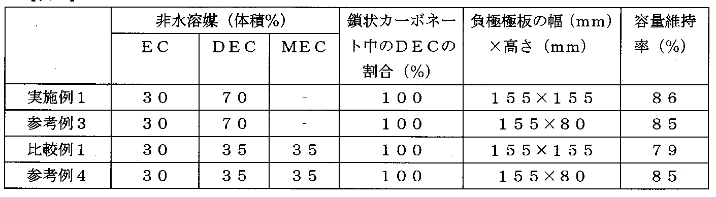
- Examples 1 to 5 in which the proportion of the linear carbonate in the non-aqueous solvent is 50% by volume and the proportion of DEC in the linear carbonate is 70% by volume or more, the capacity retention rate is as high as 84 to 86%. Value.
- Comparative Example 1 in which the proportion of DEC in the chain carbonate was 50% by volume, the capacity retention rate was a low value of 79%.
- the amount of Li in the positive electrode active material (the molar ratio of Li in the composition formula) is 1.06 or more, and the amount of Ni in the positive electrode active material (the molar ratio of Ni in the composition formula) is 0.3 to 0.6
- the capacity retention rate was as high as 85 to 87%.
- Comparative Example 3 where the amount of Li in the positive electrode active material was 1.03, the capacity retention rate was a low value of 79%.
- Table 3 shows that the positive electrode active material is Li 1.10 (Ni 0.3 Co 0.4 Mn 0.3 ) O 2 , high temperature cycle for Example 1, Comparative Example 1, Reference Examples 1 and 2. The result of a test is shown. Comparing Reference Example 1 and Reference Example 2, it can be seen that a cylindrical lithium ion battery using a wound electrode body does not affect the high-temperature cycle characteristics even if the composition of the nonaqueous solvent is different. Moreover, also in Reference Example 2 in which the proportion of DEC in the chain carbonate was 50% by volume, the capacity retention rate was a relatively high value of 82%.
- the gas generated inside the electrode body due to the high temperature cycle is easily released outside the electrode body as compared with the stacked electrode body using a large-area electrode plate, and is due to the charge / discharge cycle under high temperature conditions. It is considered that the capacity drop is small. From this, it can be seen that the decrease in capacity due to the charge / discharge cycle under high temperature conditions is a problem peculiar to the non-aqueous electrolyte secondary battery provided with the laminated electrode body using a large-area electrode plate.
- a non-aqueous electrolyte secondary battery using a wound electrode body has a problem that it is difficult to obtain a large-capacity battery.
- Table 4 shows that the positive electrode active material is Li 1.10 (Ni 0.3 Co 0.4 Mn 0.3 ) O 2 , high temperature cycle test for Example 1, Comparative Example 1, Reference Examples 3 and 4. The results are shown. From Table 4, when the height of the negative electrode plate is 80 mm, the composition of the non-aqueous solvent has little effect on the capacity retention rate, whereas when the width and height of the negative electrode plate are both 155 mm, It can be seen that the composition of the aqueous solvent greatly affects the capacity retention rate. From this, the problem of capacity reduction due to charge / discharge cycles under high temperature conditions is a problem peculiar to non-aqueous electrolyte secondary batteries including a laminated electrode body using a large-area electrode plate whose width and height are both 100 mm or more. It is thought that. If the length of one side of the electrode plate is smaller than 100 mm, it is difficult to obtain a large capacity secondary battery.
- a positive electrode plate and a negative electrode having a large area can be obtained by using a lithium transition metal composite oxide having a specific composition as a positive electrode active material and using a nonaqueous electrolyte containing a nonaqueous solvent having a specific composition. Even a non-aqueous electrolyte secondary battery including a laminated electrode body in which electrode plates are laminated can provide a non-aqueous electrolyte secondary battery having excellent high-temperature cycle characteristics.
- the negative electrode active material graphite, graphitized pitch-based carbon fiber, non-graphitizable carbon, graphitizable carbon, pyrolytic carbon, glassy carbon, organic polymer compound fired body, carbon fiber , Activated carbon, coke, tin oxide, silicon, silicon oxide, and mixtures thereof can be used.
- non-aqueous solvent of the non-aqueous electrolyte carbonates, lactones, ethers, ketones, esters, etc. that have been generally used in non-aqueous electrolyte secondary batteries can be used. It is possible to use a mixture of two or more of these nonaqueous solvents. In particular, it is preferable to use a mixture of a cyclic carbonate such as ethylene carbonate, propylene carbonate, or butylene carbonate and a chain carbonate such as dimethyl carbonate, ethyl methyl carbonate, or diethyl carbonate. Also, an unsaturated cyclic carbonate such as vinylene carbonate (VC) can be added to the non-aqueous electrolyte.
- VC vinylene carbonate
- the electrolyte salt of the nonaqueous electrolyte those generally used as the electrolyte salt in the conventional lithium ion secondary battery can be used.
- LiPF 6 LiBF 4 , LiCF 3 SO 3 , LiN (CF 3 SO 2 ) 2 , LiN (C 2 F 5 SO 2 ) 2 , LiN (CF 3 SO 2 ) (C 4 F 9 SO 2 ), LiC (CF 3 SO 2 ) 3 , LiC (C 2 F 5 SO 2 ) 3 , LiAsF 6 , LiClO 4 , Li 2 B 10 Cl 10 , Li 2 B 12 Cl 12 , LiB (C 2 O 4 ) 2 , LiB ( C 2 O 4 ) F 2 , LiP (C 2 O 4 ) 3 , LiP (C 2 O 4 ) 2 F 2 , LiP (C 2 O 4 ) F 4 and the like and mixtures thereof are used.
- LiPF 6 is particularly preferable.
- a metal exterior can be used as the exterior body in addition to the laminate exterior body.
- a metal sheet having a resin layer formed on the surface thereof can be used.
- aluminum, aluminum alloy, stainless steel, etc. as the metal layer
- polyethylene, polypropylene, etc. as the inner layer (battery inner side)
- nylon, polyethylene terephthalate (PET), PET / nylon laminated film, etc. as the outer layer (battery outer side) What is comprised using is mentioned.
- SYMBOLS 1 Laminate exterior body, 1 '... welding sealing part, 2 ... positive electrode plate, 3 ... negative electrode plate, 4 ... positive electrode current collection tab, 5 ... negative electrode current collection Tab, 6 ... Positive electrode terminal, 7 ... Negative electrode terminal, 8 ... Positive electrode tab resin, 9 ... Negative electrode tab resin, 10 ... Multilayer electrode body, 11 ... Insulating tape, 12. ⁇ Insulating sheet, 13 ⁇ Exterior can, 14 ⁇ Positive electrode plate, 14a ⁇ Positive electrode lead, 15 ⁇ Negative electrode plate, 15a ⁇ Negative electrode lead, 16 ⁇ Separator, 17 ⁇ ..Sealing body, 18 ... insulating packing, 30 ... cylindrical lithium ion battery
Landscapes
- Chemical & Material Sciences (AREA)
- Chemical Kinetics & Catalysis (AREA)
- Electrochemistry (AREA)
- General Chemical & Material Sciences (AREA)
- Inorganic Chemistry (AREA)
- Engineering & Computer Science (AREA)
- Manufacturing & Machinery (AREA)
- Physics & Mathematics (AREA)
- Condensed Matter Physics & Semiconductors (AREA)
- General Physics & Mathematics (AREA)
- Materials Engineering (AREA)
- Secondary Cells (AREA)
- Battery Electrode And Active Subsutance (AREA)
- Sealing Battery Cases Or Jackets (AREA)
Description
〔正極極板の作製〕
正極活物質としてのLi1.10(Ni0.3Co0.4Mn0.3)O2を94質量%と、導電剤としてのカーボンブラックを3質量%と、結着剤としてのポリフッ化ビニリデン(PVdF)を3質量%と、溶剤としてのN-メチル-2-ピロリドン(NMP)溶液とを混合して正極合剤スラリーを調製した。この正極合剤スラリーを、正極芯体としてのアルミニウム箔(厚み:20μm)の両面にドクターブレード法により塗布した。その後、加熱することにより溶剤を除去し、ローラーで厚み0.2mmにまで圧縮した後、図2Aに示すように幅L1=150mm、高さL2=150mmになるように切断して、両面に正極活物質層2aを有する正極極板2を作製した。この際、正極極板2の端部から幅L3=30mm、高さL4=20mmの正極活物質層2aが形成されていない正極芯体を延出させて正極集電タブ4とした。
負極活物質としての黒鉛を98質量%と、カルボキシメチルセルロース(CMC)を1質量%と、スチレンブタジエンゴム(SBR)を1質量%と、水とを混合することにより負極合剤スラリーを得た。その後、この負極合剤スラリーを、負極芯体としての銅箔(厚み:10μm)の両面にドクターブレード方により塗布した。その後、加熱することにより水を除去し、ローラーで厚み0.2mmにまで圧縮した後、図2Bに示すように、幅L6=155mm、高さL6=155mmになるように切断して、両面に負極活物質層3aを有する負極極板3を作製した。この際、負極極板の端部から幅L7=30mm、高さL8=20mmの負極活物質層3aが形成されていない負極芯体を延出させて負極集電タブ5とした。
エチレンカーボネート(EC)とジエチルカーボネート(DEC)を体積比で30:70の割合で混合した非水溶媒に、LiPF6を1.2mol/Lの濃度で溶解し、ビニレンカーボネート(VC)を非水溶媒に対して3.0質量%添加し、非水電解液を作製した。なお、本発明における非水溶媒中の各溶媒の体積比は、25℃、1気圧の条件下における比率である。
上記の方法で作製した正極極板2を20枚と、上記の方法で作成した負極極板3を21枚とを、ポリエチレン製微多孔膜セパレータ(155mm×155mm、厚さ20μm)を介して交互に積層し積層型電極体10を作製した。なお、積層型電極体10においては、最外側両面に負極極板3を配置し、さらにその外側両面に絶縁シート12を配置し、絶縁テープ11により固定した。
各正極極板2の正極集電タブ4を一つに束ね、幅30mm、高さ50mm、厚み0.4mmのアルミニウム板よりなる正極端子6に超音波溶接法により接合した。また、各負極極板3の負極集電タブ5を一つに束ね、幅30mm、長さ50mm、厚み0.4mmの銅板よりなる負極端子7に超音波溶接法により接合した。ここで、正極端子6及び負極端子7にはそれぞれ正極タブ樹脂8及び負極タブ樹脂9が接着されている。正極タブ樹脂8及び負極タブ樹脂9は後述するように正極端子6及び負極端子7とラミネート外装体1の間にそれぞれ介在し、正極端子6及び負極端子7とラミネート外装体1の接着性を向上させることにより、ラミネート外装体1の封止性を向上させる。
あらかじめ電極体が設置できるようにカップ状に成形したラミネート外装体1に、上記の方法で作製した積層型電極体10を挿入し、正極端子6及び負極端子7のみがラミネート外装体1より外部に突出するようにして、正極端子6及び負極端子7がある辺を除く3辺のうち1辺を残し、3辺を熱融着した。ここで、正極タブ樹脂8及び負極タブ樹脂9は、正極端子6及び負極端子7とラミネート外装体の間にそれぞれ介在する状態となる。
上記ラミネート外装体1の熱溶着していない1辺から、上記の方法で調製した非水電解液を注入した。その後、ラミネート外装体1の内部が減圧状態(90kPa)になるようにして、ラミネート外装体1における熱溶着していない1辺を熱溶着して、実施例1のリチウムイオン電池とした。
非水電解液として、ECとDECを体積比で20:80の割合で混合した非水溶媒に、LiPF6を1.2mol/Lの濃度で溶解し、VCを非水溶媒に対して3.0質量%添加した非水電解液を用いたこと以外は実施例1と同様の方法でリチウムイオン電池を作製し、実施例2のリチウムイオン電池とした。
非水電解液として、EC、DEC、メチルエチルカーボネート(MEC)を体積比で30:49:21の割合で混合した非水溶媒に、LiPF6を1.2mol/Lの濃度で溶解し、VCを非水溶媒に対して3.0質量%添加した非水電解液を用いたこと以外は実施例1と同様の方法でリチウムイオン電池を作製し、実施例3のリチウムイオン電池とした。
非水電解液として、EC、プロピレンカーボネート(PC)、DECを体積比で20:10:70の割合で混合した非水溶媒に、LiPF6を1.2mol/Lの濃度で溶解し、VCを非水溶媒に対して3.0質量%添加した非水電解液を用いたこと以外は実施例1と同様の方法でリチウムイオン電池を作製し、実施例4のリチウムイオン電池とした。
非水電解液として、EC、DECを体積比で50:50の割合で混合した非水溶媒に、LiPF6を1.2mol/Lの濃度で溶解し、VCを非水溶媒に対して3.0質量%添加した非水電解液を用いたこと以外は実施例1と同様の方法でリチウムイオン電池を作製し、実施例5のリチウムイオン電池とした。
非水電解液として、EC、DEC、MECを体積比で30:35:35の割合で混合した非水溶媒に、LiPF6を1.2mol/Lの濃度で溶解し、VCを非水溶媒に対して3.0質量%添加した非水電解液を用いたこと以外は実施例1と同様の方法でリチウムイオン電池を作製し、比較例1のリチウムイオン電池とした。
非水電解液として、ECとDECを体積比で60:40の割合で混合した非水溶媒に、LiPF6を1.2mol/Lの濃度で溶解し、VCを非水溶媒に対して3.0質量%添加した非水電解質を用いたこと以外は実施例1と同様の方法でリチウムイオン電池を作製し、比較例2のリチウムイオン電池とした。
正極活物質として、Li1.20(Ni0.3Co0.4Mn0.3)O2を用いたこと以外は実施例1と同様の方法でリチウムイオン電池を作製し、実施例6のリチウムイオン電池とした。
正極活物質として、Li1.06(Ni0.3Co0.4Mn0.3)O2を用いたこと以外は実施例1と同様の方法でリチウムイオン電池を作製し、実施例7のリチウムイオン電池とした。
正極活物質として、Li1.10(Ni0.5Co0.2Mn0.3)O2を用いたこと以外は実施例1と同様の方法でリチウムイオン電池を作製し、実施例8のリチウムイオン電池とした。
正極活物質として、Li1.10(Ni0.6Co0.2Mn0.2)O2を用いたこと以外は実施例1と同様の方法でリチウムイオン電池を作製し、実施例9のリチウムイオン電池とした。
正極活物質として、Li1.10(Ni0.6Co0.1Mn0.3)O2を用いたこと以外は実施例1と同様の方法でリチウムイオン電池を作製し、実施例10のリチウムイオン電池とした。
正極活物質として、Li1.03(Ni0.3Co0.4Mn0.3)O2を用いたこと以外は実施例1と同様の方法でリチウムイオン電池を作製し、比較例3のリチウムイオン電池とした。
正極活物質として、Li1.10(Ni0.8Co0.2)O2を用いたこと以外は実施例1と同様の方法でリチウムイオン電池を作製し、比較例3のリチウムイオン電池とした。
正極活物質として、Li1.10(Ni0.8Co0.1Mn0.1)O2を用いたこと以外は実施例1と同様の方法でリチウムイオン電池を作製し、比較例5のリチウムイオン電池とした。
正極活物質として、Li1.10(Ni0.2Co0.8)O2を用いたこと以外は実施例1と同様の方法でリチウムイオン電池を作製し、比較例6のリチウムイオン電池とした。
幅及び高さが異なることを除いて実施例1と同様の方法で作製した正極極板及び負極極板を用いて、巻回型電極体(巻回数:21)を作製し、円筒形リチウムイオン電池を作製して参考例1のリチウムイオン電池とした。正極極板は、幅及び高さがそれぞれ56mm、590mmの長尺状のものを用い、負極極板は、幅及び高さがそれぞれ60mm、600mmの長尺状のものを用いた。この円筒形リチウムイオン電池30は図4に示すように、長尺状の正極極板14と長尺状の負極極板15とを、長尺状のセパレータ16を介して巻回した巻回型電極体を、実施例1で調整した非水電解液と共に有底筒状の外装缶13の内部に収納している。外装缶13の開口部は、封口体17により封止され、外装缶13と封口体17の間には絶縁パッキング18が介在し、外装缶13と封口体17は電気的に絶縁されている。正極極板14に接続された正極リード14aが封口体17に接続され、封口体17が正極端子の役割を果たす。また、負極極板15に接続された負極リード15aが外装缶13に接続され、外装缶13が負極端子の役割を果たす。
非水電解液として、EC、DEC、MECを体積比で30:35:35の割合で混合した非水溶媒に、LiPF6を1.2mol/Lの濃度で溶解し、VCを非水溶媒に対して3.0質量%添加した非水電解液を用いたこと以外は参考例1と同様の方法でリチウムイオン電池を作製し、参考例2のリチウムイオン電池とした。
正極極板2の幅及び高さを150mm×75mmとし、負極極板3の幅及び高さを155mm×80mmとしたこと以外は実施例1と同様の方法でリチウムイオン電池を作製し、参考例3のリチウムイオン電池とした。
正極極板2の幅及び高さを150mm×75mmとし、負極極板3の幅及び高さを155mm×80mmとしたこと以外は比較例1と同様の方法でリチウムイオン電池を作製し、参考例4のリチウムイオン電池とした。
実施例1~10、比較例1~6、参考例1~4のリチウムイオン電池について、50℃の温度条件下で定電流充電(1C、終止電圧4.2V)‐定電圧充電(電圧4.2V、終止電流1/50C)後、電流値2Cレートで3.0Vまで放電した。これを1サイクル目の充放電とした。ついで、このような充放電を400サイクル繰り返して行い、1サイクル目の放電容量に対する400サイクル目の放電容量の比率(%)を、容量維持率(%)とした。
容量維持率(%)=(400サイクル目の放電容量/1サイクル目の放電容量)×100


Claims (7)
- 正極芯体の表面に正極活物質層が形成された方形状の正極極板と、負極芯体の表面に負極活物質層が形成された方形状の負極極板とをセパレータを介して積層した積層型電極体を非水電解質と共に外装体に収納した非水電解質二次電池であって、
前記正極極板の幅及び高さがそれぞれ100mm以上であり、前記負極極板の幅及び高さがそれぞれ100mm以上であり、前記積層型電極体は10枚以上の前記正極極板と10枚以上の前記負極極板をセパレータを介して積層したものであり、
前記正極活物質層は、正極活物質としてLia(NibCocMnd)MeO2(ここで、1.05≦a≦1.20、0.3≦b≦0.6、b+c+d=1、0≦e≦0.05、M=Ti、Nb、Mo、Zn、Al、Sn、Mg、Ca、Sr、Zr、Wよりなる群から選択される少なくとも1種の元素)で表されるリチウム遷移金属複合酸化物を含有し、
前記非水電解質は非水溶媒及び電解質塩を含有し、前記非水溶媒に含有される鎖状カーボネートの割合が前記非水溶媒に対して50体積%以上であり、前記鎖状カーボネートに含有されるジエチルカーボネートの割合が前記鎖状カーボネートに対して70体積%以上である非水電解質二次電池。 - 前記鎖状カーボネートが、ジメチルカーボネート、ジエチルカーボネート、及びメチルエチルカーボネートからなる群から選ばれる少なくとも1種である請求項1に記載の非水電解質二次電池。
- 前記リチウム遷移金属複合酸化物がLia(NibCocMnd)MeO2(ここで、1.05≦a≦1.20、0.3≦b≦0.6、0<c、0<d、b+c+d=1、0≦e≦0.05、M=Ti、Nb、Mo、Zn、Al、Sn、Mg、Ca、Sr、Zr、Wよりなる群から選択される少なくとも1種の元素)で表されるリチウム遷移金属複合酸化物である請求項1又は2に記載の非水電解質二次電池。
- 前記リチウム遷移金属複合酸化物がLia(NibCocMnd)MeO2(ここで、1.05≦a≦1.20、0.3≦b≦0.6、0<c、0<d、b+c+d=1、0<e≦0.05、M=Ti、Nb、Mo、Zn、Al、Sn、Mg、Ca、Sr、Zr、Wよりなる群から選択される少なくとも1種の元素)で表されるリチウム遷移金属複合酸化物である請求項1又は2に記載の非水電解質二次電池。
- 前記負極活物質層は、ゴム系結着材を含有する請求項1~4のいずれかに記載の非水電解質二次電池。
- 前記非水電解質が、ビニレンカーボネートを前記非水溶媒に対して0.5~4.0質量%含有する請求項1~5のいずれかに記載の非水電解質二次電池。
- 前記外装体は金属箔の両面に樹脂層が形成されたラミネート材からなり、前記外装体が減圧状態で封止されている請求・BR> 1~6のいずれかに記載の非水電解質二次電池。
Priority Applications (3)
| Application Number | Priority Date | Filing Date | Title |
|---|---|---|---|
| JP2014504947A JP6070691B2 (ja) | 2012-03-15 | 2013-03-13 | 非水電解質二次電池 |
| CN201380013883.3A CN104170155A (zh) | 2012-03-15 | 2013-03-13 | 非水电解质二次电池 |
| US14/378,519 US20150030911A1 (en) | 2012-03-15 | 2013-03-13 | Non-aqueous electrolyte secondary battery |
Applications Claiming Priority (2)
| Application Number | Priority Date | Filing Date | Title |
|---|---|---|---|
| JP2012058060 | 2012-03-15 | ||
| JP2012-058060 | 2012-03-15 |
Publications (1)
| Publication Number | Publication Date |
|---|---|
| WO2013137285A1 true WO2013137285A1 (ja) | 2013-09-19 |
Family
ID=49161191
Family Applications (1)
| Application Number | Title | Priority Date | Filing Date |
|---|---|---|---|
| PCT/JP2013/056903 Ceased WO2013137285A1 (ja) | 2012-03-15 | 2013-03-13 | 非水電解質二次電池 |
Country Status (4)
| Country | Link |
|---|---|
| US (1) | US20150030911A1 (ja) |
| JP (1) | JP6070691B2 (ja) |
| CN (1) | CN104170155A (ja) |
| WO (1) | WO2013137285A1 (ja) |
Families Citing this family (5)
| Publication number | Priority date | Publication date | Assignee | Title |
|---|---|---|---|---|
| US10868299B2 (en) * | 2016-10-31 | 2020-12-15 | Panasonic Intellectual Property Management Co., Ltd. | Non-aqueous electrolyte secondary battery |
| KR102630774B1 (ko) | 2016-12-29 | 2024-01-30 | 매직 립, 인코포레이티드 | 외부 조건들에 기초한 웨어러블 디스플레이 디바이스의자동 제어 |
| US11646438B2 (en) | 2017-01-24 | 2023-05-09 | Sanyo Electric Co., Ltd. | Method of manufacturing electrode plate for battery, method of manufacturing battery, and battery |
| CN111952581A (zh) * | 2020-08-25 | 2020-11-17 | 湖北融通高科先进材料有限公司 | Ncm613单晶型正极材料及其制备方法 |
| US20250239602A1 (en) * | 2024-01-23 | 2025-07-24 | Priyadarshi Panda | Li ion product for accessible energy density optimization |
Citations (7)
| Publication number | Priority date | Publication date | Assignee | Title |
|---|---|---|---|---|
| JPH10208747A (ja) * | 1997-01-29 | 1998-08-07 | Hitachi Ltd | 二次電池および二次電池を利用した組電池と機器システム |
| JPH10261440A (ja) * | 1997-03-19 | 1998-09-29 | Hitachi Ltd | リチウム二次電池とその製造方法および電池システム |
| JPH11162510A (ja) * | 1997-11-27 | 1999-06-18 | Toray Ind Inc | 非水電解液二次電池 |
| WO2002040404A1 (en) * | 2000-11-16 | 2002-05-23 | Hitachi Maxell, Ltd. | Lithium-containing composite oxide and nonaqueous secondary cell using the same, and method for manufacturing the same |
| JP2006202702A (ja) * | 2005-01-24 | 2006-08-03 | Hitachi Maxell Ltd | 非水電解質二次電池 |
| JP2009187675A (ja) * | 2008-02-01 | 2009-08-20 | Sharp Corp | 積層型二次電池およびその製造方法 |
| JP2011071103A (ja) * | 2009-08-25 | 2011-04-07 | Toshiba Corp | 正極、非水電解質電池及び電池パック |
Family Cites Families (4)
| Publication number | Priority date | Publication date | Assignee | Title |
|---|---|---|---|---|
| WO1999060652A1 (en) * | 1998-05-20 | 1999-11-25 | Osaka Gas Company Limited | Nonaqueous secondary cell and method for controlling the same |
| US20090197160A1 (en) * | 2008-01-31 | 2009-08-06 | Sanyo Electric Co., Ltd. | Stack type battery |
| SI2230350T1 (sl) * | 2009-03-18 | 2011-07-29 | Baumhueter Extrusion Gmbh | Polimerno vlakno, njegova uporaba in postopek za njegovo izdelavo |
| KR101363443B1 (ko) * | 2009-06-17 | 2014-02-14 | 히다치 막셀 가부시키가이샤 | 전기 화학 소자용 전극 및 그것을 사용한 전기 화학 소자 |
-
2013
- 2013-03-13 CN CN201380013883.3A patent/CN104170155A/zh active Pending
- 2013-03-13 US US14/378,519 patent/US20150030911A1/en not_active Abandoned
- 2013-03-13 JP JP2014504947A patent/JP6070691B2/ja active Active
- 2013-03-13 WO PCT/JP2013/056903 patent/WO2013137285A1/ja not_active Ceased
Patent Citations (7)
| Publication number | Priority date | Publication date | Assignee | Title |
|---|---|---|---|---|
| JPH10208747A (ja) * | 1997-01-29 | 1998-08-07 | Hitachi Ltd | 二次電池および二次電池を利用した組電池と機器システム |
| JPH10261440A (ja) * | 1997-03-19 | 1998-09-29 | Hitachi Ltd | リチウム二次電池とその製造方法および電池システム |
| JPH11162510A (ja) * | 1997-11-27 | 1999-06-18 | Toray Ind Inc | 非水電解液二次電池 |
| WO2002040404A1 (en) * | 2000-11-16 | 2002-05-23 | Hitachi Maxell, Ltd. | Lithium-containing composite oxide and nonaqueous secondary cell using the same, and method for manufacturing the same |
| JP2006202702A (ja) * | 2005-01-24 | 2006-08-03 | Hitachi Maxell Ltd | 非水電解質二次電池 |
| JP2009187675A (ja) * | 2008-02-01 | 2009-08-20 | Sharp Corp | 積層型二次電池およびその製造方法 |
| JP2011071103A (ja) * | 2009-08-25 | 2011-04-07 | Toshiba Corp | 正極、非水電解質電池及び電池パック |
Also Published As
| Publication number | Publication date |
|---|---|
| CN104170155A (zh) | 2014-11-26 |
| US20150030911A1 (en) | 2015-01-29 |
| JPWO2013137285A1 (ja) | 2015-08-03 |
| JP6070691B2 (ja) | 2017-02-01 |
Similar Documents
| Publication | Publication Date | Title |
|---|---|---|
| JP2013201077A (ja) | 非水電解質二次電池 | |
| JP5246747B2 (ja) | リチウムイオン二次電池用負極、およびそれを用いたリチウムイオン二次電池 | |
| US20140178724A1 (en) | Nonaqueous electrolyte battery and battery pack | |
| JP2019016483A (ja) | 非水電解質二次電池 | |
| JP6424426B2 (ja) | 組電池 | |
| US12249720B2 (en) | Electrode assembly having enhanced safety and lithium secondary battery comprising same | |
| WO2019098056A1 (ja) | リチウムイオン二次電池 | |
| JP6165425B2 (ja) | 非水電解質二次電池及びその製造方法 | |
| US20150037663A1 (en) | Battery cell having double sealing structure | |
| JP2016035900A (ja) | 非水電解質電池及び電池パック | |
| CN108432023A (zh) | 二次电池及其制造方法 | |
| US20220294015A1 (en) | Nonaqueous electrolyte secondary battery | |
| WO2016013179A1 (ja) | 非水電解質二次電池 | |
| US20150263334A1 (en) | Non-aqueous electrolyte secondary battery | |
| JP6275694B2 (ja) | 非水電解質二次電池 | |
| CN107836061B (zh) | 非水电解质电池及电池包 | |
| KR102520421B1 (ko) | 부극 | |
| JP6070691B2 (ja) | 非水電解質二次電池 | |
| US9356312B2 (en) | Method for preparing secondary battery and the secondary battery prepared by using the same | |
| WO2020137818A1 (ja) | 非水電解質二次電池及びその製造方法 | |
| JP6287186B2 (ja) | 非水電解質二次電池 | |
| US20130078497A1 (en) | Nonaqueous electrolyte secondary battery | |
| JP2018190624A (ja) | 非水電解質二次電池 | |
| JP2014035892A (ja) | 非水電解質二次電池 | |
| JP2013206724A (ja) | 非水電解質二次電池 |
Legal Events
| Date | Code | Title | Description |
|---|---|---|---|
| 121 | Ep: the epo has been informed by wipo that ep was designated in this application |
Ref document number: 13761115 Country of ref document: EP Kind code of ref document: A1 |
|
| ENP | Entry into the national phase |
Ref document number: 2014504947 Country of ref document: JP Kind code of ref document: A |
|
| WWE | Wipo information: entry into national phase |
Ref document number: 14378519 Country of ref document: US |
|
| NENP | Non-entry into the national phase |
Ref country code: DE |
|
| 122 | Ep: pct application non-entry in european phase |
Ref document number: 13761115 Country of ref document: EP Kind code of ref document: A1 |