WO2013137256A1 - 等速自在継手用外側継手部材の製造方法および外側継手部材 - Google Patents
等速自在継手用外側継手部材の製造方法および外側継手部材 Download PDFInfo
- Publication number
- WO2013137256A1 WO2013137256A1 PCT/JP2013/056816 JP2013056816W WO2013137256A1 WO 2013137256 A1 WO2013137256 A1 WO 2013137256A1 JP 2013056816 W JP2013056816 W JP 2013056816W WO 2013137256 A1 WO2013137256 A1 WO 2013137256A1
- Authority
- WO
- WIPO (PCT)
- Prior art keywords
- cup
- joint member
- forging
- outer joint
- velocity universal
- Prior art date
- Legal status (The legal status is an assumption and is not a legal conclusion. Google has not performed a legal analysis and makes no representation as to the accuracy of the status listed.)
- Ceased
Links
Images
























Classifications
-
- F—MECHANICAL ENGINEERING; LIGHTING; HEATING; WEAPONS; BLASTING
- F16—ENGINEERING ELEMENTS AND UNITS; GENERAL MEASURES FOR PRODUCING AND MAINTAINING EFFECTIVE FUNCTIONING OF MACHINES OR INSTALLATIONS; THERMAL INSULATION IN GENERAL
- F16D—COUPLINGS FOR TRANSMITTING ROTATION; CLUTCHES; BRAKES
- F16D3/00—Yielding couplings, i.e. with means permitting movement between the connected parts during the drive
- F16D3/16—Universal joints in which flexibility is produced by means of pivots or sliding or rolling connecting parts
- F16D3/20—Universal joints in which flexibility is produced by means of pivots or sliding or rolling connecting parts one coupling part entering a sleeve of the other coupling part and connected thereto by sliding or rolling members
- F16D3/202—Universal joints in which flexibility is produced by means of pivots or sliding or rolling connecting parts one coupling part entering a sleeve of the other coupling part and connected thereto by sliding or rolling members one coupling part having radially projecting pins, e.g. tripod joints
- F16D3/205—Universal joints in which flexibility is produced by means of pivots or sliding or rolling connecting parts one coupling part entering a sleeve of the other coupling part and connected thereto by sliding or rolling members one coupling part having radially projecting pins, e.g. tripod joints the pins extending radially outwardly from the coupling part
- F16D3/2055—Universal joints in which flexibility is produced by means of pivots or sliding or rolling connecting parts one coupling part entering a sleeve of the other coupling part and connected thereto by sliding or rolling members one coupling part having radially projecting pins, e.g. tripod joints the pins extending radially outwardly from the coupling part having three pins, i.e. true tripod joints
-
- B—PERFORMING OPERATIONS; TRANSPORTING
- B21—MECHANICAL METAL-WORKING WITHOUT ESSENTIALLY REMOVING MATERIAL; PUNCHING METAL
- B21C—MANUFACTURE OF METAL SHEETS, WIRE, RODS, TUBES, PROFILES OR LIKE SEMI-MANUFACTURED PRODUCTS OTHERWISE THAN BY ROLLING; AUXILIARY OPERATIONS USED IN CONNECTION WITH METAL-WORKING WITHOUT ESSENTIALLY REMOVING MATERIAL
- B21C51/00—Measuring, gauging, indicating, counting, or marking devices specially adapted for use in the production or manipulation of material in accordance with subclasses B21B - B21F
- B21C51/005—Marking devices
-
- B—PERFORMING OPERATIONS; TRANSPORTING
- B21—MECHANICAL METAL-WORKING WITHOUT ESSENTIALLY REMOVING MATERIAL; PUNCHING METAL
- B21J—FORGING; HAMMERING; PRESSING METAL; RIVETING; FORGE FURNACES
- B21J5/00—Methods for forging, hammering, or pressing; Special equipment or accessories therefor
- B21J5/06—Methods for forging, hammering, or pressing; Special equipment or accessories therefor for performing particular operations
- B21J5/12—Forming profiles on internal or external surfaces
-
- B—PERFORMING OPERATIONS; TRANSPORTING
- B21—MECHANICAL METAL-WORKING WITHOUT ESSENTIALLY REMOVING MATERIAL; PUNCHING METAL
- B21K—MAKING FORGED OR PRESSED METAL PRODUCTS, e.g. HORSE-SHOES, RIVETS, BOLTS OR WHEELS
- B21K1/00—Making machine elements
- B21K1/76—Making machine elements elements not mentioned in one of the preceding groups
- B21K1/762—Coupling members for conveying mechanical motion, e.g. universal joints
- B21K1/765—Outer elements of coupling members
-
- F—MECHANICAL ENGINEERING; LIGHTING; HEATING; WEAPONS; BLASTING
- F16—ENGINEERING ELEMENTS AND UNITS; GENERAL MEASURES FOR PRODUCING AND MAINTAINING EFFECTIVE FUNCTIONING OF MACHINES OR INSTALLATIONS; THERMAL INSULATION IN GENERAL
- F16D—COUPLINGS FOR TRANSMITTING ROTATION; CLUTCHES; BRAKES
- F16D3/00—Yielding couplings, i.e. with means permitting movement between the connected parts during the drive
- F16D3/16—Universal joints in which flexibility is produced by means of pivots or sliding or rolling connecting parts
- F16D3/20—Universal joints in which flexibility is produced by means of pivots or sliding or rolling connecting parts one coupling part entering a sleeve of the other coupling part and connected thereto by sliding or rolling members
- F16D3/22—Universal joints in which flexibility is produced by means of pivots or sliding or rolling connecting parts one coupling part entering a sleeve of the other coupling part and connected thereto by sliding or rolling members the rolling members being balls, rollers, or the like, guided in grooves or sockets in both coupling parts
- F16D3/223—Universal joints in which flexibility is produced by means of pivots or sliding or rolling connecting parts one coupling part entering a sleeve of the other coupling part and connected thereto by sliding or rolling members the rolling members being balls, rollers, or the like, guided in grooves or sockets in both coupling parts the rolling members being guided in grooves in both coupling parts
-
- F—MECHANICAL ENGINEERING; LIGHTING; HEATING; WEAPONS; BLASTING
- F16—ENGINEERING ELEMENTS AND UNITS; GENERAL MEASURES FOR PRODUCING AND MAINTAINING EFFECTIVE FUNCTIONING OF MACHINES OR INSTALLATIONS; THERMAL INSULATION IN GENERAL
- F16D—COUPLINGS FOR TRANSMITTING ROTATION; CLUTCHES; BRAKES
- F16D2300/00—Special features for couplings or clutches
- F16D2300/12—Mounting or assembling
Definitions
- the present invention is used in, for example, power transmission systems of automobiles, aircraft, ships, various industrial machines, etc., and is an outer joint for a constant velocity universal joint that transmits rotational power at a constant speed between two axes of a driving side and a driven side.
- the present invention relates to a member manufacturing method and an outer joint member.
- constant velocity universal joints are roughly classified into fixed constant velocity universal joints that allow only angular displacement and sliding constant velocity universal joints that allow angular displacement and axial displacement.
- the constant velocity universal joint has a cup portion that is open at one end, and is provided with a plurality of track grooves extending in the axial direction on the inner diameter surface of the cup portion.
- a joint member and joint internal components such as an inner joint member and a torque transmission member housed in the inner periphery of the cup portion are provided as main constituent members.
- the outer joint members are manufactured using various processing methods such as machining represented by cutting and turning and plastic working represented by forging, but the production efficiency and yield are improved. In recent years, plastic working is often employed as much as possible.
- Patent Document 1 discloses an outer joint member of a tripod type constant velocity universal joint, which is a kind of sliding type constant velocity universal joint, in particular, a plurality of tracks having one end opened and extending axially on an inner diameter surface.
- a method of manufacturing an outer joint member integrally including a bottomed cylindrical cup portion provided with a groove and a shaft portion extending axially outward from the other end of the cup portion by plastic working is described. .
- a forging process in which a rod-shaped material is formed into an intermediate forged product having a cup-shaped portion having a track groove roughly formed on the inner diameter surface by upsetting, forward extrusion, backward extrusion, and the like.
- the manufacturing method (procedure) described above produces not only the outer joint member for the sliding type constant velocity universal joint but also the outer joint member for the fixed type constant velocity universal joint represented by the undercut free type. In this case, it can be preferably applied.
- the shape (size of each part) of the final forged product is likely to vary among individuals because of variations in the weight and volume between the rod-shaped materials, among which the opening end of the cup-shaped part is particularly varied. It is a part that tends to appear large. Therefore, before paying out the final forged product to a subsequent process such as a finishing process for turning or grinding, or a heat treatment process for quenching, the open end of the cup-shaped part of the final forged product It is inspected whether or not the portion is molded into a predetermined shape (whether or not the cup depth of the cup-shaped portion is within the tolerance range), and only the acceptable product is paid out to the subsequent process.
- the inspection of whether or not the cup depth is within the tolerance range is performed by, for example, a dedicated measuring instrument 300 as shown in FIG. (A combination of a scale 302 and a jig 301 having a substantially T-shaped cross section composed of an axial portion 301a having an abutting portion and a radial portion 301b having an abutting portion with a cup-shaped inner diameter surface)
- the measurement result was executed by comparing with the dimensional standard for each product.
- the opening end shape of the cup-shaped part in the intermediate forged product or the final forged product is not only the weight and volume of the rod-shaped material, but also the intermediate product obtained in the middle of the pre-forging process (finally the intermediate forged product and Depends on the molding accuracy of the product. Therefore, it is easy to determine and confirm whether or not the intermediate product or intermediate forged product has been formed into a predetermined shape, more specifically, whether or not the workpiece has been appropriately plastically deformed following the forging die used in the pre-forging process. If this is possible, the complicated inspection process can be simplified or omitted, and it is not necessary to bother the intermediate forging product, which is likely to be defective after the ironing process. Can be improved.
- the pre-forging process for obtaining an intermediate forged product is generally performed continuously using a forging device (transfer press) in which a plurality of forging dies are continuously arranged along the feed direction. is there. Therefore, when trying to determine and confirm whether or not the product has been molded into a predetermined shape on the way, that is, whether or not the workpiece has been appropriately plastically deformed following the forging die, the forging device is completely stopped and sampling inspection is performed. Need to run. However, this significantly reduces the productivity of the outer joint member. In addition, if a halfway product that has been extracted from the forging device is re-entered into the forging device, processing defects are likely to occur. Can not. For this reason, even if the halfway product extracted from the forging device is an acceptable product, the halfway product must be discarded, resulting in a decrease in product yield.
- a forging device transfer press
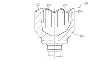
- the opening end surface 402 of the cup-shaped portion 401 of the final forged product 400 is formed on the track groove 403 formation region and the track as shown in FIG.
- the region between the grooves 403 is undulated so as to be convex and concave, and as a result, the required cup depth may not be ensured over the entire circumference.
- Such a problem is caused, for example, by turning a predetermined amount of the open end surface 402 of the cup-shaped portion 401 in which waviness occurs after obtaining an intermediate forged product and eventually a final forged product 400 using a relatively large rod-shaped material. Can be resolved. However, if this is done, the productivity will be reduced because a large end surface finish is essential, and the yield will be reduced because it is necessary to use a larger bar-shaped material than necessary.
- the undulation generated on the open end surface 402 of the cup-shaped portion 401 of the final forged product 400 is such that the thickness reduction rate of the cup-shaped portion of the intermediate forged product due to ironing differs between the circumferential portions of the cup-shaped portion of the intermediate forged product. That is, as shown in FIG. 27 b, it is considered that the main factor is that the thickness of the cup-shaped portion 401 ′ of the intermediate forged product 400 ′ used for ironing is different in each portion in the circumferential direction. Therefore, it is considered that the above problem can be alleviated or eliminated by designing the product so that the difference in thickness between the circumferential portions of the cup portion of the outer joint member is reduced. However, since the thickness of each part in the circumferential direction of the cup portion of the outer joint member is determined in consideration of the function and performance of the constant velocity universal joint, it cannot be easily changed.
- the object of the present invention is to improve the productivity and product yield of the outer joint member which is a constituent member of the constant velocity universal joint, thereby contributing to the cost reduction of the constant velocity universal joint.
- the outer joint member manufacturing method includes a cup portion having one end opened, and a plurality of track grooves extending in the axial direction on the inner diameter surface of the cup portion.
- the outer joint member for a constant velocity universal joint is provided with a cup-shaped portion in which a track groove is roughly formed on an inner diameter surface from a rod-shaped material by performing a plurality of forging processes step by step.
- a determination reference part for enabling visual judgment of pass / fail of the cup depth is molded.
- an outer joint member according to the first invention which has been created to achieve the above object, has a cup portion having one open end, and a plurality of track grooves extending in the axial direction are provided on an inner diameter surface of the cup portion.
- the outer joint member for a constant velocity universal joint, wherein the cup portion is formed by forging, and part or all of the track groove is formed into a finished shape by ironing after forging. It has a judgment reference part for making it possible to visually judge pass / fail of the cup depth, and this judgment reference part is provided by mold forming using a mold used for ironing.
- the cup depth is acceptable, that is, whether or not the cup depth is within the dimensional tolerance, is visually confirmed by the presence / absence of the determination reference portion and the formation mode. It is possible to make a determination with More specifically, if the predetermined reference portion is molded on the molding surface of the cup portion (cup-shaped portion) by ironing, it can be determined that the cup depth is within the tolerance range. Thus, if the determination reference portion is not molded in a predetermined manner on the molding surface of the cup portion (cup-shaped portion) by ironing, it can be determined that the cup depth is not within the tolerance range.
- the determination reference portions can be molded at two locations separated in the axial direction of the cup-shaped portion of the final forged product. That is, when performing the ironing process, it is possible to use a mold that can mold the determination reference portion at two locations separated in the axial direction of the cup-shaped portion of the final forged product.
- the determination reference portion molded on the other end side (the non-opening end portion side) of the cup portion (cup-shaped portion) indicates the tolerance lower limit of the cup depth.
- a judgment reference part molded on one end side (opening end part side) of the cup part (cup-shaped part) can be utilized as a part indicating a tolerance upper limit of the cup depth. After the ironing process is completed, it becomes possible to more accurately determine whether the cup depth is within the tolerance range. More specifically, it can be determined that the cup depth is within the tolerance range if the determination reference portion is molded in a predetermined manner at one axial position of the cup portion (cup-shaped portion). And if the determination reference
- the manufacturing method of the outer joint member which concerns on 1st invention shall further include the edge part removal process which removes the predetermined dimension of the one end part (opening edge part) of the cup-shaped part of a final forging after ironing.
- the end portion of the cup-shaped portion of the final forged product can be removed by reaching the axial position where the entire determination reference portion is removed. That is, the determination reference portion molded by ironing can also be used as a mark when finishing by removing a predetermined dimension in the axial direction from one end of the cup-shaped portion of the final forged product.
- the judgment reference part can take any form as long as it does not hinder the function of the outer joint member.
- it can be provided continuously in the circumferential direction of the cup part (provided over the entire circumference of the cup part), or can be provided intermittently in the circumferential direction of the cup part.
- the determination reference portion is, for example, a step portion having a height difference of 0.01 mm to 1.0 mm, a projecting portion having a height dimension of 0.01 mm to 1.0 mm, or a depth dimension of 0.01 mm or more. It can be composed of a concave portion of 1.0 mm or less.
- the lower limit value of the height difference, height dimension, or depth dimension (hereinafter referred to as “height difference etc.”) of the judgment reference portion is set to 0.01 mm, so that the pass / fail judgment of the cup depth is executed accurately and quickly. For this reason, if the height difference is as small as less than 0.01 mm, there is a high possibility that the pass / fail determination of the cup depth cannot be performed accurately and quickly.
- the upper limit value of the height difference of the determination reference portion is set to 1.0 mm. If the height difference exceeds 1.0 mm, the releasability of the cup-shaped portion and thus the molding accuracy of the cup portion are adversely affected. Because there is a possibility.
- the first invention described above can be applied to an outer joint member in which the track groove is configured only by a linear portion extending in parallel with the joint axis, that is, an outer joint member for a sliding type constant velocity universal joint.
- Examples of applicable sliding constant velocity universal joints include tripod type constant velocity universal joints (TJ) and double offset type constant velocity universal joints (DOJ).
- the track groove is positioned relatively on one end side (opening end portion side) of the cup portion and extends in parallel with the joint axis, and relatively on the other end side of the cup portion ( Applicable to an outer joint member composed of an arcuate portion located on the side opposite the opening), that is, an outer joint member for an undercut-free constant velocity universal joint (UJ), which is a kind of fixed constant velocity universal joint
- UJ undercut-free constant velocity universal joint
- the linear portion of the track groove can be formed into a finished shape by ironing the cup-shaped portion of the intermediate forged product.
- a constant velocity universal joint can be constituted by the outer joint member according to the first invention and the joint internal parts housed in the inner periphery of the cup portion.
- the ironing process may be executed in any atmosphere of cold, warm or hot, but if it is executed cold, it is executed warm or hot. Compared to the case, the molding accuracy of the cup portion (the accuracy of the ironing process) can be improved.
- the manufacturing method of the outer joint member according to the second invention which has been devised to achieve the above object, has a cup portion having one end opened, and a plurality of track grooves extending in the axial direction on the inner diameter surface of the cup portion.
- the outer joint member for a constant velocity universal joint is provided with a cup-shaped portion in which a track groove is roughly formed on an inner diameter surface from a rod-shaped material by performing a plurality of forging processes step by step.
- a mark part is formed so that the pass / fail shape of the cup-shaped part of the intermediate forged product can be visually determined. It is characterized by that.
- the open end of the cup-shaped portion of the intermediate forged product It is possible to easily determine whether or not the portion has been formed into a predetermined shape (whether or not the workpiece has been appropriately plastically deformed following a plurality of forging dies).
- the mark part is formed at the mold part provided in the forging die in the forging process in which poor molding accuracy is likely to occur. If the die is molded, it becomes possible to easily review the molding conditions in the forging process.
- the above configuration can be preferably applied when the forging process using a closed forging die is included in the pre-forging process.
- the closed forging die referred to here is a forging die configured to perform forging in a state where the entire workpiece is sealed in the die. According to the verification by the inventors of the present application, in the forging process stage using the closed forging die, it is particularly easy to cause a forming accuracy defect due to a poor meat filling. Therefore, if the mark part is molded at the forging process stage of the intermediate product by the closed forging die in the pre-forging process, the degree of material satisfaction at this forging process stage is properly grasped, and the outer joint member This is advantageous for improving productivity and product yield.
- an end face mark portion as a mark portion can be molded at a site that becomes an open end face (end face on the opening side) of the cup-shaped portion of the intermediate forged product in the intermediate product.
- the form of the end face mark portion is not particularly limited, and for example, a plurality of shapes may be formed radially, an infinite number of dots may be formed, or an annular shape (one or more) may be formed.
- the mark portion on the portion that becomes the outer diameter surface of the cup-shaped portion of the intermediate forging product may be molded. Further, these mark portions (end face mark portions and outer diameter mark portions) may be formed in a concave shape or may be formed in a convex shape. Whatever form of mark portion is molded, it is desirable that the mark portion has a form that does not adversely affect the operability and the like in consideration of the case where the mark portion remains in the final product.
- the outer joint member according to the second invention which was created to achieve the above object, has a cup portion with one end opened, and a plurality of track grooves extending in the axial direction are provided on the inner diameter surface of the cup portion.
- the mark portion can be provided on the opening side end surface of the cup portion, the outer diameter surface of the cup portion, or both.
- the second invention can also be preferably applied to an outer joint member integrally having a shaft portion extending axially outward from the other end of the cup portion.
- the second invention can be applied to an outer joint member in which a track groove is constituted only by a linear portion, that is, an outer joint member for a sliding type constant velocity universal joint.
- sliding constant velocity universal joints include tripod type constant velocity universal joints (TJ) and double offset type constant velocity universal joints (DOJ).
- TJ tripod type constant velocity universal joints
- DOJ double offset type constant velocity universal joints
- the entire track groove (entire area) can be finished by ironing.
- the track groove is relatively positioned on the linear portion located on one end side (opening end portion side) of the cup portion, and on the other end side (non-opening end portion side) of the cup portion.
- the present invention can also be applied to an outer joint member composed of an arcuate portion positioned, that is, an outer joint member for an undercut-free constant velocity universal joint (UJ) which is a kind of fixed type constant velocity universal joint.
- UJ constant velocity universal joint
- at least a linear portion of the track groove can be finished by ironing.
- a constant velocity universal joint can be configured by the outer joint member according to the second invention described above and the joint internal parts housed in the inner periphery of the cup portion.
- a manufacturing method which has been devised to achieve the above object, has a cup portion that is open at one end, and is provided with a plurality of track grooves extending in the axial direction on the inner diameter surface of the cup portion.
- a method of manufacturing an outer joint member for a constant velocity universal joint which is a pre-forging step for obtaining an intermediate forged product having a cup-shaped portion having a track groove roughly formed on an inner diameter surface from a rod-shaped material, and ironing the intermediate forged product.
- the ironing step to obtain a final forged product having a cup-shaped part with a finished track groove formed on the inner diameter surface, and in the pre-forging process, in the opening end surface of the cup-shaped part of the intermediate forged product,
- the undulation generated on the opening end face of the cup-shaped portion of the final forged product in accordance with the ironing process is characterized in that a concavo-convex shape portion in which the arrangement mode of the concave portion and the convex portion is opposite is molded.
- the degree of undulation that occurs on the opening end face of the final forged product due to the ironing process is reduced without incurring a special increase in processing cost (the difference in height between the concave and convex parts constituting the undulation is reduced. )be able to.
- This makes it possible to improve the productivity by reducing the end face finishing amount (turning amount) of the final forged product, and it is possible to use a rod-like material having a volume that is small enough to reduce the end face finishing amount, Yield can be improved.
- the degree of undulation is greatly reduced, it is possible to omit the end face finishing for the final forged product.
- the productivity and yield of the outer joint member which is one of its constituent members, can be improved without making design changes that affect the function and performance of the constant velocity universal joint. Therefore, it can contribute to the cost reduction of the constant velocity universal joint.
- the cup portion of the outer joint member is generally configured by alternately arranging thin portions and thick portions in the circumferential direction, and the track groove (the bottom surface of the groove) is an inner diameter surface of the thin portion.
- the thickness reduction rate (the amount of axial deformation in the axial direction) associated with the ironing process is larger in the relatively thin portion than in the relatively thick portion. Therefore, in the pre-forging step, an intermediate forged product having a cup-shaped portion in which a circumferential region in which the track groove is roughly formed and a circumferential region in which the concave portion of the concavo-convex shape portion is molded is matched is obtained. Is desirable. Thereby, the amount of waviness of the open end face of the final forged product can be effectively reduced.
- the pre-forging process is generally configured to include a plurality of forging steps. Then, at the final stage (for example, backward extrusion), the concave and convex portion can be molded at the same time as forming the cup-shaped portion having the track groove roughly formed on the inner diameter surface. At this time, the concavo-convex shape portion may be molded by a molding die portion provided in the track groove rough molding punch, or a molding die portion provided in a molding die different from the track groove rough molding punch. You may make it mold by.
- the forging step may be performed in a separate forging step from the molding of the concavo-convex shape portion and the cup-shaped portion having a track groove roughly formed on the inner diameter surface.
- an intermediate forged product having a cup-shaped portion in which track grooves are roughly formed on the inner diameter surface can be obtained in the forging step after molding the uneven portion.
- the third invention can also be preferably applied when manufacturing an outer joint member integrally having a shaft portion extending axially outward from the other end of the cup portion.
- the third invention is an outer joint member in which each track groove is constituted only by a straight portion, for example, a sliding type represented by a tripod type constant velocity universal joint (TJ), a double offset type constant velocity universal joint (DOJ), or the like. It can be applied when manufacturing an outer joint member for a constant velocity universal joint. Further, according to the third aspect of the present invention, each track groove has a linear portion relatively positioned on one end side (opening end portion side) of the cup portion, and relatively the other end side (non-opening end portion side) of the cup portion. Applied when manufacturing an outer joint member composed of an arcuate portion positioned in the outer joint member, for example, an outer joint member for an undercut-free constant velocity universal joint (UJ), which is a kind of fixed constant velocity universal joint. You can also.
- UJ undercut-free constant velocity universal joint
- the present invention it is possible to improve the productivity and product yield of the outer joint member which is a constituent member of the constant velocity universal joint. Thereby, it can contribute to the cost reduction of a constant velocity universal joint.
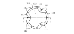
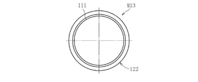
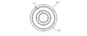
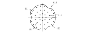
- FIG. 1b is a sectional view taken along line XX in FIG. 1a. It is a schematic front view of the rod-shaped raw material provided to a pre-forging process. It is a schematic front view of the 1st intermediate product. It is a schematic front view of the 2nd halfway product. It is a schematic front view of the 3rd intermediate product. It is a front view of an intermediate forging product. It is sectional drawing which shows a ironing process process typically. It is a schematic sectional drawing of the final forging product which has a cup-shaped part in which the cup depth was less than the tolerance lower limit.
- FIG. 13B is a schematic sectional view taken along line XX in FIG. 13A. It is a top view of the intermediate forging product obtained by performing back extrusion processing to the 3rd intermediate product shown in FIG. 13a.
- FIG. 13C is a schematic cross-sectional view taken along line XX in FIG. 13C. It is a top view of the 3rd intermediate product which was not fabricated by predetermined shape.
- FIG. 14B is a schematic sectional view taken along line XX in FIG. 14A.
- 14b is a plan view of an intermediate forged product obtained by subjecting the third intermediate product shown in FIG. 14a to a backward extrusion process.
- FIG. FIG. 14c is a schematic sectional view taken along line XX in FIG. 14c. It is a top view of the 3rd halfway product concerning other embodiments of the 2nd invention.
- FIG. 15B is a schematic sectional view taken along line XX in FIG. 15A. It is a top view of the 3rd halfway product concerning other embodiments of the 2nd invention.
- FIG. 15C is a schematic sectional view taken along line XX in FIG. 15C.
- FIG. 16B is a schematic sectional view taken along line XX in FIG. 16a. It is a top view of the 3rd halfway product concerning other embodiments of the 2nd invention. It is a top view of the 3rd halfway product concerning other embodiments of the 2nd invention. It is a top view of the 3rd halfway product concerning other embodiments of the 2nd invention. It is a top view of the 3rd halfway product concerning other embodiments of the 2nd invention. It is a top view of the 3rd halfway product concerning other embodiments of the 2nd invention. It is a top view of the 3rd halfway product concerning other embodiments of the 2nd invention. It is a top view of the 3rd halfway product concerning other embodiments of the 2nd invention.
- FIG. 20B is a front view of the intermediate forged product including a cross section taken along line XX in FIG.
- FIG. 20A It is sectional drawing which shows typically a 4th forge process among the pre-forging processes. It is a front view of the final forging product containing a partial cross section. It is sectional drawing which shows the modification of a 4th forge process typically. It is sectional drawing which shows typically the modification of the 3rd forge process of a pre forge process. It is sectional drawing which shows typically the modification of the 4th forge process of a pre-forging process. It is a partial front view of the intermediate forging product which concerns on other embodiment of 3rd invention. It is a partial front view of the intermediate forging product which concerns on other embodiment of 3rd invention. It is a figure which shows typically the mode of the conventional inspection method. It is a side view including the partial cross section of the final forging product of the outer joint member manufactured by the conventional method. FIG. 27B is a front view of the intermediate forged product formed into the final forged product shown in FIG. 27A.
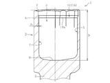
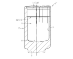
- FIG. 1a shows a schematic front view of an outer joint member 1 for a constant velocity universal joint according to an embodiment of the first invention (hereinafter simply referred to as “outer joint member 1”), and FIG. A schematic sectional view is shown.
- This outer joint member 1 is an outer joint member for a tripod type constant velocity universal joint (TJ) which is a kind of sliding type constant velocity universal joint that allows both angular displacement and axial displacement, and one end is open.
- TJ tripod type constant velocity universal joint
- the bottomed cylindrical cup portion 2 and the shaft portion 3 extending axially outward from the other end of the cup portion 2 are integrally provided.
- the tripod type constant velocity universal joint is configured by incorporating a tripod member as an inner joint member, a roller as a torque transmission member, or the like on the inner periphery of the cup portion 2 of the outer joint member 1.
- Each track groove 5 has a pair of roller guide surfaces 6 and 6 which face each other in the circumferential direction, and is formed in a straight line including the roller guide surfaces 6 and 6 and extending in parallel with the joint axis.
- the axially orthogonal cross section of the cup portion 2 of the present embodiment has a flower crown shape in which three large-diameter portions and three small-diameter portions are alternately arranged in the circumferential direction.
- a track groove 5 is formed on the inner periphery of each large diameter portion.
- the outer joint member 1 is subjected to plastic processing steps such as extrusion processing, upsetting processing, and ironing processing in order to obtain a final forged product 1 ′ having a substantially finished product shape (two-dot chain line in FIG. 4).
- the final forged product 1 ′ is finished by performing an appropriate finishing process and further a heat treatment.
- the entire inner diameter surface 4 of the cup portion 2 including the track groove 5 and the roller guide surface 6 is finished to the final shape by ironing the cup-shaped portion 2 ′ (see FIG. 3) of the intermediate forged product 1 ′′.
- the opening side end surface 7 of the cup portion 2 of the outer joint member 1 of the present embodiment is formed on the cup-shaped portion 2 ′ of the intermediate forged product 1 ′′ as the cup-shaped portion 2 ′ is ironed. It is a surface obtained by freely deforming the opening side end, and is not a surface finished by finishing such as turning.
- the determination reference part is a part that is used as a reference when determining whether or not the cup depth D is within the tolerance range after the ironing process is completed.
- first determination reference part 12 is indicated in parentheses. This determination reference part determines whether or not the cup depth D exceeds the tolerance lower limit (tolerance lower limit of the required cup depth).
- the cup depth D exceeds the upper limit of tolerance (tolerance upper limit of necessary cup depth) on the inner diameter surface 4 of the cup portion 2 as shown in FIG.
- the second determination reference portion 13 serving as a reference is further molded.
- the axis orthogonal plane indicated by reference numeral x1 in FIG. 1b is the tolerance lower limit of the required cup depth, and the bottom of the stepped portion 14 as the first determination reference section 12 for displaying the axis orthogonal plane x1.
- the side end portion 14a is molded according to the axis orthogonal plane x1.
- the entire stepped portion 14 as the first determination reference portion 12 exists on the inner diameter surface 4 of the cup portion 2, which is a molding surface by ironing, and the step as the second determination reference portion 13. Since the portion 14 (see FIG. 5b) does not exist on the inner diameter surface 4 of the cup portion 2, it can be determined by visual confirmation that the cup depth D is within the tolerance range.
- the height difference y1 of the stepped portion 14 serving as the first determination reference portion 12 (and the second determination reference portion 13 shown in FIG. 5b) is set to 0.01 mm or more and 1.0 mm or less.
- the reason why the lower limit of the height difference y1 is set to 0.01 mm is to execute the pass / fail determination of the cup depth D accurately and quickly, and the height difference y1 is so small that it is less than 0.01 mm. And the possibility that the pass / fail determination of the cup depth D cannot be performed accurately and quickly increases.
- the upper limit of the height difference y1 is set to 1.0 mm because if the height difference y1 exceeds 1.0 mm, the mold release property of the cup-shaped part 2 ′ from the molding die used for ironing is adversely affected. This is because there is a possibility that the rolling performance of the roller may be adversely affected.
- the outer joint member 1 includes a pre-forging step (see FIGS. 2a to 2d) for obtaining an intermediate forged product 1 ′′ (see FIG. 3) having a cup-shaped portion 2 ′′, and a cup-shaped portion 2 ′′ of the intermediate forged product 1 ′′.
- Ironing process Fig. 4 for performing ironing process, finishing process for finishing each part of final forged product 1 'obtained through ironing process to final shape, and heat treatment for final forged product 1' finished to final shape It is completed through a heat treatment process.
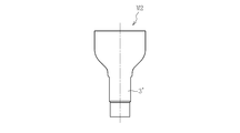
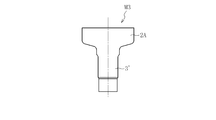
- the pre-forging process consists of multiple forging steps. Specifically, first, a solid bar-shaped material (billet) M shown in FIG. 2a is subjected to forward extrusion processing in the first forging process stage, and as shown in FIG. A first intermediate product M1 is obtained that is rounded and has a central portion of the rod-shaped material M bulged. Next, by further extruding the first intermediate product M1 in the second forging step, the shaft-shaped portion 3 ′ was formed on the side where the outer peripheral edge was rounded, as shown in FIG. 2c. A second intermediate product M2 is obtained. Next, by performing upsetting on the second intermediate product M2 at the third forging step, as shown in FIG. 2d, the third upsetting portion 2A is formed integrally with the shaft-like portion 3 ′. A product M3 is obtained on the way.
- a solid bar-shaped material (billet) M shown in FIG. 2a is subjected to forward extrusion processing in the first forging process stage, and as shown in FIG.
- the track groove 5 ′ roughly formed on the inner diameter surface is formed by performing backward extrusion processing on the upset portion 2 ⁇ / b> A of the third intermediate product M ⁇ b> 3 in the fourth forging step.
- An intermediate forged product 1 ′′ having a cup-shaped portion 2 ′′ having The cup-shaped portion 2 ′′ of the intermediate forged product 1 ′′ has a cross-sectional shape that approximates the cup portion 2 of the outer joint member 1 as a finished product. That is, the cup-shaped portion 2 ′′ of the intermediate forged product 1 ′′ has a corollary cross-sectional shape, and a track groove 5 ′ having roller guide surfaces 6 ′ and 6 ′ is formed on the inner diameter surface thereof.
- the cup-shaped portion 2 ′′ of the intermediate forged product 1 ′′ is thicker and shorter in the axial direction than the cup portion 2 of the outer joint member 1 as a finished product. Therefore, the axial dimension of the track groove 5 ′ is shorter than the axial dimension of the track groove 5.
- the intermediate forged product 1 ′′ is transferred to the ironing process.
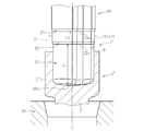
- a cup-shaped intermediate forged product 1 ′′ is formed using a molding die having the ironing punch 20 and the ironing die 30 shown in FIG.
- the part 2 ′′ is ironed and the inner diameter surface of the cup-shaped part 2 ′′ is formed into a finished shape.
- a forming die portion 21 for forming the inner diameter surface of the cup-shaped portion 2 "of the intermediate forged product 1" into a finished shape is provided on the outer periphery of the front end portion of the ironing punch 20, a forming die portion 21 for forming the inner diameter surface of the cup-shaped portion 2 "of the intermediate forged product 1" into a finished shape is provided.
- First and second determination reference molding portions 22 and 23 are provided at two positions spaced apart in the axial direction of the molding die portion 21.
- the first determination standard forming part 22 is inspected / determined whether the cup depth D of the cup part 2 (the cup-shaped part 2 ′ of the final forged product 1 ′) exceeds the tolerance lower limit of the required cup depth. This is a part where the first determination reference part 12 (see FIG. 1b and the like), which serves as a reference when performing, can be molded.
- the second determination reference molding part 23 is a second determination reference part serving as a reference when inspecting / determining whether the cup depth D of the cup part 2 exceeds the upper limit tolerance of the required cup depth.
- 13 (see FIG. 5b) is a part that can be molded. Accordingly, the axial separation distance L1 between the tip surface 20a of the punch 20 and the end 22a of the first determination reference molding portion 22 is equal to the tolerance lower limit value of the cup depth D (required cup depth), and the punch 20 The axial separation distance L2 between the tip surface 20a and the end 23a of the second determination reference molding part 23 is equal to the tolerance upper limit value of the cup depth D (required cup depth).
- the intermediate forged product 1 ′′ is positioned and disposed in the molding die having the above-described configuration, and the iron punch 20 is inserted into the inner periphery of the cup-shaped portion 2 ′′ of the intermediate forged product 1 ′′.
- the ironing die 30 is relatively moved in the axial direction, ironing is performed on the cup-shaped portion 2 ′′ of the intermediate forged product 1 ′′ along with this relative movement.
- the cup shape The portion 2 ′′ extends and deforms in the axial direction, and at the same time, the inner diameter surface of the cup-shaped portion 2 ′′ plastically deforms following the forming die portion 21 of the ironing punch 20.
- the cup-shaped portion 2 ′ of the final forged product 1 ′ is visually confirmed whether or not the cup depth D of the cup portion 2 of the outer joint member 1 as a finished product is within the tolerance range. That is, as shown in FIG.
- the cup depth D is It can be determined that the product is below the tolerance lower limit.
- the cup depth D is the upper limit of tolerance. It can be determined that the product is defective.
- the cup depth D is within the tolerance range when ironing is performed on the cup-shaped portion 2 ′′ of the intermediate forged product 1 ′′ in the ironing process.
- the determination reference part for molding was molded. In this way, whether or not the cup depth D is within the tolerance range is determined based on the determination reference portion (first and first) molded on the inner diameter surface of the cup-shaped portion 2 ′ (cup portion 2). It is possible to make a determination only by visually confirming the presence or absence and the formation mode of the two determination reference parts 12, 13). Therefore, there is no need to perform the measurement / inspection processing of the cup depth D using the dedicated measuring instrument 300 as shown in FIG. 26, and the workability of the measurement / inspection processing can be improved. Can be improved. Thereby, productivity improvement and yield improvement of the outer joint member 1 are achieved.
- the acceptable product determined that the cup depth D is within the dimensional tolerance is paid out to the subsequent process.
- the outer joint member 1 (see FIGS. 1a and 1b) having the cup portion 2 and the shaft portion 3 integrally is completed.
- the outer joint member 1 and the manufacturing method thereof according to one embodiment of the first invention have been described above, but the first invention is not limited to the above-described embodiment and does not depart from the gist of the invention. It is possible to add various changes.
- the determination reference portion (first and second determination reference portions 12 and 13) is constituted by a protruding portion 15 having a height dimension y2 of 0.01 mm or more and 1.0 mm or less, as shown in FIG. 6a.
- the depth dimension y ⁇ b> 3 may be configured by a concave portion 16 having a depth of 0.01 mm or more and 1.0 mm or less.
- 6A and 6B show the case where the protruding portion 15 and the recessed portion 16 as the first determination reference portion 12 are formed over the entire circumference of the inner diameter surface 4 of the cup portion 2 of the outer joint member 1. Illustrated.
- the determination reference portion (first determination reference portion 12 in the illustrated example) may be provided intermittently in the circumferential direction of the cup portion 2.
- the determination reference portion if the determination reference portion is provided in the circumferential region excluding the formation region of the track groove 5, the reduction in rolling performance of the torque transmitting member (roller) due to the provision of the determination reference portion is taken into consideration. Not enough.
- FIG. 7 shows the case where the concave portion 16 is employed as the determination reference portion (first determination reference portion 12), but also when the stepped portion 14 or the protruding portion 15 is employed as the determination reference portion. Such a configuration can be adopted.
- the outer joint member 1 shown in FIG. 1 has an opening of the cup portion 2 on a surface obtained by free deformation of the opening side end portion of the cup-shaped portion 2 ′′ of the intermediate forged product 1 ′′ along with ironing.
- the opening side end surface 7 of the cup portion 2 may be a surface finished by turning as shown in FIG. That is, after the ironing step shown in FIG. 4, a turning step is further provided as an end removing step for removing a predetermined dimension of the opening end of the cup-like portion 2 ′ of the final forged product 1 ′.
- the opening end of the portion 2 ′ may be turned to an axial position where the entire first determination reference portion 12 (stepped portion 14) is removed.
- the stepped portion 14 as the first determination reference portion 12 molded on the inner diameter surface of the cup-shaped portion 2 ′ is a mark indicating the end position of the turning process (formation position of the opening side end surface 7 of the cup portion 2). Can be used as well.
- the determination reference portion is molded on the inner diameter surface 4 of the cup portion 2 (the inner diameter surface of the cup-shaped portion 2 ′ of the final forged product 1 ′).
- the inner diameter surface 4 or in addition to the inner diameter surface 4 of the cup portion 2, it may be molded on the outer diameter surface of the cup portion 2 (not shown).
- the outer joint member 1 for a tripod type constant velocity universal joint (TJ), which is a kind of sliding type constant velocity universal joint, and the case where the first invention is applied when manufacturing the outer joint member 1 are described.
- the first invention is applied to the manufacture of other sliding type constant velocity universal joints, such as an outer joint member for a double offset type constant velocity universal joint (DOJ), and this outer joint member. It is also possible.
- the first invention is not only the outer joint member for the sliding type constant velocity universal joint described above, but also the outer joint for the fixed type constant velocity universal joint such as an undercut free type constant velocity universal joint (UJ). It is also possible to apply when manufacturing a member and this outer joint member.
- the fixed type constant velocity universal joint does not allow axial displacement but allows only angular displacement, and the track groove of the outer joint member incorporated therein is relatively positioned on the cup opening side. It is comprised by the linear part extended in parallel with a joint axis line, and the circular arc-shaped part located in a cup bottom side relatively. In this case, at least a linear portion of the track groove can be finished to a final shape by ironing.
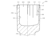
- FIG. 9a shows a schematic plan view of an outer joint member 101 for a constant velocity universal joint according to an embodiment of the second invention (hereinafter simply referred to as “outer joint member 101”), and FIG. A schematic sectional view is shown.
- This outer joint member 101 is an outer joint member for a tripod type constant velocity universal joint (TJ), which is a kind of sliding type constant velocity universal joint that allows both angular displacement and axial displacement, and one end is open.
- the bottomed cylindrical cup portion 102 and the shaft portion 103 extending axially outward from the other end of the cup portion 102 are integrally provided.
- the tripod type constant velocity universal joint is configured by incorporating a tripod member as an inner joint member, a roller as a torque transmission member, or the like on the inner periphery of the cup portion 102 of the outer joint member 101.
- Each track groove 105 has a pair of roller guide surfaces 106 and 106 that face each other in the circumferential direction, and is formed in a straight line including the roller guide surfaces 106 and 106 and extending in parallel with the joint axis.
- the cross section orthogonal to the axis of the cup portion 102 is a flower crown formed by alternately arranging three large-diameter portions and small-diameter portions in the circumferential direction, and a track groove 105 is formed on the inner periphery of each large-diameter portion. Has been. Although not shown in FIGS.
- an inlet chamfer for allowing angular displacement of the joint in the region between the track grooves 105 and 105 on the inner periphery of the opening of the cup portion 102.
- an annular groove for fitting one end portion of the boot is provided at a predetermined position in the axial direction of the outer diameter surface 108 of the cup portion 102.
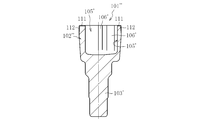
- this outer joint member 101 uses a forging device in which a plurality of forging dies are continuously provided along the feed direction, and is tracked from the rod-shaped material to the inner surface as shown in FIG. 10d.
- a pre-forging step for obtaining an intermediate forged product 101 ′′ having a cup-shaped portion 102 ′′ having a roughly formed groove 105 ′ and ironing of the cup-shaped portion 102 ′′ of the intermediate forged product 101 ′′ are finished on the inner surface.
- An ironing process for obtaining a final forged product 101 ′ see a two-dot chain line in FIG.
- the track groove 105 (the groove bottom surface of the track groove 105 and the pair of roller guide surfaces 106, 106) is entirely cup-shaped portion 102 ′′ of the intermediate forged product 101 ′′ shown in FIG. 10d. It is formed into a finished shape by ironing.
- the open end surface 107 of the cup portion 102 shown in FIGS. 9a and 9b is free to be opened as the cup-shaped portion 102 ′′ of the intermediate forged product 101 ′′ is ironed. It is a surface obtained by deformation (see FIG. 12), and is not a surface finished by machining such as turning, etc. Therefore, although not shown, the opening end surface 107 of the cup portion 102 has a slight amount. There is a swell.
- the cup part 102 has a pass / fail shape of the open end part (the presence or absence of sagging due to the lack of meat in the forging die at the open end part of the cup part 102, and the cup depth extends over the entire circumference of the cup part 102.
- a mark portion is provided for enabling visual determination of whether or not the image is within the tolerance range.
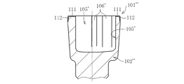
- a plurality of end surface mark portions 111 as mark portions are provided on the opening end surface 107 of the cup portion 102 at predetermined intervals in the circumferential direction, and an outer diameter mark as a mark portion is formed in the opening side region of the outer diameter surface 108 of the cup portion 102.
- a plurality of portions 112 are provided at predetermined intervals in the circumferential direction.
- Each end face mark portion 111 is formed in a groove shape extending radially, and each outer diameter mark portion 112 is formed in a groove shape extending in the axial direction. And since these end surface mark part 111 and the outer diameter mark part 112 are formed in the predetermined mode, the said outer joint member 101 is the dull
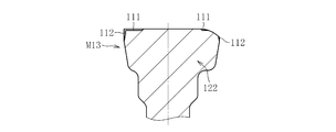
- the third intermediate product M13 which finally becomes the intermediate forged product 101 "and eventually the final forged product 101 '
- sagging may occur due to unsatisfactory meat of the work (second intermediate product M12) on the third forging die for forming the product M13.
- This sagging is illustrated in FIGS. 14c and 14d.
- it remains as it is at the open end (outer peripheral edge portion) of the cup-shaped portion 102 ′′ of the intermediate forged product 101 ′′ obtained by subjecting the third intermediate product M13 to forging (rear extrusion).
- the end face mark portion 111 and the outer diameter mark portion 112 are molded at an intermediate stage of the pre-forging process (in this embodiment, an upsetting process stage using the third forging die 130 shown in FIG. 11). Therefore, the depth dimension of the end face mark portion 111 and the outer diameter mark portion 112 provided in the cup portion 102 of the outer joint member 101 is formed by various processes applied after the both mark portions 111 and 112 are molded. In many cases, it is different from the depth dimension of the mark portions 111 and 112 immediately after the mark.
- the outer joint member 101 includes a pre-forging step for obtaining an intermediate forged product 101 ′′ shown in FIG. 10d, a ironing step for obtaining a final forged product 101 ′ shown by a two-dot chain line in FIG. It is completed through a finishing process for finishing each part of the forged product 101 ′ into a finished product shape, and a heat treatment process for heat-treating the final forged product 101 ′ finished into a finished product shape.
- the feed direction of the rod-shaped material and the intermediate product (the molded product formed by subjecting the rod-shaped material to one or a plurality of forging processes and finally becoming the intermediate forged product 101 ′′) is sent downstream.
- a forging in which a plurality of forging dies (in this embodiment, four forging dies.
- the first, second, third, and fourth forging dies are sequentially arranged from the upstream side).
- an intermediate forged product 101 ′′ having a cup-shaped portion 102 ′′ shown in FIG. 10d is obtained from a rod-shaped material (not shown).
- a rod-shaped material (not shown) is put into a forging device, and the rod-shaped material is upset by a first forging die, so that one end outer peripheral edge of the rod-shaped material is formed as shown in FIG. 10a.
- a rounded first intermediate product M11 is obtained.
- the one end side has a relatively large diameter portion and the other end side (
- a second intermediate product M12 having a relatively small-diameter shaft portion 103 ′ (a portion finally finished to the shaft portion 103) on the side where the outer peripheral edge is rounded is obtained.
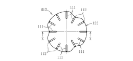
- the third forging die 130 is a so-called closed forging die. That is, as shown in FIGS. 11a and 11c, the third forging die 130 includes a punch 131 and a die 132 that move relatively close to and away from each other. A sealed molding space is defined. Then, when the third forging die 130 is subjected to upsetting on the large-diameter portion of the second intermediate product M12, the large-diameter portion is compressed and deformed in the axial direction and expanded and deformed in the radial direction. As shown in FIG. 3, the third intermediate product M13 having the upsetting portion 122 is obtained.
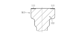
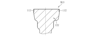
- the third intermediate product M13 is an intermediate forged product 101 having a cup-shaped portion 102 ′′ shown in FIG. 10d by a fourth forging die disposed adjacent to the downstream side of the third forging die 130. To be molded. Further, in the third intermediate product M13, the opening end surface and the outer diameter surface (the end surface and the outer diameter surface of the upsetting portion 122) of the cup-shaped portion 102 ′′ of the intermediate forged product 101 ′′ are respectively intermediate. A plurality of groove-shaped end surface mark portions 111 and outer diameter mark portions 112 are formed at predetermined intervals in the circumferential direction as mark portions that enable visual determination of whether the opening end shape of the cup-shaped portion 102 ′′ of the forged product 101 ′′ is acceptable. ing. The arrangement form of the end face mark part 111 and the outer diameter mark part 112 formed in the upsetting part 122 is the same as the arrangement form of the both mark parts 111 and 112 existing in the cup part 102 shown in FIGS. 9a and 9b.
- the end face mark portion 111 and the outer diameter mark portion 112 are formed on the lower end surface 131a of the punch 131 and the inner wall surface 32a of the die 132 at the same time as the punch 131 and the die 132 are relatively moved to form the upsetting portion 122. Molding is performed by the convex mold parts 131b and 132b provided. Specifically, as shown in FIG. 11 a, the second halfway product M ⁇ b> 12 is disposed on the inner periphery of the die 132, and then the punch 131 is moved relatively closer to the die 132 to thereby move the second halfway. The large diameter portion of the product M12 is compressed and deformed in the axial direction and expanded (see FIG.
- the large diameter portion of the second intermediate product M12 is aligned with the lower end surface 131a of the punch 131 and the inner wall surface 132a of the die 132. And plastically deform.
- the third intermediate product M13 having the upsetting portion 122 is molded, and at the same time, the end surface mark portion 111 and the outer diameter mark portion 112 are respectively molded on the end surface and the outer diameter surface of the upsetting portion 122.
- a plurality of convex mold portions 131b are provided at predetermined intervals in the circumferential direction.
- the mold part 131b extends radially from the outer diameter end of the lower end surface 131a of the punch 131 toward the inner diameter side.
- the height dimension of the mold 131b is appropriately changed according to the size of the outer joint member 101, and is set within a range of 0.1 mm to 5.0 mm, for example.
- a plurality of convex mold parts 132 b provided on the inner wall surface 132 a of the die 132 are provided at the same pitch as the mold parts 131 b of the punch 131.
- the height dimension of the mold part 132b is appropriately changed according to the size of the outer joint member 101 and the like, but, for example, within the range of 0.1 mm to 5.0 mm as with the mold part 131b provided on the punch 131.
- the cup-shaped portion 102 ′′ of the intermediate forged product 101 ′′ has a shape similar to the cup portion 102 of the outer joint member 101 as a finished product. That is, the cup-shaped portion 102 ′′ of the intermediate forged product 101 ′′ has a corollary cross-sectional shape, and three track grooves 105 ′ having roller guide surfaces 106 ′ and 106 ′ are formed at circumferentially equal positions on the inner diameter surface. Roughly molded.
- the cup-shaped portion 102 ′′ of the intermediate forged product 101 ′′ is thicker and shorter in the axial direction than the cup portion 102 of the outer joint member 101 shown in FIG.
- the axial dimension of the track groove 105 ′ provided on the inner diameter surface of the cup-shaped portion 102 ′′ of the intermediate forged product 101 ′′ is the axis of the track groove 105 provided on the inner diameter surface 104 of the cup portion 102 of the outer joint member 101. It is shorter than the directional dimension.
- the intermediate forged product 101 ′′ obtained as described above is transferred to the ironing process.
- the outer peripheral portion corresponds to the shape of the inner diameter surface 104 of the cup portion 102 shown in FIG. 9 as shown in FIG.
- the cup-shaped portion 102 ′′ of the intermediate forged product 101 ′′ is ironed.
- a final forged product 101 ′ having a cup-shaped portion 102 ′ in which the track groove 105 is formed into a finished shape is obtained.
- the final forged product 101 ' is transferred to the finishing process.
- it is difficult to form by the various forging processes described above for example, an annular groove for fitting a boot to be provided on the outer diameter surface of the cup portion 102, or a free end outer diameter of the shaft portion 103).
- Spline etc. is formed by machining such as grinding, and the final forged product 101 'is finished into a finished product shape.
- the outer joint member 101 shown to FIG. 9a and FIG. 9b is completed by giving heat processing, such as hardening, to the final forged product 1 'finished in the shape of the finished product as a whole.
- the intermediate product (the third intermediate product M13 in the present embodiment) that finally becomes the intermediate forged product 101 ′′
- a cup-shaped portion 102 of the intermediate forged product 101 ′′ is formed on the third intermediate product M13 by the molding die portions 131b and 132b provided on the punch 131 and the die 132 constituting the forging die for molding (third forging die 130).
- the end face mark portion 111 and the outer diameter mark portion 112 as the mark portions that enable the visual determination of whether the opening end portion shape is acceptable or not are molded. In this way, after the pre-forging process is completed, the intermediate forged product 101 is formed.
- an intermediate forged product 101 ′′ having a cup-like portion 102 ′′ is obtained by subsequent rearward extrusion.
- the end surface mark portion 111 (the outer diameter portion thereof) and the outer diameter mark portion 112 remains as it is.
- the intermediate forged product 101 ′′ has the cup-shaped portion 102 ′′ having a predetermined shape. It can be easily determined that it is a molded acceptable product.
- the end face mark portion 111 and the outer diameter mark portion 112 having predetermined shapes are molded in a partial region in the circumferential direction of the end face and the outer diameter face of the upsetting portion 122.
- the third intermediate product M13 that has not been obtained is obtained and the third intermediate product M13 is subjected to a backward extrusion process, as shown in FIG. 14c and FIG.
- An intermediate forged product 101 ′′ is obtained in which the end face mark portion 111 and the outer diameter mark portion 112 having a predetermined shape are not present in a partial region in the direction.
- the intermediate forged product 101 ′′ is the intermediate product (second intermediate product). M12) does not accurately follow the third forging die 130, and it can be easily determined that the cup-shaped portion 102 ′′ is a rejected product that has not been formed into a predetermined shape.
- the outer joint member 101 and the manufacturing method thereof according to one embodiment of the second invention have been described above, but the second invention is not limited to the above-described embodiment and does not depart from the gist thereof. It is possible to add various changes.
- the mark portion is formed on the end surface of the upsetting portion 122, which is the portion that becomes the end surface of the cup-shaped portion 102 ′′ of the intermediate forged product 101 ′′ in the third intermediate product M13.
- an upset that is a part that becomes the outer diameter surface of the cup-shaped portion 102 ′′ of the intermediate forged product 101 ′′ in the third intermediate product M13
- the molding may be performed only on the outer diameter surface of the portion 122.
- the second invention is not limited to the case of obtaining the third intermediate product M13 in which the end surface of the upsetting portion 122 forms a flat surface, but also as shown in FIGS. 16a and 16b.
- the present invention can also be preferably applied to the case where the third intermediate product M13 having the upsetting portion 122 provided with the recessed portion 122a in the center is obtained.
- the form of the end face mark portion 111 to be molded on the end face of the third halfway product M13 is not limited to that described above.
- the end face mark portion 111 may be formed in a radial shape so as to cross the end surface of the upsetting portion 122 as shown in FIG. 17a, or one or a plurality of annular shape as shown in FIGS. You may form this.
- the end face mark portions 111 may be formed innumerably in a dotted shape.
- the end face mark portion 111 and / or the outer diameter mark portion 112 is an intermediate forged product that indicates whether or not a forming accuracy failure has occurred in a region where the forming accuracy failure (meat filling failure) is likely to occur in the upsetting portion 122.
- the shape is not particularly limited as long as the determination can be easily made at the stage when 101 ′′ is obtained. Therefore, either one or both of the end face mark portion 111 and the outer diameter mark portion 112 are concavely shaped. You may make it shape
- the third forged hermetic dies when the intermediate forged product 101 ′′ of the outer joint member 101 is obtained through the four steps (using a forging device in which four forging dies are continuously provided), the third forged hermetic dies.
- the end face mark portion 111 and the outer diameter mark portion 112 as the mark portion are molded at the forging step by the forging die 130, the mark portion is formed in another forging step (for example, the second intermediate product M12).
- the second invention can be preferably applied to the case where the intermediate forged product 101 ′′ is obtained by obtaining 3 or less or 5 or more steps.
- the outer joint member 101 shown in FIG. 9, that is, the opening end surface 107 of the cup portion 102 is obtained by the free deformation of the cup-shaped portion 102 ′′ of the intermediate forged product 101 ′′ along the ironing process.
- the outer joint member 101 in which the opening end surface 107 of the cup portion 102 is finished by machining such as turning is used.
- the second invention can be preferably applied also in manufacturing.
- the end face mark portion 111 and / or the outer diameter mark portion 112 basically does not exist in the cup portion 102 of the outer joint member 101.
- the outer joint member 101 for a tripod type constant velocity universal joint (TJ) which is a kind of sliding type constant velocity universal joint
- the second invention is applied when manufacturing the outer joint member 101
- the second invention is applied to the manufacture of other sliding type constant velocity universal joints, such as an outer joint member for a double offset type constant velocity universal joint (DOJ), and this outer joint member. It is also possible.
- the second invention is not limited to the outer joint member for the sliding type constant velocity universal joint described above, but also for the fixed type constant velocity universal joint such as the undercut-free type constant velocity universal joint (UJ). It is also possible to apply when manufacturing a member and this outer joint member.
- the fixed type constant velocity universal joint does not allow axial displacement but allows only angular displacement, and the track groove of the outer joint member incorporated therein is relatively positioned on the cup opening side. It is comprised by the linear part extended in parallel with a joint axis line, and the circular arc-shaped part located in a cup bottom side relatively.
- FIG. 18 shows a constant velocity universal joint A including an outer joint member manufactured by using the manufacturing method according to one embodiment of the third invention.
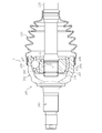
- a constant velocity universal joint A shown in the figure is a six-ball type undercut free constant velocity universal joint (UJ) which is a kind of a fixed type constant velocity universal joint that allows only angular displacement, and includes a cup portion 202.
- the outer joint member 201 integrally having the shaft portion 203, the inner joint member 220 accommodated in the inner periphery of the cup portion 202, and the six balls 230 disposed between the cup portion 202 and the inner joint member 220.
- a cage 231 that is disposed between the inner diameter surface 204 of the cup portion 202 and the outer diameter surface 221 of the inner joint member 220 and holds the balls 230 at predetermined intervals in the circumferential direction.
- the number of balls 230 arranged may be 8, 10, or 12.
- a shaft 232 is connected to the inner circumference of the inner joint member 220 by, for example, spline fitting, and one end and the other end of a bellows-like boot 233 are connected to the shaft 232 and the cup portion 202 of the outer joint member 201. Each is fixed. By fixing the boot 233 in this manner, external leakage of grease (lubricant) enclosed in the joint and further entry of foreign matter into the joint is prevented as much as possible.
- Track grooves 205 and 222 extending in the axial direction are provided at a 60 ° pitch on the inner diameter surface 204 of the cup portion 202 of the outer joint member 201 and the outer diameter surface 221 of the inner joint member 220.
- a ball 230 is disposed in each of the ball tracks formed by the track grooves 205 and 222 forming a pair of the inner joint member 220.
- the track groove 205 of the outer joint member 201 is composed of a linear portion located on the opening end side of the cup portion 202 and an arc-shaped portion located on the side opposite to the opening end of the cup portion 202, and the inner joint member 220.
- the track groove 222 includes an arc-shaped portion positioned on the opening end side of the cup portion 202 and a linear portion positioned on the side opposite to the opening end of the cup portion 202.
- the center of curvature of the arc-shaped portion of the track groove 205 of the outer joint member 201 and the center of curvature of the curved portion of the track groove 222 of the inner joint member 220 are offset equidistantly from each other in the axially opposite direction with respect to the joint center O. It is in.
- the cup portion 202 is configured by arranging six relatively thick portions 206 and six relatively thin portions 207 alternately in the circumferential direction,
- the groove bottom surface of the track groove 205 is formed by the inner diameter surface of the thin portion 207.
- the outer joint member 201 includes a pre-forging step for obtaining an intermediate forged product 201 ′′ shown in FIGS. 19d, 20a and 20b, and an ironing step for obtaining a final forged product 201 ′ shown in FIG. Then, a finishing process for finishing each part of the final forged product 201 ′ into a finished product shape and a heat treatment process for heat-treating the final forged product 201 ′ finished into a finished product shape are completed in order.
- an intermediate forged product 201 having a cup-shaped portion 202 ′′ shown in FIGS. 19d, 20a, and 20b is formed from a rod-shaped material (not shown) through a plurality of forging steps (four steps in the present embodiment).
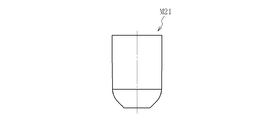
- the first forging product M21 has a relatively large diameter portion on one end side and the other end side (
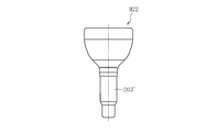
- a second intermediate product M22 having a relatively small-diameter shaft portion 203 ′ (a portion finally finished to the shaft portion 3) is obtained on the side where the outer peripheral edge is rounded.
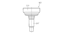
- the large diameter portion of the second intermediate product M22 is upset, and the large diameter portion is compressed and deformed in the axial direction and expanded and deformed in the radial direction, as shown in FIG. 19c.
- a third intermediate product M23 having the upsetting portion 210 and the shaft-like portion 203 ′ is obtained.
- the cup An intermediate forged product 201 ′′ having a shaped portion 202 ′′ is obtained.
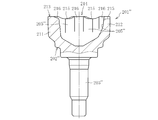
- the cup-shaped portion 202 ′′ of the intermediate forged product 201 ′′ is configured by alternately arranging the thick wall portions 211 and the thin wall portions 212 in the circumferential direction.
- the formed track groove 205 ′′ has a cup-shaped portion 202 ′′ that is thicker and shorter in the axial direction than the cup portion 202 of the outer joint member 201 shown in FIG. Accordingly, the track groove 205 ′′ roughly formed on the inner diameter surface of the cup-shaped portion 202 ′′ is shorter in the axial direction than the track groove 205 provided on the inner diameter surface 204 of the cup portion 202 of the outer joint member 201.
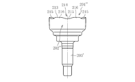
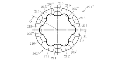
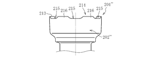
- the opening end surface 213 of the cup-shaped portion 202 ′′ has an uneven portion 214 formed by alternately arranging recesses 215 and protrusions 216 in the circumferential direction.
- the arrangement mode of the concave portion 215 and the convex portion 216 constituting the concave / convex shape portion 214 is opposite to the concave / convex mode of waviness generated on the opening end surface of the cup-shaped portion 202 ′ of the final forged product 201 ′.
- the axial deformation amount (thickness reduction rate) of the workpiece due to ironing is greater in the thin portion than in the thick portion. Therefore, when ironing is performed on the cup-shaped portion of the intermediate forged product in which the opening end surface is formed flat without the uneven portion 214 described above, the opening end surface of the cup-shaped portion of the final forged product is a thin portion. And it becomes convex shape and concave shape in the formation area of a thick part, respectively.
- the concave portion 215 constituting the concavo-convex shape portion 214 is provided in the formation region of the thin portion 212 constituting the cup-shaped portion 202 ′′, while the convex portion 216 is the thick portion 211 constituting the cup-shaped portion 202 ′′.
- the depth dimension of the concave portion 215 (the difference in height between the bottom portion of the concave portion 215 and the top portion of the convex portion 216) is the same as that of the thick portion 211 and the thin portion of the cup-shaped portion 202 ′′ accompanying ironing.
- the recess 215 is a cup-shaped portion.
- a concave curved surface having a partial cylindrical surface is provided on the opening end surface 213 of 202 ′′.
- the concave / convex shape portion 214 is formed at the same time as the cup-shaped portion 202 ′′ (intermediate forged product 201 ′′) having the track grooves 205 ′′ roughly formed on the inner surface is formed.
- the punch 252 is moved relatively close to the die 251, and the third intermediate product M23 is subjected to a backward extrusion process, thereby roughly forming the inner diameter surface.
- the concave-convex shaped portion 214 is molded on the opening end surface 213 of the cup-shaped portion 202 ′′.
- the intermediate forged product 201 ′′ obtained as described above is transferred to the ironing process.
- the cup-shaped portion 202 ′′ of the intermediate forged product 201 ′′ is ironed to extend the cup-shaped portion 202 ′′ in the axial direction.
- a final forged product 201 ′ having a cup-shaped portion 202 ′ in which a finished track groove 205 ′ is formed on the inner diameter surface is obtained. Since the above-described uneven shape portion 214 is provided on the opening end surface 213 of the cup-shaped portion 202 ′′ of the intermediate forged product 201 ′′ subjected to the ironing process, when the ironing process is completed, as shown in FIG.
- a final forged product 201 ′ having a cup-shaped portion 202 ′ with less waviness at the open end face (open end face is substantially flat) is obtained.
- the final forged product 201 ' is transferred to the finishing process.
- it is difficult to form by forging for example, an annular groove for fixing one end portion of the boot 233 to be provided on the outer diameter surface of the cup portion 202 or a free end outer diameter of the shaft portion 203.
- the final forged product 201 ′ is finished into a finished product shape by performing a process for forming a power spline or the like, and a process for turning the opening end surface of the cup-shaped portion 202 ′ as necessary.
- the outer joint member 201 shown in FIG. 19 is completed by performing heat treatment, such as quenching, on the final forged product 201 ′ that has been finished into a finished product shape as a whole.
- the final forging is performed on the opening end surface 213 of the cup-shaped portion 202 ′′ of the intermediate forged product 201 ′′ along with ironing.
- the concavo-convex shape portion 214 is formed by molding the concave and convex portions opposite to the undulation generated on the opening end face of the cup-shaped portion 202 ′ of the product 201 ′. More specifically, in the pre-forging process, the thickness reduction rate (axial deformation amount in the axial direction) associated with the ironing process is taken into consideration so as to coincide with the circumferential region where the roughly formed track groove 205 ′′ exists. Thus, the concave portion 215 of the concave and convex portion 214 was molded.
- the degree of waviness that occurs on the opening end surface of the cup-shaped portion 202 ′ of the final forged product 201 ′ during ironing is reduced without incurring a particular increase in processing costs (the concave and convex portions constituting the waviness).
- the height difference of the portion can be reduced). This makes it possible to improve the productivity by reducing the end face finishing amount (turning amount) of the final forged product 201 ′, and it is also possible to use a rod-shaped material having a volume that is small enough to reduce the end face finishing amount. Thus, the yield can be improved.
- the productivity of the outer joint member 201 which is one constituent member thereof, can be achieved without making design changes that affect the function / performance of the constant velocity universal joint A.
- the yield can be improved, thereby contributing to the cost reduction of the constant velocity universal joint A.
- the punch 252 for forming the inner diameter surface of the cup-shaped portion 202 ′′ of the intermediate forged product 201 ′′ (a plurality of forgings included in the pre-forging step).
- the punch 252) used in the final forging step is provided with a molding die N for molding the concave and convex portion 214, and at the same time as forming the cup-shaped portion 202 ", the concave and convex portion 214 is cup-shaped.
- the mold is formed on the opening end surface 213 of the section 202 ′′, the mold section N for molding the concave and convex portion 214 is formed on a mold 253 provided separately from the punch 252 as shown in FIG. You may make it provide.
- the concavo-convex shape portion 214 does not necessarily have to be molded at the same time as the cup-shaped portion 202 ′′ is formed, and both may be formed in different forging steps.
- a molding die N is provided on the end surface of the punch 262, and the punch 262 and the die 261 are used for installation.
- a third intermediate product M23 is obtained in which the uneven portion 214 is die-molded on the end surface (outer diameter side region) of the upset portion 210.
- the third intermediate product M23 is subjected to backward extrusion using a punch 252 and a die 251 that do not have the mold part N, and a cup-shaped part 202 ′′ (intermediate forged product 201 ′′) is obtained.
- the form of the concave portion 215 constituting the concave-convex shape portion 214 is not limited to the above. That is, in the above-described embodiment, the concave portion 215 is configured by the concave surface of the partial cylindrical surface provided on the opening end surface 213 of the cup-shaped portion 202 ′′. For example, as shown in FIG. 25a, two tapered surfaces are combined.
- the recessed part 215 may be comprised, and as shown to FIG. 25b, you may comprise the recessed part 215 combining a circular arc surface and a flat surface.
- the third invention is applied when the pre-forging process is configured by four forging steps (when the intermediate forging product 201 ′′ is obtained through four forging steps), but the intermediate forging product 201 ′′ is 3 or less.
- the third aspect of the present invention can be preferably applied even when obtaining forging steps of 5 or more.
- the third invention is applied when manufacturing an outer joint member for a six-ball type undercut-free type constant velocity universal joint (UJ) which is a kind of fixed type constant velocity universal joint.
- UJ constant velocity universal joint
- the third invention can be preferably applied to the manufacture of the outer joint member for UJ of the 8-ball type, the 10-ball type, and the 12-ball type.
- the third invention is applied not only when manufacturing the outer joint member for the fixed type constant velocity universal joint as described above but also when manufacturing the outer joint member for the sliding type constant velocity universal joint.
- Sliding constant velocity universal joints allow both angular displacement and axial displacement, and representative examples include tripod type constant velocity universal joints (TJ) and double offset type constant velocity universal joints (DOJ). It is done.
- TJ tripod type constant velocity universal joints
- DOJ double offset type constant velocity universal joints
Landscapes
- Engineering & Computer Science (AREA)
- Mechanical Engineering (AREA)
- General Engineering & Computer Science (AREA)
- Forging (AREA)
Description
本発明は、例えば、自動車、航空機、船舶および各種産業機械などの動力伝達系において使用され、駆動側と従動側の二軸間で回転動力を等速で伝達する等速自在継手用の外側継手部材の製造方法および外側継手部材に関する。
周知のように、等速自在継手は、角度変位のみを許容する固定式等速自在継手と、角度変位および軸方向変位を許容する摺動式等速自在継手とに大別される。等速自在継手は、固定式であるか摺動式であるかに関わらず、一端が開口したカップ部を有し、カップ部の内径面に軸方向に延びる複数のトラック溝が設けられた外側継手部材と、カップ部の内周に収容される内側継手部材やトルク伝達部材などの継手内部部品とを主要な構成部材として備える。これら継手構成部材のうち、外側継手部材は、切削や旋削に代表される機械加工、鍛造に代表される塑性加工などの各種加工法を駆使して製造されるが、生産効率や歩留の向上を図るべく、近年では可能な限りにおいて塑性加工を採用する場合が多い。
一例として、下記の特許文献1には、摺動式等速自在継手の一種であるトリポード型等速自在継手の外側継手部材、特に、一端が開口し、内径面に軸方向に延びる複数のトラック溝が設けられた有底筒状のカップ部と、このカップ部の他端から軸方向外方に延びる軸部とを一体に備える外側継手部材を、塑性加工で製造する方法が記載されている。具体的には、据え込み、前方押し出しおよび後方押し出しなどにより、棒状素材を、内径面にトラック溝が粗成形されたカップ状部を有する中間鍛造品に成形する前鍛造工程と、中間鍛造品のカップ状部にしごき加工を施すことにより、内径面に仕上がり形状(最終形状)のトラック溝が成形されたカップ状部を有する最終鍛造品を得るしごき工程とを含む外側継手部材の製造方法である。
なお、上記のような製造方法(手順)は、摺動式等速自在継手用の外側継手部材のみならず、アンダーカットフリー型に代表される固定式等速自在継手用の外側継手部材を製造する際にも好ましく適用し得る。
ところで、最終鍛造品の形状(各部寸法)は、棒状素材相互間の重量や体積にばらつきがあることなどを理由として個体間でばらつき易く、その中でもカップ状部の開口端部は、特にばらつきが大きく現れ易い部位である。そのため、最終鍛造品を、旋削や研削等の仕上げ加工を施すための仕上げ工程、あるいは焼入れを施すための熱処理工程などの後工程に払い出す前には、最終鍛造品のカップ状部の開口端部が所定形状に成形されているか否か(カップ状部のカップ深さが公差範囲内に収まっているか否か)を検査し、合格品のみを後工程に払い出すようにしている。
従前、カップ深さが公差範囲内に収まっているか否かの検査(カップ深さの合否判定)は、例えば、図26に示すような専用の測定器具300(詳細には、カップ状部内底面との当接部を有する軸方向部301a、およびカップ状部内径面との当接部を有する径方向部301bからなる断面略T字形状の治具301と、スケール302とを組み合わせてなるもの)を用いて測定し、その測定結果を、製品毎の寸法規格と照らし合わせることにより実行していた。
しかしながら、この場合、測定器具300の設置→スケール302の読み取り→測定器具300の取り外しという手順を踏む必要がある。しかも正確な合否判定を行うためには、治具301やスケール302を精度良く位置決め配置すると共に、スケール302の読み取りに格別の配慮を払う必要がある。そのため、カップ深さの合否判定に多大な手間を要し、外側継手部材の生産性(生産効率)を有効に高め得ないという問題がある。また、スケール302の読み取り値にばらつき(個人差)が生じ易いことから、合否判定の精度を高めるうえでも改善すべき課題がある。
また、中間鍛造品、あるいは最終鍛造品におけるカップ状部の開口端部形状は、棒状素材の重量や体積のみならず、前鍛造工程の途中段階で得られる途中製品(最終的に中間鍛造品となる製品)の成形精度によっても左右される。そのため、途中製品あるいは中間鍛造品が所定形状に成形されたか否か、さらに言えば、ワークが前鍛造工程で使用する鍛造金型に倣って適切に塑性変形したか否かを簡便に判定・確認することができれば、煩雑な検査処理を簡便化あるいは省略することができる他、しごき加工後に不良品となる可能性が高い中間鍛造品にわざわざしごき加工を施す必要がなくなるので、外側継手部材の生産性を向上し得る。
しかしながら、中間鍛造品を得るための前鍛造工程は、複数の鍛造金型が送り方向に沿って連設された鍛造装置(トランスファープレス)を使用して連続的に実行されるのが一般的である。そのため、途中製品が所定形状に成形されているか否か、すなわち、ワークが鍛造金型に倣って適切に塑性変形したか否かを判定・確認しようとすると、鍛造装置を全停止して抜き取り検査を実行する必要がある。しかし、これでは、外側継手部材の生産性が著しく低下する。また、鍛造装置から抜き取った途中製品を鍛造装置に再投入すると加工不良が生じ易くなることから、抜き取った途中製品が合格品であったとしても、この途中製品を鍛造装置に再投入することはできない。このため、鍛造装置から抜き取った途中製品が合格品であった場合にも、その途中製品は廃棄せざるを得ず、結果として製品歩留の低下を招来する。
また、上記のような手順を踏んで外側継手部材を得るようにした場合、図27aに示すように、最終鍛造品400のカップ状部401の開口端面402は、トラック溝403の形成領域およびトラック溝403間領域がそれぞれ凸状および凹状となるようにして大きく波打つ(うねる)ことが多く、その結果として、必要とされるカップ深さを全周に亘って確保することができない場合がある。このような問題は、例えば、比較的大きな棒状素材を使用して中間鍛造品、ひいては最終鍛造品400を得た後、うねりが生じたカップ状部401の開口端面402を所定量旋削することによって解消することができる。しかしながら、このようにすると、大幅な端面仕上げが必須となるために生産性が低下する他、必要以上に大きな棒状素材を使用する必要があるために歩留の低下を招来する。
最終鍛造品400のカップ状部401の開口端面402に生じるうねりは、しごき加工に伴う中間鍛造品のカップ状部の肉厚減少率が中間鍛造品のカップ状部の周方向各部間で異なること、すなわち図27bに示すように、しごき加工に供される中間鍛造品400’のカップ状部401’の肉厚が周方向の各部で異なること、を主たる要因として生じるものと考えられる。そのため、外側継手部材のカップ部の周方向各部間での肉厚差が小さくなるような製品設計を行えば、上記の問題を緩和、もしくは解消し得るとも考えられる。しかしながら、外側継手部材のカップ部の周方向各部における肉厚は、等速自在継手の機能・性能等を考慮して決定付けられるので、安易に変更することはできない。
このような実情に鑑み、本発明の目的は、等速自在継手の一構成部材である外側継手部材の生産性や製品歩留の向上を図り、もって等速自在継手の低コスト化に寄与することにある。
上記の目的を達成するために創案された本願の第1発明に係る外側継手部材の製造方法は、一端が開口したカップ部を有し、カップ部の内径面に軸方向に延びる複数のトラック溝が設けられた等速自在継手用外側継手部材の製造方法であって、複数の鍛造加工を段階的に実行することにより、棒状素材から、内径面にトラック溝が粗成形されたカップ状部を有する中間鍛造品を得る前鍛造工程と、中間鍛造品のカップ状部にしごき加工を施すことにより、内径面に仕上がり形状のトラック溝が成形されたカップ状部を有する最終鍛造品を得るしごき工程とを含み、しごき工程で中間鍛造品のカップ状部にしごき加工を施す際に、カップ深さの合否を目視判定可能とするための判定基準部を型成形することを特徴とする。
また、上記の目的を達成するために創案された第1発明に係る外側継手部材は、一端が開口したカップ部を有し、該カップ部の内径面に軸方向に延びる複数のトラック溝が設けられた等速自在継手用外側継手部材であって、カップ部が鍛造により成形され、かつトラック溝の一部又は全部が、鍛造後のしごき加工で仕上がり形状に成形されたものにおいて、カップ部のカップ深さの合否を目視判定可能とするための判定基準部を有し、該判定基準部が、しごき加工で使用する金型による型成形により設けられていることを特徴とする。
上記本発明の構成によれば、しごき加工完了後に、カップ深さの合否、すなわち、カップ深さが寸法公差内に収まっているか否かを、判定基準部の存否や形成態様を目視確認するだけで判定することが可能となる。より具体的には、カップ部(カップ状部)のしごき加工による成形面に所定態様の判定基準部が型成形されていれば、カップ深さが公差範囲内に収まっていると判定し得る一方で、カップ部(カップ状部)のしごき加工による成形面に判定基準部が所定態様で型成形されていなければ、カップ深さが公差範囲内に収まっていないと判定することが可能となる。そのため、図26に示したような専用の測定器具300を用いてカップ深さの合否判定を実行する必要がなくなり、カップ深さの合否判定を簡便に実行することが、また判定精度を向上することができる。これにより、外側継手部材の生産性向上を図ることができる。
第1発明に係る外側継手部材の製造方法においては、最終鍛造品のカップ状部の軸方向に離間した二箇所に判定基準部を型成形することができる。すなわち、しごき加工の実行時には、最終鍛造品のカップ状部の軸方向に離間した二箇所に判定基準部を型成形可能な金型を使用することができる。このような方法を採用してしごき加工を施した場合、カップ部(カップ状部)の他端側(反開口端部側)に型成形される判定基準部をカップ深さの公差下限を示す部位として活用することができ、カップ部(カップ状部)の一端側(開口端部側)に型成形される判定基準部をカップ深さの公差上限を示す部位として活用することができるので、しごき加工の完了後に、カップ深さが公差範囲内に収まっているか否かを一層正確に判定することが可能となる。さらに詳しく言えば、カップ部(カップ状部)の軸方向一箇所に判定基準部が所定態様で型成形されていれば、カップ深さが公差範囲内に収まっていると判定することができる。そして、カップ部(カップ状部)の軸方向に離間した二箇所に判定基準部が所定態様で型成形されていれば、カップ深さが公差範囲を超えた不合格品であると判定することができ、また、成形面に所定態様の判定基準部が型成形されていなければ、カップ深さが公差範囲を下回った不合格品であると判定することができる。
また、第1発明に係る外側継手部材の製造方法は、しごき加工の後、最終鍛造品のカップ状部の一端部(開口端部)を所定寸法除去する端部除去工程をさらに含むものとすることができ、この端部除去工程では、判定基準部の全体が除去される軸方向位置に至って最終鍛造品のカップ状部の一端部を除去することができる。すなわち、しごき加工で型成形した判定基準部は、最終鍛造品のカップ状部の一端部を軸方向に所定寸法除去して仕上げる際の目印として活用することもできる。
判定基準部は、外側継手部材の機能を阻害しない範囲において任意の形態を採ることができる。例えば、カップ部の周方向で連続的に設ける(カップ部の全周に亘って設ける)ことができる他、カップ部の周方向で間欠的に設けることもできる。また、判定基準部は、例えば、高低差が0.01mm以上1.0mm以下の段差部、高さ寸法が0.01mm以上1.0mm以下の突状部、あるいは深さ寸法が0.01mm以上1.0mm以下の凹状部で構成することができる。判定基準部の高低差、高さ寸法、あるいは深さ寸法(以下「高低差等」という)の下限値を0.01mmに設定したのは、カップ深さの合否判定を正確かつ迅速に実行するためであり、高低差等が0.01mmを下回るような微小なものであると、カップ深さの合否判定を正確かつ迅速に実行できない可能性が高まる。また判定基準部の高低差等の上限値を1.0mmに設定したのは、高低差等が1.0mmを超えると、カップ状部の離型性、ひいてはカップ部の成形精度に悪影響が及ぶ可能性があるからである。
以上で述べた第1発明は、トラック溝が、継手軸線と平行に延びる直線状部分のみで構成された外側継手部材、すなわち摺動式等速自在継手用の外側継手部材に適用することができる。適用可能な摺動式等速自在継手としては、トリポード型等速自在継手(TJ)や、ダブルオフセット型等速自在継手(DOJ)を挙げることができる。また、第1発明は、トラック溝が、相対的にカップ部の一端側(開口端部側)に位置して継手軸線と平行に延びる直線状部分と、相対的にカップ部の他端側(反開口端部側)に位置する円弧状部分とで構成された外側継手部材、すなわち固定式等速自在継手の一種であるアンダーカットフリー型等速自在継手(UJ)用の外側継手部材に適用することもできる。なお、例示した何れのタイプの等速自在継手用外側継手部材においても、トラック溝の直線状部分は、中間鍛造品のカップ状部にしごき加工を施すことで仕上がり形状に成形することができる。
第1発明に係る外側継手部材と、そのカップ部内周に収容した継手内部部品とで等速自在継手を構成することができる。
第1発明の構成において、しごき加工は冷間、温間あるいは熱間の何れの雰囲気下で実行しても構わないが、冷間で実行するようにすれば、温間あるいは熱間で実行する場合に比べてカップ部の成形精度(しごき加工の精度)を向上することができる。
また、上記の目的を達成するために創案された第2発明に係る外側継手部材の製造方法は、一端が開口したカップ部を有し、カップ部の内径面に軸方向に延びる複数のトラック溝が設けられた等速自在継手用外側継手部材の製造方法であって、複数の鍛造加工を段階的に実行することにより、棒状素材から、内径面にトラック溝が粗成形されたカップ状部を有する中間鍛造品を得る前鍛造工程と、中間鍛造品のカップ状部にしごき加工を施すことにより、内径面に仕上がり形状のトラック溝が成形されたカップ状部を有する最終鍛造品を得るしごき工程とを含み、前鍛造工程で最終的に中間鍛造品となる途中製品を成形する際に、中間鍛造品のカップ状部の開口端部形状の合否を目視判定可能とする目印部を型成形することを特徴とする。
このようにすれば、前鍛造工程の終了後、中間鍛造品のカップ状部に所定態様の目印部が型成形されているか否かを確認することにより、中間鍛造品のカップ状部の開口端部が所定形状に成形されたか否か(ワークが複数の鍛造金型に倣って適切に塑性変形したか否か)を容易に判定することができる。特に、最終的に中間鍛造品となる途中製品に上記の目印部を型成形するようにしたことから、成形精度不良が生じ易い鍛造加工段階において、鍛造金型に設けた成形型部で目印部を型成形するようにすれば、その鍛造加工段階における成形条件の見直し等を簡便に実行することが可能となる。そのため、前鍛造工程において、鍛造装置を全停止して抜き取り検査を実行する必要がなくなる他、しごき加工後に不良品となる可能性が高い中間鍛造品にしごき加工を施す手間を省略することが可能となる。これらのことから、外側継手部材の生産性や製品歩留の低下問題が生じるのを可及的に回避することができる。
上記の構成は、前鍛造工程に密閉鍛造金型による鍛造加工段階が含まれている場合に好ましく適用することができる。なお、ここでいう密閉鍛造金型とは、ワーク全体を金型内に密閉した状態で鍛造加工を施すように構成された鍛造金型をいう。本願発明者らの検証によれば、密閉鍛造金型を使用しての鍛造加工段階では、肉の充足不良に起因した成形精度不良が特に生じ易い。そのため、前鍛造工程のうち密閉鍛造金型による途中製品の鍛造加工段階で目印部を型成形するようにすれば、この鍛造加工段階での材料の充足度合いを適切に把握し、外側継手部材の生産性や製品歩留の向上を図るうえで有利となる。
上記の目印部は、中間鍛造品のカップ状部のうち、目視が容易な部位に型成形するのが望ましい。具体的には、途中製品のうち、中間鍛造品のカップ状部の開口端面(開口側の端面)となる部位に、目印部としての端面目印部を型成形することができる。端面目印部の形態は特に問わず、例えば、放射状に複数成形しても良いし、散点状に無数成形しても良いし、あるいは環状に(一又は複数)成形しても良い。また、途中製品のうち、中間鍛造品のカップ状部の開口端面となる部位に替えて、あるいは開口端面となる部位に加え、中間鍛造品のカップ状部の外径面となる部位に目印部としての外径目印部を型成形しても良い。また、これら目印部(端面目印部および外径目印部)は、凹状に形成しても良いし、凸状に形成しても良い。どのような形態の目印部を型成形するにせよ、目印部が最終製品においても残存する場合を考慮して、目印部は作動性等に悪影響が及ばないような形態とするのが望ましい。
また、上記の目的を達成するために創案された第2発明に係る外側継手部材は、一端が開口したカップ部を有し、カップ部の内径面に軸方向に延びる複数のトラック溝が設けられた外側継手部材であって、カップ部が鍛造により成形され、かつトラック溝の一部又は全部が、鍛造後のしごき加工で仕上がり形状に成形されたものにおいて、カップ部の開口端部に、その開口端部形状の合否を目視判定可能な目印部が鍛造金型による型成形により設けられていることを特徴とする。
このような構成を有する外側継手部材であれば、上記した第2発明に係る外側継手部材の製造方法を採用した場合と同様の作用効果を享受することができる。この場合、目印部は、カップ部の開口側端面、カップ部の外径面、あるいはこれら両方に設けることができる。
第2発明についても、カップ部の他端から軸方向外方に延びる軸部を一体に有する外側継手部材に好ましく適用することができる。
また、第2発明は、トラック溝が直線状部分のみで構成された外側継手部材、すなわち摺動式等速自在継手用の外側継手部材に適用することができる。適用可能な摺動式等速自在継手としては、トリポード型等速自在継手(TJ)や、ダブルオフセット型等速自在継手(DOJ)を挙げることができる。この場合、トラック溝の全部(全域)をしごき加工で仕上げられたものとすることができる。また、第2発明は、トラック溝が、相対的にカップ部の一端側(開口端部側)に位置する直線状部分と、相対的にカップ部の他端側(反開口端部側)に位置する円弧状部分とで構成された外側継手部材、すなわち固定式等速自在継手の一種であるアンダーカットフリー型等速自在継手(UJ)用の外側継手部材に適用することもできる。この場合、トラック溝のうちで少なくとも直線状部分はしごき加工で仕上げられたものとすることができる。
また、以上に述べた第2発明に係る外側継手部材と、そのカップ部内周に収容した継手内部部品とで等速自在継手を構成することができる。
また、上記の目的を達成するために創案された第3発明に係る製造方法は、一端が開口したカップ部を有し、カップ部の内径面に軸方向に延びる複数のトラック溝が設けられた等速自在継手用外側継手部材の製造方法であって、棒状素材から、内径面にトラック溝が粗成形されたカップ状部を有する中間鍛造品を得る前鍛造工程と、中間鍛造品にしごき加工を施すことにより、内径面に仕上がり形状のトラック溝が成形されたカップ状部を有する最終鍛造品を得るしごき工程とを含み、前鍛造工程では、中間鍛造品のカップ状部の開口端面に、しごき加工に伴って最終鍛造品のカップ状部の開口端面に生じるうねりとは凹部と凸部の配置態様が反対の凹凸形状部を型成形することを特徴とする。
このようにすれば、しごき加工に伴って最終鍛造品の開口端面に生じるうねりの程度を、特段の加工コスト増を招くことなく軽減する(うねりを構成する凹部と凸部の高低差を小さくする)ことができる。これにより、最終鍛造品の端面仕上げ量(旋削量)を少なくして生産性を向上することができる他、端面仕上げ量を減少し得る分だけ体積の小さい棒状素材を使用することが可能となり、歩留向上を図ることができる。特に、うねりの程度が大幅に軽減されれば、最終鍛造品に対する端面仕上げを省略することが可能となる。また、第3発明の構成を採用すれば、製品設計上、カップ部の周方向各部の肉厚を変更する必要はなく、従って、等速自在継手の機能・性能等に影響が及ぶことはない。以上のことから、第3発明によれば、等速自在継手の機能・性能に影響を及ぼすような設計変更を行うことなく、その一構成部材である外側継手部材の生産性および歩留の向上を図り、もって等速自在継手の低コスト化に寄与することができる。
外側継手部材のカップ部は、薄肉部と厚肉部とを周方向で交互に配して構成されるのが一般的であり、またトラック溝(の溝底面)は、薄肉部の内径面で構成されるのが一般的である。さらに、しごき加工に伴う肉厚減少率(軸方向の伸長変形量)は、相対的に厚肉の部分よりも相対的に薄肉の部分で大きくなる。そのため、前鍛造工程では、トラック溝が粗成形された周方向領域と、凹凸形状部の凹部が型成形された周方向領域とが一致したカップ状部を有する中間鍛造品を得るようにするのが望ましい。これにより、最終鍛造品の開口端面のうねり量を効果的に低減することができる。
前鍛造工程は複数の鍛造加工段階を含んで構成されるのが一般的である。そして、その最終段階(例えば後方押し出し)で内径面にトラック溝が粗成形されたカップ状部を成形するのと同時に、上記の凹凸形状部を型成形することができる。このとき、凹凸形状部は、トラック溝の粗成形用パンチに設けた成形型部で型成形しても良いし、トラック溝の粗成形用パンチとは別の成形金型に設けた成形型部で型成形するようにしても良い。
また、凹凸形状部の型成形と、内径面に粗成形されたトラック溝を有するカップ状部の成形とは別の鍛造ステップで実行するようにしても良い。具体的には、凹凸形状部を型成形した後の鍛造ステップで、内径面にトラック溝が粗成形されたカップ状部を有する中間鍛造品を得ることができる。
第3発明は、カップ部の他端から軸方向外方に延びる軸部を一体に有する外側継手部材を製造する際にも好ましく適用することができる。
第3発明は、各トラック溝が直線状部分のみで構成された外側継手部材、例えばトリポード型等速自在継手(TJ)やダブルオフセット型等速自在継手(DOJ)などに代表される摺動式等速自在継手用の外側継手部材を製造する際に適用することができる。また、第3発明は、各トラック溝が、相対的にカップ部の一端側(開口端部側)に位置する直線状部分と、相対的にカップ部の他端側(反開口端部側)に位置する円弧状部分とで構成された外側継手部材、例えば固定式等速自在継手の一種であるアンダーカットフリー型等速自在継手(UJ)用の外側継手部材を製造する際に適用することもできる。
以上に示すように、本発明によれば、等速自在継手の一構成部材である外側継手部材の生産性や製品歩留の向上を図ることができる。これにより、等速自在継手の低コスト化に寄与することができる。
以下、本願の第1発明の実施の形態を図面に基づいて説明する。なお、以下では、便宜上、まず第1発明に係る外側継手部材の一実施形態を図1に基づいて説明し、続いて、第1発明に係る外側継手部材の製造方法の一実施形態を図2~図5に基づいて説明する。
図1aに、第1発明の一実施形態に係る等速自在継手用外側継手部材1(以下、単に「外側継手部材1」という)の概略正面図を示し、図1bに同外側継手部材1の概略断面図を示す。この外側継手部材1は、角度変位および軸方向変位の双方を許容する摺動式等速自在継手の一種であるトリポード型等速自在継手(TJ)用の外側継手部材であって、一端が開口した有底筒状のカップ部2と、カップ部2の他端から軸方向外方に延びた軸部3とを一体に備える。トリポード型等速自在継手は、この外側継手部材1のカップ部2の内周に、内側継手部材としてのトリポード部材やトルク伝達部材としてのローラなどを組み込むことで構成される。
カップ部2の内径面4の周方向等分位置には、軸方向に延びる3本のトラック溝5が形成されている。各トラック溝5は、円周方向で対向する一対のローラ案内面6,6を有し、ローラ案内面6,6も含めて継手軸線と平行に延びた直線状に形成されている。図1aからも明らかなように、本実施形態のカップ部2の軸直交断面は、大径部と小径部とを周方向で交互に三つずつ配設して構成される花冠状とされ、各大径部の内周にトラック溝5が形成されている。なお、実際の製品においては、カップ部2の開口部内周縁のトラック溝5,5間領域に、継手の角度変位を許容するため(図示しないトリポード部材から延びる軸との干渉を回避するため)の入口チャンファが設けられるが、図1ではその図示を省略している。また、実際の製品においては、カップ部2の外径面に、継手内部を密封するブーツの一端部を嵌着するための環状溝が設けられるが、図1ではその図示を省略している。
詳細は後述するが、この外側継手部材1は、押し出し加工、据え込み加工およびしごき加工等の塑性加工工程を順次経ることで略完成品形状の最終鍛造品1’(図4中の二点鎖線を参照)を得た後、この最終鍛造品1’に適当な仕上げ加工、さらには熱処理を施すことにより完成する。トラック溝5やローラ案内面6を含め、カップ部2の内径面4全域は、中間鍛造品1”のカップ状部2’(図3を参照)にしごき加工を施すことで最終形状に仕上げられている。なお、本実施形態の外側継手部材1のカップ部2の開口側端面7は、中間鍛造品1”のカップ状部2’にしごき加工を施すのに伴ってカップ状部2’の開口側端部が自由変形することによって得られた面であり、旋削等の仕上げ加工により仕上げられた面ではない。
カップ部2の内径面4の軸方向所定位置には、中間鍛造品1”のカップ状部2”にしごき加工を施すのと同時に型成形された判定基準部(第1判定基準部12)としての段差部14が設けられ、段差部14は、カップ部2の周方向で連続的に(カップ部2の全周に亘って)設けられている。ここで、判定基準部とは、しごき加工完了後に、カップ深さDが公差範囲内に収まっているか否かを判定する際の基準として活用される部位である。上記のように括弧書きで“第1判定基準部12”としたのは、この判定基準部が、カップ深さDが公差下限(必要カップ深さの公差下限)を超えているか否かを判定する際の基準として活用される部位であるからである。つまり、詳細は後述するが、カップ部2の内径面4には、図5bに示すように、カップ深さDが公差上限(必要カップ深さの公差上限)を超えているか否かを判定する際の基準となる第2判定基準部13がさらに型成形される場合がある。
本実施形態においては、図1b中に符号x1で示す軸直交平面が必要カップ深さの公差下限であり、軸直交平面x1を表示するために第1判定基準部12としての段差部14の底側端部14aを軸直交平面x1に合わせて型成形している。そして、この外側継手部材1は、第1判定基準部12としての段差部14の全体がしごき加工による成形面であるカップ部2の内径面4に存在し、第2判定基準部13としての段差部14(図5b参照)がカップ部2の内径面4に存在しないことから、カップ深さDが公差範囲内に収まった合格品であることが目視確認で判定可能である。
なお、第1判定基準部12(さらには図5bに示す第2判定基準部13)としての段差部14の高低差y1は0.01mm以上1.0mm以下に設定される。高低差y1の下限値を0.01mmに設定したのは、カップ深さDの合否判定を正確かつ迅速に実行するためであり、高低差y1が0.01mmを下回るような微小なものであると、カップ深さDの合否判定を正確かつ迅速に実行できない可能性が高まる。また高低差y1の上限値を1.0mmに設定したのは、高低差y1が1.0mmを超えると、しごき加工に使用する成形金型からのカップ状部2’の離型性に悪影響が及ぶ他、ローラの転動性等に悪影響が及ぶ可能性があるからである。
以下、本発明に係る外側継手部材の製造方法についての実施形態、すなわち以上で述べた外側継手部材1を製造するための方法について、図2~図5を参照しながら詳述する。外側継手部材1は、カップ状部2”を有する中間鍛造品1”(図3参照)を得るための前鍛造工程(図2a~図2d参照)、中間鍛造品1”のカップ状部2”にしごき加工を施すしごき工程(図4)、しごき工程を経て得られた最終鍛造品1’の各部を最終形状に仕上げる仕上げ加工工程、および最終形状に仕上げられた最終鍛造品1’に熱処理を施す熱処理工程などを経て完成する。
前鍛造工程は、複数の鍛造加工段階で構成される。具体的には、まず、第1の鍛造加工段階で図2aに示す中実の棒状素材(ビレット)Mに前方押し出し加工を施し、図2bに示すように、棒状素材Mの一端外周縁部が丸められると共に、棒状素材Mの一端中央部が膨出した第1の途中製品M1を得る。次いで、第2の鍛造加工段階で第1の途中製品M1にさらに前方押し出し加工を施すことにより、図2cに示すように、外周縁部が丸められた側に軸状部3’が成形された第2の途中製品M2を得る。次いで、第3の鍛造加工段階で第2の途中製品M2に据え込み加工を施すことにより、図2dに示すように、軸状部3’と一体に据え込み部2Aが成形された第3の途中製品M3を得る。
次に、第4の鍛造加工段階で第3の途中製品M3の据え込み部2Aに対して後方押し出し加工を施すことにより、図3に示すように、内径面に粗成形されたトラック溝5’を有するカップ状部2”を備えた中間鍛造品1”を得る。中間鍛造品1”のカップ状部2”は、完成品としての外側継手部材1のカップ部2に近似した断面形状を具備する。すなわち、中間鍛造品1”のカップ状部2”は断面花冠状を呈し、その内径面にローラ案内面6’,6’を有するトラック溝5’が形成されている。但し、中間鍛造品1”のカップ状部2”は、完成品としての外側継手部材1のカップ部2よりも厚肉でかつ軸方向に短寸である。そのため、トラック溝5’の軸方向寸法は、トラック溝5の軸方向寸法よりも短寸である。
次いで、中間鍛造品1”をしごき加工工程に移送する。しごき加工工程では、図4に示すしごきパンチ20と、しごきダイス30とを備えた成形金型を用いて中間鍛造品1”のカップ状部2”にしごき加工を施し、カップ状部2”の内径面を仕上がり形状に成形する。
しごきパンチ20の先端部外周には、中間鍛造品1”のカップ状部2”の内径面を仕上がり形状に成形するための成形型部21が設けられている。成形型部21の軸方向に離間した二箇所には、第1および第2の判定基準成形部22,23が設けられている。第1の判定基準成形部22とは、カップ部2(最終鍛造品1’のカップ状部2’)のカップ深さDが必要カップ深さの公差下限を超えているか否かを検査・判定する際の基準となる第1判定基準部12(図1b等を参照)を型成形可能な部位である。一方、第2の判定基準成形部23とは、カップ部2のカップ深さDが必要カップ深さの公差上限を超えているか否かを検査・判定する際の基準となる第2判定基準部13(図5b参照)を型成形可能な部位である。従って、パンチ20の先端面20aと第1の判定基準成形部22の端部22aとの軸方向離間距離L1は、カップ深さD(必要カップ深さ)の公差下限値と等しく、パンチ20の先端面20aと第2の判定基準成形部23の端部23aとの軸方向離間距離L2は、カップ深さD(必要カップ深さ)の公差上限値と等しい。
以上の構成からなる成形金型に中間鍛造品1”を位置決め配置し、中間鍛造品1”のカップ状部2”の内周にしごきパンチ20を挿入する。この状態で、しごきパンチ20に対してしごきダイス30を軸方向に相対移動させると、この相対移動に伴って中間鍛造品1”のカップ状部2”にしごき加工が施される。しごき加工が進行するのに伴って、カップ状部2”が軸方向に伸長変形し、これと同時に、カップ状部2”の内径面がしごきパンチ20の成形型部21に倣って塑性変形する。しごきパンチ20に対するしごきダイス30の軸方向の相対移動が完了すると、内径面に仕上がり形状のトラック溝が成形されたカップ状部2’を有する最終鍛造品1’(図4中に二点鎖線で示す)が得られる。
この最終鍛造品1’を成形金型から取り出した後、最終鍛造品1’のカップ深さDが寸法公差内に収まっているか否かを検査する。本実施形態では、しごき工程で第1および第2の判定基準部12,13を軸方向に離間した二箇所に型成形したことから、最終鍛造品1’のカップ状部2’、さらに言えば完成品としての外側継手部材1のカップ部2のカップ深さDが公差範囲内に収まっているか否かを目視確認することが可能となる。すなわち、図5aに示すように、最終鍛造品1’のカップ状部2’の内径面に、第1および第2の判定基準部12,13が一切存在していなければ、カップ深さDが公差下限を下回った不良品であると判定することができる。一方、図5bに示すように、最終鍛造品1’のカップ状部2’の内径面に第1および第2の判定基準部12,13が存在していれば、カップ深さDが公差上限を上回った不良品であると判定することができる。
このように、本願の第1発明では、しごき工程において、中間鍛造品1”のカップ状部2”にしごき加工を施す際に、カップ深さDが公差範囲内に収まっているか否かを判定するための判定基準部を型成形した。このようにすれば、カップ深さDが公差範囲内に収まっているか否かの判定を、カップ状部2’(カップ部2)の内径面に型成形された判定基準部(第1および第2の判定基準部12,13)の存否や形成態様を目視確認するだけで判定することが可能となる。そのため、図26に示したような専用の測定器具300を用いてカップ深さDの測定・検査処理を実行する必要がなくなり、測定・検査処理の作業性を向上することが、また合否判定精度を向上することができる。これにより、外側継手部材1の生産性向上および歩留向上が図られる。
上記のようにして、カップ深さDが寸法公差内に収まっていると判定された合格品は後工程に払い出される。そして、例えば、最終鍛造品1’のカップ状部2’の外径面にブーツ固定用の環状溝を、また、最終鍛造品1’の軸状部3’にスプライン等を形成した後、これに熱処理を施すことにより、カップ部2および軸部3を一体に有する外側継手部材1(図1a,図1b参照)が完成する。
以上、第1発明の一実施形態に係る外側継手部材1およびその製造方法について説明を行ったが、第1発明は、上記の実施形態に限定適用されるものではなく、その要旨を逸脱しない範囲で種々の変更を加えることが可能である。
例えば、判定基準部(第1および第2の判定基準部12,13)は、図6aに示すように、高さ寸法y2が0.01mm以上1.0mm以下の突状部15で構成しても良いし、図6bに示すように、深さ寸法y3が0.01mm以上1.0mm以下の凹状部16で構成しても良い。なお、図6a,図6bは、外側継手部材1のカップ部2の内径面4の全周に亘って、第1の判定基準部12としての突状部15および凹状部16を形成した場合を例示している。
また、図7に示すように、判定基準部(図示例では第1の判定基準部12)は、カップ部2の周方向で間欠的に設けるようにしても良い。特に図7に示すように、トラック溝5の形成領域を除く周方向領域に判定基準部を設けるようにすれば、判定基準部を設けることによるトルク伝達部材(ローラ)の転動性低下を考慮せずとも足りる。なお、図7は、判定基準部(第1の判定基準部12)として凹状部16を採用した場合を示しているが、判定基準部として段差部14あるいは突状部15を採用する場合にも、かかる構成を採用することができる。
また、図1に示した外側継手部材1は、中間鍛造品1”のカップ状部2”の開口側端部がしごき加工に伴って自由変形することにより得られた面でカップ部2の開口側端面7を構成したものであるが、カップ部2の開口側端面7は、図8に示すように、旋削加工で仕上げられた面とすることも可能である。すなわち、図4に示すしごき工程の後、最終鍛造品1’のカップ状部2’の開口端部を所定寸法除去する端部除去工程としての旋削工程をさらに設け、この旋削工程で、カップ状部2’の開口端部を第1の判定基準部12(段差部14)の全体が除去される軸方向位置に至って旋削するようにしても良い。この場合、カップ状部2’の内径面に型成形した第1の判定基準部12としての段差部14は、旋削加工の終了位置(カップ部2の開口側端面7の形成位置)を示す目印としても活用することができる。
また、以上では、カップ部2の内径面4(最終鍛造品1’のカップ状部2’の内径面)に判定基準部を型成形するようにしたが、判定基準部は、カップ部2の内径面4に替えて、あるいはカップ部2の内径面4に加えてカップ部2の外径面に型成形するようにしても構わない(図示省略)。
また、以上では、摺動式等速自在継手の一種であるトリポード型等速自在継手(TJ)用の外側継手部材1、およびこの外側継手部材1を製造するに際して第1発明を適用した場合について説明を行ったが、第1発明は、その他の摺動式等速自在継手、例えばダブルオフセット型等速自在継手(DOJ)用の外側継手部材、およびこの外側継手部材を製造する際に適用することも可能である。
また、第1発明は、以上で述べた摺動式等速自在継手用の外側継手部材のみならず、アンダーカットフリー型等速自在継手(UJ)などの固定式等速自在継手用の外側継手部材、およびこの外側継手部材を製造する際に適用することも可能である。なお、固定式等速自在継手は、軸方向変位は許容せずに角度変位のみを許容するものであり、これに組み込まれる外側継手部材のトラック溝は、相対的にカップ開口側に位置して継手軸線と平行に延びる直線状部分と、相対的にカップ底側に位置する円弧状部分とで構成される。この場合、トラック溝のうち少なくとも直線状部分は、しごき加工により最終形状に仕上げることが可能である。
次に、本願の第2発明の実施の形態を図面に基づいて説明する。なお、以下では、まず第2発明に係る外側継手部材の一実施形態を図9に基づいて説明し、続いて、第2発明に係る外側継手部材の製造方法の一実施形態を図10~図12に基づいて説明する。
図9aに、第2発明の一実施形態に係る等速自在継手用外側継手部材101(以下、単に「外側継手部材101」という)の概略平面図を示し、図9bに同外側継手部材101の概略断面図を示す。この外側継手部材101は、角度変位および軸方向変位の双方を許容する摺動式等速自在継手の一種であるトリポード型等速自在継手(TJ)用の外側継手部材であって、一端が開口した有底筒状のカップ部102と、カップ部102の他端から軸方向外方に延びた軸部103とを一体に備える。トリポード型等速自在継手は、この外側継手部材101のカップ部102の内周に、内側継手部材としてのトリポード部材やトルク伝達部材としてのローラなどを組み込むことで構成される。
カップ部102の内径面104の周方向等分位置には、軸方向に延びる3本のトラック溝105が形成されている。各トラック溝105は、円周方向で対向する一対のローラ案内面106,106を有し、ローラ案内面106,106も含めて継手軸線と平行に延びた直線状に形成されている。カップ部102の軸直交断面は、大径部と小径部とを周方向で交互に三つずつ配設して構成される花冠状とされ、各大径部の内周にトラック溝105が形成されている。なお、図9a,図9bでは図示を省略しているが、実際の製品においては、カップ部102の開口部内周縁のトラック溝105,105間領域に継手の角度変位を許容するための入口チャンファが設けられ、また、カップ部102の外径面108の軸方向所定位置にブーツの一端部を嵌着するための環状溝が設けられる。
詳細は後述するが、この外側継手部材101は、送り方向に沿って複数の鍛造金型が連設された鍛造装置を使用して、棒状素材から、図10dに示すように、内径面にトラック溝105’が粗成形されたカップ状部102”を有する中間鍛造品101”を得る前鍛造工程と、中間鍛造品101”のカップ状部102”にしごき加工を施すことにより、内径面に仕上がり形状(最終形状)のトラック溝105が設けられたカップ状部2’を備える最終鍛造品101’(図12中の二点鎖線を参照)を得るしごき工程と、最終鍛造品101’の各部を完成品形状に仕上げる仕上げ工程と、熱処理工程とを順に経て完成する。
上記のとおり、カップ部102のうち、トラック溝105(トラック溝105の溝底面および一対のローラ案内面106,106)は、その全体が図10dに示す中間鍛造品101”のカップ状部102”にしごき加工を施すことで仕上がり形状に成形されている。一方、図9a,図9bに示すカップ部102の開口端面107は、中間鍛造品101”のカップ状部102”にしごき加工を施すのに伴って、カップ状部102”の開口端部が自由変形することによって得られた面であり(図12参照)、旋削等の機械加工により仕上げられた面ではない。従って、図示は省略しているが、カップ部102の開口端面107には多少のうねりがある。
カップ部102には、その開口端部形状の合否(カップ部102の開口端部に鍛造金型への肉の不充足に起因したダレの有無、カップ深さがカップ部102の全周に亘って公差範囲内に収まっているか否か等)を目視判定可能とするための目印部が設けられている。ここでは、カップ部102の開口端面107に目印部としての端面目印部111が周方向所定間隔で複数設けられると共に、カップ部102の外径面108の開口側領域に目印部としての外径目印部112が周方向所定間隔で複数設けられている。各端面目印部111は放射状に延びた凹溝状に形成され、各外径目印部112は軸方向に延びた凹溝状に形成されている。そして、これら端面目印部111および外径目印部112が所定態様で形成されていることにより、当該外側継手部材101は、カップ部102の開口端部に鍛造金型への不充足に起因したダレがなく、カップ部102の開口端部が全周に亘って所定形状に成形された(カップ深さがカップ部102の全周に亘って公差範囲内にある)合格品であると判定することができる。
具体的に述べると、図14a,図14bに示すように、最終的に中間鍛造品101”ひいては最終鍛造品101’となる第3の途中製品M13の外周縁部には、当該第3の途中製品M13を成形するための第3鍛造金型へのワーク(第2の途中製品M12)の肉の不充足に起因したダレが発生する場合があり、このダレは、図14c,図14dに示すように、第3の途中製品M13に鍛造加工(後方押し出し加工)を施すことで得られる中間鍛造品101”のカップ状部102”の開口端部(の外周縁部)にそのまま残る。しかしながら、このダレは、目視だけでは許容範囲内であるか否かを判定することが難しい場合が多い。これに対し、目印部としての端面目印部111および外径目印部112を型成形したことにより、前鍛造工程の途中段階でのダレの発生、ひいてはこれに起因した形状精度不良の有無を的確に判定することができる。
上記の端面目印部111および外径目印部112は、前鍛造工程の途中段階(本実施形態では、図11に示す第3鍛造金型130による据え込み加工段階)で型成形される。従って、外側継手部材101のカップ部102に設けられた端面目印部111および外径目印部112の深さ寸法等は、両目印部111,112の型成形後に施される種々の加工により、成形直後の両目印部111,112の深さ寸法等とは異なる場合が多い。
以下、第2発明に係る外側継手部材の製造方法についての一実施形態であって、以上で述べた外側継手部材101を製造するための方法について説明する。大まかに述べると、外側継手部材101は、図10dに示す中間鍛造品101”を得るための前鍛造工程、図12中に二点鎖線で示す最終鍛造品101’を得るためのしごき工程、最終鍛造品101’の各部を完成品形状に仕上げる仕上げ工程、および完成品形状に仕上げられた最終鍛造品101’に熱処理を施す熱処理工程を順に経て完成する。
前鍛造工程では、棒状素材および途中製品(棒状素材に一又は複数の鍛造加工を施すことで成形され、最終的に中間鍛造品101”となる成形品)を下流側に送りながら、その送り方向に沿って複数の鍛造金型(本実施形態は4つの鍛造金型。以下では、上流側から順に、第1、第2、第3および第4鍛造金型という。)が連設された鍛造装置を使用して、図示しない棒状素材から図10dに示すカップ状部102”を備えた中間鍛造品101”を得る。つまり、工程全体についての図示は省略するが、この前鍛造工程は、第1~第4鍛造金型が連設された鍛造装置や、棒状素材および途中製品を順次下流側に移送するための移送手段などを備えたいわゆるトランスファープレスを使用して自動で実行される。
前鍛造工程では、まず、鍛造装置に図示しない棒状素材を投入し、第1鍛造金型で棒状素材に据え込み加工を施すことにより、図10aに示すように、棒状素材の一端外周縁部が丸められた第1の途中製品M11を得る。次いで、第2鍛造金型で第1の途中製品M11に前方押し出し加工を施すことにより、図10bに示すように、一端側に相対的に大径の大径部を有すると共に、他端側(外周縁部が丸められた側)に相対的に小径の軸状部103’(最終的に軸部103に仕上げられる部位)を有する第2の途中製品M12を得る。
次いで、第2の途中製品M12を、図11aに示す第3鍛造金型130に移送・投入する。第3鍛造金型130は、いわゆる密閉鍛造金型とされる。すなわち、第3鍛造金型130は、図11a,図11cに示すように、相対的に接近および離反移動するパンチ131およびダイス132を備え、両者が相対的に接近移動したとき、両者間には密閉された成形空間が画成される。そして、第3鍛造金型130で第2の途中製品M12の大径部に据え込み加工を施し、大径部を軸方向に圧縮変形させると共に径方向に膨張変形させると、図10cおよび図11cに示すように、据え込み部122を有する第3の途中製品M13が得られる。
詳細は後述するが、第3の途中製品M13は、第3鍛造金型130の下流側に隣接配置された第4鍛造金型により、図10dに示すカップ状部102”を有する中間鍛造品101”に成形される。そして、第3の途中製品M13のうち、中間鍛造品101”のカップ状部102”の開口端面および外径面となる部位(据え込み部122の端面および外径面)には、それぞれ、中間鍛造品101”のカップ状部102”の開口端部形状の合否を目視判定可能とする目印部として、凹溝状の端面目印部111および外径目印部112が周方向所定間隔で複数形成されている。据え込み部122に形成された端面目印部111および外径目印部112の配置態様は、図9a,図9bに示したカップ部102に存する両目印部111,112の配置態様と同じである。
端面目印部111および外径目印部112は、パンチ131およびダイス132を相対的に接近移動させて据え込み部122を成形するのと同時に、パンチ131の下端面131aおよびダイス132の内壁面32aにそれぞれ設けられた凸状の成形型部131b,132bにより型成形される。具体的には、図11aに示すように、第2の途中製品M12をダイス132の内周に配置してからパンチ131をダイス132に対して相対的に接近移動させることにより、第2の途中製品M12の大径部を軸方向に圧縮変形させると共に膨張変形させ(図10c参照)、第2の途中製品M12の大径部をパンチ131の下端面131aおよびダイス132の内壁面132aに沿わせて塑性変形させる。これにより、据え込み部122を有する第3の途中製品M13が成形されるのと同時に、据え込み部122の端面および外径面に、端面目印部111および外径目印部112がそれぞれ型成形される。
本実施形態で用いるパンチ131の下端面31aには、図11bに示すように、凸状の成形型部131bが周方向所定間隔で複数(図示例では12個)設けられており、かつ個々の成形型部131bは、パンチ131の下端面131aの外径端部から内径側に向けて放射状に延びている。成形型部131bの高さ寸法は、外側継手部材101のサイズ等に応じて適宜変更されるが、例えば0.1mm~5.0mmの範囲内に設定される。また、詳細な図示は省略するが、ダイス132の内壁面132aに設けられた凸状の成形型部132bは、パンチ131の成形型部131bと同一ピッチで複数設けられている。成形型部132bの高さ寸法は、外側継手部材101のサイズ等に応じて適宜変更されるが、パンチ131に設けた成形型部131bと同様に、例えば0.1mm~5.0mmの範囲内に設定される。
以上のようにして成形された第3の途中製品M13を第4鍛造金型に移送・投入した後、第4鍛造金型で第3途中製品M13の据え込み部122に対して後方押し出し加工を施すことにより、図10dに示すように、カップ状部102”を有する中間鍛造品101”を得る。後方押し出し加工で据え込み部122がカップ状に成形されるのに伴って、各端面目印部111の内径側部分が消滅する。
中間鍛造品101”のカップ状部102”は、完成品としての外側継手部材101のカップ部102に近似した形状を具備する。すなわち、中間鍛造品101”のカップ状部102”は断面花冠状を呈し、その内径面の周方向等分位置には、ローラ案内面106’,106’を有する三本のトラック溝105’が粗成形されている。中間鍛造品101”のカップ状部102”は、図9に示す外側継手部材101のカップ部102よりも厚肉でかつ軸方向に短寸である。従って、中間鍛造品101”のカップ状部102”の内径面に設けられたトラック溝105’の軸方向寸法は、外側継手部材101のカップ部102の内径面104に設けられるトラック溝105の軸方向寸法よりも短寸である。
以上のようにして得られた中間鍛造品101”は、しごき工程に移送される。しごき工程では、図12に示すように、外周部が図9に示すカップ部102の内径面104形状に対応したしごきパンチ141と、内径部がカップ部102の外径面108形状に対応したしごきダイス142とを備えた成形金型を用いて中間鍛造品101”のカップ状部102”にしごき加工を施す。これにより、同図中の二点鎖線で示すように、トラック溝105が仕上がり形状に成形されたカップ状部102’を有する最終鍛造品101’を得る。
最終鍛造品101’は、仕上げ工程に移送される。仕上げ工程では、以上で述べた各種鍛造加工では成形するのが難しい部位(例えば、カップ部102の外径面に設けるべきブーツ嵌着用の環状溝や、軸部103の自由端外径に設けるべきスプライン等)を研削等の機械加工で形成し、最終鍛造品101’の全体を完成品形状に仕上げる。そして、全体が完成品形状に仕上げられた最終鍛造品1’に焼入れ等の熱処理を施すことにより、図9a,図9bに示す外側継手部材101が完成する。
以上に示したように、本願の第2発明では、前鍛造工程において、最終的に中間鍛造品101”となる途中製品(本実施形態では第3の途中製品M13)を成形する際に、その成形用鍛造金型(第3鍛造金型130)を構成するパンチ131およびダイス132に設けた成形型部131b,132bにより、第3の途中製品M13に、中間鍛造品101”のカップ状部102”の開口端部形状の合否を目視判定可能とする目印部としての端面目印部111および外径目印部112を型成形した。このようにすれば、前鍛造工程の終了後、中間鍛造品101”のカップ状部102”に、所定態様の目印部111,112が型成形されているか否かを確認することにより、カップ状部102”の開口端部が所定形状に成形されたか否か、換言すると、第2の途中製品M12が第3鍛造金型130に倣って適切に塑性変形したか否か(第3鍛造金型130への第2の途中製品M12の肉の不充足が生じたか否か)を判定することができる。
具体的には、図13a,図13bに示すように、据え込み部122の端面および外径面に、図11に示すパンチ131の成形型部131bおよびダイス132の成形型部132bの形状に正確に倣った端面目印部111および外径目印部112が型成形された第3の途中製品M13が得られれば、その後の後方押し出し加工でカップ状部102”を備えた中間鍛造品101”を得た場合、この中間鍛造品101”のカップ状部102”の開口端面および外径面には、図13c,図13dに示すように、端面目印部111(の外径部分)および外径目印部112がそのまま残る。そのため、中間鍛造品101”のカップ状部102”に所定形状の端面目印部111および外径目印部112が残っていれば、この中間鍛造品101”は、カップ状部102”が所定形状に成形された合格品であることを簡単に判定することができる。
一方、例えば図14a,図14bに示すように、据え込み部122の端面および外径面のうち、周方向の一部領域に、所定形状の端面目印部111および外径目印部112が型成形されていない第3の途中製品M13が得られた場合、この第3の途中製品M13に対して後方押し出し加工を施したときには、図14c,図14dに示すように、カップ状部102”の周方向一部領域に所定形状の端面目印部111および外径目印部112が存在しない中間鍛造品101”が得られる。そして、このように、カップ状部102”の全域に所定形状の端面目印部111および外径目印部112が存在していなければ、この中間鍛造品101”は、途中製品(第2の途中製品M12)が第3鍛造金型130に正確に倣わず、カップ状部102”が所定形状に成形されなかった不合格品であると簡単に判定することができる。
以上のことから、本発明に係る製造方法を採用すれば、前鍛造工程において、鍛造装置を全停止して抜き取り検査を実行する必要がなくなる他、しごき加工後に不良品となる可能性が高い中間鍛造品101”にしごき加工を施す手間を省略することが可能となる。従って、外側継手部材101の生産性や製品歩留の低下問題が生じるのを可及的に回避し、外側継手部材101の生産性や製品歩留の向上に寄与することができる。特に本実施形態においては、最終的に中間鍛造品101”となる途中製品のうち、成形精度不良が生じ易い密閉鍛造金型による鍛造加工段階で目印部111,112を型成形するようにした。そのため、外側継手部材の生産性や製品歩留の向上を図るうえで特に有利となる。
以上、第2発明の一実施形態に係る外側継手部材101およびその製造方法について説明を行ったが、第2発明は、上記の実施形態に限定適用されるものではなく、その要旨を逸脱しない範囲で種々の変更を加えることが可能である。
例えば、目印部は、図15a,図15bに示すように、第3の途中製品M13のうち、中間鍛造品101”のカップ状部102”の端面となる部位である据え込み部122の端面にのみ型成形しても良いし、図15c,図15dに示すように、第3の途中製品M13のうち、中間鍛造品101”のカップ状部102”の外径面となる部位である据え込み部122の外径面にのみ型成形するようにしても良い。
また、第2発明は、以上で述べたように、据え込み部122の端面が平坦面状をなす第3の途中製品M13を得る場合のみならず、図16a,図16bに示すように、端面中央に凹窪部122aが設けられた据え込み部122を有する第3の途中製品M13を得るような場合にも好ましく適用することができる。
また、第3の途中製品M13(据え込み部122)の端面に型成形すべき端面目印部111の形態は、以上で述べたものに限定されるわけではない。例えば、端面目印部111は、図17aに示すように、据え込み部122の端面を横断するような放射状に成形しても良いし、図17b,図17cに示すように環状に一本又は複数本成形しても良い。また、端面目印部111は、図17d,図17eに示すように、散点状に無数成形しても良い。要するに、端面目印部111および/または外径目印部112は、据え込み部122のうちで成形精度不良(肉の充足不良)が生じ易い領域で成形精度不良が生じたか否かを、中間鍛造品101”が得られた段階で簡単に判定にすることができるのであれば、特にその形態は問わない。従って、端面目印部111および外径目印部112の何れか一方または双方は、凹状に型成形するようにしても良いし、凸状に型成形するようにしても良い。
また、以上では、4工程を経て(4つの鍛造金型が連設された鍛造装置を使用して)外側継手部材101の中間鍛造品101”を得る場合において、密閉鍛造金型である第3鍛造金型130による鍛造加工段階で目印部としての端面目印部111および外径目印部112を型成形するようにしたが、目印部は他の鍛造加工段階(例えば、第2の途中製品M12を成形する段階)で型成形するようにしても良い。また、以上では、4工程を経て外側継手部材101の中間鍛造品101”を得る場合に第2発明を適用した場合について説明を行ったが、中間鍛造品101”を3以下又は5以上の工程を得て得る場合にも第2発明は好ましく適用し得る。
また、以上では、図9に示した外側継手部材101、すなわち、カップ部102の開口端面107が、中間鍛造品101”のカップ状部102”がしごき加工に伴って自由変形することにより得られた外側継手部材101を製造するに際して、第2発明に係る製造方法を適用した場合について説明を行ったが、カップ部102の開口端面107が旋削等の機械加工により仕上げられた外側継手部材101を製造する際にも第2発明は好ましく適用し得る。但し、この場合、外側継手部材101のカップ部102には、端面目印部111および/または外径目印部112は基本的に存在しない。
また、以上では、摺動式等速自在継手の一種であるトリポード型等速自在継手(TJ)用の外側継手部材101、およびこの外側継手部材101を製造するに際して第2発明を適用した場合について説明を行ったが、第2発明は、その他の摺動式等速自在継手、例えばダブルオフセット型等速自在継手(DOJ)用の外側継手部材、およびこの外側継手部材を製造する際に適用することも可能である。
また、第2発明は、以上で述べた摺動式等速自在継手用の外側継手部材のみならず、アンダーカットフリー型等速自在継手(UJ)などの固定式等速自在継手用の外側継手部材、およびこの外側継手部材を製造する際に適用することも可能である。なお、固定式等速自在継手は、軸方向変位は許容せずに角度変位のみを許容するものであり、これに組み込まれる外側継手部材のトラック溝は、相対的にカップ開口側に位置して継手軸線と平行に延びる直線状部分と、相対的にカップ底側に位置する円弧状部分とで構成される。
以下、本願の第3発明の実施の形態を図面に基づいて説明する。なお、以下では、まず図18を参照しながら、第3発明の一実施形態に係る製造方法を用いて製造された外側継手部材を備える等速自在継手について説明し、続いて、第3発明に係る外側継手部材の製造方法の一実施形態を図20~図24に基づいて説明する。
図18に、第3発明の一実施形態に係る製造方法を用いて製造された外側継手部材を備える等速自在継手Aを示す。同図に示す等速自在継手Aは、角度変位のみを許容する固定式等速自在継手の一種である6個ボールタイプのアンダーカットフリー型等速自在継手(UJ)であって、カップ部202および軸部203を一体に有する外側継手部材201と、カップ部202の内周に収容された内側継手部材220と、カップ部202と内側継手部材220との間に配置された6個のボール230と、カップ部202の内径面204と内側継手部材220の外径面221との間に配置され、ボール230を円周方向所定間隔で保持する保持器231とを備える。なお、ボール230の配置個数は、8個、10個あるいは12個とすることもできる。
内側継手部材220の内周には、例えばスプライン嵌合によってシャフト232が連結されており、このシャフト232および外側継手部材201のカップ部202に、蛇腹状をなしたブーツ233の一端および他端がそれぞれ固定されている。かかる態様でブーツ233を固定したことにより、継手内部に封入されたグリース(潤滑剤)の外部漏洩、さらには継手内部への異物浸入が可及的に防止される。
外側継手部材201のカップ部202の内径面204および内側継手部材220の外径面221には、軸方向に延びたトラック溝205,222が60°ピッチで設けられており、外側継手部材201と内側継手部材220の対をなすトラック溝205,222で形成されるボールトラックのそれぞれにボール230が配置されている。外側継手部材201のトラック溝205は、カップ部202の開口端部側に位置する直線状部分と、カップ部202の反開口端部側に位置する円弧状部分とで構成され、内側継手部材220のトラック溝222は、カップ部202の開口端部側に位置する円弧状部分と、カップ部202の反開口端部側に位置する直線状部分とで構成される。外側継手部材201のトラック溝205の円弧状部分の曲率中心および内側継手部材220のトラック溝222の曲線状部分の曲率中心は、継手中心Oに対して互いに軸方向反対側に等距離オフセットした点にある。軸直交断面図は省略するが、カップ部202は、相対的に厚肉の厚肉部206と、相対的に薄肉の薄肉部207とを周方向で交互に6つずつ配して構成され、薄肉部207の内径面でトラック溝205の溝底面が構成されている。
以下、第3発明に係る外側継手部材の製造方法についての一実施形態であって、以上で述べた外側継手部材201を製造するための方法について説明する。大まかに述べると、外側継手部材201は、図19d,図20aおよび図20bに示す中間鍛造品201”を得るための前鍛造工程と、図22に示す最終鍛造品201’を得るためのしごき工程と、最終鍛造品201’の各部を完成品形状に仕上げる仕上げ工程と、完成品形状に仕上げられた最終鍛造品201’に熱処理を施す熱処理工程とを順に経て完成する。
前鍛造工程では、複数の鍛造ステップ(本実施形態では4つのステップ)を経ることにより、図示しない棒状素材から図19d,図20aおよび図20bに示すカップ状部202”を備えた中間鍛造品201”を得る。具体的には、まず、第1の鍛造ステップで図示しない棒状素材に据え込み加工を施すことにより、図19aに示すように、一端外周縁部が丸められた第1の途中製品M21を得る。次いで、第2の鍛造ステップで第1の途中製品M21に前方押し出し加工を施すことにより、図19bに示すように、一端側に相対的に大径の大径部を有すると共に、他端側(外周縁部が丸められた側)に相対的に小径の軸状部203’(最終的に軸部3に仕上げられる部位)を有する第2の途中製品M22を得る。次いで、第3の鍛造ステップで第2の途中製品M22の大径部に据え込み加工を施し、大径部を軸方向に圧縮変形させると共に径方向に膨張変形させることにより、図19cに示すように、据え込み部210および軸状部203’を有する第3の途中製品M23を得る。そして、最終鍛造ステップとしての第4の鍛造ステップで、第3の途中製品M23の据え込み部210に対して後方押し出し加工を施すことにより、図19d,図20aおよび図20bに示すように、カップ状部202”を有する中間鍛造品201”を得る。
中間鍛造品201”のカップ状部202”は、図20aに示すように、厚肉部211と薄肉部212とを周方向で交互に配して構成され、各薄肉部212の内径面に粗成形されたトラック溝205”を有する。カップ状部202”は、図18に示す外側継手部材201のカップ部202よりも厚肉でかつ軸方向に短寸である。従って、カップ状部202”の内径面に粗成形されたトラック溝205”は、外側継手部材201のカップ部202の内径面204に設けられるトラック溝205よりも軸方向に短寸である。
カップ状部202”の開口端面213は、凹部215と凸部216を周方向に交互に配することで構成された凹凸形状部214を有する。この凹凸形状部214は、後述するしごき工程でカップ状部202”にしごき加工を施し、カップ状部202”よりも軸方向寸法が長寸のカップ状部202’を有する最終鍛造品201’(図22参照)を得たときに、最終鍛造品201’のカップ状部202’の開口端面(開口端部)に生じるうねりの程度を軽減するため、すなわち、略平坦な開口端面を有するカップ状部202’を得るために設けられている。従って、凹凸形状部214を構成する凹部215と凸部216の配置態様は、最終鍛造品201’のカップ状部202’の開口端面に生じるうねりの凹凸態様とは反対とされている。
一般に、筒状のワークにしごき加工を施した場合、しごき加工に伴うワークの軸方向の
伸長変形量(肉厚減少率)は、厚肉部分よりも薄肉部分で大きくなる。そのため、上記の
凹凸形状部214が設けられることなく開口端面が平坦に形成された中間鍛造品のカップ状部にしごき加工を施した場合、最終鍛造品のカップ状部の開口端面は、薄肉部および厚肉部の形成領域でそれぞれ凸状および凹状となる。従って、凹凸形状部214を構成する凹部215は、カップ状部202”を構成する薄肉部212の形成領域に設けられる一方で、凸部216は、カップ状部202”を構成する厚肉部211の形成領域に設けられる。上記した凹凸形状部214の機能から、凹部215の深さ寸法(凹部215の底部と凸部216の頂部との高低差)は、しごき加工に伴うカップ状部202”の厚肉部211と薄肉部212の伸長変形量の差と概ね等しく設定され、加工条件等を考慮して0.1mm~10mmの範囲内で任意に設定される。なお、本実施形態において、凹部215は、カップ状部202”の開口端面213に部分円筒面状の凹曲面を設けることで構成されている。
伸長変形量(肉厚減少率)は、厚肉部分よりも薄肉部分で大きくなる。そのため、上記の
凹凸形状部214が設けられることなく開口端面が平坦に形成された中間鍛造品のカップ状部にしごき加工を施した場合、最終鍛造品のカップ状部の開口端面は、薄肉部および厚肉部の形成領域でそれぞれ凸状および凹状となる。従って、凹凸形状部214を構成する凹部215は、カップ状部202”を構成する薄肉部212の形成領域に設けられる一方で、凸部216は、カップ状部202”を構成する厚肉部211の形成領域に設けられる。上記した凹凸形状部214の機能から、凹部215の深さ寸法(凹部215の底部と凸部216の頂部との高低差)は、しごき加工に伴うカップ状部202”の厚肉部211と薄肉部212の伸長変形量の差と概ね等しく設定され、加工条件等を考慮して0.1mm~10mmの範囲内で任意に設定される。なお、本実施形態において、凹部215は、カップ状部202”の開口端面213に部分円筒面状の凹曲面を設けることで構成されている。
上記した凹凸形状部214は、内径面に粗成形されたトラック溝205”を有するカップ状部202”(中間鍛造品201”)を成形するのと同時に型成形される。ここでは、図21に示す第3の途中製品M23に後方押し出し加工を施すための鍛造金型のうち、カップ状部202”を得るためのパンチ252に、凹凸形状部214に対応した成形型部N(図中クロスハッチングで示す。後述する実施形態においても同様である。)を設けている。従って、第3の途中製品M23をダイス251に投入した後、ダイス251に対してパンチ252を相対的に接近移動させて第3の途中製品M23に後方押し出し加工を施すと、内径面に粗成形されたトラック溝205”を有するカップ状部202”が得られるのと同時に、カップ状部202”の開口端面213に凹凸形状部214が型成形される。
以上のようにして得られた中間鍛造品201”はしごき工程に移送される。そして、中間鍛造品201”のカップ状部202”にしごき加工を施してカップ状部202”を軸方向に伸長変形させることにより、内径面に仕上がり形状のトラック溝205’が成形されたカップ状部202’を有する最終鍛造品201’を得る。しごき加工に供される中間鍛造品201”のカップ状部202”の開口端面213には上記の凹凸形状部214が設けられていることから、しごき加工が完了すると、図22に示すように、開口端面のうねりが少ない(開口端面が略平坦の)カップ状部202’を備えた最終鍛造品201’が得られる。
そして、最終鍛造品201’は、仕上げ工程に移送される。仕上げ工程では、鍛造加工では成形するのが難しい部位(例えば、カップ部202の外径面に設けるべきブーツ233の一端部を固定するための環状溝や、軸部203の自由端外径に設けるべきスプライン等)を形成する加工、さらに必要に応じてカップ状部202’の開口端面を所定量旋削する加工などを施すことにより、最終鍛造品201’の全体を完成品形状に仕上げる。そして、全体が完成品形状に仕上げられた最終鍛造品201’に焼入れ等の熱処理を施すことにより、図19に示す外側継手部材201が完成する。
以上で示したように、第3発明に係る外側継手部材201の製造方法では、前鍛造工程において、中間鍛造品201”のカップ状部202”の開口端面213に、しごき加工に伴って最終鍛造品201’のカップ状部202’の開口端面に生じるうねりとは凹部と凸部の配置態様が反対の凹凸形状部214を型成形するようにした。より具体的に述べると、前鍛造工程では、しごき加工に伴う肉厚減少率(軸方向の伸長変形量)を考慮し、粗成形されたトラック溝205”が存する周方向領域と一致させるようにして、凹凸形状部214の凹部215を型成形した。
このようにすれば、しごき加工に伴って最終鍛造品201’のカップ状部202’の開口端面に生じるうねりの程度を特段の加工コスト増を招くことなく軽減する(うねりを構成する凹部と凸部の高低差を小さくする)ことができる。これにより、最終鍛造品201’の端面仕上げ量(旋削量)を少なくして生産性を向上することができる他、端面仕上げ量を減少し得る分だけ体積の小さい棒状素材を使用することが可能となり、歩留向上を図ることができる。特に、カップ状部202’の開口端面に生じたうねりが無視し得る程度に小さいのであれば、最終鍛造品201’に対する端面仕上げを省略することが可能となる。また、第3発明の構成を採用すれば、製品設計上、カップ部202の周方向各部の肉厚を変更する必要はなく、従って、図18に示す等速自在継手Aの機能・性能等に影響が及ぶことはない。以上のことから、本願の第3発明によれば、等速自在継手Aの機能・性能に影響を及ぼすような設計変更を行うことなく、その一構成部材である外側継手部材201の生産性および歩留の向上を図り、もって等速自在継手Aの低コスト化に寄与することができる。
以上、第3発明の一実施形態に係る外側継手部材201の製造方法について説明を行ったが、第3発明は、上記の実施形態に限定適用されるものではなく、その要旨を逸脱しない範囲で種々の変更を加えることが可能である。
例えば、以上の実施形態では、図21を参照して説明したように、中間鍛造品201”のカップ状部202”の内径面を成形するためのパンチ252(前鍛造工程に含まれる複数の鍛造ステップのうち最終鍛造ステップで使用するパンチ252)に、凹凸形状部214を型成形するための成形型部Nを設け、カップ状部202”を成形するのと同時に、凹凸形状部214をカップ状部202”の開口端面213に型成形するようにしたが、凹凸形状部214を型成形するための成形型部Nは、図23に示すように、パンチ252とは別に設けた金型253に設けるようにしても構わない。
また、凹凸形状部214は、必ずしもカップ状部202”を成形するのと同時に型成形する必要はなく、両者は別の鍛造ステップで成形するようにしても構わない。例えば、図24aに示すように、第3の途中製品M23を得るための第3鍛造ステップで使用する鍛造金型のうち、パンチ262の端面に成形型部Nを設けておき、このパンチ262およびダイス261を使用して据え込み部210を成形するのと同時に、据え込み部210の端面(の外径側領域)に凹凸形状部214が型成形された第3の途中製品M23を得る。次いで、図24bに示すように、成形型部Nを有さないパンチ252およびダイス251を使用して第3の途中製品M23に後方押し出し加工を施し、カップ状部202”(中間鍛造品201”)を得る。
また、凹凸形状部214を構成する凹部215の形態も上記したものに限定されるわけではない。すなわち、上記した実施形態では、カップ状部202”の開口端面213に設けた部分円筒面状の凹曲面で凹部215を構成したが、例えば図25aに示すように、2つのテーパ面を組み合わせて凹部215を構成しても良いし、図25bに示すように、円弧面と平坦面とを組み合わせて凹部215を構成しても良い。
また、以上では、前鍛造工程を4つの鍛造ステップで構成した場合(中間鍛造品201”を4つの鍛造ステップを経て得る場合)に第3発明を適用したが、中間鍛造品201”を3以下又は5以上の鍛造ステップを得て得る場合にも第3発明は好ましく適用し得る。
また、以上では、固定式等速自在継手の一種である6個ボールタイプのアンダーカットフリー型等速自在継手(UJ)用の外側継手部材を製造する際に第3発明を適用したが、6個ボールタイプ以外にも、8個ボールタイプ、10個ボールタイプおよび12個ボールタイプのUJ用外側継手部材を製造する場合においても、第3発明は好ましく適用し得る。
また、第3発明は、上述したような固定式等速自在継手用の外側継手部材を製造する場合のみならず、摺動式等速自在継手用の外側継手部材を製造する際に適用することも可能である。摺動式等速自在継手とは、角度変位および軸方向変位の双方を許容するものであり、トリポード型等速自在継手(TJ)やダブルオフセット型等速自在継手(DOJ)が代表例として挙げられる。これら摺動式等速自在継手用の外側継手部材では、一般に、トラック溝が直線状部分のみで構成される。
1 外側継手部材
1’ 最終鍛造品
1” 中間鍛造品
2 カップ部
2’ カップ状部
2” カップ状部
3 軸部
3’ 軸状部
4 内径面
5 トラック溝
12 第1の判定基準部(判定基準部)
13 第2の判定基準部(判定基準部)
14 段差部
15 突状部
16 凹状部
20 しごきパンチ
21 成形型部
22 第1の判定基準成形部
23 第2の判定基準成形部
30 しごきダイス
D カップ深さ
x1 軸直交平面(必要カップ深さの公差下限)
y1 段差部の高低差
y2 突状部の高さ寸法
y3 凹状部の深さ寸法
101 外側継手部材
101’ 最終鍛造品
101” 中間鍛造品
102 カップ部
102’ カップ状部
102” カップ状部
103 軸部
103’ 軸状部
105 トラック溝
111 端面目印部(目印部)
112 外径目印部(目印部)
130 第3鍛造金型(密閉鍛造金型)
131 パンチ
131b 成形型部
132 ダイス
132b 成形型部
M11 第1の途中製品
M12 第2の途中製品
M13 第3の途中製品
201 外側継手部材
201’ 最終鍛造品
201” 中間鍛造品
202 カップ部
202’ カップ状部
202” カップ状部
203 軸部
203’ 軸状部
205 トラック溝
205’ トラック溝(粗成形されたトラック溝)
211 厚肉部
212 薄肉部
213 開口端面
214 凹凸形状部
215 凹部
216 凸部
252 パンチ(粗成形用パンチ)
262 パンチ
A 等速自在継手
M21 第1の途中製品
M22 第2の途中製品
M23 第3の途中製品
N 成形型部
1’ 最終鍛造品
1” 中間鍛造品
2 カップ部
2’ カップ状部
2” カップ状部
3 軸部
3’ 軸状部
4 内径面
5 トラック溝
12 第1の判定基準部(判定基準部)
13 第2の判定基準部(判定基準部)
14 段差部
15 突状部
16 凹状部
20 しごきパンチ
21 成形型部
22 第1の判定基準成形部
23 第2の判定基準成形部
30 しごきダイス
D カップ深さ
x1 軸直交平面(必要カップ深さの公差下限)
y1 段差部の高低差
y2 突状部の高さ寸法
y3 凹状部の深さ寸法
101 外側継手部材
101’ 最終鍛造品
101” 中間鍛造品
102 カップ部
102’ カップ状部
102” カップ状部
103 軸部
103’ 軸状部
105 トラック溝
111 端面目印部(目印部)
112 外径目印部(目印部)
130 第3鍛造金型(密閉鍛造金型)
131 パンチ
131b 成形型部
132 ダイス
132b 成形型部
M11 第1の途中製品
M12 第2の途中製品
M13 第3の途中製品
201 外側継手部材
201’ 最終鍛造品
201” 中間鍛造品
202 カップ部
202’ カップ状部
202” カップ状部
203 軸部
203’ 軸状部
205 トラック溝
205’ トラック溝(粗成形されたトラック溝)
211 厚肉部
212 薄肉部
213 開口端面
214 凹凸形状部
215 凹部
216 凸部
252 パンチ(粗成形用パンチ)
262 パンチ
A 等速自在継手
M21 第1の途中製品
M22 第2の途中製品
M23 第3の途中製品
N 成形型部
Claims (13)
- 一端が開口したカップ部を有し、該カップ部の内径面に軸方向に延びる複数のトラック溝が設けられた等速自在継手用外側継手部材の製造方法であって、
複数の鍛造加工を段階的に実行することにより、棒状素材から、内径面に前記トラック溝が粗成形されたカップ状部を有する中間鍛造品を得る前鍛造工程と、前記中間鍛造品のカップ状部にしごき加工を施すことにより、内径面に仕上がり形状の前記トラック溝が成形されたカップ状部を有する最終鍛造品を得るしごき工程とを含み、
前記しごき工程で前記中間鍛造品のカップ状部にしごき加工を施す際に、カップ深さの合否を目視判定可能とするための判定基準部を型成形することを特徴とする等速自在継手用外側継手部材の製造方法。 - 前記最終鍛造品のカップ状部の軸方向に離間した二箇所に、前記判定基準部を型成形することを特徴とする請求項1に記載の等速自在継手用外側継手部材の製造方法。
- 前記しごき工程の後、前記最終鍛造品のカップ状部の一端部を所定寸法除去する端部除去工程をさらに含み、該端部除去工程では、前記判定基準部の全体が除去される軸方向位置に至って前記最終鍛造品のカップ状部の一端部を除去することを特徴とする請求項1又は2に記載の等速自在継手用外側継手部材の製造方法。
- 一端が開口したカップ部を有し、該カップ部の内径面に軸方向に延びる複数のトラック
溝が設けられた等速自在継手用外側継手部材の製造方法であって、
複数の鍛造加工を段階的に実行することにより、棒状素材から、内径面に前記トラック溝が粗成形されたカップ状部を有する中間鍛造品を得る前鍛造工程と、前記中間鍛造品のカップ状部にしごき加工を施すことにより、内径面に仕上がり形状の前記トラック溝が成形されたカップ状部を有する最終鍛造品を得るしごき工程とを含み、
前記前鍛造工程で最終的に前記中間鍛造品となる途中製品を成形する際に、前記中間鍛造品のカップ状部の開口端部形状の合否を目視判定可能とするための目印部を型成形することを特徴とする等速自在継手用外側継手部材の製造方法。 - 前記前鍛造工程は、密閉鍛造金型による鍛造加工段階を含んでおり、
前記密閉鍛造金型による鍛造加工段階において前記目印部を型成形する請求項4に記載の等速自在継手用外側継手部材の製造方法。 - 前記途中製品のうち、前記中間鍛造品のカップ状部の開口端面となる部位に、前記目印部としての端面目印部を型成形する請求項4又は5に記載の等速自在継手用外側継手部材の製造方法。
- 前記途中製品のうち、前記中間鍛造品のカップ状部の外径面となる部位に、前記目印部としての外径目印部を型成形する請求項4又は5に記載の等速自在継手用外側継手部材の製造方法。
- 一端が開口したカップ部を有し、該カップ部の内径面に軸方向に延びる複数のトラック溝が設けられた等速自在継手用外側継手部材であって、前記カップ部が鍛造により成形され、かつ前記トラック溝の一部又は全部が、鍛造後のしごき加工で仕上がり形状に成形されたものにおいて、
前記カップ部のカップ深さの合否を目視判定可能とするための判定基準部を有し、該判定基準部が、しごき加工で使用する金型による型成形により設けられていることを特徴とする等速自在継手用外側継手部材。 - 前記判定基準部が、前記カップ部の周方向で連続的又は間欠的に設けられていることを特徴とする請求項8に記載の等速自在継手用外側継手部材。
- 前記判定基準部が、高低差が0.01mm以上1.0mm以下の段差部、高さ寸法が0.01mm以上1.0mm以下の突状部、および深さ寸法が0.01mm以上1.0mm以下の凹状部の群から選択される何れか一つで構成されていることを特徴とする請求項8又は9に記載の等速自在継手用外側継手部材。
- 一端が開口したカップ部を有し、該カップ部の内径面に軸方向に延びる複数のトラック溝が設けられた等速自在継手用外側継手部材であって、前記カップ部が鍛造により成形され、かつ前記トラック溝の一部又は全部が、鍛造後のしごき加工で仕上がり形状に成形されたものにおいて、
前記カップ部の開口端部に、その開口端部形状の合否を目視判定可能な目印部が鍛造金
型による型成形により設けられていることを特徴とする等速自在継手用外側継手部材。 - 前記カップ部の他端から軸方向外方に延びる軸部を一体に有する請求項8又は11に記載の等速自在継手用外側継手部材。
- 前記トラック溝が、継手軸線と平行に延びる直線状部分のみで構成され、あるいは、相対的に前記カップ部の一端側に位置して継手軸線と平行に延びる直線状部分と、相対的に前記カップ部の他端側に位置する円弧状部分とで構成された請求項8又は11に記載の等速自在継手用外側継手部材。
Applications Claiming Priority (6)
| Application Number | Priority Date | Filing Date | Title |
|---|---|---|---|
| JP2012-054750 | 2012-03-12 | ||
| JP2012054748A JP5894471B2 (ja) | 2012-03-12 | 2012-03-12 | 等速自在継手用外側継手部材の製造方法 |
| JP2012054752A JP5921918B2 (ja) | 2012-03-12 | 2012-03-12 | 等速自在継手用外側継手部材の製造方法 |
| JP2012-054748 | 2012-03-12 | ||
| JP2012054750A JP5912694B2 (ja) | 2012-03-12 | 2012-03-12 | 等速自在継手用外側継手部材の製造方法 |
| JP2012-054752 | 2012-03-12 |
Publications (1)
| Publication Number | Publication Date |
|---|---|
| WO2013137256A1 true WO2013137256A1 (ja) | 2013-09-19 |
Family
ID=49161162
Family Applications (1)
| Application Number | Title | Priority Date | Filing Date |
|---|---|---|---|
| PCT/JP2013/056816 Ceased WO2013137256A1 (ja) | 2012-03-12 | 2013-03-12 | 等速自在継手用外側継手部材の製造方法および外側継手部材 |
Country Status (1)
| Country | Link |
|---|---|
| WO (1) | WO2013137256A1 (ja) |
Cited By (4)
| Publication number | Priority date | Publication date | Assignee | Title |
|---|---|---|---|---|
| CN105728488A (zh) * | 2016-04-22 | 2016-07-06 | 浙江德福精密驱动制造有限公司 | 一种生产三销轴叉用的模具 |
| CN106662160A (zh) * | 2014-06-18 | 2017-05-10 | Ntn株式会社 | 等速万向联轴器的外侧联轴器构件及其制造方法 |
| CN110586831A (zh) * | 2019-09-06 | 2019-12-20 | 江苏圣贤锻造有限责任公司 | 斜接管锻造用模组件及锻造方法 |
| EP4491299A1 (en) * | 2023-07-14 | 2025-01-15 | Cie Automotive, S.A. | Method for manufacturing a cross groove constant velocity joint and tooling for said method |
Citations (3)
| Publication number | Priority date | Publication date | Assignee | Title |
|---|---|---|---|---|
| JP2000061576A (ja) * | 1998-08-24 | 2000-02-29 | Toyoda Mach Works Ltd | 等速形自在軸継手における外輪部の製造方法 |
| JP2002213476A (ja) * | 2001-01-16 | 2002-07-31 | Ntn Corp | トリポード型等速自在継手外輪の製造方法 |
| JP2008194734A (ja) * | 2007-02-14 | 2008-08-28 | Ntn Corp | 等速自在継手用外方部材の製造方法、およびその製造装置 |
-
2013
- 2013-03-12 WO PCT/JP2013/056816 patent/WO2013137256A1/ja not_active Ceased
Patent Citations (3)
| Publication number | Priority date | Publication date | Assignee | Title |
|---|---|---|---|---|
| JP2000061576A (ja) * | 1998-08-24 | 2000-02-29 | Toyoda Mach Works Ltd | 等速形自在軸継手における外輪部の製造方法 |
| JP2002213476A (ja) * | 2001-01-16 | 2002-07-31 | Ntn Corp | トリポード型等速自在継手外輪の製造方法 |
| JP2008194734A (ja) * | 2007-02-14 | 2008-08-28 | Ntn Corp | 等速自在継手用外方部材の製造方法、およびその製造装置 |
Cited By (7)
| Publication number | Priority date | Publication date | Assignee | Title |
|---|---|---|---|---|
| CN106662160A (zh) * | 2014-06-18 | 2017-05-10 | Ntn株式会社 | 等速万向联轴器的外侧联轴器构件及其制造方法 |
| US10280984B2 (en) | 2014-06-18 | 2019-05-07 | Ntn Corporation | Constant velocity universal joint outer joint member and manufacturing method for same |
| CN106662160B (zh) * | 2014-06-18 | 2019-05-31 | Ntn株式会社 | 等速万向联轴器的外侧联轴器构件及其制造方法 |
| CN105728488A (zh) * | 2016-04-22 | 2016-07-06 | 浙江德福精密驱动制造有限公司 | 一种生产三销轴叉用的模具 |
| CN110586831A (zh) * | 2019-09-06 | 2019-12-20 | 江苏圣贤锻造有限责任公司 | 斜接管锻造用模组件及锻造方法 |
| CN110586831B (zh) * | 2019-09-06 | 2024-05-07 | 江苏圣贤锻造有限责任公司 | 斜接管锻造用模组件及锻造方法 |
| EP4491299A1 (en) * | 2023-07-14 | 2025-01-15 | Cie Automotive, S.A. | Method for manufacturing a cross groove constant velocity joint and tooling for said method |
Similar Documents
| Publication | Publication Date | Title |
|---|---|---|
| CN114309442B (zh) | 一种汽车万向节内星轮的球道免铣加工方法 | |
| KR102090351B1 (ko) | 회전 운동을 전달하기 위한 연결 요소의 제조 방법 및 그에 의해 제조된 연결 요소 | |
| Fujikawa et al. | Cold-and warm-forging applications in the automotive industry | |
| JP5394078B2 (ja) | 固定式等速自在継手の外側継手部材 | |
| WO2013137256A1 (ja) | 等速自在継手用外側継手部材の製造方法および外側継手部材 | |
| KR20190057048A (ko) | 등속 볼 조인트용 케이지 제조 방법 | |
| US10514070B2 (en) | Method for manufacturing outer joint member for constant velocity universal joint, shaft member and outer joint member | |
| KR101671716B1 (ko) | 자동차 변속기용 인풋 샤프트 제조방법 | |
| WO2011125491A1 (ja) | 等速自在継手 | |
| JP2010155252A (ja) | カップリング部品の製造方法および製造装置 | |
| JP5921918B2 (ja) | 等速自在継手用外側継手部材の製造方法 | |
| JP2012223798A (ja) | リング状素形材の製造方法 | |
| JP5566769B2 (ja) | 固定式等速自在継手 | |
| JP5894471B2 (ja) | 等速自在継手用外側継手部材の製造方法 | |
| JP6588262B2 (ja) | 等速自在継手の軸部材の鍛造方法 | |
| JP5912694B2 (ja) | 等速自在継手用外側継手部材の製造方法 | |
| KR20160051721A (ko) | 회전 대칭의 금속 부품을 제조하기 위한 방법 및 장치 | |
| JP5502228B2 (ja) | 固定式等速自在継手の外側継手部材 | |
| US8555693B2 (en) | Method for forming hollow profiles | |
| WO2017010204A1 (ja) | 等速自在継手の内側継手部材の鍛造方法 | |
| JP5670084B2 (ja) | 等速自在継手 | |
| JP6096051B2 (ja) | 等速自在継手用外側継手部材の製造方法、並びに外側継手部材に加工される中間鍛造品および最終鍛造品 | |
| JP2014226691A (ja) | 等速自在継手用外側継手部材の製造方法および外側継手部材に加工される中間鍛造品 | |
| EP4491299A1 (en) | Method for manufacturing a cross groove constant velocity joint and tooling for said method | |
| RU2392078C1 (ru) | Способ изготовления труб с фланцами |
Legal Events
| Date | Code | Title | Description |
|---|---|---|---|
| 121 | Ep: the epo has been informed by wipo that ep was designated in this application |
Ref document number: 13761747 Country of ref document: EP Kind code of ref document: A1 |
|
| NENP | Non-entry into the national phase |
Ref country code: DE |
|
| 122 | Ep: pct application non-entry in european phase |
Ref document number: 13761747 Country of ref document: EP Kind code of ref document: A1 |