WO2013136725A1 - 長尺延伸フィルムの製造方法、及び斜め延伸装置 - Google Patents
長尺延伸フィルムの製造方法、及び斜め延伸装置 Download PDFInfo
- Publication number
- WO2013136725A1 WO2013136725A1 PCT/JP2013/001405 JP2013001405W WO2013136725A1 WO 2013136725 A1 WO2013136725 A1 WO 2013136725A1 JP 2013001405 W JP2013001405 W JP 2013001405W WO 2013136725 A1 WO2013136725 A1 WO 2013136725A1
- Authority
- WO
- WIPO (PCT)
- Prior art keywords
- film
- long
- group
- long film
- zone
- Prior art date
Links
Images


Classifications
-
- G—PHYSICS
- G02—OPTICS
- G02B—OPTICAL ELEMENTS, SYSTEMS OR APPARATUS
- G02B5/00—Optical elements other than lenses
- G02B5/30—Polarising elements
- G02B5/3025—Polarisers, i.e. arrangements capable of producing a definite output polarisation state from an unpolarised input state
- G02B5/3033—Polarisers, i.e. arrangements capable of producing a definite output polarisation state from an unpolarised input state in the form of a thin sheet or foil, e.g. Polaroid
-
- B—PERFORMING OPERATIONS; TRANSPORTING
- B29—WORKING OF PLASTICS; WORKING OF SUBSTANCES IN A PLASTIC STATE IN GENERAL
- B29C—SHAPING OR JOINING OF PLASTICS; SHAPING OF MATERIAL IN A PLASTIC STATE, NOT OTHERWISE PROVIDED FOR; AFTER-TREATMENT OF THE SHAPED PRODUCTS, e.g. REPAIRING
- B29C55/00—Shaping by stretching, e.g. drawing through a die; Apparatus therefor
- B29C55/02—Shaping by stretching, e.g. drawing through a die; Apparatus therefor of plates or sheets
- B29C55/04—Shaping by stretching, e.g. drawing through a die; Apparatus therefor of plates or sheets uniaxial, e.g. oblique
- B29C55/045—Shaping by stretching, e.g. drawing through a die; Apparatus therefor of plates or sheets uniaxial, e.g. oblique in a direction which is not parallel or transverse to the direction of feed, e.g. oblique
-
- B—PERFORMING OPERATIONS; TRANSPORTING
- B29—WORKING OF PLASTICS; WORKING OF SUBSTANCES IN A PLASTIC STATE IN GENERAL
- B29C—SHAPING OR JOINING OF PLASTICS; SHAPING OF MATERIAL IN A PLASTIC STATE, NOT OTHERWISE PROVIDED FOR; AFTER-TREATMENT OF THE SHAPED PRODUCTS, e.g. REPAIRING
- B29C35/00—Heating, cooling or curing, e.g. crosslinking or vulcanising; Apparatus therefor
- B29C35/02—Heating or curing, e.g. crosslinking or vulcanizing during moulding, e.g. in a mould
- B29C35/04—Heating or curing, e.g. crosslinking or vulcanizing during moulding, e.g. in a mould using liquids, gas or steam
- B29C35/045—Heating or curing, e.g. crosslinking or vulcanizing during moulding, e.g. in a mould using liquids, gas or steam using gas or flames
- B29C2035/046—Heating or curing, e.g. crosslinking or vulcanizing during moulding, e.g. in a mould using liquids, gas or steam using gas or flames dried air
Definitions
- the present invention relates to a method for producing a long stretched film and an oblique stretching apparatus.
- a stretched film obtained by stretching a resin film is used as an optical film that performs various optical functions in various display devices by utilizing its optical anisotropy.
- the stretched film is used as an optical compensation film for optical compensation such as coloring prevention and viewing angle expansion.
- the stretched film is used as a retardation film that also serves as a polarizing plate protective film by bonding the stretched film and a polarizer.
- a self-luminous display device such as an organic electroluminescence display device (organic EL display device) has attracted attention as a new display device.
- the self-luminous display device has a room for suppressing power consumption with respect to the liquid crystal display device in which the backlight is always turned on. Furthermore, in a self-luminous display device in which a light source corresponding to each color is lit, such as an organic electroluminescence display device, it is not necessary to install a color filter that can cause a reduction in contrast, so that the contrast can be increased. .
- a reflector such as an aluminum plate is provided on the back side of the image display region of the display device in order to increase the light extraction efficiency, and external light incident on the image display region of the display device is There is a problem that the contrast of the image is lowered by being reflected by the reflector. For this reason, a technique is known in which a circularly polarizing plate in which the stretched film and a polarizer are bonded is used on the surface side of the image display area of a display device in order to improve contrast of light and darkness by preventing external light reflection. Moreover, such a circularly polarizing plate may be used also in what is called a 3D liquid crystal display device which displays a three-dimensional image.
- the in-plane slow axis of the stretched film is inclined at a desired angle with respect to the absorption axis of the polarizer. It is necessary to paste together by arrangement.
- a general polarizer (polarizing film) is obtained by stretching at a high magnification in the transport direction, and its absorption axis coincides with the transport direction.
- conventional retardation films are produced by longitudinal stretching or transverse stretching, and in principle, the in-plane slow axis (orientation axis) is in the 0 ° or 90 ° direction with respect to the longitudinal direction of the film. Become. For this reason, in order to set the relationship between the absorption axis of the polarizer and the in-plane slow axis of the stretched film to a desired angle as described above, at least one of the long polarizing film and the stretched film is at a specific angle.
- the film stretching direction can be freely controlled so that the film is stretched obliquely at a desired angle and the slow axis is not 0 ° or 90 ° relative to the width direction of the film.
- Various methods for producing a long retardation film have been proposed (see, for example, Patent Document 1 and Patent Document 2).
- a long resin film is unwound from a direction different from the film winding direction after stretching. And while holding the both ends of the width direction of the resin film with a plurality of pairs of gripping tools and changing the transfer direction (traveling direction), one end of the resin film is The moving distance between the gripping part to grip and the gripping part to grip the other end is made different. By doing so, the resin film can be stretched obliquely. That is, according to such a method, a long stretched film having a slow axis (orientation axis) at a desired angle greater than 0 ° and less than 90 ° with respect to the width direction of the resin film is produced. can do.
- Patent Document 1 and Patent Document 2 disclose that the orientation axis of the stretched film can be oriented with high accuracy. That is, it is disclosed that a film in which the orientation axis is oriented with high accuracy can be obtained.
- the circularly polarizing plate is not a conventional batch-type bonding, but a long polarizing film.
- the productivity can be dramatically improved and the yield can be greatly improved.
- a circularly polarizing plate can be created by laminating by a roll-to-roll method, even when used in a large image display device (display device), the use area of the long stretched film can be increased. It becomes possible. Therefore, the manufacturing cost of the circularly polarizing plate can be greatly reduced.
- the present invention provides a method for producing a long stretched film and an oblique stretch device capable of producing a long stretched film that is obliquely stretched and has a sufficiently suppressed variation in orientation angle.
- the purpose is to do.
- One aspect of the present invention is a process for forming a long film made of a thermoplastic resin, and is fed into an oblique stretching apparatus from a specific direction different from the traveling direction of the long stretched film after stretching the long film,
- the long film is obliquely stretched in the direction of greater than 0 ° and less than 90 ° with respect to the width direction while gripping and transporting both ends in the width direction of the long film with the gripping tool of the oblique stretching device.
- a method for producing a long stretched film having at least an oblique stretching step and a step of winding the long stretched film after the oblique stretching step, wherein as the oblique stretching device, in the oblique stretching step, hot air is applied to the long film.
- a heating device that heats the long film by spraying the film, and the long film is inclined in an arbitrary direction in a direction greater than 0 ° and less than 90 ° with respect to the width direction.
- an apparatus configured so that the traveling position of the long film can be arbitrarily changed is used, and in the oblique stretching process, the hot air is injected according to the traveling position of the long film. It is a manufacturing method of the elongate stretched film characterized by adjusting a position.
- the long film is held in the direction of greater than 0 ° and less than 90 ° with respect to the width direction while gripping and transporting both ends of the long film made of thermoplastic resin.
- the oblique stretching apparatus that obliquely stretches the film
- the oblique film is provided with a heating device that injects hot air onto the long film, and the long film is in a direction of greater than 0 ° and less than 90 ° with respect to the width direction.
- the running position of the long film can be arbitrarily changed, and the heating device is configured to change the hot air according to the running position of the long film.
- An oblique stretching apparatus characterized in that an injection position can be adjusted.
- FIG. 1 is a mimetic diagram for explaining the manufacturing method of the elongate stretched film concerning this embodiment.
- FIG. 2 is a schematic view showing an example of a method for producing a long stretched film according to the present embodiment.
- FIG. 3 is a schematic view showing another example of a method for producing a long stretched film according to this embodiment.
- FIG. 4 is a schematic view showing another example of a method for producing a long stretched film according to the present embodiment.
- FIG. 5 is a schematic view for explaining the heating state of the long film by the transition of the injection region in the method for producing a long stretched film according to the present embodiment.
- FIG. 6 is a schematic cross-sectional view of a heating device used in the method for producing a long stretched film according to this embodiment.
- FIG. 7 is a schematic view illustrating an example of a method for producing a long stretched film when the injection region adjustment unit is not provided.
- FIG. 8 is a schematic view showing another example of a method for producing a long stretched film when no injection region adjustment unit is provided.
- FIG. 9 is a schematic cross-sectional view of the heating device when the injection region adjustment unit is not provided.
- FIG. 10 is a schematic diagram for explaining each step of the method for producing a long stretched film according to the present embodiment.
- FIG. 11 is a schematic diagram for explaining each step of the method for producing a long stretched film according to the present embodiment.
- FIG. 12 is a schematic view showing an example of a path pattern of an oblique stretching apparatus used in the method for producing a long stretched film according to this embodiment.
- FIG. 13 is a schematic diagram illustrating an example of a layer structure of an image display unit of an organic electroluminescence display device to which a long stretched film obtained by the manufacturing method according to the present embodiment can be applied.
- a self-luminous display device in which light sources corresponding to respective colors are lit such as an organic electroluminescence display device
- a member such as a color filter that causes a reduction in contrast
- the contrast is very high, and slight variations in optical characteristics are unevenly observed as color unevenness. For this reason, it has been found that in the case of a self-luminous display device such as an organic electroluminescence display device, it is recognized as a problem such as deterioration in the image quality of the display image.
- the present inventors examined the cause of the variation in the orientation angle as follows.
- each of the films passes through a plurality of zones in a predetermined heating state.
- the heating state of each zone is adjusted by adjusting the temperature and supply amount of hot air to be supplied.
- the temperature in the vicinity of the edge becomes lower than that in the center in the width direction of the long film.
- a heating means is separately provided at the edge. Therefore, it has been studied to make the temperature uniform. That is, in the conventional manufacturing method, it is considered to make the entire temperature in each zone as uniform as possible.
- the present inventors have found that it is difficult to sufficiently suppress the variation in the orientation angle even if the entire temperature in each zone is made uniform. As a result of investigating this, the present inventors found that heating was unevenly generated in the long film when obliquely stretched only by trying to equalize the entire temperature in each zone. I guessed. That is, it was guessed that the cause of the variation in the orientation angle was uneven heating of the long film during oblique stretching.
- the manufacturing method of the elongate stretched film which concerns on embodiment of this invention is the process which forms the elongate film which consists of thermoplastic resins, and the specific direction different from the running direction of the elongate stretched film after extending
- the long film is transferred to the oblique stretching apparatus from the direction, and the both ends of the long film in the width direction are gripped and conveyed by the gripping tool of the oblique stretching apparatus, and the long film is larger than 0 ° with respect to the width direction.
- It is the manufacturing method of the elongate stretched film which has at least the process of winding the elongate stretched film after the diagonal stretch process and the diagonal stretch process diagonally stretched in the direction below 90 degrees.
- the oblique stretching step includes a heating device that heats the long film by spraying hot air on the long film, and the long film is arranged in the width direction.
- a heating device that heats the long film by spraying hot air on the long film
- the long film is arranged in the width direction.
- an apparatus configured so that the traveling position of the long film can be arbitrarily changed is used.
- the injection position of the said hot air is adjusted according to the running position of the said elongate film.
- the traveling position of the long film is the feeding direction of the long film, the traveling direction after stretching of the long stretched film, And it changes with the direction etc. which extend
- the spray position of hot air sprayed from the heating device and applied to the long film is adjusted according to the travel position of the long film to be changed. Therefore, it is thought that the uniformity of the heating state of the long film can be enhanced in the oblique stretching step. That is, it is considered that the occurrence of uneven heating of the long film during oblique stretching can be sufficiently suppressed. From this, it is thought that the elongate stretched film by which the dispersion
- the long length here means that the length with respect to the width is 5 times or more, and preferably 10 times or more. That is, the long film refers to a film having a length of 5 times or more with respect to the width of the film.
- the long film is specifically wound in a roll shape and has a length that can be stored or transported as a film roll.
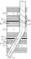
- FIG. Drawing 1 is a mimetic diagram for explaining the manufacturing method of the elongate stretched film concerning this embodiment.
- FIG. 1 is drawing which shows schematically the positional relationship of a elongate film and a heating apparatus in the said diagonal stretch apparatus, and the holding tool etc. are abbreviate
- the manufacturing method of the said elongate stretched film is the injection area
- the heating device 12 is formed with an injection port 14 capable of injecting hot air over the entire length in the width direction of the position where the long film 11 can travel in the oblique stretching device.
- the heating apparatus 12 is equipped with the injection area
- an injection port 14 capable of injecting hot air is formed over the entire length in the width direction at a position where the long film 11 can run in the oblique stretching device. It is preferable to adjust the injection region of the hot air by adjusting the injection region 13 where the hot air is injected by covering a part of the injection port 14 with the injection region adjusting unit 15 using the heating device 12. By doing so, since the hot air injection position can be more easily adjusted according to the running position of the long film 11, the long stretched film in which the variation in the orientation angle is sufficiently suppressed, It can be manufactured easily.
- region 13 is longer than the length of the width direction of the said elongate film 11, and shorter than the full length of the width direction of an oblique stretch apparatus. It is preferable to adjust the width. That is, as shown in FIG. 1, in the oblique stretching apparatus, a plurality of injection ports 14 capable of injecting hot air are arranged side by side over the entire length in the width direction of the position where the long film 11 can travel in the oblique stretching apparatus.
- the length in the longitudinal direction of the spray region 13 adjusted by the spray region adjusting unit 15 is longer than the length in the width direction of the long film 11, and It is preferably shorter than the total length in the width direction.
- the spray region 13 is more preferably longer than the width direction of the long film 11 and 2 m or less longer than the length of the long film 11 in the width direction. More preferably, the length is 400 mm or less longer than the length in the width direction. If the said injection
- hot air does not hit only a part of the long film, or hot air is not sprayed more than necessary to places other than the long film. That is, it is considered that the hot air sprayed from the heating device is suitably blown onto the long film.
- the jet region adjusting unit 15 has a mechanism that moves in the width direction (longitudinal direction) of the jet port 14 according to the travel position of the long film 11. That is, in the manufacturing method of the said elongate stretched film, the injection area
- the spray region adjusting unit 15 moves the center position in the width direction of the spray region 13 from the center position in the width direction of the long film 11 to the inner peripheral side and the outer peripheral side of the long film 11. It is preferable to shift the temperature to the lower one. By doing so, what the dispersion
- the inner peripheral side is a side portion having a shorter traveling distance of a gripping tool for gripping the long film when the long film is obliquely stretched.
- the outer peripheral side is a side portion opposite to the inner peripheral side. That is, the outer peripheral side is a side portion where the traveling distance of the gripping tool that grips the long film is longer. Specifically, it will be described later.
- a plurality of the heating devices 12 may be installed in parallel as shown in FIG. Specifically, for example, a plurality of heating devices each having one injection port may be installed in parallel. Further, the heating device 12 may have a plurality of injection ports 14 formed therein. And it is preferable that all the injection openings 14 can adjust the injection position of the hot air according to the running position of the long film. That is, it is preferable to adjust the injection region 13 as described above with respect to all the injection ports 14 formed in the heating device 12. Specifically, it is preferable that the injection region adjustment unit 15 is provided for all of the plurality of injection ports 14. By doing so, the dispersion
- the heating device 12 is not particularly limited.
- each injection port 14 is substantially parallel to the width direction of the oblique stretching device as shown in FIG.
- a plurality of heating devices in which one injection port 14 is formed are arranged in parallel.
- the heating apparatus currently formed so that the some injection port 14 may become substantially parallel to the width direction of a diagonal stretch apparatus may be sufficient.
- FIG. 2 is a schematic view showing an example of a method for producing a long stretched film according to the present embodiment.
- the region in which the long film travels in the oblique stretching apparatus includes a preheating zone (preheating region) 21, a stretching zone (stretching region) 22, and a heat setting zone (heat fixing region). ) 23.
- the preheating zone 21 is an area for preheating while transporting a long film, which is disposed on the inlet side of the oblique stretching apparatus.
- stretching zone 22 is an area
- the heat setting zone 23 is an area for heat-setting the long film that is arranged on the downstream side of the stretching zone 22 and is obliquely stretched. Each of these zones has a different temperature within the zone. The temperature of each zone will be described later.
- first partition wall 24 is provided between the preheating zone 21 and the stretching zone 22.
- second partition wall 25 is provided between the stretching zone 22 and the heat setting zone 23.
- FIG. 2 shows a case where the first partition wall 24 and the running direction (arrow direction) of the long film 11 are substantially perpendicular.
- substantially vertical indicates 90 ⁇ 5 °. That is, an angle ⁇ 1 formed by the first partition wall 24 and the running direction (arrow direction) of the long film 11 is 85 to 95 °.
- [theta] 1 is 90 [deg.] Is exemplified.
- FIG. 2 shows a case where the second partition wall 25 and the orientation axis 26 of the elongated film after oblique stretching are substantially parallel.
- substantially parallel indicates 0 ⁇ 5 °. That is, the angle ⁇ 2 formed by the second partition wall 25 and the orientation axis 26 of the long film after oblique stretching is ⁇ 5 to 5 °.
- ⁇ 2 is 0 ° is exemplified.
- the same stretching axis 26 of the elongated film 11 after oblique stretching has almost no deviation in the timing of entering the heat setting zone 23 from the stretching zone 22, so that the one in the width direction of the long film There is almost no temperature difference between one end and the other end. Therefore, there is almost no occurrence of uneven heating of the long film due to this timing shift. Therefore, it is not particularly necessary to shift the center position in the width direction of the ejection region 27 as described above from the center position in the width direction of the long film 11. That is, it is preferable that the center position of the ejection region 27 in the width direction and the center position of the long film 11 in the width direction coincide with each other.
- the center position in the width direction of the injection region 27 and the center position in the width direction of the long film 11 coincide with each other in all the injection ports.
- FIG. 3 is a schematic view showing another example of a method for producing a long stretched film according to the present embodiment.
- the region in which the long film travels in the oblique stretching apparatus has a preheating zone (preheating region) 21, a stretching zone (stretching region) 22, as shown in FIG. 2. And a heat setting zone (heat setting region) 23.
- a first partition wall 24 is provided between the preheating zone 21 and the stretching zone 22.
- a second partition wall 25 is provided between the stretching zone 22 and the heat setting zone 23.
- FIG. 3 shows a case where the first partition 24 and the running direction (arrow direction) of the long film 11 are not substantially perpendicular. That is, the case where the angle ⁇ 1 formed by the first partition wall 24 and the traveling direction (arrow direction) of the long film 11 is less than 85 ° or more than 95 ° is shown. Specifically, the case where ⁇ 1 is 45 ° is exemplified.
- the stretching zone 22 has a lower temperature than the preheating zone 21.
- the inner peripheral side enters the stretching zone 22 before the outer peripheral side.
- the injection region 33 in the injection port 31 existing closest to the stretching zone 22 is such that the inner peripheral side of the long film 11 is hotter than the outer peripheral side.
- the injection region adjusting unit 32 shift the hot air to a position where it can be injected. That is, it is preferable to shift the center position in the width direction of the spray region 33 from the center position in the width direction of the long film 11 to the inner peripheral side by the spray region adjusting unit 32.
- this transition is the injection region to a position where the temperature on the inner peripheral side is higher than that on the outer peripheral side if the temperature of the long film is substantially the same on the inner peripheral side and the outer peripheral side. 33 transitions.
- produces for the above reasons can be suppressed.
- produce around the 1st partition 24 between the preheating zone 21 and the extending
- FIG. 3 shows the case where the 2nd partition 25 and the orientation axis
- the same stretching axis 26 of the elongated film 11 after oblique stretching is displaced between the inner peripheral side and the outer peripheral side at the timing of entering the heat setting zone 23 from the stretching zone 22.
- the inner peripheral side enters the heat fixing zone 23 before the outer peripheral side.
- the temperature of the heat setting zone 23 is lower than that of the stretching zone 22.
- the inner peripheral side of the long film 11 is hotter than the outer peripheral side in the injection region 37 in the injection port 35 present in the position closest to the heat fixing zone 23 among the injection ports present in the stretching zone 22. It is preferable to cause the injection region adjusting unit 36 to shift to a position where such hot air can be injected.
- FIG. 4 is a schematic view showing another example of the method for producing a long stretched film according to the present embodiment.
- This long stretched film manufacturing method is different in that ⁇ 1 is larger and ⁇ 2 is smaller than the case shown in FIG. 3, as shown in FIG. Specifically, for example, ⁇ 1 is 70 ° and ⁇ 2 is 20 °. That is, this method for producing a long stretched film is a case where ⁇ 1 is less than 85 ° or more than 95 ° and ⁇ 2 is less than ⁇ 5 ° or more than 5 ° as shown in FIG. Thus, although ⁇ 1 and ⁇ 2 are different from those shown in FIG. 3, the injection region and the like are preferably the same as those shown in FIG.
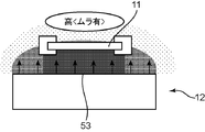
- FIG. 5 is a schematic view for explaining the heating state of the long film by the transition of the spray region in the method for producing a long stretched film according to the present embodiment.
- 5A is a schematic diagram illustrating a case where the center position in the width direction of the ejection region 53 is coincident with the center position in the width direction of the long film 11.
- FIG. 5B shows that the center position in the width direction of the spray region 53 extends from the center position in the width direction of the long film 11 toward the end in the width direction of the long film 11. It is the schematic which shows the case where 53 is transferred.
- FIG. 5 (b) is mentioned as an example when raising the temperature of an inner peripheral side.
- the long film 11 is heated from the center portion to the end portion of the injection region 53 defined by the injection region adjustment unit 55. This is thought to be due to a gradual decline in ability. Moreover, from this, when the injection region 53 is set widely irrespective of the travel position of the long film 11, the ability to heat the long film 11 is compared with the case shown in FIG. It is thought that it will fall. From this, it is considered that uneven heating is likely to occur in the long film 11. This is considered to be due to the following.
- FIG. 6 shows a schematic cross-sectional view of a heating device used in the method for producing a long stretched film according to this embodiment.
- the injection region 53 is defined by the injection region adjustment unit 55. That is, a part of the injection port is covered with the injection region adjustment unit 55.
- hot air generated in the device hits the injection region adjusting unit 55 and convects, and is injected only from the injection region 53. From this, even if the amount of hot air generated in the heating device 12 is the same, it is considered that the ability to heat the long film by the hot air jetted from the jet region 53 is enhanced. Moreover, it is thought that the fall of the capability to heat a long film is suppressed from the center part to the edge part of the injection area
- FIG. 7 is a schematic view showing an example of a method for producing a long stretched film when no injection region adjusting section is provided. This manufacturing method is the same as that shown in FIG. 2 except that the injection region adjustment unit is not provided.
- FIG. 8 is a schematic view showing another example of a method for producing a long stretched film in the case where the injection region adjusting unit is not provided. This manufacturing method is the same as that shown in FIG. 3 except that the injection region adjustment unit is not provided.
- FIG. 9 is a schematic cross-sectional view of the heating device when the injection region adjustment unit is not provided.
- This heating device is the same as the heating device shown in FIG. 6 except that it does not include an injection region adjustment unit. Moreover, in the manufacturing method shown in FIG.7 and FIG.8, the heating apparatus of the state shown in FIG. 9 is used.
- hot air is injected from the heating device 12 regardless of the running position of the long film. From this, it is considered that the ability to heat the long film by the hot air jetted from the heating device 12 is inferior to the case shown in FIG. That is, as described above, even if the amount of hot air generated by the heating device 12 is the same as that shown in FIG. 6, the ability to heat a long film by hot air jetted from the jet region 53 is It is thought that it becomes weaker than the case shown in FIG. Moreover, as shown in FIG. 9, the hot air generated in the heating device 12 is widely sprayed in directions other than the direction toward the long film. From these things, it is thought that the nonuniformity generate
- FIG. 10 and FIG. 11 are schematic diagrams for explaining each step of the method for producing a long stretched film according to the present embodiment.
- this is an example, and the present invention is not limited to this.
- a manufacturing apparatus for carrying out the method for manufacturing a long stretched film includes an oblique stretching apparatus 101, a film feeding apparatus 102, a film winding apparatus 103, transport rolls 104 and 105, an inner side ( Inner peripheral side) gripping tool travel support tool 106, outer (outer peripheral side) gripping tool travel support tool 107, and the like.
- the grip start point is indicated by reference numerals 108 and 109
- the grip release point is indicated by reference numerals 110 and 111.
- the step of forming a film is a step of forming a long original film containing a thermoplastic resin.
- the film forming step is performed by various means depending on the type of the thermoplastic resin, and the details will be described later.
- the long film formed in the film forming step is transferred into the oblique stretching apparatus from a specific direction different from the traveling direction of the stretched film, and both ends of the long film in the width direction are transferred.
- the angle with respect to the width direction of the film is an angle within the film plane. Since the slow axis is usually expressed in the stretching direction or a direction perpendicular to the stretching direction, in the manufacturing method according to this embodiment, the slow axis is at an angle of more than 0 ° and less than 90 ° with respect to the direction perpendicular to the running direction of the film.
- a long stretched film having such a slow axis can be produced by stretching at a desired angle. That is, in the method for producing a long stretched film of this embodiment, a long stretched film having a slow axis (orientation axis) at an angle of more than 0 ° and less than 90 ° with respect to the width direction of the film is produced.
- the angle formed by the width direction of the long stretched film and the slow axis that is, the orientation angle, can be arbitrarily set to a desired angle in the range of more than 0 ° and less than 90 °.
- the film feeding device 102 can slide and turn so that the film can be fed at a predetermined angle with respect to the entrance of the oblique stretching device 101.
- the film feeding device 102 is slidable, and it is preferable that the film can be fed to the entrance of the oblique stretching device by the transport direction changing device.
- the transport direction changing device By adopting such a configuration for the film feeding device 102 and the transport direction changing device, it is possible to finely control the film feeding position and angle, and to produce a long stretched film with small variations in film thickness and optical value. Can be obtained. Further, by making the film feeding device 102 and the transport direction changing device movable, it is possible to effectively prevent the gripping tool from being caught in the film.
- the film feeding apparatus 102 may be configured separately from the oblique stretching apparatus 101 or may be configured integrally.
- a long film before oblique stretching is wound around a core after film formation and loaded into a film feeding device 102 so that the long film is fed from the film feeding device 102. It is.
- the film feeding device 102 feeds the long film before the oblique stretching to the oblique stretching device 101 without winding the long film.
- the transport roll 104 is a roll that feeds the film fed from the film feeding device 102 to the grip start points 108 and 109 shown in FIGS.
- the number of the transport rolls 105 is not particularly specified, and a slitter process for cutting the film end part may be provided in the middle of disposing the transport rolls. Moreover, you may provide the static elimination apparatus for neutralizing a film before and behind arrangement
- an oblique stretching apparatus is used to impart an oblique orientation to the long film.
- the oblique stretching apparatus is not particularly limited as long as it is a manufacturing apparatus capable of realizing the oblique stretching process in the manufacturing method according to the present embodiment.
- the long film is obliquely stretched in a direction greater than 0 ° and less than 90 ° with respect to the width direction while gripping and transporting both ends of the long film made of thermoplastic resin.
- the oblique stretching apparatus includes a heating device that injects hot air onto the long film during the oblique stretching.
- the oblique stretching apparatus arbitrarily changes the running position of the long film in order to obliquely stretch the long film in an arbitrary direction greater than 0 ° and less than 90 ° with respect to the width direction. It is configured to be possible. Further, as described above, the heating device is capable of adjusting the hot air injection position according to the travel position of the long film.
- diagonal stretch can be given to the elongate film which consists of a thermoplastic resin.
- corner can be fully suppressed at the time of the diagonal stretch. Therefore, when a long stretched film is produced using such an oblique stretching apparatus, a long stretched film that is obliquely stretched and has a sufficiently suppressed variation in orientation angle is produced. Can do. That is, a film in which the variation in the orientation angle in the width direction of the obtained long stretched film is sufficiently suppressed can be obtained. This is considered to be because the heating device can improve the uniformity of the heating state of the long film when the long film is obliquely stretched by the oblique stretching device.
- the oblique stretching apparatus used in the present embodiment is preferably a film stretching apparatus that can freely set the orientation angle of the film by variously changing the path pattern. Furthermore, it is preferable that the film stretching apparatus is capable of highly accurately orienting the orientation axis of the film across the width direction of the film and controlling the film thickness and retardation with high precision.
- FIG. 12 is a schematic view showing an example of a path pattern of an oblique stretching apparatus used in the method for producing a long stretched film according to this embodiment.
- this is an example, and the present invention is not limited to this.
- the feeding direction D1 of the long film is different from the winding direction D2 of the elongated film after stretching, and forms a feeding angle ⁇ i.
- the feeding angle ⁇ i can be arbitrarily set to a desired angle in the range of more than 0 ° and less than 90 °.
- the long film is gripped at both ends by the left and right grippers (a pair of grippers) at the entrance of the oblique stretching apparatus (position A in FIG. 12), and travels as the grippers travel.
- the left and right gripping tools are left and right gripping tools Ci that are opposed to a direction substantially perpendicular to the traveling direction of the long film (feeding direction D1) at the entrance of the oblique stretching apparatus (position A in FIG. 12).
- the left and right grippers Ci and Co travel on the left and right asymmetric gripper travel support tools Ri and Ro, and release the film gripped at the position at the end of stretching (position B in FIG. 12).
- the left and right gripping tools opposed at the entrance of the oblique stretching apparatus travel on the Ri side as they travel on the left and right asymmetric gripping tool travel support tools Ri and Ro.
- Ci is a positional relationship that advances relative to the gripping tool Co traveling on the Ro side.
- the gripping tools Ci and Co that are opposed to the direction D1 of the long film at the entrance A (the grip start position by the film gripping tool) A are stretched by the long film.
- the straight line connecting the grippers Ci and Co is inclined by an angle ⁇ L with respect to a direction substantially perpendicular to the film winding direction D2.
- the long film is obliquely stretched in the direction of ⁇ L.
- substantially vertical indicates that the angle is in a range of 90 ⁇ 5 °.
- the manufacturing method according to the present embodiment is performed using an oblique stretching apparatus capable of oblique stretching.
- the oblique stretching apparatus can heat the long film to an arbitrary temperature at which stretching can be performed.
- the oblique stretching device includes a heating zone, a pair of gripping tool travel support tools on the left and right of the gripping tool for transporting the film, a number of gripping tools traveling on the gripping tool travel support tool, and the gripping A gripping tool travel support for supporting the travel of the tool.
- the both ends of the long film sequentially supplied to the inlet of the oblique stretching apparatus are gripped by a gripping tool, the long film is guided into the heating zone, and the film is released from the gripping tool at the outlet of the oblique stretching apparatus.
- the film released from the gripping tool is wound around the core.
- Each of the pair of gripping tool running support tools has an endless continuous track, and the gripping tool that has released the grip of the film at the exit portion of the tenter travels outside and is sequentially returned to the inlet portion. .
- the gripping tool travel support tool may be, for example, a form in which an endless chain whose path is regulated by a guide rail or a gear is provided with a gripping tool, or a form in which an endless guide rail is provided with a gripping tool. It may be. That is, in the present invention, the gripping tool travel support tool may be, for example, an endless guide rail provided with an endless chain, or may be an endless guide rail provided with an endless chain. An endless guide rail without a chain may be used.
- the gripper travel support tool does not include a chain, the gripper travels along the path of the gripper travel support tool itself.
- the gripper travel support tool includes the chain, the gripper travel support tool travels along the path of the gripper travel support tool. Run.
- the path pattern of the oblique stretching apparatus has an asymmetric shape on the left and right, and the path pattern is adjusted manually or automatically according to the orientation angle ⁇ , the stretching ratio, etc. given to the long stretched film to be manufactured. It can be done.
- the position of each path part and the path connection part can be freely set and the path pattern can be arbitrarily changed.
- the route pattern may be a rail pattern when the gripping tool travel support tool is a guide rail.
- the gripping tool of the oblique stretching apparatus travels at a constant speed with a constant distance from the front and rear gripping tools.
- the traveling speed of the gripping tool can be selected as appropriate, but is usually 1 to 150 m / min.
- the traveling speed of the gripping tool of the oblique stretching apparatus is set to a relatively high speed of 15 to 150 m / min, the production efficiency is increased.
- the stretching stress becomes high, and it is difficult to heat the long film uniformly before stretching because it is traveling at high speed. There is a tendency to come.
- it is the manufacturing method which concerns on this embodiment even if it is such a speed
- the traveling speed of the gripping tool is preferably 15 to 150 m / min as described above, but more preferably 40 to 150 m / min. If it is a production method of a general long stretched film, when producing a long stretched film at a running speed in such a range, the stretch rate when obliquely stretching the long film becomes too high, There is a tendency that the development of optical characteristics becomes remarkable. For this reason, in order to sufficiently suppress the occurrence of uneven alignment, highly accurate temperature control or the like is required. If it is the manufacturing method which concerns on this embodiment, even if it is such a speed
- the difference in travel speed between the pair of left and right gripping tools is usually 1% or less, preferably 0.5% or less, more preferably 0.1% or less of the travel speed. This is because if there is a difference in the traveling speed between the left and right sides of the film at the exit of the stretching process, wrinkles and deviations will occur at the exit of the stretching process. Because it is. In general stretching devices, etc., there are speed irregularities that occur in the order of seconds or less depending on the period of the sprocket teeth that drive the chain, the frequency of the drive motor, etc. It does not correspond to the speed difference described in the form.
- a gripping tool traveling support that regulates the trajectory of the gripping tool is often required to have a high bending rate, particularly at a location where the film is transported obliquely.
- the long film is sequentially gripped at both ends by the left and right grippers and travels as the grippers travel.
- the left and right gripping tools facing the direction substantially perpendicular to the film traveling direction D1 at the entrance of the oblique stretching apparatus (position A in FIG. 12) travel on the gripping tool travel support tool that is asymmetrical and preheat. It passes through a heating zone having a zone, a stretching zone, and a heat setting zone (fixing zone).
- the preheating zone refers to a section where the distance between the gripping tools gripping both ends is kept constant at the heating zone entrance.
- the stretching zone refers to the interval until the gap between the gripping tools gripping both ends starts to reach a predetermined interval.
- the oblique stretching as described above is performed, but the stretching may be performed in the longitudinal direction or the transverse direction before and after the oblique stretching as necessary.
- the film can be stretched in an oblique direction in the stretching zone.
- the stretching is not limited to the stretching in the oblique direction. Later, it may be further stretched in the width direction.
- the heat setting zone refers to the section in which the gripping tools at both ends run parallel to each other during the period when the spacing between the gripping tools after the stretching zone becomes constant again. You may pass through the area (cooling zone) by which the temperature in a zone is set to below the glass transition temperature Tg degreeC of the thermoplastic resin which comprises a elongate film, after passing through a heat setting zone. At this time, in consideration of shrinkage of the film due to cooling, a path pattern that narrows the gap between the opposing grippers in advance may be used.
- transverse stretching and longitudinal stretching may be performed as necessary in the steps before and after introducing the long film into the oblique stretching apparatus.
- the temperature of each zone is Tg to Tg + 30 ° C.
- the temperature of the stretching zone is Tg to Tg + 30 ° C.
- the temperature of the heat setting zone is Tg to Tg + 30 ° C. with respect to the glass transition temperature Tg of the thermoplastic resin. It is preferable to set Tg to Tg + 20 ° C. and the temperature of the cooling zone to Tg ⁇ 30 to Tg ° C. Moreover, it is preferable to make it the temperature of each zone become low in order of a preheating zone, an extending
- the gripping tool Ci traveling on the Ri side proceeds ahead of the gripping tool Co traveling on the Ro side. Then, on the Ro side with respect to the preceding Ri side, the long film is released from the gripping tool (clip) at the position B after the Ri side. That is, the Ro side end of the long film has a longer residence time in the heating zone than the Ri side end. For this reason, the Ro side thickness of the long film may be thinner than the Ri side thickness of the long film.
- a temperature difference is applied in the width direction of the film when passing through the preheating zone, the stretching zone, and the heat setting zone, and the Ro side end of the long film, the Ri side end,
- the film thickness difference can be eliminated by adjusting the amount of heat received to approximately the same amount and producing a long stretched film.
- the manufacturing method which concerns on this embodiment adjusts the opening degree of the nozzle that sends warm air into the temperature-controlled room to make a difference in the width direction, or control the heating by arranging the heaters in the width direction.
- a known method such as can be used.
- the thickness nonuniformity of the obtained elongate stretched film can be suppressed more. That is, even if it does not use said well-known method, according to the manufacturing method which concerns on this embodiment, the elongate stretched film by which the thickness nonuniformity was suppressed more can be obtained. Also from this point, the manufacturing method according to the present embodiment is preferable.
- the lengths of the preheating zone, the stretching zone and the heat setting zone can be appropriately selected.
- the length of the preheating zone is usually 100 to 150%, and the length of the heat setting zone is usually 50 to the length of the stretching zone. 100%.
- each zone according to the present embodiment is based on the heating method as described above.
- the stretch ratio (W / W0) in the oblique stretching step is preferably 1.3 to 3.0, more preferably 1.5 to 2.8. When the draw ratio is in this range, it is preferable because uneven thickness in the width direction is reduced. In the stretching zone of the oblique stretching apparatus, if the stretching temperature is differentiated in the width direction, it is possible to further improve the width direction thickness unevenness.
- W0 represents the width of the film before stretching
- W represents the width of the film after stretching.
- the step (winding step) of winding the long stretched film in the manufacturing method according to this embodiment is a step of winding the long stretched film after the oblique stretching step. Below, the film winding apparatus used for a winding process is demonstrated.
- the film winding device 103 is formed so that the film can be pulled at a predetermined angle with respect to the outlet of the oblique stretching device, thereby finely controlling the take-up position and angle of the long stretched film. It becomes possible to do. Moreover, it becomes possible to obtain a long stretched film with small variations in film thickness and optical value. Therefore, the occurrence of wrinkles in the long stretched film can be effectively prevented, and the film winding property is improved, so that the film can be wound up in a long length.
- the take-up tension T (N / m) of the long stretched film after stretching is adjusted between 100 N / m ⁇ T ⁇ 300 N / m, preferably 150 N / m ⁇ T ⁇ 250 N / m. It is preferable.
- the take-up tension is 100 N / m or less, sagging and wrinkles of the long stretched film tend to occur, and the retardation and the profile in the width direction of the orientation axis may deteriorate.
- the take-up tension is 300 N / m or more, the variation in the orientation angle in the width direction tends to be deteriorated, and thus the width yield (taken efficiency in the width direction) may be deteriorated.
- the fluctuation of the take-up tension T it is preferable to control the fluctuation of the take-up tension T with an accuracy of less than ⁇ 5%, preferably less than ⁇ 3%.
- the variation in the take-up tension T is ⁇ 5% or more, there is a tendency that variations in the optical characteristics in the width direction and the flow direction increase.
- the load applied to the first roll at the outlet of the oblique stretching apparatus that is, the tension of the long stretched film is measured, and the value is made constant.
- Examples of the method for measuring the load include a method in which a load cell is attached to a bearing portion of a roll and a load applied to the roll, that is, a tension of a long stretched film is measured.
- a load cell a known tensile type or compression type can be used.
- the long film after the oblique stretching is released from the oblique stretching device outlet after being held by the gripper, and is wound up around the winding core (winding roll) to form a wound body of the long stretched film.
- Winding core winding roll
- both ends of the film held by the holding tool of the oblique stretching apparatus may be cut before winding on the winding roll.
- the cutting may be performed at a time or may be performed in a plurality of times.
- both ends of a long stretched film are cut
- the masking film may be overlapped and wound up at the same time, or at least one of the long stretched films, preferably while winding tape or the like on both ends. You may take it.
- the masking film is not particularly limited as long as it can protect the film, and examples thereof include a polyethylene terephthalate film, a polyethylene film, and a polypropylene film.
- a film thickness meter or an optical value measuring device capable of online measurement may be arranged in the middle of the arrangement of the transport roll.
- a neutralization device for neutralizing the long stretched film may be provided, or may be installed before the winding device.
- a well-known thing can be used for the said static elimination apparatus without a restriction
- the manufacturing apparatus of the elongate stretched film which concerns on other embodiment of this invention will not be specifically limited if it is a manufacturing apparatus which can implement
- a manufacturing apparatus provided with the oblique stretching apparatus can be used.
- thermoplastic resin and film forming method As the thermoplastic resin that can be used in the present embodiment, polycarbonate resin, polyether sulfone resin, polyethylene terephthalate resin, polyimide resin, polymethyl methacrylate resin, polysulfone resin, polyarylate resin, Examples thereof include a polyethylene resin, a polyvinyl chloride resin, an olefin polymer resin having an alicyclic structure in the molecule, and a cellulose ester resin.
- polycarbonate resins, olefin polymer resins having an alicyclic structure in the molecule, and cellulose ester resins are preferable from the viewpoints of transparency and mechanical strength.
- an olefin polymer resin and a cellulose ester resin having an alicyclic structure in the molecule, which can easily adjust the phase difference in the case of an optical film, are more preferable.
- the structure about the olefin polymer-type resin (alicyclic olefin polymer-type resin) which has an alicyclic structure in a molecule
- Alicyclic olefin polymer resin examples include cyclic olefin random multi-component copolymers described in JP-A-5-310845, hydrogenated polymers described in JP-A-5-97978, and JP-A-11. And thermoplastic dicyclopentadiene ring-opening polymers described in JP-A-124429 and hydrogenated products thereof.
- the olefin polymer resin having an alicyclic structure in the molecule will be described more specifically.
- the alicyclic olefin polymer-based resin is a polymer having an alicyclic structure such as a saturated alicyclic hydrocarbon (cycloalkane) structure or an unsaturated alicyclic hydrocarbon (cycloalkene) structure in the molecule.
- the number of carbon atoms constituting the alicyclic structure is not particularly limited, but when it is usually in the range of 4 to 30, preferably 5 to 20, more preferably 5 to 15, the mechanical strength,
- the properties of heat resistance and film formability are highly balanced and suitable.
- the proportion of the repeating unit containing the alicyclic structure in the alicyclic olefin polymer may be appropriately selected, but is preferably 55% by mass or more, more preferably 70% by mass or more, and particularly preferably 90% by mass. That's it.
- the ratio of the repeating unit having an alicyclic structure in the alicyclic polyolefin resin is within this range, the transparency and heat resistance of an optical material such as a long stretched film obtained by the production method according to the present embodiment are improved. This is preferable.
- olefin polymer resins having an alicyclic structure in the molecule examples include norbornene resins, monocyclic olefin resins, cyclic conjugated diene resins, vinyl alicyclic hydrocarbon resins, and hydrides thereof. Can be mentioned. Among these, norbornene-based resins can be suitably used because of their good transparency and moldability.
- Examples of the norbornene-based resin include a ring-opening polymer of a monomer having a norbornene structure, a ring-opening copolymer of a monomer having a norbornene structure and another monomer, a hydride thereof, and a norbornene structure.
- a ring-opening (co) polymer hydride of a monomer having a norbornene structure is particularly preferable from the viewpoints of transparency, moldability, heat resistance, low hygroscopicity, dimensional stability, and lightness. It can be used suitably.
- Monomers having a norbornene structure in the molecule include bicyclo [2.2.1] hept-2-ene (common name: norbornene), tricyclo [4.3.0.12,5] deca-3,7. -Diene (common name: dicyclopentadiene), 7,8-benzotricyclo [4.3.12,5] dec-3-ene (common name: methanotetrahydrofluorene), tetracyclo [4.4.0 .12,5.17,10] dodec-3-ene (common name: tetracyclododecene), derivatives of these compounds (for example, those having a substituent in the ring), and the like.
- examples of the substituent include an alkyl group, an alkylene group, and a polar group. Moreover, these substituents may be the same or different and a plurality may be bonded to the ring. Monomers having a norbornene structure in the molecule can be used singly or in combination of two or more.
- Examples of polar groups include heteroatoms or atomic groups having heteroatoms.
- Examples of the hetero atom include an oxygen atom, a nitrogen atom, a sulfur atom, a silicon atom, and a halogen atom.
- Specific examples of the polar group include a carboxyl group, a carbonyloxycarbonyl group, an epoxy group, a hydroxyl group, an oxy group, an ester group, a silanol group, a silyl group, an amino group, a nitrile group, and a sulfone group.
- monomers capable of ring-opening copolymerization with a monomer having a norbornene structure in the molecule include monocyclic olefins such as cyclohexene, cycloheptene, and cyclooctene and derivatives thereof; and cyclohexadiene and cycloheptadiene. Cyclic conjugated dienes such as and derivatives thereof; and the like.
- a ring-opening polymer of a monomer having a norbornene structure in the molecule and a ring-opening copolymer of the monomer having a norbornene structure with another monomer copolymerizable with the monomer have a known ring-opening property. It can be obtained by (co) polymerization in the presence of a polymerization catalyst.
- Examples of other monomers that can be addition copolymerized with a monomer having a norbornene structure in the molecule include ⁇ -olefins having 2 to 20 carbon atoms such as ethylene, propylene, and 1-butene, and derivatives thereof; And cycloolefins such as cyclobutene, cyclopentene, and cyclohexene, and derivatives thereof; and non-conjugated dienes such as 1,4-hexadiene, 4-methyl-1,4-hexadiene, and 5-methyl-1,4-hexadiene. It is done.
- These monomers can be used alone or in combination of two or more. Among these, ⁇ -olefin is preferable, and ethylene is more preferable.
- An addition polymer of a monomer having a norbornene structure in the molecule and an addition copolymer with another monomer that can be copolymerized with a monomer having a norbornene structure in the molecule are known monomers. It can be obtained by polymerization in the presence of an addition polymerization catalyst.
- Hydrogenation product of a ring-opening polymer of a monomer having a norbornene structure in the molecule, ring-opening copolymerization of the monomer having a norbornene structure in the molecule and other monomers capable of ring-opening copolymerization A hydrogenated product of a polymer, an addition polymer of a monomer having a norbornene structure in the molecule, and a monomer having a norbornene structure in the molecule and another monomer copolymerizable therewith
- a known hydrogenation catalyst containing a transition metal such as nickel or palladium is added to a solution of these polymers, and the carbon-carbon unsaturated bond is preferably hydrogenated by 90% or more. Can be obtained.
- X bicyclo [3.3.0] octane-2,4-diyl-ethylene structure and Y: tricyclo [4.3.0.12,5] decane-7, 9-diyl-ethylene structure
- the content of these repeating units is 90% by mass or more with respect to the entire repeating units of the norbornene resin
- the content ratio of X and the content ratio of Y The ratio is preferably 100: 0 to 40:60 in terms of mass ratio of X: Y.
- the molecular weight used for the norbornene resin is appropriately selected according to the purpose of use, but is converted to polyisoprene (solvent) measured by gel permeation chromatography using cyclohexane (toluene if the thermoplastic resin does not dissolve) as a solvent.
- the weight average molecular weight (Mw) in terms of polystyrene is usually 10,000 to 100,000, preferably 15,000 to 80,000, more preferably 20,000 to 50,000.
- the weight average molecular weight is in such a range, the long stretched film obtained by the production method according to the present embodiment, and the mechanical strength and molding processability of the optical material obtained using the long stretched film are Highly balanced and suitable.
- the glass transition temperature of the norbornene-based resin may be appropriately selected depending on the purpose of use, but is preferably 80 ° C. or higher, more preferably in the range of 100 to 250 ° C.
- the glass transition temperature is in such a range, the long stretched film obtained by the production method according to the present embodiment and the optical material obtained using the long stretched film can be deformed in use at high temperatures. No stress is generated and the durability can be improved.
- the molecular weight distribution (weight average molecular weight (Mw) / number average molecular weight (Mn)) of the norbornene-based resin is not particularly limited, but is usually 1 to 10, preferably 1.1 to 4, more preferably 1.2 to 3. The range is 5.
- the absolute value of the photoelastic coefficient C of norbornene-based resin is preferably 10 ⁇ 10 -12 Pa -1 or less, more preferably 7 ⁇ 10 -12 Pa -1 or less, 4 ⁇ 10 -12 Pa Particularly preferably, it is ⁇ 1 or less.
- thermoplastic resin used in this embodiment is a colorant such as a pigment or dye, a fluorescent brightener, a dispersant, a heat stabilizer, a light stabilizer, an ultraviolet absorber, an antistatic agent, an antioxidant, a lubricant, and a solvent. Or the like may be appropriately blended.
- a colorant such as a pigment or dye, a fluorescent brightener, a dispersant, a heat stabilizer, a light stabilizer, an ultraviolet absorber, an antistatic agent, an antioxidant, a lubricant, and a solvent. Or the like may be appropriately blended.
- the content of the residual volatile component in the stretched film of norbornene resin is not particularly limited, but is preferably 0.1% by mass or less, more preferably 0.05% by mass or less, and further preferably 0.02% by mass or less. It is.
- the content of the volatile component in such a range, the dimensional stability can be improved, and the temporal change of Re and Rth can be reduced.
- the deterioration of the optical film, polarizing plate or organic electroluminescence display device obtained by using the long stretched film obtained by the production method according to this embodiment can be suppressed, and the display on the display device can be stably displayed over the long term. Can keep good.
- a residual volatile component is a substance having a molecular weight of 200 or less contained in a trace amount in a long film, and examples thereof include a residual monomer and a solvent.
- the content of residual volatile components can be quantified by analyzing the film by gas chromatography as the sum of substances having a molecular weight of 200 or less contained in the long film.
- the saturated water absorption rate of the stretched film of norbornene resin is preferably 0.03% by mass or less, more preferably 0.02% by mass or less, and particularly preferably 0.01% by mass or less.
- the saturated water absorption is within the above range, the change with time of Re and Rth can be reduced.
- the deterioration of the optical film, polarizing plate or organic electroluminescence display device obtained by using the long stretched film obtained by the production method according to this embodiment can be suppressed, and the display on the display device can be stably displayed over the long term. Can keep good.
- the saturated water absorption is a value expressed as a percentage of the mass of the test piece before immersion, after the film specimen is immersed in water at a constant temperature for a certain period of time. Usually, it is measured by immersing in 23 ° C. water for 24 hours.
- the saturated water absorption rate in the stretched film of the present invention can be adjusted to the above value by, for example, reducing the amount of polar groups in the thermoplastic resin, but is preferably a resin having no polar groups. Is desired.
- melt forming method of olefin polymer resin As a method for forming a film using the preferred norbornene-based resin described above, a solution casting method or a melt extrusion method is preferred. Examples of the melt extrusion method include an inflation method using a die, but a method using a T die is preferable in terms of excellent productivity and thickness accuracy.
- the extrusion molding method using a T-die is a method for maintaining retardation and orientation by a method of keeping a molten thermoplastic resin in a stable state when closely contacting a cooling drum as described in JP-A-2004-233604. Films with favorable optical properties such as corners can be produced.
- a sheet-like thermoplastic resin extruded from a die is brought into close contact with a cooling drum under a pressure of 50 kPa or less; 2) melting When producing a long film by extrusion, the enclosure member covers from the die opening to the first cooling drum that is in close contact, and the distance from the enclosure member to the die opening or the first contact cooling drum is 100 mm or less.
- Method 3 Method of heating the temperature of the atmosphere within 10 mm to a specific temperature from the sheet-like thermoplastic resin extruded from the die opening when producing a long film by the melt extrusion method; A sheet-like thermoplastic resin extruded from a die so as to satisfy the above condition is brought into close contact with a cooling drum under a pressure of 50 kPa or less; A method in which a wind having a speed difference of 0.2 m / s or less from the take-up speed of the cooling drum that is first brought into close contact with the sheet-like thermoplastic resin extruded from the die opening is produced. It is done.
- the long film containing the above olefin polymer resin may be a single layer or a laminated film of two or more layers.
- the laminated film can be obtained by a known method such as a coextrusion molding method, a co-casting molding method, a film lamination method, or a coating method. Of these, the coextrusion molding method and the co-casting molding method are preferable.
- Cellulose ester resin A preferable cellulose ester-based resin film contains cellulose acylate satisfying the following formulas (1) and (2) and contains a compound represented by the following general formula (A). Can be mentioned.
- L 1 and L 2 each independently represent a single bond or a divalent linking group.
- L 1 and L 2 include structures represented by the following formulas. (The following R represents a hydrogen atom or a substituent.)
- L 1 and L 2 are preferably —O—, —COO—, and —OCO—.
- R 1 , R 2 and R 3 each independently represent a substituent.
- substituent represented by R 1 , R 2 and R 3 include a halogen atom (fluorine atom, chlorine atom, bromine atom, iodine atom, etc.), alkyl group (methyl group, ethyl group, n-propyl group, Isopropyl group, tert-butyl group, n-octyl group, 2-ethylhexyl group, etc.), cycloalkyl group (cyclohexyl group, cyclopentyl group, 4-n-dodecylcyclohexyl group, etc.), alkenyl group (vinyl group, allyl group, etc.) , Cycloalkenyl groups (2-cyclopenten-1-yl, 2-cyclohexen-1-yl group, etc.), alkynyl groups (ethynyl group, propargyl group, etc.),
- R 1 and R 2 are preferably a substituted or unsubstituted phenyl group or a substituted or unsubstituted cyclohexyl group. More preferred are a phenyl group having a substituent and a cyclohexyl group having a substituent, and further preferred are a phenyl group having a substituent at the 4-position and a cyclohexyl group having a substituent at the 4-position.
- R 3 is preferably a hydrogen atom, halogen atom, alkyl group, alkenyl group, aryl group, heterocyclic group, hydroxyl group, carboxyl group, alkoxy group, aryloxy group, acyloxy group, cyano group, amino group, More preferably, they are a hydrogen atom, a halogen atom, an alkyl group, a cyano group, and an alkoxy group.
- Wa and Wb represent a hydrogen atom or a substituent.
- Wa and Wb may be bonded to each other to form a ring, and
- at least one of Wa and Wb may have a ring structure.
- at least one of Wa and Wb may be an alkenyl group or an alkynyl group.
- substituent represented by Wa and Wb include halogen atoms (fluorine atom, chlorine atom, bromine atom, iodine atom, etc.), alkyl groups (methyl group, ethyl group, n-propyl group, isopropyl group, tert- Butyl group, n-octyl group, 2-ethylhexyl group, etc.), cycloalkyl group (cyclohexyl group, cyclopentyl group, 4-n-dodecylcyclohexyl group, etc.), alkenyl group (vinyl group, allyl group, etc.), cycloalkenyl group ( 2-cyclopenten-1-yl, 2-cyclohexen-1-yl group, etc.), alkynyl group (ethynyl group, propargyl group etc.), aryl group (phenyl group, p-tolyl group, naphthyl group etc.),
- Etc. mercapto group, alkylthio group (methylthio group, ethylthio group, n-hexadecylthio group, etc.), arylthio group (phenylthio group, p-chlorophenylthio group, m-methoxyphenylthio group, etc.), sulfamoyl group (N-ethylsulfide group, etc.) Famoyl group, N- (3-dodecyloxypropyl) sulfamoyl group, N, N-dimethylsulfamoyl group, N-acetylsulfamoyl group, N-benzoylsulfamoyl group, N- (N'phenylcarbamoyl) Sulfamoyl Group), sulfo group, acyl group (acetyl group, pivaloylbenzoyl group, etc.), carbamoyl
- Wa and Wb are bonded to each other to form a ring, it is preferably a nitrogen-containing 5-membered ring or a sulfur-containing 5-membered ring, particularly preferably represented by the following general formula (1) or general formula (2). It is a compound.
- a 1 and A 2 each independently represent —O—, —S—, —NRx— (Rx represents a hydrogen atom or a substituent) or —CO—.
- Rx represents a hydrogen atom or a substituent
- the example of the substituent represented by Rx is synonymous with the specific example of the substituent represented by said Wa and Wb.
- Rx is preferably a hydrogen atom, an alkyl group, an aryl group, or a heterocyclic group.
- X represents a nonmetallic atom belonging to Groups 14-16.
- Rc, Rd, and Re represent substituents, and examples thereof are synonymous with specific examples of the substituents represented by Wa and Wb.
- L 1, L 2, R 1 , R 2, R 3, n is L 1, L 2, R 1 , same meanings as R 2, R 3, n in the general formula (A).
- Q 1 is —O—, —S—, —NRy— (Ry represents a hydrogen atom or a substituent), —CRaRb— (Ra and Rb represent a hydrogen atom or a substituent) or Represents —CO—.
- Ry, Ra, and Rb represent substituents, and examples are synonymous with specific examples of the substituents represented by Wa and Wb.
- Y represents a substituent
- Examples of the substituent represented by Y are the same as the specific examples of the substituent represented by Wa and Wb.
- Y is preferably an aryl group, a heterocyclic group, an alkenyl group, or an alkynyl group.
- Examples of the aryl group represented by Y include a phenyl group, a naphthyl group, an anthryl group, a phenanthryl group, and a biphenyl group.
- a phenyl group and a naphthyl group are preferable, and a phenyl group is more preferable.
- heterocyclic group examples include heterocyclic groups containing at least one hetero atom such as a nitrogen atom, an oxygen atom, a sulfur atom such as a furyl group, a pyrrolyl group, a thienyl group, a pyridinyl group, a thiazolyl group, and a benzothiazolyl group.
- a heterocyclic group containing at least one hetero atom such as a nitrogen atom, an oxygen atom, a sulfur atom such as a furyl group, a pyrrolyl group, a thienyl group, a pyridinyl group, a thiazolyl group, and a benzothiazolyl group.
- Group, pyrrolyl group, thienyl group, pyridinyl group and thiazolyl group are preferred.
- aryl groups or heterocyclic groups may have at least one substituent.
- substituents include a halogen atom, an alkyl group having 1 to 6 carbon atoms, a cyano group, a nitro group, and 1 to 6 alkylsulfinyl groups, alkylsulfonyl groups having 1 to 6 carbon atoms, carboxyl groups, fluoroalkyl groups having 1 to 6 carbon atoms, alkoxy groups having 1 to 6 carbon atoms, alkylthio groups having 1 to 6 carbon atoms, 1 carbon atom N-alkylamino group having 6 to 6, N, N-dialkylamino group having 2 to 12 carbon atoms, N-alkylsulfamoyl group having 1 to 6 carbon atoms, N, N-dialkylsulfur group having 2 to 12 carbon atoms
- substituent include a moyl group.
- L 1, L 2, R 1 , R 2, R 3, n is L 1, L 2, R 1 , same meanings as R 2, R 3, n in the general formula (A).
- Q 3 represents ⁇ N— or ⁇ CRz— (Rz represents a hydrogen atom or a substituent), and Q 4 represents a nonmetallic atom belonging to Groups 14-16.
- Z represents a nonmetallic atom group that forms a ring with Q 3 and Q 4 .
- the ring formed from Q 3 , Q 4 and Z may be further condensed with another ring.
- the ring formed from Q 3 , Q 4 and Z is preferably a nitrogen-containing 5-membered ring or 6-membered ring condensed with a benzene ring.
- L 1, L 2, R 1 , R 2, R 3, n is L 1, L 2, R 1 , same meanings as R 2, R 3, n in the general formula (A).
- Wa and Wb is an alkenyl group or an alkynyl group
- a vinyl group having a substituent and an ethynyl group are preferable.
- the compound represented by general formula (3) is particularly preferable.
- the compound represented by the general formula (3) is superior in heat resistance and light resistance to the compound represented by the general formula (1), and is an organic solvent compared to the compound represented by the general formula (2).
- the solubility with respect to and the compatibility with a polymer are favorable.
- the compound represented by the general formula (A) according to the present invention can be contained by appropriately adjusting the amount for imparting desired wavelength dispersibility and anti-bleeding property.
- the content is preferably 1 to 15% by mass, and particularly preferably 2 to 10% by mass. If it is in this range, sufficient wavelength dispersibility and anti-bleeding property can be imparted to the cellulose derivative of the present invention.
- the compound represented by General Formula (A), General Formula (1), General Formula (2), and General Formula (3) can be performed with reference to a known method. Specifically, it can be synthesized with reference to Journal of Chemical Crystallography (1997); 27 (9); 512-526) JP 2010-31223 A, JP 2008-107767 A, and the like.
- the cellulose acylate film used in the production method according to the present embodiment contains cellulose acylate as a main component.
- the cellulose acylate film preferably contains cellulose acylate in the range of 60 to 100% by mass with respect to 100% by mass of the total mass of the film.
- the total acyl group substitution degree of cellulose acylate is 2 or more and less than 3, and more preferably 2.2 to 2.7.
- cellulose acylate examples include esters of cellulose and aliphatic carboxylic acids and / or aromatic carboxylic acids having about 2 to 22 carbon atoms, and in particular, esters of cellulose and lower fatty acids having 6 or less carbon atoms. Preferably there is.
- the acyl group bonded to the hydroxyl group of cellulose may be linear or branched, and may form a ring. Furthermore, another substituent may be substituted.
- the degree of substitution is the same, birefringence decreases when the number of carbon atoms described above is large. Therefore, the number of carbon atoms is preferably selected from acyl groups having 2 to 6 carbon atoms.
- the degree of propionyl substitution and the degree of butyryl substitution Is a sum of 0 or more and less than 3.
- the cellulose acylate preferably has 2 to 4 carbon atoms, more preferably 2 to 3 carbon atoms.
- cellulose acylate includes propionate group, butyrate group or phthalyl group in addition to acetyl group such as cellulose acetate propionate, cellulose acetate butyrate, cellulose acetate propionate butyrate or cellulose acetate phthalate.
- Bound cellulose mixed fatty acid esters can be used.
- the butyryl group forming butyrate may be linear or branched.
- cellulose acetate, cellulose acetate butyrate, or cellulose acetate propionate is particularly preferably used as the cellulose acylate.
- the cellulose acylate according to the present invention preferably satisfies the following mathematical formulas (i) and (ii).
- Formula (i) 2 ⁇ X + Y ⁇ 3 Formula (ii) 0 ⁇ X ⁇ 3
- Y represents the degree of substitution of the acetyl group
- X represents the degree of substitution of the propionyl group or butyryl group or a mixture thereof.
- the mixing ratio is preferably 1:99 to 99: 1 (mass ratio).
- cellulose acetate propionate is particularly preferably used as the cellulose acylate.
- cellulose acetate propionate 0 ⁇ Y ⁇ 2.5 and 0.5 ⁇ X ⁇ 3 (where 2 ⁇ X + Y ⁇ 3) is preferable, and 0.5 ⁇ Y ⁇ 2 It is more preferable that 1 ⁇ X ⁇ 2 (where 2 ⁇ X + Y ⁇ 3).
- the substitution degree of the acyl group can be measured according to ASTM-D817-96.
- the number average molecular weight of cellulose acylate is preferably in the range of 60,000 to 300,000, since the mechanical strength of the resulting film becomes strong. More preferably, cellulose acylate having a number average molecular weight of 70,000 to 200,000 is used.
- the weight average molecular weight (Mw) and number average molecular weight (Mn) of cellulose acylate are measured using gel permeation chromatography (GPC).
- the measurement conditions are as follows.
- this measuring method can be used also as a measuring method of the other polymer in this embodiment.
- the residual sulfuric acid content in the cellulose acylate is preferably in the range of 0.1 to 45 mass ppm in terms of elemental sulfur. These are considered to be contained in the form of salts. If the residual sulfuric acid content exceeds 45 ppm by mass, there is a tendency to break during hot stretching or slitting after hot stretching.
- the residual sulfuric acid content is more preferably in the range of 1 to 30 ppm by mass.
- the residual sulfuric acid content can be measured by the method prescribed in ASTM D817-96.
- the free acid content in the cellulose acylate is preferably 1 to 500 ppm by mass.
- the above range is preferable because it is difficult to break as described above.
- the free acid content is preferably in the range of 1 to 100 ppm by mass, and is more difficult to break.
- the range of 1 to 70 ppm by mass is particularly preferable.
- the free acid content can be measured by the method prescribed in ASTM D817-96.
- the residual alkaline earth metal content, residual sulfuric acid content, and residual acid content are within the above ranges. And is preferable.
- a cellulose acylate is a thing with few bright spot foreign materials when it is set as a elongate stretched film.
- Bright spot foreign matter means that when two polarizing plates are placed in a crossed Nicol state, an optical film or the like is placed between them, light is applied from one polarizing plate side, and observation is performed from the other polarizing plate side. It means a point (foreign matter) where light from the opposite side appears to leak.
- the number of bright spots having a diameter of 0.01 mm or more is preferably 200 / cm 2 or less, more preferably 100 / cm 2 or less, and 50 / cm 2 or less. Is more preferably 30 pieces / cm 2 or less, particularly preferably 10 pieces / cm 2 or less, and most preferably none.
- the bright spot having a diameter of 0.005 to 0.01 mm or less is also preferably 200 pieces / cm 2 or less, more preferably 100 pieces / cm 2 or less, and 50 pieces / cm 2 or less. Is more preferably 30 pieces / cm 2 or less, particularly preferably 10 pieces / cm 2 or less, and most preferably none.
- cellulose as a raw material for cellulose acylate, but examples include cotton linter, wood pulp, and kenaf. Moreover, the cellulose acylate obtained from them can be mixed and used at an arbitrary ratio.
- Cellulose acylate can be produced by a known method. Specifically, for example, it can be synthesized with reference to the method described in JP-A-10-45804.
- cellulose acylate is also affected by trace metal components in cellulose acylate.
- trace metal components are thought to be related to the water used in the production process, but it is preferable that there are few components that can become insoluble nuclei, in particular, metal ions such as iron, calcium, magnesium,
- An insoluble matter may be formed by salt formation with a polymer degradation product or the like that may contain an organic acidic group, and it is preferable that the amount is small.
- the calcium (Ca) component easily forms a coordination compound (that is, a complex) with an acidic component such as a carboxylic acid or a sulfonic acid, and many ligands. Insoluble starch, turbidity) may be formed.
- the content in cellulose acylate is preferably 1 mass ppm or less.
- the content in the cellulose acylate is preferably 60 ppm by mass or less, more preferably 0 to 30 ppm by mass.
- the magnesium (Mg) component too much content will cause insoluble matter, so the content in the cellulose acylate is preferably 0 to 70 ppm by mass, particularly 0 to 20 ppm by mass. preferable.
- the content of metal components such as the content of iron (Fe) component, the content of calcium (Ca) component, the content of magnesium (Mg) component, etc.
- Fe iron
- Ca calcium
- Mg magnesium
- analysis can be performed using ICP-AES (Inductively Coupled Plasma Atomic Emission Spectrometer).
- the long stretched film obtained by the production method according to the present embodiment may be obtained by appropriately mixing polymer components other than the cellulose ester described later.
- the polymer component to be mixed is preferably one having excellent compatibility with the cellulose ester, and the transmittance when formed into a film is preferably 80% or more, more preferably 90% or more, and further preferably 92% or more.
- Additives added to the dope include plasticizers, ultraviolet absorbers, retardation adjusting agents, antioxidants, deterioration inhibitors, peeling aids, surfactants, dyes, fine particles, and the like.
- additives other than the fine particles may be added during the preparation of the cellulose ester solution, or may be added during the preparation of the fine particle dispersion. It is preferable to add a plasticizer, an antioxidant, an ultraviolet absorber, or the like that imparts heat and moisture resistance to the polarizing plate used in the liquid crystal image display device.
- These compounds are preferably contained in an amount of 1 to 30% by mass, preferably 1 to 20% by mass, based on the cellulose ester.
- a compound having a vapor pressure at 200 ° C. of 1400 Pa or less is preferable.
- These compounds may be added together with the cellulose ester and the solvent during the preparation of the cellulose ester solution, or may be added during or after the solution preparation.
- the compound added to adjust the retardation of the cellulose ester resin film used in the production method of the present invention has two or more aromatic rings as described in the specification of European Patent 911,656A2. Aromatic compounds can be used.
- the aromatic ring of the aromatic compound includes an aromatic heterocyclic ring in addition to the aromatic hydrocarbon ring. Particularly preferred is an aromatic heterocycle, and the aromatic heterocycle is generally an unsaturated heterocycle. Of these, a 1,3,5-triazine ring is particularly preferred.
- the cellulose ester resin film used in the production method of the present invention has a cellulose ester and a substituent selected from a carboxyl group, a hydroxyl group, an amino group, an amide group, and a sulfonic acid group, and has a weight average molecular weight of 500 to It is preferable to contain a polymer or oligomer of a vinyl compound in the range of 200,000.
- the mass ratio of the content of the cellulose ester and the polymer or oligomer is preferably in the range of 95: 5 to 50:50.
- the cellulose ester-based resin film used in the production method according to the present embodiment can contain fine particles as a matting agent in the stretched film, so that when the stretched film is a long film, it is conveyed and wound. It can be made easier.
- the particle size of the matting agent is preferably primary particles or secondary particles of 10 nm to 0.1 ⁇ m.
- a substantially spherical matting agent having a primary particle acicular ratio of 1.1 or less is preferably used.
- silicon dioxide is particularly preferable.
- silicon dioxide for example, Aerosil R972, R972V, R974, R812, 200, 200V, 300, R202, OX50, TT600 (manufactured by Nippon Aerosil Co., Ltd.) manufactured by Nippon Aerosil Co., Ltd.
- commercially available products such as Aerosil 200V, R972, R972V, R974, R202, and R812 can be preferably used.
- polymer fine particles include silicone resin, fluorine resin, and acrylic resin. Silicone resins are preferable, and those having a three-dimensional network structure are particularly preferable. Examples include Tospearl 103, 105, 108, 120, 145, 3120, and 240 (manufactured by Toshiba Silicone Co., Ltd.). Can do.
- the fine silicon dioxide particles preferably have a primary average particle diameter of 20 nm or less and an apparent specific gravity of 70 g / L or more.
- the average diameter of primary particles is more preferably 5 to 16 nm, and further preferably 5 to 12 nm. A smaller primary particle average diameter is preferred because haze is low.
- the apparent specific gravity is preferably 90 to 200 g / L or more, and more preferably 100 to 200 g / L or more. Higher apparent specific gravity makes it possible to produce a high-concentration fine particle dispersion, which is preferable because no haze or aggregates are generated.
- the addition amount of the matting agent in this embodiment is preferably 0.01 to 1 g, more preferably 0.03 to 0.3 g, and further preferably 0.08 to 0.16 g per 1 m 2 of the long stretched film.
- thermal stabilizers such as inorganic fine particles such as kaolin, talc, diatomaceous earth, quartz, calcium carbonate, barium sulfate, titanium oxide, and alumina, and salts of alkaline earth metals such as calcium and magnesium may be added.
- a surfactant, a peeling accelerator, an antistatic agent, a flame retardant, a lubricant, an oil agent and the like may be added.
- the cellulose ester-based resin film used in the production method according to the present embodiment can be formed by a known method, and examples thereof include a solution casting method and a melt casting method. May be.
- a dope is prepared by dissolving a resin and an additive in an organic solvent, the dope is cast on a belt-shaped or drum-shaped metal support, and the cast dope is dried as a web. It is carried out by a step, a step of peeling from the metal support, a step of stretching or maintaining the width, a step of further drying, and a step of winding up the finished film.
- the solution casting method is preferably used because it is excellent in suppressing coloration of the film, suppressing foreign matter defects, suppressing optical defects such as die lines, and having excellent flatness and transparency of the film.
- the concentration of cellulose acetate in the dope is preferably higher because the drying load after casting on a metal support can be reduced. However, if the concentration of cellulose acetate is too high, the load during filtration increases and the filtration accuracy increases. Becomes worse.
- the concentration that achieves both of these is preferably 10 to 35% by mass, and more preferably 15 to 25% by mass.
- the metal support in the casting (casting) step preferably has a mirror-finished surface, and a stainless steel belt or a drum whose surface is plated with a casting is preferably used as the metal support.
- the surface temperature of the metal support in the casting process is set to ⁇ 50 ° C. to a temperature at which the solvent boils and does not foam. Higher temperatures are preferable because the web can be dried faster, but if the temperature is too high, the web may foam or flatness may deteriorate.
- a preferable support temperature is appropriately determined at 0 to 100 ° C., and more preferably 5 to 30 ° C.
- the method for controlling the temperature of the metal support is not particularly limited, but there are a method of blowing warm air or cold air, and a method of bringing hot water into contact with the back side of the metal support. It is preferable to use warm water because heat transfer is performed efficiently, so that the time until the temperature of the metal support becomes constant is short.
- the amount of residual solvent when peeling the web from the metal support is preferably 10 to 150% by mass, more preferably 20 to 40% by mass or 60 to 130%. % By mass, particularly preferably 20 to 30% by mass or 70 to 120% by mass.
- the amount of residual solvent is defined by the following formula.
- Residual solvent amount (% by mass) ⁇ (MN) / N ⁇ ⁇ 100 Note that M is the mass of a sample collected during or after production of the web or film, and N is the mass after heating M at 115 ° C. for 1 hour.
- the web is preferably peeled off from the metal support and further dried to make the residual solvent amount 1% by mass or less, more preferably 0.1% by mass or less. Particularly preferably, it is 0 to 0.01% by mass or less.
- a roll drying method (a method in which webs are alternately passed through a plurality of rolls arranged above and below) and a method in which the web is dried while being conveyed by a tenter method are employed.
- An organic solvent useful for forming a dope when the cellulose ester resin film according to this embodiment is produced by a solution casting method is used without limitation as long as it dissolves cellulose acetate and other additives simultaneously. be able to.
- methylene chloride as a non-chlorinated organic solvent, methyl acetate, ethyl acetate, amyl acetate, acetone, tetrahydrofuran, 1,3-dioxolane, 1,4-dioxane, cyclohexanone, ethyl formate, 2,2,2-trifluoroethanol, 2,2,3,3-hexafluoro-1-propanol, 1,3-difluoro-2-propanol, 1,1,1,3,3,3-hexafluoro- 2-methyl-2-propanol, 1,1,1,3,3,3-hexafluoro-2-propanol, 2,2,3,3,3-pentafluoro-1-propanol, nitroethane, etc.
- Methylene chloride, methyl acetate, ethyl acetate and acetone can be preferably used.
- the dope preferably contains 1 to 40% by mass of a linear or branched aliphatic alcohol having 1 to 4 carbon atoms.
- a linear or branched aliphatic alcohol having 1 to 4 carbon atoms.
- the proportion of alcohol in the dope increases, the web gels and becomes easy to peel off from the metal support.
- the proportion of alcohol is small, the role of promoting cellulose acetate dissolution in non-chlorine organic solvent systems There is also.
- the dope composition is dissolved in%.
- linear or branched aliphatic alcohol having 1 to 4 carbon atoms examples include methanol, ethanol, n-propanol, iso-propanol, n-butanol, sec-butanol, and tert-butanol. Ethanol is preferred because of the stability of these dopes, the relatively low boiling point, and good drying properties.
- the melt film forming method is a preferable film forming method from the viewpoints that it is easy to reduce the retardation Rt in the thickness direction after oblique stretching, the amount of residual volatile components is small, and the dimensional stability of the film is excellent.
- the melt film-forming method refers to heating and melting a composition containing an additive such as a resin and a plasticizer to a temperature exhibiting fluidity, and then casting a melt containing fluid cellulose acetate.
- Methods formed by melt casting can be classified into melt extrusion molding methods, press molding methods, inflation methods, injection molding methods, blow molding methods, stretch molding methods, and the like. Among these, the melt extrusion method is preferable, in which a film having excellent mechanical strength and surface accuracy can be obtained.
- a plurality of raw materials used for melt extrusion are usually kneaded and pelletized in advance.
- Pelletization may be performed by a known method. For example, dry cellulose acetate, a plasticizer, and other additives are fed to an extruder with a feeder and kneaded using a single-screw or twin-screw extruder, and formed into a strand form from a die. It can be done by extrusion, water cooling or air cooling and cutting.
- Additives may be mixed before being supplied to the extruder, or may be supplied by individual feeders.
- a small amount of additives such as particles and antioxidants are preferably mixed in advance in order to mix uniformly.
- the extruder is preferably processed at as low a temperature as possible so that it can be pelletized so as to suppress the shearing force and prevent the resin from deteriorating (molecular weight reduction, coloring, gel formation, etc.).
- a twin screw extruder it is preferable to rotate in the same direction using a deep groove type screw. From the uniformity of kneading, the meshing type is preferable.
- Film formation is performed using the pellets obtained as described above.
- the raw material powder can be directly fed to the extruder by a feeder without being pelletized to form a film as it is.
- the melting temperature at the time of extrusion is about 200 to 300 ° C, filtered through a leaf disk type filter, etc. to remove foreign matter, and then formed into a film from the T die.
- the film is nipped by a cooling roll and an elastic touch roll, and solidified on the cooling roll.
- the extrusion flow rate is preferably carried out stably by introducing a gear pump.
- a stainless fiber sintered filter is preferably used as a filter used for removing foreign substances.
- the stainless steel fiber sintered filter is a united stainless steel fiber body that is intricately intertwined and compressed, and the contact points are sintered and integrated. The density of the fiber is changed depending on the thickness of the fiber and the amount of compression, and the filtration accuracy is improved. Can be adjusted.
- Additives such as plasticizers and particles may be mixed with the resin in advance, or may be kneaded in the middle of the extruder. In order to add uniformly, it is preferable to use a mixing apparatus such as a static mixer.
- the film temperature on the touch roll side when the film is nipped by the cooling roll and the elastic touch roll is preferably Tg or more and Tg + 110 ° C. or less of the film.
- a well-known roll can be used for the roll which has the elastic body surface used for such a purpose.
- the elastic touch roll is also called a pinching rotator.
- As the elastic touch roll a commercially available one can be used.
- the long film containing the above cellulose ester resin may be a single layer or a laminated film of two or more layers.
- the laminated film can be obtained by a known method such as a coextrusion molding method, a co-casting molding method, a film lamination method, or a coating method. Of these, the coextrusion molding method and the co-casting molding method are preferable.
- the manufacturing method according to the present embodiment uses a long film, for example, a long film formed by the above method.
- the film thickness of the long film before oblique stretching is preferably 30 to 300 ⁇ m, more preferably 40 to 150 ⁇ m.
- the thickness unevenness ⁇ m in the flow direction of the long film supplied to the oblique stretching apparatus maintains the film take-up tension at the entrance of the oblique stretching apparatus described later, and stabilizes the optical characteristics such as the orientation angle and retardation. From the viewpoint of achieving the above, it is preferably less than 0.30 ⁇ m, more preferably less than 0.25 ⁇ m, and still more preferably less than 0.20 ⁇ m. If the thickness unevenness ⁇ m in the flow direction of the long film before oblique stretching is too large, variations in optical properties such as retardation and orientation angle of the long stretched film tend to be remarkably deteriorated.
- ⁇ m is a value represented by an average value of the standard deviation ⁇ in the flow direction at each width position.
- a film having a thickness gradient in the width direction may be supplied as the long film before oblique stretching.
- the gradient of the thickness of the long film before the oblique stretching is to stretch a film with various thickness gradients experimentally changed so that the film thickness at the position where stretching in the subsequent process is completed can be made the most uniform. This can be determined empirically.
- the gradient of the thickness of the long film before oblique stretching can be adjusted, for example, so that the end on the thick side is about 0.5 to 3% thicker than the end on the thin side. it can.
- the width of the long film after oblique stretching is not particularly limited, but is preferably 500 to 4000 mm, more preferably 1000 to 2000 mm.
- the preferable elastic modulus at the stretching temperature at the time of oblique stretching of the long film is represented by Young's modulus, and is preferably 0.01 Mpa or more and 5000 Mpa or less, more preferably 0.1 Mpa or more and 500 Mpa or less. If the elastic modulus is too low, the shrinkage rate during and after stretching tends to be low, and wrinkles tend not to disappear. On the other hand, if the elastic modulus is too high, the tension applied at the time of stretching increases, and it is necessary to increase the strength of the portion that holds both side edges of the film, which tends to increase the load on the subsequent tenter.
- a non-oriented film may be used, or a film having an orientation in advance may be supplied. Further, if necessary, the width distribution of the orientation of the long film before oblique stretching may be bowed, so-called bowing. In short, the orientation state of the long film before oblique stretching can be adjusted so that the orientation of the film at the position where stretching in the subsequent step is completed can be made desirable.
- the long stretched film obtained in the present embodiment is inclined in a range where the orientation angle ⁇ is greater than 0 ° and less than 90 ° with respect to the winding direction, and in a range of 30 ° or more and 60 ° or less. It is preferable to incline in the range of 40 ° or more and 50 ° or less.
- the variation of the orientation angle ⁇ of the long stretched film obtained in the present embodiment is preferably less than 0.6 °, and preferably less than 0.4 °. More preferred.
- a long stretched film with a variation in orientation angle ⁇ of less than 0.6 ° is bonded to a polarizer to obtain a circularly polarizing plate, and when this is installed in an image display device such as an organic electroluminescence display device, the display quality is improved. It becomes possible to make the uniformity good.
- the in-plane retardation value Re (550) of the long stretched film measured at a wavelength of 550 nm is preferably in the range of 120 nm to 160 nm, and more preferably in the range of 130 nm to 150 nm.
- the variation in the in-plane retardation value Re of the long stretched film is preferably 4 nm or less, more preferably 3 nm or less.
- the in-plane retardation value Re of the long stretched film is selected as the optimum value depending on the design of the display device used.
- the average thickness of the long stretched film is preferably 5 to 150 ⁇ m, more preferably 10 to 80 ⁇ m, and further preferably 15 to 35 ⁇ m from the viewpoint of mechanical strength.
- the thickness unevenness in the width direction of the long stretched film affects whether or not it can be wound, so that it is preferably 3 ⁇ m or less, and more preferably 2 ⁇ m or less.
- the circularly polarizing plate for example, a polarizing plate protective film, a polarizer, a ⁇ / 4 retardation film, and an adhesive layer are laminated in this order, and the slow axis of the ⁇ / 4 retardation film and the polarizer are laminated.
- a laminate formed so that the angle formed with the absorption axis is 45 °. That is, the circularly polarizing plate is formed by laminating a long polarizing plate protective film, a long polarizer, and a long ⁇ / 4 retardation film (long stretched film obtained in this embodiment) in this order. It is preferable to be formed.
- the circularly polarizing plate may be manufactured by using a stretched polyvinyl alcohol doped with iodine or a dichroic dye as a polarizer, and laminating with a configuration of a ⁇ / 4 retardation film and a polarizer. it can.
- the film thickness of the circularly polarizing plate is preferably 5 to 40 ⁇ m, more preferably 5 to 30 ⁇ m, and particularly preferably 5 to 20 ⁇ m.
- the circularly polarizing plate can be produced by a general method.
- the ⁇ / 4 retardation film subjected to the alkali saponification treatment is preferably bonded to one surface of a polarizer prepared by immersing and stretching a polyvinyl alcohol film in an iodine solution using a completely saponified polyvinyl alcohol aqueous solution.
- the circularly polarizing plate can be configured by further bonding a release film on the opposite surface of the polarizing plate protective film of the polarizing plate.
- the protective film and the release film are used for the purpose of protecting the polarizing plate at the time of shipment of the polarizing plate, product inspection, and the like.
- the display device is preferably an organic electroluminescence display device (organic EL display device).
- FIG. 13 is a schematic diagram illustrating an example of a layer structure of an image display unit of an organic electroluminescence display device to which a long stretched film obtained by the manufacturing method according to the present embodiment can be applied. Further, the configuration example of the organic EL display device shown in FIG. 13 is an example, and the present invention is not limited to this.
- the layer structure of the image display unit of the organic electroluminescence display device includes a substrate 201, a metal electrode 202, a light emitting layer 203, a transparent electrode (ITO, etc.) 204, a sealing layer 205, an adhesive layer 206, Examples include a layer in which a ⁇ / 4 retardation film 207, a polarizer 208, a protective film 209, and the like are sequentially laminated.
- an adhesive layer 206 is formed on an organic electroluminescent element having a metal electrode 202, a light emitting layer 203, a transparent electrode (ITO, etc.) 204, and a sealing layer 205 in this order on a substrate 201 made of glass, polyimide, or the like. Accordingly, a circularly polarizing plate in which a polarizer 208 is sandwiched between a ⁇ / 4 retardation film 207 and a protective film 209 is provided to constitute an organic electroluminescence image display device.
- the protective film 209 is preferably laminated with a cured layer.
- the cured layer not only prevents scratches on the surface of the organic electroluminescence image display device but also has an effect of preventing warpage due to the circularly polarizing plate. Further, an antireflection layer may be provided on the cured layer.
- the thickness of the organic electroluminescence element itself is about 1 ⁇ m.
- the light emitting layer is a laminate of various organic thin films, for example, a laminate of a hole injection layer made of a triphenylamine derivative and the like and a light emitting layer made of a fluorescent organic solid such as anthracene, or Structures with various combinations, such as a laminate of such a light-emitting layer and an electron injection layer composed of a perylene derivative, and / or a laminate of these hole injection layer, light-emitting layer, and electron injection layer, are known. ing.
- holes and electrons are injected into the light emitting layer by applying a voltage to the transparent electrode and the metal electrode, and the energy generated by the recombination of these holes and electrons is reduced by the fluorescent material. It emits light on the principle that it is excited and emits light when the excited fluorescent material returns to the ground state.
- the mechanism of recombination on the way is the same as that of a general diode, and as can be expected from this, the current and the light emission intensity show strong nonlinearity with rectification with respect to the applied voltage.
- an organic electroluminescence image display device in order to extract light emitted from the light emitting layer, at least one of the electrodes must be transparent, and usually a transparent electrode formed of a transparent conductor such as indium tin oxide (ITO) is used. Used as the anode.
- ITO indium tin oxide
- metal electrodes such as Mg—Ag and Al—Li are used.
- the light emitting layer is formed of a very thin film having a thickness of about 10 nm. For this reason, the light emitting layer transmits light almost completely like the transparent electrode. As a result, the light that is incident from the surface of the transparent substrate when not emitting light, passes through the transparent electrode and the light emitting layer, and is reflected by the metal electrode again exits to the surface side of the transparent substrate.
- the display surface of the electroluminescence image display device looks like a mirror surface.
- the circularly polarizing plate for an organic electroluminescence display device using the long stretched film according to this embodiment is suitable for a display device for organic electroluminescence in which such external light reflection is particularly problematic.
- One aspect of the present invention is a process for forming a long film made of a thermoplastic resin, and is fed into an oblique stretching apparatus from a specific direction different from the traveling direction of the long stretched film after stretching the long film,
- the long film is obliquely stretched in the direction of greater than 0 ° and less than 90 ° with respect to the width direction while gripping and transporting both ends in the width direction of the long film with the gripping tool of the oblique stretching device.
- a method for producing a long stretched film having at least an oblique stretching step and a step of winding the long stretched film after the oblique stretching step, wherein as the oblique stretching device, in the oblique stretching step, hot air is applied to the long film.
- a heating device that heats the long film by spraying the film, and the long film is inclined in an arbitrary direction in a direction greater than 0 ° and less than 90 ° with respect to the width direction.
- an apparatus configured so that the traveling position of the long film can be arbitrarily changed is used, and in the oblique stretching process, the hot air is injected according to the traveling position of the long film. It is a manufacturing method of the elongate stretched film characterized by adjusting a position.
- the injection port which can inject the said hot air over the full length of the width direction of the position which can run the said elongate film in the said diagonal stretch apparatus as said heating apparatus is formed. It is preferable to adjust an injection region where the hot air is injected and adjust an injection position of the hot air by covering a part of the injection port with an injection region adjusting unit using the heating device.
- the hot air injection position can be more easily adjusted according to the running position of the long film, the long stretched film in which the variation in the orientation angle is sufficiently suppressed is obtained. Can be manufactured more easily.
- region so that it may become longer than the length of the width direction of the said elongate film, and shorter than the full length of the width direction of the said diagonal stretch apparatus. Is preferred.
- an injection region adjustment unit having a mechanism that moves in the width direction of the injection port according to the travel position of the long film is used. Is preferably adjusted.
- the hot air injection position can be more easily adjusted according to the running position of the long film, the long stretched film in which the variation in the orientation angle is sufficiently suppressed is obtained. Can be manufactured more easily.
- the spray region adjusting unit may change the center position in the width direction of the spray region from the center position in the width direction of the long film. It is preferable to shift to the lower temperature of the peripheral side and the outer peripheral side.
- a film in which the variation in the orientation angle of the produced long stretched film is further suppressed can be obtained. This is because, in the oblique stretching step, for some reason, the portion where the temperature of the long film is low can be preferentially heated, so that the occurrence of uneven heating of the long film can be further suppressed. Conceivable.
- the method for producing the long stretched film it is preferable that a plurality of the ejection openings exist in the oblique stretching apparatus, and the ejection area is adjusted in all of the ejection openings.
- a film in which the variation in the orientation angle of the produced long stretched film is further suppressed can be obtained. This is considered to be because, in the oblique stretching step, it is possible to sufficiently suppress the occurrence of uneven heating of the long film not only when obliquely stretching but also before and after oblique stretching.
- a region in which the long film travels in the oblique stretching device is disposed on an inlet side of the oblique stretching device, and preheating while conveying the long film.
- a preheating zone to be arranged, and a downstream zone of the preheating zone, while conveying the long film, a stretching zone for oblique stretching, and a downstream side of the stretching zone, the oblique stretching A heat setting zone for heat fixing a long film, and a partition wall is provided between each of the preheating zone, the stretching zone, and the heat fixing zone, and the stretching zone, the heat fixing zone, When the angle formed between the partition wall provided between and the orientation axis of the long film after oblique stretching is less than ⁇ 5 ° or more than 5 °, the front of the injection ports existing in the stretching zone The injection region adjusting unit shifts the injection region at the injection port located closest to the heat fixing zone to a position where hot air can be injected such that the inner peripheral side of
- the timing of entering the heat setting zone differs depending on the inner circumferential side and the outer circumferential side in the width direction. For this reason, the heat history is different between the inner peripheral side and the outer peripheral side in the width direction of the long film.
- the occurrence of uneven heating of the long film that can occur around the partition wall between the stretching zone and the heat setting zone can be further suppressed. Furthermore, it is considered that the occurrence of a difference in thermal history in the width direction can be suppressed by making the inner peripheral side at a higher temperature than the outer peripheral side in the width direction of the long film. From these things, it is thought that the manufactured elongate stretched film can obtain what the dispersion
- the partition And the orientation axis are not substantially parallel. That is, this substantially parallel means that an error from parallel is included.
- a region in which the long film travels in the oblique stretching device is disposed on an inlet side of the oblique stretching device, and preheating while conveying the long film.
- a preheating zone to be arranged, and a downstream zone of the preheating zone, while conveying the long film, a stretching zone for oblique stretching, and a downstream side of the stretching zone, the oblique stretching A heat setting zone for heat fixing a long film, and a partition wall is provided between each of the preheating zone, the stretching zone, and the heat fixing zone, and the preheating zone and the stretching zone
- the stretching region adjusting unit shifts the injection region at the injection port located closest to the zone to a position where hot air can be injected such that the inner peripheral side of the long film is
- the temperature in the zone may be different between the preheating zone and the stretching zone. In such a case, uneven heating of the long film tends to occur around the partition wall between the preheating zone and the stretching zone.
- the configuration as described above it is considered that the occurrence of uneven heating of the long film, which can occur around the partition wall between the preheating zone and the stretching zone, can be further suppressed. Furthermore, even if it is the same axis
- the partition wall and the running direction are Indicates that the angle formed is not substantially vertical. That is, this substantially vertical means that an error from the vertical is included.
- the traveling speed of the gripping tool of the oblique stretching device in the oblique stretching step is 15 to 150 m / min.
- the production efficiency of the long stretched film in which the variation in the orientation angle is sufficiently suppressed can be made relatively high.
- the traveling speed of the gripping tool of the oblique stretching apparatus is within the above range, the production efficiency is relatively high. If the traveling speed increases the production efficiency, usually, the orientation angle variation is likely to occur.
- Efficiency can be increased.
- the thermoplastic resin contains a norbornene resin. If the thermoplastic resin contains a norbornene-based resin, the orientation angle variation usually tends to occur. However, the above configuration as in the present invention sufficiently suppresses the occurrence of the orientation angle variation. Can do. Therefore, it is possible to produce a long stretched film containing a norbornene-based resin in which variation in orientation angle is sufficiently suppressed.
- the long film is held in the direction of greater than 0 ° and less than 90 ° with respect to the width direction while gripping and transporting both ends of the long film made of thermoplastic resin.
- the oblique stretching apparatus that obliquely stretches the film
- the oblique film is provided with a heating device that injects hot air onto the long film, and the long film is in a direction of greater than 0 ° and less than 90 ° with respect to the width direction.
- the running position of the long film can be arbitrarily changed, and the heating device is configured to change the hot air according to the running position of the long film.
- An oblique stretching apparatus characterized in that an injection position can be adjusted.
- a long film made of a thermoplastic resin can be obliquely stretched. And the generation
- corner can be fully suppressed at the time of the diagonal stretch. Therefore, when a long stretched film is produced using such an oblique stretching apparatus, a long stretched film that is obliquely stretched and has a sufficiently suppressed variation in orientation angle is produced. Can do. That is, a film in which the variation in the orientation angle in the width direction of the obtained long stretched film is sufficiently suppressed can be obtained. This is considered to be because the heating device can improve the uniformity of the heating state of the long film when the long film is obliquely stretched by the oblique stretching device.
- a soft polymer (Septon 2002 manufactured by Kuraray Co., Ltd.) and an antioxidant (Irganox 1010 manufactured by Ciba Specialty Chemicals Co., Ltd.) are respectively added to the obtained solutions. And dissolved (both 0.1 parts by mass per 100 parts by mass of the polymer).
- This hydrogenated ring-opened polymer had a weight average molecular weight (Mw) of 31,000, a molecular weight distribution (Mw / Mn) of 2.5, a hydrogenation rate of 99.9%, and a Tg of 134 ° C. Met.
- the obtained ring-opened polymer hydrogenated pellets were dried at 70 ° C. for 2 hours using a hot air dryer in which air was circulated to remove moisture.
- the pellets were subjected to a short-axis extruder having a coat hanger type T die (manufactured by Mitsubishi Heavy Industries, Ltd., screw diameter 90 mm, material of lip portion of T die: tungsten carbide, peel strength with molten resin: 44 N).
- the resulting product was melt-extruded to produce a cycloolefin polymer film having a thickness of 100 ⁇ m.
- a long film A (cycloolefin film) having a width of 900 mm and a thickness of 100 ⁇ m was obtained in a clean room of class 10,000 or less under molding conditions of a molten resin temperature of 240 ° C. and a T die temperature of 240 ° C.
- the cycloolefin film is a film containing a norbornene resin.
- Kolben was decompressed to 4 ⁇ 10 2 Pa or less, and excess pyridine was distilled off at 60 ° C. Thereafter, the inside of Kolben was depressurized to 1.3 ⁇ 10 Pa or less, and the temperature was raised to 120 ° C. to distill off most of benzoic anhydride and the produced benzoic acid.
- A-1 was 1.3% by mass
- A-2 was 13.4% by mass
- A-3 was 13.1% by mass
- A- 4 was 31.7% by mass
- A-5 was 40.5% by mass.
- the average degree of substitution was 5.5.
- the measurement conditions for the HPLC-MASS are as follows.
- LC unit Equipment Column oven (JASCO CO-965), detector (JASCO UV-970-240 nm), pump (JASCO PU-980), degasser (JASCO DG-980-50) manufactured by JASCO Corporation Column: Inertsil ODS-3 Particle size 5 ⁇ m 4.6 ⁇ 250 mm (manufactured by GL Sciences Inc.) Column temperature: 40 ° C Flow rate: 1 ml / min Mobile phase: THF (1% by mass acetic acid): H 2 O (50:50 (mass ratio)) Injection volume: 3 ⁇ l 2) MS unit Device: LCQ DECA (manufactured by ThermoQuest Co., Ltd.) Ionization method: Electrospray ionization (ESI) method Spray voltage: 5 kV Capillary temperature: 180 ° C Vaporizer temperature: 450 ° C
- the ester compound had an ester of benzoic acid at the end of the polyester chain formed by condensation of 1,2-propylene glycol, phthalic anhydride and adipic acid.
- the ester compound 1 had an acid value of 0.10 and a number average molecular weight of 450.
- the fine particle dispersion was slowly added while sufficiently stirring the dissolution tank containing 99 parts by mass of methylene chloride. Further, the particles were dispersed by an attritor so that the secondary particles had a predetermined particle size. This was filtered with Finemet NF manufactured by Nippon Seisen Co., Ltd. By doing so, the fine particle addition liquid was obtained.
- the dope solution was cast uniformly on a stainless steel belt support.
- the solvent was evaporated until the residual solvent amount in the cast (cast) film was 75%, and the film was peeled off from the stainless steel belt support. Then, it was dried while being conveyed by many rolls. By doing so, a long film B (cellulose ester film) having a width of 900 mm and a thickness of 100 ⁇ m was obtained.
- Example 1 The obtained cycloolefin film was obliquely stretched under the conditions of the production method according to this embodiment. By doing so, the elongate stretched film which concerns on Example 1 was obtained. And the obtained elongate drawing was wound up and made into roll shape.
- the film was obliquely stretched under the following conditions.
- the rail pattern was a route pattern (rail pattern) as shown in FIG. More specifically, the conditions were such that the orientation angle was 45 °, the thickness was 50 ⁇ m, ⁇ 1 was 90 °, and ⁇ 2 was 0 °. And it was set as the conditions from which the traveling speed (conveyance speed) of a holding
- the orientation angle is an average value of orientation angles obtained by measurement at a 50 mm pitch in the width direction of the obtained long stretched film.
- thickness is an average value of the thickness obtained by measuring with the 20 mm pitch in the width direction of the obtained elongate stretched film.
- the conveyance speed is the traveling speed of the gripping tool that travels on the left-right asymmetric rail of the oblique stretching apparatus.
- the injection area defined by the injection area preparation unit is set to one of the following conditions (conditions 1 to 4).
- Condition 1 is a condition in which hot air is jetted from the full length of the jetting port without narrowing the jetting region by the jetting region preparation unit.
- Condition 2 is the following condition.
- the center position in the width direction of the jetting area matches the center position in the width direction of the long film.
- region is a width
- Condition 3 is the same as Condition 2 except that the injection area width is changed from 600 mm to 300 mm as the width of the injection region.
- Condition 4 is the same as Condition 3 except that the center position in the width direction of the spray region is shifted (shifted) by 200 mm from the center position in the width direction of the long film toward the inner periphery.
- Example 1 Injection area
- the injection region in the injection port (injection port before the stretching zone) existing at the position closest to the stretching zone was set to be condition 2.
- the injection region at the injection port (injection port before the heat fixing zone) present at the position closest to the heat fixing zone was set to be Condition 2.
- Examples 2 and 3 are the same as Example 1 except that the rail pattern is changed to a route pattern (rail pattern) as shown in FIG. 3 and each injection region is changed to the conditions shown in Table 1 below. is there.
- Example 4 to 7 In Examples 4 to 7, the rail pattern is changed to a route pattern (rail pattern) as shown in FIG. 3, the conveyance speed is changed to 50 m / min, and each injection region is shown in Table 1 below. It is the same as that of Example 1 except having changed into conditions.
- Example 8 is the same as Example 7 except that the long film was changed from a cycloolefin film to a cellulose ester film and changed to an appropriate stretching temperature for the cellulose ester film.
- Example 9 is the same as Example 1 except that the conveyance speed is changed to 10 m / min.
- Comparative Example 1 As shown in Table 1 below, Comparative Example 1 is the same as Example 1 except that the injection region at the pre-stretch zone injection port and the injection region at the heat fixing zone pre-injection port are changed to Condition 1, respectively. The state shown in FIG.
- Comparative Example 2 In Comparative Example 2, the rail pattern is changed to a route pattern (rail pattern) as shown in FIG. 3 (FIG. 8), and each injection region is changed to the conditions shown in Table 1 below. It is the same. Note that this is the state shown in FIG.
- Comparative Example 3 In Comparative Example 3, the rail pattern is changed to a route pattern (rail pattern) as shown in FIG. 3 (FIG. 8), the conveyance speed is changed to 50 m / min, and each injection region is changed to the following Table 1.
- Example 1 is the same as Example 1 except that the conditions are changed. Note that this is the state shown in FIG.
- Comparative Example 4 is the same as Comparative Example 1 except that the conveyance speed is changed to 10 m / min.
- the temperature of the hot air was measured by measuring the temperature of the hot air at a position 200 mm inside in the width direction from the end of the long film. And each of the outer peripheral side and the inner peripheral side was measured.
- the temperature of the long film was measured at 10 points in the width direction of the long film. Specifically, it was measured using a non-contact handy thermometer (IT2-80, manufactured by Keyence Corporation) installed in the vicinity of the long film. Then, the difference between the maximum value and the minimum value of the film temperature measured at each position was calculated as a temperature fluctuation value.
- IT2-80 non-contact handy thermometer
- the organic EL display apparatus demonstrated above was created using the elongate stretched film which concerns on each Example and a comparative example. Black was displayed on the entire surface of the image display portion of the obtained organic EL display device. The display state was visually observed to evaluate uneven color. That is, color unevenness on the entire display surface when black was displayed was visually evaluated according to the following criteria.
- Variation in orientation angle is less than 0.4 °
- Variation in orientation angle is not less than 0.4 ° and less than 0.6 °
- Variation in orientation angle is not less than 0.6 ° and 1. It is less than 0 °
- the variation in orientation angle is 1.0 ° or more and less than 1.5 °
- E The variation in orientation angle is 1.5 ° or more.
- Example 2 when the hot air injection position was adjusted at all of the injection ports (Examples 3 to 8), the hot air injection position was adjusted only at the injection port before the stretching zone and the injection port before the heat fixing zone. It was found that the results of the uneven alignment and uneven color tend to be superior to the cases (Examples 1, 2 and 9). Specifically, in Example 2 and Example 3 in which only the injection region is different, in the case where the hot air injection position is adjusted in all of the injection ports (Example 3), the injection port before the stretching zone and the heat fixation It was found that the results of the uneven alignment and uneven color were superior to those obtained when the hot air injection position was adjusted only at the pre-zone injection port (Example 2).
- Example 5 when the injection region is shifted to the inner peripheral side at the injection port before the heat setting zone (Example 5), it is compared with the case similar to Example 5 (Example 4) except that the injection region is not shifted. As a result, it was found that the results of the uneven alignment and uneven color were excellent. This is considered to be because the temperature of the long film on the inner peripheral side before the heat fixing zone is higher than that on the outer peripheral side.
- Example 6 when it is made to shift an injection area
- Example 6 As a result, it was found that the results of the alignment unevenness and the color unevenness were excellent. This is considered to be because the temperature of the long film on the inner peripheral side before the stretching zone is higher than that on the outer peripheral side.
- Example 7 and Example 8 and the like it was found that the occurrence of uneven alignment and uneven color can be suppressed regardless of whether the long film is a cycloolefin film or a cellulose ester film. From this, it was found that, regardless of the material of the long film, when the manufacturing method according to the present embodiment is applied, a long stretched film in which the uneven orientation is sufficiently suppressed can be obtained.
- Example 1 when the conveyance speed is 20 m / min or more (Example 1), the alignment unevenness and the color are similar to those in Example 1 (Example 9) except that the conveyance speed is 10 m / min. It was found that taste unevenness was sufficiently suppressed. From this, it was found that the manufacturing method according to the present embodiment can sufficiently suppress the uneven orientation and the uneven color even when the conveyance speed is 15 m / min or more. For this reason, the manufacturing method which concerns on this embodiment can manufacture the elongate stretched film in which the orientation nonuniformity and the color nonuniformity were fully suppressed efficiently.
- a method for producing a long stretched film capable of producing a long stretched film that is obliquely stretched and sufficiently suppresses variation in orientation angle, and an oblique stretch device.
Abstract
本発明の一局面は、長尺フィルムを幅手方向に対して0°より大きく90°未満の方向に斜め延伸する斜め延伸工程を有し、前記斜め延伸工程において用いる斜め延伸装置として、前記長尺フィルムに熱風を噴射することによって前記長尺フィルムを加熱する加熱装置を備え、前記長尺フィルムを幅手方向に対して0°より大きく90°未満の方向の任意の方向に斜め延伸するために、前記長尺フィルムの走行位置を任意に変更可能となるように構成された装置を用い、前記斜め延伸工程においては、前記長尺フィルムの走行位置に応じて、前記熱風の噴射位置を調整する長尺延伸フィルムの製造方法である。
Description
本発明は、長尺延伸フィルムの製造方法、及び斜め延伸装置に関する。
樹脂フィルムを延伸してなる延伸フィルムは、その光学異方性を利用して、各種ディスプレイ装置において様々な光学的機能を果たす光学フィルムとして用いられている。例えば、液晶表示装置において、該延伸フィルムを、着色防止、視野角拡大等の光学補償等のための光学補償フィルムとして用いることが知られている。また、該延伸フィルムと偏光子とを貼り合わせることで、該延伸フィルムを、偏光板保護フィルムを兼ねた位相差フィルムとして用いることが知られている。
一方、近年では、新たなディスプレイ装置として、有機エレクトロルミネッセンス表示装置(有機ELディスプレイ装置)のような自発光型の表示装置が注目されている。自発光型表示装置は、バックライトが常に点灯している液晶表示装置に対して消費電力を抑制できる余地がある。さらに、有機エレクトロルミネッセンス表示装置のような各色に対応した光源がそれぞれ点灯する自発光型表示装置では、コントラスト低減の要因となりうるカラーフィルターを設置する必要がないため、コントラストを高めることが可能である。
しかしながら、有機エレクトロルミネッセンス表示装置においては、光取り出し効率を高めるためにディスプレイ装置の画像表示領域の背面側にアルミニウム板等の反射体が設けられ、ディスプレイ装置の画像表示領域に入射した外光がこの反射体で反射されることで画像のコントラストを低下させるという問題がある。このため、外光反射防止による明暗コントラスト向上のために該延伸フィルムと偏光子とを貼り合わせた円偏光板をディスプレイ装置の画像表示領域の表面側に用いる技術が知られている。また、このような円偏光板は、立体映像を表示するいわゆる3D液晶表示装置においても用いられる場合がある。
このような円偏光板を製造するには、延伸フィルムと偏光子とを貼り合わせる際、偏光子の吸収軸に対して、該延伸フィルムの面内遅相軸を所望の角度で傾斜するような配置で貼り合わせる必要がある。
しかしながら、一般的な偏光子(偏光フィルム)は、搬送方向に高倍率延伸することで得られるもので、その吸収軸が搬送方向と一致している。これに対して、従来の位相差フィルムは、縦延伸、又は横延伸で製造され、原理的に面内の遅相軸(配向軸)がフィルムの長尺方向に対し0°又は90°方向になる。このため、上記のように偏光子の吸収軸と延伸フィルムの面内遅相軸との関係を傾斜した所望の角度にするには、長尺の偏光フィルム及び延伸フィルムの少なくとも一方を特定の角度で切り出して、フィルム片同士を1枚ずつ貼り合せるバッチ式で行わざるを得なくなる。このため、遅相軸のばらつきによる生産性の悪化や切り屑等の付着による製品の歩留まりの低下が問題として挙げられていた。特に、有機エレクトロルミネッセンス表示装置が大型化されつつある昨今においては、得られた延伸フィルムを斜めに切りだして偏光子に貼り合わせる方法では、偏光フィルムや延伸フィルム等のフィルムの利用効率がさらに悪くなり生産性が悪化するため、改善が必要とされていた。
これに対して、所望の角度で斜め方向に延伸し、遅相軸がフィルムの幅手方向に対し、0°でも90°でもない方向になるように、フィルムを延伸する方向を自在に制御可能な長尺の位相差フィルムの製造方法が種々提案されている(例えば、特許文献1及び特許文献2参照)。
上記のような製造方法では、まず、長尺状の樹脂フィルムを延伸後のフィルム巻取方向と異なる方向から繰り出す。そして、該樹脂フィルムの幅手方向の両端部を、複数の対となる把持具によって把持して搬送しながら、その搬送方向(走行方向)を変える際に、前記樹脂フィルムの一方の端部を把持する把持部と、他方の端部を把持する把持部の移動距離を異ならせる。そうすることによって、前記樹脂フィルムを斜め延伸することができる。すなわち、このような方法によれば、前記樹脂フィルムの幅手方向に対して、0°を超え90°未満の所望の角度に遅相軸(配向軸)を有する長尺状の延伸フィルムを製造することができる。
また、特許文献1及び特許文献2には、延伸後のフィルムの配向軸を高精度に配向させることができることが開示されている。すなわち、配向軸が高精度に配向したフィルムが得られる旨が開示されている。
このようにして得られた、幅手方向に対して遅相軸が傾斜配向した延伸フィルムを使用することにより、円偏光板を、従来のバッチ式の貼り合せではなく、長尺状の偏光フィルムと長尺状の延伸フィルムとを連続的に貼り合せる、いわゆるロール・トウ・ロール方式で生産することができる。このような延伸フィルムを用いることによって、生産性が飛躍的に向上し、歩留まりも大幅に改善することができる。
また、ロール・トウ・ロール方式で貼り合わせて円偏光板を作成することができるため、大型の画像表示装置(ディスプレイ装置)に用いられる場合においても、長尺延伸フィルムの利用面積を高めることが可能となる。よって、円偏光板の製造コストを大幅に低減することが可能となる。
本発明は、斜め延伸された長尺延伸フィルムであって、配向角のばらつきが充分に抑制された長尺延伸フィルムを製造することができる長尺延伸フィルムの製造方法、及び斜め延伸装置を提供することを目的とする。
本発明の一局面は、熱可塑性樹脂からなる長尺フィルムを製膜する工程、前記長尺フィルムを延伸後の長尺延伸フィルムの走行方向とは異なる特定の方向から斜め延伸装置に繰り入れ、前記長尺フィルムの幅手方向の両端部を前記斜め延伸装置の把持具によって把持して搬送しつつ、前記長尺フィルムを幅手方向に対して0°より大きく90°未満の方向に斜め延伸する斜め延伸工程、及び斜め延伸工程後の長尺延伸フィルムを巻き取る工程を少なくとも有する長尺延伸フィルムの製造方法であって、前記斜め延伸装置として、前記斜め延伸工程において、前記長尺フィルムに熱風を噴射することによって前記長尺フィルムを加熱する加熱装置を備え、前記長尺フィルムを幅手方向に対して0°より大きく90°未満の方向の任意の方向に斜め延伸するために、前記長尺フィルムの走行位置を任意に変更可能となるように構成された装置を用い、前記斜め延伸工程においては、前記長尺フィルムの走行位置に応じて、前記熱風の噴射位置を調整することを特徴とする長尺延伸フィルムの製造方法である。
また、本発明の他の一局面は、熱可塑性樹脂からなる長尺フィルムの両端部を把持して搬送しつつ、前記長尺フィルムを幅手方向に対して0°より大きく90°未満の方向に斜め延伸する斜め延伸装置において、前記斜め延伸の際、前記長尺フィルムに熱風を噴射する加熱装置を備え、前記長尺フィルムを幅手方向に対して0°より大きく90°未満の方向の任意の方向に斜め延伸するために、前記長尺フィルムの走行位置を任意に変更可能となるように構成されており、前記加熱装置が、前記長尺フィルムの走行位置に応じて、前記熱風の噴射位置を調整可能であることを特徴とする斜め延伸装置である。
本発明の目的、特徴、局面、及び利点は、以下の詳細な記載と添付図面によって、より明白となる。
本発明者等の検討によれば、特許文献1及び特許文献2に記載の製造方法で得られた長尺延伸フィルムであっても、配向軸の角度(配向角)のばらつきが比較的大きいものである場合があった。そして、このような長尺延伸フィルムを用いて作成した円偏光板を搭載した有機エレクトロルミネッセンス表示装置で、画像表示領域の全面に黒色を表示した際、例えば、表示された黒色に対して、赤や青等の色味がかかることがあった。さらに、このような有機エレクトロルミネッセンス表示装置は、画像の表示領域の場所によって、色味が異なる、いわゆる色むらが発生する場合があった。
また、このような現象は、前記円偏光板を搭載した3D液晶画像表示装置等の液晶表示装置では、ほとんど観察されないのに対して、前記円偏光板を搭載する有機エレクトロルミネッセンス表示装置等の自発光型表示装置にて顕著に観察されることがわかった。
これらのことを検討した結果、有機エレクトロルミネッセンス表示装置のような各色に対応した光源がそれぞれ点灯する自発光型表示装置では、液晶表示装置とは異なり、コントラスト低減の要因となるカラーフィルター等の部材が少なく、非常にコントラストが高い半面、わずかな光学特性のばらつきが色むらとなって顕著に観察されることになる。このため、有機エレクトロルミネッセンス表示装置のような自発光型表示装置の場合、表示画像の画質が低下する等の問題として認識されるということが判明した。
このような問題をさらに検討した結果、前述した従来の斜め延伸装置で製造された長尺延伸フィルムには、製品の長手方向にわたって配向角のわずかなばらつきが発生し、このようなわずかな配向角のばらつきが色むらとなって観察されているということがわかった。
本発明者等は、配向角のばらつきが発生する原因を以下のように検討した。
まず、特許文献1や特許文献2に記載の、従来の製造方法では、長尺フィルムを延伸する際に、それぞれが所定の加熱状態になった複数のゾーンを通過している。例えば、供給する熱風の温度や供給量を調整することによって、各ゾーンの加熱状態を調整している。そうすると、各ゾーンにおける、長尺フィルムの幅手方向の、中央部に比べて、縁部付近の温度が低くなるため、例えば、特許文献2に記載のように、縁部に別途加熱手段を備えて、温度の均一化を図ることが検討されている。すなわち、従来の製造方法では、各ゾーン内の全体の温度を、極力均一化するように検討されている。
しかしながら、本発明者等は、この各ゾーン内の全体の温度を均一化しても、配向角のばらつきを充分に抑制することが困難であることを見出した。このことを検討した結果、本発明者等は、各ゾーン内の全体の温度を均一化しようとしただけでは、斜め延伸する際の長尺フィルムに、加熱むらが発生することが原因であると推察した。すなわち、配向角のばらつきが発生する原因は、斜め延伸する際の、長尺フィルムの加熱むらにあると推察した。
そこで、斜め延伸する際の、長尺フィルムの加熱状態を種々検討し、以下のような本発明に想到するに至った。
以下、本発明に係る実施形態について説明するが、本発明は、これらに限定されるものではない。
本発明の実施形態に係る長尺延伸フィルムの製造方法は、熱可塑性樹脂からなる長尺フィルムを製膜する工程、前記長尺フィルムを延伸後の長尺延伸フィルムの走行方向とは異なる特定の方向から斜め延伸装置に繰り入れ、前記長尺フィルムの幅手方向の両端部を前記斜め延伸装置の把持具によって把持して搬送しつつ、前記長尺フィルムを幅手方向に対して0°より大きく90°未満の方向に斜め延伸する斜め延伸工程、及び斜め延伸工程後の長尺延伸フィルムを巻き取る工程を少なくとも有する長尺延伸フィルムの製造方法である。前記斜め延伸工程において用いる前記斜め延伸装置として、前記斜め延伸工程において、前記長尺フィルムに熱風を噴射することによって前記長尺フィルムを加熱する加熱装置を備え、前記長尺フィルムを幅手方向に対して0°より大きく90°未満の方向の任意の方向に斜め延伸するために、前記長尺フィルムの走行位置を任意に変更可能となるように構成された装置を用いる。そして、前記斜め延伸工程においては、前記長尺フィルムの走行位置に応じて、前記熱風の噴射位置を調整する。
斜め延伸工程において、前記長尺フィルムを延伸する方向が任意に変更された場合、前記長尺フィルムの走行位置が、前記長尺フィルムの繰出方向、前記長尺延伸フィルムの延伸後の走行方向、及び前記長尺フィルムを延伸する方向等によって異なる。上記のような製造方法によれば、その変更する長尺フィルムの走行位置に応じて、前記加熱装置から噴射され前記長尺フィルムにあてる熱風の噴射位置を調整する。よって、前記斜め延伸工程において、前記長尺フィルムの加熱状態の均一性を高めることができると考えられる。すなわち、斜め延伸する際の、長尺フィルムの加熱むらの発生を充分に抑制できると考えられる。このことから、配向角のばらつきが充分に抑制された長尺延伸フィルムを製造することができると考えられる。
なお、ここで長尺とは、幅に対する長さが5倍以上のことを指し、10倍以上であることが好ましい。すなわち、長尺フィルムとは、フィルムの幅に対して、5倍以上の長さを有するフィルムを指す。また、長尺フィルムは、具体的には、ロール状に巻回されて、フィルムロールとして、保管又は運搬される程度の長さを有するものである。
本実施形態に係る長尺延伸フィルムの製造方法は、例えば、図1に示すような方法が挙げられる。図1は、本実施形態に係る長尺延伸フィルムの製造方法を説明するための模式図である。なお、図1は、前記斜め延伸装置内における、長尺フィルムと加熱装置との位置関係を概略的に示す図面であり、把持具等は、省略している。
前記長尺延伸フィルムの製造方法は、図1に示すように、長尺フィルム11の走行位置に応じて、長尺フィルム11の下方に設けられた加熱装置12から熱風が噴射される噴射領域13を調整する。具体的には、加熱装置12は、斜め延伸装置における前記長尺フィルム11の走行可能な位置の、幅手方向の全長にわたって、熱風を噴射可能な噴射口14が形成されている。そして、加熱装置12は、前記噴射口14の一部を覆い、前記熱風が噴射される噴射領域13を調整するための噴射領域調整部15を備えることが好ましい。すなわち、前記長尺延伸フィルムの製造方法において、加熱装置12として、斜め延伸装置における長尺フィルム11の走行可能な位置の、幅手方向の全長にわたって、熱風を噴射可能な噴射口14が形成された加熱装置12を用い、前記噴射口14の一部を噴射領域調整部15で覆うことによって、前記熱風が噴射される噴射領域13を調整し、前記熱風の噴射位置を調整することが好ましい。そうすることによって、前記長尺フィルム11の走行位置に応じて、前記熱風の噴射位置をより容易に調整することができるので、配向角のばらつきが充分に抑制された長尺延伸フィルムを、より容易に製造することができる。
また、前記長尺延伸フィルムの製造方法において、前記噴射領域13が、図1に示すように、前記長尺フィルム11の幅手方向の長さより長く、斜め延伸装置の幅手方向の全長より短い幅となるように調整することが好ましい。すなわち、図1に示すように、斜め延伸装置内に、斜め延伸装置における長尺フィルム11の走行可能な位置の、幅手方向の全長にわたって、熱風を噴射可能な噴射口14が複数並んで配置されるように加熱装置を備えている場合、噴射領域調整部15で調整された噴射領域13の長手方向の長さが、前記長尺フィルム11の幅手方向の長さより長く、斜め延伸装置の幅手方向の全長より短いことが好ましい。また、前記噴射領域13が、前記長尺フィルム11の幅手方向より長く、前記長尺フィルム11の幅手方向の長さより2m長い長さ以下であることがより好ましく、前記長尺フィルム11の幅手方向の長さより400mm長い長さ以下であることがさらに好ましい。前記噴射領域13が、上記範囲内であれば、斜め延伸工程における、長尺フィルムの加熱むらをより抑制できる。このことは、前記長尺フィルムの一部分にのみ熱風があたったり、前記長尺フィルム以外のところに、必要以上に熱風が噴射されたりすることがないことによると考えられる。すなわち、加熱装置から噴射される熱風が、長尺フィルムに好適に吹き付けられることによると考えられる。
また、前記噴射領域調整部15が、前記長尺フィルム11の走行位置に応じて、前記噴射口14の幅手方向(長手方向)に移動する機構を有することが好ましい。すなわち、前記長尺延伸フィルムの製造方法において、前記噴射領域調整部15として、前記長尺フィルム11の走行位置に応じて、前記噴射口14の幅手方向に移動する機構を有する噴射領域調整部を用い、このような噴射領域調整部15によって、前記噴射領域13を調整することが好ましい。そうすることによって、前記長尺フィルムの走行位置に応じて、前記熱風の噴射位置をより容易に調整することができるので、配向角のばらつきが充分に抑制された長尺延伸フィルムを、より容易に製造することができる。
また、前記噴射領域調整部15によって、前記噴射領域13の幅手方向の中心位置を、前記長尺フィルム11の幅手方向の中心位置から、前記長尺フィルム11の内周側及び外周側のうちの温度が低いほうに移行させることが好ましい。そうすることによって、製造された長尺延伸フィルムの配向角のばらつきがより抑制されたものが得られる。このことは、前記斜め延伸工程において、斜め延伸する際だけではなく、斜め延伸する前後も含めて広い範囲での、長尺フィルムの加熱むらの発生をより抑制できることによると考えられる。
なお、ここで、内周側とは、長尺フィルムを斜め延伸する際、長尺フィルムを把持する把持具の走行距離が短いほうの側部である。また、外周側とは、内周側とは反対側の側部である。すなわち、外周側とは、長尺フィルムを把持する把持具の走行距離が長いほうの側部である。具体的には、後述する。
また、前記加熱装置12は、図1に示すように、複数個を並列させて設置してもよい。具体的には、例えば、噴射口が1つ形成されている加熱装置を複数個並列して設置してもよい。また、前記加熱装置12としては、噴射口14が複数個形成されたものであってもよい。そして、その噴射口14の全てが、長尺フィルムの走行位置に応じて、前記熱風の噴射位置を調整できるようになっていることが好ましい。すなわち、前記加熱装置12に形成されている噴射口14の全てに対して、上述したような、前記噴射領域13の調整を行うことが好ましい。具体的には、複数の噴射口14の全てに対して、前記噴射領域調整部15を備えることが好ましい。そうすることによって、製造された長尺延伸フィルムの配向角のばらつきをより抑制できる。このことは、前記斜め延伸工程において、斜め延伸する際だけではなく、斜め延伸する前後も含めて広い範囲での、長尺フィルムの加熱むらの発生を充分に抑制できることによると考えられる。
また、前記加熱装置12としては、特に限定されないが、例えば、噴射口14が複数形成されている場合、図1に示すように、各噴射口14が、斜め延伸装置の幅手方向と略平行になるように、噴射口14が1つ形成されている加熱装置を複数個並列させたもの等が挙げられる。また、複数の噴射口14が、斜め延伸装置の幅手方向と略平行になるように形成されている加熱装置であってもよい。
また、本実施形態に係る長尺延伸フィルムの製造方法の、より具体的態様について説明する。
図2は、本実施形態に係る長尺延伸フィルムの製造方法の一例を示す概略図である。
まず、前記斜め延伸装置内の、前記長尺フィルムが走行する領域が、図2に示すように、予熱ゾーン(予熱領域)21、延伸ゾーン(延伸領域)22、及び熱固定ゾーン(熱固定領域)23を含む。予熱ゾーン21は、斜め延伸装置の入口側に配置され、長尺フィルムを搬送しながら、予熱するための領域である。また、延伸ゾーン22は、予熱ゾーン21の下流側に配置され、長尺フィルムを搬送しながら、斜め延伸するための領域である。また、熱固定ゾーン23は、延伸ゾーン22の下流側に配置され、斜め延伸された前記長尺フィルムを熱固定するための領域である。これらの各ゾーンは、ゾーン内の温度が異なる。また、これらの各ゾーンの温度等については、後述する。
また、予熱ゾーン21と延伸ゾーン22との間には、第1隔壁24が設けられる。また、延伸ゾーン22と熱固定ゾーン23との間には、第2隔壁25が設けられる。
また、図2は、第1隔壁24と、長尺フィルム11の走行方向(矢符方向)とが略垂直な場合を示す。ここで、略垂直とは、90±5°を示す。すなわち、第1隔壁24と、長尺フィルム11の走行方向(矢符方向)とがなす角θ1が、85~95°の場合を示す。具体的には、θ1が90°の場合等が挙げられる。
このような場合、長尺フィルム11の幅手方向において、予熱ゾーン21から延伸ゾーン22に入るタイミングにずれがほとんどない。よって、このタイミングのずれによる、長尺フィルムの幅手方向の温度差の発生はほとんどない。このことから、噴射領域27の幅手方向の中心位置を、上述したような、長尺フィルムの幅手方向の中心位置からの移行をさせる必要は特にない。すなわち、噴射領域27の幅手方向の中心位置と、長尺フィルムの幅手方向の中心位置とが一致していることが好ましい。
そして、図2は、第2隔壁25と、斜め延伸後の長尺フィルムの配向軸26とが略平行である場合を示す。ここで、略平行とは、0±5°を示す。すなわち、第2隔壁25と、斜め延伸後の長尺フィルムの配向軸26とがなす角θ2が、-5~5°の場合を示す。具体的には、θ2が0°の場合等が挙げられる。
このような場合、斜め延伸後の長尺フィルム11の、同一の延伸軸26は、延伸ゾーン22から熱固定ゾーン23に入るタイミングにずれがほとんどないので、長尺フィルムの幅手方向の、一方の端部と他方の端部との温度の差がほとんどない。よって、このタイミングのずれによる、長尺フィルムの加熱むらの発生はほとんどない。このことから、上述したような、噴射領域27の幅手方向の中心位置を、長尺フィルム11の幅手方向の中心位置から移行させる必要は特にない。すなわち、噴射領域27の幅手方向の中心位置と、長尺フィルム11の幅手方向の中心位置とが一致していることが好ましい。
以上のことから、このような場合、全ての噴射口における、噴射領域27の幅手方向の中心位置と、長尺フィルム11の幅手方向の中心位置とが一致していることが好ましい。
図3は、本実施形態に係る長尺延伸フィルムの製造方法の他の一例を示す概略図である。
まず、前記斜め延伸装置内の、前記長尺フィルムが走行する領域が、図3に示すように、図2に示す場合と同様、予熱ゾーン(予熱領域)21、延伸ゾーン(延伸領域)22、及び熱固定ゾーン(熱固定領域)23を含む。また、図2の場合と同様、予熱ゾーン21と延伸ゾーン22との間には、第1隔壁24が設けられる。また、延伸ゾーン22と熱固定ゾーン23との間には、第2隔壁25が設けられる。
また、図3は、第1隔壁24と、長尺フィルム11の走行方向(矢符方向)とが略垂直でない場合を示す。すなわち、第1隔壁24と、長尺フィルム11の走行方向(矢符方向)とがなす角θ1が、85°未満又は95°を超える場合を示す。具体的には、θ1が45°の場合等が挙げられる。延伸ゾーン22は、予熱ゾーン21より温度が低い構成としている。
このような場合、長尺フィルム11の幅手方向の内周側と外周側とにおいて、予熱ゾーン21から延伸ゾーン22に入るタイミングにずれが生じる。具体的には、内周側が、外周側より先に延伸ゾーン22に入る。このことから、予熱ゾーン21に存在する噴射口のうち、延伸ゾーン22に最も近い位置に存在する噴射口31における噴射領域33を、長尺フィルム11の内周側が外周側より高温になるような熱風を噴射可能な位置に、噴射領域調整部32によって移行させることが好ましい。すなわち、噴射領域調整部32によって、噴射領域33の幅手方向の中心位置を、長尺フィルム11の幅手方向の中心位置から、それより内周側になるように移行させることが好ましい。これらのことから、この移行は、長尺フィルムの温度が、内周側と外周側とでほぼ同一であれば、内周側のほうが外周側より温度が高くなるような位置への、噴射領域33の移行である。そうすることによって、上記のような原因で発生する加熱むらを抑制することができると考えられる。このことから、予熱ゾーン21と延伸ゾーン22との間の第1隔壁24周辺で発生しうる、長尺フィルムの加熱むらの発生をより抑制できると考えられる。よって、製造された長尺延伸フィルムの、配向角のばらつきをより抑制できると考えられる。
そして、図3は、第2隔壁25と、斜め延伸後の長尺フィルムの配向軸26とが略平行でない場合を示す。すなわち、第2隔壁25と、斜め延伸後の長尺フィルムの配向軸26とがなす角θ2が、-5°未満又は5°を超える場合を示す。具体的には、θ2が45°の場合等が挙げられる。
このような場合、斜め延伸後の長尺フィルム11の、同一の延伸軸26は、延伸ゾーン22から熱固定ゾーン23に入るタイミングに内周側と外周側とでずれが生じる。具体的には、内周側が、外周側より先に熱固定ゾーン23に入る。熱固定ゾーン23は、延伸ゾーン22より温度が低い。このことから、延伸ゾーン22に存在する前記噴射口のうち、熱固定ゾーン23に最も近い位置に存在する噴射口35における噴射領域37を、長尺フィルム11の内周側が外周側より高温になるような熱風を噴射可能な位置に、噴射領域調整部36によって移行させることが好ましい。すなわち、噴射領域調整部36によって、噴射領域37の幅手方向の中心位置を、長尺フィルム11の幅手方向の中心位置から、それより内周側になるように移行させることが好ましい。これらのことから、この移行は、長尺フィルムの温度が、内周側と外周側とでほぼ同一であれば、内周側のほうが外周側より温度が高くなるような位置への、噴射領域37の移行である。そうすることによって、上記のような原因で発生する加熱むらを抑制することができると考えられる。このことから、延伸ゾーン22と熱固定ゾーン23との間の第2隔壁25周辺で発生しうる、長尺フィルムの加熱むらの発生をより抑制できると考えられる。よって、製造された長尺延伸フィルムの、配向角のばらつきをより抑制できると考えられる。
図4は、本実施形態に係る長尺延伸フィルムの製造方法の他の一例を示す概略図である。
この長尺延伸フィルムの製造方法は、図4に示すように、図3に示す場合と比較して、θ1が大きく、θ2が小さい点が異なる。具体的には、例えば、θ1が70°であり、θ2が20°である場合等が挙げられる。すなわち、この長尺延伸フィルムの製造方法は、図4に示すように、θ1が、85°未満又は95°を超え、θ2が、-5°未満又は5°を超える場合である。このことから、θ1及びθ2が、図3に示す場合と異なるが、噴射領域等は、図3に示す場合と同様にすることが好ましい。
次に、噴射領域調整部による、噴射領域の移行について説明する。
図5は、本実施形態に係る長尺延伸フィルムの製造方法において、噴射領域の移行による、長尺フィルムの加熱状態を説明するための概略図である。なお、図5(a)は、噴射領域53の幅手方向の中心位置と、長尺フィルム11の幅手方向の中心位置とが一致している場合を示す概略図である。また、図5(b)は、噴射領域53の幅手方向の中心位置が、長尺フィルム11の幅手方向の中心位置から、長尺フィルム11の幅手方向端部のほうに、噴射領域53を移行させている場合を示す概略図である。
なお、図2~4に示す製造方法において、噴射領域の幅手方向の中心位置と、長尺フィルム11の幅手方向の中心位置とが一致している場合の一例として、図5(a)に示す状態が挙げられる。また、内周側の温度を高める場合の一例として、図5(b)に示す状態が挙げられる。
噴射領域53の幅手方向の中心位置と、長尺フィルム11の幅手方向の中心位置とが一致している場合は、図5(a)に示すように、長尺フィルムの中央部が高温になり、内周側及び外周側が、比較的低温になる。
また、噴射領域53の幅手方向の中心位置が、長尺フィルム11の幅手方向の中心位置から、長尺フィルム11の幅手方向端部のほうに、噴射領域53を移行させている場合は、図5(b)に示すように、長尺フィルムの中央部と、噴射領域53が移行されている側が高温になり、噴射領域53が移行されている側とは反対側が、比較的低温になる。そして、この移行の態様は、上記の、内周側の温度を高める場合に適用できる。
これらのことは、加熱装置12で発生する熱風の量等が同じであったとしても、噴射領域調整部55により規定された噴射領域53の中央部から端部にかけて、長尺フィルム11を加熱する能力が徐々に低下することによると考えられる。また、このことから、噴射領域53が、長尺フィルム11の走行位置とは関係なく、広く設定されている場合は、長尺フィルム11を加熱する能力が、図5に示す場合と比較して、低下してしまうと考えられる。このことから、長尺フィルム11に加熱むらが発生しやすくなると考えられる。このことは、以下のことによると考えられる。
図6は、本実施形態に係る長尺延伸フィルムの製造方法において用いられる加熱装置の概略断面図を示す。ここでの、加熱装置12は、噴射領域調整部55により噴射領域53が規定されている。すなわち、噴射口の一部が噴射領域調整部55で覆われた状態である。
このような状態の加熱装置12は、図6に示すように、装置内で発生した熱風が、噴射領域調整部55にあたり、対流し、噴射領域53からのみ噴射される。このことから、加熱装置12で発生する熱風の量等が同じであったとしても、噴射領域53から噴射された熱風による長尺フィルムを加熱する能力が高まると考えられる。また、噴射領域53の中央部から端部にかけて、長尺フィルムを加熱する能力の低下が抑制され、長尺フィルムの加熱むらの発生を抑制できると考えられる。
次に、本発明と比較するため比較用の実施形態として、噴射領域調整部55を備えない場合について説明する。
図7は、噴射領域調整部を備えない場合の、長尺延伸フィルムの製造方法の一例を示す概略図である。この製造方法は、噴射領域調整部を備えないこと以外、図2に示す場合と同様である。
また、図8は、噴射領域調整部を備えない場合の、長尺延伸フィルムの製造方法の他の一例を示す概略図である。この製造方法は、噴射領域調整部を備えないこと以外、図3に示す場合と同様である。
また、図9は、噴射領域調整部を備えない場合の、加熱装置の概略断面図を示す。この加熱装置は、噴射領域調整部を備えないこと以外、図6に示す加熱装置と同様である。また、図7及び図8に示す製造方法において、図9に示す状態の加熱装置を用いる。
これらの製造方法は、図9に示すように、長尺フィルムの走行位置にかかわらず、加熱装置12から熱風が噴射される。このことから、加熱装置12から噴射される熱風による、長尺フィルムを加熱する能力が、図6に示す場合より劣ってしまうと考えられる。すなわち、上述したように、加熱装置12で発生する熱風の量等が図6に示す場合と同じであったとしても、噴射領域53から噴射された熱風による長尺フィルムを加熱する能力が、図6に示す場合より弱くなってしまうと考えられる。また、加熱装置12内で発生した熱風が、図9に示すように、長尺フィルムに向かう方向以外にも、広く噴射される。これらのことから、長尺フィルムの加熱状態にむらが発生すると考えられる。このことから、図7及び図8に示す製造方法によって得られた長尺延伸フィルムは、配向角のばらつきを充分に抑制することができないことになってしまうと考えられる。
以上のことから、本実施形態に係る長尺延伸フィルムの製造方法によれば、斜め延伸された長尺延伸フィルムであって、配向角のばらつきが充分に抑制された長尺延伸フィルムを製造することができることがわかる。
次に、本実施形態に係る長尺延伸フィルムの製造方法の各工程について、説明する。
図10及び図11は、本実施形態にかかる長尺延伸フィルムの製造方法の各工程を説明するための概略図である。ただし、これは、一例であって、本発明は、これに限定されない。
長尺延伸フィルムの製造方法を実施するための製造装置は、図10及び図11に示すように、斜め延伸装置101、フィルム繰出装置102、フィルム巻取装置103、搬送ロール104,105、内側(内周側)把持具走行支持具106、外側(外周側)把持具走行支持具107等を備える。なお、把持開始点を、参照符108,109で示し、把持解放点を、参照符110,111で示す。
[製膜する工程]
製膜する工程(製膜工程)は、熱可塑性樹脂を含有する長尺フィルム原反を製膜する工程である。製膜工程は、熱可塑性樹脂の種類等によって種々の手段で行われるが、詳細は後述する。
製膜する工程(製膜工程)は、熱可塑性樹脂を含有する長尺フィルム原反を製膜する工程である。製膜工程は、熱可塑性樹脂の種類等によって種々の手段で行われるが、詳細は後述する。
[斜め延伸工程]
斜め延伸工程は、前記製膜工程において製膜した長尺フィルムを、延伸後のフィルムの走行方向とは異なる特定の方向から斜め延伸装置に繰り入れ、前記長尺フィルムの幅手方向の両端部を斜め延伸装置の把持具によって把持して搬送しつつ、フィルムを斜め延伸することによって、フィルムの幅手方向に対して0°を超え90°未満の任意の角度に面内遅相軸(配向軸)を付与する工程である。
斜め延伸工程は、前記製膜工程において製膜した長尺フィルムを、延伸後のフィルムの走行方向とは異なる特定の方向から斜め延伸装置に繰り入れ、前記長尺フィルムの幅手方向の両端部を斜め延伸装置の把持具によって把持して搬送しつつ、フィルムを斜め延伸することによって、フィルムの幅手方向に対して0°を超え90°未満の任意の角度に面内遅相軸(配向軸)を付与する工程である。
ここで、フィルムの幅手方向に対する角度とは、フィルム面内における角度である。遅相軸は、通常延伸方向又は延伸方向に直角な方向に発現するため、本実施形態に係る製造方法では、フィルムの走行方向に直交する方向に対して0°を超え90°未満の角度で、所望の角度に任意に設定して延伸を行うことにより、かかる遅相軸を有する長尺延伸フィルムを製造することができる。すなわち、本実施形態の長尺延伸フィルムの製造方法では、フィルムの幅手方向に対して0°を超え90°未満の角度に遅相軸(配向軸)を有する長尺延伸フィルムを製造する。長尺延伸フィルムの幅手方向と遅相軸とがなす角度、すなわち配向角は、0°を超え90°未満の範囲で、所望の角度に任意に設定することができる。
(フィルム繰出装置)
フィルム繰出装置102は、図10及び図11に示すように、斜め延伸装置101の入口に対して所定角度でフィルムを送り出せるように、スライドおよび旋回可能となっている。そして、フィルム繰出装置102は、スライド可能となっており、搬送方向変更装置により斜め延伸装置の入口に前記フィルムを送り出せるようになっていることが好ましい。前記フィルム繰出装置102、及び搬送方向変更装置をこのような構成とすることにより、フィルムの送り出し位置および角度を細かく制御することが可能となり、膜厚、光学値のばらつきが小さい長尺延伸フィルムを得ることが可能となる。また、前記フィルム繰出装置102、及び搬送方向変更装置を移動可能とすることにより、把持具のフィルムへの噛込み不良を有効に防止することができる。
フィルム繰出装置102は、図10及び図11に示すように、斜め延伸装置101の入口に対して所定角度でフィルムを送り出せるように、スライドおよび旋回可能となっている。そして、フィルム繰出装置102は、スライド可能となっており、搬送方向変更装置により斜め延伸装置の入口に前記フィルムを送り出せるようになっていることが好ましい。前記フィルム繰出装置102、及び搬送方向変更装置をこのような構成とすることにより、フィルムの送り出し位置および角度を細かく制御することが可能となり、膜厚、光学値のばらつきが小さい長尺延伸フィルムを得ることが可能となる。また、前記フィルム繰出装置102、及び搬送方向変更装置を移動可能とすることにより、把持具のフィルムへの噛込み不良を有効に防止することができる。
また、前記フィルム繰出装置102は、斜め延伸装置101と別体で構成されていてもよいし、一体的に構成されてもよい。前者の場合、斜め延伸前の長尺フィルムを製膜後に一度巻芯に巻き取って巻回体となったものをフィルム繰出装置102に装填することで、フィルム繰出装置102から長尺フィルムが繰り出される。一方、後者の場合、フィルム繰出装置102は、斜め延伸前の長尺フィルムの製膜後、その長尺フィルムを巻き取ることなく、斜め延伸装置101に対して繰り出すことになる。
(搬送ロール)
搬送ロール104は、前記フィルム繰出装置102から繰り出されたフィルムを、図10及び図11に示す把持開始点108,109まで送るロールである。
搬送ロール104は、前記フィルム繰出装置102から繰り出されたフィルムを、図10及び図11に示す把持開始点108,109まで送るロールである。
前記搬送ロール105の数は特に特定されず、搬送ロールを配置した途中にフィルム端部を裁断するためのスリッター工程を設けてもよい。また、搬送ロールの配置前後や、複数の搬送ロールの間に、フィルムの除電を行うための除電装置を設けてもよい。前記除電装置は後ほど説明する巻き取り工程で用いられる除電装置と同様のものが使用できる。
(斜め延伸装置)
本実施形態に係る製造方法においては、長尺フィルムに斜め方向の配向を付与するために斜め延伸装置を用いる。
本実施形態に係る製造方法においては、長尺フィルムに斜め方向の配向を付与するために斜め延伸装置を用いる。
また、斜め延伸装置は、本実施形態に係る製造方法における斜め延伸工程を実現できる製造装置であれば、特に限定されない。具体的には、例えば、熱可塑性樹脂からなる長尺フィルムの両端部を把持して搬送しつつ、前記長尺フィルムを幅手方向に対して0°より大きく90°未満の方向に斜め延伸する斜め延伸装置において、前記斜め延伸の際、前記長尺フィルムに熱風を噴射する加熱装置を備えるものである。そして、前記斜め延伸装置は、前記長尺フィルムを幅手方向に対して0°より大きく90°未満の方向の任意の方向に斜め延伸するために、前記長尺フィルムの走行位置を任意に変更可能となるように構成されている。さらに、前記加熱装置が、上述したように、前記長尺フィルムの走行位置に応じて、前記熱風の噴射位置を調整可能であるものである。
このような構成の斜め延伸装置であれば、熱可塑性樹脂からなる長尺フィルムに、斜め延伸を施すことができる。そして、その斜め延伸時に、配向角のばらつきの発生を充分に抑制することができる。よって、このような斜め延伸装置を用いて、長尺延伸フィルムを製造すると、斜め延伸された長尺延伸フィルムであって、配向角のばらつきが充分に抑制された長尺延伸フィルムを製造することができる。すなわち、得られた長尺延伸フィルムの幅手方向における配向角のばらつきが充分に抑制されたものが得られる。このことは、前記斜め延伸装置による、長尺フィルムを斜め延伸する際、前記加熱装置によって、前記長尺フィルムの加熱状態の均一性を高めることができることによると考えられる。
また、この長尺延伸フィルムを、有機エレクトロルミネッセンス表示装置等の非常にコントラストの高い画像表示装置に備えられる円偏光板に用いると、色むらの発生が充分に抑制された画像形成装置が得られる。
また、本実施形態で用いられる斜め延伸装置は、経路パターンを多様に変化させることにより、フィルムの配向角を自在に設定できるフィルム延伸装置であることが好ましい。さらに、フィルムの配向軸をフィルム幅方向に渡って左右均等に高精度に配向させることができ、かつ、高精度でフィルム厚みやリタデーションを制御できるフィルム延伸装置であることが好ましい。
図12は、本実施形態に係る長尺延伸フィルムの製造方法に用いられる斜め延伸装置の経路パターンの一例を示した概略図である。ただし、これは一例であって本発明はこれに限定されない。
長尺フィルムの繰出方向D1は、延伸後の長尺延伸フィルムの巻取方向D2と異なっており、繰出角度θiを成している。繰出角度θiは0°を超え90°未満の範囲で、所望の角度に任意に設定することができる。
長尺フィルムは、斜め延伸装置入口(図12中Aの位置)において、その両端を左右の把持具(一対の把持具対)によって把持され、把持具の走行に伴い走行される。
左右の把持具は、斜め延伸装置入口(図12中Aの位置)で、長尺フィルムの進行方向(繰出方向D1)に対して、略垂直な方向に相対している左右の把持具Ci、Coからなる。左右の把持具Ci、Coは、左右非対称な把持具走行支持具Ri,Ro上を走行し、延伸終了時の位置(図12中Bの位置)で把持したフィルムを解放する。
このとき、斜め延伸装置入口(図12中Aの位置)で相対していた左右の把持具は、左右非対称な把持具走行支持具Ri,Ro上を走行するにつれて、Ri側を走行する把持具Ciは、Ro側を走行する把持具Coに対して進行する位置関係となる。
すなわち、斜め延伸装置入口(フィルムの把持具による把持開始位置)Aで、長尺フィルムの繰出方向D1に対して略垂直な方向に相対していた把持具Ci、Coが、長尺フィルムの延伸終了時の位置Bにある状態で、該把持具Ci、Coを結んだ直線がフィルムの巻取方向D2に対して略垂直な方向に対して角度θLだけ傾斜している。
以上の所作をもって、長尺フィルムがθLの方向に斜め延伸されることとなる。ここで略垂直とは、90±5°の範囲にあることを示す。
本実施形態に係る製造方法は、斜め延伸可能な斜め延伸装置を用いて行う。前記斜め延伸装置は、長尺フィルムを、延伸可能な任意の温度に加熱することができる。前記斜め延伸装置は、加熱ゾーンと、フィルムを搬送するための把持具が走行する左右で一対の把持具走行支持具と、該把持具走行支持具上を走行する多数の把持具と、前記把持具の走行を支持するための把持具走行支持具とを備えている。
斜め延伸装置の入口部に順次供給される長尺フィルムの両端を、把持具で把持し、加熱ゾーン内に長尺フィルムを導き、斜め延伸装置の出口部で把持具からフィルムを開放する。把持具から開放されたフィルムは巻芯に巻き取られる。一対の把持具走行支持具は、それぞれ無端状の連続軌道を有し、テンターの出口部でフィルムの把持を開放した把持具は、外側を走行して順次入口部に戻されるようになっている。
把持具走行支持具とは、例えば、ガイドレールやギアによってそれぞれ経路を規制されている無端状のチェーンが把持具を備える形態であってもよいし、無端状のガイドレールが把持具を備える形態であってもよい。すなわち、本発明では、把持具走行支持具は、たとえば無端状のチェーンを備えた有端状のガイドレールであってもよく、無端状のチェーンを備えた無端状のガイドレールであってもよく、チェーンを備えない無端状のガイドレールであってもよい。把持具は、把持具走行支持具がチェーンを備えない場合には、把持具走行支持具そのものの経路を走行し、チェーンを備える場合には、当該チェーンを介して把持具走行支持具の経路を走行する。
なお、斜め延伸装置の経路パターンは、左右で非対称な形状となっており、製造すべき長尺延伸フィルムに与える配向角θ、延伸倍率等に応じて、その経路パターンは手動で又は自動で調整できるようになっている。本実施形態に係る製造方法で用いられる斜め延伸装置では、各経路部及び経路連結部の位置を自由に設定し、経路パターンを任意に変更できることが好ましい。
また、経路パターンは、前記把持具走行支持具が、ガイドレールである場合、レールパターン等が挙げられる。
本実施形態において、斜め延伸装置の把持具は、前後の把持具と一定間隔を保って、一定速度で走行するようになっている。
前記把持具の走行速度は、適宜選択できるが、通常、1~150m/分である。そして、前記斜め延伸装置の把持具の走行速度を、15~150m/分と比較的速い速度にすると、生産効率が高まる。しかしながら、高速生産条件下であると、延伸応力が高くなり、かつ高速走行しているため延伸前に均一に長尺フィルムを加熱することが難しくなってくるため、配向角のばらつきが顕著になってくる傾向がある。本実施形態に係る製造方法であれば、このような速度であっても、配向角のばらつきの発生を充分に抑制することができる。すなわち、走行速度が15~150m/分であっても、本発明の効果を充分に発揮することができ、このような速度であれば、生産効率も高めることができる。よって、把持具の走行速度は、15~150m/分であることが好ましい。
また、本実施形態に係る長尺延伸フィルムの製造方法においては、把持具の走行速度は、上述したように、15~150m/分が好ましいが、40~150m/分であることがより好ましい。一般的な長尺延伸フィルムの製造方法であれば、このような範囲内の走行速度で、長尺延伸フィルムの製造を行うと、長尺フィルムを斜め延伸する際の延伸速度が高くなりすぎ、光学特性の発現が顕著になる傾向がある。このため、配向むらの発生を充分に抑制するためには、高精度な温度制御等が必要となる。本実施形態に係る製造方法であれば、このような速度であっても、配向角のばらつきの発生を充分に抑制することができる。
左右一対の把持具の走行速度の差は、走行速度の通常1%以下、好ましくは0.5%以下、より好ましくは0.1%以下である。これは、延伸工程出口でフィルムの左右に進行速度差があると、延伸工程出口における、しわや寄りが発生するため、左右の把持具の速度差は、実質的に同速度であることが求められるためである。一般的な延伸装置等では、チェーンを駆動するスプロケットの歯の周期、駆動モーターの周波数等に応じ、秒以下のオーダーで発生する速度むらがあり、しばしば数%のむらを生ずるが、これらは本実施形態で述べる速度差には該当しない。
本実施形態に係る製造方法で用いられる斜め延伸装置において、特にフィルムの搬送が斜めになる箇所において、把持具の軌跡を規制する把持具走行支持具には、しばしば大きい屈曲率が求められる。急激な屈曲による把持具同士の干渉、あるいは局所的な応力集中を避ける目的から、屈曲部では把持具の軌跡が曲線を描くようにすることが望ましい。
本発明の実施形態において、長尺フィルムは、斜め延伸装置入口(図12中Aの位置)において、その両端を左右の把持具によって順次把持されて、把持具の走行に伴い走行される。斜め延伸装置入口(図12中Aの位置)で、フィルム進行方向D1に対して略垂直な方向に相対している左右の把持具は、左右非対称な把持具走行支持具上を走行し、予熱ゾーン、延伸ゾーン、熱固定ゾーン(固定ゾーン)を有する加熱ゾーンを通過する。
予熱ゾーンとは、加熱ゾーン入口部において、両端を把持した把持具の間隔が一定の間隔を保ったまま走行する区間をさす。
また、延伸ゾーンとは、両端を把持した把持具の間隔が開きだし、所定の間隔になるまでの区間をさす。このとき、上述のような斜め延伸が行われるが、必要に応じて斜め延伸前後において縦方向あるいは横方向に延伸してもよい。また、本実施形態においては、延伸ゾーン内で斜め方向に延伸することができるが、斜め方向の延伸だけに限らず、延伸ゾーン内で横延伸した後に斜め延伸してもよいし、斜め延伸した後にさらに幅手方向に延伸してもよい。
熱固定ゾーンとは、延伸ゾーンより後の把持具の間隔が再び一定となる期間において、両端の把持具が互いに平行を保ったまま走行する区間をさす。熱固定ゾーンを通過した後に、ゾーン内の温度が長尺フィルムを構成する熱可塑性樹脂のガラス転移温度Tg℃以下に設定される区間(冷却ゾーン)を通過してもよい。このとき、冷却によるフィルムの縮みを考慮して、予め対向する把持具間隔を狭めるような経路パターンとしてもよい。
本実施形態においては、フィルムの機械物性や光学特性を調整する目的で斜め延伸装置に長尺フィルムを導入する前後の工程において必要に応じて横延伸および縦延伸を実施してもよい。
各ゾーンの温度は、熱可塑性樹脂のガラス転移温度Tgに対し、予熱ゾーンの温度は、Tg~Tg+30℃、延伸ゾーンの温度(延伸温度)は、Tg~Tg+30℃、熱固定ゾーンの温度は、Tg~Tg+20℃、冷却ゾーンの温度は、Tg-30~Tg℃に設定することが好ましい。また、各ゾーンの温度は、予熱ゾーン、延伸ゾーン、熱固定ゾーン、及び冷却ゾーンの順で、低くなるようにすることが好ましい。
なお、斜め延伸時において、Ri側を走行する把持具Ciは、Ro側を走行する把持具Coより先行して進行する。そして、この先行するRi側に対してRo側では、Bの位置で、Ri側より遅れて、把持具(クリップ)から、長尺フィルムが開放される。すなわち、長尺フィルムのRo側端部は、Ri側端部より、加熱ゾーン内での滞在時間が長くなってしまう。このため、長尺フィルムのRo側の厚みは、長尺フィルムのRi側の厚みに対して、薄くなる場合がある。このような膜厚差については、予熱ゾーン、延伸ゾーン、熱固定ゾーンを通過する際のフィルムの幅手方向に温度差を付けて、長尺フィルムのRo側端部と、Ri側端部とが受ける熱量をほぼ同量となるように調節して、長尺延伸フィルムの製造を行うことによって、前記膜厚差を解消する事ができる。
各ゾーンにおいて幅手方向に温度差をつけるには、温風を恒温室内に送り込むノズルの開度を幅手方向で差を付けるように調整する方法や、ヒーターを幅手方向に並べて加熱制御するなどの公知の手法を用いることができる。また、本実施形態に係る製造方法によれば、得られた長尺延伸フィルムの厚みむらをより抑制することができる。すなわち、上記の公知の方法を用いなくても、本実施形態に係る製造方法によれば、厚みむらがより抑制された長尺延伸フィルムを得ることができる。この点からも、本実施形態に係る製造方法は好ましい。
また、予熱ゾーン、延伸ゾーン及び熱固定ゾーンの長さは適宜選択でき、延伸ゾーンの長さに対して、予熱ゾーンの長さが通常100~150%、熱固定ゾーンの長さが通常50~100%である。
また、本実施形態にかかる、各ゾーンにおける加熱は、上述したような加熱方法によるものである。
前記斜め延伸工程における延伸倍率(W/W0)は、好ましくは1.3~3.0、より好ましくは1.5~2.8である。延伸倍率がこの範囲にあると、幅手方向厚みむらが小さくなるので好ましい。斜め延伸装置の延伸ゾーンにおいて、幅手方向で延伸温度に差を付けると、幅手方向厚みむらをさらに良好なレベルにすることが可能になる。なお、W0は延伸前のフィルムの幅、Wは延伸後のフィルムの幅を表す。
[巻き取り工程]
本実施形態に係る製造方法における、長尺延伸フィルムを巻き取る工程(巻き取り工程)は、前記斜め延伸工程後の長尺延伸フィルムを巻き取る工程である。以下に、巻き取り工程に用いられるフィルム巻取装置について説明する。
本実施形態に係る製造方法における、長尺延伸フィルムを巻き取る工程(巻き取り工程)は、前記斜め延伸工程後の長尺延伸フィルムを巻き取る工程である。以下に、巻き取り工程に用いられるフィルム巻取装置について説明する。
(フィルム巻取装置)
図10及び図11に示すように、フィルム巻取装置103は、斜め延伸装置出口に対して所定角度でフィルムを引き取れるように形成することにより、長尺延伸フィルムの引き取り位置および角度を細かく制御することが可能となる。また、膜厚、光学値のばらつきが小さい長尺延伸フィルムを得ることが可能となる。そのため、長尺延伸フィルムのしわの発生を有効に防止することができるとともに、フィルムの巻き取り性が向上するため、フィルムを長尺で巻き取ることが可能となる。
図10及び図11に示すように、フィルム巻取装置103は、斜め延伸装置出口に対して所定角度でフィルムを引き取れるように形成することにより、長尺延伸フィルムの引き取り位置および角度を細かく制御することが可能となる。また、膜厚、光学値のばらつきが小さい長尺延伸フィルムを得ることが可能となる。そのため、長尺延伸フィルムのしわの発生を有効に防止することができるとともに、フィルムの巻き取り性が向上するため、フィルムを長尺で巻き取ることが可能となる。
本実施形態において、延伸後の長尺延伸フィルムの引取り張力T(N/m)は、100N/m<T<300N/m、好ましくは150N/m<T<250N/mの間で調整することが好ましい。前記引取張力が、100N/m以下では、長尺延伸フィルムのたるみや皺が発生しやすい傾向があり、リタデーション、配向軸の幅手方向のプロファイルが悪化する場合がある。逆に、引取張力が300N/m以上となると、幅手方向の配向角のばらつきが悪化する傾向があることから、幅収率(幅手方向の取り効率)を悪化させてしまう場合がある。
また、本実施形態においては、上記引取張力Tの変動を±5%未満、好ましくは±3%未満の精度で制御することが好ましい。上記引取張力Tの変動が±5%以上であると、幅手方向及び流れ方向の光学特性のばらつきが大きくなる傾向がある。上記引取張力Tの変動を上記範囲内に制御する方法としては、斜め延伸装置出口部の最初のロールにかかる荷重、すなわち長尺延伸フィルムの張力を測定し、その値を一定とするように、一般的なPID制御方式により引取ロールの回転速度を制御する方法が挙げられる。前記荷重を測定する方法としては、ロールの軸受部にロードセルを取り付け、ロールに加わる荷重、すなわち長尺延伸フィルムの張力を測定する方法が挙げられる。ロードセルとしては、引張型や圧縮型の公知のものを用いることができる。
斜め延伸後の長尺フィルムは、把持具による把持が開放され、斜め延伸装置出口から排出され、順次巻芯(巻き取りロール)に巻き取られて、長尺延伸フィルムの巻回体にすることができる。
また、必要に応じて、巻取ロールに巻き取る前に、斜め延伸装置の把持具で把持されていたフィルムの両端を切断してもよい。上記切断は、一度に行ってもよいし、複数回に分けて実施してもよい。また、長尺延伸フィルムを一旦巻き取った後に、必要に応じて再度長尺延伸フィルムを繰り出して、長尺延伸フィルムの両端を、切断(トリミング)し、再度巻き取って長尺延伸フィルムの巻回体としてもよい。また、巻き取る前に、フィルム同士のブロッキングを防止する目的で、マスキングフィルムを重ねて同時に巻き取ってもよいし、長尺延伸フィルムの少なくとも一方、好ましくは両方の端にテープ等を張り合わせながら巻き取ってもよい。マスキングフィルムとしては、上記フィルムを保護することができるものであれば特に制限されず、例えば、ポリエチレンテレフタレートフィルム、ポリエチレンフィルム、ポリプロピレンフィルムなどが挙げられる。
また、搬送ロール配置途中において、オンライン測定の可能な膜厚計や光学値測定機などを配置してもよい。
また、搬送ロールの配置前後や、複数の搬送ロールの間に、長尺延伸フィルムの除電を行うための除電装置を設けてもよく、巻取装置の前に設置してもよい。前記除電装置は、公知のものを制限なく用いることができる。
[製造装置]
本発明の他の実施形態に係る長尺延伸フィルムの製造装置は、上述したような、本実施形態に係る製造方法を実現できる製造装置であれば、特に限定されない。具体的には、例えば、前記斜め延伸装置を備えた製造装置等が挙げられる。
本発明の他の実施形態に係る長尺延伸フィルムの製造装置は、上述したような、本実施形態に係る製造方法を実現できる製造装置であれば、特に限定されない。具体的には、例えば、前記斜め延伸装置を備えた製造装置等が挙げられる。
このような製造装置を用いると、斜め延伸された長尺延伸フィルムであって、配向角のばらつきが充分に抑制された長尺延伸フィルムを製造することができる。すなわち、得られた長尺延伸フィルムの幅手方向における配向角のばらつきが充分に抑制されたものが得られる。このことは、前記斜め延伸装置による、長尺フィルムを斜め延伸する際、前記加熱装置によって、前記長尺フィルムの加熱状態の均一性を高めることができることによると考えられる。
また、この長尺延伸フィルムを、有機エレクトロルミネッセンス表示装置等の非常にコントラストの高い画像表示装置に備えられる円偏光板に用いると、色むらの発生が充分に抑制された画像形成装置が得られる。
[熱可塑性樹脂と製膜方法]
本実施形態において使用することができる熱可塑性樹脂としては、ポリカーボネート系樹脂、ポリエーテルスルフォン系樹脂、ポリエチレンテレフタレート系樹脂、ポリイミド系樹脂、ポリメチルメタクリレート系樹脂、ポリスルフォン系樹脂、ポリアリレート系樹脂、ポリエチレン系樹脂、ポリ塩化ビニル系樹脂、分子内に脂環構造を有するオレフィンポリマー系樹脂、及びセルロースエステル系樹脂等が挙げられる。
本実施形態において使用することができる熱可塑性樹脂としては、ポリカーボネート系樹脂、ポリエーテルスルフォン系樹脂、ポリエチレンテレフタレート系樹脂、ポリイミド系樹脂、ポリメチルメタクリレート系樹脂、ポリスルフォン系樹脂、ポリアリレート系樹脂、ポリエチレン系樹脂、ポリ塩化ビニル系樹脂、分子内に脂環構造を有するオレフィンポリマー系樹脂、及びセルロースエステル系樹脂等が挙げられる。
これらの中でも、透明性や機械強度などの観点から、ポリカーボネート系樹脂、分子内に脂環構造を有するオレフィンポリマー系樹脂、及びセルロースエステル系樹脂が好ましい。その中でも光学フィルムとした場合の位相差を調整することが容易である、分子内に脂環構造を有するオレフィンポリマー系樹脂とセルロースエステル系樹脂とがさらに好ましい。
以下に、分子内に脂環構造を有するオレフィンポリマー系樹脂(脂環式オレフィンポリマー系樹脂)とセルロースエステル系樹脂とについての構成、及びこれらをそれぞれ含有する長尺フィルムの製膜方法を以下に示す。
(脂環式オレフィンポリマー系樹脂)
脂環式オレフィンポリマー系樹脂としては、特開平5-310845号公報に記載されている環状オレフィンランダム多元共重合体、特開平5-97978号公報に記載されている水素添加重合体、特開平11-124429号公報に記載されている熱可塑性ジシクロペンタジエン系開環重合体及びその水素添加物等を挙げることができる。
脂環式オレフィンポリマー系樹脂としては、特開平5-310845号公報に記載されている環状オレフィンランダム多元共重合体、特開平5-97978号公報に記載されている水素添加重合体、特開平11-124429号公報に記載されている熱可塑性ジシクロペンタジエン系開環重合体及びその水素添加物等を挙げることができる。
分子内に脂環構造を有するオレフィンポリマー系樹脂をより具体的に説明する。脂環式オレフィンポリマー系樹脂は、飽和脂環炭化水素(シクロアルカン)構造や不飽和脂環炭化水素(シクロアルケン)構造のごとき脂環式構造を分子内に有するポリマーである。脂環式構造を構成する炭素原子数には、格別な制限はないが、通常4~30個、好ましくは5~20個、より好ましくは5~15個の範囲であるときに、機械強度、耐熱性、及びフィルムの成形性の特性が高度にバランスされ、好適である。
脂環式オレフィンポリマー中の脂環式構造を含有してなる繰り返し単位の割合は、適宜選択すればよいが、好ましくは55質量%以上、さらに好ましくは70質量%以上、特に好ましくは90質量%以上である。脂環式ポリオレフィン樹脂中の脂環式構造を有する繰り返し単位の割合がこの範囲にあると、本実施形態に係る製造方法により得られる長尺延伸フィルム等の光学材料の透明性および耐熱性が向上するので好ましい。
分子内に脂環構造を有するオレフィンポリマー系樹脂としては、ノルボルネン系樹脂、単環の環状オレフィン系樹脂、環状共役ジエン系樹脂、ビニル脂環式炭化水素系樹脂、及び、これらの水素化物等を挙げることができる。これらの中で、ノルボルネン系樹脂は、透明性と成形性が良好なため、好適に用いることができる。
ノルボルネン系樹脂としては、例えば、ノルボルネン構造を有する単量体の開環重合体若しくはノルボルネン構造を有する単量体と他の単量体との開環共重合体又はそれらの水素化物、ノルボルネン構造を有する単量体の付加重合体若しくはノルボルネン構造を有する単量体と他の単量体との付加共重合体又はそれらの水素化物等を挙げることができる。これらの中で、ノルボルネン構造を有する単量体の開環(共)重合体水素化物は、透明性、成形性、耐熱性、低吸湿性、寸法安定性、及び軽量性などの観点から、特に好適に用いることができる。
分子内にノルボルネン構造を有する単量体としては、ビシクロ〔2.2.1〕ヘプト-2-エン(慣用名:ノルボルネン)、トリシクロ〔4.3.0.12,5〕デカ-3,7-ジエン(慣用名:ジシクロペンタジエン)、7,8-ベンゾトリシクロ〔4.3.0.12,5〕デカ-3-エン(慣用名:メタノテトラヒドロフルオレン)、テトラシクロ〔4.4.0.12,5.17,10〕ドデカ-3-エン(慣用名:テトラシクロドデセン)、及びこれらの化合物の誘導体(例えば、環に置換基を有するもの)等を挙げることができる。ここで、置換基としては、例えばアルキル基、アルキレン基、及び極性基などを挙げることができる。また、これらの置換基は、同一または相異なって複数個が環に結合していてもよい。分子内にノルボルネン構造を有する単量体は、1種単独で、あるいは2種以上を組み合わせて用いることができる。
極性基の種類としては、ヘテロ原子、またはヘテロ原子を有する原子団等が挙げられる。ヘテロ原子としては、例えば、酸素原子、窒素原子、硫黄原子、ケイ素原子、及びハロゲン原子等が挙げられる。極性基の具体例としては、カルボキシル基、カルボニルオキシカルボニル基、エポキシ基、ヒドロキシル基、オキシ基、エステル基、シラノール基、シリル基、アミノ基、ニトリル基、及びスルホン基等が挙げられる。
分子内にノルボルネン構造を有する単量体と開環共重合可能な他の単量体としては、シクロヘキセン、シクロヘプテン、及びシクロオクテンなどのモノ環状オレフィン類やその誘導体;並びにシクロヘキサジエン、及びシクロヘプタジエンなどの環状共役ジエンやその誘導体;等が挙げられる。
分子内にノルボルネン構造を有する単量体の開環重合体およびノルボルネン構造を有する単量体と共重合可能な他の単量体との開環共重合体は、単量体を公知の開環重合触媒の存在下に(共)重合することにより得ることができる。
分子内にノルボルネン構造を有する単量体と付加共重合可能な他の単量体としては、例えば、エチレン、プロピレン、及び1-ブテンなどの炭素数2~20のα-オレフィンやこれらの誘導体;シクロブテン、シクロペンテン、及びシクロヘキセンなどのシクロオレフィンやこれらの誘導体;並びに1,4-ヘキサジエン、4-メチル-1,4-ヘキサジエン、及び5-メチル-1,4-ヘキサジエン等の非共役ジエン等が挙げられる。これらの単量体は、1種単独で、あるいは2種以上を組み合わせて用いることができる。これらの中でも、α-オレフィンが好ましく、エチレンがより好ましい。
分子内にノルボルネン構造を有する単量体の付加重合体、及び分子内にノルボルネン構造を有する単量体と共重合可能な他の単量体との付加共重合体は、単量体を公知の付加重合触媒の存在下に重合することにより得ることができる。
分子内にノルボルネン構造を有する単量体の開環重合体の水素添加物、分子内にノルボルネン構造を有する単量体とこれと開環共重合可能なその他の単量体との開環共重合体の水素添加物、分子内にノルボルネン構造を有する単量体の付加重合体の水素添加物、及び分子内にノルボルネン構造を有する単量体とこれと共重合可能なその他の単量体との付加共重合体の水素添加物は、これらの重合体の溶液に、ニッケル、パラジウムなどの遷移金属を含む公知の水素添加触媒を添加し、炭素-炭素不飽和結合を好ましくは90%以上水素添加することによって得ることができる。
ノルボルネン系樹脂の中でも、繰り返し単位として、X:ビシクロ〔3.3.0〕オクタン-2,4-ジイル-エチレン構造と、Y:トリシクロ〔4.3.0.12,5〕デカン-7,9-ジイル-エチレン構造とを有し、これらの繰り返し単位の含有量が、ノルボルネン系樹脂の繰り返し単位全体に対して90質量%以上であり、かつ、Xの含有割合とYの含有割合との比が、X:Yの質量比で100:0~40:60であるものが好ましい。このような樹脂を用いることにより、本発明の延伸フィルムにより得られる光学材料を、長期的に寸法変化がなく、光学特性の安定性に優れるものにすることができる。
ノルボルネン系樹脂に用いる分子量は、使用目的に応じて適宜選定されるが、溶媒としてシクロヘキサン(熱可塑性樹脂が溶解しない場合はトルエン)を用いるゲル・パーミエーション・クロマトグラフィーで測定したポリイソプレン換算(溶媒がトルエンのときは、ポリスチレン換算)の重量平均分子量(Mw)で、通常10,000~100,000、好ましくは15,000~80,000、より好ましくは20,000~50,000である。重量平均分子量がこのような範囲にあるときに、本実施形態に係る製造方法により得られる長尺延伸フィルムや、この長尺延伸フィルムを用いて得られる光学材料の機械的強度および成型加工性が高度にバランスされ好適である。
ノルボルネン系樹脂のガラス転移温度は、使用目的に応じて適宜選択されればよいが、好ましくは80℃以上、より好ましくは100~250℃の範囲である。ガラス転移温度がこのような範囲にあると、本実施形態に係る製造方法により得られる長尺延伸フィルムや、この長尺延伸フィルムを用いて得られる光学材料を、高温下での使用における変形や応力が生じることがなく耐久性に優れるものにすることができる。
ノルボルネン系樹脂の分子量分布(重量平均分子量(Mw)/数平均分子量(Mn))は、特に制限されないが、通常1~10、好ましくは1.1~4、より好ましくは1.2~3.5の範囲である。
ノルボルネン系樹脂の光弾性係数Cの絶対値は、10×10-12Pa-1以下であることが好ましく、7×10-12Pa-1以下であることがより好ましく、4×10-12Pa-1以下であることが特に好ましい。光弾性係数Cは、複屈折をΔn、応力をσとしたとき、C=Δn/σで表される値である。熱可塑性樹脂の光弾性係数がこのような範囲にあると、後述する、面内方向のレターデーション(Re)のばらつきを小さくすることができる。
本実施形態で用いる熱可塑性樹脂は、顔料や染料のごとき着色剤、蛍光増白剤、分散剤、熱安定剤、光安定剤、紫外線吸収剤、帯電防止剤、酸化防止剤、滑剤、及び溶剤等の配合剤が適宜配合されたものであってもよい。
ノルボルネン系樹脂の延伸フィルム中の残留揮発性成分の含有量は、特に制約されないが、好ましくは0.1質量%以下、より好ましくは0.05質量%以下、さらに好ましくは0.02質量%以下である。揮発性成分の含有量をこのような範囲にすることにより、寸法安定性が向上し、前記Reや前記Rthの経時変化を小さくすることができる。さらに、本実施形態に係る製造方法により得られる長尺延伸フィルムを用いて得られる光学フィルム、偏光板又は有機エレクトロルミネッセンス表示装置の劣化を抑制でき、長期的に表示装置のディスプレイの表示を安定で良好に保つことができる。残留揮発性成分は、長尺フィルム中に微量含まれる分子量200以下の物質であり、例えば、残留単量体や溶媒などが挙げられる。残留揮発性成分の含有量は、長尺フィルム中に含まれる分子量200以下の物質の合計として、フィルムをガスクロマトグラフィーにより分析することにより定量することができる。
ノルボルネン系樹脂の延伸フィルムの飽和吸水率は、好ましくは0.03質量%以下、さらに好ましくは0.02質量%以下、特に好ましくは0.01質量%以下である。飽和吸水率が上記範囲であると、ReやRthの経時変化を小さくすることができる。さらに、本実施形態に係る製造方法により得られる長尺延伸フィルムを用いて得られる光学フィルム、偏光板又は有機エレクトロルミネッセンス表示装置の劣化を抑制でき、長期的に表示装置のディスプレイの表示を安定で良好に保つことができる。
飽和吸水率は、フィルムの試験片を一定温度の水中に一定時間、浸漬し、増加した質量の浸漬前の試験片質量に対する百分率で表される値である。通常は、23℃の水中に24時間、浸漬して測定される。本発明の延伸フィルムにおける飽和吸水率は、例えば、熱可塑性樹脂中の極性基の量を減少させることにより、前記値に調節することができるが、好ましくは、極性基を持たない樹脂であることが望まれる。
(オレフィンポリマー系樹脂のフィルム製膜方法)
前記で説明した好ましいノルボルネン系樹脂を用いたフィルムを成形する方法としては、溶液製膜法や溶融押出法の製造方法が好まれる。溶融押出法としては、ダイスを用いるインフレーション法等が挙げられるが、生産性や厚さ精度に優れる点でTダイを用いる方法が好ましい。
前記で説明した好ましいノルボルネン系樹脂を用いたフィルムを成形する方法としては、溶液製膜法や溶融押出法の製造方法が好まれる。溶融押出法としては、ダイスを用いるインフレーション法等が挙げられるが、生産性や厚さ精度に優れる点でTダイを用いる方法が好ましい。
Tダイを用いた押出成形法は、特開2004-233604号公報に記載されているような、冷却ドラムに密着させる時の溶融状態の熱可塑性樹脂を安定な状態に保つ方法により、リタデーションや配向角といった光学特性のばらつきが良好なフィルムを製造できる。
具体的には、1)溶融押出法で長尺フィルムを製造する際に、ダイスから押し出されたシート状の熱可塑性樹脂を50kPa以下の圧力下で冷却ドラムに密着させて引き取る方法;2)溶融押出法で長尺フィルムを製造する際に、ダイス開口部から最初に密着する冷却ドラムまでを囲い部材で覆い、囲い部材からダイス開口部又は最初に密着する冷却ドラムまでの距離を100mm以下とする方法;3)溶融押出法で長尺フィルムを製造する際に、ダイス開口部から押し出されたシート状の熱可塑性樹脂より10mm以内の雰囲気の温度を特定の温度に加温する方法;4)関係を満たすようにダイスから押し出されたシート状の熱可塑性樹脂を50kPa以下の圧力下で冷却ドラムに密着させて引き取る方法;5)溶融押出法で長尺フィルムを製造する際に、ダイス開口部から押し出されたシート状の熱可塑性樹脂に、最初に密着する冷却ドラムの引取速度との速度差が0.2m/s以下の風を吹き付ける方法;等が挙げられる。
以上のオレフィンポリマー系樹脂を含む長尺フィルムは、単層若しくは2層以上の積層フィルムであってもよい。積層フィルムは共押出成形法、共流延成形法、フィルムラミネイション法、塗布法などの公知の方法で得ることができる。これらのうち共押出成形法、共流延成形法が好ましい。
(セルロースエステル系樹脂)
好ましいセルロースエステル系樹脂フィルムとしては、下記式(1)及び(2)を満たすセルロースアシレートを含有し、かつ、下記一般式(A)で表される化合物を含有することを特徴とするものが挙げられる。
好ましいセルロースエステル系樹脂フィルムとしては、下記式(1)及び(2)を満たすセルロースアシレートを含有し、かつ、下記一般式(A)で表される化合物を含有することを特徴とするものが挙げられる。
式(1) 2≦Z1<3
式(2) 0≦X<3
(式(1)及び(2)において、Z1はセルロースアシレートの総アシル置換度を表し、Xはセルロースアシレートのプロピオニル置換度及びブチリル置換度の総和を表す。)
式(2) 0≦X<3
(式(1)及び(2)において、Z1はセルロースアシレートの総アシル置換度を表し、Xはセルロースアシレートのプロピオニル置換度及びブチリル置換度の総和を表す。)
〈一般式(A)の化合物〉
以下、一般式(A)について詳細に説明する。
以下、一般式(A)について詳細に説明する。

一般式(A)において、L1及びL2は、各々独立に単結合又は2価の連結基を表す。
L1及びL2としては、例えば、下記式で表される構造が挙げられる。(下記Rは水素原子又は置換基を表す。)

R1、R2及びR3は、各々独立に置換基を表す。R1、R2及びR3で表わされる置換基の具体例としては、ハロゲン原子(フッ素原子、塩素原子、臭素原子、ヨウ素原子等)、アルキル基(メチル基、エチル基、n-プロピル基、イソプロピル基、tert-ブチル基、n-オクチル基、2-エチルヘキシル基等)、シクロアルキル基(シクロヘキシル基、シクロペンチル基、4-n-ドデシルシクロヘキシル基等)、アルケニル基(ビニル基、アリル基等)、シクロアルケニル基(2-シクロペンテン-1-イル、2-シクロヘキセン-1-イル基等)、アルキニル基(エチニル基、プロパルギル基等)、アリール基(フェニル基、p-トリル基、ナフチル基等)、ヘテロ環基(2-フリル基、2-チエニル基、2-ピリミジニル基、2-ベンゾチアゾリル基等)、シアノ基、ヒドロキシル基、ニトロ基、カルボキシル基、アルコキシ基(メトキシ基、エトキシ基、イソプロポキシ基、tert-ブトキシ基、n-オクチルオキシ基、2-メトキシエトキシ基等)、アリールオキシ基(フェノキシ基、2-メチルフェノキシ基、4-tert-ブチルフェノキシ基、3-ニトロフェノキシ基、2-テトラデカノイルアミノフェノキシ基等)、アシルオキシ基(ホルミルオキシ基、アセチルオキシ基、ピバロイルオキシ基、ステアロイルオキシ基、ベンゾイルオキシ基、p-メトキシフェニルカルボニルオキシ基等)、アミノ基(アミノ基、メチルアミノ基、ジメチルアミノ基、アニリノ基、N-メチル-アニリノ基、ジフェニルアミノ基等)、アシルアミノ基(ホルミルアミノ基、アセチルアミノ基、ピバロイルアミノ基、ラウロイルアミノ基、ベンゾイルアミノ基等)、アルキルおよびアリールスルホニルアミノ基(メチルスルホニルアミノ基、ブチルスルホニルアミノ基、フェニルスルホニルアミノ基、2,3,5-トリクロロフェニルスルホニルアミノ基、p-メチルフェニルスルホニルアミノ基等)、メルカプト基、アルキルチオ基(メチルチオ基、エチルチオ基、n-ヘキサデシルチオ基等)、アリールチオ基(フェニルチオ基、p-クロロフェニルチオ基、m-メトキシフェニルチオ基等)、スルファモイル基(N-エチルスルファモイル基、N-(3-ドデシルオキシプロピル)スルファモイル基、N,N-ジメチルスルファモイル基、N-アセチルスルファモイル基、N-ベンゾイルスルファモイル基、N-(N’フェニルカルバモイル)スルファモイル基等)、スルホ基、アシル基(アセチル基、ピバロイルベンゾイル基等)、カルバモイル基(カルバモイル基、N-メチルカルバモイル基、N,N-ジメチルカルバモイル基、N,N-ジ-n-オクチルカルバモイル基、N-(メチルスルホニル)カルバモイル基等)等が挙げられる。
R1及びR2としては、好ましくは、置換もしくは無置換のフェニル基、置換もしくは無置換のシクロヘキシル基である。より好ましくは置換基を有するフェニル基、置換基を有するシクロヘキシル基であり、さらに好ましくは4位に置換基を有するフェニル基、4位に置換基を有するシクロヘキシル基である。
R3として、好ましくは、水素原子、ハロゲン原子、アルキル基、アルケニル基、アリール基、ヘテロ環基、ヒドロキシル基、カルボキシル基、アルコキシ基、アリールオキシ基、アシルオキシ基、シアノ基、アミノ基であり、さらに好ましくは、水素原子、ハロゲン原子、アルキル基、シアノ基、アルコキシ基である。
Wa及びWbは水素原子又は置換基を表すが、(I)Wa及びWbが互いに結合して環を形成してもよく、(II)Wa及びWbの少なくとも一つが環構造を有してもよく、又は(III)Wa及びWbの少なくとも一つがアルケニル基又はアルキニル基であってもよい。
Wa及びWbで表わされる置換基の具体例としては、ハロゲン原子(フッ素原子、塩素原子、臭素原子、ヨウ素原子等)、アルキル基(メチル基、エチル基、n-プロピル基、イソプロピル基、tert-ブチル基、n-オクチル基、2-エチルヘキシル基等)、シクロアルキル基(シクロヘキシル基、シクロペンチル基、4-n-ドデシルシクロヘキシル基等)、アルケニル基(ビニル基、アリル基等)、シクロアルケニル基(2-シクロペンテン-1-イル、2-シクロヘキセン-1-イル基等)、アルキニル基(エチニル基、プロパルギル基等)、アリール基(フェニル基、p-トリル基、ナフチル基等)、ヘテロ環基(2-フリル基、2-チエニル基、2-ピリミジニル基、2-ベンゾチアゾリル基等)、シアノ基、ヒドロキシル基、ニトロ基、カルボキシル基、アルコキシ基(メトキシ基、エトキシ基、イソプロポキシ基、tert-ブトキシ基、n-オクチルオキシ基、2-メトキシエトキシ基等)、アリールオキシ基(フェノキシ基、2-メチルフェノキシ基、4-tert-ブチルフェノキシ基、3-ニトロフェノキシ基、2-テトラデカノイルアミノフェノキシ基等)、アシルオキシ基(ホルミルオキシ基、アセチルオキシ基、ピバロイルオキシ基、ステアロイルオキシ基、ベンゾイルオキシ基、p-メトキシフェニルカルボニルオキシ基等)、アミノ基(アミノ基、メチルアミノ基、ジメチルアミノ基、アニリノ基、N-メチル-アニリノ基、ジフェニルアミノ基等)、アシルアミノ基(ホルミルアミノ基、アセチルアミノ基、ピバロイルアミノ基、ラウロイルアミノ基、ベンゾイルアミノ基等)、アルキルおよびアリールスルホニルアミノ基(メチルスルホニルアミノ基、ブチルスルホニルアミノ基、フェニルスルホニルアミノ基、2,3,5-トリクロロフェニルスルホニルアミノ基、p-メチルフェニルスルホニルアミノ基等)、メルカプト基、アルキルチオ基(メチルチオ基、エチルチオ基、n-ヘキサデシルチオ基等)、アリールチオ基(フェニルチオ基、p-クロロフェニルチオ基、m-メトキシフェニルチオ基等)、スルファモイル基(N-エチルスルファモイル基、N-(3-ドデシルオキシプロピル)スルファモイル基、N,N-ジメチルスルファモイル基、N-アセチルスルファモイル基、N-ベンゾイルスルファモイル基、N-(N’フェニルカルバモイル)スルファモイル基等)、スルホ基、アシル基(アセチル基、ピバロイルベンゾイル基等)、カルバモイル基(カルバモイル基、N-メチルカルバモイル基、N,N-ジメチルカルバモイル基、N,N-ジ-n-オクチルカルバモイル基、N-(メチルスルホニル)カルバモイル基等)等が挙げられる。
上記の置換基は、さらに上記の基で置換されていてもよい。
(1)Wa及びWbが互いに結合して環を形成する場合、以下のような構造が挙げられる。
Wa及びWbが互いに結合して環を形成する場合、好ましくは、含窒素5員環又は含硫黄5員環であり、特に好ましくは、下記一般式(1)又は一般式(2)で表される化合物である。

一般式(1)において、A1及びA2は各々独立に、-O-、-S-、-NRx-(Rxは水素原子又は置換基を表す)又は-CO-を表す。Rxで表される置換基の例は、上記Wa及びWbで表わされる置換基の具体例と同義である。Rxとして、好ましくは水素原子、アルキル基、アリール基、ヘテロ環基である。
一般式(1)において、Xは第14~16族の非金属原子を表す。
Xとしては、=O、=S、=NRc、=C(Rd)Reが好ましい。ここでRc、Rd、Reは置換基を表し、例としては上記Wa及びWbで表わされる置換基の具体例と同義である。
L1、L2、R1、R2、R3、nは、一般式(A)におけるL1、L2、R1、R2、R3、nと同義である。

一般式(2)において、Q1は-O-、-S-、-NRy-(Ryは水素原子又は置換基を表す)、-CRaRb-(Ra及びRbは水素原子又は置換基を表す)又は-CO-を表す。ここで、Ry、Ra、Rbは置換基を表し、例としては上記Wa及びWbで表わされる置換基の具体例と同義である。
Yは置換基を表す。
Yで表わされる置換基の例としては、上記Wa及びWbで表される置換基の具体例と同義である。
Yとして、好ましくは、アリール基、ヘテロ環基、アルケニル基、アルキニル基である。
Yで表わされるアリール基としては、フェニル基、ナフチル基、アンスリル基、フェナンスリル基、ビフェニル基等が挙げられ、フェニル基、ナフチル基が好ましく、フェニル基がより好ましい。
ヘテロ環基としては、フリル基、ピロリル基、チエニル基、ピリジニル基、チアゾリル基、ベンゾチアゾリル基等の窒素原子、酸素原子、硫黄原子等のヘテロ原子を少なくとも一つ含むヘテロ環基が挙げられ、フリル基、ピロリル基、チエニル基、ピリジニル基、チアゾリル基が好ましい。
これらのアリール基又はヘテロ環基は、少なくとも一つの置換基を有していてもよく、置換基としては、ハロゲン原子、炭素数1~6のアルキル基、シアノ基、ニトロ基、炭素数1~6のアルキルスルフィニル基、炭素数1~6のアルキルスルホニル基、カルボキシル基、炭素数1~6のフルオロアルキル基、炭素数1~6のアルコキシ基、炭素数1~6のアルキルチオ基、炭素数1~6のN-アルキルアミノ基、炭素数2~12のN,N-ジアルキルアミノ基、炭素数1~6のN-アルキルスルファモイル基、炭素数2~12のN,N-ジアルキルスルファモイル基等が挙げられる。
L1、L2、R1、R2、R3、nは、一般式(A)におけるL1、L2、R1、R2、R3、nと同義である。
(2)一般式(A)において、Wa及びWbの少なくとも一つが環構造を有する場合の具体例としては、好ましくは、下記一般式(3)である。

一般式(3)において、Q3は=N-又は=CRz-(Rzは水素原子又は置換基)を表し、Q4は第14~16族の非金属原子を表す。ZはQ3及びQ4と共に環を形成する非金属原子群を表す。
Q3、Q4及びZから形成される環は、さらに別の環で縮環していてもよい。
Q3、Q4及びZから形成される環として、好ましくは、ベンゼン環で縮環した含窒素5員環又は6員環である。
L1、L2、R1、R2、R3、nは、一般式(A)におけるL1、L2、R1、R2、R3、nと同義である。
(3)Wa及びWbの少なくとも一つがアルケニル基又はアルキニル基である場合には、好ましくは、置換基を有するビニル基、エチニル基である。
上記一般式(1)、一般式(2)及び一般式(3)で表される化合物のうち、特に、一般式(3)で表される化合物が好ましい。
一般式(3)で表される化合物は、一般式(1)で表される化合物に比べて耐熱性及び耐光性に優れており、一般式(2)で表される化合物に比べ、有機溶媒に対する溶解性やポリマーとの相溶性が良好である。
本発明に係る一般式(A)で表される化合物は、所望の波長分散性、及び滲み防止性を付与するのに適宜量を調整して含有することができるが、添加量としてはセルロース誘導体に対して、1~15質量%含むことが好ましく、特には、2~10質量%含むことが好ましい。この範囲内であれば、本発明のセルロース誘導体に十分な波長分散性、及び滲み防止性を付与することができる。
なお、一般式(A)、一般式(1)、一般式(2)及び一般式(3)で表わされる化合物は、既知の方法を参照して行うことができる。具体的には、Journal of Chemical Crystallography(1997);27(9);512-526)特開2010-31223号公報、特開2008-107767号公報等を参照に合成することができる。
〈セルロースアシレート〉
本実施形態に係る製造方法において用いられるセルロースアシレートフィルムは、セルロールアシレートを主成分として含有する。
本実施形態に係る製造方法において用いられるセルロースアシレートフィルムは、セルロールアシレートを主成分として含有する。
前記セルロースアシレートフィルムは、フィルムの全質量100質量%に対して、セルロースアシレートを好ましくは60~100質量%の範囲で含む。また、セルロースアシレートの総アシル基置換度は、2以上3未満であり、2.2~2.7であることがより好ましい。
セルロースアシレートとしては、セルロースと、炭素数2~22程度の脂肪族カルボン酸および/または芳香族カルボン酸とのエステルが挙げられ、特に、セルロースと炭素数が6以下の低級脂肪酸とのエステルであることが好ましい。
セルロースの水酸基に結合するアシル基は、直鎖であっても分岐していてもよく、また環を形成してもよい。さらに別の置換基が置換してもよい。同じ置換度である場合、上述した炭素数が多いと複屈折性が低下するため、炭素数としては炭素数2~6のアシル基の中で選択することが好ましく、プロピオニル置換度及びブチリル置換度の総和は0以上3未満である。前記セルロースアシレートとしての炭素数が2~4であることが好ましく、炭素数が2~3であることがより好ましい。
具体的には、セルロースアシレートとしては、セルロースアセテートプロピオネート、セルロースアセテートブチレート、セルロースアセテートプロピオネートブチレートまたはセルロースアセテートフタレートのようなアセチル基の他にプロピオネート基、ブチレート基またはフタリル基が結合したセルロースの混合脂肪酸エステルを用いることができる。なお、ブチレートを形成するブチリル基は、直鎖であっても分岐していてもよい。
本実施形態においては、セルロースアシレートとして、セルロースアセテート、セルロースアセテートブチレート、またはセルロースアセテートプロピオネートが特に好ましく用いられる。
また、本発明に係るセルロースアシレートは、下記の数式(i)および数式(ii)を同時に満足するものが好ましい。
式(i) 2≦X+Y<3
式(ii) 0≦X<3
式中、Yはアセチル基の置換度を表し、Xはプロピオニル基もしくはブチリル基またはその混合物の置換度を表す。
式(ii) 0≦X<3
式中、Yはアセチル基の置換度を表し、Xはプロピオニル基もしくはブチリル基またはその混合物の置換度を表す。
また、目的に叶う光学特性を得るために、置換度の異なる樹脂を混合して用いてもよい。その際の混合比としては、1:99~99:1(質量比)が好ましい。
上述した中でも、特にセルロースアセテートプロピオネートが、セルロースアシレートとして好ましく用いられる。セルロースアセテートプロピオネートでは、0≦Y≦2.5であり、かつ、0.5≦X<3である(ただし、2≦X+Y<3である)ことが好ましく、0.5≦Y≦2であり、かつ、1≦X≦2である(ただし、2≦X+Y<3である)ことがより好ましい。なお、アシル基の置換度は、ASTM-D817-96に準じて測定されうる。
セルロースアシレートの数平均分子量は、60000~300000の範囲であると、得られるフィルムの機械的強度が強くなるため、好ましい。より好ましくは、数平均分子量が70000~200000のセルロースアシレートが用いられる。
セルロースアシレートの重量平均分子量(Mw)および数平均分子量(Mn)は、ゲルパーミエーションクロマトグラフィー(GPC)を用いて測定される。測定条件は、以下の通りである。なお、本測定方法は、本実施形態における他の重合体の測定方法としても使用することができる。
溶媒:メチレンクロライド;
カラム:Shodex K806、K805、K803G(昭和電工株式会社製)を3本接続して使用する;
カラム温度:25℃;
試料濃度:0.1質量%;
検出器:RI Model 504(GLサイエンス社製);
ポンプ:L6000(日立製作所株式会社製);
流量:1.0ml/min
校正曲線:標準ポリスチレンSTK standard ポリスチレン(東ソー株式会社製)Mw=1000000~500の13サンプルによる校正曲線を使用する。13サンプルは、ほぼ等間隔に用いる。
カラム:Shodex K806、K805、K803G(昭和電工株式会社製)を3本接続して使用する;
カラム温度:25℃;
試料濃度:0.1質量%;
検出器:RI Model 504(GLサイエンス社製);
ポンプ:L6000(日立製作所株式会社製);
流量:1.0ml/min
校正曲線:標準ポリスチレンSTK standard ポリスチレン(東ソー株式会社製)Mw=1000000~500の13サンプルによる校正曲線を使用する。13サンプルは、ほぼ等間隔に用いる。
セルロースアシレート中の残留硫酸含有量は、硫黄元素換算で0.1~45質量ppmの範囲であることが好ましい。これらは塩の形で含有していると考えられる。残留硫酸含有量が45質量ppmを超えると、熱延伸時や熱延伸後でのスリッティングの際に破断しやすくなる傾向がある。なお、残留硫酸含有量は、1~30質量ppmの範囲がより好ましい。残留硫酸含有量は、ASTM D817-96に規定の方法により測定することができる。
また、セルロースアシレート中の遊離酸含有量は、1~500質量ppmであることが好ましい。上記の範囲であると、上記と同様に破断しにくいため、好ましい。なお、遊離酸含有量は、1~100質量ppmの範囲であることが好ましく、さらに破断しにくくなる。特に1~70質量ppmの範囲が好ましい。遊離酸含有量はASTM D817-96に規定の方法により測定することができる。
合成したセルロースアシレートの洗浄を、溶液流延法に用いられる場合に比べて、さらに充分に行うことによって、残留アルカリ土類金属含有量、残留硫酸含有量、および残留酸含有量を上記の範囲とすることができ、好ましい。
また、セルロースアシレートは、長尺延伸フィルムにしたときの輝点異物が少ないものであることが好ましい。輝点異物とは、2枚の偏光板をクロスニコル状態にして配置し、その間に光学フィルム等を置き、一方の偏光板の側から光を当てて、他方の偏光板の側から観察した時に反対側からの光が漏れて見える点(異物)を意味する。輝点異物は、直径0.01mm以上の輝点の個数が200個/cm2以下であることが好ましく、100個/cm2以下であることがより好ましく、50個/cm2以下であることがさらに好ましく、30個/cm2以下であることがいっそう好ましく、10個/cm2以下であることが特に好ましく、皆無であることが最も好ましい。
また、直径0.005~0.01mm以下の輝点についても、200個/cm2以下であることが好ましく、100個/cm2以下であることがより好ましく、50個/cm2以下であることがさらに好ましく、30個/cm2以下であることがいっそう好ましく、10個/cm2以下であることが特に好ましく、皆無であることが最も好ましい。
セルロースアシレートの原料のセルロースとしては、特に限定はないが、綿花リンター、木材パルプ、及びケナフ等が挙げられる。また、それらから得られたセルロースアシレートは、それぞれ任意の割合で混合使用されうる。
セルロースアシレートは、公知の方法により製造することができる。具体的には、例えば、特開平10-45804号に記載の方法を参考にして合成することができる。
また、セルロースアシレートは、セルロースアシレート中の微量金属成分によっても影響を受ける。これらの微量金属成分は、製造工程で使われる水に関係していると考えられるが、不溶性の核となりうるような成分は少ない方が好ましく、特に、鉄、カルシウム、マグネシウム等の金属イオンは、有機の酸性基を含んでいる可能性のあるポリマー分解物等と塩形成することにより不溶物を形成する場合があり、少ないことが好ましい。また、カルシウム(Ca)成分は、カルボン酸やスルホン酸等の酸性成分と、また多くの配位子と配位化合物(すなわち、錯体)を形成しやすく、多くの不溶なカルシウムに由来するスカム(不溶性の澱、濁り)を形成するおそれがあるため、少ないことが好ましい。
具体的には、鉄(Fe)成分については、セルロースアシレート中の含有量が、1質量ppm以下であることが好ましい。また、カルシウム(Ca)成分については、セルロースアシレート中の含有量が、好ましくは60質量ppm以下であり、より好ましくは0~30質量ppmである。さらに、マグネシウム(Mg)成分については、やはり多過ぎると不溶分を生ずるため、セルロースアシレート中の含有量が、0~70質量ppmであることが好ましく、特に0~20質量ppmであることが好ましい。
なお、鉄(Fe)成分の含有量、カルシウム(Ca)成分の含有量、マグネシウム(Mg)成分の含有量などの金属成分の含有量は、絶乾したセルロースアシレートをマイクロダイジェスト湿式分解装置(硫硝酸分解)、アルカリ溶融で前処理を行った後、ICP-AES(誘導結合プラズマ発光分光分析装置)を用いて分析することができる。
〈添加剤〉
本実施形態に係る製造方法により得られた長尺延伸フィルムは、後述するセルロースエステル以外の高分子成分を適宜混合したものでもよい。混合される高分子成分は、セルロースエステルと相溶性に優れるものが好ましく、フィルムにした時の透過率が、好ましくは80%以上、より好ましくは90%以上、さらに好ましくは92%以上である。
本実施形態に係る製造方法により得られた長尺延伸フィルムは、後述するセルロースエステル以外の高分子成分を適宜混合したものでもよい。混合される高分子成分は、セルロースエステルと相溶性に優れるものが好ましく、フィルムにした時の透過率が、好ましくは80%以上、より好ましくは90%以上、さらに好ましくは92%以上である。
ドープ中に添加される添加剤としては、可塑剤、紫外線吸収剤、リタデーション調整剤、酸化防止剤、劣化防止剤、剥離助剤、界面活性剤、染料、微粒子等がある。本実施形態において、微粒子以外の添加剤についてはセルロースエステル溶液の調製の際に添加してもよいし、微粒子分散液の調製の際に添加してもよい。液晶画像表示装置に使用する偏光板には耐熱耐湿性を付与する可塑剤、酸化防止剤や紫外線吸収剤等を添加することが好ましい。
これらの化合物は、セルロースエステルに対して1~30質量%、好ましくは1~20質量%となるように含まれていることが好ましい。また、延伸及び乾燥中のブリードアウト等を抑制させるため、200℃における蒸気圧が1400Pa以下の化合物であることが好ましい。
これらの化合物は、セルロースエステル溶液の調製の際に、セルロースエステルや溶媒と共に添加してもよいし、溶液調製中や調製後に添加してもよい。
〈リタデーション調整剤〉
本発明の製造方法に用いられるセルロースエステル系樹脂フィルムのリタデーションを調整するために添加する化合物は、欧州特許911,656A2号明細書に記載されているような、二つ以上の芳香族環を有する芳香族化合物を使用することができる。
本発明の製造方法に用いられるセルロースエステル系樹脂フィルムのリタデーションを調整するために添加する化合物は、欧州特許911,656A2号明細書に記載されているような、二つ以上の芳香族環を有する芳香族化合物を使用することができる。
また、二種類以上の芳香族化合物を併用してもよい。該芳香族化合物の芳香族環には、芳香族炭化水素環に加えて、芳香族性ヘテロ環を含む。芳香族性ヘテロ環であることが特に好ましく、芳香族性ヘテロ環は一般に、不飽和ヘテロ環である。中でも1,3,5-トリアジン環が特に好ましい。
〈ポリマー又はオリゴマー〉
本発明の製造方法に用いられるセルロースエステル系樹脂フィルムは、セルロースエステルと、カルボキシル基、ヒドロキシル基、アミノ基、アミド基、及びスルホン酸基から選ばれる置換基を有しかつ重量平均分子量が500~200,000の範囲内であるビニル系化合物のポリマー又はオリゴマーとを含有することが好ましい。当該セルロースエステルと、当該ポリマー又はオリゴマーとの含有量の質量比が、95:5~50:50の範囲内であることが好ましい。
本発明の製造方法に用いられるセルロースエステル系樹脂フィルムは、セルロースエステルと、カルボキシル基、ヒドロキシル基、アミノ基、アミド基、及びスルホン酸基から選ばれる置換基を有しかつ重量平均分子量が500~200,000の範囲内であるビニル系化合物のポリマー又はオリゴマーとを含有することが好ましい。当該セルロースエステルと、当該ポリマー又はオリゴマーとの含有量の質量比が、95:5~50:50の範囲内であることが好ましい。
〈マット剤〉
本実施形態に係る製造方法に用いられるセルロースエステル系樹脂フィルムは、マット剤として微粒子を延伸フィルム中に含有させることができ、これによって、延伸フィルムが長尺フィルムの場合、搬送や巻き取りをしやすくすることができる。
本実施形態に係る製造方法に用いられるセルロースエステル系樹脂フィルムは、マット剤として微粒子を延伸フィルム中に含有させることができ、これによって、延伸フィルムが長尺フィルムの場合、搬送や巻き取りをしやすくすることができる。
マット剤の粒径は10nm~0.1μmの1次粒子もしくは2次粒子であることが好ましい。1次粒子の針状比は、1.1以下の略球状のマット剤が好ましく用いられる。
微粒子としては、ケイ素を含むものが好ましく、特に二酸化珪素が好ましい。本実施形態に好ましい二酸化珪素の微粒子としては、例えば、日本アエロジル(株)製のアエロジルR972、R972V、R974、R812、200、200V、300、R202、OX50、TT600(以上日本アエロジル(株)製)の商品名で市販されているものを挙げることができ、アエロジル200V、R972、R972V、R974、R202、R812を好ましく用いることができる。ポリマーの微粒子の例として、シリコーン樹脂、弗素樹脂及びアクリル樹脂を挙げることができる。シリコーン樹脂が好ましく、特に三次元の網状構造を有するものが好ましく、例えば、トスパール103、同105、同108、同120、同145、同3120及び同240(東芝シリコーン(株)製)を挙げることができる。
二酸化珪素の微粒子は、1次平均粒子径が20nm以下であり、かつ見かけ比重が70g/L以上であるものが好ましい。1次粒子の平均径が5~16nmであることがより好ましく、5~12nmであることがさらに好ましい。1次粒子の平均径が小さい方が、ヘイズが低く、好ましい。見かけ比重は、90~200g/L以上が好ましく、100~200g/L以上がより好ましい。見かけ比重が大きいほど、高濃度の微粒子分散液を作ることが可能になり、ヘイズ、凝集物が発生せず好ましい。
本実施形態におけるマット剤の添加量は、長尺延伸フィルム1m2当たり0.01~1gが好ましく、0.03~0.3gがより好ましく、0.08~0.16gがさらに好ましい。
〈その他の添加剤〉
その他、カオリン、タルク、ケイソウ土、石英、炭酸カルシウム、硫酸バリウム、酸化チタン、アルミナ等の無機微粒子、カルシウム、マグネシウム等のアルカリ土類金属の塩等の熱安定剤を加えてもよい。さらに、界面活性剤、剥離促進剤、帯電防止剤、難燃剤、滑剤、油剤等も加えてもよい。
その他、カオリン、タルク、ケイソウ土、石英、炭酸カルシウム、硫酸バリウム、酸化チタン、アルミナ等の無機微粒子、カルシウム、マグネシウム等のアルカリ土類金属の塩等の熱安定剤を加えてもよい。さらに、界面活性剤、剥離促進剤、帯電防止剤、難燃剤、滑剤、油剤等も加えてもよい。
(セルロースエステル系樹脂のフィルム製膜方法)
本実施形態に係る製造方法において用いられるセルロースエステル系樹脂フィルムは、公知の方法で製膜することができ、例えば、溶液流延法や溶融流延法等が挙げられ、そのどちらで製膜してもよい。
本実施形態に係る製造方法において用いられるセルロースエステル系樹脂フィルムは、公知の方法で製膜することができ、例えば、溶液流延法や溶融流延法等が挙げられ、そのどちらで製膜してもよい。
以下に溶液流延法及び溶融流延法について説明する。
〈溶液流延法〉
溶液流延法では、樹脂および添加剤を有機溶媒に溶解させてドープを調製する工程、ドープをベルト状もしくはドラム状の金属支持体上に流延する工程、流延したドープをウェブとして乾燥する工程、金属支持体から剥離する工程、延伸または幅保持する工程、さらに乾燥する工程、仕上がったフィルムを巻き取る工程により行われる。
溶液流延法では、樹脂および添加剤を有機溶媒に溶解させてドープを調製する工程、ドープをベルト状もしくはドラム状の金属支持体上に流延する工程、流延したドープをウェブとして乾燥する工程、金属支持体から剥離する工程、延伸または幅保持する工程、さらに乾燥する工程、仕上がったフィルムを巻き取る工程により行われる。
溶液流延法は、フィルムの着色抑制、異物欠点の抑制、ダイラインなどの光学欠点の抑制、フィルムの平面性、透明度に優れるため好ましく用いられる。
ドープ中のセルロースアセテートの濃度は、濃度が高い方が金属支持体に流延した後の乾燥負荷が低減できて好ましいが、セルロースアセテートの濃度が高過ぎると濾過時の負荷が増えて、濾過精度が悪くなる。これらを両立する濃度としては、10~35質量%が好ましく、さらに好ましくは、15~25質量%である。流延(キャスト)工程における金属支持体は、表面を鏡面仕上げしたものが好ましく、金属支持体としては、ステンレススティールベルト若しくは鋳物で表面をメッキ仕上げしたドラムが好ましく用いられる。
流延工程の金属支持体の表面温度は-50℃~溶剤が沸騰して発泡しない温度以下に設定される。温度が高い方がウェブの乾燥速度が速くできるので好ましいが、余り高すぎるとウェブが発泡したり、平面性が劣化したりする場合がある。
好ましい支持体温度としては、0~100℃で適宜決定され、5~30℃がさらに好ましい。または、冷却することによってウェブをゲル化させて残留溶媒を多く含んだ状態でドラムから剥離することも好ましい方法である。金属支持体の温度を制御する方法は、特に制限されないが、温風または冷風を吹きかける方法や、温水を金属支持体の裏側に接触させる方法がある。温水を用いる方が熱の伝達が効率的に行われるため、金属支持体の温度が一定になるまでの時間が短く好ましい。
温風を用いる場合は、溶媒の蒸発潜熱によるウェブの温度低下を考慮して、溶媒の沸点以上の温風を使用しつつ、発泡も防ぎながら目的の温度よりも高い温度の風を使う場合がある。
特に、流延から剥離するまでの間で支持体の温度および乾燥風の温度を変更し、効率的に乾燥を行うことが好ましい。
セルロースエステル系樹脂フィルムが良好な平面性を示すためには、金属支持体からウェブを剥離する際の残留溶媒量は10~150質量%が好ましく、さらに好ましくは20~40質量%または60~130質量%であり、特に好ましくは、20~30質量%または70~120質量%である。
残留溶媒量は下記式で定義される。
残留溶媒量(質量%)={(M-N)/N}×100
なお、Mは、ウェブまたはフィルムを製造中または製造後の任意の時点で採取した試料の質量で、Nは、Mを115℃で1時間の加熱後の質量である。
なお、Mは、ウェブまたはフィルムを製造中または製造後の任意の時点で採取した試料の質量で、Nは、Mを115℃で1時間の加熱後の質量である。
また、セルロース系樹脂フィルムの乾燥工程においては、ウェブを金属支持体より剥離し、さらに乾燥し、残留溶媒量を1質量%以下にすることが好ましく、さらに好ましくは0.1質量%以下であり、特に好ましくは0~0.01質量%以下である。
フィルム乾燥工程では一般にロール乾燥方式(上下に配置した多数のロールにウェブを交互に通し乾燥させる方式)やテンター方式でウェブを搬送させながら乾燥する方式が採られる。
本実施形態に係るセルロースエステル系樹脂フィルムを溶液流延法で製造する場合のドープを形成するのに有用な有機溶媒は、セルロースアセテート、その他の添加剤を同時に溶解するものであれば制限なく用いることができる。
例えば、塩素系有機溶媒としては、塩化メチレン、非塩素系有機溶媒としては、酢酸メチル、酢酸エチル、酢酸アミル、アセトン、テトラヒドロフラン、1,3-ジオキソラン、1,4-ジオキサン、シクロヘキサノン、ギ酸エチル、2,2,2-トリフルオロエタノール、2,2,3,3-ヘキサフルオロ-1-プロパノール、1,3-ジフルオロ-2-プロパノール、1,1,1,3,3,3-ヘキサフルオロ-2-メチル-2-プロパノール、1,1,1,3,3,3-ヘキサフルオロ-2-プロパノール、2,2,3,3,3-ペンタフルオロ-1-プロパノール、ニトロエタン等を挙げることができ、塩化メチレン、酢酸メチル、酢酸エチル、アセトンを好ましく使用し得る。
ドープには、上記有機溶媒の他に、1~40質量%の炭素原子数1~4の直鎖または分岐鎖状の脂肪族アルコールを含有させることが好ましい。ドープ中のアルコールの比率が高くなるとウェブがゲル化し、金属支持体からの剥離が容易になり、また、アルコールの割合が少ない時は非塩素系有機溶媒系でのセルロースアセテートの溶解を促進する役割もある。
特に、メチレンクロライド、及び炭素数1~4の直鎖または分岐鎖状の脂肪族アルコールを含有する溶媒に、アクリル樹脂と、セルロースエステル樹脂と、アクリル粒子の3種を、少なくとも計15~45質量%溶解させたドープ組成物であることが好ましい。
炭素原子数1~4の直鎖または分岐鎖状の脂肪族アルコールとしては、メタノール、エタノール、n-プロパノール、iso-プロパノール、n-ブタノール、sec-ブタノール、tert-ブタノールを挙げることができる。これらの内ドープの安定性、沸点も比較的低く、乾燥性もよいこと等からエタノールが好ましい。
〈溶融流延法〉
溶融製膜法は、斜め延伸後の厚み方向のリタデーションRtを小さくすることが容易となり、残留揮発性成分量が少なくフィルムの寸法安定性にも優れる等の観点から好ましい製膜法である。溶融製膜法は、樹脂および可塑剤などの添加剤を含む組成物を、流動性を示す温度まで加熱溶融し、その後、流動性のセルロースアセテートを含む溶融物を流延することをいう。溶融流延によって形成される方法は、溶融押出成形法、プレス成形法、インフレーション法、射出成形法、ブロー成形法、延伸成形法などに分類できる。これらの中で、機械的強度及び表面精度などに優れるフィルムが得られる、溶融押出し法が好ましい。
溶融製膜法は、斜め延伸後の厚み方向のリタデーションRtを小さくすることが容易となり、残留揮発性成分量が少なくフィルムの寸法安定性にも優れる等の観点から好ましい製膜法である。溶融製膜法は、樹脂および可塑剤などの添加剤を含む組成物を、流動性を示す温度まで加熱溶融し、その後、流動性のセルロースアセテートを含む溶融物を流延することをいう。溶融流延によって形成される方法は、溶融押出成形法、プレス成形法、インフレーション法、射出成形法、ブロー成形法、延伸成形法などに分類できる。これらの中で、機械的強度及び表面精度などに優れるフィルムが得られる、溶融押出し法が好ましい。
溶融押出しに用いる複数の原材料は、通常予め混錬してペレット化しておくことが好ましい。
ペレット化は、公知の方法でよく、例えば、乾燥セルロースアセテートや可塑剤、その他添加剤をフィーダーで押出し機に供給し1軸や2軸の押出し機を用いて混錬し、ダイからストランド状に押出し、水冷または空冷し、カッティングすることでできる。
添加剤は、押出し機に供給する前に混合しておいてもよいし、それぞれ個別のフィーダーで供給してもよい。
粒子や酸化防止剤等少量の添加剤は、均一に混合するため、事前に混合しておくことが好ましい。
押出し機は、剪断力を抑え、樹脂が劣化(分子量低下、着色、ゲル生成等)しないようにペレット化可能でなるべく低温で加工することが好ましい。例えば、2軸押出し機の場合、深溝タイプのスクリューを用いて、同方向に回転させることが好ましい。混錬の均一性から、噛み合いタイプが好ましい。
以上のようにして得られたペレットを用いてフィルム製膜を行う。もちろんペレット化せず、原材料の粉末をそのままフィーダーで押出し機に供給し、そのままフィルム製膜することも可能である。
上記ペレットを1軸や2軸タイプの押出し機を用いて、押出す際の溶融温度を200~300℃程度とし、リーフディスクタイプのフィルターなどで濾過し異物を除去した後、Tダイからフィルム状に流延し、冷却ロールと弾性タッチロールでフィルムをニップされ、冷却ロール上で固化させる。
供給ホッパーから押出し機へ導入する際は真空下または減圧下や不活性ガス雰囲気下にして酸化分解等を防止することが好ましい。
押出し流量は、ギヤポンプを導入するなどして安定に行うことが好ましい。また、異物の除去に用いるフィルターは、ステンレス繊維焼結フィルターが好ましく用いられる。ステンレス繊維焼結フィルターは、ステンレス繊維体を複雑に絡み合った状態を作り出した上で圧縮し接触箇所を焼結し一体化したもので、その繊維の太さと圧縮量により密度を変え、濾過精度を調整できる。
可塑剤や粒子などの添加剤は、予め樹脂と混合しておいてもよいし、押出し機の途中で練り込んでもよい。均一に添加するために、スタチックミキサーなどの混合装置を用いることが好ましい。
冷却ロールと弾性タッチロールでフィルムをニップする際のタッチロール側のフィルム温度はフィルムのTg以上Tg+110℃以下にすることが好ましい。このような目的で使用する弾性体表面を有するロールは、公知のロールが使用できる。
弾性タッチロールは挟圧回転体ともいう。弾性タッチロールとしては、市販されているものを用いることもできる。
冷却ロールからフィルムを剥離する際は、張力を制御してフィルムの変形を防止することが好ましい。
以上のセルロースエステル系樹脂を含む長尺フィルムは、単層若しくは2層以上の積層フィルムであってもよい。積層フィルムは共押出成形法、共流延成形法、フィルムラミネイション法、塗布法などの公知の方法で得ることができる。これらのうち共押出成形法、共流延成形法が好ましい。
<長尺延伸フィルム>
本実施形態に係る製造方法は、長尺フィルム、例えば、上記の方法により製膜された長尺フィルム等を用いる。
本実施形態に係る製造方法は、長尺フィルム、例えば、上記の方法により製膜された長尺フィルム等を用いる。
以下、本実施形態に係る製造方法に用いられる長尺フィルムについて説明する。
前記長尺フィルムの斜め延伸前のフィルム厚さは、好ましくは30~300μm、より好ましくは40~150μmである。
本実施形態では、斜め延伸装置に供給される長尺フィルムの流れ方向の厚みむらσmは、後述する斜め延伸装置入口でのフィルムの引取張力を一定に保ち、配向角やリタデーションといった光学特性を安定させる観点から、好ましくは0.30μm未満、より好ましくは0.25μm未満、さらに好ましくは0.20μm未満である。斜め延伸前の長尺フィルムの流れ方向の厚みむらσmが大きすぎると、長尺延伸フィルムのリタデーションや配向角といった光学特性のバラツキが顕著に悪化する傾向がある。ここでσmとは、各幅手位置における、流れ方向の標準偏差σの平均値で表した値である。
また、斜め延伸前の長尺フィルムとして、幅手方向の厚み勾配を有するフィルムが供給されてもよい。前記斜め延伸前の長尺フィルムの厚みの勾配は、後工程の延伸が完了した位置におけるフィルム厚みを最も均一なものとしうるよう、実験的に厚み勾配を様々に変化させたフィルムを延伸することにより、経験的に求めることができる。斜め延伸前の長尺フィルムの厚みの勾配は、例えば、厚みの厚い側の端部の厚みが、厚みの薄い側の端部よりも0.5~3%程度厚くなるように調整することができる。
斜め延伸後の長尺フィルムの幅は、特に限定されないが、好ましくは500~4000mm、より好ましくは1000~2000mmとすることができる。
長尺フィルムの斜め延伸時の延伸温度での好ましい弾性率は、ヤング率で表して、好ましくは0.01Mpa以上5000Mpa以下、さらに好ましくは0.1Mpa以上500Mpa以下である。弾性率が低すぎると、延伸時・延伸後の収縮率が低くなり、しわが消えにくくなる傾向がある。また、弾性率が高すぎると、延伸時にかかる張力が大きくなり、フィルムの両側縁部を保持する部分の強度を高くする必要が生じ、後工程のテンターに対する負荷が大きくなる傾向がある。
斜め延伸前の長尺フィルムとしては、無配向なものを用いてもよいし、あらかじめ配向を有するフィルムが供給されてもよい。また、必要であれば、斜め延伸前の長尺フィルムの配向の幅手分布が弓なり状、いわゆるボーイングを成していてもよい。要は、斜め延伸前の長尺フィルムの配向状態を、後工程の延伸が完了した位置におけるフィルムの配向を所望なものとしうるよう、調整することができる。
また、本実施形態で得られる長尺延伸フィルムは、配向角θが巻取方向に対して、0°より大きく90°未満の範囲に傾斜しており、30°以上60°以下の範囲に傾斜していることが好ましく、40°以上50°以下の範囲に傾斜していることがさらに好ましい。また、本実施形態で得られる長尺延伸フィルムの配向角θのばらつき(配向角の最大値と最小値との差分)は、0.6°未満が好ましく、0.4°未満であることがより好ましい。配向角θのばらつきが0.6°未満となる長尺延伸フィルムを偏光子と貼り合せて円偏光板を得て、これを有機エレクトロルミネッセンス表示装置などの画像表示装置に据え付けると、表示品質の均一性を良好なものにすることが可能になる。
また、前記長尺延伸フィルムの、波長550nmで測定した面内リタデーション値Re(550)が、120nm以上160nm以下の範囲にあることが好ましく、130nm以上150nm以下の範囲であることがさらに好ましい。また、前記長尺延伸フィルムの面内リタデーション値Reのばらつきは、4nm以下であることが好ましく、3nm以下であることがより好ましい。面内リタデーション値Reのばらつきを、上記範囲にすることにより、有機エレクトロルミネッセンス表示装置用のフィルムとして用いた場合に表示品質の均一性をより良好なものにすることが可能になる。
なお、前記長尺延伸フィルムの面内リタデーション値Reは、用いられる表示装置の設計によって最適値が選択される。なお、前記Reは、面内遅相軸方向の屈折率nxと面内で前記遅相軸に直交する方向の屈折率nyとの差にフィルムの平均厚みdを乗算した値(Re=(nx-ny)×d)である。
前記長尺延伸フィルムの平均厚みは、機械的強度などの観点から、好ましくは5~150μm、より好ましくは10~80μmであり、さらに好ましくは、15~35μmである。
また、前記長尺延伸フィルムの幅手方向の厚みむらは、巻き取りの可否に影響を与えるため、3μm以下であることが好ましく、2μm以下であることがより好ましい。
<円偏光板>
本実施形態に係る長尺延伸フィルムを用いた場合の円偏光板について説明する。
本実施形態に係る長尺延伸フィルムを用いた場合の円偏光板について説明する。
前記円偏光板は、例えば、偏光板保護フィルム、偏光子、λ/4位相差フィルム、及び粘着層がこの順で積層されており、前記λ/4位相差フィルムの遅相軸と偏光子の吸収軸とのなす角が、45°となるように積層したものが挙げられる。すなわち、前記円偏光板は、長尺状偏光板保護フィルム、長尺状偏光子、長尺状λ/4位相差フィルム(本実施形態で得られた長尺延伸フィルム)がこの順で積層して形成されることが好ましい。
前記円偏光板は、偏光子として、ヨウ素、又は二色性染料をドープしたポリビニルアルコールを延伸したものを使用し、λ/4位相差フィルム及び偏光子の構成で貼合して製造することができる。
前記円偏光板の膜厚は、好ましくは5~40μm、より好ましくは5~30μmであり、特に好ましくは5~20μmである。
前記円偏光板は、一般的な方法で作製することができる。アルカリ鹸化処理したλ/4位相差フィルムは、ポリビニルアルコール系フィルムをヨウ素溶液中に浸漬延伸して作製した偏光子の一方の面に、完全鹸化型ポリビニルアルコール水溶液を用いて貼り合わせることが好ましい。
前記円偏光板は、さらに当該偏光板の偏光板保護フィルムの反対面に剥離フィルムを貼合して構成することができる。保護フィルム及び剥離フィルムは偏光板出荷時、製品検査時等において偏光板を保護する目的で用いられる。
<表示装置>
本実施形態に係る長尺延伸フィルムを用いて作製した円偏光板を表示装置に組み込むことによって、種々の視認性に優れた表示装置を作成することができる。また、前記表示装置は、有機エレクトロルミネッセンス表示装置(有機ELディスプレイ装置)であることが好ましい。
本実施形態に係る長尺延伸フィルムを用いて作製した円偏光板を表示装置に組み込むことによって、種々の視認性に優れた表示装置を作成することができる。また、前記表示装置は、有機エレクトロルミネッセンス表示装置(有機ELディスプレイ装置)であることが好ましい。
図13は、本実施形態に係る製造方法により得られた長尺延伸フィルムを適用しうる有機エレクトロルミネッセンス表示装置の画像表示部の層構造の一例を示す概略図である。また、図13に示す有機ELディスプレイ装置の構成例は、一例であり、これに限定されるものではない。
前記有機エレクトロルミネッセンス表示装置の画像表示部の層構造は、図13に示すように、基板201、金属電極202、発光層203、透明電極(ITO等)204、封止層205、接着層206、λ/4位相差フィルム207、偏光子208、及び保護フィルム209等を順次積層したものが挙げられる。具体的には、ガラスやポリイミド等を用いた基板201上に順に金属電極202、発光層203、透明電極(ITO等)204、封止層205を有する有機エレクトロルミネッセンス素子上に、接着層206を介して、偏光子208をλ/4位相差フィルム207と保護フィルム209によって挟持した円偏光板を設けて、有機エレクトロルミネッセンス画像表示装置を構成する。該保護フィルム209には硬化層が積層されていることが好ましい。硬化層は、有機エレクトロルミネッセンス画像表示装置の表面のキズを防止するだけではなく、円偏光板による反りを防止する効果を有する。更に、硬化層上には、反射防止層を有していてもよい。上記有機エレクトロルミネッセンス素子自体の厚さは1μm程度である。
一般に、有機エレクトロルミネッセンス画像表示装置は、透明基板上に金属電極と発光層と透明電極とを順に積層して発光体である素子(有機エレクトロルミネッセンス素子)を形成している。ここで、発光層は、種々の有機薄膜の積層体であり、例えばトリフェニルアミン誘導体等からなる正孔注入層と、アントラセン等の蛍光性の有機固体からなる発光層との積層体や、あるいはこのような発光層とペリレン誘導体等からなる電子注入層の積層体や、またあるいはこれらの正孔注入層、発光層、及び電子注入層の積層体等、種々の組み合わせをもった構成が知られている。
有機エレクトロルミネッセンス画像表示装置は、透明電極と金属電極とに電圧を印加することによって、発光層に正孔と電子とが注入され、これら正孔と電子との再結合によって生じるエネルギーが蛍光物資を励起し、励起された蛍光物質が基底状態に戻るときに光を放射する、という原理で発光する。途中再結合というメカニズムは、一般のダイオードと同様であり、このことからも予想できるように、電流と発光強度は印加電圧に対して整流性を伴う強い非線形性を示す。
有機エレクトロルミネッセンス画像表示装置においては、発光層での発光を取り出すために、少なくとも一方の電極が透明でなくてはならず、通常酸化インジウムスズ(ITO)などの透明導電体で形成した透明電極を陽極として用いている。一方、電子注入を容易にして発光効率を上げるには、陰極に仕事関数の小さな物質を用いることが重要で、通常Mg-Ag、Al-Liなどの金属電極を用いている。
このような構成の有機エレクトロルミネッセンス画像表示装置において、発光層は、厚さ10nm程度ときわめて薄い膜で形成されている。このため、発光層も透明電極と同様、光をほぼ完全に透過する。その結果、非発光時に透明基板の表面から入射し、透明電極と発光層とを透過して金属電極で反射した光が、再び透明基板の表面側へと出るため、外部から視認したとき、有機エレクトロルミネッセンス画像表示装置の表示面が鏡面のように見える。
本実施形態に係る長尺延伸フィルムを用いた有機エレクトロルミネッセンス表示装置用円偏光板は、このような外光反射が特に問題となる有機エレクトロルミネッセンス用表示装置に適している。
本明細書は、上述したように様々な態様の技術を開示しているが、そのうち主な技術を以下に纏める。
本発明の一局面は、熱可塑性樹脂からなる長尺フィルムを製膜する工程、前記長尺フィルムを延伸後の長尺延伸フィルムの走行方向とは異なる特定の方向から斜め延伸装置に繰り入れ、前記長尺フィルムの幅手方向の両端部を前記斜め延伸装置の把持具によって把持して搬送しつつ、前記長尺フィルムを幅手方向に対して0°より大きく90°未満の方向に斜め延伸する斜め延伸工程、及び斜め延伸工程後の長尺延伸フィルムを巻き取る工程を少なくとも有する長尺延伸フィルムの製造方法であって、前記斜め延伸装置として、前記斜め延伸工程において、前記長尺フィルムに熱風を噴射することによって前記長尺フィルムを加熱する加熱装置を備え、前記長尺フィルムを幅手方向に対して0°より大きく90°未満の方向の任意の方向に斜め延伸するために、前記長尺フィルムの走行位置を任意に変更可能となるように構成された装置を用い、前記斜め延伸工程においては、前記長尺フィルムの走行位置に応じて、前記熱風の噴射位置を調整することを特徴とする長尺延伸フィルムの製造方法である。
このような構成によれば、斜め延伸された長尺延伸フィルムであって、配向角のばらつきが充分に抑制された長尺延伸フィルムを製造することができる。すなわち、得られた長尺延伸フィルムの幅手方向における配向角のばらつきが充分に抑制されたものが得られる。このことは、前記斜め延伸工程において、前記長尺フィルムの加熱状態の均一性を高めることができることによると考えられる。
また、この長尺延伸フィルムを、有機エレクトロルミネッセンス表示装置等の非常にコントラストの高い画像表示装置に備えられる円偏光板に用いると、色むらの発生が充分に抑制された画像形成装置が得られる。
また、前記長尺延伸フィルムの製造方法において、前記加熱装置として、前記斜め延伸装置における前記長尺フィルムの走行可能な位置の、幅手方向の全長にわたって、前記熱風を噴射可能な噴射口が形成された加熱装置を用い、前記噴射口の一部を噴射領域調整部で覆うことによって、前記熱風が噴射される噴射領域を調整し、前記熱風の噴射位置を調整することが好ましい。
このような構成によれば、前記長尺フィルムの走行位置に応じて、前記熱風の噴射位置をより容易に調整することができるので、配向角のばらつきが充分に抑制された長尺延伸フィルムを、より容易に製造することができる。
また、製造された長尺延伸フィルムの配向角のばらつきがより抑制されたものが得られる。このことは、加熱装置内で発生した熱風を、前記長尺フィルムの、加熱すべき箇所に選択的に当てることができるので、斜め延伸する際の、長尺フィルムの加熱むらの発生をより抑制できることによると考えられる。
また、前記長尺延伸フィルムの製造方法において、前記噴射領域が、前記長尺フィルムの幅手方向の長さより長く、前記斜め延伸装置の幅手方向の全長より短い幅となるように調整することが好ましい。
このような構成によれば、製造された長尺延伸フィルムの配向角のばらつきがより抑制されたものが得られる。
また、前記噴射領域調整部として、前記長尺フィルムの走行位置に応じて、前記噴射口の幅手方向に移動する機構を有する噴射領域調整部を用い、前記噴射領域調整部によって、前記噴射領域を調整することが好ましい。
このような構成によれば、前記長尺フィルムの走行位置に応じて、前記熱風の噴射位置をより容易に調整することができるので、配向角のばらつきが充分に抑制された長尺延伸フィルムを、より容易に製造することができる。
また、前記長尺延伸フィルムの製造方法において、前記噴射領域調整部によって、前記噴射領域の幅手方向の中心位置を、前記長尺フィルムの幅手方向の中心位置から、前記長尺フィルムの内周側及び外周側のうちの温度が低いほうに移行させることが好ましい。
このような構成によれば、製造された長尺延伸フィルムの配向角のばらつきがより抑制されたものが得られる。このことは、前記斜め延伸工程において、何らかの原因で、長尺フィルムの温度が低くなった箇所を、優先的に加熱することができるので、長尺フィルムの加熱むらの発生をより抑制できることによると考えられる。
また、前記長尺延伸フィルムの製造方法において、前記斜め延伸装置内に、前記噴射口が複数存在し、前記噴射口の全てにおいて、前記噴射領域を調整することが好ましい。
このような構成によれば、製造された長尺延伸フィルムの配向角のばらつきがより抑制されたものが得られる。このことは、前記斜め延伸工程において、斜め延伸する際だけではなく、斜め延伸する前後も含めて広い範囲での、長尺フィルムの加熱むらの発生を充分に抑制できることによると考えられる。
また、前記長尺延伸フィルムの製造方法において、前記斜め延伸装置内の、前記長尺フィルムが走行する領域が、前記斜め延伸装置の入口側に配置され、前記長尺フィルムを搬送しながら、予熱するための予熱ゾーンと、前記予熱ゾーンの下流側に配置され、前記長尺フィルムを搬送しながら、斜め延伸するための延伸ゾーンと、前記延伸ゾーンの下流側に配置され、斜め延伸された前記長尺フィルムを熱固定するための熱固定ゾーンとを含み、前記予熱ゾーン、前記延伸ゾーン、及び前記熱固定ゾーンの各ゾーン間には、隔壁が設けられ、前記延伸ゾーンと前記熱固定ゾーンとの間に設けられる隔壁と、斜め延伸後の長尺フィルムの配向軸とのなす角が、-5°未満又は5°を超える場合、前記延伸ゾーンに存在する前記噴射口のうち、前記熱固定ゾーンに最も近い位置に存在する噴射口における噴射領域を、前記長尺フィルムの内周側が外周側より高温になるような熱風を噴射可能な位置に、前記噴射領域調整部によって移行させることが好ましい。
このような構成によれば、製造された長尺延伸フィルムの配向角のばらつきがより抑制されたものが得られる。
まず、このような、前記延伸ゾーンと前記熱固定ゾーンとでは、ゾーン内の温度が異なるため、前記延伸ゾーンと前記熱固定ゾーンとの間の隔壁周辺では、長尺フィルムの加熱むらが発生しやすい傾向がある。
また、斜め延伸後の長尺フィルムの、同一の延伸軸であっても、前記熱固定ゾーンに入るタイミングが、幅手方向の内周側と外周側とによって異なる。このため、長尺フィルムの幅手方向の内周側と外周側とで、熱履歴が異なることになる。
これらのことから、前記加熱むらによる要因と、長尺フィルムの幅手方向の内周側と外周側とで、熱履歴が異なることによる要因とが、原因となって、長尺延伸フィルムの配向角のばらつきが発生しやすい傾向がある。
そこで、上記のような構成によれば、前記延伸ゾーンと前記熱固定ゾーンとの間の隔壁周辺で発生しうる、長尺フィルムの加熱むらの発生をより抑制できると考えられる。さらに、長尺フィルムの幅手方向の外周側より内周側をより高温にすることによって、幅手方向における、熱履歴の相違の発生を抑制することができると考えられる。これらのことから、製造された長尺延伸フィルムは、配向角のばらつきがより抑制されたものが得られると考えられる。
なお、前記延伸ゾーンと前記熱固定ゾーンとの間に設けられる隔壁と、斜め延伸後の長尺フィルムの配向軸とのなす角が、-5°未満又は5°を超える場合とは、前記隔壁と前記配向軸とが、略平行でないことを示す。すなわち、この略平行は、平行からの誤差を含める意味である。
また、前記長尺延伸フィルムの製造方法において、前記斜め延伸装置内の、前記長尺フィルムが走行する領域が、前記斜め延伸装置の入口側に配置され、前記長尺フィルムを搬送しながら、予熱するための予熱ゾーンと、前記予熱ゾーンの下流側に配置され、前記長尺フィルムを搬送しながら、斜め延伸するための延伸ゾーンと、前記延伸ゾーンの下流側に配置され、斜め延伸された前記長尺フィルムを熱固定するための熱固定ゾーンとを含み、前記予熱ゾーン、前記延伸ゾーン、及び前記熱固定ゾーンの各ゾーン間には、隔壁が設けられ、前記予熱ゾーンと前記延伸ゾーンとの間に設けられる隔壁と、前記長尺フィルムの走行方向とのなす角が、85°未満又は95°を超える場合、前記予熱ゾーンに存在する前記噴射口のうち、前記延伸ゾーンに最も近い位置に存在する噴射口における噴射領域を、前記長尺フィルムの内周側が外周側より高温になるような熱風を噴射可能な位置に、前記噴射領域調整部によって移行させることが好ましい。
このような構成によれば、製造された長尺延伸フィルムの配向角のばらつきがより抑制されたものが得られる。
まず、このような、前記予熱ゾーンと前記延伸ゾーンとでは、ゾーン内の温度が異なる場合がある。このような場合、前記予熱ゾーンと前記延伸ゾーンとの間の隔壁周辺では、長尺フィルムの加熱むらが発生しやすい傾向がある。
また、長尺フィルムの幅手方向上の同一軸であっても、前記延伸ゾーンに入るタイミングが、幅手方向の内周側と外周側とによって異なる。このため、長尺フィルムの幅手方向上の同一軸であっても、幅手方向の内周側と外周側とで、熱履歴が異なることになる。
これらのことから、前記加熱むらによる要因と、長尺フィルムの幅手方向の内周側と外周側とで、熱履歴が異なることによる要因とが、原因となって、長尺延伸フィルムの配向角のばらつきが発生しやすい傾向がある。
そこで、上記のような構成によれば、前記予熱ゾーンと前記延伸ゾーンとの間の隔壁周辺で発生しうる、長尺フィルムの加熱むらの発生をより抑制できると考えられる。さらに、長尺フィルムの幅手方向上の同一軸であっても、幅手方向の外周側より内周側をより高温にすることによって、幅手方向における、熱履歴の相違の発生を抑制することができると考えられる。これらのことから、製造された長尺延伸フィルムは、配向角のばらつきがより抑制されたものが得られると考えられる。
なお、前記予熱ゾーンと前記延伸ゾーンとの間に設けられる隔壁と、前記長尺フィルムの走行方向とのなす角が、85°未満又は95°を超える場合とは、前記隔壁と前記走行方向となす角が、略垂直でないことを示す。すなわち、この略垂直は、垂直からの誤差を含める意味である。
また、前記長尺延伸フィルムの製造方法において、前記斜め延伸工程における、前記斜め延伸装置の把持具の走行速度が、15~150m/分であることが好ましい。
このような構成によれば、配向角のばらつきが充分に抑制された長尺延伸フィルムの生産効率を比較的高くすることができる。前記斜め延伸装置の把持具の走行速度が、上記範囲内の速度であれば、生産効率が比較的高いものである。このような生産効率が高まる走行速度であれば、通常、配向角のばらつきが発生しやすいが、本発明のような上記構成にすることによって、配向角のばらつきの発生を充分抑制しつつ、生産効率を高めることができる。
また、前記長尺延伸フィルムの製造方法において、前記熱可塑性樹脂が、ノルボルネン系樹脂を含むことが好ましい。前記熱可塑性樹脂が、ノルボルネン系樹脂を含んでいれば、通常、配向角のばらつきが発生しやすいが、本発明のような上記構成にすることによって、配向角のばらつきの発生を充分抑制することができる。よって、配向角のばらつきが充分に抑制された、ノルボルネン系樹脂を含む長尺延伸フィルムを製造することができる。
また、本発明の他の一局面は、熱可塑性樹脂からなる長尺フィルムの両端部を把持して搬送しつつ、前記長尺フィルムを幅手方向に対して0°より大きく90°未満の方向に斜め延伸する斜め延伸装置において、前記斜め延伸の際、前記長尺フィルムに熱風を噴射する加熱装置を備え、前記長尺フィルムを幅手方向に対して0°より大きく90°未満の方向の任意の方向に斜め延伸するために、前記長尺フィルムの走行位置を任意に変更可能となるように構成されており、前記加熱装置が、前記長尺フィルムの走行位置に応じて、前記熱風の噴射位置を調整可能であることを特徴とする斜め延伸装置である。
このような構成によれば、熱可塑性樹脂からなる長尺フィルムに、斜め延伸を施すことができる。そして、その斜め延伸時に、配向角のばらつきの発生を充分に抑制することができる。よって、このような斜め延伸装置を用いて、長尺延伸フィルムを製造すると、斜め延伸された長尺延伸フィルムであって、配向角のばらつきが充分に抑制された長尺延伸フィルムを製造することができる。すなわち、得られた長尺延伸フィルムの幅手方向における配向角のばらつきが充分に抑制されたものが得られる。このことは、前記斜め延伸装置による、長尺フィルムを斜め延伸する際、前記加熱装置によって、前記長尺フィルムの加熱状態の均一性を高めることができることによると考えられる。
また、この長尺延伸フィルムを、有機エレクトロルミネッセンス表示装置等の非常にコントラストの高い画像表示装置に備えられる円偏光板に用いると、色むらの発生が充分に抑制された画像形成装置が得られる。
以下に、実施例により本発明をさらに具体的に説明する。なお、本発明は実施例により何ら限定されるものではない。
[長尺フィルムの製造]
まず、本実施例で用いる長尺フィルムの製造方法について説明する。本実施例では、長尺フィルムとして、シクロオレフィンフィルムとセルロースエステルフィルムとを用いた。
まず、本実施例で用いる長尺フィルムの製造方法について説明する。本実施例では、長尺フィルムとして、シクロオレフィンフィルムとセルロースエステルフィルムとを用いた。
(シクロオレフィンフィルムの製造)
長尺フィルムの製造方法として、まず、シクロオレフィンフィルムの製造方法について説明する。
長尺フィルムの製造方法として、まず、シクロオレフィンフィルムの製造方法について説明する。
窒素雰囲気下、脱水したシクロヘキサン500質量部に、1-ヘキセンを1.2質量部、ジブチルエーテルを0.15質量部、トリイソブチルアルミニウムを0.30質量部、室温で反応器に入れ混合した。その後、45℃に保ちながら、トリシクロ[4.3.0.12,5]デカ-3,7-ジエン(ジシクロペンタジエン、以下、DCPと略記)20質量部、1,4-メタノ-1,4,4a,9a-テトラヒドロフルオレン(以下、MTFと略記)140質量部、及び8-メチル-テトラシクロ[4.4.0.12,5.17,10]-ドデカ-3-エン(以下、MTDと略記)40質量部からなるノルボルネン系モノマー混合物と、六塩化タングステン(0.7%トルエン溶液)40質量部とを、2時間かけて連続的に添加し重合した。重合溶液にブチルグリシジルエーテル1.06質量部とイソプロピルアルコール0.52質量部とを加えて、重合触媒を不活性化し重合反応を停止させた。
次いで、得られた開環重合体を含有する反応溶液100質量部に対して、シクロヘキサン270質量部を加え、さらに水素化触媒としてニッケル-アルミナ触媒(日揮触媒化成株式会社製)5質量部を加え、水素により5MPaに加圧して撹拌しながら温度200℃まで加温した後、4時間反応させた。そうすることによって、DCP/MTF/MTD開環重合体水素化ポリマーを20質量%含有する反応溶液を得た。
濾過により水素化触媒を除去した後、軟質重合体(株式会社クラレ製のセプトン2002)、及び酸化防止剤(チバ・スペシャリティ・ケミカルズ株式会社製のイルガノックス1010)を、得られた溶液にそれぞれ添加して溶解させた(いずれも重合体100質量部あたり0.1質量部)。
次いで、得られた溶液から、溶媒であるシクロヘキサン及びその他の揮発成分を、円筒型濃縮乾燥器(株式会社日立製作所製)を用いて除去し、水素化ポリマーを溶融状態で押出機からストランド状に押出し、冷却後ペレット化して回収した。重合体中の各ノルボルネン系モノマーの共重合比率を、重合後の溶液中の残留ノルボルネン類組成(ガスクロマトグラフィー法による)から計算したところ、質量比で、DCP/MTF/MTD=10/70/20でほぼ仕込み組成に等しかった。この開環重合体水素添加物の、重量平均分子量(Mw)は、31,000、分子量分布(Mw/Mn)は、2.5、水素添加率は、99.9%、Tgは、134℃であった。
得られた開環重合体水素添加物のペレットを、空気を流通させた熱風乾燥器を用いて70℃で2時間乾燥して水分を除去した。
次いで、前記ペレットを、コートハンガータイプのTダイを有する短軸押出機(三菱重工業株式会社製、スクリュー径90mm、Tダイのリップ部の材質:炭化タングステン、溶融樹脂との剥離強度:44N)を用いて溶融押出成形して厚み100μmのシクロオレフィンポリマーフィルムを製造した。押出成形は、クラス10,000以下のクリーンルーム内で、溶融樹脂温度240℃、Tダイ温度240℃の成形条件にて幅900mm、厚み100μmの長尺フィルムA(シクロオレフィンフィルム)を得た。
なお、シクロオレフィンフィルムは、ノルボルネン系樹脂を含むフィルムである。
(セルロースエステルフィルムの製造)
次に、セルロースエステルフィルムの製造方法について説明する。
次に、セルロースエステルフィルムの製造方法について説明する。
《糖エステル化合物の合成》
まず、セルロースエステルフィルムの原料の1つである、糖エステル化合物の合成方法について説明する。以下の工程により、糖エステル化合物を合成した。
まず、セルロースエステルフィルムの原料の1つである、糖エステル化合物の合成方法について説明する。以下の工程により、糖エステル化合物を合成した。

より具体的には、以下のように合成した。
撹拌装置、還流冷却器、温度計及び窒素ガス導入管を備えた四頭コルベンに、ショ糖34.2g(0.1モル)、無水安息香酸180.8g(0.6モル)、ピリジン379.7g(4.8モル)を仕込み、撹拌下に窒素ガス導入管から窒素ガスを通気(バブリング)させながら昇温し、70℃で5時間エステル化反応を行った。
次に、コルベン内を4×10²Pa以下に減圧し、60℃で過剰のピリジンを留去した。その後に、コルベン内を1.3×10Pa以下に減圧し、120℃まで昇温させ、無水安息香酸、及び生成した安息香酸の大部分を留去した。
最後に、分取したトルエン層に水100gを添加し、常温で30分間水洗後、トルエン層を分取し、減圧下(4×10²Pa以下)、60℃でトルエンを留去させ、上記に示すような化合物A-1、A-2、A-3、A-4及びA-5の混合物を得た。なお、上記式は、実施例で用いる糖エステル化合物の合成方法を示す化学式である。
得られた混合物をHPLC及びLC-MASSで解析したところ、A-1が、1.3質量%、A-2が、13.4質量%、A-3が、13.1質量%、A-4が、31.7質量%、A-5が、40.5質量%であった。平均置換度は5.5であった。
また、前記HPLC-MASSの測定条件は、以下の通りである。
1)LC部
装置:日本分光株式会社製のカラムオーブン(JASCO CO-965)、ディテクター(JASCO UV-970-240nm)、ポンプ(JASCO PU-980)、デガッサ-(JASCO DG-980-50)
カラム:Inertsil ODS-3 粒子径5μm 4.6×250mm(ジーエルサイエンス株式会社製)
カラム温度:40℃
流速:1ml/分
移動相:THF(1質量%酢酸):H2O(50:50(質量比))
注入量:3μl
2)MS部
装置:LCQ DECA(サーモクエスト株式会社製)
イオン化法:エレクトロスプレーイオン化(ESI)法
スプレー電圧(Spray Voltage):5kV
キャピラリー(Capillary)温度:180℃
ベポライザー(Vaporizer)温度:450℃
《エステル化合物の合成》
次に、セルロースエステルフィルムの原料の1つである、エステル化合物の合成方法について説明する。
次に、セルロースエステルフィルムの原料の1つである、エステル化合物の合成方法について説明する。
1,2-プロピレングリコール251g、無水フタル酸278g、アジピン酸91g、安息香酸610g、エステル化触媒としてテトライソプロピルチタネート0.191gを、温度計、撹拌器、緩急冷却管を備えた2Lの四つ口フラスコに仕込み、窒素気流中230℃になるまで、撹拌しながら徐々に昇温した。15時間脱水縮合反応させ、反応終了後200℃で未反応の1,2-プロピレングリコールを減圧留去した。そうすることにより、エステル化合物を得た。
エステル化合物は、1,2-プロピレングリコール、無水フタル酸及びアジピン酸が縮合して形成されたポリエステル鎖の末端に安息香酸のエステルを有するものであった。エステル化合物1の酸価0.10、数平均分子量450であった。
《微粒子添加液の調製》
次に、セルロースエステルフィルムの原料の1つである、微粒子添加液の調製方法について説明する。
次に、セルロースエステルフィルムの原料の1つである、微粒子添加液の調製方法について説明する。
微粒子(アエロジル R972V 日本アエロジル株式会社製)11質量部、エタノール89質量部を、ディゾルバーで50分間攪拌混合した後、マントンゴーリンで分散を行った。そうすることによって、微粒子分散液が得られた。
続いて、メチレンクロライド99質量部を入れた溶解タンクを充分攪拌しながら、微粒子分散液5質量部をゆっくりと添加した。さらに、二次粒子の粒径が所定の大きさとなるようにアトライターにて分散を行った。これを、日本精線株式会社製のファインメットNFで濾過した。そうすることによって、微粒子添加液が得られた。
《ドープ液の調製》
次に、セルロースエステルフィルムを製造する際に用いる、ドープ液の調製方法について説明する。
次に、セルロースエステルフィルムを製造する際に用いる、ドープ液の調製方法について説明する。
まず、メチレンクロライド、エタノール、セルロースアセテートプロピオネート、下記式に示す化合物(C)、前述した糖エステル化合物、エステル化合物、微粒子添加液を下記記載の組成となるように、加圧溶解タンクに投入した。そして、この加圧溶解タンク内を加熱し、溶解可能な成分が完全に溶解するまで攪拌した。これを、安積濾紙株式会社製の安積濾紙No.244を使用して濾過した。そうすることによって、ドープ液が得られた。
メチレンクロライド 340質量部
エタノール 64質量部
セルロースアセテートプロピオネート(アセチル基置換度1.39、プロピオニル基置換度0.50、総置換度1.89)
100質量部
化合物(C) 5.0質量部
糖エステル化合物 5.0質量部
エステル化合物 2.5質量部
微粒子添加液 1質量部
エタノール 64質量部
セルロースアセテートプロピオネート(アセチル基置換度1.39、プロピオニル基置換度0.50、総置換度1.89)
100質量部
化合物(C) 5.0質量部
糖エステル化合物 5.0質量部
エステル化合物 2.5質量部
微粒子添加液 1質量部

(製膜)
次に、得られた主ドープ液を用いて、製膜する方法について説明する。
次に、得られた主ドープ液を用いて、製膜する方法について説明する。
無端ベルト流延装置を用い、上記ドープ液をステンレススティールベルト支持体上に均一に流延した。ステンレススティールベルト支持体上で、流延(キャスト)したフィルム中の残留溶媒量が75%になるまで溶媒を蒸発させ、ステンレススティールベルト支持体上から剥離した。その後、多数のロールで搬送させながら、乾燥した。そうすることによって、幅900mm、厚み100μmの長尺フィルムB(セルロースエステルフィルム)を得た。
[実施例1]
得られたシクロオレフィンフィルムを、本実施形態に係る製造方法の条件で、斜め延伸した。そうすることによって、実施例1に係る長尺延伸フィルムが得られた。そして、得られた長尺延伸を巻き取って、ロール状にした。
得られたシクロオレフィンフィルムを、本実施形態に係る製造方法の条件で、斜め延伸した。そうすることによって、実施例1に係る長尺延伸フィルムが得られた。そして、得られた長尺延伸を巻き取って、ロール状にした。
具体的には、以下のような条件で、斜め延伸した。
まず、レールパターンが、図2に示すような経路パターン(レールパターン)とした。より具体的には、配向角が45°、厚みが50μm、θ1が90°、θ2が0°となるような条件にした。そして、把持具の走行速度(搬送速度)が、20m/分となる条件にした。
なお、ここで、配向角とは、得られた長尺延伸フィルムの幅手方向に50mmピッチで測定して得られた配向角の平均値である。また、厚みとは、得られた長尺延伸フィルムの幅手方向に20mmピッチで測定して得られた厚みの平均値である。また、搬送速度は、斜め延伸装置の左右非対称なレール上を走行する把持具の走行速度である。
また、噴射領域調製部によって規定される噴射領域が、以下に示す各条件(条件1~4)のいずれかになるようにした。
(条件1)
条件1は、噴射領域調製部によって、噴射領域を狭めることなく、噴射口の全長から熱風が噴射される条件である。
条件1は、噴射領域調製部によって、噴射領域を狭めることなく、噴射口の全長から熱風が噴射される条件である。
(条件2)
条件2は、以下の条件である。
条件2は、以下の条件である。
噴射領域の幅手方向の中心位置と長尺フィルムの幅手方向の中心位置とが一致している。そして、噴射領域の幅は、長尺フィルムの幅に加えて、両端にそれぞれ600mmを加えた幅である。
(条件3)
条件3は、噴射領域の幅として、両端に加えるのを、600mmから300mmに変更したこと以外、条件2と同様である。
条件3は、噴射領域の幅として、両端に加えるのを、600mmから300mmに変更したこと以外、条件2と同様である。
(条件4)
条件4は、噴射領域の幅手方向の中心位置を、長尺フィルムの幅手方向の中心位置から内周側に200mmずらす(シフトする)こと以外、条件3と同様である。
条件4は、噴射領域の幅手方向の中心位置を、長尺フィルムの幅手方向の中心位置から内周側に200mmずらす(シフトする)こと以外、条件3と同様である。
(噴射領域)
そして、実施例1において、まず、予熱ゾーンに存在する噴射口のうち、延伸ゾーンに最も近い位置に存在する噴射口(延伸ゾーン前噴射口)における噴射領域が、条件2となるようにした。
そして、実施例1において、まず、予熱ゾーンに存在する噴射口のうち、延伸ゾーンに最も近い位置に存在する噴射口(延伸ゾーン前噴射口)における噴射領域が、条件2となるようにした。
また、延伸ゾーンに存在する噴射口のうち、熱固定ゾーンに最も近い位置に存在する噴射口(熱固定ゾーン前噴射口)における噴射領域が、条件2となるようにした。
また、前記延伸ゾーン前噴射口及び前記熱固定ゾーン前噴射口以外の噴射口(その他の噴射口)における噴射領域が、全て条件1となるようにした。
これらの各条件は、下記表1に示す。
[実施例2,3]
実施例2,3は、レールパターンが、図3に示すような経路パターン(レールパターン)に変更し、各噴射領域を、下記表1に示す条件に変更したこと以外、実施例1と同様である。
実施例2,3は、レールパターンが、図3に示すような経路パターン(レールパターン)に変更し、各噴射領域を、下記表1に示す条件に変更したこと以外、実施例1と同様である。
[実施例4~7]
実施例4~7は、レールパターンが、図3に示すような経路パターン(レールパターン)に変更し、搬送速度を、50m/分に変更し、さらに、各噴射領域を、下記表1に示す条件に変更したこと以外、実施例1と同様である。
実施例4~7は、レールパターンが、図3に示すような経路パターン(レールパターン)に変更し、搬送速度を、50m/分に変更し、さらに、各噴射領域を、下記表1に示す条件に変更したこと以外、実施例1と同様である。
[実施例8]
実施例8は、長尺フィルムを、シクロオレフィンフィルムからセルロースエステルフィルムに変更し、セルロースエステルフィルムに適切な延伸温度に変更したこと以外、実施例7と同様である。
実施例8は、長尺フィルムを、シクロオレフィンフィルムからセルロースエステルフィルムに変更し、セルロースエステルフィルムに適切な延伸温度に変更したこと以外、実施例7と同様である。
[実施例9]
実施例9は、搬送速度を、10m/分に変更したこと以外、実施例1と同様である。
実施例9は、搬送速度を、10m/分に変更したこと以外、実施例1と同様である。
[比較例1]
比較例1は、下記表1に示すように、延伸ゾーン前噴射口における噴射領域及び熱固定ゾーン前噴射口における噴射領域が、それぞれ条件1に変更したこと以外、実施例1と同様である。なお、図7に示す状態である。
比較例1は、下記表1に示すように、延伸ゾーン前噴射口における噴射領域及び熱固定ゾーン前噴射口における噴射領域が、それぞれ条件1に変更したこと以外、実施例1と同様である。なお、図7に示す状態である。
[比較例2]
比較例2は、レールパターンが、図3(図8)に示すような経路パターン(レールパターン)に変更し、各噴射領域を、下記表1に示す条件に変更したこと以外、実施例1と同様である。なお、図8に示す状態である。
比較例2は、レールパターンが、図3(図8)に示すような経路パターン(レールパターン)に変更し、各噴射領域を、下記表1に示す条件に変更したこと以外、実施例1と同様である。なお、図8に示す状態である。
[比較例3]
比較例3は、レールパターンが、図3(図8)に示すような経路パターン(レールパターン)に変更し、搬送速度を、50m/分に変更し、さらに、各噴射領域を、下記表1に示す条件に変更したこと以外、実施例1と同様である。なお、図8に示す状態である。
比較例3は、レールパターンが、図3(図8)に示すような経路パターン(レールパターン)に変更し、搬送速度を、50m/分に変更し、さらに、各噴射領域を、下記表1に示す条件に変更したこと以外、実施例1と同様である。なお、図8に示す状態である。
[比較例4]
比較例4は、搬送速度を、10m/分に変更したこと以外、比較例1と同様である。
比較例4は、搬送速度を、10m/分に変更したこと以外、比較例1と同様である。

(温度)
上記各実施例及び比較例において、延伸ゾーン前噴射口及び熱固定ゾーン前噴射口から噴射される熱風及び長尺フィルムの温度を測定した。
上記各実施例及び比較例において、延伸ゾーン前噴射口及び熱固定ゾーン前噴射口から噴射される熱風及び長尺フィルムの温度を測定した。
また、熱風の温度は、長尺フィルムの端部から、幅手方向に200mm内側の位置にあたる熱風の温度を測定した。そして、外周側と内周側とのそれぞれを測定した。
また、長尺フィルムの温度は、長尺フィルムの幅手方向に10箇所測定した。具体的には、長尺フィルムの付近に設置した、非接触ハンディ温度計(IT2-80、(株)キーエンス製)を用いて測定した。そして、各位置で測定したフィルム温度の最大値と最小最との差を温度変動値として算出した。
各測定結果は、表2に示す。
[評価]
上記各実施例及び比較例に係る長尺延伸フィルムを、下記の評価基準で評価した。
上記各実施例及び比較例に係る長尺延伸フィルムを、下記の評価基準で評価した。
(色味むらの評価)
まず、各実施例及び比較例に係る長尺延伸フィルムを用いて、上記で説明した有機ELディスプレイ装置を作成した。得られた有機ELディスプレイ装置の画像表示部の全面に黒色を表示した。その表示状態を目視で観察し、色味むらを評価した。すなわち、黒表示した際のディスプレイ全面における色味むらを、以下の基準で目視評価した。
まず、各実施例及び比較例に係る長尺延伸フィルムを用いて、上記で説明した有機ELディスプレイ装置を作成した。得られた有機ELディスプレイ装置の画像表示部の全面に黒色を表示した。その表示状態を目視で観察し、色味むらを評価した。すなわち、黒表示した際のディスプレイ全面における色味むらを、以下の基準で目視評価した。
A:ディスプレイ全面における箇所ごとに色味の違い(色味むら)が確認できない
B:ディスプレイ全面において、画面端の部分で、色味の違い(色味むら)がわずかに確認できるが、その色味の違いは、特に問題のないレベル
C:ディスプレイ全面において、画面端の部分で、色味の違い(色味むら)が確認でき、得られた有機ELディスプレイ装置を製品として使用できないレベル
D:貼り付けたサンプル片の箇所ごとに色味の違い(色味むら)が大きく、得られた有機ELディスプレイ装置を製品として使用できないレベル。
B:ディスプレイ全面において、画面端の部分で、色味の違い(色味むら)がわずかに確認できるが、その色味の違いは、特に問題のないレベル
C:ディスプレイ全面において、画面端の部分で、色味の違い(色味むら)が確認でき、得られた有機ELディスプレイ装置を製品として使用できないレベル
D:貼り付けたサンプル片の箇所ごとに色味の違い(色味むら)が大きく、得られた有機ELディスプレイ装置を製品として使用できないレベル。
(配向むらの評価)
上記各実施例及び比較例に係る長尺延伸フィルムを、幅手方向に等間隔で20個のサンプルを切り出した。そのサンプルの(配向軸)遅相軸の角度(配向角)θを、自動複屈折率測定装置(王子計測機器株式会社製のKOBRA-21ADH)を用いて測定した。上記の測定(幅手方向の複数個所にわたる測定)を搬送方向(走行方向)に3回実施した。得られた配向角の値から、その最大値と最小値との差を算出し、その差を、配向角のばらつきとして、下記基準で評価した。すなわち、配向角のばらつきが大きいほど、配向むらが大きく、配向角のばらつきが小さいほど、配向むらが小さい。
上記各実施例及び比較例に係る長尺延伸フィルムを、幅手方向に等間隔で20個のサンプルを切り出した。そのサンプルの(配向軸)遅相軸の角度(配向角)θを、自動複屈折率測定装置(王子計測機器株式会社製のKOBRA-21ADH)を用いて測定した。上記の測定(幅手方向の複数個所にわたる測定)を搬送方向(走行方向)に3回実施した。得られた配向角の値から、その最大値と最小値との差を算出し、その差を、配向角のばらつきとして、下記基準で評価した。すなわち、配向角のばらつきが大きいほど、配向むらが大きく、配向角のばらつきが小さいほど、配向むらが小さい。
A:配向角のばらつきが、0.4°未満である
B:配向角のばらつきが、0.4°以上0.6°未満である
C: 配向角のばらつきが、0.6°以上1.0°未満である
D:配向角のばらつきが、1.0°以上1.5°未満である
E:配向角のばらつきが、1.5°以上である。
B:配向角のばらつきが、0.4°以上0.6°未満である
C: 配向角のばらつきが、0.6°以上1.0°未満である
D:配向角のばらつきが、1.0°以上1.5°未満である
E:配向角のばらつきが、1.5°以上である。
上記評価結果を、噴射領域の状態や長尺フィルムの温度とともに、表2に示す。

表2からわかるように、長尺フィルムの走行位置に応じて、熱風の噴射位置を調整した場合(実施例1~9)は、長尺フィルムの走行位置に応じて、熱風の噴射位置を調整せずに、熱風を噴射する噴射口の全てで広く開放した場合(比較例1~4)と比べて、配向むらの小さい長尺延伸フィルムが得られる。また、実施例1~9に係る長尺延伸フィルムは、有機ELディスプレイ装置に適用した場合、比較例1~4より、色味むらの少ないものが得られることがわかった。
また、噴射口の全てで、熱風の噴射位置の調整をした場合(実施例3~8)は、延伸ゾーン前噴射口や熱固定ゾーン前噴射口にのみに、熱風の噴射位置の調整をした場合(実施例1,2,9)と比較して、上記配向むらや色味むらの結果が優れている傾向があることがわかった。具体的には、噴射領域のみが異なる実施例2と実施例3とにおいて、噴射口の全てで、熱風の噴射位置の調整をした場合(実施例3)は、延伸ゾーン前噴射口及び熱固定ゾーン前噴射口にのみに、熱風の噴射位置の調整をした場合(実施例2)と比較して、上記配向むらや色味むらの結果が優れていることがわかった。このことから、できるだけ多くの噴射口で、長尺フィルムの走行位置に応じた、熱風の噴射位置の調整を行うことが好ましいことがわかった。そして、全ての噴射口で、長尺フィルムの走行位置に応じた、熱風の噴射位置の調整を行うことがより好ましいことがわかった。
また、熱固定ゾーン前噴射口で、噴射領域が内周側にシフトするようにした場合(実施例5)は、シフトさせないこと以外、実施例5と同様の場合(実施例4)と比較して、上記配向むらや色味むらの結果が優れていることがわかった。このことは、熱固定ゾーン前の内周側の長尺フィルムの温度が、外周側より高いことによると考えられる。
そして、延伸ゾーン前噴射口で、噴射領域が内周側にシフトするようにした場合(実施例6)は、シフトさせないこと以外、実施例6と同様の場合(実施例4)と比較して、上記配向むらや色味むらの結果が優れていることがわかった。このことは、延伸ゾーン前の内周側の長尺フィルムの温度が、外周側より高いことによると考えられる。
さらに、熱固定ゾーン前噴射口及び延伸ゾーン前噴射口の両方で、上記シフトすると、上記配向むらや色味むらの結果が、さらに優れていることがわかった。
これらのことから、熱固定ゾーン前噴射口や延伸ゾーン前噴射口で、上記シフトを行うことが好ましいことがわかる。そして、熱固定ゾーン前噴射口及び延伸ゾーン前噴射口の両方で、上記シフトを行うことがより好ましいことがわかる。
また、実施例7や実施例8等から、長尺フィルムとしては、シクロオレフィンフィルムであっても、セルロースエステルフィルムであっても、配向むらや色味むらの発生を抑制できることがわかった。このことから、長尺フィルムの材質にかかわらず、本実施形態に係る製造方法を適用すれば、配向むらを充分の抑制した長尺延伸フィルムが得られることがわかった。
また、搬送速度が、20m/分以上である場合(実施例1)は、搬送速度を10m/分にしたこと以外、実施例1と同様の場合(実施例9)と同様、配向むらや色味むらが充分に抑制されていることがわかった。このことから、本実施形態に係る製造方法であれば、搬送速度を、15m/分以上にしても、配向むらや色味むらを充分に抑制できることがわかった。このため、本実施形態に係る製造方法は、配向むらや色味むらを充分に抑制された長尺延伸フィルムを効率的に製造することができる。
本発明によれば、斜め延伸された長尺延伸フィルムであって、配向角のばらつきが充分に抑制された長尺延伸フィルムを製造することができる長尺延伸フィルムの製造方法、及び斜め延伸装置が提供される。
Claims (11)
- 熱可塑性樹脂からなる長尺フィルムを製膜する工程、前記長尺フィルムを延伸後の長尺延伸フィルムの走行方向とは異なる特定の方向から斜め延伸装置に繰り入れ、前記長尺フィルムの幅手方向の両端部を前記斜め延伸装置の把持具によって把持して搬送しつつ、前記長尺フィルムを幅手方向に対して0°より大きく90°未満の方向に斜め延伸する斜め延伸工程、及び斜め延伸工程後の長尺延伸フィルムを巻き取る工程を少なくとも有する長尺延伸フィルムの製造方法であって、
前記斜め延伸装置として、前記斜め延伸工程において、前記長尺フィルムに熱風を噴射することによって前記長尺フィルムを加熱する加熱装置を備え、前記長尺フィルムを幅手方向に対して0°より大きく90°未満の方向の任意の方向に斜め延伸するために、前記長尺フィルムの走行位置を任意に変更可能となるように構成された装置を用い、
前記斜め延伸工程においては、前記長尺フィルムの走行位置に応じて、前記熱風の噴射位置を調整することを特徴とする長尺延伸フィルムの製造方法。 - 前記加熱装置として、前記斜め延伸装置における前記長尺フィルムの走行可能な位置の、幅手方向の全長にわたって、前記熱風を噴射可能な噴射口が形成された加熱装置を用い、
前記噴射口の一部を噴射領域調整部で覆うことによって、前記熱風が噴射される噴射領域を調整し、前記熱風の噴射位置を調整する請求項1に記載の長尺延伸フィルムの製造方法。 - 前記噴射領域が、前記長尺フィルムの幅手方向の長さより長く、前記斜め延伸装置の幅手方向の全長より短い幅となるように調整する請求項2に記載の長尺延伸フィルムの製造方法。
- 前記噴射領域調整部として、前記長尺フィルムの走行位置に応じて、前記噴射口の幅手方向に移動する機構を有する噴射領域調整部を用い、
前記噴射領域調整部によって、前記噴射領域を調整する請求項2又は請求項3に記載の長尺延伸フィルムの製造方法。 - 前記噴射領域調整部によって、前記噴射領域の幅手方向の中心位置を、前記長尺フィルムの幅手方向の中心位置から、前記長尺フィルムの内周側及び外周側のうちの温度が低いほうに移行させる請求項2~4のいずれか1項に記載の長尺延伸フィルムの製造方法。
- 前記斜め延伸装置内に、前記噴射口が複数存在し、
前記噴射口の全てにおいて、前記噴射領域を調整する請求項2~5のいずれか1項に記載の長尺延伸フィルムの製造方法。 - 前記斜め延伸装置内の、前記長尺フィルムが走行する領域が、
前記斜め延伸装置の入口側に配置され、前記長尺フィルムを搬送しながら、予熱するための予熱ゾーンと、
前記予熱ゾーンの下流側に配置され、前記長尺フィルムを搬送しながら、斜め延伸するための延伸ゾーンと、
前記延伸ゾーンの下流側に配置され、斜め延伸された前記長尺フィルムを熱固定するための熱固定ゾーンとを含み、
前記予熱ゾーン、前記延伸ゾーン、及び前記熱固定ゾーンの各ゾーン間には、隔壁が設けられ、
前記延伸ゾーンと前記熱固定ゾーンとの間に設けられる隔壁と、斜め延伸後の長尺フィルムの配向軸とのなす角が、-5°未満又は5°を超える場合、
前記延伸ゾーンに存在する前記噴射口のうち、前記熱固定ゾーンに最も近い位置に存在する噴射口における噴射領域を、前記長尺フィルムの内周側が外周側より高温になるような熱風を噴射可能な位置に、前記噴射領域調整部によって移行させる請求項6に記載の長尺延伸フィルムの製造方法。 - 前記斜め延伸装置内の、前記長尺フィルムが走行する領域が、
前記斜め延伸装置の入口側に配置され、前記長尺フィルムを搬送しながら、予熱するための予熱ゾーンと、
前記予熱ゾーンの下流側に配置され、前記長尺フィルムを搬送しながら、斜め延伸するための延伸ゾーンと、
前記延伸ゾーンの下流側に配置され、斜め延伸された前記長尺フィルムを熱固定するための熱固定ゾーンとを含み、
前記予熱ゾーン、前記延伸ゾーン、及び前記熱固定ゾーンの各ゾーン間には、隔壁が設けられ、
前記予熱ゾーンと前記延伸ゾーンとの間に設けられる隔壁と、前記長尺フィルムの走行方向とのなす角が、85°未満又は95°を超える場合、
前記予熱ゾーンに存在する前記噴射口のうち、前記延伸ゾーンに最も近い位置に存在する噴射口における噴射領域を、前記長尺フィルムの内周側が外周側より高温になるような熱風を噴射可能な位置に、前記噴射領域調整部によって移行させる請求項6又は請求項7に記載の長尺延伸フィルムの製造方法。 - 前記斜め延伸工程における、前記斜め延伸装置の把持具の走行速度が、15~150m/分である請求項1~8のいずれか1項に記載の長尺延伸フィルムの製造方法。
- 前記熱可塑性樹脂が、ノルボルネン系樹脂を含む請求項1~9のいずれか1項に記載の長尺延伸フィルムの製造方法。
- 熱可塑性樹脂からなる長尺フィルムの両端部を把持して搬送しつつ、前記長尺フィルムを幅手方向に対して0°より大きく90°未満の方向に斜め延伸する斜め延伸装置において、
前記斜め延伸の際、前記長尺フィルムに熱風を噴射する加熱装置を備え、
前記長尺フィルムを幅手方向に対して0°より大きく90°未満の方向の任意の方向に斜め延伸するために、前記長尺フィルムの走行位置を任意に変更可能となるように構成されており、
前記加熱装置が、前記長尺フィルムの走行位置に応じて、前記熱風の噴射位置を調整可能であることを特徴とする斜め延伸装置。
Priority Applications (1)
| Application Number | Priority Date | Filing Date | Title |
|---|---|---|---|
| JP2014504676A JP5987896B2 (ja) | 2012-03-14 | 2013-03-06 | 長尺延伸フィルムの製造方法、及び斜め延伸装置 |
Applications Claiming Priority (2)
| Application Number | Priority Date | Filing Date | Title |
|---|---|---|---|
| JP2012057592 | 2012-03-14 | ||
| JP2012-057592 | 2012-03-14 |
Publications (1)
| Publication Number | Publication Date |
|---|---|
| WO2013136725A1 true WO2013136725A1 (ja) | 2013-09-19 |
Family
ID=49160659
Family Applications (1)
| Application Number | Title | Priority Date | Filing Date |
|---|---|---|---|
| PCT/JP2013/001405 WO2013136725A1 (ja) | 2012-03-14 | 2013-03-06 | 長尺延伸フィルムの製造方法、及び斜め延伸装置 |
Country Status (2)
| Country | Link |
|---|---|
| JP (1) | JP5987896B2 (ja) |
| WO (1) | WO2013136725A1 (ja) |
Cited By (1)
| Publication number | Priority date | Publication date | Assignee | Title |
|---|---|---|---|---|
| WO2021192463A1 (ja) * | 2020-03-24 | 2021-09-30 | 日東電工株式会社 | 位相差フィルムの製造方法 |
Citations (3)
| Publication number | Priority date | Publication date | Assignee | Title |
|---|---|---|---|---|
| JP2006159775A (ja) * | 2004-12-09 | 2006-06-22 | Nippon Zeon Co Ltd | フィルム延伸装置およびフィルム延伸方法 |
| JP2007175974A (ja) * | 2005-12-27 | 2007-07-12 | Nippon Zeon Co Ltd | フィルム延伸装置およびフィルム延伸方法 |
| JP2008100476A (ja) * | 2006-10-20 | 2008-05-01 | Toyobo Co Ltd | ポリエチレンテレフタレート系樹脂フィルムロール、およびその製造方法 |
Family Cites Families (3)
| Publication number | Priority date | Publication date | Assignee | Title |
|---|---|---|---|---|
| JP3681202B2 (ja) * | 1995-10-20 | 2005-08-10 | 株式会社ユポ・コーポレーション | テンターオーブン |
| WO2007111313A1 (ja) * | 2006-03-24 | 2007-10-04 | Zeon Corporation | 長尺の延伸フィルムおよびその製造方法並びに用途 |
| JP2011201089A (ja) * | 2010-03-24 | 2011-10-13 | Fujifilm Corp | テンタ装置 |
-
2013
- 2013-03-06 WO PCT/JP2013/001405 patent/WO2013136725A1/ja active Application Filing
- 2013-03-06 JP JP2014504676A patent/JP5987896B2/ja active Active
Patent Citations (3)
| Publication number | Priority date | Publication date | Assignee | Title |
|---|---|---|---|---|
| JP2006159775A (ja) * | 2004-12-09 | 2006-06-22 | Nippon Zeon Co Ltd | フィルム延伸装置およびフィルム延伸方法 |
| JP2007175974A (ja) * | 2005-12-27 | 2007-07-12 | Nippon Zeon Co Ltd | フィルム延伸装置およびフィルム延伸方法 |
| JP2008100476A (ja) * | 2006-10-20 | 2008-05-01 | Toyobo Co Ltd | ポリエチレンテレフタレート系樹脂フィルムロール、およびその製造方法 |
Cited By (3)
| Publication number | Priority date | Publication date | Assignee | Title |
|---|---|---|---|---|
| WO2021192463A1 (ja) * | 2020-03-24 | 2021-09-30 | 日東電工株式会社 | 位相差フィルムの製造方法 |
| JP2021152571A (ja) * | 2020-03-24 | 2021-09-30 | 日東電工株式会社 | 位相差フィルムの製造方法 |
| CN115280195A (zh) * | 2020-03-24 | 2022-11-01 | 日东电工株式会社 | 相位差薄膜的制造方法 |
Also Published As
| Publication number | Publication date |
|---|---|
| JPWO2013136725A1 (ja) | 2015-08-03 |
| JP5987896B2 (ja) | 2016-09-07 |
Similar Documents
| Publication | Publication Date | Title |
|---|---|---|
| JP5177332B1 (ja) | 長尺延伸フィルムの製造方法及び製造装置 | |
| WO2013161581A1 (ja) | 斜め延伸フィルムの製造方法 | |
| JP5083483B1 (ja) | 長尺延伸フィルムの製造方法 | |
| JP5088718B1 (ja) | 延伸フィルムの製造方法、延伸フィルムの製造装置および延伸フィルムの製造システム | |
| JP5126456B1 (ja) | 長尺斜め延伸フィルムの製造方法および製造装置 | |
| JP5979224B2 (ja) | 長尺延伸フィルムの製造方法及び製造装置 | |
| JP2013202979A (ja) | 斜め延伸フィルムの製造方法および製造装置 | |
| JP5083482B1 (ja) | 長尺延伸フィルムの製造方法 | |
| JP5105034B1 (ja) | 延伸フィルムの製造方法、延伸フィルムの製造装置および延伸フィルムの製造システム | |
| JP5862687B2 (ja) | 長尺延伸フィルムの製造方法 | |
| JP2014237287A (ja) | 長尺斜め延伸フィルムの製造方法 | |
| JP5983732B2 (ja) | 長尺延伸フィルムの製造方法 | |
| JP5987896B2 (ja) | 長尺延伸フィルムの製造方法、及び斜め延伸装置 | |
| JP5862686B2 (ja) | 長尺延伸フィルムの製造方法 | |
| JP5979217B2 (ja) | 長尺延伸フィルムの製造方法および斜め延伸装置 | |
| JP5110234B1 (ja) | 長尺斜め延伸フィルムの製造方法および製造装置 | |
| JP2013193226A (ja) | 長尺延伸フィルムの製造方法 | |
| JP5971327B2 (ja) | 長尺延伸フィルムの製造方法 |
Legal Events
| Date | Code | Title | Description |
|---|---|---|---|
| 121 | Ep: the epo has been informed by wipo that ep was designated in this application |
Ref document number: 13761169 Country of ref document: EP Kind code of ref document: A1 |
|
| ENP | Entry into the national phase |
Ref document number: 2014504676 Country of ref document: JP Kind code of ref document: A |
|
| NENP | Non-entry into the national phase |
Ref country code: DE |
|
| 122 | Ep: pct application non-entry in european phase |
Ref document number: 13761169 Country of ref document: EP Kind code of ref document: A1 |