WO2013133443A1 - Wastewater treatment device, wastewater treatment method, wastewater treatment system, control device, control method, and program - Google Patents
Wastewater treatment device, wastewater treatment method, wastewater treatment system, control device, control method, and program Download PDFInfo
- Publication number
- WO2013133443A1 WO2013133443A1 PCT/JP2013/056693 JP2013056693W WO2013133443A1 WO 2013133443 A1 WO2013133443 A1 WO 2013133443A1 JP 2013056693 W JP2013056693 W JP 2013056693W WO 2013133443 A1 WO2013133443 A1 WO 2013133443A1
- Authority
- WO
- WIPO (PCT)
- Prior art keywords
- nitric acid
- nitrogen
- containing water
- flow direction
- denitrification
- Prior art date
Links
Images


Classifications
-
- C—CHEMISTRY; METALLURGY
- C02—TREATMENT OF WATER, WASTE WATER, SEWAGE, OR SLUDGE
- C02F—TREATMENT OF WATER, WASTE WATER, SEWAGE, OR SLUDGE
- C02F3/00—Biological treatment of water, waste water, or sewage
- C02F3/30—Aerobic and anaerobic processes
- C02F3/302—Nitrification and denitrification treatment
- C02F3/305—Nitrification and denitrification treatment characterised by the denitrification
-
- C—CHEMISTRY; METALLURGY
- C02—TREATMENT OF WATER, WASTE WATER, SEWAGE, OR SLUDGE
- C02F—TREATMENT OF WATER, WASTE WATER, SEWAGE, OR SLUDGE
- C02F3/00—Biological treatment of water, waste water, or sewage
- C02F3/006—Regulation methods for biological treatment
-
- C—CHEMISTRY; METALLURGY
- C02—TREATMENT OF WATER, WASTE WATER, SEWAGE, OR SLUDGE
- C02F—TREATMENT OF WATER, WASTE WATER, SEWAGE, OR SLUDGE
- C02F3/00—Biological treatment of water, waste water, or sewage
- C02F3/02—Aerobic processes
- C02F3/12—Activated sludge processes
- C02F3/20—Activated sludge processes using diffusers
-
- C—CHEMISTRY; METALLURGY
- C02—TREATMENT OF WATER, WASTE WATER, SEWAGE, OR SLUDGE
- C02F—TREATMENT OF WATER, WASTE WATER, SEWAGE, OR SLUDGE
- C02F3/00—Biological treatment of water, waste water, or sewage
- C02F3/30—Aerobic and anaerobic processes
- C02F3/302—Nitrification and denitrification treatment
-
- C—CHEMISTRY; METALLURGY
- C02—TREATMENT OF WATER, WASTE WATER, SEWAGE, OR SLUDGE
- C02F—TREATMENT OF WATER, WASTE WATER, SEWAGE, OR SLUDGE
- C02F2101/00—Nature of the contaminant
- C02F2101/10—Inorganic compounds
- C02F2101/16—Nitrogen compounds, e.g. ammonia
-
- C—CHEMISTRY; METALLURGY
- C02—TREATMENT OF WATER, WASTE WATER, SEWAGE, OR SLUDGE
- C02F—TREATMENT OF WATER, WASTE WATER, SEWAGE, OR SLUDGE
- C02F2209/00—Controlling or monitoring parameters in water treatment
- C02F2209/001—Upstream control, i.e. monitoring for predictive control
-
- C—CHEMISTRY; METALLURGY
- C02—TREATMENT OF WATER, WASTE WATER, SEWAGE, OR SLUDGE
- C02F—TREATMENT OF WATER, WASTE WATER, SEWAGE, OR SLUDGE
- C02F2209/00—Controlling or monitoring parameters in water treatment
- C02F2209/003—Downstream control, i.e. outlet monitoring, e.g. to check the treating agents, such as halogens or ozone, leaving the process
-
- C—CHEMISTRY; METALLURGY
- C02—TREATMENT OF WATER, WASTE WATER, SEWAGE, OR SLUDGE
- C02F—TREATMENT OF WATER, WASTE WATER, SEWAGE, OR SLUDGE
- C02F2209/00—Controlling or monitoring parameters in water treatment
- C02F2209/005—Processes using a programmable logic controller [PLC]
-
- C—CHEMISTRY; METALLURGY
- C02—TREATMENT OF WATER, WASTE WATER, SEWAGE, OR SLUDGE
- C02F—TREATMENT OF WATER, WASTE WATER, SEWAGE, OR SLUDGE
- C02F2209/00—Controlling or monitoring parameters in water treatment
- C02F2209/005—Processes using a programmable logic controller [PLC]
- C02F2209/006—Processes using a programmable logic controller [PLC] comprising a software program or a logic diagram
-
- C—CHEMISTRY; METALLURGY
- C02—TREATMENT OF WATER, WASTE WATER, SEWAGE, OR SLUDGE
- C02F—TREATMENT OF WATER, WASTE WATER, SEWAGE, OR SLUDGE
- C02F2209/00—Controlling or monitoring parameters in water treatment
- C02F2209/15—N03-N
-
- C—CHEMISTRY; METALLURGY
- C02—TREATMENT OF WATER, WASTE WATER, SEWAGE, OR SLUDGE
- C02F—TREATMENT OF WATER, WASTE WATER, SEWAGE, OR SLUDGE
- C02F2209/00—Controlling or monitoring parameters in water treatment
- C02F2209/38—Gas flow rate
-
- Y—GENERAL TAGGING OF NEW TECHNOLOGICAL DEVELOPMENTS; GENERAL TAGGING OF CROSS-SECTIONAL TECHNOLOGIES SPANNING OVER SEVERAL SECTIONS OF THE IPC; TECHNICAL SUBJECTS COVERED BY FORMER USPC CROSS-REFERENCE ART COLLECTIONS [XRACs] AND DIGESTS
- Y02—TECHNOLOGIES OR APPLICATIONS FOR MITIGATION OR ADAPTATION AGAINST CLIMATE CHANGE
- Y02W—CLIMATE CHANGE MITIGATION TECHNOLOGIES RELATED TO WASTEWATER TREATMENT OR WASTE MANAGEMENT
- Y02W10/00—Technologies for wastewater treatment
- Y02W10/10—Biological treatment of water, waste water, or sewage
-
- Y—GENERAL TAGGING OF NEW TECHNOLOGICAL DEVELOPMENTS; GENERAL TAGGING OF CROSS-SECTIONAL TECHNOLOGIES SPANNING OVER SEVERAL SECTIONS OF THE IPC; TECHNICAL SUBJECTS COVERED BY FORMER USPC CROSS-REFERENCE ART COLLECTIONS [XRACs] AND DIGESTS
- Y10—TECHNICAL SUBJECTS COVERED BY FORMER USPC
- Y10T—TECHNICAL SUBJECTS COVERED BY FORMER US CLASSIFICATION
- Y10T137/00—Fluid handling
- Y10T137/0318—Processes
- Y10T137/0324—With control of flow by a condition or characteristic of a fluid
- Y10T137/0363—For producing proportionate flow
-
- Y—GENERAL TAGGING OF NEW TECHNOLOGICAL DEVELOPMENTS; GENERAL TAGGING OF CROSS-SECTIONAL TECHNOLOGIES SPANNING OVER SEVERAL SECTIONS OF THE IPC; TECHNICAL SUBJECTS COVERED BY FORMER USPC CROSS-REFERENCE ART COLLECTIONS [XRACs] AND DIGESTS
- Y10—TECHNICAL SUBJECTS COVERED BY FORMER USPC
- Y10T—TECHNICAL SUBJECTS COVERED BY FORMER US CLASSIFICATION
- Y10T137/00—Fluid handling
- Y10T137/2496—Self-proportioning or correlating systems
- Y10T137/2499—Mixture condition maintaining or sensing
Abstract
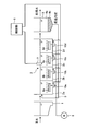
The present invention performs biological treatment of water to treat flowing within a plurality of aerobic tanks (2a-2d) configuring a reaction tank (2). Air is supplied to the reaction tank (2) from air diffusers (6a-6d) respectively provided to each of the aerobic tanks (2a-2d), aerating the water to treat. A nitrate meter (7) is provided at the inflow side of aerobic tank (2c), which is the desired position along the flow of water to treat in the reaction tank (2), and the nitrate concentration is measured. The nitrate meter (7) supplies the measured value of the nitrate concentration to a control unit (9). On the basis of the value of the nitrate concentration, in a manner so that the nitrate concentration falls within a predetermined range of controlled nitrate concentrations, the control unit (9) supplies a control signal to each gas supply amount control unit (10a-10d) to control the amount of supply of gas to the water to treat from the air diffusers (6a-6d) for each air diffuser (6a-6d) or in a batch manner for the air diffusers (6a-6d).
Description
本発明は、好気槽における曝気風量を制御する排水の処理装置、排水の処理方法、および排水の処理システム、並びに制御装置、制御方法、およびプログラムに関する。
The present invention relates to a waste water treatment apparatus that controls aeration air volume in an aerobic tank, a waste water treatment method, a waste water treatment system, a control device, a control method, and a program.
従来、生活排水または工場排水等の下水を処理する下水処理システムとして、標準活性汚泥法によるものや散水ろ床法によるものなど、様々な下水処理システムが実用化されている。
Heretofore, various sewage treatment systems, such as those based on the standard activated sludge method and those based on the water filter bed method, have been put to practical use as sewage treatment systems for treating sewage such as domestic drainage and factory drainage.
標準活性汚泥法による下水処理システムにおいては、反応槽内に処理対象の下水を流入させつつ、この反応槽内に存在する多種類の好気性微生物に対して酸素を供給する曝気処理を行う。これによって、反応槽内の下水中に含まれる有機物は、好気性微生物の作用によって分解され、安定した処理水質が得られる。
In a sewage treatment system based on the standard activated sludge method, aeration treatment is performed to supply oxygen to various types of aerobic microorganisms present in the reaction tank while allowing sewage to be treated to flow into the reaction tank. By this, the organic substance contained in the sewage in a reaction tank is decomposed | disassembled by the effect | action of an aerobic microbe, and the stable treated water quality is obtained.
反応槽内での曝気処理においては、曝気を行う散気装置に対して、流入水比例制御や、DO(溶存酸素)制御またはアンモニア制御(特許文献1参照)が行われる。流入水比例制御は、反応槽の流入側に設置された流量計を用いて、反応槽に流入する流入水量に比例した量の空気を散気装置に供給する制御である。DO制御は、反応槽の流出側の末端に設置した溶存酸素計(DO計)を用いて溶存酸素濃度を計測し、この溶存酸素濃度を所定の濃度に維持するように散気装置に空気を供給する制御である。アンモニア制御は、反応槽の流出側の末端に設置したアンモニア計を用いて、反応槽の末端におけるアンモニア性窒素(NH4-N)を所定の濃度に維持するように散気装置に空気を供給する制御である。
In the aeration process in the reaction tank, inflow water proportional control, DO (dissolved oxygen) control or ammonia control (see Patent Document 1) is performed on the aeration device that performs aeration. Inflow water proportional control is control which supplies air of the quantity proportional to the amount of inflowing water which flows into a reaction tank to a diffuser using the flowmeter installed in the inflow side of a reaction tank. The DO control measures the dissolved oxygen concentration using a dissolved oxygen meter (DO meter) installed at the end of the outflow side of the reaction tank, and air is supplied to the diffuser so as to maintain the dissolved oxygen concentration at a predetermined concentration. It is control to supply. Ammonia control supplies air to the diffuser so as to maintain ammonia nitrogen (NH 4 -N) at the end of the reaction vessel at a predetermined concentration using an ammonia meter installed at the end of the reaction vessel on the outflow side. Control.
しかしながら、上述した各種制御においては、次のような問題があった。すなわち、流入水比例制御においては、窒素を含有する流入水の有機物負荷やアンモニア負荷が変わって水質が変動するため、流入水量に比例させて空気量を制御すると、空気量の過不足が生じてしまう。また、DO制御においては、窒素を含有する流入水の有機物負荷やアンモニア負荷が変化し、これらの負荷が低下した時には空気量が過剰になりやすく、反対に、負荷が上昇した時には空気量が不足しやすくなる。さらに、アンモニア制御においては、窒素を含有する流入水のアンモニア負荷に応じて適切な量の空気を散気装置に供給できる反面、アンモニア制御を行う前段階での脱窒処理の制御を行うことが困難であった。
However, the various controls described above have the following problems. That is, in the inflow water proportional control, since the organic substance load and the ammonia load of the inflow water containing nitrogen are changed and the water quality fluctuates, if the air amount is controlled in proportion to the inflow water amount, the air amount will be excessive I will. Moreover, in DO control, the organic substance load and ammonia load of influent water containing nitrogen change, and when these loads decrease, the amount of air tends to be excessive, and conversely, the amount of air is insufficient when the load increases It becomes easy to do. Furthermore, in the ammonia control, while an appropriate amount of air can be supplied to the aeration device according to the ammonia load of the inflowing water containing nitrogen, the denitrification treatment may be performed in a stage before the ammonia control. It was difficult.
本発明は、上記に鑑みてなされたものであって、その目的は、曝気を行う反応槽に流入する窒素含有水の負荷に応じて気体供給量(曝気量)を適切に制御することによって、反応槽に適正量の酸素を供給することができるとともに、脱窒処理を適切に制御することができ、窒素除去率を向上させて処理水質を改善させることができる排水の処理装置、排水の処理方法、および排水の処理システム、並びに制御装置、制御方法、およびプログラムを提供することにある。
The present invention has been made in view of the above, and an object thereof is to appropriately control the gas supply amount (aeration amount) in accordance with the load of nitrogen-containing water flowing into a reaction tank performing aeration. An appropriate amount of oxygen can be supplied to the reaction tank, and denitrification treatment can be appropriately controlled, and the nitrogen removal rate can be improved to improve the treated water quality. A method, a waste water treatment system, and a control device, a control method, and a program.
上述した課題を解決し、上記目的を達成するために、本発明に係る排水の処理装置は、反応槽内において窒素含有水の流れに従って窒素含有水が含有するアンモニアが硝酸に硝化され、窒素含有水の流れ方向に沿った各位置で硝酸の各所望割合が脱窒されるように窒素含有水に対して流れ方向の略全域に亘って気体を供給する散気手段と、窒素含有水の流れ方向における所定位置に設けられ、所定位置で生じた硝酸の所望割合が脱窒されているか否かを確認する脱窒確認手段と、脱窒確認手段により確認された所定位置で硝化されて生じた硝酸の割合に応じて、硝酸の所望割合が脱窒されるように、窒素含有水の流れ方向に沿って脱窒確認手段より少なくとも上流側における散気手段による気体の供給量を制御する気体供給量制御手段と、を備えることを特徴とする。
In order to solve the problems described above and achieve the above object, in the waste water treatment apparatus according to the present invention, ammonia contained in nitrogen-containing water is nitrated to nitric acid according to the flow of nitrogen-containing water in a reaction tank, and nitrogen-containing A diffuser for supplying a gas over substantially the entire flow direction to the nitrogen-containing water so that each desired ratio of nitric acid is denitrified at each position along the water flow direction, the flow of the nitrogen-containing water Denitrification confirmation means provided at a predetermined position in the direction to confirm whether the desired proportion of nitric acid generated at the predetermined position is denitrified and nitrification occurred at the predetermined position confirmed by the denitrification confirmation means Gas supply that controls the amount of gas supplied by the aeration means at least upstream of the denitrification confirming means along the flow direction of the nitrogen-containing water so that the desired proportion of nitric acid is denitrified according to the proportion of nitric acid Quantity control means, Characterized in that it comprises.
本発明に係る排水の処理装置は、上記の発明において、散気手段が、時間の経過または窒素含有水の流れ方向に従って、硝化反応が行われる領域と脱窒反応が行われる領域とを、順次、交互、または繰り返し形成させるように気体を供給可能に構成されていることを特徴とする。
In the waste water treatment apparatus according to the present invention, in the above-mentioned invention, the aeration means sequentially carries out the region where the nitrification reaction is performed and the region where the denitrification reaction is performed according to the passage of time or the flow direction of the nitrogen-containing water. It is characterized in that the gas can be supplied so as to form alternately, or repeatedly.
本発明に係る排水の処理装置は、上記の発明において、気体供給量制御手段が、硝化反応により硝化されて生じた硝酸に対する所望割合の脱窒が脱窒確認手段によって確認できない場合に、窒素含有水の流れ方向に沿って脱窒確認手段より少なくとも上流側における散気手段による気体の供給量を増減制御することを特徴とする。
In the waste water treatment apparatus according to the present invention, in the above-mentioned invention, the gas supply control means may be configured to contain nitrogen if denitrification can not be confirmed by the denitrification confirmation means with respect to a desired ratio to nitric acid generated by nitrification reaction. It is characterized in that the amount of gas supplied by the aeration means at least on the upstream side of the denitrification confirming means is increased or decreased in the flow direction of the water.
本発明に係る排水の処理装置は、上記の発明において、脱窒確認手段が硝酸濃度を測定可能に構成された硝酸濃度測定手段であるとともに、硝酸の所望割合が脱窒されているか否かの確認を、硝酸濃度を測定することにより行い、気体供給量制御手段は、硝酸濃度測定手段によって測定された硝酸濃度が所定範囲内になるように、少なくとも窒素含有水の流れ方向に沿った硝酸濃度測定手段より上流側における散気手段からの気体の供給量を制御することを特徴とする。
In the waste water treatment apparatus according to the present invention, in the above-mentioned invention, the denitrification confirmation means is a nitric acid concentration measuring means configured to be capable of measuring a nitric acid concentration, and whether or not a desired ratio of nitric acid is denitrified The confirmation is carried out by measuring the nitric acid concentration, and the gas supply control means determines the nitric acid concentration along at least the flow direction of the nitrogen-containing water so that the nitric acid concentration measured by the nitric acid concentration measuring means is within the predetermined range. It is characterized in that the supply amount of gas from the aeration means on the upstream side of the measurement means is controlled.
本発明に係る排水の処理装置は、上記の発明において、脱窒確認手段がアンモニア性窒素を測定可能に構成されたアンモニア性窒素測定手段であるとともに、アンモニア性窒素の所望割合が脱窒されているか否かの確認を、アンモニア性窒素濃度を測定することにより行い、気体供給量制御手段は、アンモニア性窒素測定手段によって測定された硝酸濃度が所定範囲内になるように、少なくとも窒素含有水の流れ方向に沿ったアンモニア性窒素測定手段より上流側における散気手段からの気体の供給量を制御することを特徴とする。
In the waste water treatment apparatus according to the present invention, in the above invention, the denitrification confirmation means is an ammoniacal nitrogen measurement means configured to be capable of measuring ammoniacal nitrogen, and a desired ratio of the ammoniacal nitrogen is denitrified It is confirmed by measuring the ammoniacal nitrogen concentration whether or not there is at least nitrogen containing water so that the nitric acid concentration measured by the ammoniacal nitrogen measuring means falls within a predetermined range. It is characterized in that the amount of gas supplied from the aeration means on the upstream side of the ammonia nitrogen measuring means along the flow direction is controlled.
本発明に係る排水の処理装置は、上記の発明において、気体供給量制御手段は、窒素含有水の流れ方向に沿って脱窒確認手段より少なくとも上流側において、散気手段を、散気手段からの気体供給量が略一様になるように制御することを特徴とする。
In the waste water treatment apparatus according to the present invention, in the above-mentioned invention, the gas supply control means comprises a diffuser in at least the upstream side of the denitrification check in the flow direction of the nitrogen-containing water and the diffuser. It controls so that the gas supply amount of the gas becomes substantially uniform.
本発明に係る排水の処理装置は、気体供給量制御手段は、窒素含有水の流れ方向に沿った全域において、散気手段を、散気手段からの気体の供給量が略一様になるように制御することを特徴とする。
In the waste water treatment apparatus according to the present invention, the gas supply amount control means is configured such that the supply of gas from the diffusion means is substantially uniform throughout the entire area along the flow direction of the nitrogen-containing water. To control.
本発明に係る排水の処理装置は、上記の発明において、反応槽の前段に嫌気槽が設けられていることを特徴とする。
The waste water treatment apparatus according to the present invention is characterized in that, in the above invention, an anaerobic tank is provided at a front stage of the reaction tank.
本発明に係る排水の処理方法は、反応槽内を流れる窒素含有水に対して硝化反応および脱窒反応による生物処理を行う生物処理ステップと、窒素含有水の流れに従って窒素含有水に含まれるアンモニアが硝酸に硝化され、窒素含有水の流れ方向に沿った各位置で硝酸の各所望割合が脱窒されるように窒素含有水に対して流れ方向の略全域に亘って気体を供給する散気ステップと、窒素含有水の流れ方向における所定位置で生じた硝酸の所望割合が脱窒されているか否かを確認する脱窒確認ステップと、脱窒確認ステップにおいて確認された所定位置で硝化されて生じた硝酸の割合に応じて、硝酸の所望割合が脱窒されるように、窒素含有水の流れ方向に沿った所定位置より少なくとも上流側における気体の供給量を制御する気体供給量制御ステップと、を含むことを特徴とする。
The method for treating waste water according to the present invention comprises a biological treatment step of performing biological treatment by nitrification reaction and denitrification reaction on nitrogen-containing water flowing in a reaction tank, ammonia contained in nitrogen-containing water according to the flow of nitrogen-containing water Is diffused into nitric acid, and the diffused gas is supplied to the nitrogen-containing water over substantially the entire flow direction so that each desired ratio of nitric acid is denitrified at each position along the flow direction of the nitrogen-containing water Step, a denitrification confirmation step of confirming whether a desired ratio of nitric acid generated at a predetermined position in the flow direction of nitrogen-containing water is denitrified, and nitrification at the predetermined position confirmed in the denitrification confirmation step The gas supply amount control for controlling the gas supply amount at least on the upstream side of the predetermined position along the flow direction of the nitrogen-containing water so that the desired proportion of nitric acid is denitrified according to the proportion of nitric acid generated Characterized in that it comprises a step, a.
本発明に係る排水の処理方法は、上記の発明において、時間の経過または窒素含有水の流れ方向に従って、硝化反応が行われる領域と脱窒反応が行われる領域とを、順次、交互、または繰り返し形成させるように窒素含有水に気体を供給することを特徴とする。
In the method for treating waste water according to the present invention, in the above-mentioned invention, the area in which the nitrification reaction is performed and the area in which the denitrification reaction is sequentially alternated or repeated according to the passage of time or the flow direction of the nitrogen-containing water. A gas is supplied to the nitrogen-containing water to be formed.
本発明に係る排水の処理方法は、上記の発明において、脱窒確認ステップにおいて確認される硝酸の割合が所定位置における硝酸濃度であり、気体供給量制御ステップにおいて、脱窒確認ステップで測定された硝酸濃度が所定範囲に収まる方向に、所定位置より窒素含有水の流れ方向に沿った少なくとも上流側における気体の供給量を制御することを特徴とする。
In the method for treating wastewater according to the present invention, in the above invention, the ratio of nitric acid confirmed in the denitrification confirmation step is the nitric acid concentration at the predetermined position, and is measured in the denitrification confirmation step in the gas supply control step. It is characterized in that the supply amount of gas at least on the upstream side along the flow direction of the nitrogen-containing water from the predetermined position is controlled in the direction in which the nitric acid concentration falls within the predetermined range.
本発明に係る排水の処理システムは、窒素含有水の流れ方向における所定位置に設けられるとともに、流れ方向に従ってアンモニアが硝酸に硝化され、流れ方向に沿った各位置で硝酸の各所望割合が脱窒されるように流れ方向の略全域に亘って気体が供給される窒素含有水に対して、所定位置で生じた硝酸の所望割合が脱窒されているか否かを確認する脱窒確認手段と、脱窒確認手段により確認された所定位置で硝化されて生じた硝酸の割合に応じて、硝酸の所望割合が脱窒されるように、窒素含有水の流れ方向に沿った脱窒確認手段より少なくとも上流側における窒素含有水に供給する気体の供給量を制御する気体供給量制御手段と、を備えることを特徴とする。
The waste water treatment system according to the present invention is provided at a predetermined position in the flow direction of nitrogen-containing water, and ammonia is nitrated to nitric acid according to the flow direction, and each desired ratio of nitric acid is denitrified at each position along the flow direction. Denitrification confirmation means for confirming whether or not a desired ratio of nitric acid generated at a predetermined position is denitrified with respect to nitrogen-containing water to which gas is supplied over substantially the entire flow direction, as described above; At least from the denitrification confirming means along the flow direction of the nitrogen-containing water so that the desired proportion of nitric acid is denitrified according to the proportion of nitric acid generated by nitrification at the predetermined position confirmed by the denitrification confirming means And gas supply amount control means for controlling the supply amount of gas supplied to the nitrogen-containing water on the upstream side.
本発明に係る制御装置は、窒素含有水の流れに従って窒素含有水に含まれるアンモニアが硝酸に硝化され、窒素含有水の流れ方向に沿った各位置で硝酸の各所望割合が脱窒されるように窒素含有水に流れ方向の略全域に亘って気体を供給する散気手段に対して、窒素含有水の流れ方向における所定位置で生じた硝酸の所望割合が脱窒されているか否かを確認する脱窒確認手段が確認した所定位置で硝化されて生じた硝酸の割合に応じて、硝酸の所望割合が脱窒されるように窒素含有水の流れ方向に沿った脱窒確認手段より少なくとも上流側における気体の供給量を制御することを特徴とする。
In the control device according to the present invention, ammonia contained in nitrogen-containing water is nitrified to nitric acid according to the flow of nitrogen-containing water, and each desired ratio of nitric acid is denitrified at each position along the flow direction of nitrogen-containing water Check whether the desired proportion of nitric acid generated at a predetermined position in the flow direction of nitrogen-containing water is denitrified with respect to the diffusion means for supplying the gas to substantially all of the flow direction in the nitrogen-containing water At least upstream of the denitrification confirmation means along the flow direction of the nitrogen-containing water so that the desired proportion of nitric acid is denitrified according to the proportion of nitric acid generated by nitrification at the predetermined position confirmed by the denitrification confirmation means It is characterized in that the amount of gas supplied on the side is controlled.
本発明に係る制御方法は、窒素含有水に対する気体供給量を制御する制御装置による制御方法において、窒素含有水の流れ方向における所定位置において、流れ方向に従ってアンモニアが硝酸に硝化され、流れ方向に沿った各位置で硝酸の各所望割合が脱窒されるように流れ方向の略全域に亘って気体が供給される窒素含有水に対して、脱窒確認手段により所定位置で生じた硝酸の所望割合が脱窒されているか否かを確認する脱窒確認ステップと、脱窒確認ステップにおいて確認された所定位置で硝化されて生じた硝酸の割合に応じて、硝酸の所望割合が脱窒されるように、窒素含有水の流れ方向に沿った所定位置より少なくとも上流側における窒素含有水に供給する気体の供給量を制御する気体供給量制御ステップと、を含むことを特徴とする。
The control method according to the present invention is a control method using a control device that controls the amount of gas supplied to nitrogen-containing water, wherein ammonia is nitrated to nitric acid according to the flow direction at a predetermined position in the flow direction of nitrogen-containing water Desired ratio of nitric acid generated at a predetermined position by the denitrification confirmation means to nitrogen-containing water to which gas is supplied substantially throughout the flow direction so that each desired ratio of nitric acid is denitrified at each position The desired proportion of nitric acid is denitrified according to the proportion of nitric acid produced by nitrification at the predetermined position confirmed in the denitrification confirmation step of confirming whether or not the denitrification is performed and in the denitrification confirmation step And d) controlling the amount of gas supplied to the nitrogen-containing water at least upstream of the predetermined position along the flow direction of the nitrogen-containing water. To.
本発明に係るプログラムは、窒素含有水の流れ方向における所定位置で、流れ方向に従ってアンモニアが硝酸に硝化され、流れ方向に沿った各位置で硝酸の各所望割合が脱窒されるように流れ方向の略全域に亘って気体が供給される窒素含有水に対して、所定位置で生じた硝酸の所望割合が脱窒されているか否かを確認する脱窒確認ステップと、脱窒確認ステップにおいて確認された所定位置で硝化されて生じた硝酸の割合に応じて、硝酸の所望割合が脱窒されるように、窒素含有水の流れ方向に沿った所定位置より少なくとも上流側における窒素含有水に供給する気体の供給量を制御する気体供給量制御ステップと、をコンピュータに実行させることを特徴とする。
In the program according to the present invention, the flow direction is such that ammonia is nitrated to nitric acid according to the flow direction at a predetermined position in the flow direction of nitrogen-containing water, and each desired ratio of nitric acid is denitrified at each position along the flow direction. In the denitrification confirmation step of confirming whether or not the desired ratio of the nitric acid generated at the predetermined position is denitrified with respect to the nitrogen-containing water to which the gas is supplied substantially over the entire area of Supply the nitrogen-containing water at least upstream of the predetermined position along the flow direction of the nitrogen-containing water so that the desired proportion of nitric acid is denitrified according to the proportion of nitric acid generated at the predetermined position. And a control step of controlling a supply amount of gas to be performed by the computer.
本発明に係る排水の処理装置、排水の処理方法、および排水の処理システム、並びに制御装置、制御方法、およびプログラムによれば、曝気を行う反応槽に流入する窒素含有水の負荷に応じて気体供給量を適切に制御することができ、反応槽に適正量の酸素を供給することができるとともに、脱窒処理を適切に制御することができ、窒素除去率を向上させて処理水質を改善させることが可能となる。
According to the waste water treatment apparatus, waste water treatment method, waste water treatment system, control apparatus, control method, and program according to the present invention, the gas according to the load of nitrogen-containing water flowing into the aeration reaction tank The amount of supply can be properly controlled, the appropriate amount of oxygen can be supplied to the reaction tank, the denitrification treatment can be appropriately controlled, and the nitrogen removal rate is improved to improve the treated water quality It becomes possible.
以下、本発明の実施形態について図面を参照しつつ説明する。なお、以下の実施形態の全図においては、同一または対応する部分には同一の符号を付す。また、本発明は以下に説明する実施形態によって限定されるものではない。
Hereinafter, embodiments of the present invention will be described with reference to the drawings. In all the drawings of the following embodiments, the same or corresponding parts are denoted by the same reference numerals. Further, the present invention is not limited by the embodiments described below.
(第1の実施形態)
(排水処理装置の構成)
まず、本発明の第1の実施形態による制御装置を含む排水の処理装置の構成について説明する。図1は、本発明の第1の実施形態である排水処理装置の構成を示す模式図である。図1に示すように、本発明の第1の実施形態である排水処理装置は、最初沈殿池1、順次連通した複数段の好気槽2a,2b,2c,2d(第1槽~第4槽)からなる反応槽2、固液分離槽3、汚泥返送経路5、および制御部9を備える。 First Embodiment
(Configuration of wastewater treatment system)
First, the configuration of a waste water treatment apparatus including a control device according to a first embodiment of the present invention will be described. FIG. 1 is a schematic view showing the configuration of a waste water treatment apparatus according to a first embodiment of the present invention. As shown in FIG. 1, the waste water treatment apparatus according to the first embodiment of the present invention comprises afirst settling tank 1, a plurality of stages of aerobic tanks 2 a, 2 b, 2 c and 2 d (first tank to fourth And a solid-liquid separation tank 3, a sludge return path 5, and a control unit 9.
(排水処理装置の構成)
まず、本発明の第1の実施形態による制御装置を含む排水の処理装置の構成について説明する。図1は、本発明の第1の実施形態である排水処理装置の構成を示す模式図である。図1に示すように、本発明の第1の実施形態である排水処理装置は、最初沈殿池1、順次連通した複数段の好気槽2a,2b,2c,2d(第1槽~第4槽)からなる反応槽2、固液分離槽3、汚泥返送経路5、および制御部9を備える。 First Embodiment
(Configuration of wastewater treatment system)
First, the configuration of a waste water treatment apparatus including a control device according to a first embodiment of the present invention will be described. FIG. 1 is a schematic view showing the configuration of a waste water treatment apparatus according to a first embodiment of the present invention. As shown in FIG. 1, the waste water treatment apparatus according to the first embodiment of the present invention comprises a
最初沈殿池1には、窒素含有原水(以下、原水)が流入する。最初沈殿池1においては、原水を緩やかに流水させて、比較的粒子の小さいゴミなどを沈殿させる。
Nitrogen-containing raw water (hereinafter, raw water) flows into the first sedimentation tank 1. In the first settling tank 1, the raw water is allowed to flow gently to precipitate relatively small particles of dust and the like.
反応槽2には、最初沈殿池1から流出した窒素含有水である被処理水が流入する。この反応槽2を構成する複数段の好気槽2a~2dは、被処理水の流れ方向に沿って配列されている。ここで、反応槽2における被処理水の流入側においては、BOD酸化領域が生じている場合もある。そして、好気槽2a~2dはそれぞれ、散気手段としての散気部6a,6b,6c,6dを備える。散気部6a~6dは、ブロア8が供給する空気などの気体を用いて、それぞれの好気槽2a~2d内に散気を行い、貯留されている活性汚泥を曝気する。それぞれの好気槽2a~2dにおいては、主に、好気条件下で被処理水中に含まれるアンモニア性窒素が亜硝酸性窒素および硝酸性窒素に硝化される。それぞれの散気部6a~6dが設けられた好気槽2a~2dは、直線的に配列しても良く、反応槽2の一例を示す平面図である図2Aに示すように、途中で折り返して配列した迂回水路としても良い。
Water to be treated, which is nitrogen-containing water that first flowed out of the sedimentation tank 1, flows into the reaction tank 2. A plurality of stages of aerobic tanks 2a to 2d constituting the reaction tank 2 are arranged along the flow direction of the water to be treated. Here, on the inflow side of the water to be treated in the reaction tank 2, there may be a case where a BOD oxidation region is generated. The aerobic tanks 2a to 2d are provided with aeration units 6a, 6b, 6c and 6d as aeration means, respectively. The aeration units 6a to 6d perform aeration in the respective aerobic tanks 2a to 2d using a gas such as air supplied by the blower 8 to aerate the activated sludge stored. In each of the aerobic tanks 2a to 2d, ammonia nitrogen contained in the water to be treated is mainly nitrified to nitrite nitrogen and nitrate nitrogen under aerobic conditions. The aerobic tanks 2a to 2d provided with the respective aeration units 6a to 6d may be linearly arranged, and as shown in FIG. 2A which is a plan view showing an example of the reaction tank 2, they are folded halfway It is good also as a detour channel arranged.
また、図1に示すように、散気部6a~6dにはそれぞれ、制御装置を構成する気体供給量制御手段の一部としての気体供給量制御部10a,10b,10c,10dが設けられている。気体供給量制御部10a~10dはそれぞれ、空気流量制御弁などから構成され、制御装置を構成する気体供給量制御手段の一部としての制御部9からの制御信号に従って、それぞれの好気槽2a~2dにおける散気部6a~6dからの気体供給量をそれぞれ一様または個別に制御する。
Further, as shown in FIG. 1, the aeration units 6a to 6d are respectively provided with gas supply amount control units 10a, 10b, 10c and 10d as a part of the gas supply amount control means constituting the control device. There is. Each of the gas supply amount control units 10a to 10d includes an air flow rate control valve or the like, and each aerobic tank 2a according to a control signal from the control unit 9 as a part of the gas supply amount control means constituting the control device. The amount of gas supplied from the aeration unit 6a to 6d at 2d to 2d is controlled uniformly or individually.
制御装置としての制御部9は、例えばCPU、ROMやRAMなどの記憶媒体、およびハードディスクなどの記録媒体を有して構成されるコンピュータ(PC)などからなる。制御部9においては、記録媒体に後述する排水の処理方法や制御方法を実行可能な所定のプログラムが格納されている。制御部9は、後述するように、入力された硝酸濃度の計測値データなどの確認信号に応答して、格納されたプログラムに従って制御信号を出力することで、気体供給量制御部10a~10dを制御して散気部6a~6dからの気体供給量を制御する。
The control unit 9 as a control device includes, for example, a computer (PC) configured to have a recording medium such as a CPU, a storage medium such as a ROM or a RAM, and a hard disk. In the control unit 9, the recording medium stores a predetermined program capable of executing a method of treating and controlling drainage described later. As described later, the control unit 9 outputs the control signal according to the stored program in response to the confirmation signal such as the measured value data of the nitric acid concentration input, thereby controlling the gas supply amount control units 10a to 10d. Control is performed to control the amount of gas supplied from the aeration units 6a to 6d.
また、反応槽2における被処理水の流れに沿った所望の位置には、硝酸計7が備えられている。この脱窒確認手段としての硝酸計7は、脱窒を制御する所望の位置における被処理水の硝酸濃度を測定する硝酸濃度測定手段である。この第1の実施形態において、硝酸計7は、例えば反応槽2のほぼ中間位置である好気槽2cの流入位置に設置する。ここで、硝酸計7の設置位置としては、所望の位置に設定可能であり、後述するように脱窒反応の制御に用いることから、脱窒反応により除去したい窒素量を確保できる位置より下流側、かつ、反応槽2の内部において硝化反応を十分に行うことができる位置より上流側が望ましい。さらには、硝酸計7の設置位置は、あらかじめ測定した全窒素濃度、硝酸性窒素、亜硝酸性窒素、およびアンモニア性窒素のそれぞれの濃度に関する反応槽2の位置依存性に基づいて決定可能である。そして、制御部9、気体供給量制御部10、および硝酸計7によって、排水の処理システムが構成されている。
A nitric acid meter 7 is provided at a desired position along the flow of the water to be treated in the reaction tank 2. The nitric acid meter 7 as the denitrification confirming means is a nitric acid concentration measuring means for measuring the nitric acid concentration of the water to be treated at a desired position for controlling the denitrification. In the first embodiment, the nitric acid meter 7 is installed, for example, at the inflow position of the aerobic tank 2 c which is approximately the middle position of the reaction tank 2. Here, the installation position of the nitric acid meter 7 can be set to a desired position, and is used for control of the denitrification reaction as described later, so it is downstream from the position where the amount of nitrogen to be removed by the denitrification reaction can be secured. And, it is desirable that the upstream side of the position where the nitrification reaction can be sufficiently performed inside the reaction tank 2. Furthermore, the installation position of the nitric acid meter 7 can be determined based on the position dependency of the reaction vessel 2 with respect to each concentration of total nitrogen concentration, nitrate nitrogen, nitrite nitrogen, and ammonia nitrogen which are measured in advance. . The control unit 9, the gas supply control unit 10, and the nitric acid meter 7 constitute a waste water treatment system.
なお、本明細書において硝酸とは、硝酸(HNO3)、亜硝酸(HNO2)、硝酸性窒素(NO3-N)、亜硝酸性窒素(NO2-N)、硝酸性窒素と亜硝酸性窒素との集合、および硝酸と亜硝酸とをともに示すNOxを含む概念である。また、本明細書においてアンモニアとは、アンモニアおよびアンモニア性窒素を含む概念である。すなわち、本明細書において硝酸濃度は、硝酸、亜硝酸、硝酸性窒素、亜硝酸性窒素、硝酸性窒素と亜硝酸性窒素との集合、および硝酸と亜硝酸とをともに示すNOxの、いずれの濃度であってもよく、アンモニア濃度は、アンモニア(NH3)およびアンモニア性窒素(NH4-N)のいずれの濃度であっても良い。
In the present specification, nitric acid refers to nitric acid (HNO 3 ), nitrous acid (HNO 2 ), nitrate nitrogen (NO 3 -N), nitrite nitrogen (NO 2 -N), nitrate nitrogen and nitrite collection of the sexual nitrogen, and is a concept including NO x indicating both nitrate and nitrite. Moreover, in the present specification, ammonia is a concept including ammonia and ammonia nitrogen. That is, in the present specification, the concentration of nitric acid is any of nitric acid, nitrous acid, nitrate nitrogen, nitrite nitrogen, aggregation of nitrate nitrogen and nitrite nitrogen, and NO x both of nitrate and nitrite. The ammonia concentration may be any concentration of ammonia (NH 3 ) and ammoniacal nitrogen (NH 4 -N).
また、反応槽2を構成する複数段の好気槽2a~2dが図2Aに示すように折り返して配列されている場合においても、硝酸計7は反応槽2の被処理水の流れに沿った所望の位置、例えば好気槽2cの流入位置などに設けられる。なお、硝酸計7の設置位置に関する詳細については後述する。
Further, even when the plurality of stages of aerobic tanks 2a to 2d constituting the reaction tank 2 are arranged in a folded manner as shown in FIG. 2A, the nitric acid meter 7 follows the flow of the water to be treated in the reaction tank 2. It is provided at a desired position, for example, the inflow position of the aerobic tank 2c. In addition, the detail regarding the installation position of nitric acid meter 7 is mentioned later.
そして、図1に示すように、硝酸計7は、測定した硝酸濃度の値を制御部9に供給する。測定された硝酸濃度の値が供給された制御部9は、気体供給量制御部10a~10dに制御信号を供給し、硝酸濃度の値に基づいて、散気部6a~6dによる気体供給量を制御する。すなわち、制御部9および気体供給量制御部10a~10dによって、制御装置である気体供給量制御手段が構成される。なお、硝酸計7の設置位置および制御部9による制御の詳細については後述する。
Then, as shown in FIG. 1, the nitric acid meter 7 supplies the measured value of the nitric acid concentration to the control unit 9. The control unit 9 to which the measured value of nitric acid concentration is supplied supplies a control signal to the gas supply amount control units 10a to 10d, and based on the nitric acid concentration value, the gas supply amount by the aeration unit 6a to 6d is Control. That is, the control unit 9 and the gas supply control units 10a to 10d constitute a gas supply control unit which is a control device. The installation position of the nitric acid meter 7 and the control by the control unit 9 will be described later in detail.
固液分離槽3には、最下流の好気槽2dから流出した被処理水が流入する。固液分離槽3においては、被処理水が分離液4aと活性汚泥4bとに分離する。固液分離槽3の側壁には、配管(図示せず)が接続されており、この配管を介して分離液4aが消毒処理過程に送られるように構成されている。また、固液分離槽3の底部には、汚泥返送経路5が接続されており、固液分離槽3の底部に堆積した活性汚泥4bを好気槽2aに返送できるように構成されている。これにより、好気槽2aおよび下流側の好気槽2b,2c,2d内の生物量を所定量に維持することができる。
The water to be treated that has flowed out of the most downstream aerobic tank 2 d flows into the solid-liquid separation tank 3. In the solid-liquid separation tank 3, the water to be treated is separated into the separated liquid 4a and the activated sludge 4b. A pipe (not shown) is connected to the side wall of the solid-liquid separation tank 3, and the separation liquid 4a is sent to the disinfection process through this pipe. A sludge return path 5 is connected to the bottom of the solid-liquid separation tank 3 so that the activated sludge 4b deposited on the bottom of the solid-liquid separation tank 3 can be returned to the aerobic tank 2a. Thereby, the amount of biomass in the aerobic tank 2a and the downstream aerobic tanks 2b, 2c, 2d can be maintained at a predetermined amount.
(排水の処理方法における気体供給量制御)
次に、好気槽2a~2dにおいて行われる排水の処理方法、およびこれに伴う制御方法並びに制御部9が実行するプログラムによる気体供給量制御について説明する。図4は、この第1の実施形態による処理方法を示すフローチャートである。 (Gas supply control in wastewater treatment method)
Next, a method of treating waste water performed in theaerobic tanks 2a to 2d, a control method associated therewith, and control of gas supply amount by a program executed by the control unit 9 will be described. FIG. 4 is a flowchart showing the processing method according to the first embodiment.
次に、好気槽2a~2dにおいて行われる排水の処理方法、およびこれに伴う制御方法並びに制御部9が実行するプログラムによる気体供給量制御について説明する。図4は、この第1の実施形態による処理方法を示すフローチャートである。 (Gas supply control in wastewater treatment method)
Next, a method of treating waste water performed in the
この好気槽2a~2dにおいて行われる排水の処理方法においては、まず、図1に示す最初沈殿池1からの被処理水が、好気槽2aから好気槽2dに順次送られる。それぞれの好気槽2a~2dにおいては、好気性条件下で活性汚泥中の好気性微生物である硝化菌により、被処理水中のアンモニア性窒素(NH4-N)が、下記の反応式(1)~(3)のように、亜硝酸性窒素(NO2-N)や硝酸性窒素(NO3-N)に硝化される(図4中、ステップST1およびステップST2)。
In the method of treating waste water performed in the aerobic tanks 2a to 2d, first, the water to be treated from the first sedimentation tank 1 shown in FIG. 1 is sequentially sent from the aerobic tank 2a to the aerobic tank 2d. In each of the aerobic tanks 2a to 2d, ammonia nitrogen (NH 4 -N) in the water to be treated is converted by the following reaction formula (1) by nitrifying bacteria which are aerobic microorganisms in activated sludge under aerobic conditions. As shown in (4) to (3), nitrification is carried out to nitrite nitrogen (NO 2 -N) or nitrate nitrogen (NO 3 -N) (in FIG. 4, step ST1 and step ST2).
NH3+O2+2e-+2H+→NH2OH+H2O …(1)
NH2OH+H2O→NO2 -+5H++4e- …(2)
NO2 -+0.5O2→NO3 - …(3) NH 3 + O 2 + 2e − + 2H + → NH 2 OH + H 2 O (1)
NH 2 OH + H 2 O → NO 2 − + 5H + + 4e − ... (2)
NO 2 - + 0.5O 2 → NO 3 - ... (3)
NH2OH+H2O→NO2 -+5H++4e- …(2)
NO2 -+0.5O2→NO3 - …(3) NH 3 + O 2 + 2e − + 2H + → NH 2 OH + H 2 O (1)
NH 2 OH + H 2 O → NO 2 − + 5H + + 4e − ... (2)
NO 2 - + 0.5O 2 → NO 3 - ... (3)
一方、反応槽2における被処理水中の酸素量が少ない領域や場合によって硝化槽などにおいても、酸素量が少ない領域において脱窒菌による脱窒反応(嫌気反応)が発生する。そのため、この脱窒反応を生じる領域(脱窒反応領域)に充分な炭素源を供給すれば、脱窒反応も充分に進行させることができる。その結果、反応槽2において、部分的に脱窒反応が行われる領域が発生する。これにより、下記の反応式(4)~(10)のように、硝化が不充分であることによって発生した亜酸化窒素(N2O)ガスを分解したり、亜酸化窒素を発生させることなく亜硝酸を還元したりして、窒素と二酸化炭素とに分解させて、窒素除去を行うことができる。
On the other hand, denitrification reaction (anaerobic reaction) by denitrifying bacteria occurs in the region where the amount of oxygen is small or in a region where the amount of oxygen in the water to be treated in the reaction tank 2 is small or in some cases the nitrification tank. Therefore, if a sufficient carbon source is supplied to the region (the denitrification reaction region) in which the denitrification reaction occurs, the denitrification reaction can be sufficiently advanced. As a result, in the reaction tank 2, a region where the denitrification reaction is partially generated is generated. As a result, as shown in the following reaction formulas (4) to (10), nitrous oxide (N 2 O) gas generated due to insufficient nitrification is not decomposed or nitrous oxide is not generated. Nitrite can be reduced and decomposed to nitrogen and carbon dioxide to effect nitrogen removal.
NO2
-+3H++2e- → 0.5N2O+1.5H2O …(4)
NO2 -+H++2(H) → 0.5N2O+1.5H2O …(5)
NO3 -+H++5(H) → 0.5N2+3H2O …(6)
NO3 -+2H → NO2 -+H2O …(7)
NO2 -+H++(H) → NO+H2O …(8)
NO+(H) → 0.5N2O+0.5H2O …(9)
N2O+2(H) → N2+H2O …(10) NO 2 - + 3H + + 2e - → 0.5N 2 O + 1.5H 2 O ... (4)
NO 2 − + H + +2 (H) → 0.5 N 2 O + 1.5 H 2 O (5)
NO 3 − + H + +5 (H) → 0.5 N 2 + 3 H 2 O (6)
NO 3 − + 2H → NO 2 − + H 2 O (7)
NO 2 - + H + + ( H) → NO + H 2 O ... (8)
NO + (H) → 0.5 N 2 O + 0.5 H 2 O (9)
N 2 O + 2 (H) → N 2 + H 2 O (10)
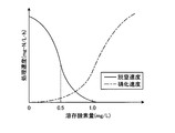
ここで、本発明者は、このような脱窒反応と硝化反応とが並行して進行する場合について、反応槽2における好気槽2aの流入側から好気槽2dの流出側の方向、すなわち被処理水の流れの方向に沿って、複数の位置での、アンモニア性窒素(NH4-N)、亜硝酸性窒素(NO2-N)、および硝酸性窒素(NO3-N)におけるそれぞれの窒素濃度と、これらを合計した全窒素濃度とを測定した。図3は、NH4-N、NO2-N、およびNO3-Nの窒素濃度および全窒素濃度を、反応槽2の位置によって測定した結果を示すグラフである。
Here, in the case where the denitrification reaction and the nitrification reaction proceed in parallel, the inventor of the present invention is directed from the inflow side of the aerobic tank 2a in the reaction tank 2 to the outflow side of the aerobic tank 2d, ie, Each of ammonia nitrogen (NH 4 -N), nitrite nitrogen (NO 2 -N), and nitrate nitrogen (NO 3 -N) at a plurality of positions along the flow direction of the water to be treated And the total nitrogen concentration obtained by summing them. FIG. 3 is a graph showing the results of measuring the nitrogen concentration and the total nitrogen concentration of NH 4 -N, NO 2 -N, and NO 3 -N according to the position of the reaction tank 2.
図3に示すように、反応槽2の比較的前半側である好気槽2aの流入側から好気槽2bの流出側の位置までは、被処理水の流れに従って、NO2-NおよびNO3-Nの窒素濃度があまり増加せず、全窒素濃度が減少する。これは、反応槽2の上流側の好気槽2a,2bにおいて、硝化反応領域と脱窒反応領域とが存在し、硝化反応領域における硝化処理と脱窒反応領域における脱窒処理とが同時に進行して、窒素除去率が向上しているためと考えられる。また、反応槽2における比較的後半側である好気槽2cの流入側から好気槽2dの流出側の位置までは、NO2-NおよびNO3-Nの窒素濃度が増加している。すなわち、本発明者は、反応槽2の下流側の好気槽2c,2dにおいては、脱窒反応が継続して進行しているとともに、硝化反応が急速に進行していると考えた。そこで、本発明者は、まず、硝酸計7を反応槽2における窒素濃度が減少する所望の位置に設置して、この位置における硝酸濃度に基づいて、硝酸計7より少なくとも上流側における気体の供給量を略一様または個別に制御すれば、硝酸計7より上流側で発生している脱窒反応および硝化反応をともに制御可能になることを想起した。
As shown in FIG. 3, from the inflow side of the aerobic tank 2a on the relatively front half side of the reaction tank 2 to the position on the outflow side of the aerobic tank 2b, NO 2 -N and NO according to the flow of the water to be treated The 3 -N nitrogen concentration does not increase much and the total nitrogen concentration decreases. This is because there are a nitrification reaction zone and a denitrification reaction zone in the aerobic tanks 2a and 2b on the upstream side of the reaction vessel 2, and the nitrification treatment in the nitrification reaction zone and the denitrification treatment in the denitrification reaction zone proceed simultaneously It is considered that the nitrogen removal rate is improved. The nitrogen concentrations of NO 2 -N and NO 3 -N increase from the inflow side of the aerobic tank 2c, which is the second half of the reaction tank 2, to the position of the outflow side of the aerobic tank 2d. That is, in the aerobic tank 2c, 2d of the downstream side of the reaction tank 2, this inventor considered that the denitrification reaction was advancing continuously and the nitrification reaction was advancing rapidly. Therefore, the inventor first places the nitric acid meter 7 at a desired position where the nitrogen concentration in the reaction tank 2 decreases, and supplies gas at least upstream of the nitric acid meter 7 based on the nitric acid concentration at this position. It was recalled that if the amount is controlled approximately uniformly or individually, both denitrification reaction and nitrification reaction occurring upstream of the nitric acid meter 7 can be controlled.
具体的に本発明者は、被処理水が反応槽2内を流下するに従って、散気部6a~6dによって被処理水に含まれるアンモニア(NH4)が徐々に硝酸(亜硝酸性窒素(NO2-N)および硝酸性窒素(NO3-N))に硝化されるように、反応槽2内における被処理水に対して、その流れ方向の略全体に亘って気体を供給することによって、反応槽2内における被処理水の流れ方向における各位置で硝化されて生じた硝酸の各所望割合が脱窒できることを知見した。これにより、本発明者は、硝酸計7を所望位置に設置して、硝酸計7により計測される計測値が所定範囲に収まるように、少なくとも硝酸計7より上流側の散気部6からの気体供給量を一様または個別に制御することによって、硝酸計7より上流側の脱窒反応および硝化反応を制御できることを知見した。
Specifically, as the water to be treated flows down the reaction tank 2, ammonia (NH 4 ) contained in the water to be treated is gradually added to the nitric acid (NO nitrogen (NO) by the aeration parts 6 a to 6 d. By supplying a gas to the water to be treated in the reaction vessel 2 substantially throughout the flow direction so as to be nitrified to 2- N) and nitrate nitrogen (NO 3 -N)), It has been found that each desired ratio of nitric acid produced by nitrification at each position in the flow direction of the water to be treated in the reaction tank 2 can be denitrified. As a result, the inventor places the nitric acid meter 7 at a desired position, and at least from the aeration unit 6 on the upstream side of the nitric acid meter 7 so that the measurement value measured by the nitric acid meter 7 falls within the predetermined range. It has been found that the denitrification reaction and the nitrification reaction upstream of the nitric acid meter 7 can be controlled by uniformly or separately controlling the gas supply amount.
そこで、本発明においては、まず、制御部9は、好気槽2cの流入側に設置した硝酸計7による硝酸濃度の測定をモニタリングするとともに、被処理水の流れ方向に沿って少なくとも硝酸計7より上流側の気体供給量制御部10a,10bを制御する。そして、本発明においてはさらに、気体供給量制御部10a~10dによって反応槽2における気体供給量、すなわちそれぞれの好気槽2a~2dの気体供給量を調整する。この場合、反応槽2における脱窒反応を制御することを考慮すると、硝酸計7は、脱窒反応および硝化反応が共存する領域のうちの脱窒反応の制御を所望する位置、例えば、硝化反応による硝酸の発生を抑制しつつ脱窒反応を進行させる必要のある反応槽2における領域の最下流側の近傍に設置することが望ましい。
Therefore, in the present invention, first, the control unit 9 monitors the measurement of the nitric acid concentration by the nitric acid meter 7 installed on the inflow side of the aerobic tank 2c, and at least the nitric acid meter 7 along the flow direction of the water to be treated. The gas supply amount control units 10a and 10b on the upstream side are controlled. Further, in the present invention, the gas supply amount in the reaction tank 2, that is, the gas supply amount in each of the aerobic tanks 2a to 2d is adjusted by the gas supply amount control units 10a to 10d. In this case, in consideration of controlling the denitrification reaction in the reaction tank 2, the nitric acid meter 7 is a position where it is desired to control the denitrification reaction in the region where the denitrification reaction and the nitrification reaction coexist, for example, the nitrification reaction It is desirable to install in the vicinity of the most downstream side of the field in reaction tank 2 which needs to advance denitrification reaction, controlling generation of nitric acid by this.
そこで、この第1の実施形態においては、硝酸計7を好気槽2cの流入側に設置するのが望ましい。そして、この硝酸計7によって測定されるNO2-NおよびNO3-Nの合計の硝酸濃度があらかじめ設定した目標範囲になるように、制御部9が、被処理水の流れ方向に沿って硝酸計7より上流側の少なくとも気体供給量制御部10a,10bを制御する。なお、必要に応じて制御部9は、気体供給量制御部10c,10dに制御信号を供給する。これにより、制御部9は、それぞれの好気槽2a,2b、さらには好気槽2c,2dにおける気体供給量をそれぞれ個別または略一様に制御する。そして、硝酸計7によって硝化反応により硝化されて生じた硝酸に対する所望割合の脱窒が確認できない場合に、被処理水の流れ方向に沿った硝酸計7より少なくとも上流側の散気部6a,6bによる気体の供給量を個別または一様に増減制御する。そして、制御部9によって気体供給量を制御することによって、反応槽2内の硝酸計7より上流側における被処理水において、硝化反応を抑制しつつ脱窒反応を進行させることができる。硝酸計7より下流側においては、被処理水の上流側から下流側への流れに沿って被処理水中の溶存酸素量が増加するので、脱窒反応が進行しつつも被処理水はより好気条件となって硝化反応が急速に進行して、アンモニア(NH4)が急速に減少するとともに、硝酸(亜硝酸性窒素(NO2-N)および硝酸性窒素(NO3-N))の濃度が急速に増加する。なお、気体供給量の制御においては、後述するように曝気を連続的に行っても、気体供給量を0とした曝気の停止制御を含んで間欠的に行っても良い。
Therefore, in the first embodiment, it is desirable to install the nitric acid meter 7 on the inflow side of the aerobic tank 2c. Then, the control unit 9 controls the nitric acid along the flow direction of the water to be treated so that the total nitric acid concentration of NO 2 -N and NO 3 -N measured by the nitric acid meter 7 falls within a preset target range. At least the gas supply amount control units 10a and 10b upstream of the total 7 are controlled. Note that the control unit 9 supplies control signals to the gas supply amount control units 10c and 10d as necessary. As a result, the control unit 9 controls the amount of gas supplied to each of the aerobic tanks 2a and 2b, and further to the aerobic tanks 2c and 2d individually or substantially uniformly. And, when it is not possible to confirm the denitrification of the desired ratio to the nitric acid generated by the nitrification reaction by the nitric acid meter 7, the aeration parts 6a, 6b at least upstream of the nitric acid meter 7 along the flow direction of the water to be treated Increase or decrease the gas supply amount individually or uniformly. Then, by controlling the gas supply amount by the control unit 9, it is possible to allow the denitrification reaction to proceed in the water to be treated on the upstream side of the nitric acid meter 7 in the reaction tank 2 while suppressing the nitrification reaction. Since the amount of dissolved oxygen in the water to be treated increases along the flow from the upstream side to the downstream side of the water to be treated downstream of the nitric acid meter 7, the water to be treated is more favorable while the denitrification reaction proceeds. Under the atmospheric conditions, the nitrification reaction proceeds rapidly, and ammonia (NH 4 ) decreases rapidly, and nitric acid (nitrite nitrogen (NO 2 -N) and nitrate nitrogen (NO 3 -N)) The concentration increases rapidly. In the control of the gas supply amount, aeration may be performed continuously as described later, or may be performed intermittently including stop control of aeration with the gas supply amount set to zero.
具体的には、硝酸計7が、好気槽2cの流入側におけるNO2-NおよびNO3-Nの合計の硝酸濃度を測定する(図4中、ステップST3)。硝酸計7は、硝酸濃度の計測値を制御部9に供給する。制御部9は、供給された硝酸濃度の値が所定範囲内であるか否か、すなわち例えば5.0mg/L以下などのあらかじめ設定した目標範囲(設定目標範囲)内であるか否かを判断する(図4中、ステップST4)。
Specifically, the nitric acid meter 7 measures the total nitric acid concentration of NO 2 -N and NO 3 -N on the inflow side of the aerobic tank 2c (step ST3 in FIG. 4). The nitric acid meter 7 supplies the measured value of the nitric acid concentration to the control unit 9. Control unit 9 determines whether or not the supplied nitric acid concentration is within a predetermined range, that is, whether or not it is within a predetermined target range (setting target range) such as 5.0 mg / L or less. (Step ST4 in FIG. 4).
ここで、本発明者の知見によれば、反応槽2内の硝酸濃度が5.0mg/Lを超えると硝酸化が急激に進行してしまい、空気量を低減しても反応槽2の内部の状況を制御することが困難になるため、設定目標範囲は5.0mg/L以下であることが好ましい。そして、供給された硝酸濃度の計測値が設定目標範囲内である場合(図4中、ステップST4:Yes)には、制御部9は、硝酸計7による硝酸濃度のモニタリングを継続する(図4中、ステップST3)。なお、この設定目標範囲については、反応槽2の形状、寸法などの設計に応じて反応槽ごとに最適な設定目標範囲が設定される。
Here, according to the findings of the present inventor, when the nitric acid concentration in the reaction tank 2 exceeds 5.0 mg / L, the nitrification proceeds rapidly, and even if the amount of air is reduced, the inside of the reaction tank 2 The target setting range is preferably 5.0 mg / L or less, because it becomes difficult to control the situation. Then, when the measured value of the supplied nitric acid concentration is within the set target range (step ST4 in FIG. 4: Yes), the control unit 9 continues monitoring the nitric acid concentration by the nitric acid meter 7 (FIG. 4). Middle, step ST3). In this setting target range, an optimum setting target range is set for each reaction tank in accordance with the design of the shape, dimensions, etc. of the reaction tank 2.
他方、制御部9は、硝酸計7から供給された硝酸濃度の計測値が設定目標範囲未満、すなわち設定目標範囲の下限未満であると判断する(図4中、ステップST4:No)と、気体供給量制御部10a~10dに制御信号を供給して、少なくとも好気槽2a,2bにおける硝酸濃度を増加させるように、少なくとも散気部6a,6bからの気体供給量を増加させる制御を行う(図4中、ステップST5)。このとき、好気槽2c,2dにおいては、散気部6c,6dによる気体供給量を、散気部6a,6bと同様に増加させる制御を行っても、変化させない制御を行っても良い。
On the other hand, when the control unit 9 determines that the measured value of the nitric acid concentration supplied from the nitric acid meter 7 is less than the set target range, that is, less than the lower limit of the set target range (step ST4 in FIG. 4: No), the gas Control signals are supplied to the supply amount control units 10a to 10d to perform control to increase the gas supply amounts from at least the aeration units 6a and 6b so as to increase the nitric acid concentration in at least the aerobic tanks 2a and 2b In FIG. 4, step ST5). At this time, in the aerobic tanks 2c and 2d, control may be performed to increase the amount of gas supplied by the aeration units 6c and 6d similarly to the aeration units 6a and 6b, or may not be controlled.
一方、硝酸計7から供給された硝酸濃度の値が設定目標範囲を超えた場合、すなわち設定目標範囲の上限を超えた場合にも、制御部9は、硝酸濃度の計測値が設定目標範囲外であると判断し(図4中、ステップST4:No)、気体供給量制御部10a~10dに制御信号を供給して、少なくとも好気槽2a,2bにおける硝酸濃度を低下させるように、少なくとも散気部6a,6bによる気体供給量を減少させる制御を行う(図4中、ステップST5)。このとき、好気槽2c,2dにおいては、制御部9は、散気部6c,6dによる気体供給量を、散気部6a,6bと同様に減少させる制御を行っても、変化させない制御を行っても良い。
On the other hand, when the value of the nitric acid concentration supplied from the nitric acid meter 7 exceeds the set target range, that is, the upper limit of the set target range is exceeded, the control unit 9 also measures the nitric acid concentration out of the set target range. (Step ST4 in FIG. 4: No), and at least the dispersion is performed so as to reduce the concentration of nitric acid in at least the aerobic tanks 2a and 2b by supplying control signals to the gas supply control units 10a to 10d. Control is performed to reduce the amount of gas supplied by the air units 6a and 6b (step ST5 in FIG. 4). At this time, in the aerobic tanks 2c and 2d, the control unit 9 performs control not to change the amount of gas supplied by the aeration units 6c and 6d even if the control is performed to reduce the gas supply amount similarly to the aeration units 6a and 6b. You may go.
すなわち、上述した散気部6a~6dの制御においては、散気部6a~6dからの気体供給量を一様に増減させたり、散気部6a,6bからの気体供給量を増減させつつ散気部6c,6dからの気体供給量を一定に維持させたりすることが可能である。なお、硝酸計7の設置位置に応じて、増減制御を行う必要のある散気部6が選択される。具体的には、硝酸計7を好気槽2aの下流側または好気槽2bの上流側に設置した場合においては、制御部9は、少なくとも気体供給量制御部10aにより、散気部6aからの気体供給量を制御する。反対に、硝酸計7を好気槽2cの下流側または好気槽2dの上流側に設置した場合には、制御部9は、少なくとも気体供給量制御部10a~10cにより、散気部6a~6cからのそれぞれの気体供給量を制御する。なお、これらの気体供給量の制御において、制御部9は、それぞれの散気部6a~6dに対して、それぞれの気体供給量制御部10a~10dごとの独立した制御を行っても良く、互いに同一の制御を行っても良く、散気部6a,6b,6c,6dにおいて複数の散気部を適宜選択して集団化させ、この集団ごとに独立して制御を行っても良い。
That is, in the control of the aeration units 6a to 6d described above, the gas supply amount from the aeration units 6a to 6d is uniformly increased or decreased, or the gas supply amount from the aeration units 6a and 6b is increased or decreased. It is possible to maintain the amount of gas supplied from the air portion 6c, 6d constant. In addition, according to the installation position of the nitric acid meter 7, the aeration part 6 which needs to perform increase / decrease control is selected. Specifically, when the nitric acid meter 7 is installed on the downstream side of the aerobic tank 2a or on the upstream side of the aerobic tank 2b, at least the gas supply amount controller 10a controls the control unit 9 from the aeration unit 6a. Control the gas supply of the On the contrary, when the nitric acid meter 7 is installed on the downstream side of the aerobic tank 2c or on the upstream side of the aerobic tank 2d, at least the gas supply amount control units 10a to 10c Control each gas supply from 6c. In the control of these gas supply amounts, the control unit 9 may perform independent control for each of the gas supply amount control units 10a to 10d with respect to each of the aeration units 6a to 6d. The same control may be performed, and a plurality of aeration sections may be appropriately selected and grouped in the aeration sections 6a, 6b, 6c, and 6d, and control may be performed independently for each group.
このように、制御部9がそれぞれの気体供給量制御部10a~10dに制御信号を供給して、それぞれの散気部6a~6dにおける気体供給量を制御することにより、好気槽2a,2b内において、脱窒反応と硝化反応とを適切に共存させて、反応槽2の内部において脱窒反応の生成を制御することが可能となる。また、制御部9が気体供給量を最適に制御していることにより、散気部6a~6dによる気体供給量を必要十分な量に制御することができ、ブロア8の消費電力量を削減して、排水処理における消費電力を削減することも可能となる。
As described above, the control unit 9 supplies control signals to the respective gas supply amount control units 10a to 10d to control the gas supply amounts in the respective aeration units 6a to 6d, whereby the aerobic tanks 2a and 2b are provided. It is possible to control the generation of the denitrification reaction inside the reaction tank 2 by appropriately coexisting the denitrification reaction and the nitrification reaction inside. Further, since the control unit 9 optimally controls the gas supply amount, the gas supply amount by the aeration units 6a to 6d can be controlled to a necessary and sufficient amount, and the power consumption of the blower 8 is reduced. It is also possible to reduce power consumption in wastewater treatment.
以上説明した本発明の第1の実施形態によれば、反応槽2を構成する複数の好気槽2a~2dにおいて、反応槽2における被処理水の流れ方向に沿った所望の位置、例えば反応槽2の中間の位置である好気槽2cの流入部側に硝酸計7を設置し、この硝酸計7による硝酸濃度の測定に基づいて、硝酸濃度が所定範囲に収まるように、少なくとも散気部6a,6b,必要に応じて散気部6a~6dによって、好気槽2a~2dにおける気体供給量を制御している。これにより、主に反応槽2の比較的前半側である好気槽2a,2bにおいて行われる脱窒反応を硝化反応とともに制御することができ、窒素除去率を向上させることができるとともに、被処理水の有機物負荷や窒素負荷に応じて反応槽2に適正な量の酸素を供給することができる。また、反応槽2と同形状の別の反応槽があり、同条件で排水の流入、返送汚泥の返送がある場合、その別の反応槽も反応槽2と同条件で気体供給量の制御をして、適正な量の酸素を供給することができる。
According to the first embodiment of the present invention described above, in the plurality of aerobic tanks 2a to 2d constituting the reaction tank 2, the desired position along the flow direction of the water to be treated in the reaction tank 2, for example, the reaction A nitric acid meter 7 is installed on the inflow side of the aerobic tank 2c at the middle position of the tank 2, and based on the measurement of the nitric acid concentration by the nitric acid meter 7, at least aeration is performed so that the nitric acid concentration falls within a predetermined range. The gas supply amount in the aerobic tanks 2a to 2d is controlled by the units 6a and 6b, and the aeration units 6a to 6d as needed. Thereby, the denitrification reaction performed mainly in the aerobic tank 2a, 2b on the relatively front half side of the reaction tank 2 can be controlled together with the nitrification reaction, and the nitrogen removal rate can be improved, and An appropriate amount of oxygen can be supplied to the reaction tank 2 according to the organic substance load and the nitrogen load of water. Also, if there is another reaction tank of the same shape as the reaction tank 2 and there is inflow of drainage and return sludge under the same conditions, control of the gas supply amount under the same conditions as the reaction tank 2 To provide an adequate amount of oxygen.
(第1の実施形態の変形例1)
また、この第1の実施形態においては、反応槽2を4槽の好気槽2a~2dから構成したが、この反応槽2を被処理水の流れが生じる単一槽とすることも可能である。図2Bは、第1の実施形態の変形例1としての、反応槽2を単一槽から構成した場合の平面図である。図2Bに示すように、散気手段としては、複数の散気部6a~6dの代わりに単体の散気部6から構成しても良い。この場合においても、硝酸計7は、被処理水の流れ方向に沿って、脱窒反応を制御する必要がある領域の最下流側の所望の位置に設けられるが、ここでは反応槽2の被処理水の流れ方向に沿ったほぼ中間の位置に設けられる。なお、散気手段を単体の散気部6から構成した場合であっても、散気部6における反応槽2内での気体の供給部分ごとに気体供給量を制御可能に構成しても良い。また、反応槽2を単一槽とした場合においても、散気手段を、上述した第1の実施形態と同様に複数の散気部から構成してもよい。そして、反応槽2を単一槽とし、散気手段を複数の散気部から構成する場合においても、複数の散気部を互いに独立して制御しても、互いに同一に制御しても良い。 (Modification 1 of the first embodiment)
Further, in the first embodiment, thereaction tank 2 is constituted of four aerobic tanks 2a to 2d, but it is also possible to use the reaction tank 2 as a single tank in which the flow of the water to be treated occurs. is there. FIG. 2B is a plan view of a case where the reaction vessel 2 is configured as a single vessel, as a modified example 1 of the first embodiment. As shown in FIG. 2B, the aeration means may be constituted by a single aeration unit 6 instead of the plurality of aeration units 6a to 6d. Also in this case, the nitric acid meter 7 is provided at the desired position on the most downstream side of the area where the denitrification reaction needs to be controlled along the flow direction of the water to be treated. It is provided at a substantially middle position along the flow direction of the treated water. Even when the aeration means is constituted by the single aeration part 6, the gas supply amount may be controllable for each gas supply part in the reaction tank 2 in the aeration part 6. . Further, even in the case where the reaction tank 2 is a single tank, the aeration means may be constituted by a plurality of aeration parts as in the first embodiment described above. Further, even when the reaction tank 2 is a single tank and the aeration means is constituted by a plurality of aeration parts, a plurality of aeration parts may be controlled independently of each other or may be controlled in the same manner. .
また、この第1の実施形態においては、反応槽2を4槽の好気槽2a~2dから構成したが、この反応槽2を被処理水の流れが生じる単一槽とすることも可能である。図2Bは、第1の実施形態の変形例1としての、反応槽2を単一槽から構成した場合の平面図である。図2Bに示すように、散気手段としては、複数の散気部6a~6dの代わりに単体の散気部6から構成しても良い。この場合においても、硝酸計7は、被処理水の流れ方向に沿って、脱窒反応を制御する必要がある領域の最下流側の所望の位置に設けられるが、ここでは反応槽2の被処理水の流れ方向に沿ったほぼ中間の位置に設けられる。なお、散気手段を単体の散気部6から構成した場合であっても、散気部6における反応槽2内での気体の供給部分ごとに気体供給量を制御可能に構成しても良い。また、反応槽2を単一槽とした場合においても、散気手段を、上述した第1の実施形態と同様に複数の散気部から構成してもよい。そして、反応槽2を単一槽とし、散気手段を複数の散気部から構成する場合においても、複数の散気部を互いに独立して制御しても、互いに同一に制御しても良い。 (
Further, in the first embodiment, the
(第2の実施形態)
次に、本発明の第2の実施形態による制御装置を備えた排水の処理装置について説明する。図5は、この第2の実施形態による排水の処理装置を示す構成図である。 Second Embodiment
Next, a waste water treatment apparatus provided with a control device according to a second embodiment of the present invention will be described. FIG. 5 is a block diagram showing the waste water treatment apparatus according to the second embodiment.
図5に示すように、この第2の実施形態による排水の処理装置においては、第1の実施形態と異なり、反応槽2は、複数段の好気槽ではなく単一の好気槽である硝化脱窒反応槽から構成されている。また、この反応槽2の被処理水の流れ方向において所望の位置、すなわち、より上流側の被処理水中の脱窒反応を制御するための所定位置に硝酸計7が設置されている。硝酸計7は、この所定位置における硝酸濃度を測定して測定結果を制御部9に供給する。制御部9は、供給された硝酸濃度に基づいて、硝酸計7より少なくとも上流側の散気部6a,6bの気体供給量(曝気量)を制御する。なお、制御部9は、反応槽2に亘って、散気部6a~6dを気体供給量が一様になるように制御することも可能であり、散気部6a,6bと散気部6c,6dとをそれぞれ個別に制御することも可能である。
As shown in FIG. 5, in the waste water treatment apparatus according to the second embodiment, unlike the first embodiment, the reaction tank 2 is not a multistage aerobic tank but a single aerobic tank. It consists of a nitrification denitrification reactor. A nitric acid meter 7 is installed at a desired position in the flow direction of the water to be treated in the reaction tank 2, that is, at a predetermined position for controlling denitrification in the water to be treated further upstream. The nitric acid meter 7 measures the nitric acid concentration at the predetermined position and supplies the measurement result to the control unit 9. The control unit 9 controls the gas supply amount (aeration amount) of the aeration units 6 a and 6 b at least on the upstream side of the nitric acid meter 7 based on the supplied nitric acid concentration. The control unit 9 can also control the aeration units 6a to 6d so that the gas supply amount becomes uniform across the reaction tank 2, and the aeration units 6a and 6b and the aeration unit 6c , 6d can also be controlled individually.
また、反応槽2に対して、被処理水の流れ方向に沿った前段には、嫌気槽12が設けられている。嫌気槽12は、窒素含有水である被処理水が最初沈殿池1を介して流入する槽である。嫌気槽12内には、外部のモータ12aにより回転可能な攪拌部12bが設けられており、この攪拌部12bにより、嫌気槽12内の活性汚泥が攪拌される。なお、下水処理場の構成によっては最初沈殿地1が設けられていない場合もあり、この場合には原水は最初に嫌気槽12に流入する。この嫌気槽12は、嫌気環境下でリン蓄積細菌の作用によって被処理水に対し脱リン処理(嫌気処理)を施すための槽である。そして、嫌気槽12においては、嫌気条件下で被処理水中に含まれる有機物が活性汚泥に取り込まれるとともに、活性汚泥中に含まれるリンが原水中に放出される。
Moreover, the anaerobic tank 12 is provided in the front | former stage along the flow direction of to-be-processed water with respect to the reaction tank 2. As shown in FIG. The anaerobic tank 12 is a tank into which the to-be-processed water which is nitrogen containing water flows in via the sedimentation tank 1 initially. In the anaerobic tank 12, the stirring part 12b which can be rotated by the external motor 12a is provided, and the activated sludge in the anaerobic tank 12 is stirred by this stirring part 12b. In addition, depending on the configuration of the sewage treatment plant, the first settling place 1 may not be provided, and in this case, the raw water first flows into the anaerobic tank 12. The anaerobic tank 12 is a tank for performing dephosphorization treatment (anaerobic treatment) on the water to be treated by the action of phosphorus accumulating bacteria under an anaerobic environment. And in the anaerobic tank 12, while the organic substance contained in to-be-processed water is taken in to activated sludge under anaerobic conditions, the phosphorus contained in activated sludge is discharge | released to raw water.
また、固液分離槽3の底部に接続された汚泥返送経路5によって、固液分離槽3の底部に堆積した活性汚泥4bが嫌気槽12に返送される。これにより、嫌気槽12および下流側の反応槽2内の生物量を所定量に維持することができる。なお、固液分離槽3において生成された活性汚泥4bの残部は余剰汚泥として外部に排出される。その他の構成については、第1の実施形態と同様であるので、説明を省略する。
The activated sludge 4 b deposited on the bottom of the solid-liquid separation tank 3 is returned to the anaerobic tank 12 by the sludge return path 5 connected to the bottom of the solid-liquid separation tank 3. Thereby, the amount of biomass in the anaerobic tank 12 and the reaction tank 2 on the downstream side can be maintained at a predetermined amount. The remaining portion of the activated sludge 4b generated in the solid-liquid separation tank 3 is discharged to the outside as excess sludge. The other configuration is the same as that of the first embodiment, so the description will be omitted.
この第2の実施形態においては、単一槽からなる反応槽2の所望の位置に、計測した硝酸濃度を制御部9に供給する硝酸計7を設置していることにより、第1の実施形態と同様の効果を得ることができる。
In the second embodiment, the nitric acid meter 7 for supplying the measured nitric acid concentration to the control unit 9 is installed at a desired position of the reaction tank 2 consisting of a single tank, thereby the first embodiment. The same effect can be obtained.
(第3の実施形態)
次に、本発明の第3の実施形態による制御装置を備えた排水の処理装置について説明する。図6は、第3の実施形態による排水の処理装置における嫌気槽12および反応槽2を示す斜視透過図である。図6において、以下の説明のために、嫌気槽12および反応槽2における図面手前側の側壁は記載していない。また、図7Aおよび図7Bはそれぞれ、図6におけるA-A線およびB-B線に沿った反応槽の断面図である。 Third Embodiment
Next, a waste water treatment apparatus provided with a control device according to a third embodiment of the present invention will be described. FIG. 6 is a perspective transparent view showing theanaerobic tank 12 and the reaction tank 2 in the waste water treatment apparatus according to the third embodiment. In FIG. 6, the side wall on the front side of the drawing in the anaerobic tank 12 and the reaction tank 2 is not described for the following description. 7A and 7B are cross-sectional views of the reaction vessel taken along the lines AA and BB in FIG. 6, respectively.
次に、本発明の第3の実施形態による制御装置を備えた排水の処理装置について説明する。図6は、第3の実施形態による排水の処理装置における嫌気槽12および反応槽2を示す斜視透過図である。図6において、以下の説明のために、嫌気槽12および反応槽2における図面手前側の側壁は記載していない。また、図7Aおよび図7Bはそれぞれ、図6におけるA-A線およびB-B線に沿った反応槽の断面図である。 Third Embodiment
Next, a waste water treatment apparatus provided with a control device according to a third embodiment of the present invention will be described. FIG. 6 is a perspective transparent view showing the
図6に示すように、この反応槽2は、単一槽から構成されているとともに、被処理水の流れ方向に沿った反応槽2の前段には嫌気槽12が設けられている。嫌気槽12には一方の側から原水が流入され、嫌気槽12において嫌気処理された被処理水が、他方の側から反応槽2に供給される。
As shown in FIG. 6, the reaction tank 2 is composed of a single tank, and an anaerobic tank 12 is provided at the front stage of the reaction tank 2 along the flow direction of the water to be treated. Raw water flows into the anaerobic tank 12 from one side, and treated water anaerobically treated in the anaerobic tank 12 is supplied to the reaction tank 2 from the other side.
また、反応槽2の内部には、反応槽2の高さ方向に沿ったほぼ中間に板形状の散気部6が設けられている。散気部6は、反応槽2の長手方向である被処理水の流れ方向に沿った所定の区画ごとに、気体供給量制御部10によって気体の供給量を調整可能に構成されている。
Further, inside the reaction vessel 2, a plate-shaped aeration unit 6 is provided substantially in the middle along the height direction of the reaction vessel 2. The aeration unit 6 is configured to be able to adjust the gas supply amount by the gas supply amount control unit 10 for each predetermined section along the flow direction of the water to be treated which is the longitudinal direction of the reaction tank 2.
また、反応槽2における被処理水の流れ方向、すなわち反応槽2の長手方向に沿った所定位置に硝酸濃度を計測可能な硝酸計7が設置されている。硝酸計7は計測した硝酸濃度を制御部9に供給する。制御部9は、供給された硝酸濃度の計測値に応じ、所定のプログラムに従って、気体供給量制御部10に制御信号を供給する。気体供給量制御部10は、供給された制御信号に応じて、散気部6の全体に亘って一様になるように気体供給量を制御したり、散気部6の所定の区画ごとに気体供給量を制御したりする。
In addition, a nitric acid meter 7 capable of measuring the nitric acid concentration is installed at a predetermined position along the flow direction of the water to be treated in the reaction tank 2, that is, the longitudinal direction of the reaction tank 2. The nitric acid meter 7 supplies the measured nitric acid concentration to the control unit 9. The control unit 9 supplies a control signal to the gas supply amount control unit 10 according to a predetermined program according to the supplied measurement value of the nitric acid concentration. The gas supply amount control unit 10 controls the gas supply amount so as to be uniform throughout the aeration portion 6 in accordance with the supplied control signal, or for each predetermined section of the aeration portion 6. Control the gas supply rate.
また、反応槽2内には、その中央部分に、反応槽2の長手方向に沿って仕切り板13が設けられている。仕切り板13は、その厚さ方向が反応槽2の底面とほぼ平行になるように設置されている。換言すると、仕切り板13は、その面が反応槽2の底面に対して垂直になるように設置されている。この仕切り板13によって、反応槽2の内部は、仕切り板13の上方部分および下方部分が開いて部分的に仕切られた状態になっている。
Further, in the reaction tank 2, a partition plate 13 is provided along the longitudinal direction of the reaction tank 2 at the central portion thereof. The partition plate 13 is installed so that the thickness direction thereof is substantially parallel to the bottom surface of the reaction vessel 2. In other words, the partition plate 13 is installed so that its surface is perpendicular to the bottom surface of the reaction vessel 2. The partition plate 13 opens the upper portion and the lower portion of the partition plate 13 so that the inside of the reaction vessel 2 is partially partitioned.
以上のように構成された反応槽2内において、被処理水を流しつつ散気部6から被処理水に気体を供給して曝気を行うと、曝気された気体は、仕切り板13に沿って上昇して、仕切り板13に仕切られた状態で反対面側に旋回する。これとともに、被処理水は、反応槽2の長手方向に沿って流動しているため、曝気された気体は図6中矢印Cのように螺旋状の旋回流を形成しながら、被処理水に溶存していく。同様にして、被処理水は反応槽2の長手方向の軸をほぼ中心とするような螺旋状に旋回しつつ、反応槽2の長手方向に沿って進行する。なお、散気部6からの気体供給量は、被処理水の流入量や反応槽2の大きさや形状などの条件に応じて適宜設定される。
In the reaction tank 2 configured as described above, when aeration is performed by supplying a gas from the aeration unit 6 to the water to be treated while flowing the water to be treated, the aerated gas flows along the partition plate 13. Ascends and turns to the opposite surface side in a state of being divided by the partition plate 13. At the same time, since the water to be treated flows along the longitudinal direction of the reaction tank 2, the aerated gas forms a spiral swirling flow as shown by arrow C in FIG. It will be dissolved. Similarly, the water to be treated travels along the longitudinal direction of the reaction vessel 2 while spirally swirling so as to be substantially centered on the longitudinal axis of the reaction vessel 2. In addition, the gas supply amount from the aeration part 6 is suitably set according to conditions, such as the inflow of to-be-processed water, the magnitude | size of the reaction tank 2, and a shape.
そして、硝酸計7が設けられた位置におけるA-A線に沿った断面図である図7A中の矢印Cに示すように、散気部6から散気される空気などの酸素を含有した気体は被処理水とともに仕切り板13の上方部分の間隙を通過して反対側に旋回する。また、空気の旋回に随伴する被処理水は、仕切り板13の下方部分の間隙を通過して、散気部6の下方に到達する。この場合、被処理水の旋回流の流れ方向(矢印C)に沿って、上流側の好気領域31と下流側の無酸素嫌気領域32とが共存状態となる。好気領域31は、好気性の硝化菌によって硝化反応が促進されて硝化領域を構成する一方で、無酸素嫌気領域32は、嫌気性の脱窒菌によって脱窒反応が促進されて脱窒領域を構成する。
Then, as shown by arrow C in FIG. 7A which is a cross-sectional view taken along the line AA at the position where the nitric acid meter 7 is provided, a gas containing oxygen such as air diffused from the aeration unit 6 Is pivoted to the opposite side through the gap of the upper part of the partition plate 13 with the water to be treated. Further, the water to be treated accompanying the swirl of the air passes through the gap of the lower portion of the partition plate 13 and reaches the lower side of the aeration unit 6. In this case, along the flow direction (arrow C) of the swirling flow of the water to be treated, the aerobic area 31 on the upstream side and the anoxic anaerobic area 32 on the downstream side coexist. In the aerobic area 31, the nitrification reaction is promoted by the aerobic nitrifying bacteria to constitute a nitrification area, while in the anoxic anaerobic area 32, the denitrification reaction is promoted by the anaerobic denitrifying bacteria to form the denitrification area. Configure.
そして、図7Aに示すように、反応槽2の長手方向に沿った上流側においては、被処理水には、図7Aに示す位置より上流側の散気部6からの気体供給量に基づいた酸素が溶存している。これに対し、図7Bに示す位置においては、さらに反応槽2の長手方向に沿った下流側であるため、図7Aに示す位置に比して、溶存酸素量が多くなっている。そのため、図7Bに示す無酸素嫌気領域32は、図7Aに示す無酸素嫌気領域32に比して、その領域が縮小している。すなわち、被処理水は、反応槽2の長手方向に沿って上流側から下流側に向かって流れることから、下流に行くほど酸素との接触量が増加するので、溶存酸素が増加して好気領域31が拡大する。これにより、この反応槽2内の被処理水においては、上流側から下流側になるに従って脱窒領域は減少傾向になる。一方、硝化領域は、上流側から下流側になるに従って増加傾向になる。
And as shown to FIG. 7A, in the upstream along the longitudinal direction of the reaction tank 2, to-be-processed water was based on the gas supply amount from the aeration part 6 more upstream than the position shown to FIG. 7A. Oxygen is dissolved. On the other hand, in the position shown to FIG. 7B, since it is the downstream side along the longitudinal direction of the reaction tank 2, the amount of dissolved oxygen is large compared with the position shown to FIG. 7A. Therefore, the anoxic anaerobic area 32 shown in FIG. 7B is smaller than the anoxic anaerobic area 32 shown in FIG. 7A. That is, since the water to be treated flows from the upstream side to the downstream side along the longitudinal direction of the reaction tank 2, the amount of contact with oxygen increases as it goes downstream, so the dissolved oxygen increases and the aerobic The area 31 is expanded. Thereby, in the water to be treated in the reaction tank 2, the denitrification region tends to decrease as going from the upstream side to the downstream side. On the other hand, the nitrification region tends to increase as going from upstream to downstream.
以上のことから、反応槽2の上流側においては、硝化反応が共存しつつも脱窒反応が促進され、下流側においては脱窒反応が生じつつも硝化反応が促進される。これにより、図3に示すように、反応槽2の上流側では、硝化反応が行われてもすぐに脱窒反応が進行するため、硝酸系窒素(NO3-N)や亜硝酸系窒素(NO2-N)はほとんど現出しない。そして、反応槽2の下流側に進むに従って、脱窒反応によって全窒素濃度が減少しつつも、硝化反応が促進されることによって硝酸濃度が増加する。なお、その他の構成については、第1および第2の実施形態と同様であるので、説明を省略する。
From the above, on the upstream side of the reaction tank 2, the denitrification reaction is promoted while the nitrification reaction coexists, and on the downstream side, the nitrification reaction is promoted while the denitrification reaction occurs. Thereby, as shown in FIG. 3, since the denitrification reaction proceeds immediately after the nitrification reaction is performed on the upstream side of the reaction tank 2, nitrate nitrogen (NO 3 -N) or nitrite nitrogen ( NO 2 -N) hardly appears. Then, as proceeding to the downstream side of the reaction tank 2, while the total nitrogen concentration is decreased by the denitrification reaction, the nitric acid concentration is increased by promoting the nitrification reaction. The other configurations are the same as those of the first and second embodiments, and thus the description thereof is omitted.
以上説明したこの第3の実施形態によれば、反応槽2の内部において、仕切り板13を設けつつ散気部6からの気体の供給によって、被処理水の旋回流を形成していることにより、硝化反応と脱窒反応とを制御良く共存させつつ、上流側において硝化反応による硝酸の現出をより効率良く抑制できるとともに、下流側において硝化反応を促進できるので、硝酸計7によって硝酸濃度を計測しつつ、この硝酸濃度が設定範囲内に納まるように散気部6を制御することにより、反応槽2における脱窒反応と硝化反応とをより正確に制御することが可能となる。
According to the third embodiment described above, the swirl flow of the water to be treated is formed by the supply of the gas from the aeration unit 6 while providing the partition plate 13 inside the reaction tank 2 The nitric acid concentration can be controlled by the nitric acid meter 7 because nitric acid development by the nitrification reaction can be more efficiently suppressed on the upstream side and the nitrification reaction can be promoted on the downstream side while making the nitrification reaction and denitrification reaction coexist in a controlled manner. By controlling the aeration unit 6 so that the nitric acid concentration falls within the set range while measuring, it is possible to control the denitrification reaction and the nitrification reaction in the reaction tank 2 more accurately.
(反応槽および散気部の変形例)
次に、上述した本発明の各実施形態における反応槽2および内部の散気部6に関する変形例について説明する。 (Modification of reaction tank and aeration part)
Next, modified examples relating to thereaction tank 2 and the aeration section 6 inside in each embodiment of the present invention described above will be described.
次に、上述した本発明の各実施形態における反応槽2および内部の散気部6に関する変形例について説明する。 (Modification of reaction tank and aeration part)
Next, modified examples relating to the
(変形例2)
図8Aは、変形例2による反応槽2を示す構成図である。図8Aに示すように、変形例2による反応槽2においては、第2の実施形態と同様に、反応槽2の内部に複数の散気部16a,16b,16cが設けられている。これらの散気部16a~16cはそれぞれ、制御部9(図8A中、図示せず)からの制御信号に基づいて、気体供給量を制御する気体供給量制御部19a,19b,19cにより制御される。また、第2の実施形態とは異なり、それぞれの散気部16a~16cの間は、所定間隔に隔てて設けられている。すなわち、反応槽2の全体としては気体が供給されている一方、被処理水の流れ方向に沿って局所的に、気体が供給される領域と気体が供給されない領域とが順次、交互または繰り返して形成される。これにより、反応槽2内において、好気性細菌の硝化菌と通性嫌気性の脱窒菌とを共存させつつ、それらの活動を交互に活発化させることができるので、第3の実施形態において説明した反応槽2のように、反応槽2内において、硝化反応が生じる領域と脱窒反応が生じる領域とを制御性良く形成することができる。 (Modification 2)
FIG. 8A is a block diagram showing areaction vessel 2 according to a second modification. As shown to FIG. 8A, in the reaction tank 2 by the modification 2, several aeration parts 16a, 16b, 16c are provided in the inside of the reaction tank 2 like 2nd Embodiment. These aeration units 16a to 16c are controlled by gas supply amount control units 19a, 19b and 19c that control the gas supply amount based on control signals from control unit 9 (not shown in FIG. 8A). Ru. Also, unlike the second embodiment, the respective aeration units 16a to 16c are provided at predetermined intervals. That is, while the reaction vessel 2 as a whole is supplied with a gas, the area to which the gas is supplied and the area to which the gas is not supplied are alternately and repeatedly sequentially or repeatedly along the flow direction of the water to be treated. It is formed. Since this makes it possible to alternately activate the activities of the aerobic bacteria, the nitrifying bacteria and the facultative anaerobic denitrifying bacteria, in the reaction tank 2 as described above in the third embodiment. As in the reaction tank 2, in the reaction tank 2, the region in which the nitrification reaction occurs and the region in which the denitrification reaction occurs can be formed with good controllability.
図8Aは、変形例2による反応槽2を示す構成図である。図8Aに示すように、変形例2による反応槽2においては、第2の実施形態と同様に、反応槽2の内部に複数の散気部16a,16b,16cが設けられている。これらの散気部16a~16cはそれぞれ、制御部9(図8A中、図示せず)からの制御信号に基づいて、気体供給量を制御する気体供給量制御部19a,19b,19cにより制御される。また、第2の実施形態とは異なり、それぞれの散気部16a~16cの間は、所定間隔に隔てて設けられている。すなわち、反応槽2の全体としては気体が供給されている一方、被処理水の流れ方向に沿って局所的に、気体が供給される領域と気体が供給されない領域とが順次、交互または繰り返して形成される。これにより、反応槽2内において、好気性細菌の硝化菌と通性嫌気性の脱窒菌とを共存させつつ、それらの活動を交互に活発化させることができるので、第3の実施形態において説明した反応槽2のように、反応槽2内において、硝化反応が生じる領域と脱窒反応が生じる領域とを制御性良く形成することができる。 (Modification 2)
FIG. 8A is a block diagram showing a
(変形例3)
また、図8Bは、変形例3による反応槽2を示す構成図である。図8Bに示すように、変形例3による反応槽2においては、第2の実施形態におけると同様に、反応槽2の内部に複数の散気部26a,26b,26c,26d,26eが設けられている。そして、これらの散気部26a~26eはそれぞれ、制御部9(図8B中、図示せず)からの制御信号に基づいて、気体供給量を制御する気体供給量制御部29a,29b,29c,29d,29eにより制御される。また、第2の実施形態とは異なり、制御部9により、複数の散気部26a~26eに対して選択的に、曝気を行う散気部と曝気を行わない散気部とが設定される。なお、図8Bにおいては、散気部26a,26c,26eが曝気を行うとともに、散気部26b,26dが曝気を行わないように制御される。そして、これらの散気部26a~26eのうちの曝気を行う散気部と曝気を行わない散気部とは、反応槽2内を流れる被処理水の水質性状に応じて適宜選択される。すなわち、反応槽2の全体としては気体が供給されている一方、被処理水の流れ方向に沿って局所的に、気体が供給される領域と気体が供給されない領域とが順次、交互または繰り返して形成される。これにより、反応槽2内において、好気性細菌の硝化菌と通性嫌気性の脱窒菌とを共存させつつ、それらの活動を順次、交互、または繰り返して活発化させることができるので、第3の実施形態による反応槽2と同様に、反応槽2内において、硝化反応が生じる領域と脱窒反応が生じる領域とを制御性良く形成することができる。 (Modification 3)
Moreover, FIG. 8B is a block diagram which shows thereaction tank 2 by the modification 3. FIG. As shown in FIG. 8B, in the reaction vessel 2 according to the third modification, a plurality of aeration units 26a, 26b, 26c, 26d, 26e are provided inside the reaction vessel 2 as in the second embodiment. ing. And, these aeration units 26a to 26e control the gas supply amount based on the control signal from control unit 9 (not shown in FIG. 8B), and supply amount control units 29a, 29b, 29c,. It is controlled by 29d and 29e. Further, unlike the second embodiment, the control unit 9 selectively sets the aeration unit performing aeration and the aeration unit performing no aeration on the plurality of aeration units 26a to 26e. . In FIG. 8B, the aeration units 26a, 26c, and 26e perform aeration, and the aeration units 26b and 26d are controlled not to perform aeration. Among the aeration units 26a to 26e, the aeration unit performing aeration and the aeration unit not performing aeration are appropriately selected according to the water quality of the water to be treated flowing in the reaction tank 2. That is, while the reaction vessel 2 as a whole is supplied with a gas, the area to which the gas is supplied and the area to which the gas is not supplied are alternately and repeatedly sequentially or repeatedly along the flow direction of the water to be treated. It is formed. As a result, it is possible to alternately or repeatedly activate the activities of the aerobic bacteria, the nitrifying bacteria and the facultative anaerobic denitrifying bacteria, in the reaction tank 2 while coexisting with each other. As in the reaction tank 2 according to the embodiment, in the reaction tank 2, the region where the nitrification reaction occurs and the region where the denitrification reaction occur can be formed with good controllability.
また、図8Bは、変形例3による反応槽2を示す構成図である。図8Bに示すように、変形例3による反応槽2においては、第2の実施形態におけると同様に、反応槽2の内部に複数の散気部26a,26b,26c,26d,26eが設けられている。そして、これらの散気部26a~26eはそれぞれ、制御部9(図8B中、図示せず)からの制御信号に基づいて、気体供給量を制御する気体供給量制御部29a,29b,29c,29d,29eにより制御される。また、第2の実施形態とは異なり、制御部9により、複数の散気部26a~26eに対して選択的に、曝気を行う散気部と曝気を行わない散気部とが設定される。なお、図8Bにおいては、散気部26a,26c,26eが曝気を行うとともに、散気部26b,26dが曝気を行わないように制御される。そして、これらの散気部26a~26eのうちの曝気を行う散気部と曝気を行わない散気部とは、反応槽2内を流れる被処理水の水質性状に応じて適宜選択される。すなわち、反応槽2の全体としては気体が供給されている一方、被処理水の流れ方向に沿って局所的に、気体が供給される領域と気体が供給されない領域とが順次、交互または繰り返して形成される。これにより、反応槽2内において、好気性細菌の硝化菌と通性嫌気性の脱窒菌とを共存させつつ、それらの活動を順次、交互、または繰り返して活発化させることができるので、第3の実施形態による反応槽2と同様に、反応槽2内において、硝化反応が生じる領域と脱窒反応が生じる領域とを制御性良く形成することができる。 (Modification 3)
Moreover, FIG. 8B is a block diagram which shows the
(変形例4)
また、図8Cは、変形例4による反応槽2を示す構成図である。図8Cに示すように、変形例4による反応槽2においては、第1の実施形態における変形例1と同様に、反応槽2の内部に単体の散気部36が設けられている。そして、この散気部36は、制御部9(図8C中、図示せず)からの制御信号に基づいて、気体供給量を制御する気体供給量制御部39により制御される。また、変形例3とは異なり、制御部9により、散気部36は、時間の経過に従って、順次、交互、または繰り返して曝気を行ったり曝気を行わなかったりするように制御される。 (Modification 4)
Moreover, FIG. 8C is a block diagram which shows thereaction tank 2 by the modification 4. FIG. As shown in FIG. 8C, in the reaction vessel 2 according to the fourth modification, a single aeration unit 36 is provided inside the reaction vessel 2 as in the first modification of the first embodiment. The aeration unit 36 is controlled by a gas supply amount control unit 39 that controls the gas supply amount based on a control signal from the control unit 9 (not shown in FIG. 8C). Further, unlike the third modification, the aeration unit 36 is controlled by the control unit 9 so as to sequentially or repeatedly perform aeration or a non-aeration as time passes.
また、図8Cは、変形例4による反応槽2を示す構成図である。図8Cに示すように、変形例4による反応槽2においては、第1の実施形態における変形例1と同様に、反応槽2の内部に単体の散気部36が設けられている。そして、この散気部36は、制御部9(図8C中、図示せず)からの制御信号に基づいて、気体供給量を制御する気体供給量制御部39により制御される。また、変形例3とは異なり、制御部9により、散気部36は、時間の経過に従って、順次、交互、または繰り返して曝気を行ったり曝気を行わなかったりするように制御される。 (Modification 4)
Moreover, FIG. 8C is a block diagram which shows the
図8Dは、この曝気の有無のタイミングを示すタイミングチャートの一例である。図8Dに示すように、散気部36による曝気を行う時間(図8D中、ON)と、曝気を行わない時間(図8D中、OFF)とは、反応槽2内を流れる被処理水の水質性状などの種々の条件によって適宜設定される。すなわち、反応槽2の全体としては気体が供給される一方、時間の経過に従って、被処理水に気体が供給される時間と供給されない時間とが順次、交互または繰り返して設定される。これにより、反応槽2内において、好気性細菌の硝化菌と通性嫌気性の脱窒菌とを共存させつつ、それらの活動を時間の経過に従って、順次、交互、または繰り返して活発化させることができるので、第3の実施形態において説明した反応槽2と同様に、反応槽2内において、硝化反応が生じる領域と脱窒反応が生じる領域とを制御性良く形成することができる。
FIG. 8D is an example of a timing chart showing the timing of the presence or absence of this aeration. As shown in FIG. 8D, the time during which aeration is performed by the aeration unit 36 (ON in FIG. 8D) and the time during which aeration is not performed (OFF in FIG. 8D) It is set appropriately according to various conditions such as water quality. That is, while gas is supplied as a whole of reaction tank 2, according to progress of time, time when gas is supplied to treated water, and time which are not supplied are set up alternately or repeatedly in order. Thereby, in the reaction tank 2, while coexisting the aerobic bacteria nitrifying bacteria and the facultative anaerobic denitrifying bacteria, their activities may be alternately or repeatedly activated sequentially according to the passage of time. Since it can do, in the reaction tank 2, the area | region which a nitrification reaction produces, and the area | region which a denitrifying reaction produces can be formed with good controllability similarly to the reaction tank 2 demonstrated in 3rd Embodiment.
(変形例5)
さらに、図8Eは、変形例5による反応槽2を示す構成図である。図8Eに示すように、変形例5による反応槽2においては、変形例4と同様に反応槽2の内部に単体の散気部46が設けられている。そして、この散気部46は、制御部9(図8E中、図示せず)からの制御信号に基づいて、気体供給量を制御する気体供給量制御部49により制御される。また、反応槽2内には、好気性細菌の硝化菌と通性嫌気性の脱窒菌とをともに担持した担体43が複数投入されている。そして、反応槽2内に散気部46から気体が供給されると反応槽2内が攪拌され、処理水中において担体43が流動して被処理水内において担体43は略一様に分布する。図8Fは、この担体43の断面構造を示す断面図である。 (Modification 5)
Furthermore, FIG. 8E is a block diagram which shows thereaction tank 2 by the modification 5. As shown in FIG. As shown in FIG. 8E, in the reaction vessel 2 according to the fifth modification, a single aeration unit 46 is provided inside the reaction vessel 2 as in the fourth modification. The aeration unit 46 is controlled by a gas supply control unit 49 that controls the gas supply based on a control signal from the control unit 9 (not shown in FIG. 8E). Further, in the reaction tank 2, a plurality of carriers 43 carrying both the aerobic bacteria nitrifying bacteria and the facultative anaerobic denitrifying bacteria are charged. Then, when the gas is supplied from the aeration unit 46 into the reaction tank 2, the inside of the reaction tank 2 is agitated, the carrier 43 flows in treated water, and the carrier 43 is distributed substantially uniformly in the water to be treated. FIG. 8F is a cross sectional view showing a cross sectional structure of the carrier 43. As shown in FIG.
さらに、図8Eは、変形例5による反応槽2を示す構成図である。図8Eに示すように、変形例5による反応槽2においては、変形例4と同様に反応槽2の内部に単体の散気部46が設けられている。そして、この散気部46は、制御部9(図8E中、図示せず)からの制御信号に基づいて、気体供給量を制御する気体供給量制御部49により制御される。また、反応槽2内には、好気性細菌の硝化菌と通性嫌気性の脱窒菌とをともに担持した担体43が複数投入されている。そして、反応槽2内に散気部46から気体が供給されると反応槽2内が攪拌され、処理水中において担体43が流動して被処理水内において担体43は略一様に分布する。図8Fは、この担体43の断面構造を示す断面図である。 (Modification 5)
Furthermore, FIG. 8E is a block diagram which shows the
図8Fに示すように、担体43は、粒状の樹脂製担体からなり、担体43が被処理水中において、流動しても菌を保持可能である限りにおいて、その大きさや形状は種々の大きさや形状を採用できる。例えば、円柱形、球形等で、外径寸法が数mm程度のものが好ましい。また、担体43の表面部の硝化反応ゾーンには主に好気性の硝化菌が、脱窒反応ゾーンには主に通性嫌気性の脱窒菌が担持されるようにしている。具体的には、担体43は、硝化反応に寄与する好気性の硝化菌を外側領域43aに、この硝化菌に取り囲まれる形態で嫌気性の脱窒反応に寄与する通性嫌気性の脱窒菌を優占種として内側領域43bに、それぞれ存在させる2層の微生物膜を表面部に担持させている。これにより、被処理水中の担体43において、優占種として、より外側に位置する硝化菌は好気性条件とされ、より内側に位置する脱窒菌は、硝化菌に取り囲まれる形態で嫌気性条件が確保される。
As shown in FIG. 8F, the carrier 43 is made of a particulate resin carrier, and as long as the carrier 43 can retain bacteria even when it flows in the water to be treated, its size and shape are various in size and shape. Can be adopted. For example, it is preferable to have a cylindrical shape, a spherical shape, or the like, and have an outer diameter of about several millimeters. Also, aerobic nitrification bacteria are mainly carried in the nitrification reaction zone on the surface portion of the carrier 43, and facultative anaerobic denitrification bacteria are mainly carried in the denitrification reaction zone. Specifically, the carrier 43 is a facultative anaerobic denitrifying bacteria that contributes to an anaerobic denitrification reaction in a form surrounded by aerobic nitrifiers that contribute to the nitrification reaction in the outer region 43a. The surface area is made to carry two layers of microbial membranes which are respectively present in the inner region 43b as a dominant species. Thereby, in the carrier 43 in the water to be treated, the nitrifying bacteria located on the outer side are regarded as aerobic conditions as dominant species, and the denitrifying bacteria located on the inner side are anaerobic conditions in a form surrounded by the nitrifying bacteria. Secured.
すなわち、反応槽2の全体としては気体が供給される一方、反応槽2の被処理水内における担体43自体によって、好気性の硝化菌と嫌気性の脱窒菌とが共存して、硝化反応と脱窒反応とが共存した状態を形成することができる。これにより、反応槽2内において、好気性細菌の硝化菌と通性嫌気性の脱窒菌とを共存させつつ、それらの活動をともに活発化させることができるので、反応槽2内において、硝化反応と脱窒反応とを制御性良く共存させることができる。
That is, while gas is supplied as a whole of the reaction tank 2, aerobic nitrifying bacteria and anaerobic denitrifying bacteria coexist by the carrier 43 itself in the water to be treated in the reaction tank 2, and nitrification reaction and A state in which the denitrification reaction coexists can be formed. As a result, the nitrification bacteria of aerobic bacteria and the facultative anaerobic denitrifying bacteria can coexist in the reaction tank 2 while activating their activities together. And denitrifying reaction can be coexistent with good controllability.
(脱窒確認手段の変形例)
次に、上述した本発明の各実施形態における脱窒確認手段として用いる計器に関する変形例について説明する。 (Modification of denitrification confirmation means)
Next, modifications of the meter used as the denitrification confirmation means in each embodiment of the present invention described above will be described.
次に、上述した本発明の各実施形態における脱窒確認手段として用いる計器に関する変形例について説明する。 (Modification of denitrification confirmation means)
Next, modifications of the meter used as the denitrification confirmation means in each embodiment of the present invention described above will be described.
(変形例6)
まず、変形例6について説明する。図9Aは、第3の実施形態による反応槽2を示す図7Aに対応した変形例6による反応槽2の断面図である。また、図9Bは、脱窒速度および硝化速度における溶存酸素濃度依存性を示すグラフである。この変形例6においては、脱窒確認手段として一対の溶存酸素(DO)計を用いる。 (Modification 6)
First, modified example 6 will be described. FIG. 9A is a cross-sectional view of areaction vessel 2 according to Modification 6 corresponding to FIG. 7A showing a reaction vessel 2 according to a third embodiment. FIG. 9B is a graph showing the dependence of the denitrification rate and the nitrification rate on the dissolved oxygen concentration. In the sixth modification, a pair of dissolved oxygen (DO) meters is used as the denitrification confirmation means.
まず、変形例6について説明する。図9Aは、第3の実施形態による反応槽2を示す図7Aに対応した変形例6による反応槽2の断面図である。また、図9Bは、脱窒速度および硝化速度における溶存酸素濃度依存性を示すグラフである。この変形例6においては、脱窒確認手段として一対の溶存酸素(DO)計を用いる。 (Modification 6)
First, modified example 6 will be described. FIG. 9A is a cross-sectional view of a
すなわち、図9Aに示すように、旋回流を形成する反応槽2の内部において、好気領域31および無酸素嫌気領域32はそれぞれ、被処理水の旋回流に沿って上流側および下流側に順次形成される。そして、この変形例6においては、第3の実施形態とは異なり、あらかじめ形成が判明している好気領域31および無酸素嫌気領域32にそれぞれ、溶存酸素濃度(DO濃度)を計測する第1のDO計51aおよび第2のDO計51bが一対で設置されている。なお、反応槽2内の旋回流が一般に螺旋状であることから、第1のDO計51aおよび第2のDO計51bは、反応槽2の長手方向に沿って若干ずれた位置に設置するのが好ましいが、図9Aにおいては便宜上、反応槽2の長手方向に沿った同じ位置に記載している。また、それぞれの第1のDO計51aおよび第2のDO計51bによって計測されたDO濃度の計測値はそれぞれ、制御部9に供給される。その他の構成は、第3の実施形態と同様であるので、説明を省略する。
That is, as shown in FIG. 9A, in the reaction vessel 2 forming the swirling flow, the aerobic region 31 and the anoxic anaerobic region 32 are sequentially arranged upstream and downstream along the swirling flow of the water to be treated. It is formed. And, in the sixth modification, unlike the third embodiment, the first embodiment measures the dissolved oxygen concentration (DO concentration) in each of the aerobic area 31 and the anoxic anaerobic area 32 whose formation is known in advance. The DO total 51a and the second DO total 51b are installed as a pair. In addition, since the swirling flow in the reaction tank 2 is generally helical, the first DO meter 51 a and the second DO meter 51 b are disposed at positions slightly shifted along the longitudinal direction of the reaction tank 2. In FIG. 9A, for the sake of convenience, it is shown at the same position along the longitudinal direction of the reaction vessel 2. Further, the measured values of the DO concentration measured by the first DO total 51a and the second DO total 51b are supplied to the control unit 9, respectively. The other configuration is the same as that of the third embodiment, so the description will be omitted.
次に、脱窒確認手段としてDO計を用いた場合における制御部9による制御方法について説明する。まず、第2のDO計51bが無酸素嫌気領域32におけるDO濃度DO2を計測する。第2のDO計51bはDO濃度DO2を制御部9に供給する。続いて、またはこれとともに、第1のDO計51aが好気領域31におけるDO濃度DO1を計測する。第1のDO計51aはDO濃度DO1を制御部9に供給する。
Next, a control method by the control unit 9 in the case of using a DO meter as the denitrification confirmation means will be described. First, the second DO meter 51b measures the DO concentration DO2 in the anoxic anaerobic region 32. The second DO meter 51 b supplies the DO concentration DO 2 to the control unit 9. Subsequently, or together with this, the first DO counter 51a measures the DO concentration DO1 in the aerobic region 31. The first DO meter 51 a supplies the DO concentration DO 1 to the control unit 9.
制御部9は、無酸素嫌気領域32におけるDO濃度DO2が、所定のDO濃度範囲内、本発明者が実験から得た知見によれば具体的には例えば0mg/Lより大きく0.5mg/L以下(0mg/L<DO2≦0.5mg/L)であるか否かを判断する。ここで図9Bに示すように、DO濃度が0.5mg/L以下の場合、脱窒速度のDO濃度依存性は上に凸のグラフとなっており、DO濃度が減少するに従って処理速度は増加する。また、DO濃度が0.5mg/L以下の場合、硝化速度のDO濃度依存性は極めて小さい速度である。そのため、第2のDO計51bにより計測された無酸素嫌気領域32における被処理水のDO濃度DO2が0.5mg/L以下であれば、この第2のDO計51bより反応槽2の長手方向に沿った上流側において、硝化処理が抑制されつつ脱窒処理を効率良く行われていることが確認できる。
The control unit 9 determines that the DO concentration DO2 in the anoxic anaerobic region 32 is within a predetermined DO concentration range, specifically, for example, 0.5 mg / L, which is greater than 0 mg / L according to the knowledge obtained by the inventor from experiments. It is determined whether or not (0 mg / L <DO2 ≦ 0.5 mg / L) below. Here, as shown in FIG. 9B, when the DO concentration is 0.5 mg / L or less, the DO concentration dependency of the denitrification rate is a convex graph, and the processing rate increases as the DO concentration decreases. Do. In addition, when the DO concentration is 0.5 mg / L or less, the DO concentration dependency of the nitrification rate is a very small rate. Therefore, if the DO concentration DO2 of the water to be treated in the anoxic anaerobic region 32 measured by the second DO meter 51b is 0.5 mg / L or less, the longitudinal direction of the reaction tank 2 from the second DO meter 51b It can be confirmed that the denitrification treatment is efficiently performed while the nitrification treatment is suppressed on the upstream side along the
そして、図9Aに示す無酸素嫌気領域32におけるDO濃度DO2が所定のDO濃度範囲外となった場合、制御部9は、散気部6からの気体供給量を制御することにより、無酸素嫌気領域32におけるDO濃度が所定のDO濃度範囲内になるように制御する。具体的には、DO濃度DO2が所定のDO濃度範囲の上限(例えば0.5mg/L)を超えた場合、被処理水の流れ方向に沿った、少なくとも第2のDO計51bより上流側の気体供給量を減少させる。一方、DO濃度DO2が所定のDO濃度範囲の下限を下回った場合、被処理水の流れ方向に沿った、少なくとも第2のDO計51bより上流側の気体供給量を増加させる。
Then, when the DO concentration DO2 in the anoxic anaerobic region 32 shown in FIG. 9A is out of the predetermined DO concentration range, the control unit 9 controls the amount of gas supplied from the aeration unit 6 so that the anoxic anaerobic is not performed. Control is performed such that the DO concentration in the region 32 falls within a predetermined DO concentration range. Specifically, when the DO concentration DO2 exceeds the upper limit (for example, 0.5 mg / L) of a predetermined DO concentration range, at least the upstream side of the second DO meter 51b along the flow direction of the water to be treated Reduce gas supply. On the other hand, when the DO concentration DO2 falls below the lower limit of the predetermined DO concentration range, the amount of gas supplied upstream of at least the second DO meter 51b along the flow direction of the water to be treated is increased.
また、制御部9は、好気領域31におけるDO濃度DO1が、無酸素嫌気領域32におけるDO濃度DO2に対して、所定のDO濃度、具体的には例えば0.5mg/Lだけ高いDO濃度以上(DO2+0.5mg/L≦DO1)であるか否かを判断する。ここで図9Bに示すように、DO2+0.5mg/Lの取り得る範囲として、DO濃度が0.5mg/Lより大きい場合、硝化速度のDO濃度依存性は単調増加しており、DO濃度が増加するに従って処理速度も増加する。そのため、第1のDO計51aより計測された好気領域31における被処理水のDO濃度DO1が、無酸素嫌気領域32における被処理水のDO濃度DO2より0.5mg/L以上大きければ、この第1のDO計51aより反応槽2の長手方向に沿った下流側において、脱窒処理が行われつつ硝化処理が促進されることを確認できる。
In addition, the controller 9 controls the DO concentration DO1 in the aerobic region 31 to be higher than the DO concentration DO2 in the anoxic anaerobic region 32 by a predetermined DO concentration, specifically, for example, 0.5 mg / L or more. It is determined whether or not (DO2 + 0.5 mg / L ≦ DO1). Here, as shown in FIG. 9B, as a possible range of DO 2 + 0.5 mg / L, when the DO concentration is larger than 0.5 mg / L, the DO concentration dependency of the nitrification rate monotonously increases, and the DO concentration increases. The processing speed also increases as you do. Therefore, if the DO concentration DO1 of the water to be treated in the aerobic region 31 measured by the first DO meter 51a is 0.5 mg / L or more higher than the DO concentration DO2 of the water to be treated in the anoxic anaerobic region 32, On the downstream side along the longitudinal direction of the reaction tank 2 from the first DO meter 51a, it can be confirmed that the nitrification treatment is promoted while the denitrification treatment is performed.
そして、図9Aに示す好気領域31におけるDO濃度DO1が、無酸素嫌気領域32におけるDO濃度DO2に所定のDO濃度(例えば0.5mg/L)だけ加算したDO濃度未満になった場合、制御部9は、散気部6からの気体供給量を制御することによって、好気領域31におけるDO濃度DO1が、DO濃度DO2より所定のDO濃度以上高いDO濃度になるように制御する。具体的には、DO濃度DO1がDO濃度DO2に所定のDO濃度(例えば0.5mg/L)だけ加算したDO濃度未満となったら、被処理水の流れ方向に沿った、少なくとも第1のDO計51aより上流側の気体供給量を増加させる。
Then, when the DO concentration DO1 in the aerobic region 31 shown in FIG. 9A becomes less than the DO concentration obtained by adding a predetermined DO concentration (for example, 0.5 mg / L) to the DO concentration DO2 in the anoxic anaerobic region 32 The unit 9 controls the amount of gas supplied from the aeration unit 6 to control the DO concentration DO1 in the aerobic region 31 to be a DO concentration higher than the DO concentration DO2 by a predetermined DO concentration or more. Specifically, when the DO concentration DO1 becomes less than the DO concentration obtained by adding a predetermined DO concentration (for example, 0.5 mg / L) to the DO concentration DO2, at least the first DO along the flow direction of the water to be treated The gas supply amount on the upstream side of the total 51a is increased.
以上説明した変形例6においては、上述した実施形態において硝酸計によって行っていた脱窒処理の制御を、一対のDO計を用いて行っている。これにより、反応槽2内において、好気性細菌の硝化菌と通性嫌気性の脱窒菌とを共存させつつ、それらの活動をともに活発化させることができるので、反応槽2内において、硝化反応と脱窒反応とを制御性良く共存させることができる。
In the modification 6 described above, the control of the denitrification processing performed by the nitric acid meter in the embodiment described above is performed using a pair of DO meters. As a result, the nitrification bacteria of aerobic bacteria and the facultative anaerobic denitrifying bacteria can coexist in the reaction tank 2 while activating their activities together. And denitrifying reaction can be coexistent with good controllability.
(変形例7)
次に、変形例7について説明する。図10Aは、第3の実施形態による反応槽2を示す図7Aに対応した変形例7による反応槽2の断面図である。また、図10Bは、脱窒速度および硝化速度における酸化還元電位依存性を示すグラフである。この変形例7においては、脱窒確認手段として一対の酸化還元電位(ORP)計を用いる。 (Modification 7)
Next,Modification 7 will be described. FIG. 10A is a cross-sectional view of a reaction vessel 2 according to Modification 7 corresponding to FIG. 7A showing a reaction vessel 2 according to a third embodiment. FIG. 10B is a graph showing the redox potential dependency of denitrification rate and nitrification rate. In this modification 7, a pair of oxidation reduction potential (ORP) meters are used as denitrification confirmation means.
次に、変形例7について説明する。図10Aは、第3の実施形態による反応槽2を示す図7Aに対応した変形例7による反応槽2の断面図である。また、図10Bは、脱窒速度および硝化速度における酸化還元電位依存性を示すグラフである。この変形例7においては、脱窒確認手段として一対の酸化還元電位(ORP)計を用いる。 (Modification 7)
Next,
すなわち、図10Aに示すように、変形例7においては、第3の実施形態とは異なり、旋回流を形成する反応槽2の内部において、あらかじめ形成されていることが判明している好気領域31および無酸素嫌気領域32にそれぞれ、酸化還元電位(ORP値)を計測可能な第1のORP計55aおよび第2のORP計55bが一対で設置されている。なお、反応槽2内の旋回流が一般に螺旋状であることから、第1のORP計55aおよび第2のORP計55bは、反応槽2の長手方向に沿って若干ずれた位置に設置するのが好ましいが、図10Aにおいては便宜上反応槽2の長手方向に沿った同じ位置に記載している。また、第1のORP計55aおよび第2のORP計55bによって計測されたORP値の計測値は制御部9に供給される。その他の構成は、第3の実施形態と同様であるので、説明を省略する。
That is, as shown in FIG. 10A, in the seventh modification, unlike the third embodiment, an aerobic region which is known to be formed in advance inside the reaction tank 2 forming the swirling flow. A first ORP meter 55a and a second ORP meter 55b capable of measuring the redox potential (ORP value) are respectively installed in a pair in the 31 and the anoxic anaerobic region 32. Since the swirl flow in the reaction tank 2 is generally helical, the first ORP meter 55a and the second ORP meter 55b are installed at slightly offset positions along the longitudinal direction of the reaction tank 2. In FIG. 10A, they are shown at the same position along the longitudinal direction of the reaction vessel 2 for the sake of convenience. Also, the measured value of the ORP value measured by the first ORP meter 55 a and the second ORP meter 55 b is supplied to the control unit 9. The other configuration is the same as that of the third embodiment, so the description will be omitted.
次に、脱窒確認手段として一対のORP計を用いた場合における制御部9による制御方法について説明する。まず、第2のORP計55bが無酸素嫌気領域32におけるORP値ORP2を計測する。第2のORP計55bはORP値ORP2を制御部9に供給する。続いて、またはこれとともに、第1のORP計55aが好気領域31におけるORP値ORP1を計測する。第1のORP計55aはORP値ORP1を制御部9に供給する。
Next, a control method by the control unit 9 in the case of using a pair of ORP meters as the denitrification confirmation means will be described. First, the second ORP meter 55b measures the ORP value ORP2 in the anoxic anaerobic region 32. The second ORP meter 55 b supplies the ORP value ORP 2 to the control unit 9. Subsequently, or together with this, the first ORP meter 55a measures the ORP value ORP1 in the aerobic region 31. The first ORP meter 55 a supplies the ORP value ORP 1 to the control unit 9.
制御部9は、無酸素嫌気領域32におけるORP値ORP2が、所定のORP値範囲内、本発明者が実験から得た知見によれば具体的には例えば-50mV以下(ORP2≦-50mV)であるか否かを判断する。ここで図10Bに示すように、ORP値が-50mV以下の場合、脱窒速度のORP値依存性は上に凸のグラフとなっており、ORP値が減少するに従って処理速度は増加する。また、ORP値が-50mV以下の場合、硝化速度はほとんど0に近い値になる。そのため、第2のORP計55bにより計測された無酸素嫌気領域32における被処理水のORP値が-50mV以下であれば、この第2のORP計55bより反応槽2の長手方向に沿った上流側において、硝化処理が抑制されつつ脱窒処理を効率良く行われていることが確認できる。
The controller 9 determines that the ORP value ORP2 in the anoxic anaerobic region 32 is within a predetermined ORP value range, specifically, for example, −50 mV or less (ORP2 ≦ −50 mV) according to the findings obtained by the present inventor from experiments. Determine if there is. Here, as shown in FIG. 10B, when the ORP value is −50 mV or less, the ORP value dependency of the denitrification rate is a convex graph, and the processing speed increases as the ORP value decreases. In addition, when the ORP value is -50 mV or less, the nitrification speed becomes almost zero. Therefore, if the ORP value of the water to be treated in the anoxic anaerobic region 32 measured by the second ORP meter 55b is -50 mV or less, the upstream along the longitudinal direction of the reaction tank 2 from the second ORP meter 55b On the other hand, it can be confirmed that the denitrification treatment is efficiently performed while the nitrification treatment is suppressed.
そして、図10Aに示す無酸素嫌気領域32におけるORP値ORP2が所定のORP値範囲外となった場合、制御部9は、散気部6からの気体供給量を制御することにより、無酸素嫌気領域32におけるORP値が所定のORP値範囲内になるように制御する。具体的には、ORP値ORP2が所定のORP値範囲の上限(例えば-50mV)を超えた場合、被処理水の流れ方向に沿った、少なくとも第2のORP計55bより上流側の気体供給量を減少させる。一方、ORP値ORP2が所定のORP値範囲の下限(例えば-100mV)を下回った場合、被処理水の流れ方向に沿った、少なくとも第2のORP計51bより上流側の気体供給量を増加させる。
Then, when the ORP value ORP2 in the anoxic anaerobic region 32 shown in FIG. 10A is out of the predetermined ORP value range, the control unit 9 controls the gas supply amount from the aeration unit 6 so that the anoxic anaerobic is not performed. Control is performed so that the ORP value in the region 32 falls within a predetermined ORP value range. Specifically, when the ORP value ORP2 exceeds the upper limit (for example, -50 mV) of the predetermined ORP value range, the gas supply amount upstream of at least the second ORP meter 55b along the flow direction of the water to be treated Reduce On the other hand, if the ORP value ORP2 falls below the lower limit (for example, -100 mV) of the predetermined ORP value range, the gas supply amount upstream of at least the second ORP meter 51b along the flow direction of the water to be treated is increased. .
また、制御部9は、好気領域31におけるORP値ORP1が、無酸素嫌気領域32におけるORP値ORP2に対して、所定のORP値、具体的には例えば50mVだけ高いORP値以上(ORP2+50mV≦ORP1)であるか否かを判断する。ここで図10Bに示すように、ORP2+50mVの取り得る範囲として、ORP値が-50mVより大きい場合、硝化速度のORP値依存性は単調増加し、ORP値が増加するに従って処理速度も増加する。そのため、第1のORP計55aより計測された好気領域31における被処理水のORP値ORP1が、無酸素嫌気領域32における被処理水のORP値ORP2より50mV以上大きければ、この第1のORP計55aより反応槽2の長手方向に沿った下流側において、脱窒処理が行われつつ硝化処理が促進されることを確認できる。
Further, the controller 9 controls the ORP value ORP1 in the aerobic region 31 to be a predetermined ORP value, specifically, for example, 50 mV higher than the ORP value ORP2 in the anoxic anaerobic region 32, specifically, an ORP value or more (ORP2 + 50 mV ≦ ORP1 It is determined whether or not Here, as shown in FIG. 10B, as a possible range of ORP 2 + 50 mV, when the ORP value is larger than -50 mV, the ORP value dependency of the nitrification rate monotonously increases, and the processing speed also increases as the ORP value increases. Therefore, if the ORP value ORP1 of the treated water in the aerobic area 31 measured by the first ORP meter 55a is 50 mV or more larger than the ORP value ORP2 of the treated water in the anoxic anaerobic area 32, then this first ORP On the downstream side along the longitudinal direction of the reaction tank 2 from the total 55a, it can be confirmed that the nitrification treatment is promoted while the denitrification treatment is performed.
そして、図10Aに示す好気領域31におけるORP値ORP1が、無酸素嫌気領域32におけるORP値ORP2に所定のORP値(例えば50mV)だけ加算したORP値未満になった場合、制御部9は、散気部6からの気体供給量を制御することによって、好気領域31におけるORP値ORP1が、ORP値ORP2より所定のORP値以上高いORP値になるように制御する。具体的には、ORP値ORP1がORP値ORP2に所定のORP値(例えば50mV)だけ加算したORP値未満となったら、被処理水の流れ方向に沿った、少なくとも第1のORP計55aより上流側の気体供給量を増加させる。
Then, when the ORP value ORP1 in the aerobic area 31 shown in FIG. 10A is less than the ORP value obtained by adding only a predetermined ORP value (for example, 50 mV) to the ORP value ORP2 in the anoxic anaerobic area 32, the control unit 9 By controlling the gas supply amount from the aeration unit 6, the ORP value ORP1 in the aerobic region 31 is controlled to be an ORP value higher than the ORP value ORP2 by a predetermined ORP value or more. Specifically, when the ORP value ORP1 becomes less than the ORP value obtained by adding the predetermined ORP value (for example, 50 mV) to the ORP value ORP2, the upstream of at least the first ORP meter 55a along the flow direction of the water to be treated Increase the side gas supply.
以上説明した変形例7においては、上述した実施形態において硝酸計によって行っていた脱窒処理の制御を、一対のORP計を用いて行っている。これにより、反応槽2内において、好気性細菌の硝化菌と通性嫌気性の脱窒菌とを共存させつつ、それらの活動をともに活発化させることができるので、反応槽2内において、硝化反応と脱窒反応とを制御性良く共存させることができる。
In the modified example 7 described above, the control of the denitrification processing performed by the nitric acid meter in the embodiment described above is performed using a pair of ORP meters. As a result, the nitrification bacteria of aerobic bacteria and the facultative anaerobic denitrifying bacteria can coexist in the reaction tank 2 while activating their activities together. And denitrifying reaction can be coexistent with good controllability.
(変形例8)
次に、変形例8について説明する。図11Aは、第2の実施形態における図5に対応した変形例8による排水処理装置の構成図である。また、図11Bは、目標硝化速度および測定硝化速度を説明するための反応槽内の被処理水の流れに沿って測定した図3に対応するNH4-N、NO2-N、およびNO3-Nのそれぞれの窒素濃度、および全窒素濃度を示すグラフである。この変形例8においては、脱窒確認手段として一対のアンモニア計を用いる。 (Modification 8)
Next, modified example 8 will be described. FIG. 11A is a configuration diagram of a wastewater treatment device according to amodification 8 corresponding to FIG. 5 in the second embodiment. 11B shows NH 4 -N, NO 2 -N, and NO 3 corresponding to FIG. 3 measured along the flow of the treated water in the reaction tank to explain the target nitrification rate and the measured nitrification rate. FIG. 16 is a graph showing respective nitrogen concentrations of —N and total nitrogen concentrations. In this modification 8, a pair of ammonia meter is used as a denitrification confirmation means.
次に、変形例8について説明する。図11Aは、第2の実施形態における図5に対応した変形例8による排水処理装置の構成図である。また、図11Bは、目標硝化速度および測定硝化速度を説明するための反応槽内の被処理水の流れに沿って測定した図3に対応するNH4-N、NO2-N、およびNO3-Nのそれぞれの窒素濃度、および全窒素濃度を示すグラフである。この変形例8においては、脱窒確認手段として一対のアンモニア計を用いる。 (Modification 8)
Next, modified example 8 will be described. FIG. 11A is a configuration diagram of a wastewater treatment device according to a
すなわち、図11Aに示すように、変形例8においては、第2の実施形態とは異なり、反応槽2の硝酸計7の代わりに、被処理水の流れ方向に沿った上流側の第1のアンモニア計58aと下流側の第2のアンモニア計58bとの一対のアンモニア計からなる硝化速度計58が設置されている。第1のアンモニア計58aおよび第2のアンモニア計58bによって計測されたアンモニア濃度の計測値は、それぞれ制御部9に供給される。その他の構成は、第2の実施形態と同様であるので、説明を省略する。
That is, as shown in FIG. 11A, in the modification 8, unlike the second embodiment, instead of the nitric acid meter 7 of the reaction tank 2, the first upstream side along the flow direction of the water to be treated A nitrification rate meter 58 comprising a pair of ammonia gauges, an ammonia gauge 58a and a second ammonia gauge 58b on the downstream side, is installed. The measured values of the ammonia concentration measured by the first ammonia meter 58a and the second ammonia meter 58b are supplied to the control unit 9, respectively. The other configuration is the same as that of the second embodiment, so the description will be omitted.
次に、脱窒確認手段として一対の第1のアンモニア計58aおよび第2のアンモニア計58bからなる硝化速度計58を用いた場合における、制御部9による制御方法について説明する。まず、第1のアンモニア計58aおよび第2のアンモニア計58bがそれぞれ、第1のアンモニア濃度NH1および第2のアンモニア濃度NH2を計測する。それぞれの第1のアンモニア濃度NH1および第2のアンモニア濃度NH2は、制御部9に供給される。制御部9は、供給された第1のアンモニア濃度NH1と第2のアンモニア濃度NH2(NH1>NH2)とから測定硝化速度を算出する。具体的には、上流側の第1のアンモニア計58aにより測定されたアンモニア濃度NH1と、これより下流側のアンモニア濃度NH2とから、(11)式に基づいて測定硝化速度を算出する。なお、この測定硝化速度は、図11Bに示す実線の傾きの絶対値に相当し、硝化速度計58の設置位置に応じて測定硝化速度は2本の実線のように異なる場合がある。

Next, a control method by the control unit 9 in the case where the nitrification velocimeter 58 including the pair of first ammonia gauges 58a and the second ammonia gauge 58b is used as the denitrification confirmation means will be described. First, the first ammonia meter 58a and the second ammonia meter 58b measure the first ammonia concentration NH1 and the second ammonia concentration NH2, respectively. The first ammonia concentration NH1 and the second ammonia concentration NH2 are supplied to the control unit 9, respectively. The controller 9 calculates the measured nitrification rate from the supplied first ammonia concentration NH1 and the second ammonia concentration NH2 (NH1> NH2). Specifically, from the ammonia concentration NH1 measured by the first ammonia meter 58a on the upstream side and the ammonia concentration NH2 on the downstream side therefrom, the measured nitrification rate is calculated based on the equation (11). Note that this measured nitrification speed corresponds to the absolute value of the slope of the solid line shown in FIG. 11B, and the measured nitrification speed may differ as indicated by two solid lines depending on the installation position of the nitrification velocimeter 58.
一方、種々の反応槽2ごとにあらかじめ、処理水目標値としての最終的なアンモニア濃度(目標アンモニア濃度)NH3が設定されている。制御部9は、この目標アンモニア濃度NH3と、第1のアンモニア計58aの位置において計測されたアンモニア濃度NH1とから、基準となる硝化速度(目標硝化速度)を算出して、制御部9の記録領域(図示せず)に格納する。この目標硝化速度は、以下の(12)式に基づいて算出される。なお、この目標硝化速度は、図11Bに示す点線の傾きの絶対値に相当する。

On the other hand, the final ammonia concentration (target ammonia concentration) NH3 as a treated water target value is set in advance for each of the various reaction vessels 2. The control unit 9 calculates the reference nitrification rate (target nitrification rate) from the target ammonia concentration NH3 and the ammonia concentration NH1 measured at the position of the first ammonia meter 58a, and records the control unit 9 Store in an area (not shown). The target nitrification speed is calculated based on the following equation (12). This target nitrification speed corresponds to the absolute value of the slope of the dotted line shown in FIG. 11B.
そして、図11Aに示すように、制御部9は、第1のアンモニア計58aと第2のアンモニア計58bとの間における測定硝化速度、すなわち硝化速度計58により計測された測定硝化速度が、目標硝化速度未満になるように、少なくとも第2のアンモニア計58bより上流側の散気部6からの気体供給量を制御する。これにより、第2のアンモニア計58bより上流側における硝化反応の進行を抑制して、この領域における脱窒反応を促進することができる。また、測定硝化速度が目標硝化速度未満であっても、遅くなりすぎてしまうと、反応槽2の流出側においてアンモニア濃度が所望の目標アンモニア濃度NH3まで減少しない場合がある。そこで、本発明者の実験から得た知見によれば、測定硝化速度は、目標硝化速度の半分より大きくするのが好ましい。すなわち、制御部9は、以下の(13)式が成り立つように散気部6からの気体供給量を制御する。

And as shown to FIG. 11A, the control part 9 measures the nitrification speed between the 1st ammonia meter 58a and the 2nd ammonia meter 58b, ie, the measured nitrification speed measured by the nitrification rate meter 58, The gas supply amount from the aeration unit 6 on the upstream side of at least the second ammonia meter 58 b is controlled so as to be less than the nitrification speed. Thereby, the progress of the nitrification reaction on the upstream side of the second ammonia meter 58 b can be suppressed, and the denitrification reaction in this region can be promoted. In addition, even if the measured nitrification rate is less than the target nitrification rate, the ammonia concentration may not decrease to the desired target ammonia concentration NH3 on the outflow side of the reaction tank 2 if it becomes too slow. Then, according to the knowledge obtained from the experiment of the inventor, it is preferable to make the measured nitrification rate larger than half of the target nitrification rate. That is, the control unit 9 controls the gas supply amount from the aeration unit 6 such that the following equation (13) holds.
具体的には、目標硝化速度に対する測定硝化速度が(13)式によって設定された範囲よりも大きくなった場合、すなわち、測定硝化速度が目標硝化速度以上になった場合には、硝化反応が進みすぎていることになる。そのため、制御部9は、反応槽2における被処理水の流れ方向に沿った第2のアンモニア計58bより少なくとも上流側における散気部6a,6bからの空気の供給量を減少させる。これにより制御部9は、反応槽2において、硝化反応が進みすぎないように制御する。一方、目標硝化速度に対する測定硝化速度が(13)式によって設定された範囲よりも小さくなった場合、すなわち、測定硝化速度が目標硝化速度の半分以下になった場合には、硝化反応が抑制されすぎていることになる。そのため、制御部9は、反応槽2における被処理水の流れ方向に沿った第2のアンモニア計58bより少なくとも上流側における散気部6a,6bからの空気の供給量を増加させる。これにより、制御部9は、反応槽2において硝化反応を所望の硝化速度で行うように制御する。
Specifically, when the measured nitrification rate with respect to the target nitrification rate becomes larger than the range set by equation (13), that is, when the measured nitrification rate becomes equal to or higher than the target nitrification rate, the nitrification reaction proceeds. It will be too much. Therefore, the control unit 9 reduces the amount of air supplied from the aeration units 6a and 6b at least upstream of the second ammonia meter 58b along the flow direction of the water to be treated in the reaction tank 2. Thereby, the control unit 9 controls the reaction tank 2 so that the nitrification reaction does not proceed too much. On the other hand, when the measured nitrification rate with respect to the target nitrification rate becomes smaller than the range set by equation (13), that is, when the measured nitrification rate becomes half or less of the target nitrification rate, the nitrification reaction is suppressed. It will be too much. Therefore, the control unit 9 increases the amount of air supplied from the aeration units 6a and 6b at least upstream of the second ammonia meter 58b along the flow direction of the water to be treated in the reaction tank 2. Thereby, the control unit 9 controls the nitrification reaction in the reaction tank 2 to be performed at a desired nitrification rate.
以上説明した変形例8においては、上述した実施形態において硝酸計によって行っていた脱窒処理の制御を、一対のアンモニア計を用いて行っている。これにより、反応槽2内において、好気性細菌の硝化菌と通性嫌気性の脱窒菌とを共存させつつ、それらの活動をともに活発化させることができる。これによって、反応槽2内において、硝化反応と脱窒反応とを制御性良く共存させることができる。
In the modified example 8 described above, the control of the denitrification processing performed by the nitric acid meter in the embodiment described above is performed using a pair of ammonia gauges. Thereby, in the reaction tank 2, it is possible to activate both activities of the aerobic bacteria nitrifying bacteria and the facultative anaerobic denitrifying bacteria while coexisting. As a result, the nitrification reaction and the denitrification reaction can coexist in the reaction tank 2 with good controllability.
(変形例9)
次に、変形例9について説明する。この変形例9においては、図5に示す第2の実施形態による排水の処理装置と異なり、脱窒確認手段として、硝酸計7の代わりに流量計を用いる。そして、この流量計と、被処理水の流れ方向に沿ってこの流量計より上流側の散気部6a、6bからの気体供給量と、流量計による計測値の各値での脱窒状況とをあらかじめ検出しておき、これらの相関関係のデータを制御部9の記録領域(図示せず)のデータテーブルに格納しておく。制御部9は、流量計から供給された流量値と、制御部9に格納されたデータテーブルとに基づいて、計測された流量値に対して演算を行うことにより、脱窒反応の状況を予測する。そして、計測された流量値に基づいて、少なくとも流量計の上流側における散気部6a,6bからの気体供給量を制御する。なお、脱窒反応の状況として、硝酸値、DO濃度、ORP値、硝化速度などの値を採用しても良い。 (Modification 9)
Next, modified example 9 will be described. In thismodification 9, unlike the waste water treatment apparatus according to the second embodiment shown in FIG. 5, a flowmeter is used instead of the nitric acid meter 7 as a denitrification confirming means. Then, the flow meter, the amount of gas supplied from the aeration units 6a and 6b on the upstream side of the flow meter along the flow direction of the water to be treated, and the denitrification condition at each value of the measurement value by the flow meter Are detected in advance, and the data of these correlations are stored in the data table of the recording area (not shown) of the control unit 9. The control unit 9 predicts the state of denitrification reaction by performing an operation on the measured flow rate value based on the flow rate value supplied from the flow meter and the data table stored in the control unit 9 Do. And based on the measured flow rate value, the gas supply amount from the aeration part 6a, 6b in the upstream of a flow meter is controlled at least. In addition, you may employ | adopt values, such as nitric acid value, DO density | concentration, ORP value, nitrification speed, as a condition of denitrification reaction.
次に、変形例9について説明する。この変形例9においては、図5に示す第2の実施形態による排水の処理装置と異なり、脱窒確認手段として、硝酸計7の代わりに流量計を用いる。そして、この流量計と、被処理水の流れ方向に沿ってこの流量計より上流側の散気部6a、6bからの気体供給量と、流量計による計測値の各値での脱窒状況とをあらかじめ検出しておき、これらの相関関係のデータを制御部9の記録領域(図示せず)のデータテーブルに格納しておく。制御部9は、流量計から供給された流量値と、制御部9に格納されたデータテーブルとに基づいて、計測された流量値に対して演算を行うことにより、脱窒反応の状況を予測する。そして、計測された流量値に基づいて、少なくとも流量計の上流側における散気部6a,6bからの気体供給量を制御する。なお、脱窒反応の状況として、硝酸値、DO濃度、ORP値、硝化速度などの値を採用しても良い。 (Modification 9)
Next, modified example 9 will be described. In this
この変形例9によれば、流量計と脱窒反応の状況との相関関係に基づいて、制御部9が、少なくとも流量計より上流側の脱窒反応の状況を予測し、この予測に基づいて、流量計より上流側の散気部6a,6bからの気体供給量を制御していることにより、反応槽2内において、好気性細菌の硝化菌と通性嫌気性の脱窒菌とを共存させつつ、それらの活動をともに活発化させることができる。これによって、反応槽2内において、硝化反応と脱窒反応とを制御性良く共存させることができる。
According to the ninth modification, the control unit 9 predicts at least the status of the denitrification reaction upstream of the flow meter based on the correlation between the flow meter and the status of the denitrification reaction, and based on this prediction. By controlling the amount of gas supplied from the aeration units 6a and 6b on the upstream side of the flow meter, the aerobic bacteria nitrifying bacteria and the facultative anaerobic denitrifying bacteria coexist in the reaction tank 2. While they can both be activated. As a result, the nitrification reaction and the denitrification reaction can coexist in the reaction tank 2 with good controllability.
以上、本発明の実施形態について具体的に説明したが、本発明は、上述の実施形態に限定されるものではなく、本発明の技術的思想に基づく各種の変形が可能である。例えば、上述の一実施形態において挙げた数値はあくまでも例に過ぎず、必要に応じてこれと異なる数値を用いてもよい。
As mentioned above, although embodiment of this invention was described concretely, this invention is not limited to the above-mentioned embodiment, Various deformation | transformation based on the technical idea of this invention are possible. For example, the numerical values listed in the above-described embodiment are merely examples, and different numerical values may be used as needed.
また、上述の実施形態においては、いわゆる標準活性汚泥法による排水の生物処理について説明したが、本発明は、必ずしもこの方法に限定されるものではなく、好気槽を用いる種々の処理方法に適用することができる。具体的に、本発明は、AO(嫌気-好気)法、A2O(嫌気-無酸素-好気)法、硝化+内生脱窒法、多段ステップ流入式硝化脱窒法、および多段ステップ流入式A2O法などの好気槽を用いる各種の排水の処理方法に適用することが可能である。
Moreover, in the above-mentioned embodiment, although the biological treatment of the waste_water | drain by what is called a standard activated sludge method was demonstrated, this invention is not necessarily limited to this method, It applies to the various processing methods using an aerobic tank. can do. Specifically, the present invention is, AO (anaerobic - aerobic) process, A 2 O (anaerobic - anoxic - aerobic) process, nitrification + endogenous denitrification, multistage step inflow formula nitrification denitrification, and multi-stage step influx The present invention can be applied to various wastewater treatment methods using an aerobic tank such as the formula A 2 O method.
また、反応槽2として、深さが10m程度の深槽旋回流反応槽や、5m程度の浅槽反応槽を採用することも可能である。
Moreover, it is also possible to employ | adopt as a reaction tank 2 the deep tank swirl flow reaction tank about 10 m in depth, and the shallow tank reaction tank about 5 m.
また、上述の実施形態においては、脱窒確認手段として硝酸計、溶存酸素(DO)計、酸化還元電位(ORP)計、アンモニア計、および流量計を用いているが、必ずしもこれらの計器に限定されるものではなく、BOD計、COD計、TOC計、Rr計、ATU-Rr計、およびUV計などを採用することが可能である。
Moreover, in the above-mentioned embodiment, although a nitric acid meter, a dissolved oxygen (DO) meter, a redox potential (ORP) meter, an ammonia meter, and a flow meter are used as denitrification confirmation means, it is not necessarily limited to these instruments It is possible to adopt BOD meter, COD meter, TOC meter, Rr meter, ATU-Rr meter, UV meter, etc.
また、上述の実施形態においては、制御部と気体供給量制御部とを別体としているが、これらの制御部と気体供給量制御部とは同一の制御部から構成することも可能であり、同様の機能を有する3つ以上の別体から構成することも可能である。
Further, in the above embodiment, the control unit and the gas supply control unit are separately provided, but these control units and the gas supply control unit can be configured from the same control unit, It is also possible to constitute from three or more separate bodies having similar functions.
また、上述の変形例6,7においては、DO計やORP計を旋回流反応槽に設置しているが必ずしも旋回流反応槽に限定されるものではなく、反応槽2内において脱窒領域および硝化領域が共存している状態が確認可能な反応槽であれば、一対のDO計や一対のORP計を用いて、一方の計器によって脱窒領域におけるDO濃度やORP値を測定するとともに、他方の計器によって硝化領域におけるDO濃度やORP濃度を測定することによって、上述と同様の脱窒領域および硝化領域の形成を制御することができる。さらに、上述した変形例4において説明した反応槽2のように、時間によって脱窒領域と硝化領域とが交互に現出するような反応槽においては、一対のDO計やORP計による計測を、1つのDO計やORP計で行うことも可能である。
Moreover, in the above-mentioned modifications 6 and 7, the DO meter and the ORP meter are installed in the swirl flow reaction tank, but the present invention is not necessarily limited to the swirl flow reaction tank. If it is a reaction vessel where it is possible to confirm the state in which the nitrification region coexists, while measuring the DO concentration and ORP value in the denitrification region with one instrument using a pair of DO meters and a pair of ORP meters, By measuring the DO concentration or the ORP concentration in the nitrification region with the above-mentioned instrument, it is possible to control the formation of the same denitrification region and nitrification region as described above. Furthermore, as in the reaction tank 2 described in the fourth modification described above, in a reaction tank in which a denitrification area and a nitrification area appear alternately with time, measurement with a pair of DO meter and ORP meter, It is also possible to do with one DO meter or ORP meter.
また、上述の変形例6,7においては、第3の実施形態による反応槽2を用い、変形例8,9においては第2の実施形態による反応槽2を用いているが、変形例6~9において、変形例2~5における反応槽2を採用することも可能である。この場合においては、脱窒領域に設置する計器および硝化領域に設置する計器をそれぞれ、各反応槽2において形成が確認されている硝化領域および脱窒領域に設置することによって、第1~第3の実施形態と同様の効果を得ることができる。
Further, in the above-described modified examples 6 and 7, the reaction vessel 2 according to the third embodiment is used, and in the modified examples 8 and 9, the reaction vessel 2 according to the second embodiment is used. In 9, it is also possible to adopt the reaction vessel 2 in the modification examples 2-5. In this case, the instruments installed in the denitrification area and the instruments installed in the nitrification area are respectively installed in the nitrification area and the denitrification area where the formation is confirmed in each reaction tank 2 The same effect as that of the embodiment can be obtained.
また、上述の変形例8においては、硝化速度計を複数のアンモニア計、具体的には一対のアンモニア計から構成し、この硝化速度計を用いて反応槽2内の被処理水における硝化速度を測定しているが、硝化速度計は必ずしも一対のアンモニア計に限定されるものではなく、さらに3つ以上のアンモニア計を採用しても、硝化速度を計測可能な各種の装置を採用しても良い。
Moreover, in the above-mentioned modification 8, the nitrification rate meter is comprised of a plurality of ammonia gauges, specifically, a pair of ammonia gauges, and the nitrification rate of the water to be treated in the reaction tank 2 is calculated using this nitrification rate meter. Although it measures it, a nitrification rate meter is not necessarily limited to a pair of ammonia meter, and even if it adopts three or more ammonia meters, even if it adopts various devices which can measure a nitrification rate good.
1 最初沈殿池
2 反応槽
2a,2b,2c,2d 好気槽
3 固液分離槽
4a 分離液
4b 活性汚泥
5 汚泥返送経路
6,6a,6b,6c,6d,16a,16b,16c,26a,26b,26c,26d,26e,36,46 散気部
7 硝酸計
8 ブロア
9 制御部
10,10a,10b,10c,10d,19a,19b,19c,29a,29b,29c,29d,29e,39,49 気体供給量制御部
12 嫌気槽
12a モータ
12b 攪拌部
13 仕切り板
31 好気領域
32 無酸素嫌気領域
43 担体
43a 外側領域
43b 内側領域
51a 第1のDO計
51b 第2のDO計
55a 第1のORP計
55b 第2のORP計
58 硝化速度計
58a 第1のアンモニア計
58b 第2のアンモニア計 1first settling tank 2 reaction tank 2a, 2b, 2c, 2d aerobic tank 3 solid-liquid separation tank 4a separated liquid 4b activated sludge 5 sludge return path 6, 6a, 6b, 6c, 6d, 16a, 16b, 16c, 26a, 26b, 26c, 26d, 26e, 36, 46 aeration unit 7 nitric acid meter 8 blower 9 control unit 10, 10a, 10b, 10c, 10d, 19a, 19b, 19c, 29a, 29b, 29c, 29d, 29e, 39, 49 gas supply amount control unit 12 anaerobic tank 12a motor 12b stirring unit 13 partition plate 31 aerobic region 32 anoxic anaerobic region 43 carrier 43a outer region 43b inner region 51a first DO meter 51b second DO meter 55a first ORP meter 55b Second ORP meter 58 Nitridation rate meter 58a First ammonia meter 58b Second ammonia meter
2 反応槽
2a,2b,2c,2d 好気槽
3 固液分離槽
4a 分離液
4b 活性汚泥
5 汚泥返送経路
6,6a,6b,6c,6d,16a,16b,16c,26a,26b,26c,26d,26e,36,46 散気部
7 硝酸計
8 ブロア
9 制御部
10,10a,10b,10c,10d,19a,19b,19c,29a,29b,29c,29d,29e,39,49 気体供給量制御部
12 嫌気槽
12a モータ
12b 攪拌部
13 仕切り板
31 好気領域
32 無酸素嫌気領域
43 担体
43a 外側領域
43b 内側領域
51a 第1のDO計
51b 第2のDO計
55a 第1のORP計
55b 第2のORP計
58 硝化速度計
58a 第1のアンモニア計
58b 第2のアンモニア計 1
Claims (14)
- 反応槽内において窒素含有水の流れに従って前記窒素含有水が含有するアンモニアが硝酸に硝化され、前記窒素含有水の流れ方向に沿った各位置で硝酸の各所望割合が脱窒されるように前記窒素含有水に対して前記流れ方向の略全域に亘って気体を供給する散気手段と、
前記窒素含有水の流れ方向における所定位置に設けられ、前記所定位置で生じた硝酸の所望割合が脱窒されているか否かを確認する脱窒確認手段と、
前記脱窒確認手段により確認された前記所定位置で硝化されて生じた硝酸の割合に応じて、前記硝酸の所望割合が脱窒されるように、前記窒素含有水の流れ方向に沿って前記脱窒確認手段より少なくとも上流側における前記散気手段による気体の供給量を制御する気体供給量制御手段と、
を備えることを特徴とする排水の処理装置。 The ammonia contained in the nitrogen-containing water is nitrated to nitric acid according to the flow of nitrogen-containing water in the reaction tank, and the desired ratio of nitric acid is denitrified at each position along the flow direction of the nitrogen-containing water. A diffuser for supplying a gas to substantially all of the flow direction to the nitrogen-containing water;
Denitrification confirmation means, provided at a predetermined position in the flow direction of the nitrogen-containing water, for confirming whether or not the desired proportion of nitric acid generated at the predetermined position is denitrified;
The denitrification is performed along the flow direction of the nitrogen-containing water so that the desired proportion of the nitric acid is denitrified according to the proportion of nitric acid generated by nitrification at the predetermined position confirmed by the denitrification confirmation means. A gas supply amount control means for controlling the gas supply amount by the aeration means at least upstream of the nitrogen confirmation means;
An apparatus for treating waste water comprising: - 前記散気手段が、時間の経過または前記窒素含有水の流れ方向に従って、硝化反応が行われる領域と脱窒反応が行われる領域とを、順次、交互、または繰り返し形成させるように気体を供給可能に構成されていることを特徴とする請求項1に記載の排水の処理装置。 The aeration means can supply a gas so that the region where the nitrification reaction is performed and the region where the denitrification reaction are sequentially and alternately or repeatedly formed according to the passage of time or the flow direction of the nitrogen-containing water The waste water treatment apparatus according to claim 1, characterized in that
- 前記気体供給量制御手段が、硝化反応により硝化されて生じた硝酸に対する所望割合の脱窒が前記脱窒確認手段によって確認できない場合に、前記窒素含有水の流れ方向に沿って前記脱窒確認手段より少なくとも上流側における前記散気手段による気体の供給量を増減制御することを特徴とする請求項1または2に記載の排水の処理装置。 The denitrification confirmation means along the flow direction of the nitrogen-containing water when the denitrification confirmation means can not confirm a desired ratio of denitrification to nitric acid generated by nitrification reaction by the gas supply control means. The waste water treatment apparatus according to claim 1 or 2, wherein the amount of gas supplied by the aeration means at least on the upstream side is controlled to be increased or decreased.
- 前記脱窒確認手段が硝酸濃度を測定可能に構成された硝酸濃度測定手段であるとともに、前記硝酸の所望割合が脱窒されているか否かの確認を、硝酸濃度を測定することにより行い、前記気体供給量制御手段は、前記硝酸濃度測定手段によって測定された硝酸濃度が所定範囲内になるように、少なくとも前記窒素含有水の流れ方向に沿った前記硝酸濃度測定手段より上流側における前記散気手段からの気体の供給量を制御することを特徴とする請求項1~3のいずれか1項に記載の排水の処理装置。 The denitrification confirmation means is a nitric acid concentration measuring means configured to measure nitric acid concentration, and confirmation of whether or not the desired proportion of the nitric acid is denitrified is performed by measuring the nitric acid concentration, The gas supply amount control means is at least a diffused gas upstream of the nitric acid concentration measuring means along the flow direction of the nitrogen-containing water so that the nitric acid concentration measured by the nitric acid concentration measuring means falls within a predetermined range. The apparatus for treating wastewater according to any one of claims 1 to 3, which controls the amount of gas supplied from the means.
- 前記気体供給量制御手段は、前記窒素含有水の流れ方向に沿って前記脱窒確認手段より少なくとも上流側において、前記散気手段を、前記散気手段からの気体供給量が略一様になるように制御することを特徴とする請求項1~4のいずれか1項に記載の排水の処理装置。 The gas supply amount control means makes the gas supply amount from the aeration means substantially uniform, at least upstream of the denitrification confirmation means along the flow direction of the nitrogen-containing water. The waste water treatment apparatus according to any one of claims 1 to 4, characterized in that it is controlled as follows.
- 前記気体供給量制御手段は、前記窒素含有水の流れ方向に沿った全域において、前記散気手段を、前記散気手段からの気体の供給量が略一様になるように制御することを特徴とする請求項1~5のいずれか1項に記載の排水の処理装置。 The gas supply amount control means controls the aeration means so that the supply amount of the gas from the aeration means becomes substantially uniform throughout the flow direction of the nitrogen-containing water. The waste water treatment apparatus according to any one of claims 1 to 5, wherein
- 前記反応槽の前段に嫌気槽が設けられていることを特徴とする請求項1~6のいずれか1項に記載の排水の処理装置。 The waste water treatment apparatus according to any one of claims 1 to 6, wherein an anaerobic tank is provided at a front stage of the reaction tank.
- 反応槽内を流れる窒素含有水に対して硝化反応および脱窒反応による生物処理を行う生物処理ステップと、
前記窒素含有水の流れに従って前記窒素含有水に含まれるアンモニアが硝酸に硝化され、前記窒素含有水の流れ方向に沿った各位置で硝酸の各所望割合が脱窒されるように前記窒素含有水に対して前記流れ方向の略全域に亘って気体を供給する散気ステップと、
前記窒素含有水の流れ方向における所定位置で生じた硝酸の所望割合が脱窒されているか否かを確認する脱窒確認ステップと、
前記脱窒確認ステップにおいて確認された前記所定位置で硝化されて生じた硝酸の割合に応じて、前記硝酸の所望割合が脱窒されるように、前記窒素含有水の流れ方向に沿った前記所定位置より少なくとも上流側における気体の供給量を制御する気体供給量制御ステップと、
を含むことを特徴とする排水の処理方法。 A biological treatment step of performing biological treatment by nitrification reaction and denitrification reaction on nitrogen-containing water flowing in the reaction vessel;
The ammonia contained in the nitrogen-containing water is nitrated to nitric acid according to the flow of the nitrogen-containing water, and the nitrogen-containing water is denitrified so that each desired ratio of nitric acid is denitrified at each position along the flow direction of the nitrogen-containing water Supplying a gas over substantially the entire area in the flow direction,
A denitrification confirmation step of confirming whether a desired proportion of nitric acid generated at a predetermined position in the flow direction of the nitrogen-containing water is denitrified;
The predetermined along the flow direction of the nitrogen-containing water so that the desired proportion of the nitric acid is denitrified according to the proportion of nitric acid produced at the predetermined position confirmed in the denitrification confirmation step. A gas supply amount control step of controlling the gas supply amount at least upstream of the position;
A method of treating wastewater comprising: - 時間の経過または前記窒素含有水の流れ方向に従って、硝化反応が行われる領域と脱窒反応が行われる領域とを、順次、交互、または繰り返し形成させるように前記窒素含有水に気体を供給することを特徴とする請求項8に記載の排水の処理方法。 Supplying a gas to the nitrogen-containing water so as to alternately or repeatedly form a region in which the nitrification reaction is performed and a region in which the denitrification reaction is performed sequentially according to the passage of time or the flow direction of the nitrogen-containing water The waste water treatment method according to claim 8, characterized in that
- 前記脱窒確認ステップにおいて確認される硝酸の割合が前記所定位置における硝酸濃度であり、前記気体供給量制御ステップにおいて、前記脱窒確認ステップで測定された硝酸濃度が所定範囲に収まる方向に、前記所定位置より前記窒素含有水の流れ方向に沿った少なくとも上流側における気体の供給量を制御することを特徴とする請求項8または9に記載の排水の処理方法。 The ratio of nitric acid confirmed in the denitrification confirmation step is the nitric acid concentration at the predetermined position, and the nitric acid concentration measured in the denitrification confirmation step falls within the predetermined range in the gas supply amount control step. The waste water treatment method according to claim 8 or 9, wherein the amount of gas supplied at least on the upstream side along the flow direction of the nitrogen-containing water from a predetermined position is controlled.
- 窒素含有水の流れ方向における所定位置に設けられるとともに、前記流れ方向に従ってアンモニアが硝酸に硝化され、前記流れ方向に沿った各位置で硝酸の各所望割合が脱窒されるように前記流れ方向の略全域に亘って気体が供給される窒素含有水に対して、前記所定位置で生じた硝酸の所望割合が脱窒されているか否かを確認する脱窒確認手段と、
前記脱窒確認手段により確認された前記所定位置で硝化されて生じた硝酸の割合に応じて、前記硝酸の所望割合が脱窒されるように、前記窒素含有水の流れ方向に沿った前記脱窒確認手段より少なくとも上流側における前記窒素含有水に供給する気体の供給量を制御する気体供給量制御手段と、
を備えることを特徴とする排水の処理システム。 It is provided at a predetermined position in the flow direction of the nitrogen-containing water, and ammonia is nitrated to nitric acid according to the flow direction, and the desired direction of nitric acid is denitrified at each position along the flow direction. Denitrification confirmation means for confirming whether or not a desired ratio of nitric acid generated at the predetermined position is denitrified with respect to nitrogen-containing water to which gas is supplied substantially throughout the entire area;
The desorbing along the flow direction of the nitrogen-containing water so that the desired proportion of the nitric acid is denitrified according to the proportion of nitric acid generated by nitrification at the predetermined position confirmed by the denitrification confirming means A gas supply amount control means for controlling the supply amount of the gas supplied to the nitrogen-containing water at least on the upstream side of the nitrogen confirmation means;
A wastewater treatment system comprising: - 窒素含有水の流れに従って前記窒素含有水に含まれるアンモニアが硝酸に硝化され、前記窒素含有水の流れ方向に沿った各位置で硝酸の各所望割合が脱窒されるように前記窒素含有水に前記流れ方向の略全域に亘って気体を供給する散気手段に対して、
前記窒素含有水の流れ方向における所定位置で生じた硝酸の所望割合が脱窒されているか否かを確認する脱窒確認手段が確認した前記所定位置で硝化されて生じた硝酸の割合に応じて、前記硝酸の所望割合が脱窒されるように前記窒素含有水の流れ方向に沿った前記脱窒確認手段より少なくとも上流側における気体の供給量を制御する
ことを特徴とする制御装置。 The ammonia contained in the nitrogen-containing water is nitrated to nitric acid according to the flow of nitrogen-containing water, and the nitrogen-containing water is denitrified so that each desired ratio of nitric acid is denitrified at each position along the flow direction of the nitrogen-containing water With respect to the aeration means for supplying the gas substantially over the entire area in the flow direction,
According to the proportion of nitric acid generated by nitrification at the predetermined position confirmed by the denitrification confirming means for confirming whether or not the desired proportion of nitric acid generated at the predetermined position in the flow direction of the nitrogen-containing water is denitrified A control device controlling a gas supply amount at least upstream of the denitrification confirming unit along the flow direction of the nitrogen-containing water so that a desired ratio of the nitric acid is denitrified. - 窒素含有水に対する気体供給量を制御する制御装置による制御方法において、
前記窒素含有水の流れ方向における所定位置で、前記流れ方向に従ってアンモニアが硝酸に硝化され、前記流れ方向に沿った各位置で硝酸の各所望割合が脱窒されるように前記流れ方向の略全域に亘って気体が供給される窒素含有水に対して、前記所定位置で生じた硝酸の所望割合が脱窒されているか否かを確認する脱窒確認ステップと、
前記脱窒確認ステップにおいて確認された前記所定位置で硝化されて生じた硝酸の割合に応じて、前記硝酸の所望割合が脱窒されるように、前記窒素含有水の流れ方向に沿った前記所定位置より少なくとも上流側における前記窒素含有水に供給する気体の供給量を制御する気体供給量制御ステップと、
を含むことを特徴とする制御方法。 In a control method by a controller that controls gas supply to nitrogen-containing water,
Ammonia is nitrated to nitric acid according to the flow direction at a predetermined position in the flow direction of the nitrogen-containing water, and substantially all of the flow direction is denitrified so that each desired ratio of nitric acid is denitrified at each position along the flow direction Denitrification confirmation step of confirming whether the desired proportion of nitric acid generated at the predetermined position is denitrified with respect to nitrogen-containing water to which gas is supplied over the
The predetermined along the flow direction of the nitrogen-containing water so that the desired proportion of the nitric acid is denitrified according to the proportion of nitric acid produced at the predetermined position confirmed in the denitrification confirmation step. A gas supply amount control step of controlling the supply amount of the gas supplied to the nitrogen-containing water at least upstream of the position;
A control method characterized by including. - 前記窒素含有水の流れ方向における所定位置で、前記流れ方向に従ってアンモニアが硝酸に硝化され、前記流れ方向に沿った各位置で硝酸の各所望割合が脱窒されるように前記流れ方向の略全域に亘って気体が供給される窒素含有水に対して、脱窒確認手段により前記所定位置で生じた硝酸の所望割合が脱窒されているか否かを確認する脱窒確認ステップと、
前記脱窒確認ステップにおいて確認された前記所定位置で硝化されて生じた硝酸の割合に応じて、前記硝酸の所望割合が脱窒されるように、前記窒素含有水の流れ方向に沿った前記所定位置より少なくとも上流側における前記窒素含有水に供給する気体の供給量を制御する気体供給量制御ステップと、
をコンピュータに実行させることを特徴とするプログラム。 Ammonia is nitrated to nitric acid according to the flow direction at a predetermined position in the flow direction of the nitrogen-containing water, and substantially all of the flow direction is denitrified so that each desired ratio of nitric acid is denitrified at each position along the flow direction Denitrification confirmation step of confirming whether or not a desired ratio of nitric acid generated at the predetermined position is denitrified by the denitrification confirmation means with respect to nitrogen-containing water to which a gas is supplied over the
The predetermined along the flow direction of the nitrogen-containing water so that the desired proportion of the nitric acid is denitrified according to the proportion of nitric acid produced at the predetermined position confirmed in the denitrification confirmation step. A gas supply amount control step of controlling the supply amount of the gas supplied to the nitrogen-containing water at least upstream of the position;
A program characterized by causing a computer to execute.
Priority Applications (6)
| Application Number | Priority Date | Filing Date | Title |
|---|---|---|---|
| JP2014503572A JP6022536B2 (en) | 2012-03-09 | 2013-03-11 | Waste water treatment device, waste water treatment method, waste water treatment system, control device, control method, and program |
| EP19204442.8A EP3636603B1 (en) | 2012-03-09 | 2013-03-11 | Wastewater treatment method and computer program |
| EP13757474.5A EP2824080A4 (en) | 2012-03-09 | 2013-03-11 | Wastewater treatment device, wastewater treatment method, wastewater treatment system, control device, control method, and program |
| CN201380013201.9A CN104169227B (en) | 2012-03-09 | 2013-03-11 | Wastewater treatment equipment, method of wastewater treatment, Waste Water Treatment, control device, control method and program |
| US14/481,566 US9522832B2 (en) | 2012-03-09 | 2014-09-09 | Wastewater treatment apparatus, wastewater treatment method, wastewater treatment system, control device, and control method |
| HK15100902.0A HK1200433A1 (en) | 2012-03-09 | 2015-01-27 | Wastewater treatment device, wastewater treatment method, wastewater treatment system, control device, control method, and program |
Applications Claiming Priority (2)
| Application Number | Priority Date | Filing Date | Title |
|---|---|---|---|
| JP2012-053782 | 2012-03-09 | ||
| JP2012053782 | 2012-03-09 |
Related Child Applications (1)
| Application Number | Title | Priority Date | Filing Date |
|---|---|---|---|
| US14/481,566 Continuation US9522832B2 (en) | 2012-03-09 | 2014-09-09 | Wastewater treatment apparatus, wastewater treatment method, wastewater treatment system, control device, and control method |
Publications (1)
| Publication Number | Publication Date |
|---|---|
| WO2013133443A1 true WO2013133443A1 (en) | 2013-09-12 |
Family
ID=49116910
Family Applications (1)
| Application Number | Title | Priority Date | Filing Date |
|---|---|---|---|
| PCT/JP2013/056693 WO2013133443A1 (en) | 2012-03-09 | 2013-03-11 | Wastewater treatment device, wastewater treatment method, wastewater treatment system, control device, control method, and program |
Country Status (6)
| Country | Link |
|---|---|
| US (1) | US9522832B2 (en) |
| EP (2) | EP3636603B1 (en) |
| JP (1) | JP6022536B2 (en) |
| CN (1) | CN104169227B (en) |
| HK (1) | HK1200433A1 (en) |
| WO (1) | WO2013133443A1 (en) |
Cited By (6)
| Publication number | Priority date | Publication date | Assignee | Title |
|---|---|---|---|---|
| CN104102255A (en) * | 2014-07-17 | 2014-10-15 | 北京城市排水集团有限责任公司 | Ammonia nitrogen coupling dissolved oxygen aeration energy-saving control system and control method |
| JP2015016410A (en) * | 2013-07-10 | 2015-01-29 | メタウォーター株式会社 | Wastewater treatment method and apparatus, and control method, control device, and program |
| JP2016203077A (en) * | 2015-04-21 | 2016-12-08 | 帝人株式会社 | Multistage biological treatment apparatus |
| CN108217983A (en) * | 2018-03-28 | 2018-06-29 | 黄河勘测规划设计有限公司 | The administering method of pulsed water purification system and river sewage |
| JP2018164876A (en) * | 2017-03-28 | 2018-10-25 | 株式会社Nttファシリティーズ | Sewage treatment apparatus |
| JP2018164875A (en) * | 2017-03-28 | 2018-10-25 | 株式会社Nttファシリティーズ | Sewage treatment apparatus |
Families Citing this family (5)
| Publication number | Priority date | Publication date | Assignee | Title |
|---|---|---|---|---|
| US9994466B2 (en) * | 2016-10-04 | 2018-06-12 | Georgia Aquarium Inc. | Removing nitrate from water |
| JP2018167249A (en) * | 2017-03-30 | 2018-11-01 | メタウォーター株式会社 | Wastewater treatment system, air supply amount control equipment and air supply amount control method |
| FI127756B (en) * | 2017-04-24 | 2019-02-15 | Clewer Aquaculture Oy | Bioreactor |
| CN108640279B (en) * | 2018-05-25 | 2021-06-11 | 北京工业大学 | Real-time regulation and control device and method for continuous flow shortcut nitrification-anaerobic ammonia oxidation process |
| CN112079440A (en) * | 2020-09-14 | 2020-12-15 | 山东省环保产业股份有限公司 | Device and process for biological treatment of wastewater through zoning, independence and high-efficiency combination |
Citations (13)
| Publication number | Priority date | Publication date | Assignee | Title |
|---|---|---|---|---|
| JPS5912797A (en) * | 1982-07-13 | 1984-01-23 | Nishihara Environ Sanit Res Corp | Intermittently aerating denitrification device |
| JPH04110198U (en) * | 1991-03-07 | 1992-09-24 | 株式会社明電舎 | Anaerobic/aerobic activated sludge treatment equipment |
| JP2001353496A (en) * | 2000-06-12 | 2001-12-25 | Toshiba Corp | Sewage disposal system and measuring system |
| JP2005000715A (en) * | 2003-06-09 | 2005-01-06 | Hitachi Kiden Kogyo Ltd | Method for controlling operation of aerating stirrer |
| JP2005193236A (en) * | 2004-01-08 | 2005-07-21 | Aquatech Co Ltd | Waste water treatment apparatus and method therefor |
| JP2005199116A (en) | 2004-01-13 | 2005-07-28 | Toshiba Corp | Aeration air quantity controller for sewage treatment plant |
| JP2006055683A (en) * | 2004-08-17 | 2006-03-02 | Saan Engineering Kk | Activated sludge type wastewater treatment method and activated sludge type wastewater treatment apparatus |
| JP2006255514A (en) * | 2005-03-15 | 2006-09-28 | Kobelco Eco-Solutions Co Ltd | Apparatus and method for treating organic waste water |
| JP2008221162A (en) * | 2007-03-14 | 2008-09-25 | Kobelco Eco-Solutions Co Ltd | Denitrifying treatment tank and denitrifying treatment method |
| JP2010221201A (en) * | 2009-03-25 | 2010-10-07 | Hiroyuki Sugasaka | Wastewater treatment apparatus |
| JP2011005354A (en) * | 2009-06-23 | 2011-01-13 | Ogawa Kankyo Kenkyusho:Kk | Method of operating activated sludge capable of simultaneously treating bod and nitrogen |
| JP2011218346A (en) * | 2010-03-15 | 2011-11-04 | Metawater Co Ltd | Method and apparatus for treating wastewater |
| WO2011148949A1 (en) * | 2010-05-25 | 2011-12-01 | メタウォーター株式会社 | Method for biological denitrification using anaerobic ammonia oxidation reaction |
Family Cites Families (14)
| Publication number | Priority date | Publication date | Assignee | Title |
|---|---|---|---|---|
| JPH07136687A (en) * | 1993-11-12 | 1995-05-30 | Meidensha Corp | Operation control method for modified active sludge circulation process in low water temperature period |
| US5480548A (en) * | 1993-12-28 | 1996-01-02 | Ch2M Hill, Inc. | Wastewater biological phosphorus removal process |
| JPH08294698A (en) * | 1995-04-28 | 1996-11-12 | Meidensha Corp | Measurement of activity of nitro-bacteria in sewage treatment facilities |
| DE19702951A1 (en) * | 1997-01-27 | 1998-07-30 | Wtw Weilheim | Method controlling cessation of denitrification phase on waste water treatment plant |
| US5976888A (en) * | 1998-12-07 | 1999-11-02 | Biochem Technology, Inc. | Method for measuring NOx in biochemical processes |
| JP4564204B2 (en) * | 2001-05-31 | 2010-10-20 | 株式会社東芝 | Wastewater treatment method for wastewater treatment equipment |
| US7332093B2 (en) * | 2004-11-29 | 2008-02-19 | Kruger Off-Shore A/S | Method for water purification |
| US7282141B2 (en) * | 2005-05-16 | 2007-10-16 | Koopmans Richard J | Mixer and process controller for use in wastewater treatment processes |
| US7153429B1 (en) * | 2005-05-25 | 2006-12-26 | Pedros Philip B | Method of optimizing influent conditions and chemical addition control for biological denitrification |
| JP2008155086A (en) * | 2006-12-21 | 2008-07-10 | Ihi Corp | Waste water treatment method and apparatus and microbial agent for waste water treatment |
| JP5115908B2 (en) * | 2008-09-10 | 2013-01-09 | 株式会社日立プラントテクノロジー | Waste water treatment apparatus and treatment method |
| JP5377224B2 (en) * | 2009-10-28 | 2013-12-25 | メタウォーター株式会社 | Gas generation amount reduction system and gas generation amount reduction method |
| JP5656656B2 (en) * | 2011-01-14 | 2015-01-21 | 株式会社日立製作所 | Water treatment equipment |
| JP2012228645A (en) * | 2011-04-26 | 2012-11-22 | Hitachi Ltd | Water treatment apparatus, water treating method, and program for the method |
-
2013
- 2013-03-11 JP JP2014503572A patent/JP6022536B2/en active Active
- 2013-03-11 EP EP19204442.8A patent/EP3636603B1/en active Active
- 2013-03-11 EP EP13757474.5A patent/EP2824080A4/en not_active Ceased
- 2013-03-11 WO PCT/JP2013/056693 patent/WO2013133443A1/en active Application Filing
- 2013-03-11 CN CN201380013201.9A patent/CN104169227B/en active Active
-
2014
- 2014-09-09 US US14/481,566 patent/US9522832B2/en active Active
-
2015
- 2015-01-27 HK HK15100902.0A patent/HK1200433A1/en unknown
Patent Citations (13)
| Publication number | Priority date | Publication date | Assignee | Title |
|---|---|---|---|---|
| JPS5912797A (en) * | 1982-07-13 | 1984-01-23 | Nishihara Environ Sanit Res Corp | Intermittently aerating denitrification device |
| JPH04110198U (en) * | 1991-03-07 | 1992-09-24 | 株式会社明電舎 | Anaerobic/aerobic activated sludge treatment equipment |
| JP2001353496A (en) * | 2000-06-12 | 2001-12-25 | Toshiba Corp | Sewage disposal system and measuring system |
| JP2005000715A (en) * | 2003-06-09 | 2005-01-06 | Hitachi Kiden Kogyo Ltd | Method for controlling operation of aerating stirrer |
| JP2005193236A (en) * | 2004-01-08 | 2005-07-21 | Aquatech Co Ltd | Waste water treatment apparatus and method therefor |
| JP2005199116A (en) | 2004-01-13 | 2005-07-28 | Toshiba Corp | Aeration air quantity controller for sewage treatment plant |
| JP2006055683A (en) * | 2004-08-17 | 2006-03-02 | Saan Engineering Kk | Activated sludge type wastewater treatment method and activated sludge type wastewater treatment apparatus |
| JP2006255514A (en) * | 2005-03-15 | 2006-09-28 | Kobelco Eco-Solutions Co Ltd | Apparatus and method for treating organic waste water |
| JP2008221162A (en) * | 2007-03-14 | 2008-09-25 | Kobelco Eco-Solutions Co Ltd | Denitrifying treatment tank and denitrifying treatment method |
| JP2010221201A (en) * | 2009-03-25 | 2010-10-07 | Hiroyuki Sugasaka | Wastewater treatment apparatus |
| JP2011005354A (en) * | 2009-06-23 | 2011-01-13 | Ogawa Kankyo Kenkyusho:Kk | Method of operating activated sludge capable of simultaneously treating bod and nitrogen |
| JP2011218346A (en) * | 2010-03-15 | 2011-11-04 | Metawater Co Ltd | Method and apparatus for treating wastewater |
| WO2011148949A1 (en) * | 2010-05-25 | 2011-12-01 | メタウォーター株式会社 | Method for biological denitrification using anaerobic ammonia oxidation reaction |
Non-Patent Citations (1)
| Title |
|---|
| See also references of EP2824080A4 |
Cited By (10)
| Publication number | Priority date | Publication date | Assignee | Title |
|---|---|---|---|---|
| JP2015016410A (en) * | 2013-07-10 | 2015-01-29 | メタウォーター株式会社 | Wastewater treatment method and apparatus, and control method, control device, and program |
| CN104102255A (en) * | 2014-07-17 | 2014-10-15 | 北京城市排水集团有限责任公司 | Ammonia nitrogen coupling dissolved oxygen aeration energy-saving control system and control method |
| CN104102255B (en) * | 2014-07-17 | 2017-05-31 | 北京城市排水集团有限责任公司 | Ammonia nitrogen couples dissolved oxygen aeration energy-saving control system and control method |
| JP2016203077A (en) * | 2015-04-21 | 2016-12-08 | 帝人株式会社 | Multistage biological treatment apparatus |
| JP2018164876A (en) * | 2017-03-28 | 2018-10-25 | 株式会社Nttファシリティーズ | Sewage treatment apparatus |
| JP2018164875A (en) * | 2017-03-28 | 2018-10-25 | 株式会社Nttファシリティーズ | Sewage treatment apparatus |
| JP7023608B2 (en) | 2017-03-28 | 2022-02-22 | 株式会社Nttファシリティーズ | Sewage treatment equipment |
| JP7023609B2 (en) | 2017-03-28 | 2022-02-22 | 株式会社Nttファシリティーズ | Sewage treatment equipment |
| CN108217983A (en) * | 2018-03-28 | 2018-06-29 | 黄河勘测规划设计有限公司 | The administering method of pulsed water purification system and river sewage |
| CN108217983B (en) * | 2018-03-28 | 2024-03-01 | 黄河勘测规划设计研究院有限公司 | Pulse type water quality purifying system and river sewage treatment method |
Also Published As
| Publication number | Publication date |
|---|---|
| US20140374346A1 (en) | 2014-12-25 |
| US9522832B2 (en) | 2016-12-20 |
| EP2824080A1 (en) | 2015-01-14 |
| JPWO2013133443A1 (en) | 2015-07-30 |
| CN104169227B (en) | 2016-09-07 |
| EP3636603A1 (en) | 2020-04-15 |
| EP2824080A4 (en) | 2015-10-28 |
| CN104169227A (en) | 2014-11-26 |
| HK1200433A1 (en) | 2015-08-07 |
| JP6022536B2 (en) | 2016-11-09 |
| EP3636603B1 (en) | 2023-02-22 |
Similar Documents
| Publication | Publication Date | Title |
|---|---|---|
| JP5878231B2 (en) | Waste water treatment device, waste water treatment method, waste water treatment system, control device, control method, and program | |
| WO2013133443A1 (en) | Wastewater treatment device, wastewater treatment method, wastewater treatment system, control device, control method, and program | |
| JP5890374B2 (en) | Biological nitrogen removal apparatus and water treatment system | |
| WO2011148949A1 (en) | Method for biological denitrification using anaerobic ammonia oxidation reaction | |
| JP2006281003A (en) | Biological waste water treatment method | |
| JP6422639B2 (en) | Waste water treatment device, waste water treatment method, waste water treatment system, control device, and program | |
| EP3681843A1 (en) | Simultaneous nitrification/denitrification (sndn) in sequencing batch reactor applications | |
| JP6499390B2 (en) | Waste water treatment apparatus and waste water treatment method | |
| JP6774341B2 (en) | Nitrogen removal system and nitrogen removal method | |
| JP6062328B2 (en) | Waste water treatment method, waste water treatment device, control method, control device, and program | |
| JP6499389B2 (en) | Waste water treatment apparatus and waste water treatment method | |
| WO2013133445A1 (en) | Wastewater treatment device, wastewater treatment method, wastewater treatment system, control device, control method, and program |
Legal Events
| Date | Code | Title | Description |
|---|---|---|---|
| 121 | Ep: the epo has been informed by wipo that ep was designated in this application |
Ref document number: 13757474 Country of ref document: EP Kind code of ref document: A1 |
|
| ENP | Entry into the national phase |
Ref document number: 2014503572 Country of ref document: JP Kind code of ref document: A |
|
| NENP | Non-entry into the national phase |
Ref country code: DE |
|
| WWE | Wipo information: entry into national phase |
Ref document number: 2013757474 Country of ref document: EP |