WO2013121958A1 - 受信装置、受信方法および受信プログラム - Google Patents
受信装置、受信方法および受信プログラム Download PDFInfo
- Publication number
- WO2013121958A1 WO2013121958A1 PCT/JP2013/052812 JP2013052812W WO2013121958A1 WO 2013121958 A1 WO2013121958 A1 WO 2013121958A1 JP 2013052812 W JP2013052812 W JP 2013052812W WO 2013121958 A1 WO2013121958 A1 WO 2013121958A1
- Authority
- WO
- WIPO (PCT)
- Prior art keywords
- path
- unit
- pilot symbol
- estimation
- frequency
- Prior art date
- Legal status (The legal status is an assumption and is not a legal conclusion. Google has not performed a legal analysis and makes no representation as to the accuracy of the status listed.)
- Ceased
Links
Images


Classifications
-
- H—ELECTRICITY
- H04—ELECTRIC COMMUNICATION TECHNIQUE
- H04L—TRANSMISSION OF DIGITAL INFORMATION, e.g. TELEGRAPHIC COMMUNICATION
- H04L5/00—Arrangements affording multiple use of the transmission path
- H04L5/003—Arrangements for allocating sub-channels of the transmission path
- H04L5/0048—Allocation of pilot signals, i.e. of signals known to the receiver
-
- H—ELECTRICITY
- H04—ELECTRIC COMMUNICATION TECHNIQUE
- H04L—TRANSMISSION OF DIGITAL INFORMATION, e.g. TELEGRAPHIC COMMUNICATION
- H04L25/00—Baseband systems
- H04L25/02—Details ; arrangements for supplying electrical power along data transmission lines
- H04L25/0202—Channel estimation
- H04L25/0204—Channel estimation of multiple channels
-
- H—ELECTRICITY
- H04—ELECTRIC COMMUNICATION TECHNIQUE
- H04L—TRANSMISSION OF DIGITAL INFORMATION, e.g. TELEGRAPHIC COMMUNICATION
- H04L27/00—Modulated-carrier systems
- H04L27/26—Systems using multi-frequency codes
- H04L27/2601—Multicarrier modulation systems
- H04L27/2647—Arrangements specific to the receiver only
-
- H—ELECTRICITY
- H04—ELECTRIC COMMUNICATION TECHNIQUE
- H04B—TRANSMISSION
- H04B7/00—Radio transmission systems, i.e. using radiation field
- H04B7/02—Diversity systems; Multi-antenna system, i.e. transmission or reception using multiple antennas
- H04B7/04—Diversity systems; Multi-antenna system, i.e. transmission or reception using multiple antennas using two or more spaced independent antennas
- H04B7/0413—MIMO systems
-
- H—ELECTRICITY
- H04—ELECTRIC COMMUNICATION TECHNIQUE
- H04L—TRANSMISSION OF DIGITAL INFORMATION, e.g. TELEGRAPHIC COMMUNICATION
- H04L25/00—Baseband systems
- H04L25/02—Details ; arrangements for supplying electrical power along data transmission lines
- H04L25/0202—Channel estimation
- H04L25/0212—Channel estimation of impulse response
-
- H—ELECTRICITY
- H04—ELECTRIC COMMUNICATION TECHNIQUE
- H04L—TRANSMISSION OF DIGITAL INFORMATION, e.g. TELEGRAPHIC COMMUNICATION
- H04L25/00—Baseband systems
- H04L25/02—Details ; arrangements for supplying electrical power along data transmission lines
- H04L25/0202—Channel estimation
- H04L25/022—Channel estimation of frequency response
-
- H—ELECTRICITY
- H04—ELECTRIC COMMUNICATION TECHNIQUE
- H04L—TRANSMISSION OF DIGITAL INFORMATION, e.g. TELEGRAPHIC COMMUNICATION
- H04L25/00—Baseband systems
- H04L25/02—Details ; arrangements for supplying electrical power along data transmission lines
- H04L25/0202—Channel estimation
- H04L25/0224—Channel estimation using sounding signals
- H04L25/0228—Channel estimation using sounding signals with direct estimation from sounding signals
-
- H—ELECTRICITY
- H04—ELECTRIC COMMUNICATION TECHNIQUE
- H04L—TRANSMISSION OF DIGITAL INFORMATION, e.g. TELEGRAPHIC COMMUNICATION
- H04L27/00—Modulated-carrier systems
- H04L27/26—Systems using multi-frequency codes
- H04L27/2601—Multicarrier modulation systems
- H04L27/2602—Signal structure
- H04L27/261—Details of reference signals
- H04L27/2613—Structure of the reference signals
Definitions
- the present invention relates to a receiving apparatus, a receiving method, and a receiving program for estimating a propagation path for demodulation in a wireless communication system such as LTE or LTE-A.
- OFDM Orthogonal Frequency Division Multiplexing
- LTE Long Termination Evolution
- LTE-A LTE-A Advanced
- CFR channel frequency response
- the receiving apparatus transmits pilot symbols in which the waveform (or the signal sequence) is stored in advance from the transmitting apparatus to the receiving apparatus.
- a highly accurate delay profile (Power Delay Profile (PDP)) is required.
- Patent Document 1 describes a method for estimating a channel impulse response.
- the method includes a two-stage process of path extraction and channel impulse response estimation using the extracted path information.
- this technique is used for OFDM, the estimated channel impulse response is subjected to time-frequency conversion to be converted into a frequency response before use.
- LTE-A uses a user-specific demodulation reference signal (Demodulation Reference Signal: DMRS) as a reference signal for estimating a propagation path for demodulation, and the reference signal exists only in the band used by the user. Therefore, there is a problem that the PDP estimation accuracy is lowered, and as a result, the propagation channel estimation accuracy is also lowered.
- DMRS Demodulation Reference Signal
- the present invention intends to provide a receiving apparatus, a receiving method, and a receiving program capable of greatly improving the propagation path estimation accuracy in wireless communication.
- the present invention receives a second pilot symbol which is a pilot symbol used for demodulation and a first pilot symbol which is a pilot symbol different from the second pilot symbol, and uses the first pilot symbol to power.
- a receiving apparatus comprising: a power delay profile setting unit that obtains a delay profile; and a propagation path estimation unit that performs the propagation path estimation using the power delay profile and the second pilot symbol.
- the first pilot symbol and the second pilot symbol are arranged in different resources.
- the first pilot symbol and the second pilot symbol have different spatial multiplexing methods.
- the first pilot symbol and the second pilot symbol have different bandwidths.
- the receiving apparatus of the present invention is characterized in that a bandwidth in which the second pilot symbol is arranged is narrower than the first pilot symbol.
- the second pilot symbol is subjected to the same precoding as that of the data signal.
- the power delay profile setting unit operates as a path extraction unit that extracts a valid path and generates path information
- the channel estimation unit uses the second pilot symbol to estimate a first frequency response that is a frequency response in a subcarrier in which the second pilot symbol is transmitted;
- a channel impulse response estimation unit that estimates a channel impulse response using the path information and the first frequency response.
- the path extraction unit uses a first pilot symbol to estimate a temporary frequency response that is a frequency response for power delay profile measurement, and the temporary frequency A frequency time conversion unit that converts a response into a temporary channel impulse response, and a path position extraction unit that extracts a predetermined number of paths from the temporary channel impulse response in descending order of power.
- the path extraction unit adds a candidate path to the selected path to estimate a test channel impulse response, calculates a propagation path fitness of the test channel impulse response, and the candidate path Among them, the ones that are lower than the channel compatibility before the addition are deleted, and a predetermined number of the channel adaptations that are not deleted are selected in descending order, and candidate paths corresponding to them are newly selected. A series of processes selected as paths are repeated until the number of candidate paths falls below a predetermined number.
- the path extraction unit evaluates an error evaluation value of a propagation path estimated value when the provisional frequency response and the candidate path are added, and the number of extracted paths. It is characterized by using the sum of the penalty for increasing.
- the propagation path estimation unit performs time-frequency conversion on the channel impulse response output from the channel impulse response estimation unit, and converts the channel impulse response into a second frequency response that is a frequency response for demodulation. It is characterized by that.
- the power delay profile setting unit calculates power of the temporary channel impulse response output from the temporary frequency response estimation unit, the frequency time conversion unit, and the frequency time conversion unit.
- the power is converted into a power delay profile, and operates as a section extraction unit including a path / section conversion unit that calculates a frequency correlation
- the propagation path estimation unit calculates a second frequency response, which is a frequency response for demodulation, using the first frequency response and the frequency correlation.
- the present invention receives a second pilot symbol that is a pilot symbol used for demodulation and a first pilot symbol that is a pilot symbol different from the second pilot symbol, and uses the first pilot symbol.
- a power delay profile setting step for obtaining a power delay profile and a channel estimation step for performing the channel estimation using the power delay profile and the second pilot symbol. is there.
- the present invention is a receiving program for causing a computer to execute the receiving method.
- the propagation path estimation accuracy can be greatly improved, and the accuracy of MIMO separation can be improved by using the propagation path estimation value with improved accuracy.
- FIG. FIG. 5 is a schematic block diagram showing a configuration of a propagation path estimation unit b106-n R. It is a figure which shows the structure of transmission signal s nT, i (t) from transmission antenna a1-n T of the i-th symbol.
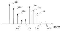
- FIG. 11 is a diagram illustrating a configuration in the vicinity of an i-th symbol of a reception signal received by a reception unit b102-n R. Is a diagram illustrating a code vector d u. It is a figure which shows an example of the waveform obtained by performing frequency time conversion, such as IFFT, to a temporary CFR estimated value, and extracting only the path
- frequency time conversion such as IFFT
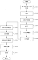
- FIG. 4 is a schematic block diagram showing a configuration of a path extraction unit b205-n R. It is a flowchart which shows operation
- FIG. 6 is a schematic block diagram showing a configuration of a section setting unit b305-n R.
- FIG. 5 is a schematic block diagram showing a configuration of a propagation path estimation unit b306-n R.
- FIG. It is a flowchart which shows operation
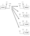
- FIG. 1 is a diagram showing an overview of a wireless communication system according to the first embodiment of the present invention.
- the wireless communication system includes a transmission device a1, a reception device b1, and reception devices 101 to 103.
- the transmission device a1 is, for example, a base station of a mobile communication system (sometimes referred to as “base station device”), and the reception device b1 and the reception devices 101 to 103 are terminals (“terminal device”, It may be referred to as “mobile station” or “mobile station device”.
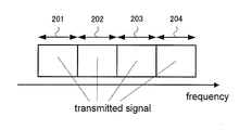
- FIG. 2 shows a transmission signal transmitted by the transmission device a1.
- Signals transmitted to the receiving device b1 and the receiving devices 101 to 103 are assigned to any one of the bands 201 to 204.
- transmission / reception from the transmission device a1 to the reception device b1 will be described.
- the band 202 is used for the signal to the receiving device b1. This may be another band.
- the number of receiving apparatuses is four and the frequency band is divided into four has been described. However, the number is not limited to four and may be arbitrary, for example, two or eight.
- the transmission device a1 includes N T transmission antennas a1-1 to a1-N T
- the reception device b1 includes N R reception antennas b1-1 to b1-N R. Therefore, the wireless communication system constitutes N T ⁇ N R MIMO, in particular, N T ⁇ N R single-user MIMO. Note that MIMO is sometimes referred to as “Mimo” or “Mimo”.
- FIG. 3 is a schematic block diagram showing the configuration of the transmission device a1.
- the transmitter a1 includes a coding unit a101, a modulation unit a102-n T , a pilot generation unit a103, a mapping unit a104-n T , a precoding unit a105, an IFFT (Inverse Fast Fourier Transform) unit a106-n T GI (Guard Interval) insertion section a107-n T and transmission section a108-n T.
- n T 1, 2,..., NT .
- the transmission antennas a1-n T are also shown.
- the encoding unit a101 encodes and encodes information bits to be transmitted to the receiving apparatus b1 using an error correction code such as a convolutional code, a turbo code, and an LDPC (Low Density Parity Check) code. Generate bits.
- the encoding unit a101 outputs the generated encoded bits to the modulation unit a102-n T. Thereafter, the number of streams of the signal to be transmitted to the receiving apparatus b1 and U, of the N T modulation unit a102-n T, using U number only.
- U is the number of transmission streams. Note that a single signal sequence may be generated by serial-parallel conversion of the output of one modulation unit.
- the modulation unit a102-n T modulates the coded bits input from the coding unit a101 using a modulation scheme such as PSK (Phase Shift Keying) or QAM (Quadrature Amplitude Modulation), Generate modulation symbols.
- Modulation unit a102-u outputs the generated modulation symbols to mapping section a104-n T.
- Pilot generation unit a103 the receiving device b1 is a reference signal for propagation path estimation, and generating pilot symbols U street, and outputs to the mapping section a104-n T. Pilot generation section a103 also generates a reference signal for receiving apparatuses 101 to 103 to perform propagation path estimation. Details will be described in conjunction with the mapping unit a104-n T.
- the mapping unit a104-n T converts the modulation symbols input from the modulation unit a102-n T and the pilot symbols input from the pilot generation unit a103 into resource elements (time-frequency band) based on predetermined mapping information. ) generates a signal in the frequency domain are mapped, and outputs a signal of the generated frequency domain referred to as IFFT unit (frequency-time conversion unit) to a106-n T.
- the resource element is a unit in which a modulation symbol, which is composed of one subcarrier and one FFT section described later, is arranged in a frame transmitted by the transmission apparatus a1.
- the mapping information is determined by the transmission device a1, and is notified in advance from the transmission device a1 to the reception device b1.
- Precoding section a105 performs a precoding the modulation symbols and pilot symbols input from the mapping unit a104-n T. Note that precoding is not performed for CRS. Then outputs to the IFFT unit a106-n T.
- the IFFT unit a106-n T performs frequency-time conversion on the frequency domain signal input from the precoding unit a105 to generate a time domain signal.
- a time interval of a unit for performing IFFT is referred to as an FFT interval.
- the IFFT unit a106-n T outputs the generated time domain signal to the GI insertion unit a107-n T.
- the GI insertion unit a107-n T adds a GI for each signal in the FFT interval to the time domain signal input from the IFFT unit a106-n T.
- the GI is a copy of a part of the rear of the signal in the FFT interval.
- it is good also as a known signal area using a zero area, a Golay code, etc.
- the GI insertion unit a107-n T adds such a signal to the front of the signal in the FFT interval.
- a signal in the OFDM symbol section is called an OFDM symbol.
- the GI insertion unit a107-n T outputs the signal with the GI added to the transmission unit a 108-n T.
- GI may be inserted behind the FFT interval.
- GI is also called a cyclic prefix (CP).
- the transmission unit a108-n T performs digital / analog (DA) conversion on the signal input from the GI insertion unit a107-n T and shapes the waveform of the converted analog signal.
- the transmission unit a108-n T up-converts the waveform-shaped signal from the baseband to the radio frequency band, and transmits the signal from the transmission antenna a1-n T to the reception device b1.
- DA digital / analog
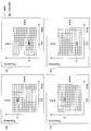
- FIG. 4 is an example in which the mapping unit a104-n T maps modulation symbols and pilot symbols, and shows a case where CRS (Cell Specific Reference Signal) is inserted as a pilot symbol in LTE-A or LTE.
- CRS Cell Specific Reference Signal
- One square represents a resource element. As seen in each of 401 to 404 in the figure, 14 squares are arranged in the time direction and 12 are arranged in the frequency direction.
- the resource element is a unit composed of one subcarrier on the frequency axis and one symbol section on the time axis in the signal transmitted by the transmission device a1. A unit in which 14 units in the time direction and 12 units in the frequency direction are arranged is called a subframe.
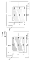
- FIG. 5 shows an example in which the mapping unit a104-n T maps modulation symbols and pilot symbols, and shows a case where DMRS is inserted as a pilot symbol in LTE-A.
- the mapping unit a104-n T maps modulation symbols and pilot symbols, and shows a case where DMRS is inserted as a pilot symbol in LTE-A.
- 501 in FIG. 5 for each subcarrier (1, 6, 11) in which DMRS is arranged, there are four resource elements in the subframe in which DMRS can be arranged. In these four resource elements, pilot symbols of up to four streams are pre-coded and then code-multiplexed and inserted. Also, an insertion pattern 502 in FIG. 5 is prepared, and pilot symbols for other streams can be inserted, so that a maximum of 8 streams can be multiplexed.
- CRS is inserted in all bands 201 to 204, but DMRS is inserted only in the allocated band. That is, the DMRS to the receiving apparatus b1 is inserted only in the band 202.
- the first pilot symbol is used for path position detection and the second pilot symbol is used as a pilot symbol for channel impulse response estimation.
- the first pilot symbol is used as CRS, Will be described as DMRS.
- the present invention is not limited to this, and any pilot arrangement in which the first pilot symbol and the second pilot symbol are different is included in the present invention.
- different arrangements may be arranged in different resource elements such as different frequencies and times.
- the pilot symbol sequence can be a second pilot symbol sequence.
- the first pilot symbol may be CSI-RS (CSI-Reference Signal) of LTE-A shown in FIG. 6 instead of CRS.
- CSI-RS is a pilot symbol used to feed back channel conditions to a base station.
- FIG. 6 shows an example of CSI-RS.
- two resource elements for arranging CSI-RS are prepared in one subframe, and two streams are code-multiplexed and inserted. To do. Since four of them are prepared, up to 8 streams can be inserted.
- CSI-RS is inserted in the entire band in the same manner as CRS.
- the pilot symbol may not be LTE-A.
- first pilot symbol and the second pilot symbol are inserted in the same subframe, but each may be inserted in a temporally different subframe. .
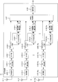
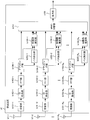
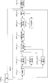
- FIG. 7 is a schematic block diagram showing the configuration of the receiving device b1 according to this embodiment.
- the receiving device b1 includes a receiving unit b101-n R , a GI removing unit b102-n R , an FFT unit (also referred to as a time frequency converting unit) b103-n R , a demapping unit b104-n R , and a path extracting unit.
- b105-n R propagation path estimation unit b106-n R , MIMO separation unit b107, and decoding unit b108.
- n R 1,2, ⁇ , a N R.
- the receiving antenna b1-n R is also shown.
- the reception unit b101-n R receives the transmission signal transmitted by the transmission device a1 via the reception antenna b1-n R.
- the receiving unit b101-n R performs frequency conversion and analog-digital (AD) conversion on the received signal.
- the GI removal unit b102-n R removes the GI from the signal input from the reception unit b101-n R, and outputs the GI to the FFT unit b103-n R.
- the FFT unit b103-n R performs time-frequency conversion on the time domain signal input from the GI removal unit b102-n R, and outputs the converted frequency domain signal to the demapping unit b 104-n R.
- the demapping unit b104-n R performs demapping based on mapping information notified in advance from the transmission device a1, and separates data and pilot symbols.
- the separated first pilot symbol is output to path extraction section b105-n R
- the second pilot symbol is output to propagation path estimation section b106-n R
- the data is output to MIMO separation section b107.
- the path extraction unit b105-n R calculates path information using the first pilot symbol input from the demapping unit b104-n R, and outputs the path information to the propagation path estimation unit b106-n R. Specific processing will be described later with reference to FIG.
- the propagation path estimation unit b106-n R uses the second pilot symbol input from the demapping unit b104-n R and the path information input from the path extraction unit b105-n R to generate the second CFR estimation value. Is output to the MIMO separation unit b107. Specific processing will be described later with reference to FIG.
- the MIMO separation unit b107 uses the U second CFR estimation values input from the propagation path estimation unit b106-n R , that is, the QR second CFR estimation values, and uses a ZF (Zero Forcing) criterion, an MMSE. (Minimum Mean Square Error) Calculates filter coefficients such as criteria and performs MIMO separation. Alternatively, separation may be performed using nonlinear processing such as MLD (Maximum Likelihood Detection) using the QR second CFR estimation values. Using these known techniques, a bit log likelihood ratio (LLR) is calculated and output to the decoding unit b108.
- ZF Zero Forcing
- MMSE Minimum Mean Square Error
- the decoding unit b108 uses, for example, the maximum likelihood decoding method (Maximum Likelihood Decoding), the maximum posterior probability (Maximum A posteriori Probability; MAP), log-MAP, Max-log using the bit LLR input from the MIMO separation unit b107.
- MAP Maximum Likelihood Decoding
- MAP maximum posterior probability
- log-MAP Max-log using the bit LLR input from the MIMO separation unit b107.
- -Decoding processing is performed using MAP, SOVA (Soft Output Viterbi Algorithm) or the like.
- FIG. 8 is a schematic block diagram showing the configuration of the path extraction unit b105-n R.
- the path extraction unit b105-n R includes a separation unit b105-n R -1, a temporary CFR (Channel Frequency Response) estimation unit b105-n R -2-n ′ T , and an FFT unit b105-n.
- R -3-n ′ T a path position extraction unit b105-n R -4-n ′ T , and a path position integration unit b105-n R -5.
- n ′ T 1, 2,..., N ′ T.
- the demultiplexing unit b105-n R ⁇ 1 demultiplexes the received signal of the resource element into which the first pilot symbol is inserted, which is input from the demapping unit b104-n R, for each stream, and divides the n ′ T-th stream. and outputs to the temporary CFR estimation unit b105-n R -2-n ' T.
- Provisional CFR estimator b105-n R- 2-n ′ T estimates the CFR of the subcarrier in which the first pilot symbol is inserted (referred to as a provisional CFR estimation value).
- the temporary CFR estimation value to output to IFFT section b105-n R -3-n ' T.
- the IFFT unit b105-n R -3-n ′ T performs frequency-time conversion on the temporary CFR estimation value input from the temporary CFR estimation unit b 105-n R -2-n ′ T , and performs a temporary channel impulse response (Channel Impulse response). Response; CIR) is converted into an estimated value.
- the temporary CIR estimation value is output to the path position extraction unit b105-n R -4-n ′ T.
- the path position extraction unit b105-n R -4-n ′ T extracts N s paths from the temporary CIR estimation values input from the IFFT unit b 105-n R -3-n ′ T in descending order of power. To do.
- the extracted path information is output to the path position integration unit b105-n R- 5.
- the value of N s may be determined at the design stage of the receiving device b1, such as 50, 60, 70, etc., or may be changed when the firmware or software of the receiving device b1 is updated at the design stage. You may do.
- the path position integration unit b105-n R -5 integrates N ′ T path information input from the path position extraction unit b105-n R -4-n ′ T, and sends it to the propagation path estimation unit b106-n R. Output. This operation will be described later together with the operation principle.
- FIG. 9 is a schematic block diagram showing the configuration of the propagation path estimation unit b106-n R.
- the propagation path estimator b106-n R includes a first CFR estimator b106-n R -1, a CIR estimator b106-n R -2-u, and a second CFR estimator b106-n R-.
- 3-u is included.
- u 1, 2,..., U max .
- U max is the maximum number of streams that can be received by the receiving apparatus b1.
- the first CFR estimator b106-n R ⁇ 1 uses the second pilot symbol input from the demapping unit b104-n R and uses the first pilot of the subcarrier in which the second pilot symbol is inserted. CFR is estimated by the number of multiplexed U streams. When the second pilot symbol is DMRS, the DMRS code-multiplexed with the target subcarrier may be solved. The estimated first CFR estimation value of the u-th stream is output to CIR estimation section b106-n R- 2-u.
- the CIR estimator b106-n R- 2-u receives the first CFR estimation value of the u-th stream input from the first CFR estimator b106-n R -1, and the path extractor b105-n R. The CIR estimation value is calculated using the path information. The calculated CIR estimation value is output to the second CFR estimation unit b106-n R- 3-u.
- the second CFR estimator b106-n R -3-u performs time-frequency conversion on the CIR estimated value input from the CIR estimator b106-n R- 2-u, and converts it into a CFR (second CFR). Called).
- the second CFR estimation unit b106-n R- 3-u outputs the calculated second CFR estimation value to the MIMO separation unit b107.
- the reception signal r nR (t) at time t received by the reception unit b102-n R is expressed by the following equations (1) to (3).
- T D is the maximum delay time
- h nR, nT ( ⁇ ) is the complex amplitude at the delay time ⁇ from the transmission antenna a 1 -n T to the reception antenna b 1 -n R
- s nT (t) is the transmission antenna.
- the transmission signal from a1-n T , z nR (t) is the noise at the reception antenna b1-n R , s nT, i (t) is the transmission signal from the transmission antenna a1-n T for the i-th symbol only, and N is The number of FFT points, S nT , i, n is a modulated signal from the transmission antenna a1-n T of the n-th subcarrier of the i-th symbol, TG is the guard interval length, T s is the length of the OFDM symbol section, ⁇ f Is a frequency interval between subcarriers.
- tau 0 complex amplitude h nR of ⁇ T D, nT ( ⁇ ) collectively referred to as the channel impulse response.
- modeling is performed on the assumption that the preceding wave of the transmission signal and the reception signal is synchronized, and there is no channel fluctuation within the subframe.
- Figure 10 shows the transmitted signal s nT from the transmitting antennas a1-n T i th symbol, the configuration of the i (t).
- the transmission signal s nT (t) is configured in such a way that these OFDM symbols are arranged in time.
- a reception signal in the digital domain is obtained by the reception unit b101-n R , the GI is removed by the GI removal unit b102-n R , and time-frequency conversion is performed by the FFT unit b103-n R.
- the received signal R nR, i, n of the n-th subcarrier in the i-th symbol obtained is expressed by the following equations (4) to (5).
- S nT , i, n are signals output from the precoding unit a105 in the transmission device a1 in FIG.
- H n the CFR matrix N R ⁇ N T is S i
- n is the transmitted signal vector of the N T ⁇ 1
- Z i is N noise vector R ⁇ 1
- X T represents a transpose of X
- the N T ⁇ U precoding matrix V is expressed by the following equation (9). Note that precoding is preferable in terms of improving transmission characteristics, but the case where precoding is not performed is also included in the present invention.
- the received signal vector R i, n can be rewritten as the following equations (10) to (13).
- H v, nR, nT, n that is a CFR after being affected by precoding may be estimated and used.
- second CFR estimated values H ′′ v, nR, nT, n which are estimated values of H v, nR, nT, n used for demodulation, are obtained, and the remaining functions of receiving apparatus b1 Will be explained.
- the operating principles of the path extraction unit b105-n R and the propagation path estimation unit b106-n R that estimate H ′′ v, nR, nT, n will be described later.
- the MIMO separation unit b107 uses the following equations (14) and (15) for the separated symbols c ′ u, i, n in the u-th stream of the i-th symbol and the n-th subcarrier. Use to calculate.
- the X H represents a complex conjugate transpose of X
- e u is the size U ⁇ 1
- the sigma 2 is the power of Z nR, i, n, c u obtained using the results of decoding, by using i, replica c '' u of n, i, n, the following equation (16) Can be estimated as follows.
- the number of subcarriers to be averaged is adjusted as appropriate. This process may be performed on a symbol that has been decoded. It should be noted that not only averaging in the subcarrier direction as in equation (16), but also averaging with respect to symbols (average with respect to i), or performing weighted averaging that forgets past results at that time. Good. Also, as c ′′ u, i, n , a soft replica created using the output result of the decoding unit b108 may be used, or a hard replica obtained by making a hard decision on the demodulation result may be used.
- the decoding result but the demodulation result c ′′ u, i, n may be used as they are, or a hard replica obtained by hard decision thereof may be used. Further, in the case of corresponding to the pilot symbol, the pilot symbol may be used as it is.
- the MIMO separation unit b107 calculates a bit log likelihood ratio from the post-MIMO separation symbol c ′ u, i, n in Expression (14).
- An equivalent amplitude gain is used for this calculation process.
- the bit log likelihood ratio ⁇ is equal to the equivalent amplitude gain ⁇ u, i, n in the u-th stream of the i-th symbol n-th subcarrier expressed by the following equation (17): It represents with following Formula (18) and (19).
- the equations (18) and (19) are respectively expressed by bit log likelihood ratios ⁇ (1) of the bits b u, i, n, 0 of the first bit and bits b u, i, n, 1 of the second bit.
- the first CFR estimation unit b106-n R ⁇ 1 calculates the first CFR estimation value using the DMRS inserted as shown in FIG.
- DMRSs of the first, second, fifth, and seventh streams are inserted into the pattern 501 in FIG. 5, and DMRSs of the third, fourth, sixth, and eighth streams are inserted into the pattern 502.
- DMRSs of the first, second, fifth, and seventh streams are inserted will be described with reference to 501 in FIG.
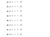
- DMRS code multiplexing is performed using four resource elements of the same subcarrier. If the code vector of the u-th stream of size 4 ⁇ 1 is d u , the signal of each resource element of the subcarrier into which DMRS 501 in FIG. 5 is inserted is expressed by the following equation (20).
- cp , u, n is a pilot symbol in the n-th subcarrier of the u-th stream, and n is limited to 1, 5, and 11 with reference to 501 in FIG. No signal is transmitted from the first, second, fifth and seventh streams to the corresponding resource element. Further, du is represented in FIG.
- the received signal received receiving antenna b1-n R is the resource element represented by the formula (20), with reference to equation (10), the following equation (21).
- the first CFR estimation value H 'v, nR, u, n can be obtained by multiplying the code vector d u to the received signal vector of the formula (21), the following equation (22), (23 ).
- n 1 ,..., N P are pilot subcarriers, and P is the number of pilot subcarriers.
- P is the number of pilot subcarriers.
- F is a P ⁇ L discrete Fourier transform matrix
- L is an assumed maximum discrete delay time. L only needs to satisfy L> D, and a larger value may be set. For example, it may be set GI points N g, it may be set to a value greater than that.
- the CIR estimation vector hv, nR, u is expressed by the following equations (29) and (30) using MMSE.
- E [X] represents the ensemble average of X
- the diagonal elements of Cv , h represent PDP.
- C v, h is obtained by a path extraction unit b105-n R described later.
- the second CFR estimator b106-n R- 3-u performs time-frequency conversion on the CIR estimated value input from the CIR estimator b106-n R- 3-u to obtain the second CFR estimated value H ′.
- 'Estimate v, nR, u, n This can be obtained by the following equations (31) and (32).
- the CFR estimated value H ′′ v, nR, u, n is output.
- the operation of the path extraction unit b105-n R will be described with reference to FIG. Separating section b105-n R -1, the first pilot symbol to separate the received signals of the resource elements are arranged at a first n 't stream.
- the CRS of the first stream is the gray resource element in 401, and in the case of the second stream, the gray resource element in 402 is extracted, and the temporary CFR estimator b105-n R -2-n 'Output to t .
- cn′T, i, n is CRS, and is valid only when the symbol number i and the subcarrier number are in the gray position in FIG.
- a temporary CFR estimation value is calculated using Equation (33) at each position, and the two are averaged. Use things in the future.
- the temporary CFR estimation values H ′ nR, n′T, n obtained by the equation (33) are subjected to frequency time conversion such as IFFT. Further, only paths with discrete delay times 0 to L ⁇ 1 are extracted.
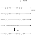
- the path position integration unit b105-nR-5 integrates the input N ′ T path position information. Specifically, if the discrete delay time d is extracted in any of the 1 to N ′ T streams, the position d is extracted even if it is not extracted in other streams. . For example, they are integrated as shown in FIG.
- ⁇ is a hyper parameter, and a fixed value such as 0.5 or 0.25 may be assigned. Every time the equation (29) is calculated, a known technique such as an EM (Expectation Maximization) algorithm is used. You may optimize.
- EM Engineering Maximization
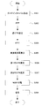
- FIG. 15 is a flowchart showing the operation of the receiving apparatus according to this embodiment. The operation shown in this figure is processing after the receiving unit b101-n R in FIG. 7 outputs the received signal to the GI removing unit b102-n R.
- Step S101 The GI removal unit b102-n R removes the GI from the received signal. Then, it progresses to step S102.
- Step S102 The FFT unit b103-n R performs time frequency conversion on the signal obtained in step S101.
- the demapping unit b104-n R separates the received signal of the resource element to which the data, the first pilot symbol, and the second pilot symbol are transmitted from the obtained frequency domain signal.
- the received signal of the resource element to which data is transmitted is transmitted to the MIMO separation unit b107, and the received signal of the resource element to which the first pilot symbol is transmitted is transmitted to the path extraction unit b105-n R.
- the reception signal of the resource element is output to the propagation path estimation unit b106-n R.
- the separation unit b105-n R ⁇ 1 of the path extraction unit b105-n R separates the reception signal of the resource element, to which the first pilot symbol is transmitted, for each transmission antenna. Thereafter, the process proceeds to step S103.
- Step S103 The provisional CFR estimation unit b105-n R- 2-n ′ T calculates a provisional CFR estimation value in the resource element to which the first pilot symbol is transmitted for each transmission antenna. Thereafter, the process proceeds to step S104.
- Step S104 The IFFT unit b105-n R- 3-n ′ T performs frequency-time conversion on the temporary CFR estimated value obtained in Step S103, and converts it into a temporary CIR estimated value. Thereafter, the process proceeds to step S105.
- Step S105 The path position extraction unit b105-n R -4-n ′ T extracts a predetermined number of paths in descending order of power from the temporary CIR estimation values obtained in Step S104. Thereafter, the process proceeds to step S106.
- Step S106 The path position integration unit b105-n R -5 integrates the path position for each transmission antenna obtained in step S105. Thereafter, the process proceeds to step S107.
- Step S107 The first CFR estimator b106-n R ⁇ 1 of the propagation path estimator b106-n R (FIG. 9) receives the received signal of the resource element to which the second pilot symbol obtained in Step S102 is transmitted. Is used to calculate the first CFR estimate. Thereafter, the process proceeds to step S108.
- Step S108 The CIR estimation unit b106-n R- 2-u calculates a CIR estimation value using the path position information obtained in Step S106 and the first CFR estimation value obtained in Step S107. Thereafter, the process proceeds to step S109.
- Step S109 The second CFR estimator b106-n R -3-u performs time-frequency conversion on the CIR estimated value obtained in step S108, and converts it to a second CFR estimated value. Then, it progresses to step S110.
- Step S110 The MIMO separation unit b107 performs MIMO separation using the received signal of the resource element to which the data obtained in step S102 is transmitted and the second CFR estimation value obtained in step S109, and performs coding bit LLR is calculated. Thereafter, the process proceeds to step S111.
- Step S111 The decoding unit b108 performs decoding using the LLR of the encoded bit obtained in step S110. Thereafter, the receiving device b1 ends the operation.
- the PDP setting unit operates as a path extraction unit, and extracts a path effective for estimation using the first pilot symbol.
- the propagation path estimation unit calculates a first CFR estimation value using the second pilot symbol, and calculates a CIR estimation value using the path position information extracted by the path extraction unit and the first CFR estimation value. And then converted to a second CFR estimate.
- the receiving apparatus b1 includes N R path extraction units b105-n R as shown in FIG. 7, but the number may be one.
- the path information extracted by one path extraction unit can be shared by all of the propagation path estimation units b106-n R.
- the present embodiment is applied to a receiving apparatus that performs interference cancellation processing using a CIR estimation value.
- a form of propagation path estimation technique may be applied.
- the transmission device a1 maps and transmits the first pilot symbol and the second pilot symbol in the frequency domain
- the reception device b1 uses the first pilot symbol to obtain the provisional CIR estimation.
- a predetermined number of paths are extracted in descending order of power.
- a second CFR estimation value is calculated using the second pilot symbol and the obtained path information.
- the propagation path adaptability of a path is calculated one by one and the paths are extracted in descending order of the propagation path adaptability.
- the configuration of the transmission device a2 according to the present embodiment is the same as that of the transmission device a1 according to the first embodiment, description thereof is omitted.
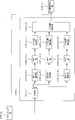
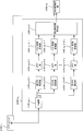
- FIG. 16 is a schematic block diagram showing the configuration of the receiving device b2 according to this embodiment.
- the path extraction unit b205-n R is different.
- other functions reception unit b101-n R , GI removal unit b102-n R , FFT unit b103-n R , demapping unit b104-n R , propagation path estimation unit b106-n R , MIMO separation unit b107, The operation of the decoding unit b108) is the same as that of the receiving device b1.
- the description of the same operation as that of the first embodiment is omitted.
- FIG. 17 is a schematic block diagram showing the configuration of the path extraction unit b205-n R.
- a path extraction unit b 205-n R in FIG. 17 is compared with the path extraction section b105-n R in FIG. 8, IFFT unit b105-n R -3-n ' T, the path position extracting section b105-n R -4 ⁇ n ′ T , path location integration unit b105-n R ⁇ 5 is not provided, test CIR estimation unit b205-n R ⁇ 3, propagation path fitness calculation unit b205-n R ⁇ 4, unnecessary candidate path removal unit b205 ⁇ n R ⁇ 5, determination unit b205-n R ⁇ 6, and path determination unit b205-n R ⁇ 7.
- the path extraction unit b105-n R includes a primary storage location (not shown for easy viewing of the drawing), and includes “selected path (selected_path)”, “candidate path (candidate_path)”, “previous one”. “Channel propagation match (channel_match_prev)” and “Channel propagation match (channel_match)” are stored.
- the test CIR estimator b205-n R -3 calculates the CIR estimated value when one element of the “candidate_path” is added to the path stored in the “selected path (selected_path)”, It is calculated using the temporary CFR estimation value input from the temporary CFR estimation unit b105-n R -2-n ' T. That is, CIR estimation is performed for the number of elements of “candidate_path”.
- the calculated test CIR estimated value and the provisional CFR estimated value used for the calculation are output to the propagation path adaptability calculating unit b205-n R -4.
- the propagation path fitness calculation unit b205-n R -4 receives the temporary CFR estimation value input from the test CIR estimation unit b205-n R -3 and the test CIR estimation value for the number of elements of “candidate_path”. And the propagation path matching degree in each case is calculated and stored in “propagation path matching degree (channel_match)”. Details of the calculation of the propagation path suitability will be described later.
- the propagation path fitness calculation unit b205-n R -4 outputs the calculated propagation path fitness to the unnecessary candidate path removal unit b205-n R -5.
- the unnecessary candidate path removal unit b205-n R -5 compares the input propagation path matching degree with the “preceding channel matching degree (channel_match_prev)”, and if the former is smaller than the latter, the small propagation The channel matching level is deleted from the content of “propagation channel matching level (channel_match)”.
- the unnecessary candidate path removal unit b205-n R -5 also deletes the element of “candidate_path” corresponding to the small propagation path fitness. Thereafter, the “candidate_path” after the deletion is output to the determination unit b205-n R- 6.
- the determination unit b205-n R- 6 determines whether or not to continue the path extraction process. If the number of elements of the “candidate_path” input from the unnecessary candidate path removing unit b205-n R- 5 is smaller than the predetermined number, the path extraction process is terminated, and “selected path (selected_path ) "to output to channel estimation section b106-n R a path number stored and path numbers stored in the" candidate path (Candidate_path) "as the path information. Otherwise, “candidate_path” is output to the path determination unit b205-n R ⁇ 7. Note that the predetermined number used here may be determined at the design stage of the receiving device b2, or may be updated when the firmware or software of the receiving device b2 is updated. In particular, when the predetermined number is 1, path extraction is performed until there is no “candidate_path”.
- the path determination unit b205-n R -7 selects the maximum one of the propagation path matching degrees stored in the “propagation path matching degree (channel_match)”.
- the “candidate path (candidate_path)” corresponding to the selected propagation path fitness is determined as a new extraction path and stored in the “selected path (selected_path)”. Further, the selected propagation path matching degree is stored in “previous propagation path matching degree (channel_match_prev)”.
- the “selected path (selected_path)” of the primary storage location is emptied, the “candidate_path” of the primary storage location is set to 0 to L, and the “adjacent propagation path suitability” of the primary storage location Let (channel_match_prev) "be a small value (eg, negative infinity). Note that L is the assumed maximum delay time as in the first embodiment.
- Test CIR estimation vector h q, nR, n from transmitting antenna n ′ T when one path of “candidate_path” is added to the path stored in “selected path (selected_path)” 'T is estimated.
- the MMSE method of Expression (29) may be used.
- the CFR estimation vector in the equation (29) is changed to one having the temporary CFR estimation value obtained in the equation (33) as an element (H nR, n′T ), and the discrete Fourier in the equation (29) is used.
- the transformation matrix F changes the definition in equation (25). Specifically, n 1 , n 2 ,..., N P in the equation (25) are changed to subcarrier numbers obtained by estimating the temporary CFR in the equation (33).
- the first term of the equation (36) is an evaluation value of an error between the temporary CFR estimated value and the CIR estimated value calculated at the time of the q pass number, and specifically uses cross-correlation.
- the second term represents a penalty for increasing the number of passes.
- x is a parameter that determines the magnitude of the penalty.
- a natural logarithm value of 2 or the number of subcarriers in which pilot symbols are arranged may be used.
- the case 2 is AIC (Akaike Information Criteria)
- BIC Bayesian Information Criteria
- FIG. 18 is a flowchart showing the operation of the receiving apparatus according to this embodiment. The operation shown in this figure is processing after the receiving unit b101-n R in FIG. 16 outputs the received signal to the GI removing unit b102-n R.
- Step S201 The GI removal unit b102-n R removes the GI from the received signal. Thereafter, the process proceeds to step S202.
- Step S202 The FFT unit b103-n R performs time-frequency conversion on the signal obtained in Step S201.
- the demapping unit b104-n R separates the received signal of the resource element to which the data, the first pilot symbol, and the second pilot symbol are transmitted from the obtained frequency domain signal.
- the received signal of the resource element to which data is transmitted is transmitted to the MIMO separation unit b107, and the received signal of the resource element to which the first pilot symbol is transmitted is transmitted to the path extraction unit b205-n R.
- the reception signal of the resource element is output to the propagation path estimation unit b106-n R.
- the separation unit b105-n R ⁇ 1 of the path extraction unit b205-n R separates the received signal of the resource element to which the first pilot symbol is transmitted for each transmission antenna. Then, it progresses to step S203.
- Step S203 The provisional CFR estimation unit b105-n R- 2-n ′ T calculates a provisional CFR estimation value in the resource element to which the first pilot symbol is transmitted for each transmission antenna. Thereafter, the process proceeds to step S204.
- Step S204 The test CIR estimation unit b205-n R -3 adds the respective elements of “candidate_path” to the path number stored in the “selected path (selected_path)”. Calculate an estimate. Thereafter, the process proceeds to step S205.
- Step S205 The propagation path matching degree calculation unit b205-n R -4 uses the temporary CFR estimated value obtained in step S203 for each of the test CIR estimated values obtained in step S204 to set the “propagation degree (channel_match ) ”Is calculated. Thereafter, the process proceeds to step S206.
- Step S206 The unnecessary candidate path removal unit b205-n R -5 is an element that is less than the “preceding channel match (channel_match_prev)” of the “channel match (channel_match)” obtained in step S205. Is selected and the element of the candidate path corresponding to the element is deleted. Thereafter, the process proceeds to step S207.
- Step S207 If the number of elements of the “candidate_path” is less than the predetermined number as a result of Step S206, the determination unit b205-n R- 6 is stored in the “selected path (selected_path)”. the path number and the path number stored in the "candidate path (candidate_path)" who is to output to channel estimation section b106-n R as the path information. Thereafter, the process proceeds to step S209. If the condition is not met, the process proceeds to step S208.
- Step S208 The path determination unit b205-n R -7 selects the “candidate_path” element corresponding to the largest one among the “propagation channel match (channel_match)” elements, To the selected path (selected_path) ". In other words, the path number that has been selected is deleted from the "candidate path (candidate_path)". Thereafter, the process returns to step S204.
- Step S209 The first CFR estimator b106-n R ⁇ 1 of the propagation path estimator b106-nR uses the received signal of the resource element to which the second pilot symbol obtained in Step S202 is transmitted. 1 CFR estimate is calculated. Thereafter, the process proceeds to step S210.
- Step S210 The CIR estimating unit b106-n R- 2-u calculates a CIR estimated value using the path position information obtained in Step S207 and the first CFR estimated value obtained in Step S209. Then, it progresses to step S211.
- Step S211 The second CFR estimator b106-n R -3-u performs time-frequency conversion on the CIR estimated value obtained in Step S210 and converts it to a second CFR estimated value. Thereafter, the process proceeds to step S212.
- Step S212 The MIMO separation unit b107 performs MIMO separation using the received signal of the resource element to which the data obtained in step S202 is transmitted and the second CFR estimation value obtained in step S211 and LLR is calculated. Thereafter, the process proceeds to step S213.
- Step S213 The decoding unit b108 performs decoding using the LLR of the coded bit obtained in step S212. Thereafter, the receiving device b2 ends the operation.
- the path extraction unit can prevent unnecessary paths from being extracted by extracting the paths that improve the channel matching degree one by one. For this reason, the channel estimation accuracy is improved, and the accuracy of MIMO separation can be improved by using the channel estimation value with improved accuracy.
- the path determination unit b205-n R -7 determines the number of paths determined by one iteration process, but may be larger than that. For example, in the case of 3, Then, three paths are extracted in descending order of propagation path adaptability. In this case, the channel matching degree when three paths are added is calculated, and the channel matching degree is stored in the “preceding channel matching degree (channel_match_prev)”.
- the receiving device b2 includes N R path extraction units b205-n R as illustrated in FIG. 16 has been described.
- the number may be one.
- the path information extracted by one path extraction unit is shared by all of the propagation path estimation units b106-n R.
- the transmission device a1 maps and transmits the first pilot symbol and the second pilot symbol in the frequency domain
- the reception device b1 uses the first pilot symbol to obtain the provisional CIR estimation.
- a predetermined number of paths are extracted in descending order of power.
- to calculate a second CFR estimation value using the path information obtained with the second pilot symbol a case will be described in which a continuous PDP is set from the obtained path information and the second CFR estimated value is calculated using a frequency correlation that can be calculated from the PDP.
- the configuration of the transmission device a3 according to the present embodiment is the same as that of the transmission device a1 according to the first embodiment, description thereof is omitted.
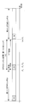
- Figure 19 is a schematic block diagram showing the configuration of a receiving apparatus b3 according to the present embodiment. 19 is compared with the receiving device b1 in FIG. 7, the path setting unit b305-n R is provided instead of the path extracting unit b105-n R , and the propagation path estimating unit b306-n R is different. However, other functions (reception unit b101-n R , GI removal unit b102-n R , FFT unit b103-n R , demapping unit b104-n R , MIMO separation unit b107, decoding unit b108) It is the same as the receiving device b1. The description of the same operation as that of the first embodiment is omitted.
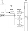
- FIG. 20 is a schematic block diagram showing the configuration of the section setting unit b305-n R.
- a section setting unit B 305-n R in FIG. 20 is compared with the path extraction section b105-n R 8, the path position extracting section b105-n R -4-n ' T and the path integration unit b105-n R - 5 and a path / section conversion unit b305-n R -4-n ′ T and a frequency correlation calculation unit b305-n R -5.
- the operations of other functions (separation unit b105-n R -1, provisional CFR estimation unit b105-n R -2-n ' T , IFFT unit b105-nR-3-n' T ) Is the same.
- the description of the same operation as that of the first embodiment is omitted.
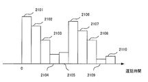
- the path / section conversion unit b305-n R- 4-n ′ T converts the temporary CIR estimation value input from the IFFT unit b105-nR-3-n ′ T into a continuous value PDP. Specifically, when the provisional CIR estimates were as shown in FIG. 13, it converts as shown in FIG. 21. For example, the section 2101 has been converted from the path 1301, and if the power of the path 1301 is a, the height of the section 2101 is a / ⁇ t, and the horizontal width of the section 2101 is ⁇ t . The PDP thus obtained, and outputs it to the frequency correlation calculating unit b305-n R -5.
- the frequency correlation calculation unit b305-n R -5 first averages the PDPs input from the path / conversion unit b305-n R -4-n ′ T. Then, to calculate the frequency correlation from averaged PDP, and outputs the propagation channel estimation unit b306-n R. Details of the frequency correlation calculation method will be described later.
- Figure 22 is a schematic block diagram showing the configuration of a channel estimation unit b306-n R.
- the second CFR estimation value is calculated from the frequency correlation value input from, and output to the MIMO separation unit b107.
- the second CFR estimation vector H ′′ v, nR, u calculated by the equation (31) is expressed by the following equations (37) to (39).
- H ′ v, nR, u is the first CFR estimation value as in the first embodiment
- ⁇ n, m is the frequency correlation between subcarriers n and m. If the PDP with the horizontal axis as the delay time ⁇ is C ( ⁇ ), ⁇ n, m is expressed by the following equation (40).
- ⁇ n, m is input from the section setting unit.
- FIG. 23 is a flowchart showing the operation of the receiving apparatus according to this embodiment. The operation shown in this figure is processing after the reception unit b101-n R in FIG. 19 outputs the reception signal to the GI removal unit b102-n R.
- Step S301 GI removal unit b 102-n R removes GI from the received signal. Thereafter, the process proceeds to step S302.
- Step S302 FFT unit b103-n R performs a time-frequency conversion on the signal obtained at step S301.
- the demapping unit b104-n R separates the received signal of the resource element to which data, the first pilot symbol, and the second pilot symbol are transmitted from the obtained frequency domain signal.
- the received signal of the resource element to which data is transmitted is transmitted to the MIMO separation unit b107, the received signal of the resource element to which the first pilot symbol is transmitted is transmitted to the section setting unit b305-n R , and the second pilot symbol is transmitted.
- the reception signal of the resource element is output to the propagation path estimation unit b306-n R.
- the separation unit b105-n R ⁇ 1 of the section setting unit b305-nR separates the reception signal of the resource element, to which the first pilot symbol is transmitted, for each transmission antenna. Thereafter, the process proceeds to step S303.
- Step S303 The provisional CFR estimation unit b105-n R- 2-n ′ T calculates a provisional CFR estimation value in the resource element to which the first pilot symbol is transmitted for each transmission antenna. Thereafter, the process proceeds to step S304.
- Step S304 The IFFT unit b105-n R -3-n ′ T performs frequency-time conversion on the temporary CFR estimated value obtained in Step S303, and converts it into a temporary CIR estimated value. Thereafter, the process proceeds to step S305.
- Step S305 The frequency correlation calculation unit b305-n R -5 converts the temporary CIR estimation value obtained in step S304 into a PDP, and calculates a frequency correlation from the converted PDP. Thereafter, the process proceeds to step S306.
- Step S306 The first CFR estimator b106-n R ⁇ 1 of the propagation path estimator b306-n R uses the received signal of the resource element to which the second pilot symbol obtained in Step S302 is transmitted, A first CFR estimate is calculated. Thereafter, the process proceeds to step S307.
- Step S307 The second CFR estimator b306-n R- 2-u uses the frequency correlation obtained in Step S305 and the first CFR estimated value obtained in Step S306 to generate the second CFR estimated value. Is calculated. Thereafter, the process proceeds to step S308.
- Step S308 The MIMO separation unit b107 performs MIMO separation using the received signal of the resource element to which the data obtained in step S302 is transmitted and the second CFR estimation value obtained in step S307, LLR is calculated. Thereafter, the process proceeds to step S309.
- Step S309 The decoding unit b108 performs decoding using the LLR of the encoded bit obtained in step S308. Thereafter, the receiving device b3 ends the operation.
- the PDP setting unit calculates the temporary CIR estimated value using the first pilot symbol, converts the calculated temporary CIR estimated value into the PDP, and converts the calculated PDP from the frequency correlation. Is calculated. Also, a first CFR estimation value is calculated using the second pilot symbol. A second CFR estimated value is calculated using these frequency correlations and the first CFR estimated value.
- the path extraction in the first embodiment or the second embodiment may be performed to reduce the number of paths and then convert to PDP.
- the present invention is not limited to MIMO. If it is not MIMO, the estimated second CFR estimation value is used for propagation path compensation.
- the path extraction unit b105-n R and the propagation path estimation unit b106-n R may be realized by a computer.
- the program for realizing the control function may be recorded on a computer-readable recording medium, and the program recorded on the recording medium may be read by a computer system and executed.
- the “computer system” here is a computer system built in the transmission device a1 or the reception devices b1 to b3, and includes hardware such as an OS and peripheral devices.
- the “computer-readable recording medium” refers to a storage device such as a portable medium such as a flexible disk, a magneto-optical disk, a ROM, and a CD-ROM, and a hard disk built in the computer system.
- the “computer-readable recording medium” is a medium that dynamically holds a program for a short time, such as a communication line when transmitting a program via a network such as the Internet or a communication line such as a telephone line,
- a volatile memory inside a computer system serving as a server or a client may be included and a program that holds a program for a certain period of time.
- the program may be a program for realizing a part of the functions described above, and may be a program capable of realizing the functions described above in combination with a program already recorded in a computer system.
- part or all of the transmission device a1 and the reception devices b1 to b3 in the above-described embodiment may be realized as an integrated circuit such as an LSI (Large Scale Integration).
- LSI Large Scale Integration
- Each functional block of the transmission device a1 and the reception devices b1 to b3 may be individually made into a processor, or a part or all of them may be integrated into a processor.
- the method of circuit integration is not limited to LSI, and may be realized by a dedicated circuit or a general-purpose processor. Further, in the case where an integrated circuit technology that replaces LSI appears due to progress in semiconductor technology, an integrated circuit based on the technology may be used.
Landscapes
- Engineering & Computer Science (AREA)
- Signal Processing (AREA)
- Computer Networks & Wireless Communication (AREA)
- Power Engineering (AREA)
- Radio Transmission System (AREA)
Priority Applications (1)
| Application Number | Priority Date | Filing Date | Title |
|---|---|---|---|
| US14/378,654 US9100259B2 (en) | 2012-02-16 | 2013-02-07 | Receiving device, receiving method, and receiving program |
Applications Claiming Priority (2)
| Application Number | Priority Date | Filing Date | Title |
|---|---|---|---|
| JP2012031689A JP2013168853A (ja) | 2012-02-16 | 2012-02-16 | 受信装置、受信方法および受信プログラム |
| JP2012-031689 | 2012-02-16 |
Publications (1)
| Publication Number | Publication Date |
|---|---|
| WO2013121958A1 true WO2013121958A1 (ja) | 2013-08-22 |
Family
ID=48984070
Family Applications (1)
| Application Number | Title | Priority Date | Filing Date |
|---|---|---|---|
| PCT/JP2013/052812 Ceased WO2013121958A1 (ja) | 2012-02-16 | 2013-02-07 | 受信装置、受信方法および受信プログラム |
Country Status (3)
| Country | Link |
|---|---|
| US (1) | US9100259B2 (enExample) |
| JP (1) | JP2013168853A (enExample) |
| WO (1) | WO2013121958A1 (enExample) |
Cited By (2)
| Publication number | Priority date | Publication date | Assignee | Title |
|---|---|---|---|---|
| WO2015165354A1 (zh) * | 2014-04-28 | 2015-11-05 | 电信科学技术研究院 | 一种功率时延谱pdp估计方法及装置 |
| WO2015196408A1 (zh) * | 2014-06-26 | 2015-12-30 | 华为技术有限公司 | 一种基于fbmc的导频发送方法、信道估计方法及相关装置 |
Families Citing this family (6)
| Publication number | Priority date | Publication date | Assignee | Title |
|---|---|---|---|---|
| EP2919392B1 (en) | 2014-03-11 | 2017-03-08 | Alcatel Lucent | Non-linear precoder with separate tracking |
| GB2533180B (en) | 2015-06-04 | 2018-05-30 | Imagination Tech Ltd | Minimising inter-symbol interference in OFDM signals |
| US9686114B2 (en) * | 2015-06-26 | 2017-06-20 | Futurewei Technologies, Inc. | Apparatus, method, and computer program for communicating one or more symbols with multiple pilot signals and nulls |
| US10411782B2 (en) * | 2016-03-31 | 2019-09-10 | Qualcomm Incorporated | Channel estimation for per-tone continuous precoding in downlink MIMO transmission |
| CN111565454A (zh) * | 2019-02-14 | 2020-08-21 | 索尼公司 | 电子装置、无线通信方法和计算机可读介质 |
| US11356299B2 (en) * | 2020-04-07 | 2022-06-07 | Qualcomm Incorporated | Transmission techniques over delay-doppler channels |
Citations (2)
| Publication number | Priority date | Publication date | Assignee | Title |
|---|---|---|---|---|
| JP2011515993A (ja) * | 2008-03-28 | 2011-05-19 | クゥアルコム・インコーポレイテッド | 低減された次数のfft及びハードウェア補間器を使用する広帯域パイロットチャネル推定 |
| JP2012044492A (ja) * | 2010-08-20 | 2012-03-01 | Sharp Corp | 受信装置、受信方法及び受信プログラム |
Family Cites Families (13)
| Publication number | Priority date | Publication date | Assignee | Title |
|---|---|---|---|---|
| US6373888B1 (en) | 1998-10-09 | 2002-04-16 | Telefonaktiebolaget Lm Ericsson (Publ) | Estimated channel with variable number of taps |
| US7701917B2 (en) * | 2004-02-05 | 2010-04-20 | Qualcomm Incorporated | Channel estimation for a wireless communication system with multiple parallel data streams |
| JP2008124942A (ja) * | 2006-11-15 | 2008-05-29 | Nec Corp | 無線通信システム、無線通信装置及びそれらに用いる有効パス検出方法 |
| US7852909B2 (en) * | 2007-05-04 | 2010-12-14 | Beceem Communications Inc. | Method and apparatus for estimating frequency offset and timing offset of one or more mobile stations (MSs) |
| US8259865B2 (en) * | 2008-03-27 | 2012-09-04 | Qualcomm Incorporated | Methods and apparatus for adapting channel estimation in a communication system |
| US9148311B2 (en) * | 2008-10-15 | 2015-09-29 | Stmicroelectronics, Inc. | Determining responses of rapidly varying MIMO-OFDM communication channels using observation scalars |
| US8767843B2 (en) * | 2008-11-10 | 2014-07-01 | Motorola Mobility Llc | Employing cell-specific and user entity-specific reference symbols in an orthogonal frequency-division multiple access |
| JP5059800B2 (ja) * | 2009-03-16 | 2012-10-31 | 株式会社エヌ・ティ・ティ・ドコモ | 無線基地局装置及び移動局装置、無線通信方法 |
| EP2449684B1 (en) * | 2009-07-02 | 2014-11-19 | Telefonaktiebolaget L M Ericsson (PUBL) | Multicarrier radio receiver and method for receiving multiple carriers |
| US8428547B2 (en) * | 2009-10-22 | 2013-04-23 | Korea Advanced Institute Of Science And Technology | Signaling in wireless communication systems |
| CN102792617A (zh) * | 2010-03-05 | 2012-11-21 | 日本电气株式会社 | 信道估计电路、信道估计方法和接收机 |
| GB2482122B (en) * | 2010-07-19 | 2014-02-19 | Intellectual Ventures Holding 81 Llc | Communication unit and pilot method for time varying channels |
| US20130343372A1 (en) * | 2012-06-22 | 2013-12-26 | Nicholas William Whinnett | Femtocell base station synchronization |
-
2012
- 2012-02-16 JP JP2012031689A patent/JP2013168853A/ja active Pending
-
2013
- 2013-02-07 WO PCT/JP2013/052812 patent/WO2013121958A1/ja not_active Ceased
- 2013-02-07 US US14/378,654 patent/US9100259B2/en not_active Expired - Fee Related
Patent Citations (2)
| Publication number | Priority date | Publication date | Assignee | Title |
|---|---|---|---|---|
| JP2011515993A (ja) * | 2008-03-28 | 2011-05-19 | クゥアルコム・インコーポレイテッド | 低減された次数のfft及びハードウェア補間器を使用する広帯域パイロットチャネル推定 |
| JP2012044492A (ja) * | 2010-08-20 | 2012-03-01 | Sharp Corp | 受信装置、受信方法及び受信プログラム |
Non-Patent Citations (1)
| Title |
|---|
| KATSUYA KATO ET AL.: "Channel Estimation Employing Highly Efficient Tap Selection based on Information Criterion for OFDM Turbo Equalization", IEICE TECHNICAL REPORT, THE INSTITUTE OF ELECTRONICS, INFORMATION AND COMMUNICATION ENGINEERS, 23 February 2011 (2011-02-23), pages 55 - 60 * |
Cited By (4)
| Publication number | Priority date | Publication date | Assignee | Title |
|---|---|---|---|---|
| WO2015165354A1 (zh) * | 2014-04-28 | 2015-11-05 | 电信科学技术研究院 | 一种功率时延谱pdp估计方法及装置 |
| WO2015196408A1 (zh) * | 2014-06-26 | 2015-12-30 | 华为技术有限公司 | 一种基于fbmc的导频发送方法、信道估计方法及相关装置 |
| CN106464629A (zh) * | 2014-06-26 | 2017-02-22 | 华为技术有限公司 | 一种基于fbmc的导频发送方法、信道估计方法及相关装置 |
| US10333757B2 (en) | 2014-06-26 | 2019-06-25 | Huawei Technologies Co., Ltd. | FBMC-based pilot sending method, channel estimation method, and related apparatuses |
Also Published As
| Publication number | Publication date |
|---|---|
| JP2013168853A (ja) | 2013-08-29 |
| US9100259B2 (en) | 2015-08-04 |
| US20150043683A1 (en) | 2015-02-12 |
Similar Documents
| Publication | Publication Date | Title |
|---|---|---|
| WO2013121958A1 (ja) | 受信装置、受信方法および受信プログラム | |
| US9806912B2 (en) | Methods and devices for channel estimation and OFDM receiver | |
| JP5337165B2 (ja) | キャリア間干渉が限定された無線通信ネットワークのチャネル推定方法及びシステム | |
| JP5400857B2 (ja) | Ldpc復号化のための装置、方法、および受信端末 | |
| JP2012142932A (ja) | 狭帯域干渉を受けるofdm信号を復号する方法 | |
| JP2012110001A (ja) | 多重アクセスネットワークにおける通信方法およびシステム | |
| JP5330599B2 (ja) | 受信通信信号を最尤検出を用いて結合的に復号するための方法及び受信機 | |
| EP2547015A1 (en) | Receiving device, receiving method, receiving program, and processor | |
| WO2012105291A1 (ja) | 受信装置、受信方法、通信システムおよび通信方法 | |
| US8503556B2 (en) | Channel estimation method | |
| CN114268352B (zh) | 一种nr上行控制信道格式1的检测方法 | |
| JP2008205697A (ja) | Mimo受信装置および受信方法 | |
| Hussein et al. | Least Square Estimation‐Based Different Fast Fading Channel Models in MIMO‐OFDM Systems | |
| CN101227252B (zh) | 未知噪声信息的多径衰落信道软判决度量生成方法 | |
| JP5539832B2 (ja) | 受信装置、受信方法、受信プログラム | |
| JP5288622B2 (ja) | 無線通信装置、無線通信システムおよび通信方法 | |
| US8446972B2 (en) | Communication system, reception device, and communication method | |
| Osinsky et al. | Data-aided ls channel estimation in massive mimo turbo-receiver | |
| JP2007037151A (ja) | Ofdm伝送システムのチャネルを推定する装置、方法、及びコンピュータプログラム | |
| JP2013223177A (ja) | 受信装置、受信方法および受信プログラム | |
| WO2012122778A1 (en) | System and method for signaling and detecting in wireless communications systems | |
| JP5837797B2 (ja) | 受信装置、受信方法、通信システムおよび通信方法 | |
| JP2010193350A (ja) | 通信装置及び通信システム | |
| JP2014116644A (ja) | 受信装置 | |
| WO2012169303A1 (ja) | 受信装置、受信方法、制御プログラムおよび集積回路 |
Legal Events
| Date | Code | Title | Description |
|---|---|---|---|
| 121 | Ep: the epo has been informed by wipo that ep was designated in this application |
Ref document number: 13749542 Country of ref document: EP Kind code of ref document: A1 |
|
| WWE | Wipo information: entry into national phase |
Ref document number: 14378654 Country of ref document: US |
|
| NENP | Non-entry into the national phase |
Ref country code: DE |
|
| 122 | Ep: pct application non-entry in european phase |
Ref document number: 13749542 Country of ref document: EP Kind code of ref document: A1 |