WO2013121958A1 - Receiving device, receiving method and receiving program - Google Patents
Receiving device, receiving method and receiving program Download PDFInfo
- Publication number
- WO2013121958A1 WO2013121958A1 PCT/JP2013/052812 JP2013052812W WO2013121958A1 WO 2013121958 A1 WO2013121958 A1 WO 2013121958A1 JP 2013052812 W JP2013052812 W JP 2013052812W WO 2013121958 A1 WO2013121958 A1 WO 2013121958A1
- Authority
- WO
- WIPO (PCT)
- Prior art keywords
- path
- unit
- pilot symbol
- estimation
- frequency
- Prior art date
Links
Images


Classifications
-
- H—ELECTRICITY
- H04—ELECTRIC COMMUNICATION TECHNIQUE
- H04L—TRANSMISSION OF DIGITAL INFORMATION, e.g. TELEGRAPHIC COMMUNICATION
- H04L5/00—Arrangements affording multiple use of the transmission path
- H04L5/003—Arrangements for allocating sub-channels of the transmission path
- H04L5/0048—Allocation of pilot signals, i.e. of signals known to the receiver
-
- H—ELECTRICITY
- H04—ELECTRIC COMMUNICATION TECHNIQUE
- H04L—TRANSMISSION OF DIGITAL INFORMATION, e.g. TELEGRAPHIC COMMUNICATION
- H04L25/00—Baseband systems
- H04L25/02—Details ; arrangements for supplying electrical power along data transmission lines
- H04L25/0202—Channel estimation
- H04L25/0204—Channel estimation of multiple channels
-
- H—ELECTRICITY
- H04—ELECTRIC COMMUNICATION TECHNIQUE
- H04L—TRANSMISSION OF DIGITAL INFORMATION, e.g. TELEGRAPHIC COMMUNICATION
- H04L27/00—Modulated-carrier systems
- H04L27/26—Systems using multi-frequency codes
- H04L27/2601—Multicarrier modulation systems
- H04L27/2647—Arrangements specific to the receiver only
-
- H—ELECTRICITY
- H04—ELECTRIC COMMUNICATION TECHNIQUE
- H04B—TRANSMISSION
- H04B7/00—Radio transmission systems, i.e. using radiation field
- H04B7/02—Diversity systems; Multi-antenna system, i.e. transmission or reception using multiple antennas
- H04B7/04—Diversity systems; Multi-antenna system, i.e. transmission or reception using multiple antennas using two or more spaced independent antennas
- H04B7/0413—MIMO systems
-
- H—ELECTRICITY
- H04—ELECTRIC COMMUNICATION TECHNIQUE
- H04L—TRANSMISSION OF DIGITAL INFORMATION, e.g. TELEGRAPHIC COMMUNICATION
- H04L25/00—Baseband systems
- H04L25/02—Details ; arrangements for supplying electrical power along data transmission lines
- H04L25/0202—Channel estimation
- H04L25/0212—Channel estimation of impulse response
-
- H—ELECTRICITY
- H04—ELECTRIC COMMUNICATION TECHNIQUE
- H04L—TRANSMISSION OF DIGITAL INFORMATION, e.g. TELEGRAPHIC COMMUNICATION
- H04L25/00—Baseband systems
- H04L25/02—Details ; arrangements for supplying electrical power along data transmission lines
- H04L25/0202—Channel estimation
- H04L25/022—Channel estimation of frequency response
-
- H—ELECTRICITY
- H04—ELECTRIC COMMUNICATION TECHNIQUE
- H04L—TRANSMISSION OF DIGITAL INFORMATION, e.g. TELEGRAPHIC COMMUNICATION
- H04L25/00—Baseband systems
- H04L25/02—Details ; arrangements for supplying electrical power along data transmission lines
- H04L25/0202—Channel estimation
- H04L25/0224—Channel estimation using sounding signals
- H04L25/0228—Channel estimation using sounding signals with direct estimation from sounding signals
-
- H—ELECTRICITY
- H04—ELECTRIC COMMUNICATION TECHNIQUE
- H04L—TRANSMISSION OF DIGITAL INFORMATION, e.g. TELEGRAPHIC COMMUNICATION
- H04L27/00—Modulated-carrier systems
- H04L27/26—Systems using multi-frequency codes
- H04L27/2601—Multicarrier modulation systems
- H04L27/2602—Signal structure
- H04L27/261—Details of reference signals
- H04L27/2613—Structure of the reference signals
Definitions
- the present invention relates to a receiving apparatus, a receiving method, and a receiving program for estimating a propagation path for demodulation in a wireless communication system such as LTE or LTE-A.
- OFDM Orthogonal Frequency Division Multiplexing
- LTE Long Termination Evolution
- LTE-A LTE-A Advanced
- CFR channel frequency response
- the receiving apparatus transmits pilot symbols in which the waveform (or the signal sequence) is stored in advance from the transmitting apparatus to the receiving apparatus.
- a highly accurate delay profile (Power Delay Profile (PDP)) is required.
- Patent Document 1 describes a method for estimating a channel impulse response.
- the method includes a two-stage process of path extraction and channel impulse response estimation using the extracted path information.
- this technique is used for OFDM, the estimated channel impulse response is subjected to time-frequency conversion to be converted into a frequency response before use.
- LTE-A uses a user-specific demodulation reference signal (Demodulation Reference Signal: DMRS) as a reference signal for estimating a propagation path for demodulation, and the reference signal exists only in the band used by the user. Therefore, there is a problem that the PDP estimation accuracy is lowered, and as a result, the propagation channel estimation accuracy is also lowered.
- DMRS Demodulation Reference Signal
- the present invention intends to provide a receiving apparatus, a receiving method, and a receiving program capable of greatly improving the propagation path estimation accuracy in wireless communication.
- the present invention receives a second pilot symbol which is a pilot symbol used for demodulation and a first pilot symbol which is a pilot symbol different from the second pilot symbol, and uses the first pilot symbol to power.
- a receiving apparatus comprising: a power delay profile setting unit that obtains a delay profile; and a propagation path estimation unit that performs the propagation path estimation using the power delay profile and the second pilot symbol.
- the first pilot symbol and the second pilot symbol are arranged in different resources.
- the first pilot symbol and the second pilot symbol have different spatial multiplexing methods.
- the first pilot symbol and the second pilot symbol have different bandwidths.
- the receiving apparatus of the present invention is characterized in that a bandwidth in which the second pilot symbol is arranged is narrower than the first pilot symbol.
- the second pilot symbol is subjected to the same precoding as that of the data signal.
- the power delay profile setting unit operates as a path extraction unit that extracts a valid path and generates path information
- the channel estimation unit uses the second pilot symbol to estimate a first frequency response that is a frequency response in a subcarrier in which the second pilot symbol is transmitted;
- a channel impulse response estimation unit that estimates a channel impulse response using the path information and the first frequency response.
- the path extraction unit uses a first pilot symbol to estimate a temporary frequency response that is a frequency response for power delay profile measurement, and the temporary frequency A frequency time conversion unit that converts a response into a temporary channel impulse response, and a path position extraction unit that extracts a predetermined number of paths from the temporary channel impulse response in descending order of power.
- the path extraction unit adds a candidate path to the selected path to estimate a test channel impulse response, calculates a propagation path fitness of the test channel impulse response, and the candidate path Among them, the ones that are lower than the channel compatibility before the addition are deleted, and a predetermined number of the channel adaptations that are not deleted are selected in descending order, and candidate paths corresponding to them are newly selected. A series of processes selected as paths are repeated until the number of candidate paths falls below a predetermined number.
- the path extraction unit evaluates an error evaluation value of a propagation path estimated value when the provisional frequency response and the candidate path are added, and the number of extracted paths. It is characterized by using the sum of the penalty for increasing.
- the propagation path estimation unit performs time-frequency conversion on the channel impulse response output from the channel impulse response estimation unit, and converts the channel impulse response into a second frequency response that is a frequency response for demodulation. It is characterized by that.
- the power delay profile setting unit calculates power of the temporary channel impulse response output from the temporary frequency response estimation unit, the frequency time conversion unit, and the frequency time conversion unit.
- the power is converted into a power delay profile, and operates as a section extraction unit including a path / section conversion unit that calculates a frequency correlation
- the propagation path estimation unit calculates a second frequency response, which is a frequency response for demodulation, using the first frequency response and the frequency correlation.
- the present invention receives a second pilot symbol that is a pilot symbol used for demodulation and a first pilot symbol that is a pilot symbol different from the second pilot symbol, and uses the first pilot symbol.
- a power delay profile setting step for obtaining a power delay profile and a channel estimation step for performing the channel estimation using the power delay profile and the second pilot symbol. is there.
- the present invention is a receiving program for causing a computer to execute the receiving method.
- the propagation path estimation accuracy can be greatly improved, and the accuracy of MIMO separation can be improved by using the propagation path estimation value with improved accuracy.
- FIG. FIG. 5 is a schematic block diagram showing a configuration of a propagation path estimation unit b106-n R. It is a figure which shows the structure of transmission signal s nT, i (t) from transmission antenna a1-n T of the i-th symbol.
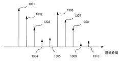
- FIG. 11 is a diagram illustrating a configuration in the vicinity of an i-th symbol of a reception signal received by a reception unit b102-n R. Is a diagram illustrating a code vector d u. It is a figure which shows an example of the waveform obtained by performing frequency time conversion, such as IFFT, to a temporary CFR estimated value, and extracting only the path
- frequency time conversion such as IFFT
- FIG. 4 is a schematic block diagram showing a configuration of a path extraction unit b205-n R. It is a flowchart which shows operation
- FIG. 6 is a schematic block diagram showing a configuration of a section setting unit b305-n R.
- FIG. 5 is a schematic block diagram showing a configuration of a propagation path estimation unit b306-n R.
- FIG. It is a flowchart which shows operation
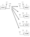
- FIG. 1 is a diagram showing an overview of a wireless communication system according to the first embodiment of the present invention.
- the wireless communication system includes a transmission device a1, a reception device b1, and reception devices 101 to 103.
- the transmission device a1 is, for example, a base station of a mobile communication system (sometimes referred to as “base station device”), and the reception device b1 and the reception devices 101 to 103 are terminals (“terminal device”, It may be referred to as “mobile station” or “mobile station device”.
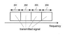
- FIG. 2 shows a transmission signal transmitted by the transmission device a1.
- Signals transmitted to the receiving device b1 and the receiving devices 101 to 103 are assigned to any one of the bands 201 to 204.
- transmission / reception from the transmission device a1 to the reception device b1 will be described.
- the band 202 is used for the signal to the receiving device b1. This may be another band.
- the number of receiving apparatuses is four and the frequency band is divided into four has been described. However, the number is not limited to four and may be arbitrary, for example, two or eight.
- the transmission device a1 includes N T transmission antennas a1-1 to a1-N T
- the reception device b1 includes N R reception antennas b1-1 to b1-N R. Therefore, the wireless communication system constitutes N T ⁇ N R MIMO, in particular, N T ⁇ N R single-user MIMO. Note that MIMO is sometimes referred to as “Mimo” or “Mimo”.
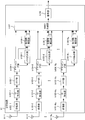
- FIG. 3 is a schematic block diagram showing the configuration of the transmission device a1.
- the transmitter a1 includes a coding unit a101, a modulation unit a102-n T , a pilot generation unit a103, a mapping unit a104-n T , a precoding unit a105, an IFFT (Inverse Fast Fourier Transform) unit a106-n T GI (Guard Interval) insertion section a107-n T and transmission section a108-n T.
- n T 1, 2,..., NT .
- the transmission antennas a1-n T are also shown.
- the encoding unit a101 encodes and encodes information bits to be transmitted to the receiving apparatus b1 using an error correction code such as a convolutional code, a turbo code, and an LDPC (Low Density Parity Check) code. Generate bits.
- the encoding unit a101 outputs the generated encoded bits to the modulation unit a102-n T. Thereafter, the number of streams of the signal to be transmitted to the receiving apparatus b1 and U, of the N T modulation unit a102-n T, using U number only.
- U is the number of transmission streams. Note that a single signal sequence may be generated by serial-parallel conversion of the output of one modulation unit.
- the modulation unit a102-n T modulates the coded bits input from the coding unit a101 using a modulation scheme such as PSK (Phase Shift Keying) or QAM (Quadrature Amplitude Modulation), Generate modulation symbols.
- Modulation unit a102-u outputs the generated modulation symbols to mapping section a104-n T.
- Pilot generation unit a103 the receiving device b1 is a reference signal for propagation path estimation, and generating pilot symbols U street, and outputs to the mapping section a104-n T. Pilot generation section a103 also generates a reference signal for receiving apparatuses 101 to 103 to perform propagation path estimation. Details will be described in conjunction with the mapping unit a104-n T.
- the mapping unit a104-n T converts the modulation symbols input from the modulation unit a102-n T and the pilot symbols input from the pilot generation unit a103 into resource elements (time-frequency band) based on predetermined mapping information. ) generates a signal in the frequency domain are mapped, and outputs a signal of the generated frequency domain referred to as IFFT unit (frequency-time conversion unit) to a106-n T.
- the resource element is a unit in which a modulation symbol, which is composed of one subcarrier and one FFT section described later, is arranged in a frame transmitted by the transmission apparatus a1.
- the mapping information is determined by the transmission device a1, and is notified in advance from the transmission device a1 to the reception device b1.
- Precoding section a105 performs a precoding the modulation symbols and pilot symbols input from the mapping unit a104-n T. Note that precoding is not performed for CRS. Then outputs to the IFFT unit a106-n T.
- the IFFT unit a106-n T performs frequency-time conversion on the frequency domain signal input from the precoding unit a105 to generate a time domain signal.
- a time interval of a unit for performing IFFT is referred to as an FFT interval.
- the IFFT unit a106-n T outputs the generated time domain signal to the GI insertion unit a107-n T.
- the GI insertion unit a107-n T adds a GI for each signal in the FFT interval to the time domain signal input from the IFFT unit a106-n T.
- the GI is a copy of a part of the rear of the signal in the FFT interval.
- it is good also as a known signal area using a zero area, a Golay code, etc.
- the GI insertion unit a107-n T adds such a signal to the front of the signal in the FFT interval.
- a signal in the OFDM symbol section is called an OFDM symbol.
- the GI insertion unit a107-n T outputs the signal with the GI added to the transmission unit a 108-n T.
- GI may be inserted behind the FFT interval.
- GI is also called a cyclic prefix (CP).
- the transmission unit a108-n T performs digital / analog (DA) conversion on the signal input from the GI insertion unit a107-n T and shapes the waveform of the converted analog signal.
- the transmission unit a108-n T up-converts the waveform-shaped signal from the baseband to the radio frequency band, and transmits the signal from the transmission antenna a1-n T to the reception device b1.
- DA digital / analog
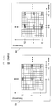
- FIG. 4 is an example in which the mapping unit a104-n T maps modulation symbols and pilot symbols, and shows a case where CRS (Cell Specific Reference Signal) is inserted as a pilot symbol in LTE-A or LTE.
- CRS Cell Specific Reference Signal
- One square represents a resource element. As seen in each of 401 to 404 in the figure, 14 squares are arranged in the time direction and 12 are arranged in the frequency direction.
- the resource element is a unit composed of one subcarrier on the frequency axis and one symbol section on the time axis in the signal transmitted by the transmission device a1. A unit in which 14 units in the time direction and 12 units in the frequency direction are arranged is called a subframe.
- FIG. 5 shows an example in which the mapping unit a104-n T maps modulation symbols and pilot symbols, and shows a case where DMRS is inserted as a pilot symbol in LTE-A.
- the mapping unit a104-n T maps modulation symbols and pilot symbols, and shows a case where DMRS is inserted as a pilot symbol in LTE-A.
- 501 in FIG. 5 for each subcarrier (1, 6, 11) in which DMRS is arranged, there are four resource elements in the subframe in which DMRS can be arranged. In these four resource elements, pilot symbols of up to four streams are pre-coded and then code-multiplexed and inserted. Also, an insertion pattern 502 in FIG. 5 is prepared, and pilot symbols for other streams can be inserted, so that a maximum of 8 streams can be multiplexed.
- CRS is inserted in all bands 201 to 204, but DMRS is inserted only in the allocated band. That is, the DMRS to the receiving apparatus b1 is inserted only in the band 202.
- the first pilot symbol is used for path position detection and the second pilot symbol is used as a pilot symbol for channel impulse response estimation.
- the first pilot symbol is used as CRS, Will be described as DMRS.
- the present invention is not limited to this, and any pilot arrangement in which the first pilot symbol and the second pilot symbol are different is included in the present invention.
- different arrangements may be arranged in different resource elements such as different frequencies and times.
- the pilot symbol sequence can be a second pilot symbol sequence.
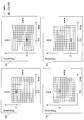
- the first pilot symbol may be CSI-RS (CSI-Reference Signal) of LTE-A shown in FIG. 6 instead of CRS.
- CSI-RS is a pilot symbol used to feed back channel conditions to a base station.
- FIG. 6 shows an example of CSI-RS.
- two resource elements for arranging CSI-RS are prepared in one subframe, and two streams are code-multiplexed and inserted. To do. Since four of them are prepared, up to 8 streams can be inserted.
- CSI-RS is inserted in the entire band in the same manner as CRS.
- the pilot symbol may not be LTE-A.
- first pilot symbol and the second pilot symbol are inserted in the same subframe, but each may be inserted in a temporally different subframe. .
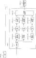
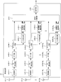
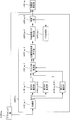
- FIG. 7 is a schematic block diagram showing the configuration of the receiving device b1 according to this embodiment.
- the receiving device b1 includes a receiving unit b101-n R , a GI removing unit b102-n R , an FFT unit (also referred to as a time frequency converting unit) b103-n R , a demapping unit b104-n R , and a path extracting unit.
- b105-n R propagation path estimation unit b106-n R , MIMO separation unit b107, and decoding unit b108.
- n R 1,2, ⁇ , a N R.
- the receiving antenna b1-n R is also shown.
- the reception unit b101-n R receives the transmission signal transmitted by the transmission device a1 via the reception antenna b1-n R.
- the receiving unit b101-n R performs frequency conversion and analog-digital (AD) conversion on the received signal.
- the GI removal unit b102-n R removes the GI from the signal input from the reception unit b101-n R, and outputs the GI to the FFT unit b103-n R.
- the FFT unit b103-n R performs time-frequency conversion on the time domain signal input from the GI removal unit b102-n R, and outputs the converted frequency domain signal to the demapping unit b 104-n R.
- the demapping unit b104-n R performs demapping based on mapping information notified in advance from the transmission device a1, and separates data and pilot symbols.
- the separated first pilot symbol is output to path extraction section b105-n R
- the second pilot symbol is output to propagation path estimation section b106-n R
- the data is output to MIMO separation section b107.
- the path extraction unit b105-n R calculates path information using the first pilot symbol input from the demapping unit b104-n R, and outputs the path information to the propagation path estimation unit b106-n R. Specific processing will be described later with reference to FIG.
- the propagation path estimation unit b106-n R uses the second pilot symbol input from the demapping unit b104-n R and the path information input from the path extraction unit b105-n R to generate the second CFR estimation value. Is output to the MIMO separation unit b107. Specific processing will be described later with reference to FIG.
- the MIMO separation unit b107 uses the U second CFR estimation values input from the propagation path estimation unit b106-n R , that is, the QR second CFR estimation values, and uses a ZF (Zero Forcing) criterion, an MMSE. (Minimum Mean Square Error) Calculates filter coefficients such as criteria and performs MIMO separation. Alternatively, separation may be performed using nonlinear processing such as MLD (Maximum Likelihood Detection) using the QR second CFR estimation values. Using these known techniques, a bit log likelihood ratio (LLR) is calculated and output to the decoding unit b108.
- ZF Zero Forcing
- MMSE Minimum Mean Square Error
- the decoding unit b108 uses, for example, the maximum likelihood decoding method (Maximum Likelihood Decoding), the maximum posterior probability (Maximum A posteriori Probability; MAP), log-MAP, Max-log using the bit LLR input from the MIMO separation unit b107.
- MAP Maximum Likelihood Decoding
- MAP maximum posterior probability
- log-MAP Max-log using the bit LLR input from the MIMO separation unit b107.
- -Decoding processing is performed using MAP, SOVA (Soft Output Viterbi Algorithm) or the like.
- FIG. 8 is a schematic block diagram showing the configuration of the path extraction unit b105-n R.
- the path extraction unit b105-n R includes a separation unit b105-n R -1, a temporary CFR (Channel Frequency Response) estimation unit b105-n R -2-n ′ T , and an FFT unit b105-n.
- R -3-n ′ T a path position extraction unit b105-n R -4-n ′ T , and a path position integration unit b105-n R -5.
- n ′ T 1, 2,..., N ′ T.
- the demultiplexing unit b105-n R ⁇ 1 demultiplexes the received signal of the resource element into which the first pilot symbol is inserted, which is input from the demapping unit b104-n R, for each stream, and divides the n ′ T-th stream. and outputs to the temporary CFR estimation unit b105-n R -2-n ' T.
- Provisional CFR estimator b105-n R- 2-n ′ T estimates the CFR of the subcarrier in which the first pilot symbol is inserted (referred to as a provisional CFR estimation value).
- the temporary CFR estimation value to output to IFFT section b105-n R -3-n ' T.
- the IFFT unit b105-n R -3-n ′ T performs frequency-time conversion on the temporary CFR estimation value input from the temporary CFR estimation unit b 105-n R -2-n ′ T , and performs a temporary channel impulse response (Channel Impulse response). Response; CIR) is converted into an estimated value.
- the temporary CIR estimation value is output to the path position extraction unit b105-n R -4-n ′ T.
- the path position extraction unit b105-n R -4-n ′ T extracts N s paths from the temporary CIR estimation values input from the IFFT unit b 105-n R -3-n ′ T in descending order of power. To do.
- the extracted path information is output to the path position integration unit b105-n R- 5.
- the value of N s may be determined at the design stage of the receiving device b1, such as 50, 60, 70, etc., or may be changed when the firmware or software of the receiving device b1 is updated at the design stage. You may do.
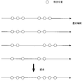
- the path position integration unit b105-n R -5 integrates N ′ T path information input from the path position extraction unit b105-n R -4-n ′ T, and sends it to the propagation path estimation unit b106-n R. Output. This operation will be described later together with the operation principle.
- FIG. 9 is a schematic block diagram showing the configuration of the propagation path estimation unit b106-n R.
- the propagation path estimator b106-n R includes a first CFR estimator b106-n R -1, a CIR estimator b106-n R -2-u, and a second CFR estimator b106-n R-.
- 3-u is included.
- u 1, 2,..., U max .
- U max is the maximum number of streams that can be received by the receiving apparatus b1.
- the first CFR estimator b106-n R ⁇ 1 uses the second pilot symbol input from the demapping unit b104-n R and uses the first pilot of the subcarrier in which the second pilot symbol is inserted. CFR is estimated by the number of multiplexed U streams. When the second pilot symbol is DMRS, the DMRS code-multiplexed with the target subcarrier may be solved. The estimated first CFR estimation value of the u-th stream is output to CIR estimation section b106-n R- 2-u.
- the CIR estimator b106-n R- 2-u receives the first CFR estimation value of the u-th stream input from the first CFR estimator b106-n R -1, and the path extractor b105-n R. The CIR estimation value is calculated using the path information. The calculated CIR estimation value is output to the second CFR estimation unit b106-n R- 3-u.
- the second CFR estimator b106-n R -3-u performs time-frequency conversion on the CIR estimated value input from the CIR estimator b106-n R- 2-u, and converts it into a CFR (second CFR). Called).
- the second CFR estimation unit b106-n R- 3-u outputs the calculated second CFR estimation value to the MIMO separation unit b107.
- the reception signal r nR (t) at time t received by the reception unit b102-n R is expressed by the following equations (1) to (3).
- T D is the maximum delay time
- h nR, nT ( ⁇ ) is the complex amplitude at the delay time ⁇ from the transmission antenna a 1 -n T to the reception antenna b 1 -n R
- s nT (t) is the transmission antenna.
- the transmission signal from a1-n T , z nR (t) is the noise at the reception antenna b1-n R , s nT, i (t) is the transmission signal from the transmission antenna a1-n T for the i-th symbol only, and N is The number of FFT points, S nT , i, n is a modulated signal from the transmission antenna a1-n T of the n-th subcarrier of the i-th symbol, TG is the guard interval length, T s is the length of the OFDM symbol section, ⁇ f Is a frequency interval between subcarriers.
- tau 0 complex amplitude h nR of ⁇ T D, nT ( ⁇ ) collectively referred to as the channel impulse response.
- modeling is performed on the assumption that the preceding wave of the transmission signal and the reception signal is synchronized, and there is no channel fluctuation within the subframe.
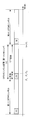
- Figure 10 shows the transmitted signal s nT from the transmitting antennas a1-n T i th symbol, the configuration of the i (t).
- the transmission signal s nT (t) is configured in such a way that these OFDM symbols are arranged in time.
- a reception signal in the digital domain is obtained by the reception unit b101-n R , the GI is removed by the GI removal unit b102-n R , and time-frequency conversion is performed by the FFT unit b103-n R.
- the received signal R nR, i, n of the n-th subcarrier in the i-th symbol obtained is expressed by the following equations (4) to (5).
- S nT , i, n are signals output from the precoding unit a105 in the transmission device a1 in FIG.
- H n the CFR matrix N R ⁇ N T is S i
- n is the transmitted signal vector of the N T ⁇ 1
- Z i is N noise vector R ⁇ 1
- X T represents a transpose of X
- the N T ⁇ U precoding matrix V is expressed by the following equation (9). Note that precoding is preferable in terms of improving transmission characteristics, but the case where precoding is not performed is also included in the present invention.
- the received signal vector R i, n can be rewritten as the following equations (10) to (13).
- H v, nR, nT, n that is a CFR after being affected by precoding may be estimated and used.
- second CFR estimated values H ′′ v, nR, nT, n which are estimated values of H v, nR, nT, n used for demodulation, are obtained, and the remaining functions of receiving apparatus b1 Will be explained.
- the operating principles of the path extraction unit b105-n R and the propagation path estimation unit b106-n R that estimate H ′′ v, nR, nT, n will be described later.
- the MIMO separation unit b107 uses the following equations (14) and (15) for the separated symbols c ′ u, i, n in the u-th stream of the i-th symbol and the n-th subcarrier. Use to calculate.
- the X H represents a complex conjugate transpose of X
- e u is the size U ⁇ 1
- the sigma 2 is the power of Z nR, i, n, c u obtained using the results of decoding, by using i, replica c '' u of n, i, n, the following equation (16) Can be estimated as follows.
- the number of subcarriers to be averaged is adjusted as appropriate. This process may be performed on a symbol that has been decoded. It should be noted that not only averaging in the subcarrier direction as in equation (16), but also averaging with respect to symbols (average with respect to i), or performing weighted averaging that forgets past results at that time. Good. Also, as c ′′ u, i, n , a soft replica created using the output result of the decoding unit b108 may be used, or a hard replica obtained by making a hard decision on the demodulation result may be used.
- the decoding result but the demodulation result c ′′ u, i, n may be used as they are, or a hard replica obtained by hard decision thereof may be used. Further, in the case of corresponding to the pilot symbol, the pilot symbol may be used as it is.
- the MIMO separation unit b107 calculates a bit log likelihood ratio from the post-MIMO separation symbol c ′ u, i, n in Expression (14).
- An equivalent amplitude gain is used for this calculation process.
- the bit log likelihood ratio ⁇ is equal to the equivalent amplitude gain ⁇ u, i, n in the u-th stream of the i-th symbol n-th subcarrier expressed by the following equation (17): It represents with following Formula (18) and (19).
- the equations (18) and (19) are respectively expressed by bit log likelihood ratios ⁇ (1) of the bits b u, i, n, 0 of the first bit and bits b u, i, n, 1 of the second bit.
- the first CFR estimation unit b106-n R ⁇ 1 calculates the first CFR estimation value using the DMRS inserted as shown in FIG.
- DMRSs of the first, second, fifth, and seventh streams are inserted into the pattern 501 in FIG. 5, and DMRSs of the third, fourth, sixth, and eighth streams are inserted into the pattern 502.
- DMRSs of the first, second, fifth, and seventh streams are inserted will be described with reference to 501 in FIG.
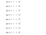
- DMRS code multiplexing is performed using four resource elements of the same subcarrier. If the code vector of the u-th stream of size 4 ⁇ 1 is d u , the signal of each resource element of the subcarrier into which DMRS 501 in FIG. 5 is inserted is expressed by the following equation (20).
- cp , u, n is a pilot symbol in the n-th subcarrier of the u-th stream, and n is limited to 1, 5, and 11 with reference to 501 in FIG. No signal is transmitted from the first, second, fifth and seventh streams to the corresponding resource element. Further, du is represented in FIG.
- the received signal received receiving antenna b1-n R is the resource element represented by the formula (20), with reference to equation (10), the following equation (21).
- the first CFR estimation value H 'v, nR, u, n can be obtained by multiplying the code vector d u to the received signal vector of the formula (21), the following equation (22), (23 ).
- n 1 ,..., N P are pilot subcarriers, and P is the number of pilot subcarriers.
- P is the number of pilot subcarriers.
- F is a P ⁇ L discrete Fourier transform matrix
- L is an assumed maximum discrete delay time. L only needs to satisfy L> D, and a larger value may be set. For example, it may be set GI points N g, it may be set to a value greater than that.
- the CIR estimation vector hv, nR, u is expressed by the following equations (29) and (30) using MMSE.
- E [X] represents the ensemble average of X
- the diagonal elements of Cv , h represent PDP.
- C v, h is obtained by a path extraction unit b105-n R described later.
- the second CFR estimator b106-n R- 3-u performs time-frequency conversion on the CIR estimated value input from the CIR estimator b106-n R- 3-u to obtain the second CFR estimated value H ′.
- 'Estimate v, nR, u, n This can be obtained by the following equations (31) and (32).
- the CFR estimated value H ′′ v, nR, u, n is output.
- the operation of the path extraction unit b105-n R will be described with reference to FIG. Separating section b105-n R -1, the first pilot symbol to separate the received signals of the resource elements are arranged at a first n 't stream.
- the CRS of the first stream is the gray resource element in 401, and in the case of the second stream, the gray resource element in 402 is extracted, and the temporary CFR estimator b105-n R -2-n 'Output to t .
- cn′T, i, n is CRS, and is valid only when the symbol number i and the subcarrier number are in the gray position in FIG.
- a temporary CFR estimation value is calculated using Equation (33) at each position, and the two are averaged. Use things in the future.
- the temporary CFR estimation values H ′ nR, n′T, n obtained by the equation (33) are subjected to frequency time conversion such as IFFT. Further, only paths with discrete delay times 0 to L ⁇ 1 are extracted.
- the path position integration unit b105-nR-5 integrates the input N ′ T path position information. Specifically, if the discrete delay time d is extracted in any of the 1 to N ′ T streams, the position d is extracted even if it is not extracted in other streams. . For example, they are integrated as shown in FIG.
- ⁇ is a hyper parameter, and a fixed value such as 0.5 or 0.25 may be assigned. Every time the equation (29) is calculated, a known technique such as an EM (Expectation Maximization) algorithm is used. You may optimize.
- EM Engineering Maximization
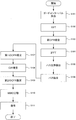
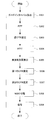
- FIG. 15 is a flowchart showing the operation of the receiving apparatus according to this embodiment. The operation shown in this figure is processing after the receiving unit b101-n R in FIG. 7 outputs the received signal to the GI removing unit b102-n R.
- Step S101 The GI removal unit b102-n R removes the GI from the received signal. Then, it progresses to step S102.
- Step S102 The FFT unit b103-n R performs time frequency conversion on the signal obtained in step S101.
- the demapping unit b104-n R separates the received signal of the resource element to which the data, the first pilot symbol, and the second pilot symbol are transmitted from the obtained frequency domain signal.
- the received signal of the resource element to which data is transmitted is transmitted to the MIMO separation unit b107, and the received signal of the resource element to which the first pilot symbol is transmitted is transmitted to the path extraction unit b105-n R.
- the reception signal of the resource element is output to the propagation path estimation unit b106-n R.
- the separation unit b105-n R ⁇ 1 of the path extraction unit b105-n R separates the reception signal of the resource element, to which the first pilot symbol is transmitted, for each transmission antenna. Thereafter, the process proceeds to step S103.
- Step S103 The provisional CFR estimation unit b105-n R- 2-n ′ T calculates a provisional CFR estimation value in the resource element to which the first pilot symbol is transmitted for each transmission antenna. Thereafter, the process proceeds to step S104.
- Step S104 The IFFT unit b105-n R- 3-n ′ T performs frequency-time conversion on the temporary CFR estimated value obtained in Step S103, and converts it into a temporary CIR estimated value. Thereafter, the process proceeds to step S105.
- Step S105 The path position extraction unit b105-n R -4-n ′ T extracts a predetermined number of paths in descending order of power from the temporary CIR estimation values obtained in Step S104. Thereafter, the process proceeds to step S106.
- Step S106 The path position integration unit b105-n R -5 integrates the path position for each transmission antenna obtained in step S105. Thereafter, the process proceeds to step S107.
- Step S107 The first CFR estimator b106-n R ⁇ 1 of the propagation path estimator b106-n R (FIG. 9) receives the received signal of the resource element to which the second pilot symbol obtained in Step S102 is transmitted. Is used to calculate the first CFR estimate. Thereafter, the process proceeds to step S108.
- Step S108 The CIR estimation unit b106-n R- 2-u calculates a CIR estimation value using the path position information obtained in Step S106 and the first CFR estimation value obtained in Step S107. Thereafter, the process proceeds to step S109.
- Step S109 The second CFR estimator b106-n R -3-u performs time-frequency conversion on the CIR estimated value obtained in step S108, and converts it to a second CFR estimated value. Then, it progresses to step S110.
- Step S110 The MIMO separation unit b107 performs MIMO separation using the received signal of the resource element to which the data obtained in step S102 is transmitted and the second CFR estimation value obtained in step S109, and performs coding bit LLR is calculated. Thereafter, the process proceeds to step S111.
- Step S111 The decoding unit b108 performs decoding using the LLR of the encoded bit obtained in step S110. Thereafter, the receiving device b1 ends the operation.
- the PDP setting unit operates as a path extraction unit, and extracts a path effective for estimation using the first pilot symbol.
- the propagation path estimation unit calculates a first CFR estimation value using the second pilot symbol, and calculates a CIR estimation value using the path position information extracted by the path extraction unit and the first CFR estimation value. And then converted to a second CFR estimate.
- the receiving apparatus b1 includes N R path extraction units b105-n R as shown in FIG. 7, but the number may be one.
- the path information extracted by one path extraction unit can be shared by all of the propagation path estimation units b106-n R.
- the present embodiment is applied to a receiving apparatus that performs interference cancellation processing using a CIR estimation value.
- a form of propagation path estimation technique may be applied.
- the transmission device a1 maps and transmits the first pilot symbol and the second pilot symbol in the frequency domain
- the reception device b1 uses the first pilot symbol to obtain the provisional CIR estimation.
- a predetermined number of paths are extracted in descending order of power.
- a second CFR estimation value is calculated using the second pilot symbol and the obtained path information.
- the propagation path adaptability of a path is calculated one by one and the paths are extracted in descending order of the propagation path adaptability.
- the configuration of the transmission device a2 according to the present embodiment is the same as that of the transmission device a1 according to the first embodiment, description thereof is omitted.
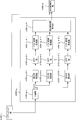
- FIG. 16 is a schematic block diagram showing the configuration of the receiving device b2 according to this embodiment.
- the path extraction unit b205-n R is different.
- other functions reception unit b101-n R , GI removal unit b102-n R , FFT unit b103-n R , demapping unit b104-n R , propagation path estimation unit b106-n R , MIMO separation unit b107, The operation of the decoding unit b108) is the same as that of the receiving device b1.
- the description of the same operation as that of the first embodiment is omitted.
- FIG. 17 is a schematic block diagram showing the configuration of the path extraction unit b205-n R.
- a path extraction unit b 205-n R in FIG. 17 is compared with the path extraction section b105-n R in FIG. 8, IFFT unit b105-n R -3-n ' T, the path position extracting section b105-n R -4 ⁇ n ′ T , path location integration unit b105-n R ⁇ 5 is not provided, test CIR estimation unit b205-n R ⁇ 3, propagation path fitness calculation unit b205-n R ⁇ 4, unnecessary candidate path removal unit b205 ⁇ n R ⁇ 5, determination unit b205-n R ⁇ 6, and path determination unit b205-n R ⁇ 7.
- the path extraction unit b105-n R includes a primary storage location (not shown for easy viewing of the drawing), and includes “selected path (selected_path)”, “candidate path (candidate_path)”, “previous one”. “Channel propagation match (channel_match_prev)” and “Channel propagation match (channel_match)” are stored.
- the test CIR estimator b205-n R -3 calculates the CIR estimated value when one element of the “candidate_path” is added to the path stored in the “selected path (selected_path)”, It is calculated using the temporary CFR estimation value input from the temporary CFR estimation unit b105-n R -2-n ' T. That is, CIR estimation is performed for the number of elements of “candidate_path”.
- the calculated test CIR estimated value and the provisional CFR estimated value used for the calculation are output to the propagation path adaptability calculating unit b205-n R -4.
- the propagation path fitness calculation unit b205-n R -4 receives the temporary CFR estimation value input from the test CIR estimation unit b205-n R -3 and the test CIR estimation value for the number of elements of “candidate_path”. And the propagation path matching degree in each case is calculated and stored in “propagation path matching degree (channel_match)”. Details of the calculation of the propagation path suitability will be described later.
- the propagation path fitness calculation unit b205-n R -4 outputs the calculated propagation path fitness to the unnecessary candidate path removal unit b205-n R -5.
- the unnecessary candidate path removal unit b205-n R -5 compares the input propagation path matching degree with the “preceding channel matching degree (channel_match_prev)”, and if the former is smaller than the latter, the small propagation The channel matching level is deleted from the content of “propagation channel matching level (channel_match)”.
- the unnecessary candidate path removal unit b205-n R -5 also deletes the element of “candidate_path” corresponding to the small propagation path fitness. Thereafter, the “candidate_path” after the deletion is output to the determination unit b205-n R- 6.
- the determination unit b205-n R- 6 determines whether or not to continue the path extraction process. If the number of elements of the “candidate_path” input from the unnecessary candidate path removing unit b205-n R- 5 is smaller than the predetermined number, the path extraction process is terminated, and “selected path (selected_path ) "to output to channel estimation section b106-n R a path number stored and path numbers stored in the" candidate path (Candidate_path) "as the path information. Otherwise, “candidate_path” is output to the path determination unit b205-n R ⁇ 7. Note that the predetermined number used here may be determined at the design stage of the receiving device b2, or may be updated when the firmware or software of the receiving device b2 is updated. In particular, when the predetermined number is 1, path extraction is performed until there is no “candidate_path”.
- the path determination unit b205-n R -7 selects the maximum one of the propagation path matching degrees stored in the “propagation path matching degree (channel_match)”.
- the “candidate path (candidate_path)” corresponding to the selected propagation path fitness is determined as a new extraction path and stored in the “selected path (selected_path)”. Further, the selected propagation path matching degree is stored in “previous propagation path matching degree (channel_match_prev)”.
- the “selected path (selected_path)” of the primary storage location is emptied, the “candidate_path” of the primary storage location is set to 0 to L, and the “adjacent propagation path suitability” of the primary storage location Let (channel_match_prev) "be a small value (eg, negative infinity). Note that L is the assumed maximum delay time as in the first embodiment.
- Test CIR estimation vector h q, nR, n from transmitting antenna n ′ T when one path of “candidate_path” is added to the path stored in “selected path (selected_path)” 'T is estimated.
- the MMSE method of Expression (29) may be used.
- the CFR estimation vector in the equation (29) is changed to one having the temporary CFR estimation value obtained in the equation (33) as an element (H nR, n′T ), and the discrete Fourier in the equation (29) is used.
- the transformation matrix F changes the definition in equation (25). Specifically, n 1 , n 2 ,..., N P in the equation (25) are changed to subcarrier numbers obtained by estimating the temporary CFR in the equation (33).
- the first term of the equation (36) is an evaluation value of an error between the temporary CFR estimated value and the CIR estimated value calculated at the time of the q pass number, and specifically uses cross-correlation.
- the second term represents a penalty for increasing the number of passes.
- x is a parameter that determines the magnitude of the penalty.
- a natural logarithm value of 2 or the number of subcarriers in which pilot symbols are arranged may be used.
- the case 2 is AIC (Akaike Information Criteria)
- BIC Bayesian Information Criteria
- FIG. 18 is a flowchart showing the operation of the receiving apparatus according to this embodiment. The operation shown in this figure is processing after the receiving unit b101-n R in FIG. 16 outputs the received signal to the GI removing unit b102-n R.
- Step S201 The GI removal unit b102-n R removes the GI from the received signal. Thereafter, the process proceeds to step S202.
- Step S202 The FFT unit b103-n R performs time-frequency conversion on the signal obtained in Step S201.
- the demapping unit b104-n R separates the received signal of the resource element to which the data, the first pilot symbol, and the second pilot symbol are transmitted from the obtained frequency domain signal.
- the received signal of the resource element to which data is transmitted is transmitted to the MIMO separation unit b107, and the received signal of the resource element to which the first pilot symbol is transmitted is transmitted to the path extraction unit b205-n R.
- the reception signal of the resource element is output to the propagation path estimation unit b106-n R.
- the separation unit b105-n R ⁇ 1 of the path extraction unit b205-n R separates the received signal of the resource element to which the first pilot symbol is transmitted for each transmission antenna. Then, it progresses to step S203.
- Step S203 The provisional CFR estimation unit b105-n R- 2-n ′ T calculates a provisional CFR estimation value in the resource element to which the first pilot symbol is transmitted for each transmission antenna. Thereafter, the process proceeds to step S204.
- Step S204 The test CIR estimation unit b205-n R -3 adds the respective elements of “candidate_path” to the path number stored in the “selected path (selected_path)”. Calculate an estimate. Thereafter, the process proceeds to step S205.
- Step S205 The propagation path matching degree calculation unit b205-n R -4 uses the temporary CFR estimated value obtained in step S203 for each of the test CIR estimated values obtained in step S204 to set the “propagation degree (channel_match ) ”Is calculated. Thereafter, the process proceeds to step S206.
- Step S206 The unnecessary candidate path removal unit b205-n R -5 is an element that is less than the “preceding channel match (channel_match_prev)” of the “channel match (channel_match)” obtained in step S205. Is selected and the element of the candidate path corresponding to the element is deleted. Thereafter, the process proceeds to step S207.
- Step S207 If the number of elements of the “candidate_path” is less than the predetermined number as a result of Step S206, the determination unit b205-n R- 6 is stored in the “selected path (selected_path)”. the path number and the path number stored in the "candidate path (candidate_path)" who is to output to channel estimation section b106-n R as the path information. Thereafter, the process proceeds to step S209. If the condition is not met, the process proceeds to step S208.
- Step S208 The path determination unit b205-n R -7 selects the “candidate_path” element corresponding to the largest one among the “propagation channel match (channel_match)” elements, To the selected path (selected_path) ". In other words, the path number that has been selected is deleted from the "candidate path (candidate_path)". Thereafter, the process returns to step S204.
- Step S209 The first CFR estimator b106-n R ⁇ 1 of the propagation path estimator b106-nR uses the received signal of the resource element to which the second pilot symbol obtained in Step S202 is transmitted. 1 CFR estimate is calculated. Thereafter, the process proceeds to step S210.
- Step S210 The CIR estimating unit b106-n R- 2-u calculates a CIR estimated value using the path position information obtained in Step S207 and the first CFR estimated value obtained in Step S209. Then, it progresses to step S211.
- Step S211 The second CFR estimator b106-n R -3-u performs time-frequency conversion on the CIR estimated value obtained in Step S210 and converts it to a second CFR estimated value. Thereafter, the process proceeds to step S212.
- Step S212 The MIMO separation unit b107 performs MIMO separation using the received signal of the resource element to which the data obtained in step S202 is transmitted and the second CFR estimation value obtained in step S211 and LLR is calculated. Thereafter, the process proceeds to step S213.
- Step S213 The decoding unit b108 performs decoding using the LLR of the coded bit obtained in step S212. Thereafter, the receiving device b2 ends the operation.
- the path extraction unit can prevent unnecessary paths from being extracted by extracting the paths that improve the channel matching degree one by one. For this reason, the channel estimation accuracy is improved, and the accuracy of MIMO separation can be improved by using the channel estimation value with improved accuracy.
- the path determination unit b205-n R -7 determines the number of paths determined by one iteration process, but may be larger than that. For example, in the case of 3, Then, three paths are extracted in descending order of propagation path adaptability. In this case, the channel matching degree when three paths are added is calculated, and the channel matching degree is stored in the “preceding channel matching degree (channel_match_prev)”.
- the receiving device b2 includes N R path extraction units b205-n R as illustrated in FIG. 16 has been described.
- the number may be one.
- the path information extracted by one path extraction unit is shared by all of the propagation path estimation units b106-n R.
- the transmission device a1 maps and transmits the first pilot symbol and the second pilot symbol in the frequency domain
- the reception device b1 uses the first pilot symbol to obtain the provisional CIR estimation.
- a predetermined number of paths are extracted in descending order of power.
- to calculate a second CFR estimation value using the path information obtained with the second pilot symbol a case will be described in which a continuous PDP is set from the obtained path information and the second CFR estimated value is calculated using a frequency correlation that can be calculated from the PDP.
- the configuration of the transmission device a3 according to the present embodiment is the same as that of the transmission device a1 according to the first embodiment, description thereof is omitted.
- Figure 19 is a schematic block diagram showing the configuration of a receiving apparatus b3 according to the present embodiment. 19 is compared with the receiving device b1 in FIG. 7, the path setting unit b305-n R is provided instead of the path extracting unit b105-n R , and the propagation path estimating unit b306-n R is different. However, other functions (reception unit b101-n R , GI removal unit b102-n R , FFT unit b103-n R , demapping unit b104-n R , MIMO separation unit b107, decoding unit b108) It is the same as the receiving device b1. The description of the same operation as that of the first embodiment is omitted.
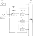
- FIG. 20 is a schematic block diagram showing the configuration of the section setting unit b305-n R.
- a section setting unit B 305-n R in FIG. 20 is compared with the path extraction section b105-n R 8, the path position extracting section b105-n R -4-n ' T and the path integration unit b105-n R - 5 and a path / section conversion unit b305-n R -4-n ′ T and a frequency correlation calculation unit b305-n R -5.
- the operations of other functions (separation unit b105-n R -1, provisional CFR estimation unit b105-n R -2-n ' T , IFFT unit b105-nR-3-n' T ) Is the same.
- the description of the same operation as that of the first embodiment is omitted.
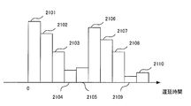
- the path / section conversion unit b305-n R- 4-n ′ T converts the temporary CIR estimation value input from the IFFT unit b105-nR-3-n ′ T into a continuous value PDP. Specifically, when the provisional CIR estimates were as shown in FIG. 13, it converts as shown in FIG. 21. For example, the section 2101 has been converted from the path 1301, and if the power of the path 1301 is a, the height of the section 2101 is a / ⁇ t, and the horizontal width of the section 2101 is ⁇ t . The PDP thus obtained, and outputs it to the frequency correlation calculating unit b305-n R -5.
- the frequency correlation calculation unit b305-n R -5 first averages the PDPs input from the path / conversion unit b305-n R -4-n ′ T. Then, to calculate the frequency correlation from averaged PDP, and outputs the propagation channel estimation unit b306-n R. Details of the frequency correlation calculation method will be described later.
- Figure 22 is a schematic block diagram showing the configuration of a channel estimation unit b306-n R.
- the second CFR estimation value is calculated from the frequency correlation value input from, and output to the MIMO separation unit b107.
- the second CFR estimation vector H ′′ v, nR, u calculated by the equation (31) is expressed by the following equations (37) to (39).
- H ′ v, nR, u is the first CFR estimation value as in the first embodiment
- ⁇ n, m is the frequency correlation between subcarriers n and m. If the PDP with the horizontal axis as the delay time ⁇ is C ( ⁇ ), ⁇ n, m is expressed by the following equation (40).
- ⁇ n, m is input from the section setting unit.
- FIG. 23 is a flowchart showing the operation of the receiving apparatus according to this embodiment. The operation shown in this figure is processing after the reception unit b101-n R in FIG. 19 outputs the reception signal to the GI removal unit b102-n R.
- Step S301 GI removal unit b 102-n R removes GI from the received signal. Thereafter, the process proceeds to step S302.
- Step S302 FFT unit b103-n R performs a time-frequency conversion on the signal obtained at step S301.
- the demapping unit b104-n R separates the received signal of the resource element to which data, the first pilot symbol, and the second pilot symbol are transmitted from the obtained frequency domain signal.
- the received signal of the resource element to which data is transmitted is transmitted to the MIMO separation unit b107, the received signal of the resource element to which the first pilot symbol is transmitted is transmitted to the section setting unit b305-n R , and the second pilot symbol is transmitted.
- the reception signal of the resource element is output to the propagation path estimation unit b306-n R.
- the separation unit b105-n R ⁇ 1 of the section setting unit b305-nR separates the reception signal of the resource element, to which the first pilot symbol is transmitted, for each transmission antenna. Thereafter, the process proceeds to step S303.
- Step S303 The provisional CFR estimation unit b105-n R- 2-n ′ T calculates a provisional CFR estimation value in the resource element to which the first pilot symbol is transmitted for each transmission antenna. Thereafter, the process proceeds to step S304.
- Step S304 The IFFT unit b105-n R -3-n ′ T performs frequency-time conversion on the temporary CFR estimated value obtained in Step S303, and converts it into a temporary CIR estimated value. Thereafter, the process proceeds to step S305.
- Step S305 The frequency correlation calculation unit b305-n R -5 converts the temporary CIR estimation value obtained in step S304 into a PDP, and calculates a frequency correlation from the converted PDP. Thereafter, the process proceeds to step S306.
- Step S306 The first CFR estimator b106-n R ⁇ 1 of the propagation path estimator b306-n R uses the received signal of the resource element to which the second pilot symbol obtained in Step S302 is transmitted, A first CFR estimate is calculated. Thereafter, the process proceeds to step S307.
- Step S307 The second CFR estimator b306-n R- 2-u uses the frequency correlation obtained in Step S305 and the first CFR estimated value obtained in Step S306 to generate the second CFR estimated value. Is calculated. Thereafter, the process proceeds to step S308.
- Step S308 The MIMO separation unit b107 performs MIMO separation using the received signal of the resource element to which the data obtained in step S302 is transmitted and the second CFR estimation value obtained in step S307, LLR is calculated. Thereafter, the process proceeds to step S309.
- Step S309 The decoding unit b108 performs decoding using the LLR of the encoded bit obtained in step S308. Thereafter, the receiving device b3 ends the operation.
- the PDP setting unit calculates the temporary CIR estimated value using the first pilot symbol, converts the calculated temporary CIR estimated value into the PDP, and converts the calculated PDP from the frequency correlation. Is calculated. Also, a first CFR estimation value is calculated using the second pilot symbol. A second CFR estimated value is calculated using these frequency correlations and the first CFR estimated value.
- the path extraction in the first embodiment or the second embodiment may be performed to reduce the number of paths and then convert to PDP.
- the present invention is not limited to MIMO. If it is not MIMO, the estimated second CFR estimation value is used for propagation path compensation.
- the path extraction unit b105-n R and the propagation path estimation unit b106-n R may be realized by a computer.
- the program for realizing the control function may be recorded on a computer-readable recording medium, and the program recorded on the recording medium may be read by a computer system and executed.
- the “computer system” here is a computer system built in the transmission device a1 or the reception devices b1 to b3, and includes hardware such as an OS and peripheral devices.
- the “computer-readable recording medium” refers to a storage device such as a portable medium such as a flexible disk, a magneto-optical disk, a ROM, and a CD-ROM, and a hard disk built in the computer system.
- the “computer-readable recording medium” is a medium that dynamically holds a program for a short time, such as a communication line when transmitting a program via a network such as the Internet or a communication line such as a telephone line,
- a volatile memory inside a computer system serving as a server or a client may be included and a program that holds a program for a certain period of time.
- the program may be a program for realizing a part of the functions described above, and may be a program capable of realizing the functions described above in combination with a program already recorded in a computer system.
- part or all of the transmission device a1 and the reception devices b1 to b3 in the above-described embodiment may be realized as an integrated circuit such as an LSI (Large Scale Integration).
- LSI Large Scale Integration
- Each functional block of the transmission device a1 and the reception devices b1 to b3 may be individually made into a processor, or a part or all of them may be integrated into a processor.
- the method of circuit integration is not limited to LSI, and may be realized by a dedicated circuit or a general-purpose processor. Further, in the case where an integrated circuit technology that replaces LSI appears due to progress in semiconductor technology, an integrated circuit based on the technology may be used.
Abstract
A GI removing unit (b102-nR) removes a GI from a received signal. An FFT unit (b103-nR) performs time frequency conversion on a signal received in step S101. A demapping unit (b104-nR) separates, from the signal of a frequency region that can be obtained, the received signal of resource elements for which data, a first pilot symbol and a second pilot symbol are transmitted. A pass extraction unit (b105-nR) uses the first pilot symbol to extract a pass valid for estimation. A propagation path estimation unit (b106-nR ) calculates a first CFR estimation value using the second pilot symbol, calculates a CIR estimation value using pass position information extracted by the pass extraction unit and the first CFR estimation value, and thereafter converts the calculation results to a second CFR estimation value.
Description
本発明は、LTEやLTE-Aなどの無線通信システムにおいて、復調用の伝搬路推定を行う受信装置、受信方法および受信プログラムに関する。
The present invention relates to a receiving apparatus, a receiving method, and a receiving program for estimating a propagation path for demodulation in a wireless communication system such as LTE or LTE-A.
無線通信においては、特に広帯域伝送の場合、先行して受信するパスに加え、建物や山などの障害物からの反射を経由する等して遅延して到来するパスが存在し、このように複数のパスが到来する環境をマルチパス環境という。近年、このようなマルチパス環境で高速・高信頼伝送を実現する手法としてOFDM(Orthogonal Frequency Division Multiplexing;直交周波数分割多重)が注目されており、LTE(Long Term Evolution)やLTE-A(LTE-Advanced)等の次世代移動通信システム、無線LAN、放送等の様々な分野で採用されている。受信装置がOFDM信号を復調する場合には、チャネル推定を行って、サブキャリア毎に伝搬路の周波数応答(Channel Frequency Response;CFR)を算出する必要がある。これを実現するため、受信装置がその波形(あるいは、その信号系列)を予め記憶するパイロットシンボルを、送信装置から受信装置へ送信する方法がある。そのパイロットシンボルを用いて高精度なチャネル推定を行うには、高精度な遅延プロファイル(Power Delay Profile;PDP)が必要となる。
In wireless communication, in particular, in the case of broadband transmission, in addition to the path received in advance, there are paths that arrive after a delay, such as through reflections from obstacles such as buildings and mountains. An environment in which the path of arriving is called a multipath environment. In recent years, OFDM (Orthogonal Frequency Division Multiplexing) has attracted attention as a method for realizing high-speed and highly reliable transmission in such a multipath environment. LTE (Long Termination Evolution) and LTE-A (LTE-A) Advanced) and the like, and is employed in various fields such as wireless LAN and broadcasting. When a receiving apparatus demodulates an OFDM signal, it is necessary to perform channel estimation and calculate a channel frequency response (CFR) for each subcarrier. In order to realize this, there is a method in which the receiving apparatus transmits pilot symbols in which the waveform (or the signal sequence) is stored in advance from the transmitting apparatus to the receiving apparatus. In order to perform highly accurate channel estimation using the pilot symbols, a highly accurate delay profile (Power Delay Profile (PDP)) is required.
特許文献1には、チャネルインパルス応答を推定する方法が記載されている。その方法は、パス抽出と、その抽出されたパス情報を用いたチャネルインパルス応答推定の二段階の処理から成る。OFDMにこの技術を用いる場合、推定されたチャネルインパルス応答に時間周波数変換を施して周波数応答に変換してから用いる。
Patent Document 1 describes a method for estimating a channel impulse response. The method includes a two-stage process of path extraction and channel impulse response estimation using the extracted path information. When this technique is used for OFDM, the estimated channel impulse response is subjected to time-frequency conversion to be converted into a frequency response before use.
しかしながら、LTE-Aでは復調用の伝搬路推定を行うための参照信号として、ユーザ固有の復調用参照信号(Demodulation Reference Signal;DMRS)を用いており、ユーザの使用する帯域にしか参照信号が存在しないため、PDPの推定精度が低下し、結果として伝搬路推定精度も低下するという問題がある。
However, LTE-A uses a user-specific demodulation reference signal (Demodulation Reference Signal: DMRS) as a reference signal for estimating a propagation path for demodulation, and the reference signal exists only in the band used by the user. Therefore, there is a problem that the PDP estimation accuracy is lowered, and as a result, the propagation channel estimation accuracy is also lowered.
本発明は、斯かる実情に鑑み、無線通信における伝搬路推定精度を大幅に改善することができる受信装置、受信方法および受信プログラムを提供しようとするものである。
In view of such circumstances, the present invention intends to provide a receiving apparatus, a receiving method, and a receiving program capable of greatly improving the propagation path estimation accuracy in wireless communication.
本発明は、復調に用いるパイロットシンボルである第2のパイロットシンボルと、前記第2のパイロットシンボルと異なるパイロットシンボルである第1のパイロットシンボルとを受信し、前記第1のパイロットシンボルを用いて電力遅延プロファイルを得る電力遅延プロファイル設定部と、前記電力遅延プロファイルと前記第2のパイロットシンボルとを用いて前記伝搬路推定を行う伝搬路推定部と、を備えることを特徴とする受信装置である。
The present invention receives a second pilot symbol which is a pilot symbol used for demodulation and a first pilot symbol which is a pilot symbol different from the second pilot symbol, and uses the first pilot symbol to power. A receiving apparatus comprising: a power delay profile setting unit that obtains a delay profile; and a propagation path estimation unit that performs the propagation path estimation using the power delay profile and the second pilot symbol.
本発明の受信装置において、前記第1のパイロットシンボルと前記第2のパイロットシンボルは異なるリソースに配置されていることを特徴とする。
In the receiving apparatus of the present invention, the first pilot symbol and the second pilot symbol are arranged in different resources.
また、本発明の受信装置において、前記第1のパイロットシンボルと前記第2のパイロットシンボルは、空間方向の多重方法が異なることを特徴とする。
In the receiving apparatus of the present invention, the first pilot symbol and the second pilot symbol have different spatial multiplexing methods.
また、本発明の受信装置において、前記第1のパイロットシンボルと前記第2のパイロットシンボルは、配置される帯域幅が異なることを特徴とする。
In the receiving apparatus of the present invention, the first pilot symbol and the second pilot symbol have different bandwidths.
また、本発明の受信装置において、前記第1のパイロットシンボルよりも前記第2のパイロットシンボルの方が配置される帯域幅が狭いことを特徴とする。
Further, the receiving apparatus of the present invention is characterized in that a bandwidth in which the second pilot symbol is arranged is narrower than the first pilot symbol.
また、本発明の受信装置において、前記第2のパイロットシンボルにデータ信号と同じプリコーディングがかかっていることを特徴とする。
In the receiving apparatus of the present invention, the second pilot symbol is subjected to the same precoding as that of the data signal.
また、本発明の受信装置において、前記電力遅延プロファイル設定部は、有効なパスを抽出してパス情報を生成するパス抽出部として動作し、
前記伝搬路推定部は、前記第2のパイロットシンボルを用いて、前記第2のパイロットシンボルが送信されるサブキャリアにおける周波数応答である第1の周波数応答を推定する第1の周波数応答推定部と、前記パス情報と前記第1の周波数応答を用いて、チャネルインパルス応答を推定するチャネルインパルス応答推定部と、を備えることを特徴とする。 Further, in the receiving device of the present invention, the power delay profile setting unit operates as a path extraction unit that extracts a valid path and generates path information,
The channel estimation unit uses the second pilot symbol to estimate a first frequency response that is a frequency response in a subcarrier in which the second pilot symbol is transmitted; A channel impulse response estimation unit that estimates a channel impulse response using the path information and the first frequency response.
また、本発明の受信装置において、前記パス抽出部は、第1のパイロットシンボルを用いて、電力遅延プロファイル測定用の周波数応答である仮周波数応答を推定する仮周波数応答推定部と、前記仮周波数応答を仮チャネルインパルス応答に変換する周波数時間変換部と、前記仮チャネルインパルス応答のうち、電力の高い順に所定の数のパスを抽出するパス位置抽出部と、を備えることを特徴とする。
In the receiver of the present invention, the path extraction unit uses a first pilot symbol to estimate a temporary frequency response that is a frequency response for power delay profile measurement, and the temporary frequency A frequency time conversion unit that converts a response into a temporary channel impulse response, and a path position extraction unit that extracts a predetermined number of paths from the temporary channel impulse response in descending order of power.
また、本発明の受信装置において、前記パス抽出部は、選択したパスに候補パスを追加してテストチャネルインパルス応答を推定し、前記テストチャネルインパルス応答の伝搬路適合度を算出し、前記候補パスのうち、追加前の伝搬路適合度を下回るものを削除し、削除されなかった前記伝搬路適合度のうち、大きい順に所定の数のものを選択し、それらに対応する候補パスを新たな選択パスとして選択する一連の処理を、候補パスの個数が所定の数を下回るまで繰り返す、ことを特徴とする。
Further, in the receiving device of the present invention, the path extraction unit adds a candidate path to the selected path to estimate a test channel impulse response, calculates a propagation path fitness of the test channel impulse response, and the candidate path Among them, the ones that are lower than the channel compatibility before the addition are deleted, and a predetermined number of the channel adaptations that are not deleted are selected in descending order, and candidate paths corresponding to them are newly selected. A series of processes selected as paths are repeated until the number of candidate paths falls below a predetermined number.
また、本発明の受信装置において、前記パス抽出部は、前記伝搬路適合度として、前記仮周波数応答と前記候補パスを追加した場合の伝搬路推定値の誤差の評価値と、抽出したパス数が多くなることへのペナルティとの和を用いる、ことを特徴とする。
Further, in the receiving apparatus of the present invention, the path extraction unit, as the propagation path adaptability, evaluates an error evaluation value of a propagation path estimated value when the provisional frequency response and the candidate path are added, and the number of extracted paths. It is characterized by using the sum of the penalty for increasing.
また、本発明の受信装置において、前記伝搬路推定部は、前記チャネルインパルス応答推定部が出力するチャネルインパルス応答に時間周波数変換を行い、復調用の周波数応答である第2の周波数応答に変換する、ことを特徴とする。
In the receiving apparatus of the present invention, the propagation path estimation unit performs time-frequency conversion on the channel impulse response output from the channel impulse response estimation unit, and converts the channel impulse response into a second frequency response that is a frequency response for demodulation. It is characterized by that.
また、本発明の受信装置において、前記電力遅延プロファイル設定部は、前記仮周波数応答推定部と、前記周波数時間変換部と、前記周波数時間変換部が出力する前記仮チャネルインパルス応答の電力を算出し、その電力を電力遅延プロファイルに変換し、周波数相関を算出するパス・区間変換部を備える区間抽出部として動作し、
前記伝搬路推定部は、前記第1の周波数応答と、前記周波数相関を用いて、復調用の周波数応答である第2の周波数応答を算出する、ことを特徴とする。 In the receiver of the present invention, the power delay profile setting unit calculates power of the temporary channel impulse response output from the temporary frequency response estimation unit, the frequency time conversion unit, and the frequency time conversion unit. , The power is converted into a power delay profile, and operates as a section extraction unit including a path / section conversion unit that calculates a frequency correlation,
The propagation path estimation unit calculates a second frequency response, which is a frequency response for demodulation, using the first frequency response and the frequency correlation.
また、本発明は、復調に用いるパイロットシンボルである第2のパイロットシンボルと、前記第2のパイロットシンボルと異なるパイロットシンボルである第1のパイロットシンボルとを受信し、前記第1のパイロットシンボルを用いて電力遅延プロファイルを得る電力遅延プロファイル設定過程と、前記電力遅延プロファイルと前記第2のパイロットシンボルとを用いて前記伝搬路推定を行う伝搬路推定過程と、を備えることを特徴とする受信方法である。
Further, the present invention receives a second pilot symbol that is a pilot symbol used for demodulation and a first pilot symbol that is a pilot symbol different from the second pilot symbol, and uses the first pilot symbol. A power delay profile setting step for obtaining a power delay profile and a channel estimation step for performing the channel estimation using the power delay profile and the second pilot symbol. is there.
また、本発明は、前記受信方法をコンピュータに実行させるための受信プログラムである。
Further, the present invention is a receiving program for causing a computer to execute the receiving method.
この発明によれば、伝搬路推定精度を大幅に改善することができ、精度の向上した伝搬路推定値を用いることで、MIMO分離の精度を改善することができる。
According to the present invention, the propagation path estimation accuracy can be greatly improved, and the accuracy of MIMO separation can be improved by using the propagation path estimation value with improved accuracy.
以下、本発明の実施の形態を添付図面を参照して説明する。
Hereinafter, embodiments of the present invention will be described with reference to the accompanying drawings.
(第1の実施形態)
図1は、本発明の第1の実施形態に係る無線通信システムの概要を示す図である。 (First embodiment)
FIG. 1 is a diagram showing an overview of a wireless communication system according to the first embodiment of the present invention.
図1は、本発明の第1の実施形態に係る無線通信システムの概要を示す図である。 (First embodiment)
FIG. 1 is a diagram showing an overview of a wireless communication system according to the first embodiment of the present invention.
無線通信システムは、送信装置a1および受信装置b1、受信装置101~103を備える。送信装置a1は、例えば、移動通信システムの基地局(「基地局装置」と言うことがある。)であり、受信装置b1、受信装置101~103は、当該システムの端末(「端末装置」、「移動局」または「移動局装置」と言うことがある。)である。
The wireless communication system includes a transmission device a1, a reception device b1, and reception devices 101 to 103. The transmission device a1 is, for example, a base station of a mobile communication system (sometimes referred to as “base station device”), and the reception device b1 and the reception devices 101 to 103 are terminals (“terminal device”, It may be referred to as “mobile station” or “mobile station device”.
図2は、送信装置a1が送信する送信信号を表している。受信装置b1、受信装置101~103に送信される信号は、帯域201~204のいずれかに割り当てられる。以後、送信装置a1から受信装置b1への送受信について説明する。また、受信装置b1への信号は帯域202を用いるものとして説明する。これは、他の帯域であってもよい。なお、上記の説明では、受信装置の数を4とし、周波数帯域を4つに分割する場合について説明したが、4つでなくともよく、任意であり、例えば2や8等でもよい。
FIG. 2 shows a transmission signal transmitted by the transmission device a1. Signals transmitted to the receiving device b1 and the receiving devices 101 to 103 are assigned to any one of the bands 201 to 204. Hereinafter, transmission / reception from the transmission device a1 to the reception device b1 will be described. Further, the description will be made assuming that the band 202 is used for the signal to the receiving device b1. This may be another band. In the above description, the case where the number of receiving apparatuses is four and the frequency band is divided into four has been described. However, the number is not limited to four and may be arbitrary, for example, two or eight.
送信装置a1は、NT個の送信アンテナa1-1~a1-NTを備え、そして受信装置b1は、NR個の受信アンテナb1-1~b1-NRを備える。したがって、無線通信システムは、NT×NR MIMO、特に、NT×NRのシングルユーザー MIMOを構成する。なお、MIMOのことを「マイモ」や「ミモ」と言うことがある。
The transmission device a1 includes N T transmission antennas a1-1 to a1-N T , and the reception device b1 includes N R reception antennas b1-1 to b1-N R. Therefore, the wireless communication system constitutes N T × N R MIMO, in particular, N T × N R single-user MIMO. Note that MIMO is sometimes referred to as “Mimo” or “Mimo”.
図3は、送信装置a1の構成を示す概略ブロック図である。
FIG. 3 is a schematic block diagram showing the configuration of the transmission device a1.
送信装置a1は、符号部a101、変調部a102-nT、パイロット生成部a103、マッピング部a104-nT、プリコーディング部a105、IFFT(Inverse Fast Fourier Transform;逆高速フーリエ変換)部a106-nT、GI(Guard Interval;ガードインターバル)挿入部a107-nT、送信部a108-nTを含んで構成される。ここで、nT=1、2、・・・、NTである。図3では、送信アンテナa1-nTを併せて示す。
The transmitter a1 includes a coding unit a101, a modulation unit a102-n T , a pilot generation unit a103, a mapping unit a104-n T , a precoding unit a105, an IFFT (Inverse Fast Fourier Transform) unit a106-n T GI (Guard Interval) insertion section a107-n T and transmission section a108-n T. Here, n T = 1, 2,..., NT . In FIG. 3, the transmission antennas a1-n T are also shown.
符号部a101は、受信装置b1に送信する情報ビットに対して、畳込み符号、ターボ符号、LDPC(Low Density Parity Check:低密度パリティ検査)符号などの誤り訂正符号を用いて符号化し、符号化ビットを生成する。符号部a101は、生成した符号化ビットを変調部a102-nTに出力する。以後、受信装置b1に送信する信号のストリーム数をUとし、NT個の変調部a102-nTのうち、U個のみを用いる。なお、ここでUは送信ストリーム数である。なお、1つの変調部の出力をシリアルパラレル変換により∪個の信号系列を生成しても良い。
The encoding unit a101 encodes and encodes information bits to be transmitted to the receiving apparatus b1 using an error correction code such as a convolutional code, a turbo code, and an LDPC (Low Density Parity Check) code. Generate bits. The encoding unit a101 outputs the generated encoded bits to the modulation unit a102-n T. Thereafter, the number of streams of the signal to be transmitted to the receiving apparatus b1 and U, of the N T modulation unit a102-n T, using U number only. Here, U is the number of transmission streams. Note that a single signal sequence may be generated by serial-parallel conversion of the output of one modulation unit.
変調部a102-nTは、符号部a101から入力される符号化ビットを、PSK(Phase Shift Keying:位相変調)やQAM(Quadrature Amplitude Modulation:直交振幅変調)などの変調方式を用いて変調し、変調シンボルを生成する。変調部a102-uは、生成した変調シンボルをマッピング部a104-nTに出力する。
The modulation unit a102-n T modulates the coded bits input from the coding unit a101 using a modulation scheme such as PSK (Phase Shift Keying) or QAM (Quadrature Amplitude Modulation), Generate modulation symbols. Modulation unit a102-u outputs the generated modulation symbols to mapping section a104-n T.
パイロット生成部a103は、受信装置b1が伝搬路推定を行うための参照信号として、U通りのパイロットシンボルを生成し、マッピング部a104-nTに出力する。また、パイロット生成部a103は、受信装置101~103が伝搬路推定を行うための参照信号も生成する。詳細はマッピング部a104-nTと併せて説明する。
Pilot generation unit a103, the receiving device b1 is a reference signal for propagation path estimation, and generating pilot symbols U street, and outputs to the mapping section a104-n T. Pilot generation section a103 also generates a reference signal for receiving apparatuses 101 to 103 to perform propagation path estimation. Details will be described in conjunction with the mapping unit a104-n T.
マッピング部a104-nTは、変調部a102-nTから入力される変調シンボルと、パイロット生成部a103から入力されるパイロットシンボルを、予め定められたマッピング情報に基づいてリソースエレメント(時間-周波数帯域)にマッピングして周波数領域の信号を生成し、生成した周波数領域の信号をIFFT部(周波数時間変換部ともいう)a106-nTに出力する。なお、リソースエレメントとは、送信装置a1が送信するフレームにおいて1つのサブキャリアと1つの後述するFFT区間から成る、変調シンボルを配置する単位である。また、マッピング情報は、送信装置a1が決定し、送信装置a1から受信装置b1へ予め通知される。
The mapping unit a104-n T converts the modulation symbols input from the modulation unit a102-n T and the pilot symbols input from the pilot generation unit a103 into resource elements (time-frequency band) based on predetermined mapping information. ) generates a signal in the frequency domain are mapped, and outputs a signal of the generated frequency domain referred to as IFFT unit (frequency-time conversion unit) to a106-n T. Note that the resource element is a unit in which a modulation symbol, which is composed of one subcarrier and one FFT section described later, is arranged in a frame transmitted by the transmission apparatus a1. Also, the mapping information is determined by the transmission device a1, and is notified in advance from the transmission device a1 to the reception device b1.
プリコーディング部a105は、マッピング部a104-nTから入力される変調シンボルとパイロットシンボルにプリコーディングを施す。なお、CRSにはプリコーディングは行わない。その後、IFFT部a106-nTへ出力する。
Precoding section a105 performs a precoding the modulation symbols and pilot symbols input from the mapping unit a104-n T. Note that precoding is not performed for CRS. Then outputs to the IFFT unit a106-n T.
IFFT部a106-nTは、プリコーディング部a105から入力される周波数領域の信号を周波数-時間変換し、時間領域の信号を生成する。ここで、IFFTを行う単位の時間区間をFFT区間という。IFFT部a106-nTは、生成した時間領域の信号をGI挿入部a107-nTに出力する。
The IFFT unit a106-n T performs frequency-time conversion on the frequency domain signal input from the precoding unit a105 to generate a time domain signal. Here, a time interval of a unit for performing IFFT is referred to as an FFT interval. The IFFT unit a106-n T outputs the generated time domain signal to the GI insertion unit a107-n T.
GI挿入部a107-nTは、IFFT部a106-nTから入力される時間領域の信号に対して、FFT区間の信号毎にGIを付加する。ここで、GIとは、FFT区間の信号の後方の一部を複製したものである。また、ゼロ区間やGolay符号等を用いた既知信号区間としてもよい。GI挿入部a107-nTは、このような信号をFFT区間の信号の前方に付加する。
The GI insertion unit a107-n T adds a GI for each signal in the FFT interval to the time domain signal input from the IFFT unit a106-n T. Here, the GI is a copy of a part of the rear of the signal in the FFT interval. Moreover, it is good also as a known signal area using a zero area, a Golay code, etc. The GI insertion unit a107-n T adds such a signal to the front of the signal in the FFT interval.
なお、FFT区間と、GI挿入部a107-nTがその時間区間の信号に付加したGIの時間区間(GI区間という)と、を併せてOFDMシンボル区間という。また、OFDMシンボル区間の信号をOFDMシンボルという。GI挿入部a107-nTは、GIを付加した信号を送信部a108-nTに出力する。
Note that the FFT interval, the GI insertion unit a107-n T time interval GI appended to the signal of the time interval (called the GI interval), that are collectively OFDM symbol interval. A signal in the OFDM symbol section is called an OFDM symbol. The GI insertion unit a107-n T outputs the signal with the GI added to the transmission unit a 108-n T.
なお、GIをFFT区間の後方に挿入してもよい。また、GIはサイクリックプレフィックス(Cyclic Prefix;CP)とも呼ばれる。
Note that the GI may be inserted behind the FFT interval. GI is also called a cyclic prefix (CP).
送信部a108-nTは、GI挿入部a107-nTから入力される信号をデジタル・アナログ(DA)変換し、変換したアナログ信号を波形整形する。送信部a108-nTは、波形整形した信号をベースバンド帯から無線周波数帯にアップコンバートし、送信アンテナa1-nTから受信装置b1へ送信する。
The transmission unit a108-n T performs digital / analog (DA) conversion on the signal input from the GI insertion unit a107-n T and shapes the waveform of the converted analog signal. The transmission unit a108-n T up-converts the waveform-shaped signal from the baseband to the radio frequency band, and transmits the signal from the transmission antenna a1-n T to the reception device b1.
図4は、マッピング部a104-nTが変調シンボルとパイロットシンボルをマッピングする例であり、LTE-A又はLTEにおいてCRS(Cell specific Reference Signal)をパイロットシンボルとして挿入する場合について示している。CRSは、セル固有のパイロットシンボルであり、同一セルにいる端末は、同じものを受信する。1つの四角はリソースエレメントを表しており、図の401~404のそれぞれに見られるように、時間方向に14個、周波数方向に12個配置された様子を表している。ここで、リソースエレメントとは、送信装置a1が送信する信号において、周波数軸上の1つのサブキャリアと時間軸上の1つのシンボル区間とから成る単位である。なお、この時間方向に14個、周波数方向に12個配置された単位をサブフレームと呼ぶ。CRSでは、4送信アンテナまでしかサポートしておらず、後述するDMRSと異なりプリコーディングも施されていないため、DMRS(Demodulation Reference Signal)を用いて復調を行うユーザが復調用の伝搬路推定に用いることはできない。以後、CRSの送信アンテナ数をN'Tとする。
FIG. 4 is an example in which the mapping unit a104-n T maps modulation symbols and pilot symbols, and shows a case where CRS (Cell Specific Reference Signal) is inserted as a pilot symbol in LTE-A or LTE. CRS is a cell-specific pilot symbol, and terminals in the same cell receive the same one. One square represents a resource element. As seen in each of 401 to 404 in the figure, 14 squares are arranged in the time direction and 12 are arranged in the frequency direction. Here, the resource element is a unit composed of one subcarrier on the frequency axis and one symbol section on the time axis in the signal transmitted by the transmission device a1. A unit in which 14 units in the time direction and 12 units in the frequency direction are arranged is called a subframe. Since CRS supports only up to four transmission antennas and is not precoded unlike DMRS described later, a user who performs demodulation using DMRS (Demodulation Reference Signal) uses it for demodulation channel estimation. It is not possible. Thereafter, the number of transmitting antennas of the CRS and N 'T.
図5は、マッピング部a104-nTが変調シンボルとパイロットシンボルをマッピングする例であり、LTE-AにおいてDMRSをパイロットシンボルとして挿入する場合について示している。図5の501について説明すると、DMRSが配置されているサブキャリア(1、6、11)毎に、DMRSを配置できるリソースエレメントがサブフレーム中に4つ存在する。この4つのリソースエレメントに、パイロットシンボルが最大4ストリーム分、プリコーディングを施した後にコード多重されて挿入される。また、図5の502の挿入パターンも用意されており、他のストリームの分のパイロットシンボルを挿入できるので、最大で8ストリームまで多重することができる。
FIG. 5 shows an example in which the mapping unit a104-n T maps modulation symbols and pilot symbols, and shows a case where DMRS is inserted as a pilot symbol in LTE-A. Referring to 501 in FIG. 5, for each subcarrier (1, 6, 11) in which DMRS is arranged, there are four resource elements in the subframe in which DMRS can be arranged. In these four resource elements, pilot symbols of up to four streams are pre-coded and then code-multiplexed and inserted. Also, an insertion pattern 502 in FIG. 5 is prepared, and pilot symbols for other streams can be inserted, so that a maximum of 8 streams can be multiplexed.
図2に戻ると、CRSは201~204の全帯域に挿入されるが、DMRSは割り当てられた帯域にのみ挿入される。すなわち、受信装置b1へのDMRSは帯域202にのみ挿入される。以後の説明では、第1のパイロットシンボルをパス位置検出用、第2のパイロットシンボルをチャネルインパルス応答推定用のパイロットシンボルとして用い、本実施形態では、一例として第1のパイロットシンボルをCRS、第2のパイロットシンボルをDMRSとして説明する。ただし、本発明はこれに限らず、第1のパイロットシンボルと第2のパイロットシンボルが異なるパイロット配置であれば本発明に含まれる。また、配置が異なるとは、異なる周波数、時間など、異なるリソースエレメントに配置されていればよい。また、パイロットシンボルの種類が同じであっても、第1のパイロットシンボルと第2のパイロットシンボルに分けることは可能であり、例えば、パイロットシンボル系列の奇数番目を第1のパイロットシンボル、偶数番目のパイロットシンボル系列を第2のパイロットシンボル系列とすることができる。また、例えば、第1のパイロットシンボルは、CRSではなく、図6に示すLTE-AのCSI-RS(CSI-Reference Signal)等でもよい。CSI-RSは、基地局にチャネル状態をフィードバックするために使用されるパイロットシンボルである。図6はCSI-RSの一例を示しており、601~604は、1つのサブフレームの中にCSI-RSを配置するリソースエレメントが2つ用意されており、2つのストリームをコード多重して挿入する。それが4つ用意されているので、8ストリームまで挿入することができる。CSI-RSは、CRSと同様に全帯域に挿入される。また、LTE-Aのパイロットシンボルでなくてもよい。
Referring back to FIG. 2, CRS is inserted in all bands 201 to 204, but DMRS is inserted only in the allocated band. That is, the DMRS to the receiving apparatus b1 is inserted only in the band 202. In the following description, the first pilot symbol is used for path position detection and the second pilot symbol is used as a pilot symbol for channel impulse response estimation. In the present embodiment, the first pilot symbol is used as CRS, Will be described as DMRS. However, the present invention is not limited to this, and any pilot arrangement in which the first pilot symbol and the second pilot symbol are different is included in the present invention. In addition, different arrangements may be arranged in different resource elements such as different frequencies and times. Further, even if the pilot symbol type is the same, it is possible to divide the pilot symbol sequence into a first pilot symbol and a second pilot symbol. The pilot symbol sequence can be a second pilot symbol sequence. Further, for example, the first pilot symbol may be CSI-RS (CSI-Reference Signal) of LTE-A shown in FIG. 6 instead of CRS. CSI-RS is a pilot symbol used to feed back channel conditions to a base station. FIG. 6 shows an example of CSI-RS. In 601 to 604, two resource elements for arranging CSI-RS are prepared in one subframe, and two streams are code-multiplexed and inserted. To do. Since four of them are prepared, up to 8 streams can be inserted. CSI-RS is inserted in the entire band in the same manner as CRS. Further, the pilot symbol may not be LTE-A.
また、以後の説明では、第1のパイロットシンボルと第2のパイロットシンボルが同じサブフレームに挿入される場合において説明するが、それぞれが時間的に異なるサブフレームに挿入される場合であってもよい。
Further, in the following description, a case where the first pilot symbol and the second pilot symbol are inserted in the same subframe will be described, but each may be inserted in a temporally different subframe. .
図7は、本実施形態に係る受信装置b1の構成を示す概略ブロック図である。
FIG. 7 is a schematic block diagram showing the configuration of the receiving device b1 according to this embodiment.
この図において、受信装置b1は、受信部b101-nR、GI除去部b102-nR、FFT部(時間周波数変換部ともいう)b103-nR、デマッピング部b104-nR、パス抽出部b105-nR、伝搬路推定部b106-nR、MIMO分離部b107、復号部b108を含んで構成される。ここで、nR=1、2、・・・、NRである。図7では、受信アンテナb1-nRを併せて示す。
In this figure, the receiving device b1 includes a receiving unit b101-n R , a GI removing unit b102-n R , an FFT unit (also referred to as a time frequency converting unit) b103-n R , a demapping unit b104-n R , and a path extracting unit. b105-n R , propagation path estimation unit b106-n R , MIMO separation unit b107, and decoding unit b108. Here, n R = 1,2, ···, a N R. In FIG. 7, the receiving antenna b1-n R is also shown.
受信部b101-nRは、送信装置a1が送信した送信信号を、受信アンテナb1-nRを介して受信する。受信部b101-nRは、受信した信号に対して、周波数変換及びアナログ-ディジタル(AD)変換を行う。
The reception unit b101-n R receives the transmission signal transmitted by the transmission device a1 via the reception antenna b1-n R. The receiving unit b101-n R performs frequency conversion and analog-digital (AD) conversion on the received signal.
GI除去部b102-nRは、受信部b101-nRから入力される信号から、GIを除去し、FFT部b103-nRへ出力する。
The GI removal unit b102-n R removes the GI from the signal input from the reception unit b101-n R, and outputs the GI to the FFT unit b103-n R.
FFT部b103-nRは、GI除去部b102-nRから入力される時間領域の信号に対して時間周波数変換を行い、変換した周波数領域の信号をデマッピング部b104-nRへ出力する。
The FFT unit b103-n R performs time-frequency conversion on the time domain signal input from the GI removal unit b102-n R, and outputs the converted frequency domain signal to the demapping unit b 104-n R.
デマッピング部b104-nRは、送信装置a1から予め通知されたマッピング情報に基づいてデマッピングし、データとパイロットシンボルを分離する。分離された第1のパイロットシンボルをパス抽出部b105-nR、第2のパイロットシンボルを伝搬路推定部b106-nR、データをMIMO分離部b107へ出力する。
The demapping unit b104-n R performs demapping based on mapping information notified in advance from the transmission device a1, and separates data and pilot symbols. The separated first pilot symbol is output to path extraction section b105-n R , the second pilot symbol is output to propagation path estimation section b106-n R , and the data is output to MIMO separation section b107.
パス抽出部b105-nRは、デマッピング部b104-nRから入力される第1のパイロットシンボルを用いてパス情報を算出し、伝搬路推定部b106-nRへ出力する。具体的な処理は、図8を用いて後述する。
The path extraction unit b105-n R calculates path information using the first pilot symbol input from the demapping unit b104-n R, and outputs the path information to the propagation path estimation unit b106-n R. Specific processing will be described later with reference to FIG.
伝搬路推定部b106-nRは、デマッピング部b104-nRから入力される第2のパイロットシンボルと、パス抽出部b105-nRから入力されるパス情報を用いて第2のCFR推定値を算出し、MIMO分離部b107へ出力する。具体的な処理は、図9を用いて後述する。
The propagation path estimation unit b106-n R uses the second pilot symbol input from the demapping unit b104-n R and the path information input from the path extraction unit b105-n R to generate the second CFR estimation value. Is output to the MIMO separation unit b107. Specific processing will be described later with reference to FIG.
MIMO分離部b107は、伝搬路推定部b106-nRから入力されるU通りの第2のCFR推定値、すなわちQR通りの第2のCFR推定値を用いて、ZF(Zero Forcing)基準、MMSE(最小平均二乗誤差:Minimum Mean Square Error)基準等のフィルタ係数を算出し、MIMO分離を行う。あるいは、QR通りの第2のCFR推定値を用いて、MLD(最尤検出:Maximum Likelihood Detection)等の非線形処理を用いて分離を行なってもよい。これらの公知技術を用いて、ビット対数尤度比(Log Likelihood Ratio;LLR)を算出し、復号部b108へ出力する。
The MIMO separation unit b107 uses the U second CFR estimation values input from the propagation path estimation unit b106-n R , that is, the QR second CFR estimation values, and uses a ZF (Zero Forcing) criterion, an MMSE. (Minimum Mean Square Error) Calculates filter coefficients such as criteria and performs MIMO separation. Alternatively, separation may be performed using nonlinear processing such as MLD (Maximum Likelihood Detection) using the QR second CFR estimation values. Using these known techniques, a bit log likelihood ratio (LLR) is calculated and output to the decoding unit b108.
復号部b108は、MIMO分離部b107から入力されるビットLLRを用いて、例えば、最尤復号法(Maximum Likelihood Decoding)、最大事後確率(Maximum A posteriori Probability;MAP)、log-MAP、Max-log-MAP、SOVA(Soft Output Viterbi Algorithm)等を用いて、復号処理を行う。
The decoding unit b108 uses, for example, the maximum likelihood decoding method (Maximum Likelihood Decoding), the maximum posterior probability (Maximum A posteriori Probability; MAP), log-MAP, Max-log using the bit LLR input from the MIMO separation unit b107. -Decoding processing is performed using MAP, SOVA (Soft Output Viterbi Algorithm) or the like.
図8は、パス抽出部b105-nRの構成を示す概略ブロック図である。
FIG. 8 is a schematic block diagram showing the configuration of the path extraction unit b105-n R.
この図において、パス抽出部b105-nRは、分離部b105-nR-1、仮CFR(周波数応答:Channel Frequency Response)推定部b105-nR-2-n'T、FFT部b105-nR-3-n'T、パス位置抽出部b105-nR-4-n'T、パス位置統合部b105-nR-5を含んで構成される。ここで、n'T=1、2、・・・、N'Tである。
In this figure, the path extraction unit b105-n R includes a separation unit b105-n R -1, a temporary CFR (Channel Frequency Response) estimation unit b105-n R -2-n ′ T , and an FFT unit b105-n. R -3-n ′ T , a path position extraction unit b105-n R -4-n ′ T , and a path position integration unit b105-n R -5. Here, n ′ T = 1, 2,..., N ′ T.
分離部b105-nR-1は、デマッピング部b104-nRから入力される、第1のパイロットシンボルが挿入されたリソースエレメントの受信信号をストリーム毎に分離し、第n'Tストリームの分を仮CFR推定部b105-nR-2-n'Tへ出力する。
The demultiplexing unit b105-n R −1 demultiplexes the received signal of the resource element into which the first pilot symbol is inserted, which is input from the demapping unit b104-n R, for each stream, and divides the n ′ T-th stream. and outputs to the temporary CFR estimation unit b105-n R -2-n ' T.
仮CFR推定部b105-nR-2-n'Tは、第1のパイロットシンボルが挿入されているサブキャリアのCFRを推定する(仮CFR推定値と呼ぶ)。仮CFR推定値をIFFT部b105-nR-3-n'Tへ出力する。
Provisional CFR estimator b105-n R- 2-n ′ T estimates the CFR of the subcarrier in which the first pilot symbol is inserted (referred to as a provisional CFR estimation value). The temporary CFR estimation value to output to IFFT section b105-n R -3-n ' T.
IFFT部b105-nR-3-n'Tは、仮CFR推定部b105-nR-2-n'Tから入力される仮CFR推定値に周波数時間変換を行い、仮チャネルインパルス応答(Channel Impulse Response;CIR)推定値に変換する。仮CIR推定値をパス位置抽出部b105-nR-4-n'Tに出力する。
The IFFT unit b105-n R -3-n ′ T performs frequency-time conversion on the temporary CFR estimation value input from the temporary CFR estimation unit b 105-n R -2-n ′ T , and performs a temporary channel impulse response (Channel Impulse response). Response; CIR) is converted into an estimated value. The temporary CIR estimation value is output to the path position extraction unit b105-n R -4-n ′ T.
パス位置抽出部b105-nR-4-n'Tは、IFFT部b105-nR-3-n'Tから入力される仮CIR推定値のうち、電力の高い順にNs個のパスを抽出する。抽出したパス情報をパス位置統合部b105-nR-5へ出力する。なお、Nsの値は、50、60、70等、受信装置b1の設計段階で決めておいてもよいし、設計段階では可変として受信装置b1のファームウェアやソフトウェアをアップデートする際に更新する等をしてもよい。
The path position extraction unit b105-n R -4-n ′ T extracts N s paths from the temporary CIR estimation values input from the IFFT unit b 105-n R -3-n ′ T in descending order of power. To do. The extracted path information is output to the path position integration unit b105-n R- 5. Note that the value of N s may be determined at the design stage of the receiving device b1, such as 50, 60, 70, etc., or may be changed when the firmware or software of the receiving device b1 is updated at the design stage. You may do.
パス位置統合部b105-nR-5は、パス位置抽出部b105-nR-4-n'Tから入力されるN'T通りのパス情報を統合し、伝搬路推定部b106-nRへ出力する。この動作は動作原理と併せて後述する。
The path position integration unit b105-n R -5 integrates N ′ T path information input from the path position extraction unit b105-n R -4-n ′ T, and sends it to the propagation path estimation unit b106-n R. Output. This operation will be described later together with the operation principle.
図9は、伝搬路推定部b106-nRの構成を示す概略ブロック図である。
FIG. 9 is a schematic block diagram showing the configuration of the propagation path estimation unit b106-n R.
この図において、伝搬路推定部b106-nRは、第1のCFR推定部b106-nR-1、CIR推定部b106-nR-2-u、第2のCFR推定部b106-nR-3-uを含んで構成される。ここで、u=1、2、・・・、Umaxである。なお、Umaxは受信装置b1が受信できる最大のストリーム数である。送信ストリーム数がU個の場合は、u=1、2、・・・、Umaxのうち、U個のみを用いる。これは以後も同様である。
In this figure, the propagation path estimator b106-n R includes a first CFR estimator b106-n R -1, a CIR estimator b106-n R -2-u, and a second CFR estimator b106-n R-. 3-u is included. Here, u = 1, 2,..., U max . U max is the maximum number of streams that can be received by the receiving apparatus b1. When the number of transmission streams is U, only U among u = 1, 2,..., U max is used. This is the same in the following.
第1のCFR推定部b106-nR-1は、デマッピング部b104-nRから入力される第2のパイロットシンボルを用いて、第2のパイロットシンボルが挿入されているサブキャリアの第1のCFRを、多重されているU個のストリームの分だけ推定する。第2のパイロットシンボルがDMRSである場合は、対象となるサブキャリアでコード多重されているDMRSを解けばよい。推定した第uストリームの第1のCFR推定値をCIR推定部b106-nR-2-uへ出力する。
The first CFR estimator b106-n R −1 uses the second pilot symbol input from the demapping unit b104-n R and uses the first pilot of the subcarrier in which the second pilot symbol is inserted. CFR is estimated by the number of multiplexed U streams. When the second pilot symbol is DMRS, the DMRS code-multiplexed with the target subcarrier may be solved. The estimated first CFR estimation value of the u-th stream is output to CIR estimation section b106-n R- 2-u.
CIR推定部b106-nR-2-uは、第1のCFR推定部b106-nR-1から入力される第uストリームの第1のCFR推定値と、パス抽出部b105-nRから入力されるパス情報とを用いてCIR推定値を算出する。算出したCIR推定値を第2のCFR推定部b106-nR-3-uへ出力する。
The CIR estimator b106-n R- 2-u receives the first CFR estimation value of the u-th stream input from the first CFR estimator b106-n R -1, and the path extractor b105-n R. The CIR estimation value is calculated using the path information. The calculated CIR estimation value is output to the second CFR estimation unit b106-n R- 3-u.
第2のCFR推定部b106-nR-3-uは、CIR推定部b106-nR-2-uから入力されるCIR推定値に時間周波数変換を行い、CFRに変換する(第2のCFRと呼ぶ)。第2のCFR推定部b106-nR-3-uは、算出した第2のCFR推定値をMIMO分離部b107へ出力する。
The second CFR estimator b106-n R -3-u performs time-frequency conversion on the CIR estimated value input from the CIR estimator b106-n R- 2-u, and converts it into a CFR (second CFR). Called). The second CFR estimation unit b106-n R- 3-u outputs the calculated second CFR estimation value to the MIMO separation unit b107.
<動作原理について>
以下、受信装置b1の動作原理について、図7を参照しながら説明する。 <About the operating principle>
Hereinafter, the operating principle of the receiving device b1 will be described with reference to FIG.
以下、受信装置b1の動作原理について、図7を参照しながら説明する。 <About the operating principle>
Hereinafter, the operating principle of the receiving device b1 will be described with reference to FIG.
受信部b102-nRが受信した時刻tの受信信号rnR(t)は、次式(1)~(3)で表わされる。
The reception signal r nR (t) at time t received by the reception unit b102-n R is expressed by the following equations (1) to (3).

ここで、TDは最大遅延時間、hnR,nT(τ)は、送信アンテナa1-nTから受信アンテナb1-nRへの、遅延時間τにおける複素振幅、snT(t)は送信アンテナa1-nTからの送信信号、znR(t)は受信アンテナb1-nRにおける雑音、snT,i(t)は第iシンボルのみの送信アンテナa1-nTからの送信信号、NはFFTポイント数、SnT,i,nは第iシンボルの第nサブキャリアの送信アンテナa1-nTからの変調信号、TGはガードインターバル長、TsはOFDMシンボル区間の長さ、Δfはサブキャリア間の周波数間隔である。なお、τ=0~TDの複素振幅hnR,nT(τ)をまとめてチャネルインパルス応答という。ただし、送信信号と受信信号の先行波が同期しているものとしてモデル化を行い、サブフレーム内でのチャネル変動は無いものとしている。
Here, T D is the maximum delay time, h nR, nT (τ) is the complex amplitude at the delay time τ from the transmission antenna a 1 -n T to the reception antenna b 1 -n R , and s nT (t) is the transmission antenna. The transmission signal from a1-n T , z nR (t) is the noise at the reception antenna b1-n R , s nT, i (t) is the transmission signal from the transmission antenna a1-n T for the i-th symbol only, and N is The number of FFT points, S nT , i, n is a modulated signal from the transmission antenna a1-n T of the n-th subcarrier of the i-th symbol, TG is the guard interval length, T s is the length of the OFDM symbol section, Δ f Is a frequency interval between subcarriers. Incidentally, tau = 0 complex amplitude h nR of ~ T D, nT (τ) collectively referred to as the channel impulse response. However, modeling is performed on the assumption that the preceding wave of the transmission signal and the reception signal is synchronized, and there is no channel fluctuation within the subframe.
図10に、第iシンボルの送信アンテナa1-nTからの送信信号snT,i(t)の構成を示す。送信信号snT(t)は、これら1つ1つのOFDMシンボルが時間的に並んだ形で構成される。
Figure 10 shows the transmitted signal s nT from the transmitting antennas a1-n T i th symbol, the configuration of the i (t). The transmission signal s nT (t) is configured in such a way that these OFDM symbols are arranged in time.
図11に、受信部b102-nRが受信した受信信号の第iシンボル付近の構成を示す。簡単のため、先行波と3つの遅延パスのみが到来する場合を示し、nT=1として図示したが、実際は式(1)でモデル化したように、遅延パスは連続的に到来する。
FIG. 11 shows a configuration near the i-th symbol of the received signal received by receiving section b102-n R. For simplicity, a case where only the preceding wave and three delay paths arrive is shown and illustrated as n T = 1, but in reality, the delay paths arrive continuously as modeled by Equation (1).
以後、第iシンボルの復調・復号について考える。受信部b101-nRでディジタル領域の受信信号が得られ、GI除去部b102-nRでGIを除去し、FFT部b103-nRで時間周波数変換を行う。これらの結果、得られる第iシンボルにおける第nサブキャリアの受信信号RnR,i,nは、次式(4)~(5)で表される。
Hereinafter, demodulation and decoding of the i-th symbol will be considered. A reception signal in the digital domain is obtained by the reception unit b101-n R , the GI is removed by the GI removal unit b102-n R , and time-frequency conversion is performed by the FFT unit b103-n R. As a result, the received signal R nR, i, n of the n-th subcarrier in the i-th symbol obtained is expressed by the following equations (4) to (5).

ここで、HnR,nT,nは第nサブキャリアにおける送信アンテナa1-nTから受信アンテナb1-nRへのCFR、ZnR,i,nは第iシンボルにおける第nサブキャリアの受信アンテナb1-nRにおける雑音、Δtはディジタル信号のサンプリング周波数であり、Δt=1/NΔfの関係がある。なお、TDはTGを超えていないものとしてモデル化を行った。また、TG=NgΔtである。なお、SnT,i,nは図3の送信装置a1におけるプリコーディング部a105が出力する信号である。
Here, H nR, nT, n is CFR to the receiving antenna b1-n R from the transmission antennas a1-n T in the n sub-carriers, Z nR, i, n receiving antennas of the n sub-carriers in the i-th symbol noise in b1-n R, Δ t is the sampling frequency of the digital signal, a relationship of Δ t = 1 / NΔ f. Incidentally, T D is performed modeled as not exceed T G. Further, T G = N g Δt . Note that S nT , i, n are signals output from the precoding unit a105 in the transmission device a1 in FIG.
受信アンテナb1-1~b1-NRにおける受信信号をベクトル表記したものをRi,nとすると、Ri,nは次式(6)~(8)で表される。
Receive antennas b1-1-b1-N of the received signal in the R and those vector notation R i, When n, R i, n is expressed by the following formula (6) to (8).

ここで、HnはNR×NTのCFR行列、Si,nはNT×1の送信信号ベクトル、Zi,nはNR×1の雑音ベクトル、XTはXの転置を表す。また、NT×Uのプリコーディング行列Vを次式(9)で表すことにする。なお、プリコーディングをすることは伝送特性が改善するという点で好適であるが、プリコーディングをしない場合も本発明に含まれる。
Here, H n the CFR matrix N R × N T, is S i, n is the transmitted signal vector of the N T × 1, Z i, n is N noise vector R × 1, X T represents a transpose of X . Also, the N T × U precoding matrix V is expressed by the following equation (9). Note that precoding is preferable in terms of improving transmission characteristics, but the case where precoding is not performed is also included in the present invention.

第iシンボル第nサブキャリアの第uストリームにおけるプリコーディング前の送信信号をcu,i,nとすると、受信信号ベクトルRi,nは次式(10)~(13)のように書き直せる。
If the transmission signal before precoding in the u-th stream of the i-th symbol n-th subcarrier is c u, i, n , the received signal vector R i, n can be rewritten as the following equations (10) to (13).

従って、送信された変調シンボルであるcu,i,nを推定するには、プリコーディングの影響を受けた後のCFRであるHv,nR,nT,nを推定して用いればよい。
Therefore, in order to estimate c u, i, n that is a modulation symbol transmitted, H v, nR, nT, n that is a CFR after being affected by precoding may be estimated and used.
ここでは、復調に用いるHv,nR,nT,nの推定値である第2のCFR推定値H''v,nR,nT,nが得られているものとして、受信装置b1の残りの機能を説明する。H''v,nR,nT,nを推定するパス抽出部b105-nRおよび伝搬路推定部b106-nRの動作原理は後述する。
Here, it is assumed that second CFR estimated values H ″ v, nR, nT, n, which are estimated values of H v, nR, nT, n used for demodulation, are obtained, and the remaining functions of receiving apparatus b1 Will be explained. The operating principles of the path extraction unit b105-n R and the propagation path estimation unit b106-n R that estimate H ″ v, nR, nT, n will be described later.
MIMO分離部b107は、例えばMMSE基準のMIMO分離を用いた場合、第iシンボル第nサブキャリアの第uストリームにおける分離後シンボルc'u,i,nを次式(14)、(15)を用いて算出する。
For example, when MIMO separation based on MMSE is used, the MIMO separation unit b107 uses the following equations (14) and (15) for the separated symbols c ′ u, i, n in the u-th stream of the i-th symbol and the n-th subcarrier. Use to calculate.

ここで、XHはXの複素共役転置を表し、euはサイズがU×1で、第u要素だけが1で他が0のベクトルである。従って、例えばU=4のとき、e2=(0 1 0 0)Tとなる。また、σ2はZnR,i,nの電力であり、復号の結果を用いて得られるcu,i,nのレプリカc''u,i,nを用いて、次式(16)のように推定することができる。
Here, the X H represents a complex conjugate transpose of X, and e u is the size U × 1, only the u element other one is a vector of 0. Therefore, for example, when U = 4, e 2 = (0 1 0 0) T. Further, the sigma 2 is the power of Z nR, i, n, c u obtained using the results of decoding, by using i, replica c '' u of n, i, n, the following equation (16) Can be estimated as follows.
ただし、N個全てのサブキャリアを使っていない場合は、適宜平均するサブキャリア数を調整する。この処理を、復号の終わっているシンボルで行えばよい。なお、式(16)のようにサブキャリア方向の平均化だけでなく、シンボルに関して平均(iに関する平均)してもよいし、その際に過去の結果ほど忘却するような重み付け平均を行ってもよい。また、c''u,i,nとして、復号部b108の出力結果を用いて作成されるソフトレプリカを用いてもよいし、あるいは復調結果を硬判定したハードレプリカを用いてもよい。また、復号結果ではなく、復調結果c''u,i,nをそのまま用いてもよいし、あるいはそれを硬判定したハードレプリカを用いてもよい。また、パイロットシンボルに該当する場合は、そのままパイロットシンボルを用いればよい。
However, if all N subcarriers are not used, the number of subcarriers to be averaged is adjusted as appropriate. This process may be performed on a symbol that has been decoded. It should be noted that not only averaging in the subcarrier direction as in equation (16), but also averaging with respect to symbols (average with respect to i), or performing weighted averaging that forgets past results at that time. Good. Also, as c ″ u, i, n , a soft replica created using the output result of the decoding unit b108 may be used, or a hard replica obtained by making a hard decision on the demodulation result may be used. Further, not the decoding result but the demodulation result c ″ u, i, n may be used as they are, or a hard replica obtained by hard decision thereof may be used. Further, in the case of corresponding to the pilot symbol, the pilot symbol may be used as it is.
MIMO分離部b107は、式(14)のMIMO分離後シンボルc'u,i,nからビット対数尤度比を算出する。この算出処理には等価振幅利得が用いられる。具体的には、QPSKの場合、次式(17)で表わされる第iシンボル第nサブキャリアの第uストリームにおける等価振幅利得μu,i,nに対して、ビット対数尤度比λは、次式(18)、(19)で表わされる。ここで、式(18)、(19)は、それぞれ、1ビット目のビットbu,i,n,0、2ビット目のビットbu,i,n,1のビット対数尤度比λ(bu,i,n,0)、λ(bu,i,n,1)である。
The MIMO separation unit b107 calculates a bit log likelihood ratio from the post-MIMO separation symbol c ′ u, i, n in Expression (14). An equivalent amplitude gain is used for this calculation process. Specifically, in the case of QPSK, the bit log likelihood ratio λ is equal to the equivalent amplitude gain μ u, i, n in the u-th stream of the i-th symbol n-th subcarrier expressed by the following equation (17): It represents with following Formula (18) and (19). Here, the equations (18) and (19) are respectively expressed by bit log likelihood ratios λ (1) of the bits b u, i, n, 0 of the first bit and bits b u, i, n, 1 of the second bit. b u, i, n, 0 ) and λ (b u, i, n, 1 ).

次に、伝搬路推定について説明する。まずは、図9を参照しながら第2のCFR推定値を算出する方法について説明し、その後に図8を参照しながらパス抽出について説明する。
Next, propagation path estimation will be described. First, a method for calculating the second CFR estimation value will be described with reference to FIG. 9, and then path extraction will be described with reference to FIG.
第1のCFR推定部b106-nR-1では、図5のように挿入されているDMRSを用いて第1のCFR推定値を算出する。LTE-Aでは、図5の501のパターンに第1、2、5、7ストリームのDMRS、502のパターンに第3、4、6、8ストリームのDMRSを挿入する。説明のため、図5の501を用いて、第1、2、5、7ストリームのDMRSを挿入する場合について説明する。
The first CFR estimation unit b106-n R −1 calculates the first CFR estimation value using the DMRS inserted as shown in FIG. In LTE-A, DMRSs of the first, second, fifth, and seventh streams are inserted into the pattern 501 in FIG. 5, and DMRSs of the third, fourth, sixth, and eighth streams are inserted into the pattern 502. For description, the case where DMRSs of the first, second, fifth, and seventh streams are inserted will be described with reference to 501 in FIG.
DMRSでは、同一サブキャリアの4つのリソースエレメントを用いて符号多重を行う。サイズ4×1の第uストリームの符号ベクトルをduとすると、図5の501のDMRSが挿入されるサブキャリアの各リソースエレメントの信号は、次式(20)のようになる。
In DMRS, code multiplexing is performed using four resource elements of the same subcarrier. If the code vector of the u-th stream of size 4 × 1 is d u , the signal of each resource element of the subcarrier into which DMRS 501 in FIG. 5 is inserted is expressed by the following equation (20).
ここで、cp,u,nは第uストリームの第nサブキャリアにおけるパイロットシンボルであり、nは図5の501を参照すると、1、5、11に制限される。該当するリソースエレメントには、第1、2、5、7ストリームからは信号を送信しない。また、duは図12で表される。従って、式(20)が表すリソースエレメントにおける受信アンテナb1-nRが受信する受信信号は、式(10)を参照すると、次式(21)のようになる。
Here, cp , u, n is a pilot symbol in the n-th subcarrier of the u-th stream, and n is limited to 1, 5, and 11 with reference to 501 in FIG. No signal is transmitted from the first, second, fifth and seventh streams to the corresponding resource element. Further, du is represented in FIG. Thus, the received signal received receiving antenna b1-n R is the resource element represented by the formula (20), with reference to equation (10), the following equation (21).

このとき、第1のCFR推定値H'v,nR,u,nは符号ベクトルduを式(21)の受信信号ベクトルに乗算することで得ることができ、次式(22)、(23)のように表される。
At this time, the first CFR estimation value H 'v, nR, u, n can be obtained by multiplying the code vector d u to the received signal vector of the formula (21), the following equation (22), (23 ).

これは、図12の通り、du(u=1、2、5、7)がそれぞれ直交していることを利用している。u=3、4、6、8についても、式(22)と同様の操作を、図5の502における該当サブキャリア(図中では0、4、10)それぞれに対して行うことで、得ることができる。
This utilizes the fact that d u (u = 1, 2, 5, 7) are orthogonal as shown in FIG. For u = 3, 4, 6, 8 as well, the same operation as in equation (22) is performed for each corresponding subcarrier in 502 of FIG. 5 (0, 4, 10 in the figure). Can do.
次にCIR推定部b106-nR-2-uを説明する。
Next, the CIR estimation unit b106-nR-2-u will be described.
第1の実施形態では、チャネルインパルス応答h(τ)が、τ=0、Δt、・・・、DΔtでサンプリングできるものと仮定する。ここで、DΔt=Tdである。これは、伝搬路がFIR(Finite Impulse Response;有限インパルス応答)フィルタと仮定し、その係数を推定することでCIRを推定したものとすることに相当する。このとき、第1のCFR推定値H'v,nR,u,nを要素に持つベクトルH'v,nR,uは次式(24)~(28)のようになる。
In the first embodiment, it is assumed that the channel impulse response h (τ) can be sampled at τ = 0, Δ t ,..., DΔ t . Here is a DΔ t = T d. This is equivalent to assuming that the propagation path is an FIR (Finite Impulse Response) filter and estimating the coefficient to estimate the CIR. At this time, a vector H ′ v, nR, u having the first CFR estimated values H ′ v, nR, u, n as elements is represented by the following equations (24) to (28).

ここで、n1、・・・nPは、パイロットサブキャリアであり、Pはパイロットサブキャリア数である。図5の501を参照すると、n1=1、n2=5、n3=11であり、さらに割り当てられる周波数が続く場合は、n4=13、n5=17、n6=23、となっていく。また、FはP×Lの離散フーリエ変換行列であり、Lは想定する最大の離散遅延時間である。LはL>Dとなっていればよく、大きめの値を設定すればよい。例えば、GIポイント数Ngを設定してもよいし、それを超える値を設定してもよい。
Here, n 1 ,..., N P are pilot subcarriers, and P is the number of pilot subcarriers. Referring to 501 in FIG. 5, if n 1 = 1, n 2 = 5, n 3 = 11, and further assigned frequencies continue, n 4 = 13, n 5 = 17, n 6 = 23, and so on. It will become. F is a P × L discrete Fourier transform matrix, and L is an assumed maximum discrete delay time. L only needs to satisfy L> D, and a larger value may be set. For example, it may be set GI points N g, it may be set to a value greater than that.
このとき、CIR推定ベクトルhv,nR,uはMMSEを用いると、次式(29)、(30)のように表される。
At this time, the CIR estimation vector hv, nR, u is expressed by the following equations (29) and (30) using MMSE.

ここで、E[X]はXのアンサンブル平均を表し、Cv,hの対角要素はPDPを表す。Cv,hは、後述するパス抽出部b105-nRで求める。
Here, E [X] represents the ensemble average of X, and the diagonal elements of Cv , h represent PDP. C v, h is obtained by a path extraction unit b105-n R described later.
次に、第2のCFR推定部b106-nR-3-uを説明する。第2のCFR推定部b106-nR-3-uは、CIR推定部b106-nR-3-uから入力されるCIR推定値に時間周波数変換を行なって、第2のCFR推定値H''v,nR,u,nを推定する。これは、次式(31)、(32)のように得ることができる。
Next, the second CFR estimator b106-n R- 3-u will be described. The second CFR estimator b106-n R -3-u performs time-frequency conversion on the CIR estimated value input from the CIR estimator b106-n R- 3-u to obtain the second CFR estimated value H ′. 'Estimate v, nR, u, n . This can be obtained by the following equations (31) and (32).

ここで、FAは、n=0~n=N-1の全帯域をカバーするN×Lの離散フーリエ変換行列であり、MIMO分離部b107には、ユーザの割り当てられた帯域における第2のCFR推定値H''v,nR,u,nを出力する。
Here, F A is an N × L discrete Fourier transform matrix covering the entire band of n = 0 to n = N−1, and the MIMO separation unit b107 receives the second in the band allocated by the user. The CFR estimated value H ″ v, nR, u, n is output.
次に、図8を参照しながら、パス抽出部b105-nRの動作について説明する。分離部b105-nR-1は、第n'tストリーム毎に第1のパイロットシンボルが配置されているリソースエレメントの受信信号を分離する。図4に戻ると、第1ストリームのCRSは401におけるグレーのリソースエレメント、第2ストリームの場合は402におけるグレーのリソースエレメントの受信信号を取り出して、仮CFR推定部b105-nR-2-n'tに出力する。
Next, the operation of the path extraction unit b105-n R will be described with reference to FIG. Separating section b105-n R -1, the first pilot symbol to separate the received signals of the resource elements are arranged at a first n 't stream. Returning to FIG. 4, the CRS of the first stream is the gray resource element in 401, and in the case of the second stream, the gray resource element in 402 is extracted, and the temporary CFR estimator b105-n R -2-n 'Output to t .
図4の通り、CRSでは、パイロットシンボルがプリコーディングを施さずに送信され、同一リソースエレメントでは、他のアンテナから信号が送信されないため、仮CFR推定値H'nR,n'T、nを次式(33)のように計算できる。
As shown in FIG. 4, in CRS, pilot symbols are transmitted without precoding, and signals are not transmitted from other antennas in the same resource element. Therefore, provisional CFR estimated values H ′ nR, n′T, and n It can calculate like Formula (33).
ここで、cn'T,i,nはCRSであり、シンボル番号iとサブキャリア番号が図4のグレーの位置である場合のみ成り立つ。なお、図4の401と402については、同一サブキャリアにパイロットシンボルが2つ配置されるので、それぞれの位置で式(33)を用いて仮CFR推定値を算出し、それら2つを平均したものを今後用いる。
Here, cn′T, i, n is CRS, and is valid only when the symbol number i and the subcarrier number are in the gray position in FIG. For 401 and 402 in FIG. 4, since two pilot symbols are arranged on the same subcarrier, a temporary CFR estimation value is calculated using Equation (33) at each position, and the two are averaged. Use things in the future.
IFFT部b105-nR-3-n'Tでは、式(33)で得られる仮CFR推定値H'nR,n'T,nにIFFT等の周波数時間変換を施す。さらに、離散遅延時間0~L-1までのパスのみを抽出する。図13は、この結果得られる波形の1例であり、L=10としている。パス1301~1310のうち、レベルの高い順に6パス抽出する場合、パス1301~1303、1306~1308だけが残る。このように抽出したパス情報を、パス位置統合部b105-nR-5に出力する。
In the IFFT unit b105-n R- 3-n ′ T , the temporary CFR estimation values H ′ nR, n′T, n obtained by the equation (33) are subjected to frequency time conversion such as IFFT. Further, only paths with discrete delay times 0 to L−1 are extracted. FIG. 13 shows an example of the waveform obtained as a result, and L = 10. When 6 paths are extracted from the paths 1301 to 1310 in descending order, only the paths 1301 to 1303 and 1306 to 1308 remain. The path information extracted in this way is output to the path position integration unit b105-nR-5.
パス位置統合部b105-nR-5は、入力されるN'T通りのパス位置情報を統合する。具体的には、離散遅延時間dが、1~N'Tのストリームのうち、いずれかで抽出されていれば、他のストリームで抽出されていなくても、その位置dは抽出したものとする。例えば、図14のように統合される。
The path position integration unit b105-nR-5 integrates the input N ′ T path position information. Specifically, if the discrete delay time d is extracted in any of the 1 to N ′ T streams, the position d is extracted even if it is not extracted in other streams. . For example, they are integrated as shown in FIG.
なお、図4の通り、CRSの場合は第1、2アンテナに挿入するパイロットシンボルが多いので、第1、2のみでパス抽出を行なってもよい。つまり、図8の、n'T=1、2についてのみ、仮CFR推定部b105-nR-2-n'T~パス位置抽出部b105-nR-4-n'Tを動作させるようにしてもよい。また、第1、2のどちらか一方だけでパス抽出を行なってもよい。
As shown in FIG. 4, in the case of CRS, since there are many pilot symbols to be inserted into the first and second antennas, path extraction may be performed using only the first and second antennas. That is, the temporary CFR estimator b105-n R- 2-n ′ T to the path position extractor b105-n R -4-n ′ T are operated only for n ′ T = 1, 2 in FIG. May be. Alternatively, the path extraction may be performed by only one of the first and second.
抽出された位置を1、そうではない位置を0とするサイズL×1のパス位置情報ベクトルをqとすると、式(29)の計算で用いるCv,hを次式(34)のように求める。
Assuming that the extracted position is 1 and the path position information vector of size L × 1 where the extracted position is 0 is q, C v, h used in the calculation of Expression (29) is expressed by the following Expression (34). Ask.
ここで、diag(q)は、qの各要素を主対角要素に持つL×Lの行列である。例えば、q=(1 1 0 1)Tのとき、次式(35)のようになる。
Here, diag (q) is an L × L matrix having each element of q as a main diagonal element. For example, when q = (1 1 0 1) T , the following equation (35) is obtained.

また、αはハイパーパラメータであり、0.5や0.25等の固定値を割り当ててもよいし、式(29)を計算する度に、EM(Expectation Maximization)アルゴリズム等の公知技術を用いて最適化してもよい。
Α is a hyper parameter, and a fixed value such as 0.5 or 0.25 may be assigned. Every time the equation (29) is calculated, a known technique such as an EM (Expectation Maximization) algorithm is used. You may optimize.
<受信装置b1の動作について>
図15は、本実施形態に係る受信装置の動作を示すフローチャートである。なお、この図が示す動作は、図7の受信部b101-nRが受信信号をGI除去部b102-nRに出力した後の処理である。 <Operation of Receiving Device b1>
FIG. 15 is a flowchart showing the operation of the receiving apparatus according to this embodiment. The operation shown in this figure is processing after the receiving unit b101-n R in FIG. 7 outputs the received signal to the GI removing unit b102-n R.
(ステップS101)GI除去部b102-nRは、受信信号からGIを除去する。その後、ステップS102へ進む。
(Step S101) The GI removal unit b102-n R removes the GI from the received signal. Then, it progresses to step S102.
(ステップS102)FFT部b103-nRは、ステップS101で得られる信号に対して時間周波数変換を行う。デマッピング部b104-nRは、得られる周波数領域の信号から、データ、第1のパイロットシンボル、第2のパイロットシンボルそれぞれが送信されたリソースエレメントの受信信号を分離する。データが送信されたリソースエレメントの受信信号をMIMO分離部b107へ、第1のパイロットシンボルが送信されたリソースエレメントの受信信号をパス抽出部b105-nRへ、第2のパイロットシンボルが送信されたリソースエレメントの受信信号を伝搬路推定部b106-nRへ出力する。また、パス抽出部b105-nRの分離部b105-nR-1は、第1のパイロットシンボルが送信されたリソースエレメントの受信信号を送信アンテナ毎に分離する。その後、ステップS103へ進む。
(Step S102) The FFT unit b103-n R performs time frequency conversion on the signal obtained in step S101. The demapping unit b104-n R separates the received signal of the resource element to which the data, the first pilot symbol, and the second pilot symbol are transmitted from the obtained frequency domain signal. The received signal of the resource element to which data is transmitted is transmitted to the MIMO separation unit b107, and the received signal of the resource element to which the first pilot symbol is transmitted is transmitted to the path extraction unit b105-n R. The reception signal of the resource element is output to the propagation path estimation unit b106-n R. Further, the separation unit b105-n R −1 of the path extraction unit b105-n R separates the reception signal of the resource element, to which the first pilot symbol is transmitted, for each transmission antenna. Thereafter, the process proceeds to step S103.
(ステップS103)仮CFR推定部b105-nR-2-n'Tは、第1のパイロットシンボルが送信されたリソースエレメントにおける仮CFR推定値を送信アンテナ毎に算出する。その後、ステップS104へ進む。
(Step S103) The provisional CFR estimation unit b105-n R- 2-n ′ T calculates a provisional CFR estimation value in the resource element to which the first pilot symbol is transmitted for each transmission antenna. Thereafter, the process proceeds to step S104.
(ステップS104)IFFT部b105-nR-3-n'Tは、ステップS103で得られる仮CFR推定値に周波数時間変換を行い、仮CIR推定値に変換する。その後、ステップS105へ進む。
(Step S104) The IFFT unit b105-n R- 3-n ′ T performs frequency-time conversion on the temporary CFR estimated value obtained in Step S103, and converts it into a temporary CIR estimated value. Thereafter, the process proceeds to step S105.
(ステップS105)パス位置抽出部b105-nR-4-n'Tは、ステップS104で得られる仮CIR推定値のうち、電力の高い順番に所定の数のパスを抽出する。その後、ステップS106へ進む。
(Step S105) The path position extraction unit b105-n R -4-n ′ T extracts a predetermined number of paths in descending order of power from the temporary CIR estimation values obtained in Step S104. Thereafter, the process proceeds to step S106.
(ステップS106)パス位置統合部b105-nR-5は、ステップS105で得られる送信アンテナ毎のパス位置を統合する。その後、ステップS107へ進む。
(Step S106) The path position integration unit b105-n R -5 integrates the path position for each transmission antenna obtained in step S105. Thereafter, the process proceeds to step S107.
(ステップS107)伝搬路推定部b106-nR(図9)の第1のCFR推定部b106-nR-1は、ステップS102で得られる第2のパイロットシンボルが送信されたリソースエレメントの受信信号を用いて、第1のCFR推定値を算出する。その後、ステップS108へ進む。
(Step S107) The first CFR estimator b106-n R −1 of the propagation path estimator b106-n R (FIG. 9) receives the received signal of the resource element to which the second pilot symbol obtained in Step S102 is transmitted. Is used to calculate the first CFR estimate. Thereafter, the process proceeds to step S108.
(ステップS108)CIR推定部b106-nR-2-uは、ステップS106で得られるパス位置情報と、ステップS107で得られる第1のCFR推定値を用いて、CIR推定値を算出する。その後、ステップS109へ進む。
(Step S108) The CIR estimation unit b106-n R- 2-u calculates a CIR estimation value using the path position information obtained in Step S106 and the first CFR estimation value obtained in Step S107. Thereafter, the process proceeds to step S109.
(ステップS109)第2のCFR推定部b106-nR-3-uは、ステップS108で得られるCIR推定値に時間周波数変換を行い、第2のCFR推定値に変換する。その後、ステップS110へ進む。
(Step S109) The second CFR estimator b106-n R -3-u performs time-frequency conversion on the CIR estimated value obtained in step S108, and converts it to a second CFR estimated value. Then, it progresses to step S110.
(ステップS110)MIMO分離部b107は、ステップS102で得られるデータが送信されたリソースエレメントの受信信号と、ステップS109で得られる第2のCFR推定値を用いてMIMO分離を行い、符号化ビットのLLRを算出する。その後、ステップS111へ進む。
(Step S110) The MIMO separation unit b107 performs MIMO separation using the received signal of the resource element to which the data obtained in step S102 is transmitted and the second CFR estimation value obtained in step S109, and performs coding bit LLR is calculated. Thereafter, the process proceeds to step S111.
(ステップS111)復号部b108は、ステップS110で得られる符号化ビットのLLRを用いて復号を行う。その後、受信装置b1は動作を終了する。
(Step S111) The decoding unit b108 performs decoding using the LLR of the encoded bit obtained in step S110. Thereafter, the receiving device b1 ends the operation.
このように、本実施形態によれば、PDP設定部はパス抽出部として動作し、第1のパイロットシンボルを用いて推定に有効なパスの抽出を行う。その後、伝搬路推定部は第2のパイロットシンボルを用いて第1のCFR推定値を算出し、パス抽出部が抽出したパス位置情報と第1のCFR推定値を用いてCIR推定値を算出し、その後第2のCFR推定値に変換する。第2のパイロットシンボルが挿入される帯域より、第1のパイロットシンボルが挿入される帯域の方が広帯域である場合等にこの技術を用いることで、パス抽出精度が向上し、精度の向上したパス情報を用いて第2のCFR推定値を算出することで、伝搬路推定精度が向上する。精度の向上した伝搬路推定値を用いることで、MIMO分離の精度を改善することができる。
Thus, according to the present embodiment, the PDP setting unit operates as a path extraction unit, and extracts a path effective for estimation using the first pilot symbol. Thereafter, the propagation path estimation unit calculates a first CFR estimation value using the second pilot symbol, and calculates a CIR estimation value using the path position information extracted by the path extraction unit and the first CFR estimation value. And then converted to a second CFR estimate. By using this technique when the band into which the first pilot symbol is inserted is wider than the band into which the second pilot symbol is inserted, the path extraction accuracy is improved and the path with improved accuracy is used. By calculating the second CFR estimated value using the information, the channel estimation accuracy is improved. By using the channel estimation value with improved accuracy, the accuracy of MIMO separation can be improved.
なお、上記第1の実施形態において、図7のように受信装置b1がパス抽出部b105-nRをNR個備える場合について説明したが、1つであってもよい。その場合、1つのパス抽出部で抽出したパス情報を伝搬路推定部b106-nRのうち全てで共有することができる。
In the first embodiment, the case has been described where the receiving apparatus b1 includes N R path extraction units b105-n R as shown in FIG. 7, but the number may be one. In this case, the path information extracted by one path extraction unit can be shared by all of the propagation path estimation units b106-n R.
なお、上記第1の実施形態において、復調用の伝搬路推定値として第2のCFR推定値を用いる場合について説明したが、CIR推定値を用いて干渉除去処理を行う受信装置等に、本実施形態の伝搬路推定技術を適用してもよい。
In the first embodiment, the case where the second CFR estimation value is used as the demodulation channel estimation value has been described. However, the present embodiment is applied to a receiving apparatus that performs interference cancellation processing using a CIR estimation value. A form of propagation path estimation technique may be applied.
(第2の実施形態)
以下、図面を参照しながら本発明の第2の実施形態について詳しく説明する。第1の実施形態では、送信装置a1が第1のパイロットシンボルと第2のパイロットシンボルを周波数領域にマッピングして送信し、受信装置b1が、第1のパイロットシンボルを用い、得られる仮CIR推定値のうち、電力の高い順に所定の個数のパスを抽出する。また、第2のパイロットシンボルと得られるパス情報を用いて第2のCFR推定値を算出する。本実施形態では、パスの伝搬路適合度を1つずつ算出し、伝搬路適合度が大きい順にパスを抽出していく場合について説明する。 (Second Embodiment)
Hereinafter, a second embodiment of the present invention will be described in detail with reference to the drawings. In the first embodiment, the transmission device a1 maps and transmits the first pilot symbol and the second pilot symbol in the frequency domain, and the reception device b1 uses the first pilot symbol to obtain the provisional CIR estimation. Among the values, a predetermined number of paths are extracted in descending order of power. Also, a second CFR estimation value is calculated using the second pilot symbol and the obtained path information. In the present embodiment, a case will be described in which the propagation path adaptability of a path is calculated one by one and the paths are extracted in descending order of the propagation path adaptability.
本実施形態に係る送信装置a2の構成は、第1の実施形態に係る送信装置a1と同じのため、説明を省略する。
Since the configuration of the transmission device a2 according to the present embodiment is the same as that of the transmission device a1 according to the first embodiment, description thereof is omitted.
図16は、本実施形態に係る受信装置b2の構成を示す概略ブロック図である。図16の受信装置b2と、図7の受信装置b1とを比較すると、パス抽出部b205-nRが異なる。しかし、その他の機能(受信部b101-nR、GI除去部b102-nR、FFT部b103-nR、デマッピング部b104-nR、伝搬路推定部b106-nR、MIMO分離部b107、復号部b108)が持つ動作は、受信装置b1と同じである。第1の実施形態と同じ動作の説明は省略する。
FIG. 16 is a schematic block diagram showing the configuration of the receiving device b2 according to this embodiment. When the receiving device b2 in FIG. 16 and the receiving device b1 in FIG. 7 are compared, the path extraction unit b205-n R is different. However, other functions (reception unit b101-n R , GI removal unit b102-n R , FFT unit b103-n R , demapping unit b104-n R , propagation path estimation unit b106-n R , MIMO separation unit b107, The operation of the decoding unit b108) is the same as that of the receiving device b1. The description of the same operation as that of the first embodiment is omitted.
図17は、パス抽出部b205-nRの構成を示す概略ブロック図である。図17のパス抽出部b205-nRと、図8のパス抽出部b105-nRとを比較すると、IFFT部b105-nR-3-n'T、パス位置抽出部b105-nR-4-n'T、パス位置統合部b105-nR-5を備えず、テストCIR推定部b205-nR-3、伝搬路適合度算出部b205-nR-4、不要候補パス除去部b205-nR-5、判断部b205-nR-6、パス決定部b205-nR-7を備える。しかし、その他の機能(分離部b105-nR-1、仮CFR推定部b105-nR-2-n'T)が持つ動作は、パス抽出部b105-nRと同じである。パス抽出部b105-nRと同じ動作の説明は省略する。
FIG. 17 is a schematic block diagram showing the configuration of the path extraction unit b205-n R. A path extraction unit b 205-n R in FIG. 17 is compared with the path extraction section b105-n R in FIG. 8, IFFT unit b105-n R -3-n ' T, the path position extracting section b105-n R -4 −n ′ T , path location integration unit b105-n R −5 is not provided, test CIR estimation unit b205-n R −3, propagation path fitness calculation unit b205-n R −4, unnecessary candidate path removal unit b205− n R −5, determination unit b205-n R −6, and path determination unit b205-n R −7. However, the operations of other functions (separation unit b105-n R -1, provisional CFR estimation unit b105-n R -2-n ' T ) are the same as those of the path extraction unit b105-n R. The description of the same operation as that of the path extraction unit b105-n R is omitted.
また、パス抽出部b105-nRは、一次記憶場所(図面を見やすくするために図示せず)を備え、「選択したパス(selected_path)」、「候補パス(candidate_path)」、「1つ前の伝搬路適合度(channel_match_prev)」および「伝搬路適合度(channel_match)」を記憶する。
Further, the path extraction unit b105-n R includes a primary storage location (not shown for easy viewing of the drawing), and includes “selected path (selected_path)”, “candidate path (candidate_path)”, “previous one”. “Channel propagation match (channel_match_prev)” and “Channel propagation match (channel_match)” are stored.
テストCIR推定部b205-nR-3は、「選択したパス(selected_path)」に保存されているパスに加え、「候補パス(candidate_path)」の要素を1つ追加した場合のCIR推定値を、仮CFR推定部b105-nR-2-n'Tから入力される仮CFR推定値を用いて算出する。すなわち、「候補パス(candidate_path)」の要素数分のCIR推定が行われる。算出したテストCIR推定値と、算出に用いた仮CFR推定値を伝搬路適合度算出部b205-nR-4に出力する。
The test CIR estimator b205-n R -3 calculates the CIR estimated value when one element of the “candidate_path” is added to the path stored in the “selected path (selected_path)”, It is calculated using the temporary CFR estimation value input from the temporary CFR estimation unit b105-n R -2-n ' T. That is, CIR estimation is performed for the number of elements of “candidate_path”. The calculated test CIR estimated value and the provisional CFR estimated value used for the calculation are output to the propagation path adaptability calculating unit b205-n R -4.
伝搬路適合度算出部b205-nR-4は、テストCIR推定部b205-nR-3から入力される仮CFR推定値と、「候補パス(candidate_path)」の要素数分のテストCIR推定値と、を用いて各場合の伝搬路適合度を算出し、「伝搬路適合度(channel_match)」に保存する。伝搬路適合度の算出の詳細は、後述する。
The propagation path fitness calculation unit b205-n R -4 receives the temporary CFR estimation value input from the test CIR estimation unit b205-n R -3 and the test CIR estimation value for the number of elements of “candidate_path”. And the propagation path matching degree in each case is calculated and stored in “propagation path matching degree (channel_match)”. Details of the calculation of the propagation path suitability will be described later.
伝搬路適合度算出部b205-nR-4は、算出した伝搬路適合度を不要候補パス除去部b205-nR-5へ出力する。
The propagation path fitness calculation unit b205-n R -4 outputs the calculated propagation path fitness to the unnecessary candidate path removal unit b205-n R -5.
不要候補パス除去部b205-nR-5は、入力される伝搬路適合度を「1つ前の伝搬路適合度(channel_match_prev)」と比較して、前者が後者より小さい場合は、その小さな伝搬路適合度を「伝搬路適合度(channel_match)」の内容から削除する。また、不要候補パス除去部b205-nR-5は、その小さな伝搬路適合度に対応する「候補パス(candidate_path)」の要素も削除する。その後、削除を行った後の「候補パス(candidate_path)」を判断部b205-nR-6へ出力する。
The unnecessary candidate path removal unit b205-n R -5 compares the input propagation path matching degree with the “preceding channel matching degree (channel_match_prev)”, and if the former is smaller than the latter, the small propagation The channel matching level is deleted from the content of “propagation channel matching level (channel_match)”. The unnecessary candidate path removal unit b205-n R -5 also deletes the element of “candidate_path” corresponding to the small propagation path fitness. Thereafter, the “candidate_path” after the deletion is output to the determination unit b205-n R- 6.
判断部b205-nR-6は、パス抽出処理を続行するか否かを判断する。不要候補パス除去部b205-nR-5から入力される「候補パス(candidate_path)」の要素数が所定の個数より小さくなっていた場合、そこでパス抽出処理を終了とし、「選択したパス(selected_path)」に保存されているパス番号と「候補パス(candidate_path)」に保存されているパス番号をパス情報として伝搬路推定部b106-nRへ出力する。そうではない場合は、「候補パス(candidate_path)」をパス決定部b205-nR-7へ出力する。なお、ここで用いる所定の個数は、受信装置b2の設計段階で決めておいてもよいし、受信装置b2のファームウェアやソフトウェアをアップデートする際に更新する等でもよい。特に、所定の個数を1とした場合は、「候補パス(candidate_path)」がなくなるまでパス抽出を行う。
The determination unit b205-n R- 6 determines whether or not to continue the path extraction process. If the number of elements of the “candidate_path” input from the unnecessary candidate path removing unit b205-n R- 5 is smaller than the predetermined number, the path extraction process is terminated, and “selected path (selected_path ) "to output to channel estimation section b106-n R a path number stored and path numbers stored in the" candidate path (Candidate_path) "as the path information. Otherwise, “candidate_path” is output to the path determination unit b205-n R −7. Note that the predetermined number used here may be determined at the design stage of the receiving device b2, or may be updated when the firmware or software of the receiving device b2 is updated. In particular, when the predetermined number is 1, path extraction is performed until there is no “candidate_path”.
パス決定部b205-nR-7は、「伝搬路適合度(channel_match)」に保存されている伝搬路適合度のうち、最大のものを選択する。選択された伝搬路適合度に対応する「候補パス(candidate_path)」を、新たな抽出パスとして決定し、「選択したパス(selected_path)」に保存する。また、選択された伝搬路適合度を「1つ前の伝搬路適合度(channel_match_prev)」に保存する。
The path determination unit b205-n R -7 selects the maximum one of the propagation path matching degrees stored in the “propagation path matching degree (channel_match)”. The “candidate path (candidate_path)” corresponding to the selected propagation path fitness is determined as a new extraction path and stored in the “selected path (selected_path)”. Further, the selected propagation path matching degree is stored in “previous propagation path matching degree (channel_match_prev)”.
<動作原理について>
初期値として、一次記憶場所の「選択したパス(selected_path)」を空とし、一次記憶場所の「候補パス(candidate_path)」を0~Lとし、一次記憶場所の「1つ前の伝搬路適合度(channel_match_prev)」を小さい値(例えば、負の無限大)とする。なお、Lは第1の実施形態と同様、想定する最大遅延時間である。 <About the operating principle>
As an initial value, the “selected path (selected_path)” of the primary storage location is emptied, the “candidate_path” of the primary storage location is set to 0 to L, and the “adjacent propagation path suitability” of the primary storage location Let (channel_match_prev) "be a small value (eg, negative infinity). Note that L is the assumed maximum delay time as in the first embodiment.
「選択したパス(selected_path)」に保存されているパスに、「候補パス(candidate_path)」の1つのパスを加えた場合の、送信アンテナn'TからのテストCIR推定ベクトルhq,nR,n'Tを推定する。具体的には、式(29)のMMSEの手法を用いればよい。ただし、式(29)中のCFR推定ベクトルは式(33)で得られる仮CFR推定値を要素に持つものに変更し(HnR,n'Tとする)、式(29)中の離散フーリエ変換行列Fは、式(25)における定義を変化させる。具体的には、式(25)中のn1、n2、・・・、nPを、式(33)で仮CFRを推定したサブキャリア番号に変更する。また、式(29)中の雑音電力σ'2も変更する。具体的には、図4を参照すると、n'T=1、2の場合は、0.5σ2とし、n'T=3、4の場合はσ2とする(σn'T
2とする)。
Test CIR estimation vector h q, nR, n from transmitting antenna n ′ T when one path of “candidate_path” is added to the path stored in “selected path (selected_path)” 'T is estimated. Specifically, the MMSE method of Expression (29) may be used. However, the CFR estimation vector in the equation (29) is changed to one having the temporary CFR estimation value obtained in the equation (33) as an element (H nR, n′T ), and the discrete Fourier in the equation (29) is used. The transformation matrix F changes the definition in equation (25). Specifically, n 1 , n 2 ,..., N P in the equation (25) are changed to subcarrier numbers obtained by estimating the temporary CFR in the equation (33). Further, the noise power σ ′ 2 in the equation (29) is also changed. Specifically, referring to FIG. 4, when n ′ T = 1, 2 , 0.5σ 2 is set, and when n ′ T = 3, 4, σ 2 is set (σ n′T 2 is set). ).
式(29)中のCv、hは式(34)でqを「選択したパス(selected_path)」に保存されているパスに、「候補パス(candidate_path)」の1つのパスを加えた場合のものとすればよい。このとき、hq,nR,n'Tの伝搬路適合度b(q)は、次式(36)のように表される。
Cv and h in Expression (29) are obtained by adding one path of “candidate_path” to the path stored in “selected path (selected_path)” in Expression (34). It should be. At this time, the propagation path adaptability b (q) of h q, nR, n′T is expressed as the following equation (36).

ただし、|q|はqの要素数、すなわちその時点で抽出されているパス数である。また、式(36)の第1項は、仮CFR推定値と、qのパス番号のときに算出したCIR推定値との誤差の評価値であり、具体的には相互相関を用いている。また、第2項はパス数が増加することに対するペナルティを表している。xはペナルティの大小を決めるパラメータであり、具体的には2やパイロットシンボルの配置されたサブキャリア数の自然対数値等を用いればよい。なお、2の場合はAIC(Akaike Information Criteria;赤池情報量規準)であり、パイロットシンボルの配置されたサブキャリア数の自然対数値の場合はBIC(Bayesian Information Criteria;ベイズ情報量規準)と呼ばれる。
However, | q | is the number of elements of q, that is, the number of paths extracted at that time. Further, the first term of the equation (36) is an evaluation value of an error between the temporary CFR estimated value and the CIR estimated value calculated at the time of the q pass number, and specifically uses cross-correlation. The second term represents a penalty for increasing the number of passes. x is a parameter that determines the magnitude of the penalty. Specifically, a natural logarithm value of 2 or the number of subcarriers in which pilot symbols are arranged may be used. The case 2 is AIC (Akaike Information Criteria), and the natural logarithm of the number of subcarriers in which pilot symbols are arranged is called BIC (Bayesian Information Criteria).
<受信装置b2の動作について>
図18は、本実施形態に係る受信装置の動作を示すフローチャートである。なお、この図が示す動作は、図16の受信部b101-nRが受信信号をGI除去部b102-nRに出力した後の処理である。 <Operation of Receiving Device b2>
FIG. 18 is a flowchart showing the operation of the receiving apparatus according to this embodiment. The operation shown in this figure is processing after the receiving unit b101-n R in FIG. 16 outputs the received signal to the GI removing unit b102-n R.
(ステップS201)GI除去部b102-nRは、受信信号からGIを除去する。その後、ステップS202へ進む。
(Step S201) The GI removal unit b102-n R removes the GI from the received signal. Thereafter, the process proceeds to step S202.
(ステップS202)FFT部b103-nRは、ステップS201で得られる信号に対して時間周波数変換を行う。デマッピング部b104-nRは、得られる周波数領域の信号から、データ、第1のパイロットシンボル、第2のパイロットシンボルそれぞれが送信されたリソースエレメントの受信信号を分離する。データが送信されたリソースエレメントの受信信号をMIMO分離部b107へ、第1のパイロットシンボルが送信されたリソースエレメントの受信信号をパス抽出部b205-nRへ、第2のパイロットシンボルが送信されたリソースエレメントの受信信号を伝搬路推定部b106-nRへ出力する。また、パス抽出部b205-nRの分離部b105-nR-1は、第1のパイロットシンボルが送信されたリソースエレメントの受信信号を送信アンテナ毎に分離する。その後、ステップS203へ進む。
(Step S202) The FFT unit b103-n R performs time-frequency conversion on the signal obtained in Step S201. The demapping unit b104-n R separates the received signal of the resource element to which the data, the first pilot symbol, and the second pilot symbol are transmitted from the obtained frequency domain signal. The received signal of the resource element to which data is transmitted is transmitted to the MIMO separation unit b107, and the received signal of the resource element to which the first pilot symbol is transmitted is transmitted to the path extraction unit b205-n R. The reception signal of the resource element is output to the propagation path estimation unit b106-n R. Further, the separation unit b105-n R −1 of the path extraction unit b205-n R separates the received signal of the resource element to which the first pilot symbol is transmitted for each transmission antenna. Then, it progresses to step S203.
(ステップS203)仮CFR推定部b105-nR-2-n'Tは、第1のパイロットシンボルが送信されたリソースエレメントにおける仮CFR推定値を送信アンテナ毎に算出する。その後、ステップS204へ進む。
(Step S203) The provisional CFR estimation unit b105-n R- 2-n ′ T calculates a provisional CFR estimation value in the resource element to which the first pilot symbol is transmitted for each transmission antenna. Thereafter, the process proceeds to step S204.
(ステップS204)テストCIR推定部b205-nR-3は、「選択したパス(selected_path)」に保存されているパス番号に、「候補パス(candidate_path)」の各要素を追加した場合のテストCIR推定値を算出する。その後、ステップS205へ進む。
(Step S204) The test CIR estimation unit b205-n R -3 adds the respective elements of “candidate_path” to the path number stored in the “selected path (selected_path)”. Calculate an estimate. Thereafter, the process proceeds to step S205.
(ステップS205)伝搬路適合度算出部b205-nR-4は、ステップS204で得られるテストCIR推定値のそれぞれについて、ステップS203で得られる仮CFR推定値を用いて「伝搬路適合度(channel_match)」を算出する。その後、ステップS206へ進む。
(Step S205) The propagation path matching degree calculation unit b205-n R -4 uses the temporary CFR estimated value obtained in step S203 for each of the test CIR estimated values obtained in step S204 to set the “propagation degree (channel_match ) ”Is calculated. Thereafter, the process proceeds to step S206.
(ステップS206)不要候補パス除去部b205-nR-5は、ステップS205で得られる「伝搬路適合度(channel_match)」のうち、「1つ前の伝搬路適合度(channel_match_prev)」を下回る要素を選択し、その要素に対応する候補パスの要素を削除する。その後、ステップS207へ進む。
(Step S206) The unnecessary candidate path removal unit b205-n R -5 is an element that is less than the “preceding channel match (channel_match_prev)” of the “channel match (channel_match)” obtained in step S205. Is selected and the element of the candidate path corresponding to the element is deleted. Thereafter, the process proceeds to step S207.
(ステップS207)判断部b205-nR-6は、ステップS206の結果、「候補パス(candidate_path)」の要素数が所定の数を下回った場合、「選択したパス(selected_path)」に保存されているパス番号と「候補パス(candidate_path)」に保存されているパス番号を、パス情報として伝搬路推定部b106-nRへ出力する。その後、ステップS209へ進む。条件に当てはまらない場合、ステップS208へ進む。
(Step S207) If the number of elements of the “candidate_path” is less than the predetermined number as a result of Step S206, the determination unit b205-n R- 6 is stored in the “selected path (selected_path)”. the path number and the path number stored in the "candidate path (candidate_path)" who is to output to channel estimation section b106-n R as the path information. Thereafter, the process proceeds to step S209. If the condition is not met, the process proceeds to step S208.
(ステップS208)パス決定部b205-nR-7は、「伝搬路適合度(channel_match)」の要素のうち、最大のものに対応する「候補パス(candidate_path)」の要素を選択し、「選択したパス(selected_path)」に移動する。すなわち、選択されたパス番号は「候補パス(candidate_path)」から削除される。その後、ステップS204へ戻る。
(Step S208) The path determination unit b205-n R -7 selects the “candidate_path” element corresponding to the largest one among the “propagation channel match (channel_match)” elements, To the selected path (selected_path) ". In other words, the path number that has been selected is deleted from the "candidate path (candidate_path)". Thereafter, the process returns to step S204.
(ステップS209)伝搬路推定部b106-nRの第1のCFR推定部b106-nR-1は、ステップS202で得られる第2のパイロットシンボルが送信されたリソースエレメントの受信信号を用いて、第1のCFR推定値を算出する。その後、ステップS210へ進む。
(Step S209) The first CFR estimator b106-n R −1 of the propagation path estimator b106-nR uses the received signal of the resource element to which the second pilot symbol obtained in Step S202 is transmitted. 1 CFR estimate is calculated. Thereafter, the process proceeds to step S210.
(ステップS210)CIR推定部b106-nR-2-uは、ステップS207で得られるパス位置情報と、ステップS209で得られる第1のCFR推定値を用いて、CIR推定値を算出する。その後、ステップS211へ進む。
(Step S210) The CIR estimating unit b106-n R- 2-u calculates a CIR estimated value using the path position information obtained in Step S207 and the first CFR estimated value obtained in Step S209. Then, it progresses to step S211.
(ステップS211)第2のCFR推定部b106-nR-3-uは、ステップS210で得られるCIR推定値に時間周波数変換を行い、第2のCFR推定値に変換する。その後、ステップS212へ進む。
(Step S211) The second CFR estimator b106-n R -3-u performs time-frequency conversion on the CIR estimated value obtained in Step S210 and converts it to a second CFR estimated value. Thereafter, the process proceeds to step S212.
(ステップS212)MIMO分離部b107は、ステップS202で得られるデータが送信されたリソースエレメントの受信信号と、ステップS211で得られる第2のCFR推定値を用いてMIMO分離を行い、符号化ビットのLLRを算出する。その後、ステップS213へ進む。
(Step S212) The MIMO separation unit b107 performs MIMO separation using the received signal of the resource element to which the data obtained in step S202 is transmitted and the second CFR estimation value obtained in step S211 and LLR is calculated. Thereafter, the process proceeds to step S213.
(ステップS213)復号部b108は、ステップS212で得られる符号化ビットのLLRを用いて復号を行う。その後、受信装置b2は動作を終了する。
(Step S213) The decoding unit b108 performs decoding using the LLR of the coded bit obtained in step S212. Thereafter, the receiving device b2 ends the operation.
このように、本実施形態によれば、パス抽出部は、伝搬路適合度を向上させるパスを1つずつ抽出することで、不要なパスが抽出されることを防ぐことができる。このため、伝搬路推定精度が向上し、精度の向上した伝搬路推定値を用いることで、MIMO分離の精度を改善することができる。
As described above, according to the present embodiment, the path extraction unit can prevent unnecessary paths from being extracted by extracting the paths that improve the channel matching degree one by one. For this reason, the channel estimation accuracy is improved, and the accuracy of MIMO separation can be improved by using the channel estimation value with improved accuracy.
なお、上記第2の実施形態の説明では、式(36)のように全ての送信アンテナからのテストCIR推定値を用いて伝搬路適合度を算出しているが、1つであってもよい。図4の通り、n'T=1、2の方がパイロットシンボル数が多いため、それらのいずれかを用いればパス抽出精度を向上させることができる。
In the description of the second embodiment, the propagation path fitness is calculated using the test CIR estimation values from all the transmission antennas as in Expression (36), but may be one. . As shown in FIG. 4, since n ′ T = 1, 2 has a larger number of pilot symbols, the path extraction accuracy can be improved by using either of them.
なお、上記第2の実施形態の説明では、パス決定部b205-nR-7が1つの繰り返し処理で決定するパス数は1つとしたが、それより多くてもよく、例えば、3の場合は、伝搬路適合度の大きい順に3つのパスを抽出する。なお、その際は、3つのパスを追加した場合の伝搬路適合度を算出し、その伝搬路適合度を「1つ前の伝搬路適合度(channel_match_prev)」に保存する。
In the description of the second embodiment, the path determination unit b205-n R -7 determines the number of paths determined by one iteration process, but may be larger than that. For example, in the case of 3, Then, three paths are extracted in descending order of propagation path adaptability. In this case, the channel matching degree when three paths are added is calculated, and the channel matching degree is stored in the “preceding channel matching degree (channel_match_prev)”.
なお、上記第2の実施形態において、図16のように受信装置b2がパス抽出部b205-nRをNR個備える場合について説明したが、1つであってもよい。その場合、1つのパス抽出部で抽出したパス情報を伝搬路推定部b106-nRのうち全てで共有する。
In the second embodiment, the case where the receiving device b2 includes N R path extraction units b205-n R as illustrated in FIG. 16 has been described. However, the number may be one. In this case, the path information extracted by one path extraction unit is shared by all of the propagation path estimation units b106-n R.
(第3の実施形態)
以下、図面を参照しながら本発明の第3の実施形態について詳しく説明する。第1の実施形態では、送信装置a1が第1のパイロットシンボルと第2のパイロットシンボルを周波数領域にマッピングして送信し、受信装置b1が、第1のパイロットシンボルを用い、得られる仮CIR推定値のうち、電力の高い順に所定の個数のパスを抽出する。また、第2のパイロットシンボルと得られるパス情報を用いて第2のCFR推定値を算出する。本実施形態では、得られるパス情報から連続的なPDPを設定し、PDPから算出できる周波数相関を用いて第2のCFR推定値を算出する場合について説明する。 (Third embodiment)
Hereinafter, the third embodiment of the present invention will be described in detail with reference to the drawings. In the first embodiment, the transmission device a1 maps and transmits the first pilot symbol and the second pilot symbol in the frequency domain, and the reception device b1 uses the first pilot symbol to obtain the provisional CIR estimation. Among the values, a predetermined number of paths are extracted in descending order of power. Moreover, to calculate a second CFR estimation value using the path information obtained with the second pilot symbol. In the present embodiment, a case will be described in which a continuous PDP is set from the obtained path information and the second CFR estimated value is calculated using a frequency correlation that can be calculated from the PDP.
本実施形態に係る送信装置a3の構成は、第1の実施形態に係る送信装置a1と同じため、説明を省略する。
Since the configuration of the transmission device a3 according to the present embodiment is the same as that of the transmission device a1 according to the first embodiment, description thereof is omitted.
図19は、本実施形態に係る受信装置b3の構成を示す概略ブロック図である。図19の受信装置b3と、図7の受信装置b1とを比較すると、パス抽出部b105-nRの代わりに区間設定部b305-nRを備え、伝搬路推定部b306-nRが異なる。しかし、その他の機能(受信部b101-nR、GI除去部b102-nR、FFT部b103-nR、デマッピング部b104-nR、MIMO分離部b107、復号部b108)が持つ動作は、受信装置b1と同じである。第1の実施形態と同じ動作の説明は省略する。
Figure 19 is a schematic block diagram showing the configuration of a receiving apparatus b3 according to the present embodiment. 19 is compared with the receiving device b1 in FIG. 7, the path setting unit b305-n R is provided instead of the path extracting unit b105-n R , and the propagation path estimating unit b306-n R is different. However, other functions (reception unit b101-n R , GI removal unit b102-n R , FFT unit b103-n R , demapping unit b104-n R , MIMO separation unit b107, decoding unit b108) It is the same as the receiving device b1. The description of the same operation as that of the first embodiment is omitted.
図20は、区間設定部b305-nRの構成を示す概略ブロック図である。図20の区間設定部b305-nRと、図8のパス抽出部b105-nRとを比較すると、パス位置抽出部b105-nR-4-n'Tとパス統合部b105-nR-5を備えず、パス・区間変換部b305-nR-4-n'Tと周波数相関算出部b305-nR-5を備える。しかし、その他の機能(分離部b105-nR-1、仮CFR推定部b105-nR-2-n'T、IFFT部b105-nR-3-n'T)が持つ動作は、受信装置b1と同じである。第1の実施形態と同じ動作の説明は省略する。
FIG. 20 is a schematic block diagram showing the configuration of the section setting unit b305-n R. A section setting unit B 305-n R in FIG. 20 is compared with the path extraction section b105-n R 8, the path position extracting section b105-n R -4-n ' T and the path integration unit b105-n R - 5 and a path / section conversion unit b305-n R -4-n ′ T and a frequency correlation calculation unit b305-n R -5. However, the operations of other functions (separation unit b105-n R -1, provisional CFR estimation unit b105-n R -2-n ' T , IFFT unit b105-nR-3-n' T ) Is the same. The description of the same operation as that of the first embodiment is omitted.
パス・区間変換部b305-nR-4-n'Tは、IFFT部b105-nR-3-n'Tから入力される仮CIR推定値を、連続値のPDPに変換する。具体的には、仮CIR推定値が図13のようになったとすると、図21のように変換する。例えば、区間2101はパス1301から変換されており、パス1301の電力をaとすると、区間2101の高さをa/Δtとし、区間2101の横幅はΔtとなる。このようにして得られるPDPを、周波数相関算出部b305-nR-5へ出力する。
The path / section conversion unit b305-n R- 4-n ′ T converts the temporary CIR estimation value input from the IFFT unit b105-nR-3-n ′ T into a continuous value PDP. Specifically, when the provisional CIR estimates were as shown in FIG. 13, it converts as shown in FIG. 21. For example, the section 2101 has been converted from the path 1301, and if the power of the path 1301 is a, the height of the section 2101 is a / Δt, and the horizontal width of the section 2101 is Δt . The PDP thus obtained, and outputs it to the frequency correlation calculating unit b305-n R -5.
周波数相関算出部b305-nR-5は、まず、パス・変換部b305-nR-4-n'Tから入力されるPDPを平均する。その後、平均されたPDPから周波数相関を算出し、伝搬路推定部b306-nRへ出力する。周波数相関の算出方法の詳細は後述する。
The frequency correlation calculation unit b305-n R -5 first averages the PDPs input from the path / conversion unit b305-n R -4-n ′ T. Then, to calculate the frequency correlation from averaged PDP, and outputs the propagation channel estimation unit b306-n R. Details of the frequency correlation calculation method will be described later.
図22は、伝搬路推定部b306-nRの構成を示す概略ブロック図である。図22の伝搬路推定部b306-nRと、図9の伝搬路推定部b106-nRとを比較すると、第1のCFR推定部b106-nR-1の動作は同じであるため、説明は省略する。
Figure 22 is a schematic block diagram showing the configuration of a channel estimation unit b306-n R. Channel an estimation unit B 306-n R in FIG. 22, when comparing the propagation channel estimation unit b106-n R 9, for operation of the first CFR estimator b106-n R -1 it is the same, described Is omitted.
第2のCFR推定部b306-nR-2-uは、第1のCFR推定部b106-nR-1から入力される第1のCFR推定値と、周波数相関算出部b305-nR-5から入力される周波数相関の値から第2のCFR推定値を算出し、MIMO分離部b107へ出力する。
The second CFR estimator b306-n R -2-u and the first CFR estimated value input from the first CFR estimator b106-n R −1 and the frequency correlation calculator b305-n R -5 The second CFR estimation value is calculated from the frequency correlation value input from, and output to the MIMO separation unit b107.
<動作原理について>
第1の実施形態の説明と同様に、まず第2のCFR推定値の算出方法を説明し、その中で必要となる周波数相関の算出方法を説明する。 <About the operating principle>
Similar to the description of the first embodiment, the second CFR estimation value calculation method will be described first, and the frequency correlation calculation method required therein will be described.
第1の実施形態では式(31)で算出されていた第2のCFR推定ベクトルH''v,nR,uは次式(37)~(39)のように表される。
In the first embodiment, the second CFR estimation vector H ″ v, nR, u calculated by the equation (31) is expressed by the following equations (37) to (39).

ここで、H'v,nR,uは第1の実施形態と同様に第1のCFR推定値であり、ρn,mはサブキャリアnとm間の周波数相関である。横軸を遅延時間τとするPDPをC(τ)とすると、ρn,mは次式(40)のようになる。
Here, H ′ v, nR, u is the first CFR estimation value as in the first embodiment, and ρ n, m is the frequency correlation between subcarriers n and m. If the PDP with the horizontal axis as the delay time τ is C (τ), ρ n, m is expressed by the following equation (40).
次に、式(40)の算出方法を説明する。図21で説明した通り、本実施形態では、図13のように、仮CIR推定値を算出して、それから図21のようなPDPに変換する。これをC(τ)とすることで、式(40)の計算を行う。
Next, the calculation method of Expression (40) will be described. As described with reference to FIG. 21, in this embodiment, a temporary CIR estimated value is calculated as shown in FIG. 13, and then converted into a PDP as shown in FIG. By setting this as C (τ), the calculation of Expression (40) is performed.
<受信装置b3の動作について>
図23は、本実施形態に係る受信装置の動作を示すフローチャートである。なお、この図が示す動作は、図19の受信部b101-nRが受信信号をGI除去部b102-nRに出力した後の処理である。 <About the operation of the receiving device b3>
FIG. 23 is a flowchart showing the operation of the receiving apparatus according to this embodiment. The operation shown in this figure is processing after the reception unit b101-n R in FIG. 19 outputs the reception signal to the GI removal unit b102-n R.
(ステップS301)GI除去部b102-nRは、受信信号からGIを除去する。その後、ステップS302へ進む。
(Step S301) GI removal unit b 102-n R removes GI from the received signal. Thereafter, the process proceeds to step S302.
(ステップS302)FFT部b103-nRは、ステップS301で得られる信号に対して時間周波数変換を行う。デマッピング部b104-nRは、得られる周波数領域の信号から、データ、第1のパイロットシンボル、第2のパイロットシンボルそれぞれが送信されたリソースエレメントの受信信号を分離する。データが送信されたリソースエレメントの受信信号をMIMO分離部b107へ、第1のパイロットシンボルが送信されたリソースエレメントの受信信号を区間設定部b305-nRへ、第2のパイロットシンボルが送信されたリソースエレメントの受信信号を伝搬路推定部b306-nRへ出力する。また、区間設定部b305-nRの分離部b105-nR-1は、第1のパイロットシンボルが送信されたリソースエレメントの受信信号を送信アンテナ毎に分離する。その後、ステップS303へ進む。
(Step S302) FFT unit b103-n R performs a time-frequency conversion on the signal obtained at step S301. The demapping unit b104-n R separates the received signal of the resource element to which data, the first pilot symbol, and the second pilot symbol are transmitted from the obtained frequency domain signal. The received signal of the resource element to which data is transmitted is transmitted to the MIMO separation unit b107, the received signal of the resource element to which the first pilot symbol is transmitted is transmitted to the section setting unit b305-n R , and the second pilot symbol is transmitted The reception signal of the resource element is output to the propagation path estimation unit b306-n R. Further, the separation unit b105-n R −1 of the section setting unit b305-nR separates the reception signal of the resource element, to which the first pilot symbol is transmitted, for each transmission antenna. Thereafter, the process proceeds to step S303.
(ステップS303)仮CFR推定部b105-nR-2-n'Tは、第1のパイロットシンボルが送信されたリソースエレメントにおける仮CFR推定値を送信アンテナ毎に算出する。その後、ステップS304へ進む。
(Step S303) The provisional CFR estimation unit b105-n R- 2-n ′ T calculates a provisional CFR estimation value in the resource element to which the first pilot symbol is transmitted for each transmission antenna. Thereafter, the process proceeds to step S304.
(ステップS304)IFFT部b105-nR-3-n'Tは、ステップS303で得られる仮CFR推定値に周波数時間変換を行い、仮CIR推定値に変換する。その後、ステップS305へ進む。
(Step S304) The IFFT unit b105-n R -3-n ′ T performs frequency-time conversion on the temporary CFR estimated value obtained in Step S303, and converts it into a temporary CIR estimated value. Thereafter, the process proceeds to step S305.
(ステップS305)周波数相関算出部b305-nR-5は、ステップS304で得られる仮CIR推定値をPDPに変換し、変換したPDPから周波数相関を算出する。その後、ステップS306へ進む。
(Step S305) The frequency correlation calculation unit b305-n R -5 converts the temporary CIR estimation value obtained in step S304 into a PDP, and calculates a frequency correlation from the converted PDP. Thereafter, the process proceeds to step S306.
(ステップS306)伝搬路推定部b306-nRの第1のCFR推定部b106-nR-1は、ステップS302で得られる第2のパイロットシンボルが送信されたリソースエレメントの受信信号を用いて、第1のCFR推定値を算出する。その後、ステップS307へ進む。
(Step S306) The first CFR estimator b106-n R −1 of the propagation path estimator b306-n R uses the received signal of the resource element to which the second pilot symbol obtained in Step S302 is transmitted, A first CFR estimate is calculated. Thereafter, the process proceeds to step S307.
(ステップS307)第2のCFR推定部b306-nR-2-uは、ステップS305で得られる周波数相関と、ステップS306で得られる第1のCFR推定値を用いて、第2のCFR推定値を算出する。その後、ステップS308へ進む。
(Step S307) The second CFR estimator b306-n R- 2-u uses the frequency correlation obtained in Step S305 and the first CFR estimated value obtained in Step S306 to generate the second CFR estimated value. Is calculated. Thereafter, the process proceeds to step S308.
(ステップS308)MIMO分離部b107は、ステップS302で得られるデータが送信されたリソースエレメントの受信信号と、ステップS307で得られる第2のCFR推定値を用いてMIMO分離を行い、符号化ビットのLLRを算出する。その後、ステップS309へ進む。
(Step S308) The MIMO separation unit b107 performs MIMO separation using the received signal of the resource element to which the data obtained in step S302 is transmitted and the second CFR estimation value obtained in step S307, LLR is calculated. Thereafter, the process proceeds to step S309.
(ステップS309)復号部b108は、ステップS308で得られる符号化ビットのLLRを用いて復号を行う。その後、受信装置b3は動作を終了する。
(Step S309) The decoding unit b108 performs decoding using the LLR of the encoded bit obtained in step S308. Thereafter, the receiving device b3 ends the operation.
このように、本実施形態によれば、PDP設定部は、第1のパイロットシンボルを用いて仮CIR推定値を算出し、算出した仮CIR推定値をPDPに変換し、変換したPDPから周波数相関を算出する。また、第2のパイロットシンボルを用いて第1のCFR推定値を算出する。これらの周波数相関と、第1のCFR推定値を用いて、第2のCFR推定値を算出する。第1のパイロットシンボルが挿入される帯域の方が広帯域である場合等にこの技術を用いることで周波数相関算出精度が向上し、精度の向上した周波数相関を用いて第2のCFR推定値を算出することで、伝搬路推定精度が向上する。精度の向上した伝搬路推定値を用いることで、MIMO分離の精度を改善することができる。
As described above, according to the present embodiment, the PDP setting unit calculates the temporary CIR estimated value using the first pilot symbol, converts the calculated temporary CIR estimated value into the PDP, and converts the calculated PDP from the frequency correlation. Is calculated. Also, a first CFR estimation value is calculated using the second pilot symbol. A second CFR estimated value is calculated using these frequency correlations and the first CFR estimated value. By using this technique when the band into which the first pilot symbol is inserted is wider, the frequency correlation calculation accuracy is improved, and the second CFR estimation value is calculated using the improved frequency correlation. By doing so, the propagation path estimation accuracy is improved. By using the channel estimation value with improved accuracy, the accuracy of MIMO separation can be improved.
なお、上記第3の実施形態の説明では、図20の通り、周波数相関算出部b305-nR-5は、パス・区間変換部b305-nR-4-n'Tから入力されるN'T通りのPDPを平均してから周波数相関を算出するが、1つだけを用いてもよい。図4の通り、n'T=1、2のパイロットシンボルの数が多いので、n'T=1、2のいずれか1つを用いることで、周波数相関算出精度を向上させることができる。
In the description of the third embodiment, as shown in FIG. 20, the frequency correlation calculation unit b305-n R -5 receives N ′ input from the path / section conversion unit b305-n R -4-n ′ T. While calculating the frequency correlation from an average of the PDP T as may be used only one. As shown in FIG. 4, since the number of pilot symbols with n ′ T = 1, 2 is large, the accuracy of frequency correlation calculation can be improved by using any one of n ′ T = 1, 2.
なお、上記第3の実施形態において、第1の実施形態あるいは第2の実施形態のパス抽出を行なって、パス数を削減してからPDPに変換してもよい。
In the third embodiment, the path extraction in the first embodiment or the second embodiment may be performed to reduce the number of paths and then convert to PDP.
なお、上記第1~第3の実施形態の説明では、MIMO分離を行うことを前提としているが、MIMOでなくともよい。MIMOではない場合は、推定した第2のCFR推定値を伝搬路補償に用いる。
In the description of the first to third embodiments, it is assumed that MIMO separation is performed, but the present invention is not limited to MIMO. If it is not MIMO, the estimated second CFR estimation value is used for propagation path compensation.
なお、上述した実施形態における送信装置a1及び受信装置b1~b3の一部、例えば、パス抽出部b105-nR、伝搬路推定部b106-nRをコンピュータで実現するようにしても良い。その場合、この制御機能を実現するためのプログラムをコンピュータ読み取り可能な記録媒体に記録して、この記録媒体に記録されたプログラムをコンピュータシステムに読み込ませ、実行することによって実現しても良い。
Note that a part of the transmission device a1 and the reception devices b1 to b3 in the embodiment described above, for example, the path extraction unit b105-n R and the propagation path estimation unit b106-n R may be realized by a computer. In that case, the program for realizing the control function may be recorded on a computer-readable recording medium, and the program recorded on the recording medium may be read by a computer system and executed.
なお、ここでいう「コンピュータシステム」とは、送信装置a1又は受信装置b1~b3に内蔵されたコンピュータシステムであって、OSや周辺機器等のハードウェアを含むものとする。さらに、「コンピュータ読み取り可能な記録媒体」とは、フレキシブルディスク、光磁気ディスク、ROM、CD-ROM等の可搬媒体、コンピュータシステムに内蔵されるハードディスク等の記憶装置のことをいう。さらに「コンピュータ読み取り可能な記録媒体」とは、インターネット等のネットワークや電話回線等の通信回線を介してプログラムを送信する場合の通信線のように、短時間、動的にプログラムを保持するもの、その場合のサーバやクライアントとなるコンピュータシステム内部の揮発性メモリのように、一定時間プログラムを保持しているものも含んでも良い。また上記プログラムは、前述した機能の一部を実現するためのものであっても良く、さらに前述した機能をコンピュータシステムにすでに記録されているプログラムとの組み合わせで実現できるものであっても良い。
The “computer system” here is a computer system built in the transmission device a1 or the reception devices b1 to b3, and includes hardware such as an OS and peripheral devices. Further, the “computer-readable recording medium” refers to a storage device such as a portable medium such as a flexible disk, a magneto-optical disk, a ROM, and a CD-ROM, and a hard disk built in the computer system. Furthermore, the “computer-readable recording medium” is a medium that dynamically holds a program for a short time, such as a communication line when transmitting a program via a network such as the Internet or a communication line such as a telephone line, In such a case, a volatile memory inside a computer system serving as a server or a client may be included and a program that holds a program for a certain period of time. The program may be a program for realizing a part of the functions described above, and may be a program capable of realizing the functions described above in combination with a program already recorded in a computer system.
また、上述した実施形態における送信装置a1及び受信装置b1~b3の一部、または全部を、LSI(Large Scale Integration)等の集積回路として実現しても良い。送信装置a1及び受信装置b1~b3の各機能ブロックは個別にプロセッサ化してもよいし、一部、または全部を集積してプロセッサ化しても良い。また、集積回路化の手法はLSIに限らず専用回路、または汎用プロセッサで実現しても良い。また、半導体技術の進歩によりLSIに代替する集積回路化の技術が出現した場合、当該技術による集積回路を用いても良い。
Further, part or all of the transmission device a1 and the reception devices b1 to b3 in the above-described embodiment may be realized as an integrated circuit such as an LSI (Large Scale Integration). Each functional block of the transmission device a1 and the reception devices b1 to b3 may be individually made into a processor, or a part or all of them may be integrated into a processor. Further, the method of circuit integration is not limited to LSI, and may be realized by a dedicated circuit or a general-purpose processor. Further, in the case where an integrated circuit technology that replaces LSI appears due to progress in semiconductor technology, an integrated circuit based on the technology may be used.
以上、図面を参照してこの発明の一実施形態について詳しく説明してきたが、具体的な構成は上述のものに限られることはなく、この発明の要旨を逸脱しない範囲内において様々な設計変更等をすることが可能である。
As described above, the embodiment of the present invention has been described in detail with reference to the drawings. However, the specific configuration is not limited to the above, and various design changes and the like can be made without departing from the scope of the present invention. It is possible to
a1 送信装置
a1-1~a1-NT 送信アンテナ
b1~b3,101,102,103 受信装置
b1-1~b1-NR 受信アンテナ
b101-1~b101-NR 受信部
b102-1~b102-NR GI除去部
b103-1~b103-NR FFT部
b104-1~b104-NR デマッピング部
b105-1~b105-NR パス抽出部
b106-1~b106-NR 伝搬路推定部
b107 MIMO分離部
b108 復号部
b105-nR-1 分離部
b105-nR-2-1~b105-nR-2-N’T 仮CFR推定部
b105-nR-3-1~b105-nR-3-N’T IFFT部
b105-nR-4-1~b105-nR-4-N’T パス位置抽出部
b105-nR-5 パス位置統合部
b106-nR-1 第1のCFR推定部
b106-nR-2-1~b106-nR-2-UMAX CIR推定部
b106-nR-3-1~b106-nR-3-UMAX 第2のCFR推定部
b205-1~b205-NR パス抽出部
b205-nR-3 テストCIR推定部
b205-nR-4 伝搬路適合度算出部
b205-nR-5 不要候補パス除去部
b205-nR-6 判断部
b205-nR-7 パス決定部
b305-1~b305-NR 区間設定部
b306-1~b306-NR 伝搬路推定部
b305-nR-4-1~b305-nR-2-N’T パス・区間変換部
b305-nR-5 周波数相関算出部
b306-nR-2-1~b306-nR-2-UMAX 第2のCFR推定部 a1 transmitting apparatus a1-1 ~ a1-N T transmit antennas b1 ~ b3,101,102,103 receiving apparatus b1-1 ~ b1-N R receive antennas b101-1 ~ b101-N R receiver b102-1 ~ b102- N R GI removal units b 103-1 to b 103-N R FFT units b 104-1 to b 104-N R demapping units b 105-1 to b 105-N R path extraction units b 106-1 to b 106-N R propagation path estimation units b 107 MIMO separation unit b108 decoding unit b105-n R -1 separation unit b105-n R -2-1 to b105-n R -2-N ' T provisional CFR estimation unit b105-n R -3-1 to b105-n R -3-N ' T IFFT unit b105-n R 4-1 to b105-n R -4-N' T path position extracting unit b105-n R -5 path position integrating unit b106-n R -1 1 CFR estimator b106-n R -2-1 to b106-n R- 2-U MAX CIR estimator b106-n R- 3-1 to b106-n R- 3-U MAX second CFR estimator b205-1 to b205-N R path extraction unit b205-n R- 3 test CIR estimation unit b205-n R- 4 propagation path fitness calculation unit b205-n R- 5 Unnecessary candidate path removal unit b205-n R- 6 Judgment unit b205-n R -7 Path determination unit b305-1 to b305-N R section setting unit b306-1 to b306-N R propagation path estimation unit b305-n R 4-1 to b305-n R -2- N ′ T path / interval conversion unit b305-n R −5 frequency correlation calculation unit b306-n R −2-1 to b306-n R −2−U MAX second CFR estimation unit
Claims (14)
- 復調に用いるパイロットシンボルである第2のパイロットシンボルと、前記第2のパイロットシンボルと異なるパイロットシンボルである第1のパイロットシンボルとを受信し、
前記第1のパイロットシンボルを用いて電力遅延プロファイルを得る電力遅延プロファイル設定部と、
前記電力遅延プロファイルと前記第2のパイロットシンボルとを用いて前記伝搬路推定を行う伝搬路推定部と、
を備えることを特徴とする受信装置。 Receiving a second pilot symbol which is a pilot symbol used for demodulation and a first pilot symbol which is a pilot symbol different from the second pilot symbol;
A power delay profile setting unit for obtaining a power delay profile using the first pilot symbol;
A channel estimator for performing the channel estimation using said second pilot symbols and the power delay profile,
A receiving apparatus comprising: - 前記第1のパイロットシンボルと前記第2のパイロットシンボルは異なるリソースに配置されていることを特徴とする請求項1に記載の受信装置。 The receiving apparatus according to claim 1, wherein the first pilot symbol and the second pilot symbol are arranged in different resources.
- 前記第1のパイロットシンボルと前記第2のパイロットシンボルは、空間方向の多重方法が異なることを特徴とする請求項1または2に記載の受信装置。 The receiving apparatus according to claim 1 or 2, wherein the first pilot symbol and the second pilot symbol have different spatial multiplexing methods.
- 前記第1のパイロットシンボルと前記第2のパイロットシンボルは、配置される帯域幅が異なることを特徴とする請求項1~3に記載の受信装置。 The receiving apparatus according to any one of claims 1 to 3, wherein the first pilot symbol and the second pilot symbol have different bandwidths.
- 前記第1のパイロットシンボルよりも前記第2のパイロットシンボルの方が配置される帯域幅が狭いことを特徴とする請求項1~4に記載の受信装置。 5. The receiving apparatus according to claim 1, wherein a bandwidth in which the second pilot symbol is arranged is narrower than that of the first pilot symbol.
- 前記第2のパイロットシンボルにデータ信号と同じプリコーディングがかかっていることを特徴とする請求項1~5に記載の受信装置。 The receiving apparatus according to any one of claims 1 to 5, wherein the same precoding as that of the data signal is applied to the second pilot symbol.
- 前記電力遅延プロファイル設定部は、
有効なパスを抽出してパス情報を生成するパス抽出部として動作し、
前記伝搬路推定部は、
前記第2のパイロットシンボルを用いて、前記第2のパイロットシンボルが送信されるサブキャリアにおける周波数応答である第1の周波数応答を推定する第1の周波数応答推定部と、
前記パス情報と前記第1の周波数応答を用いて、チャネルインパルス応答を推定するチャネルインパルス応答推定部と、
を備えることを特徴とする請求項1~6に記載の受信装置。 The power delay profile setting unit includes:
Operates as a path extractor that extracts valid paths and generates path information,
The propagation path estimator is
A first frequency response estimation unit that estimates a first frequency response that is a frequency response in a subcarrier in which the second pilot symbol is transmitted, using the second pilot symbol;
Using said first frequency response and the path information, and the channel impulse response estimator for estimating a channel impulse response,
The receiving apparatus according to any one of claims 1 to 6, further comprising: - 前記パス抽出部は、
第1のパイロットシンボルを用いて、電力遅延プロファイル測定用の周波数応答である仮周波数応答を推定する仮周波数応答推定部と、
前記仮周波数応答を仮チャネルインパルス応答に変換する周波数時間変換部と、
前記仮チャネルインパルス応答のうち、電力の高い順に所定の数のパスを抽出するパス位置抽出部と、
を備えることを特徴とする請求項7に記載の受信装置。 The path extraction unit
A temporary frequency response estimation unit that estimates a temporary frequency response, which is a frequency response for power delay profile measurement, using the first pilot symbol;
A frequency time conversion unit for converting the temporary frequency response into a temporary channel impulse response;
A path position extracting unit that extracts a predetermined number of paths in descending order of power in the temporary channel impulse response;
The receiving apparatus according to claim 7, further comprising: - 前記パス抽出部は、
選択したパスに候補パスを追加してテストチャネルインパルス応答を推定し、
前記テストチャネルインパルス応答の伝搬路適合度を算出し、
前記候補パスのうち、追加前の伝搬路適合度を下回るものを削除し、
削除されなかった前記伝搬路適合度のうち、大きい順に所定の数のものを選択し、それらに対応する候補パスを新たな選択パスとして選択する一連の処理を、候補パスの個数が所定の数を下回るまで繰り返す、
ことを特徴とする請求項7に記載の受信装置。 The path extraction unit
Add candidate paths to the selected path to estimate the test channel impulse response,
Calculate the channel suitability of the test channel impulse response,
Among the candidate path, remove the well below the channel match value before adding,
A series of processes for selecting a predetermined number of the channel matching degrees that have not been deleted in descending order and selecting a candidate path corresponding to them as a new selection path is performed with a predetermined number of candidate paths. Repeat until below
The receiving apparatus according to claim 7. - 前記パス抽出部は、
前記伝搬路適合度として、前記仮周波数応答と前記候補パスを追加した場合の伝搬路推定値の誤差の評価値と、抽出したパス数が多くなることへのペナルティとの和を用いる、ことを特徴とする請求項9に記載の受信装置。 The path extraction unit
As the propagation path adaptability, a sum of an evaluation value of an error of a propagation path estimation value when the provisional frequency response and the candidate path are added, and a penalty for increasing the number of extracted paths is used. The receiving device according to claim 9. - 前記伝搬路推定部は、
前記チャネルインパルス応答推定部が出力するチャネルインパルス応答に時間周波数変換を行い、復調用の周波数応答である第2の周波数応答に変換する、
ことを特徴とする請求項7~10に記載の受信装置。 The propagation path estimator is
Time-frequency conversion is performed on the channel impulse response output by the channel impulse response estimation unit, and the channel impulse response is converted into a second frequency response which is a frequency response for demodulation.
The receiving device according to any one of claims 7 to 10. - 前記電力遅延プロファイル設定部は、
前記仮周波数応答推定部と、前記周波数時間変換部と、
前記周波数時間変換部が出力する前記仮チャネルインパルス応答の電力を算出し、その電力を電力遅延プロファイルに変換し、周波数相関を算出するパス・区間変換部を備える区間抽出部として動作し、
前記伝搬路推定部は、
前記第1の周波数応答と、前記周波数相関を用いて、復調用の周波数応答である第2の周波数応答を算出する、
ことを特徴とする請求項7に記載の受信装置。 The power delay profile setting unit includes:
The provisional frequency response estimation unit, the frequency time conversion unit,
Calculates the power of the temporary channel impulse response output by the frequency time conversion unit, converts the power into a power delay profile, and operates as a section extraction unit including a path / section conversion unit that calculates a frequency correlation,
The propagation path estimator is
Said first frequency response, using the frequency correlation, to calculate a second frequency response is the frequency response for demodulation,
The receiving apparatus according to claim 7. - 復調に用いるパイロットシンボルである第2のパイロットシンボルと、前記第2のパイロットシンボルと異なるパイロットシンボルである第1のパイロットシンボルとを受信し、
前記第1のパイロットシンボルを用いて電力遅延プロファイルを得る電力遅延プロファイル設定過程と、
前記電力遅延プロファイルと前記第2のパイロットシンボルとを用いて前記伝搬路推定を行う伝搬路推定過程と、
を備えることを特徴とする受信方法。 Receiving a second pilot symbol which is a pilot symbol used for demodulation and a first pilot symbol which is a pilot symbol different from the second pilot symbol;
A power delay profile setting process for obtaining a power delay profile using the first pilot symbols;
A channel estimation process for performing the channel estimation using the power delay profile and the second pilot symbol;
A receiving method comprising: - 請求項13に記載の受信方法をコンピュータに実行させるための受信プログラム。 A reception program for causing a computer to execute the reception method according to claim 13.
Priority Applications (1)
| Application Number | Priority Date | Filing Date | Title |
|---|---|---|---|
| US14/378,654 US9100259B2 (en) | 2012-02-16 | 2013-02-07 | Receiving device, receiving method, and receiving program |
Applications Claiming Priority (2)
| Application Number | Priority Date | Filing Date | Title |
|---|---|---|---|
| JP2012031689A JP2013168853A (en) | 2012-02-16 | 2012-02-16 | Receiving device, receiving method, and receiving program |
| JP2012-031689 | 2012-02-16 |
Publications (1)
| Publication Number | Publication Date |
|---|---|
| WO2013121958A1 true WO2013121958A1 (en) | 2013-08-22 |
Family
ID=48984070
Family Applications (1)
| Application Number | Title | Priority Date | Filing Date |
|---|---|---|---|
| PCT/JP2013/052812 WO2013121958A1 (en) | 2012-02-16 | 2013-02-07 | Receiving device, receiving method and receiving program |
Country Status (3)
| Country | Link |
|---|---|
| US (1) | US9100259B2 (en) |
| JP (1) | JP2013168853A (en) |
| WO (1) | WO2013121958A1 (en) |
Cited By (2)
| Publication number | Priority date | Publication date | Assignee | Title |
|---|---|---|---|---|
| WO2015165354A1 (en) * | 2014-04-28 | 2015-11-05 | 电信科学技术研究院 | Power delay profile (pdp) estimation method and device |
| WO2015196408A1 (en) * | 2014-06-26 | 2015-12-30 | 华为技术有限公司 | Fbmc-based pilot sending method, channel estimating method and related devices |
Families Citing this family (6)
| Publication number | Priority date | Publication date | Assignee | Title |
|---|---|---|---|---|
| EP2919392B1 (en) | 2014-03-11 | 2017-03-08 | Alcatel Lucent | Non-linear precoder with separate tracking |
| GB2533180B (en) * | 2015-06-04 | 2018-05-30 | Imagination Tech Ltd | Minimising inter-symbol interference in OFDM signals |
| US9686114B2 (en) * | 2015-06-26 | 2017-06-20 | Futurewei Technologies, Inc. | Apparatus, method, and computer program for communicating one or more symbols with multiple pilot signals and nulls |
| US10411782B2 (en) * | 2016-03-31 | 2019-09-10 | Qualcomm Incorporated | Channel estimation for per-tone continuous precoding in downlink MIMO transmission |
| CN111565454A (en) * | 2019-02-14 | 2020-08-21 | 索尼公司 | Electronic device, wireless communication method, and computer-readable medium |
| US11356299B2 (en) * | 2020-04-07 | 2022-06-07 | Qualcomm Incorporated | Transmission techniques over delay-doppler channels |
Citations (2)
| Publication number | Priority date | Publication date | Assignee | Title |
|---|---|---|---|---|
| JP2011515993A (en) * | 2008-03-28 | 2011-05-19 | クゥアルコム・インコーポレイテッド | Wideband pilot channel estimation using reduced order FFT and hardware interpolator |
| JP2012044492A (en) * | 2010-08-20 | 2012-03-01 | Sharp Corp | Receiving device, receiving method and receiving program |
Family Cites Families (13)
| Publication number | Priority date | Publication date | Assignee | Title |
|---|---|---|---|---|
| US6373888B1 (en) | 1998-10-09 | 2002-04-16 | Telefonaktiebolaget Lm Ericsson (Publ) | Estimated channel with variable number of taps |
| US7701917B2 (en) * | 2004-02-05 | 2010-04-20 | Qualcomm Incorporated | Channel estimation for a wireless communication system with multiple parallel data streams |
| JP2008124942A (en) * | 2006-11-15 | 2008-05-29 | Nec Corp | Wireless communications system, wireless communications device and valid path detection method therefor |
| US7852909B2 (en) * | 2007-05-04 | 2010-12-14 | Beceem Communications Inc. | Method and apparatus for estimating frequency offset and timing offset of one or more mobile stations (MSs) |
| US8259865B2 (en) * | 2008-03-27 | 2012-09-04 | Qualcomm Incorporated | Methods and apparatus for adapting channel estimation in a communication system |
| US9148311B2 (en) * | 2008-10-15 | 2015-09-29 | Stmicroelectronics, Inc. | Determining responses of rapidly varying MIMO-OFDM communication channels using observation scalars |
| US8767843B2 (en) * | 2008-11-10 | 2014-07-01 | Motorola Mobility Llc | Employing cell-specific and user entity-specific reference symbols in an orthogonal frequency-division multiple access |
| JP5059800B2 (en) * | 2009-03-16 | 2012-10-31 | 株式会社エヌ・ティ・ティ・ドコモ | Radio base station apparatus, mobile station apparatus, and radio communication method |
| WO2011000947A1 (en) * | 2009-07-02 | 2011-01-06 | Telefonaktiebolaget L L Ericsson (Publ) | Multicarrier radio receiver and method for receiving multiple carriers |
| US8428547B2 (en) * | 2009-10-22 | 2013-04-23 | Korea Advanced Institute Of Science And Technology | Signaling in wireless communication systems |
| CN102792617A (en) * | 2010-03-05 | 2012-11-21 | 日本电气株式会社 | Channel estimation circuit, channel estimation method, and receiver |
| GB2482122B (en) * | 2010-07-19 | 2014-02-19 | Intellectual Ventures Holding 81 Llc | Communication unit and pilot method for time varying channels |
| US20130343372A1 (en) * | 2012-06-22 | 2013-12-26 | Nicholas William Whinnett | Femtocell base station synchronization |
-
2012
- 2012-02-16 JP JP2012031689A patent/JP2013168853A/en active Pending
-
2013
- 2013-02-07 WO PCT/JP2013/052812 patent/WO2013121958A1/en active Application Filing
- 2013-02-07 US US14/378,654 patent/US9100259B2/en not_active Expired - Fee Related
Patent Citations (2)
| Publication number | Priority date | Publication date | Assignee | Title |
|---|---|---|---|---|
| JP2011515993A (en) * | 2008-03-28 | 2011-05-19 | クゥアルコム・インコーポレイテッド | Wideband pilot channel estimation using reduced order FFT and hardware interpolator |
| JP2012044492A (en) * | 2010-08-20 | 2012-03-01 | Sharp Corp | Receiving device, receiving method and receiving program |
Non-Patent Citations (1)
| Title |
|---|
| KATSUYA KATO ET AL.: "Channel Estimation Employing Highly Efficient Tap Selection based on Information Criterion for OFDM Turbo Equalization", IEICE TECHNICAL REPORT, THE INSTITUTE OF ELECTRONICS, INFORMATION AND COMMUNICATION ENGINEERS, 23 February 2011 (2011-02-23), pages 55 - 60 * |
Cited By (4)
| Publication number | Priority date | Publication date | Assignee | Title |
|---|---|---|---|---|
| WO2015165354A1 (en) * | 2014-04-28 | 2015-11-05 | 电信科学技术研究院 | Power delay profile (pdp) estimation method and device |
| WO2015196408A1 (en) * | 2014-06-26 | 2015-12-30 | 华为技术有限公司 | Fbmc-based pilot sending method, channel estimating method and related devices |
| CN106464629A (en) * | 2014-06-26 | 2017-02-22 | 华为技术有限公司 | FBMC-based pilot sending method, channel estimating method and related devices |
| US10333757B2 (en) | 2014-06-26 | 2019-06-25 | Huawei Technologies Co., Ltd. | FBMC-based pilot sending method, channel estimation method, and related apparatuses |
Also Published As
| Publication number | Publication date |
|---|---|
| US20150043683A1 (en) | 2015-02-12 |
| JP2013168853A (en) | 2013-08-29 |
| US9100259B2 (en) | 2015-08-04 |
Similar Documents
| Publication | Publication Date | Title |
|---|---|---|
| WO2013121958A1 (en) | Receiving device, receiving method and receiving program | |
| CN101232474B (en) | Apparatus and method for receiving signal in broadband wireless access system | |
| CN107431538B (en) | The method and receiver be decoded to optical signal | |
| JP5337165B2 (en) | Channel estimation method and system for wireless communication network with limited inter-carrier interference | |
| JP4982586B2 (en) | Communication method and system in multiple access network | |
| US9806912B2 (en) | Methods and devices for channel estimation and OFDM receiver | |
| JP5400857B2 (en) | Apparatus, method and receiving terminal for LDPC decoding | |
| JP2012142932A (en) | Method for decoding ofdm signals subject to narrowband interference | |
| CN1868130A (en) | Multi-pass interference reduction in a GSM communication system | |
| JP5330599B2 (en) | Method and receiver for jointly decoding received communication signals using maximum likelihood detection | |
| WO2011111583A1 (en) | Receiving device, receiving method, receiving program, and processor | |
| WO2012105291A1 (en) | Receiving device, receiving method, communication system and method of communication | |
| JP5539832B2 (en) | Receiving device, receiving method, receiving program | |
| CN114268352B (en) | Detection method of NR uplink control channel format 1 | |
| JP2008205697A (en) | Mimo receiver and reception method | |
| Liu et al. | Iterative compensated MMSE channel estimation in LTE systems | |
| JP2007150542A (en) | Wireless receiving apparatus and wireless receiving method | |
| CN103957177A (en) | Multistage time domain blind equalization method of OFDM signals | |
| JP5288622B2 (en) | Wireless communication apparatus, wireless communication system, and communication method | |
| US8446972B2 (en) | Communication system, reception device, and communication method | |
| Osinsky et al. | Data-aided ls channel estimation in massive mimo turbo-receiver | |
| JP2013223177A (en) | Receiver unit, reception method and reception program | |
| WO2012122778A1 (en) | System and method for signaling and detecting in wireless communications systems | |
| JP5837797B2 (en) | Reception device, reception method, communication system, and communication method | |
| WO2012169303A1 (en) | Receiver device, receiving method, control program and integrated circuit |
Legal Events
| Date | Code | Title | Description |
|---|---|---|---|
| 121 | Ep: the epo has been informed by wipo that ep was designated in this application |
Ref document number: 13749542 Country of ref document: EP Kind code of ref document: A1 |
|
| WWE | Wipo information: entry into national phase |
Ref document number: 14378654 Country of ref document: US |
|
| NENP | Non-entry into the national phase |
Ref country code: DE |
|
| 122 | Ep: pct application non-entry in european phase |
Ref document number: 13749542 Country of ref document: EP Kind code of ref document: A1 |