WO2013118178A1 - 磁気データ読取装置、磁気データを読み取る方法、コンピュータプログラム、及び記録媒体 - Google Patents
磁気データ読取装置、磁気データを読み取る方法、コンピュータプログラム、及び記録媒体 Download PDFInfo
- Publication number
- WO2013118178A1 WO2013118178A1 PCT/JP2012/000860 JP2012000860W WO2013118178A1 WO 2013118178 A1 WO2013118178 A1 WO 2013118178A1 JP 2012000860 W JP2012000860 W JP 2012000860W WO 2013118178 A1 WO2013118178 A1 WO 2013118178A1
- Authority
- WO
- WIPO (PCT)
- Prior art keywords
- data
- magnetic
- frequency
- filter
- transport speed
- Prior art date
- Legal status (The legal status is an assumption and is not a legal conclusion. Google has not performed a legal analysis and makes no representation as to the accuracy of the status listed.)
- Ceased
Links
Images






Classifications
-
- G—PHYSICS
- G11—INFORMATION STORAGE
- G11B—INFORMATION STORAGE BASED ON RELATIVE MOVEMENT BETWEEN RECORD CARRIER AND TRANSDUCER
- G11B20/00—Signal processing not specific to the method of recording or reproducing; Circuits therefor
- G11B20/10—Digital recording or reproducing
-
- G—PHYSICS
- G06—COMPUTING OR CALCULATING; COUNTING
- G06K—GRAPHICAL DATA READING; PRESENTATION OF DATA; RECORD CARRIERS; HANDLING RECORD CARRIERS
- G06K7/00—Methods or arrangements for sensing record carriers, e.g. for reading patterns
- G06K7/08—Methods or arrangements for sensing record carriers, e.g. for reading patterns by means detecting the change of an electrostatic or magnetic field, e.g. by detecting change of capacitance between electrodes
- G06K7/082—Methods or arrangements for sensing record carriers, e.g. for reading patterns by means detecting the change of an electrostatic or magnetic field, e.g. by detecting change of capacitance between electrodes using inductive or magnetic sensors
- G06K7/083—Methods or arrangements for sensing record carriers, e.g. for reading patterns by means detecting the change of an electrostatic or magnetic field, e.g. by detecting change of capacitance between electrodes using inductive or magnetic sensors inductive
- G06K7/084—Methods or arrangements for sensing record carriers, e.g. for reading patterns by means detecting the change of an electrostatic or magnetic field, e.g. by detecting change of capacitance between electrodes using inductive or magnetic sensors inductive sensing magnetic material by relative movement detecting flux changes without altering its magnetised state
-
- G—PHYSICS
- G11—INFORMATION STORAGE
- G11B—INFORMATION STORAGE BASED ON RELATIVE MOVEMENT BETWEEN RECORD CARRIER AND TRANSDUCER
- G11B20/00—Signal processing not specific to the method of recording or reproducing; Circuits therefor
- G11B20/10—Digital recording or reproducing
- G11B20/10009—Improvement or modification of read or write signals
- G11B20/10046—Improvement or modification of read or write signals filtering or equalising, e.g. setting the tap weights of an FIR filter
-
- G—PHYSICS
- G11—INFORMATION STORAGE
- G11B—INFORMATION STORAGE BASED ON RELATIVE MOVEMENT BETWEEN RECORD CARRIER AND TRANSDUCER
- G11B5/00—Recording by magnetisation or demagnetisation of a record carrier; Reproducing by magnetic means; Record carriers therefor
- G11B5/008—Recording on, or reproducing or erasing from, magnetic tapes, sheets, e.g. cards, or wires
- G11B5/00804—Recording on, or reproducing or erasing from, magnetic tapes, sheets, e.g. cards, or wires magnetic sheets
- G11B5/00808—Recording on, or reproducing or erasing from, magnetic tapes, sheets, e.g. cards, or wires magnetic sheets magnetic cards
-
- G—PHYSICS
- G11—INFORMATION STORAGE
- G11B—INFORMATION STORAGE BASED ON RELATIVE MOVEMENT BETWEEN RECORD CARRIER AND TRANSDUCER
- G11B2220/00—Record carriers by type
- G11B2220/17—Card-like record carriers
Definitions
- the present invention relates to reading of magnetic data recorded on a magnetic stripe of a medium such as a card.
- a cash transaction processing apparatus such as a cash dispenser (CD) or an automatic teller machine (ATM) uses a card having a magnetic stripe such as a cash card or a credit card. ing.
- a magnetic stripe such as a cash card or a credit card.
- recording data when the card is transported, magnetic data (hereinafter referred to as "recording data") recorded on the magnetic stripe is read by the magnetic head.
- Various noise may be mixed in the magnetic data read by the magnetic head. For example, noise resulting from electromagnetic waves generated from various motors of the cash transaction processing apparatus or coils for preventing skimming may be mixed.
- the read magnetic data is converted into data of frequency components, and relatively high frequency noise data is removed using the frequency filter.
- the frequency range of the frequency filter is fixed, when the card transport speed changes and the frequency of the recording data changes, part of the recording data is regarded as noise and removed, and the recording is performed. There was a problem that the reading accuracy of the data was reduced.
- the change in the card transfer speed may occur due to, for example, deterioration of the card transfer mechanism or replacement of the card transfer mechanism.
- noise can not be removed if the noise has a low frequency or a frequency similar to that of the recording data, and the reading of the recording data can not be performed. There is a problem that the accuracy is reduced.
- the present invention has been made to solve at least a part of the above-mentioned problems, and it is an object of the present invention to improve the reading accuracy of magnetic data recorded in a magnetic stripe.
- the present invention has been made to solve at least a part of the above-described problems, and can be realized as the following modes or application examples.
- a magnetic data reader for reading magnetic data recorded in the magnetic stripe from a medium having a magnetic stripe, wherein a conveyance unit for conveying the medium, and a conveyance speed of the conveyed medium are measured.
- Transport speed measuring unit a magnetic reading unit reading the magnetic data from the magnetic stripe of the conveyed medium
- a data conversion unit converting the read magnetic data into data of a frequency component
- the magnetic data A filter determination unit which determines a filter defined in a frequency range used in removing the noise data among the recording data and the noise data included, based on the measured transport speed, and the determined filter To remove the noise data from the magnetic data by applying Comprising a data processing unit, a magnetic data reader.
- the filter (frequency range) is determined based on the transport speed measured when the medium is transported, the transport speed is changed and the frequency range to be filtered is changed. Even in this case, it is possible to determine an appropriate frequency range as a filter. Therefore, removal of effective data can be suppressed while removing noise, and the reading accuracy of magnetic data recorded in the magnetic stripe can be improved.
- the recording data is transported to the magnetic stripe by the transport unit at the predetermined reference speed, and the magnetic reading unit performs the recording data on the magnetic stripe.
- the data is read and recorded at such a density as to become data of a predetermined first frequency when converted into data of the frequency component, and the filter determination unit is configured to calculate the data with respect to the predetermined reference velocity.
- a magnetic data reader wherein the frequency range is determined based on a frequency obtained by multiplying the predetermined first frequency by the ratio of the measured transport speed.
- the transport speed when the transport speed changes higher (faster) than the reference speed and the print data is converted to data of frequency components, the transport speed becomes higher than a predetermined first frequency, or the transport speed Noise data is appropriately removed even when recording data is converted to frequency component data and changes lower than the reference speed (slower), etc., and noise data is appropriately removed, and recording is performed. It is possible to suppress the removal of data.
- Application Example 3 In the magnetic data reading apparatus according to Application Example 1 or Application Example 2, further, based on the information indicated by the magnetic data from which the noise data is removed, the magnetic data from the noise data being removed.
- a normality determination unit that determines normality, and a transport control unit that adjusts the transport speed of the medium by the transport unit, and the transport control unit determines that the normality determination unit is not normal
- the transport speed is changed, the transport section retransports the medium at the transport speed after the change, and the magnetic reading section rereads the magnetic data when the medium is transported again.
- the transport speed measurement unit remeasures the transport speed of the medium at the time of retransport of the medium, and the filter determination unit is configured to perform the transport speed measurement at the time of the retransport of the medium.
- Frequency range The redetermined, the filter processing unit uses a filter of the re-determined frequency range, removing the noise data, magnetic data reader.
- the transport speed by changing the transport speed, it is possible to actively change the frequency of the recording data (the frequency obtained when the recording data is changed to the frequency data).
- the frequency of noise data (the frequency obtained when recording data is changed to frequency data) is not changed even if the transport speed of the medium is changed. Therefore, by changing the transport speed, the frequency of the recording data in the data of the frequency component and the frequency of the noise data can be made different, so the recording data and the noise data can be easily separated.
- the filter is determined based on the transport speed when the medium is transported again, even if the frequency of the print data changes due to the change of the transport speed, the print data is removed while removing the noise data. It is possible to suppress deletion.
- the frequency of the recording data can be made lower than in the previous conveyance. Therefore, when the frequency of the noise data is higher than or equal to the frequency of the recording data, the frequency of the recording data and the frequency of the noise data can be made to largely differ (is largely separated), and the recording data and the noise data And can be easily separated.
- the filter determination unit determines that the strength of the magnetic signal among the read magnetic data is equal to or higher than a predetermined strength. Magnetic data is extracted, the data conversion unit converts the extracted magnetic data into data of frequency components, and the filter determination unit converts data of the frequency components obtained by converting the extracted magnetic data A magnetic data reader for determining the limit value of the frequency range based on the above and correcting the frequency range determined based on the measured transport speed using the determined limit value.
- the limit value of the filter (frequency range) is determined based on the data of the frequency component, so that the frequency not planned when the recording data recorded in the magnetic stripe is converted to the data of the frequency component Even in this case, it is possible to determine a filter that can properly separate the noise data and the recording data.
- magnetic data to be converted when converted to frequency component data is data that has a magnetic intensity of a predetermined intensity or more and is relatively less susceptible to noise. Therefore, in the data of the frequency component, the influence of the frequency of noise can be suppressed low to make the frequency range of the recording data clear. Therefore, filter limits can be determined with high accuracy.
- the data conversion unit performs data processing on the frequency component by Fourier transform or wavelet transform of the read magnetic data. Converts into a magnetic data reader.
- magnetic data can be converted into data of frequency components.
- Application Example 7 A method of reading magnetic data recorded in a magnetic stripe from a medium having a magnetic stripe, the method comprising: (a) transporting the medium; and (b) a transport speed of the transported medium. Measuring (c) reading the magnetic data from the magnetic stripe of the conveyed medium; (d) converting the read magnetic data into data of a frequency component; (e) (F) determining a filter defined in a frequency range used in removing the noise data among the recording data and the noise data included in the magnetic data, based on the measured transport speed; Removing the noise data from the magnetic data by applying the determined filter to the data of the frequency component. Law.
- the filter (frequency range) is determined based on the transport speed measured when the medium is transported, so that the transport speed changes and the frequency range to be filtered changes.
- Application Example 8 A computer program for reading magnetic data recorded on a magnetic stripe from a medium having a magnetic stripe using a magnetic data reader, the function of conveying the medium, and the medium being conveyed
- a program for realizing the magnetic data reading computer apparatus A program for realizing the magnetic data reading computer apparatus.
- the filter (frequency range) is determined based on the transport speed measured when the medium is transported, so that the transport speed changes and the frequency range to be filtered changes.
- Application 9 A computer readable recording medium having the program according to application 8 recorded thereon.
- FIG. 1 It is a block diagram showing a schematic structure of a magnetic data reader as one example of the present invention. It is explanatory drawing which shows the detailed structure of the card conveyance mechanism card
- FIG. 11 is an explanatory view schematically showing processing of steps S121 to S123 shown in FIG. 10; It is a flowchart which shows the detailed procedure of the filter processing (step S130a) in 3rd Example. It is explanatory drawing which shows the filter determined in 3rd Example. It is a flowchart which shows the procedure of the magnetic reading process in 4th Example. It is a flowchart which shows the detailed procedure of the filter process in 4th Example. It is an explanatory view showing processing of Steps S185 and S190 of a 4th example typically. It is explanatory drawing which shows typically the content of step S130 b (filter process) in 4th Example.
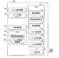
- FIG. 1 is a block diagram showing a schematic configuration of a magnetic data reader as an embodiment of the present invention.
- the magnetic data reader 100 is used for an automatic teller machine (CD), an automatic teller machine (ATM), etc., and magnetic data from a card having a magnetic stripe (hereinafter referred to as magnetic data recorded on the magnetic stripe) Is called “read data”).
- the magnetic data reader 100 includes a card transport mechanism 32, a card position sensor 34, a magnetic reader 36, a memory 38, a CPU 10, and an external interface (IF) unit 40. .
- IF external interface
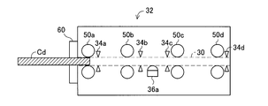
- FIG. 2 is an explanatory view showing a detailed configuration of the card conveyance mechanism, the card position sensor, and the magnetic reading unit shown in FIG.
- the card transfer mechanism 32 includes four pairs of transfer rollers (transfer rollers 50a, 50b, 50c, and 50d) arranged to sandwich the transfer path 30 along the transfer path 30 of the card Cd.
- the transport rollers 50 a, 50 b, 50 c, and 50 d transport the card Cd inserted from the insertion port 60 along the transport path 30.
- Each of the transport rollers 50a, 50b, 50c, 50d is driven by one drive motor (not shown). When the rotational speed of the drive motor changes, the rotational speeds of the transport rollers 50a, 50b, 50c, and 50d change accordingly, and the transport speed of the card Cd changes.
- the card position sensor 34 includes four pairs of sensors (sensors 34 a, 34 b, 34 c, 34 d) arranged so as to sandwich the conveyance path 30 along the conveyance path 30.
- the sensors 34a, 34b, 34c, 34d are arranged in this order along the transport path 30 from the insertion port 60 in a line from the back.
- Each sensor 34a, 34b, 34c, 34d detects the presence or absence of the card Cd and notifies the CPU 10 of it.
- the sensors 34a, 34b, 34c, 34d can be configured by, for example, a light emitting unit (light emitting diode or the like) and a light receiving unit (photo transistor or the like).
- the sensor 34a detects the presence of the card Cd
- the sensor 34b detects the presence of the card Cd
- the card Cd is positioned such that the tip of the magnetic stripe is positioned on the magnetic head 36a described later.
- the sensor 34c detects the presence of the card Cd
- the card Cd is positioned such that the rear end of the magnetic stripe is positioned on the magnetic head 36a described later.
- the sensor 34 d detects the presence of the card Cd, it can be detected that the card Cd has reached the temporary storage section (not shown) at the back of the transport path 30.
- the magnetic reading unit 36 illustrated in FIG. 1 includes the magnetic head 36 a illustrated in FIG. 2.
- the magnetic head 36a is arranged to be in contact with the card Cd transported on the transport path 30, reads the magnetism from the magnetic stripe of the card Cd, and outputs it as magnetic data (voltage value).
- the memory 38 includes a standard information storage unit 38 a and a filter information storage unit 38 b.
- the standard information storage unit 38 a stores in advance information (hereinafter referred to as “standard information”) relating to data recording methods that can be supported by the magnetic data reader 100.
- FIG. 3 is an explanatory view showing the standard information recorded in the standard information storage unit.
- the standard information is configured by a frequency representing data “0” and a frequency representing data “1” set for each of three standards (standard A, standard B, and others).
- Standard A means a standard defined for a predetermined magnetic track (a predetermined magnetic track among a plurality of parallel magnetic tracks included in the magnetic stripe) in a predetermined magnetic recording system by frequency modulation.
- Standard B means a standard defined for another magnetic track different from standard A.
- “Other” means a standard that defines a magnetic recording system different from the standards A and B (for example, a standard that has not been standardized and has been established by the user).
- a predetermined magnetic recording method by frequency modulation for example, a recording method defined by ISO7811-2 is applicable.
- Data is recorded at a predetermined density (the amount of data per unit length) on the magnetic stripes (each magnetic track) of the card Cd.
- Data “0” and data “1” recorded at such data density are output from the magnetic head 36a as signals of predetermined frequencies when they are read when the card Cd is conveyed at a predetermined conveyance speed.
- the frequency of data “0” and the frequency of data “1” are set in advance for each standard (standard A, standard B, etc.).
- the above-mentioned “predetermined transfer speed” is a default transfer speed of the card transfer mechanism 32 (hereinafter referred to as “transfer speed S0”).
- the standard information is set in advance by measuring the frequency of the magnetic data output when the card Cd is transported at the transport speed S0 of the card transport mechanism 32 by an experiment or the like. Specifically, frequencies “fa0” and “fa1” are set to data “0” and “1” of standard A, respectively. Further, frequencies “fb0” and “fb1” are set to data “0” and “1” of standard B, respectively. Further, frequencies “fe0” and “fe0” are set to data “0” and “1” of the other standards, respectively.
- the CPU 10 illustrated in FIG. 1 executes a computer program stored in advance in the memory 38 to perform the conveyance control unit 12, the conveyance speed measurement unit 14, the reading control unit 16, the data conversion unit 18, the filter determination unit 20, and It functions as the filter processing unit 22.
- the transport control unit 12 controls the card transport mechanism 32. Specifically, the transport speed of the card Cd is controlled by controlling the rotation speed of a drive motor (not shown), and the transport direction of the card Cd is controlled by controlling the rotational direction of the drive motor (not shown).
- the transport speed measurement unit 14 measures the speed (transport speed) when the card Cd is transported, based on the position information of the card Cd obtained from the card position sensor 34 (each sensor 34a, 34b, 34c, 34d) .
- the read control unit 16 controls the magnetic reading unit 36 to read the magnetic data recorded on the magnetic stripe by the magnetic head 36 a.
- the data conversion unit 18 converts magnetic data read by the magnetic head 36 a into data of frequency components.
- the filter determination unit 20 determines a filter for removing noise data from the magnetic data.
- the magnetic head 36a outputs, in addition to the recording data read from the magnetic stripe, noise data due to electromagnetic waves emitted from various motors (not shown), coils (not shown) provided near the insertion port 60 for preventing skimming, etc. obtain. Therefore, in the magnetic data reading device 100, such noise data is removed using a filter described later.
- the filter processing unit 22 removes noise data included in the magnetic data using the filter determined by the filter determination unit 20.
- the external IF unit 40 is an interface for connecting to a host device. For example, a computer that controls the overall operation of an automatic teller machine or an automatic teller machine corresponds to the higher-level device.
- the reading accuracy of the magnetic data (recording data) recorded in the magnetic stripe can be improved by executing the magnetic reading process described later.
- the above-mentioned card conveyance mechanism 32 is corresponded to the conveyance part in a claim.
- the transport speed S0 is the reference speed in the claims
- the frequency (fa0 etc.) defined for each standard shown in FIG. 3 is the predetermined first frequency in the claims
- the magnetic reading unit 36 and the reading control unit 16 The reading control unit 16 corresponds to the magnetic reading unit in the claims, and the reading control unit 16 corresponds to the magnetic reading unit and the normality determining unit in the claims.
- FIG. 4 is a flow chart showing the procedure of the magnetic reading process in the first embodiment.
- the read control unit 16 determines the transport direction and speed of the card Cd (step S105).
- the forward direction the direction from the insertion port 60 toward the magnetic head 36a
- the default speed are determined.
- the conveyance control unit 12 controls the drive motor (not shown) to rotate each of the conveyance rollers 50a, 50b, 50c, and 50d so that the conveyance direction and the conveyance speed determined in step S105 can be obtained.
- the transport is started (step S110).
- the reading control unit 16 controls the magnetic reading unit 36 (magnetic head 36a) to read the recording data recorded on the magnetic stripe of the card Cd and stores it in the memory 38. It memorizes (Step S115). At this time, noise data is also read and stored in addition to the recording data. In step S115, the recording data recorded on the plurality of magnetic tracks included in the magnetic stripe are simultaneously read.
- the conveyance control unit 12 controls the drive motor to stop the rotation of the conveyance rollers 50a, 50b, 50c, and 50d, thereby ending the conveyance of the card Cd (Step S120).
- the data conversion unit 18 converts the magnetic data read from the memory 38 into data of frequency components (step S125).
- the filter determination unit 20 determines a filter for removing noise data based on the data of the frequency component obtained in step S125, and the filter processing unit 22 determines noise data from magnetic data read using such a filter. Are removed (step S135).
- the data conversion unit 18 converts (restores) the data of the frequency component after the noise data has been removed in step S135 into magnetic data (voltage value) (step S140). The details of the processing in steps S125 to S140 described above will be described later.
- the read control unit 16 analyzes the magnetic data restored in step S140 and converts it into binary data of “0” and “1” (step S140).
- the read control unit 16 determines whether the magnetic data is normal or not based on the information for determining the normality included in the obtained binary data (step S145).
- the above-mentioned “information for determining normality” is information capable of determining the normality of data before and after conversion between magnetic data and data of frequency components, and, for example, CRC (included in recording data) Data error codes such as cyclic redundancy check (BC) and block check code (BCC) are applicable.
- the read control unit 16 notifies the upper device that the result is normal (step S150), and notifies the upper device in the case of an abnormality that the result is abnormal. (Step S155).
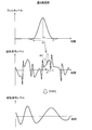
- FIG. 5 is an explanatory view schematically showing processing from step S125 to step S135 shown in FIG.
- the top row in FIG. 5 shows the magnetic data obtained in step S115.
- the horizontal axis represents time (time)
- the vertical axis represents the magnetic signal level (voltage).
- the horizontal axis represents frequency
- the vertical axis represents frequency (amplitude).
- the magnetic data shown in the top row of FIG. 5 is converted into data of frequency components shown in the second row.
- transformation for example, Fourier transformation or wavelet transformation can be adopted.
- the filter F is a frequency filter determined as a frequency range in which recording data exists. Therefore, magnetic data that appears as a frequency not included in the filter F is removed as noise data. Therefore, as shown at the bottom of FIG. 5, the magnetic data (recording data) is extracted (reconstructed) as a composite wave of waves of two frequencies representing “0” and “1”.
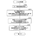
- FIG. 6 is a flowchart showing a detailed procedure of step S130 (filter processing) shown in FIG.
- FIG. 7 is an explanatory view schematically showing processing contents of step S130 (filter processing) shown in FIG.
- the filter determination unit 20 controls the transport speed measurement unit 14 to transport the card Cd (hereinafter, “transport speed Sc”). Is identified (step S205).
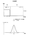
- the filter determination unit 20 determines the median value M of the filter for each of the data “0” and “1” based on the transport speed Sc identified in step S205, the default transport speed S0, and the standard information. (Step S210). For example, as shown in FIG. 7, when the standard corresponding to the magnetic track to be filtered is standard B, a filter for data “0” (a filter for defining a frequency range representing data “0”) Median value M (median value Mb0) is determined as a value obtained by multiplying frequency “fb0” by transport speed Sc and dividing by the transport speed S0.
- the median value Mb0 is determined by multiplying the frequency “fb0” previously set in the standard B by the ratio (ratio) of the transport speed Sc to the transport speed S0.
- median value M (median value Mb1) of a filter for data “1” is a frequency “fb1” preset in standard B. It is determined by multiplying the ratio (ratio) of the transport speed Sc to the transport speed S0.
- the ratio of the transport speed when actually transporting the card Cd to the default transport speed is multiplied for the following reason.
- the frequency of the magnetic data (recording data) indicating data “0” and “1” is set to the frequency assumed based on the standard (standard information) (The frequency of For example, when the actual transport speed Sc is higher (faster) than the default transport speed S0, the frequency of the magnetic data indicating data “0” and “1” is higher than the frequency assumed based on the standard.
- the frequency of the magnetic data indicating data “0” and “1” is lower. Therefore, in the magnetic data reading apparatus 100, recording data (data (data) when conveyed at the conveyance speed Sc by multiplying the ratio of the actual conveyance speed Sc to the conveyance speed S0 which is the conveyance speed at the time of determining the standard information. By obtaining the frequency of “0”, “1”), even when the transport speed changes, the recording data is read accurately.
- the filter determination unit 20 determines filters (frequency ranges) for each of the data "0" and "1” from the median M determined in step S210 and a predetermined tolerance, and combines these filters.
- the frequency range is determined as a filter (filter F shown in FIG. 5) used in noise data removal (step S215).
- the tolerance is set in advance, and the tolerance is applied (added or added) to the median M (for example, medians Mb0 and Mb1 in FIG. 7) determined in step S210. Deducted).
- the filter processing unit 22 removes the noise data by applying the filter determined in step S215 to the data of the frequency component obtained in step S125 and deleting the magnetic data corresponding to the frequency deviated from the filter. (Step S220).
- the frequency set in advance for the recording data (data “0”, “1”) is taken.
- the frequency obtained by multiplying the ratio of the actual card transfer speed Sc to the card transfer speed S0 at the time of determining the frequency is set as the median value M of the frequency of the recording data in the read magnetic data . Therefore, the transport speed Sc is different from the transport speed S0 due to the aged deterioration or replacement of the card transport mechanism 32, and the recorded data can be read accurately even when the frequency of the magnetic data representing the recorded data changes. Therefore, the reading accuracy of the recording data can be improved.
- FIG. 8 is a flowchart showing the procedure of the magnetic reading process in the second embodiment.
- the magnetic data reading device of the second embodiment differs from the magnetic data reading device 100 of the first embodiment in that steps S152, S170, and S175 are additionally executed in the magnetic reading process.
- the procedure and apparatus configuration are the same as the magnetic data reader 100 of the first embodiment.
- reading of the magnetic data is retried until the predetermined number of times is reached, and the transport speed is changed every retry.
- step S145 when it is determined in step S145 that the magnetic data is not normal (step S145: NO), the reading control unit 16 reads the magnetism (steps S105 to S145) as the upper limit number of retries (for example, It is determined whether or not it has been executed until three times (step S152). If it is determined that the process has been executed until the retry upper limit number is reached (step S152: YES), the above-described step S155 is performed, and the host apparatus is notified that it is abnormal.
- step S152 the reading control unit 16 compares the setting value of the transport speed of the card Cd with the previous transport speed.
- the transport speed is changed to a different transport speed (step S170).
- step S170 the transport speed is changed to a lower (slower) transport speed than the previous transport speed.
- a plurality of transport speeds are set in advance, and it is possible to select and set a speed lower than the previous one among these speeds. Further, the amount of deceleration is set in advance, and a new conveyance speed can be set by subtracting the amount of deceleration from the previous conveyance speed.
- the conveyance control unit 12 controls the drive motor (not shown) to reversely rotate the conveyance rollers 50a, 50b, 50c and 50d, and returns the card Cd from the temporary storage part of the card (not shown) to the insertion port 60 (step S175). . Thereafter, the process returns to step S105, and the processes of steps S105 to S155 are performed again.
- FIG. 9 is an explanatory view showing an example of data of frequency components before and after the change of the card transport speed in the second embodiment.
- the upper part shows data of frequency components before the card transport speed change
- the lower part shows data of frequency components after the card transport speed change.
- the horizontal axis and the vertical axis are the same as the second and third stages in FIG.
- the frequency domain Dr1 mainly containing the recording data and the frequency domain Nr1 mainly containing the noise data have an overlapping area Wr1.
- the frequency of the recording data and the frequency of the noise data are close to or equal to each other, and when filtering is performed using the filter F, the recording data is regarded as noise data and removed. I will.
- the frequency of the recording data becomes lower. Therefore, the frequency domain Dr2 mainly including the recording data is in the lower frequency range (the upper limit frequency is lowered).
- the frequency region Nr1 mainly including noise data is not changed. This is because the frequency of the noise data does not change because the frequency of the electromagnetic wave generated from the various motors and coils for preventing skimming does not change even if the transport speed of the card changes. Therefore, as shown in the lower part of FIG. 9, since there is no overlap between the frequency domain Dr2 and the frequency domain Nr1, almost all noise data is removed when the filter processing is performed using the filter F. Deletion of the recorded data is suppressed.
- the magnetic data reader of the second embodiment described above has the same effect as the magnetic data reader 100 of the first embodiment.
- the transport speed of the card Cd is changed low, so that the frequency of the recording data can be changed low to be further away from the frequency range of the noise data. Therefore, a large amount of noise data can be deleted in the filtering process, and deletion of the recording data can be suppressed.
- FIG. 10 is a flowchart showing the procedure of the magnetic reading process in the third embodiment.
- the magnetic data reading apparatus of the third embodiment is the magnetic reading system of the first embodiment in that steps S121, S122, and S123 are additionally executed in the magnetic reading process, and that step S130a is executed instead of step S130.
- steps S121, S122, and S123 are additionally executed in the magnetic reading process, and that step S130a is executed instead of step S130.
- other procedures and apparatus configuration in the magnetic reading process are the same as the magnetic data reader 100 of the first embodiment.
- the recording data (data "0", "1") is out of specification by correcting (adjusting) the upper limit value in the frequency range of the filter based on the read magnetic data. Even in the case where the recording is performed so as to have the frequency of 1, the recording data can be read normally.
- the recording of data “0” and “1” that results in non-standard frequencies is, for example, when magnetic data is recorded on a magnetic stripe, when recording is performed based on an unstandardized proprietary standard, This may occur when the data density at the time of data writing deviates from the standard for some reason (for example, a defect of the magnetic recording apparatus).
- a card on which data “0” and “1” are recorded so as to have an out-of-standard frequency will be referred to as an “out-of-standard card” for the convenience of description.
- the data conversion unit 18 reads the magnetic data from the memory 38, and the signal level (voltage) of the magnetic data is equal to or higher than a predetermined value. Certain magnetic data is extracted (step S121), and the extracted magnetic data is converted into data of frequency components (step S122). The filter determination unit 20 determines the filter limit value based on the data of the frequency component obtained in step S122 (step S123).
- FIG. 11 is an explanatory view schematically showing the process of steps S121 to S123 shown in FIG.
- the upper part in FIG. 11 shows data of frequency components obtained when step S125 is performed without performing steps S121 to S123.
- filtering is performed using a filter F set based on a predetermined standard (standard A, standard B, etc.) and transport speed. Since the frequency domain Dr3 in which the recording data is mainly included is wider than the frequency range of the filter F, the frequency domain Wr2 in which the recording data is removed is relatively wide.
- the middle row in FIG. 11 is an explanatory view schematically showing the process of step S121.
- step S121 for example, magnetic data having a magnetic signal level (voltage) of + Vth or more and ⁇ Vth or less is extracted.
- the lower part in FIG. 11 is an explanatory view schematically showing processing of steps S122 and S123.
- the frequency of noise present in the high frequency range is smaller than that in the upper part of FIG. This is because data with high magnetic signal levels is relatively insusceptible to noise compared to low data, so when such data is converted to data of frequency components, the frequency of noise frequency is relatively small. It is because The reason why the level of the magnetic signal is low is, for example, that the card Cd (magnetic stripe) is demagnetized in a part of the magnetic stripe, etc., because it approaches a magnetic material or the like having strong magnetism. .
- a threshold is provided in advance for the frequency (amplitude), and in step S123, the frequency at the intersection XP of the data of the frequency component and the threshold is determined as the upper limit of the filter. Be done. Although there are two intersections of the data of the frequency component and the threshold value, among these two intersections, the frequency at the intersection with higher frequency is determined as the upper limit value of the filter.
- step S123 After step S123 is performed, step S125 described above is performed, and then step S130a is performed.
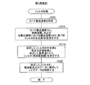
- FIG. 12 is a flowchart showing a detailed procedure of the filter process (step S130a) in the third embodiment.
- the filtering process of the third embodiment is different from the filtering process (step S130) of the first embodiment shown in FIG. 6 in that step S215a is executed instead of step S215, and other procedures are the same as those of the first embodiment. It is.
- the filter determination unit 20 performs the filter (frequency for each of the data "0" and "1" from the median M determined in step S210 and the predetermined tolerance. A range is determined, and a filter is determined on the basis of the frequency domain obtained by combining these filters and the upper limit value determined in the above-mentioned step S123 (step S215a). When the filter is determined, the above-described step S220 is performed to complete the filtering process.
- FIG. 13 is an explanatory view showing a filter determined in the third embodiment.
- the lower part shows the filter F1 determined in step S215a.
- the upper part is the same as the upper part of FIG. 11, and the middle part is the same as the lower part of FIG.
- the upper limit value of the filter (frequency of the intersection point XP) determined in the lower part of FIG. 11 is higher than the upper limit value of the assumed filter F (in other words, the filter F set in the first embodiment) shown in the upper part of FIG. Therefore, as shown in the lower part of FIG. 11, the upper limit value of the filter determined in step S215a of the third embodiment is higher than that of the filter F, and the filter range is wide. Therefore, in the lower part of FIG. 11, the area Wr3 from which the recording data is removed is relatively narrow.
- the magnetic data reader of the third embodiment described above has the same effect as the magnetic data reader 100 of the first embodiment.
- the intersection of the data of the frequency component and the threshold is determined, and the frequency of the intersection (the higher frequency of the frequencies of the two intersections) is determined as the upper limit value of the filter. Even when 1 ′ ′) is recorded so as to have a frequency outside the expected standard, it is possible to remove much noise and to suppress deletion of the recording data in the filtering process.
- data of high magnetic signal level is extracted before the intersection of data of frequency component and threshold value, and such data is converted to obtain data of frequency component, so that the magnetic signal level is low. Data susceptible to noise (that is, there are a lot of noise when converted to data of frequency components in step S122) can be excluded.
- FIG. 14 is a flowchart showing the procedure of the magnetic reading process in the fourth embodiment.
- FIG. 15 is a flowchart showing the detailed procedure of the filtering process in the fourth embodiment.
- the magnetic data reading apparatus according to the fourth embodiment additionally executes steps S180, S185, and S190 in the magnetic reading process, executes step S130b instead of step S130, and omits step S135.
- other procedures and apparatus configurations in the magnetic reading process are the same as the magnetic data reader 100 of the first embodiment.
- the filtering process is realized by deleting the magnetic data corresponding to the frequency deviated from the determined filter (frequency range).
- the determined filter (frequency range) is converted into time axis data, and the converted time axis data is applied to the magnetic data obtained in step S115. .
- the filter determination unit 20 determines a filter (step S180).
- the detailed procedure of this filter determination is the same as steps S205 to S215 of the first embodiment shown in FIG.
- the data conversion unit 18 sets the characteristics of the frequency components of the filter based on the filter (frequency range) obtained in step S180 (step S185).
- the data conversion unit 18 converts the characteristic of the frequency component of the filter set in step S185 into data of a time component (step S190).
- FIG. 16 is an explanatory view schematically showing the process of steps S185 and S190 in the fourth embodiment.
- the upper part shows the characteristic of the frequency component of the filter F obtained in step S185
- the lower part shows data of the time component of the filter F obtained in step S190.
- the frequency domain of filter F (that is, frequency domain Dr4 mainly including recording data) has a predetermined frequency larger than 0, and other frequency domains (that is, noise data is The characteristic of the frequency component in which the frequency is 0 is set in the mainly included frequency domain Nr2).
- step S190 the characteristics of the frequency components shown in the upper part of FIG. 16 are converted into data of time components shown in the lower part of FIG. As shown in the lower part of FIG. 16, the data of the time component obtained in step S190 is obtained as a mountain-shaped waveform with a time width ⁇ t centered on time t1.
- step S130 b filter processing is performed (step S130 b).
- the filtering process of the fourth embodiment is executed by applying the data of the time component obtained in step S190 to each magnetic data obtained in step S115, as shown in FIG. 15 (step S305). ).
- FIG. 17 is an explanatory view schematically showing the contents of step S130 b (filter processing) in the fourth embodiment.
- the upper part of FIG. 17 is the same as the lower part of FIG.
- the middle row shows the magnetic data obtained in step S115
- the lower row shows the magnetic data obtained in step S305.
- step S305 as shown in the middle of FIG. 17, for example, when data of the time component in the upper stage of FIG. 17 is applied to the magnetic data da1 at time ta, each existing in the range of time width ⁇ t centered on time ta
- the magnetic data (magnetic signal level) is multiplied by the filter level at the corresponding time in the data of the time component, and the obtained values are added to obtain magnetic data at time ta.
- the time component data shown in the upper part of FIG. 17 is weighted and added to obtain magnetic data of the time ta.
- noise is removed from the magnetic data shown in the middle part of FIG. 17, and the magnetic data is a composite wave of waves of two frequencies representing “0” and “1”. It is extracted.
- the magnetic data reader of the fourth embodiment described above has the same effect as the magnetic data reader 100 of the first embodiment.
- step S170 of the magnetic reading process in the second embodiment the card transport speed is changed to a lower (slow) speed, but may be changed to a higher (fast) speed instead of the lower speed.
- the frequency of the noise data is lower than the frequency of the recording data
- the noise data and the recording data can be easily separated by increasing the frequency of the recording data by increasing the transport speed.
- step S121 extraction of magnetic data whose magnetic signal level is equal to or more than a predetermined value
- step S123 determination of the filter limit value
- the present invention is not limited to this.
- step S145: NO when it is determined that the magnetic data is not normal (step S145: NO), it is determined whether the upper limit number of retries has been reached (step If not reached, the above-mentioned steps S121 to S123 may be executed to return to step S105. With such a configuration, it is not necessary to execute steps S121 to S123 when a card within a standard assumed in advance is inserted, so that the magnetic data reading process can be completed in a short period of time.
- data to be processed when obtaining an intersection with a threshold is data obtained by converting magnetic data having a signal level (voltage) of a predetermined value or more into data of a frequency component.
- step S121 may be omitted, all magnetic data (entire read data) may be converted into data of frequency components, and the obtained data may be used as a target when obtaining an intersection with a threshold.
- the upper limit of the filter can be determined with high accuracy.
- the lower limit of the filter may be determined in addition to or in place of the upper limit of the filter.
- the frequency of the intersection point of lower frequency is set as the lower limit of the filter. You can also.
- the filter is determined as the frequency range in which the recording data exists, but the present invention is not limited to this.
- the frequency range in which the noise data is present may be determined as a filter.
- magnetic data appearing as a frequency included in the filter can be removed as noise data, and magnetic data appearing as a frequency not included in the filter can be treated as recording data.
- the standards recorded in the standard information are three types (standard A, standard B, and others), but any standard can be recorded in the standard information.
- the medium having the magnetic stripe is a card, but not limited to a card, any medium such as a passbook or a book can be adopted.
- the magnetic data reading apparatus of each embodiment performs the reading process of the magnetic data, but in addition to the reading of the magnetic data, the writing of the magnetic data can also be performed.
Landscapes
- Engineering & Computer Science (AREA)
- Signal Processing (AREA)
- Artificial Intelligence (AREA)
- Computer Vision & Pattern Recognition (AREA)
- Physics & Mathematics (AREA)
- General Physics & Mathematics (AREA)
- Theoretical Computer Science (AREA)
- Signal Processing For Digital Recording And Reproducing (AREA)
Abstract
磁気データ読取装置は、媒体を搬送する搬送部と、搬送されている媒体の搬送速度を測定する搬送速度測定部と、搬送されている媒体の磁気ストライプから記録データを読み取る磁気読取部と、磁気読取部による読み取りにより得られた磁気データからノイズデータを除去する際に用いられる周波数フィルタを、測定された搬送速度に基づき決定するフィルタ決定部と、決定された周波数フィルタを用いて、読取データからノイズデータを除去するフィルタ処理部と、を備える。
Description
本発明は、カード等の媒体が有する磁気ストライプに記録されている磁気データの読み取りに関する。
従来から、現金自動支払い機(CD : Cash Dispenser)や、現金自動預け払い機(ATM : Automatic Teller Machine)等の現金取引処理装置において、キャッシュカードやクレジットカード等の磁気ストライプを有するカードが用いられている。これらの装置では、カードが搬送される際に、磁気ヘッドによって磁気ストライプに記録されている磁気データ(以下、「記録データ」と呼ぶ)が読み取られる。磁気ヘッドによって読み取られた磁気データには、各種ノイズが混入し得る。例えば、現金取引処理装置が有する各種モータやスキミング防止用のコイルから発生される電磁波に起因するノイズが混入し得る。
そこで、読み取られた磁気データからノイズを取り除くために、ローパスフィルタを用いて磁気データ(信号)の高周波成分を削除する方法が提案されている。
上述したローパスフィルタを用いてノイズを除去する技術では、読み取られた磁気データが周波数成分のデータに変換され、周波数フィルタを用いて比較的高い周波数のノイズデータが取り除かれる。ここで、周波数フィルタの周波数範囲は固定されているため、カードの搬送速度が変化して記録データの周波数が変化した場合に、記録データの一部がノイズとみなされて除去されてしまい、記録データの読み取り精度が低下するという問題があった。なお、カード搬送速度の変化は、例えば、カード搬送機構の劣化やカード搬送機構の交換などにより生じ得る。
また、上述したローパスフィルタを用いてノイズを除去する技術では、ノイズが低周波である場合や、記録データと同程度の周波数である場合には、ノイズを取り除くことができず、記録データの読み取り精度が低下するという問題があった。
なお、これらの問題は、カードに限らず、通帳などの磁気ストライプを有する任意の媒体について起こり得る。
本発明は、上述した問題の少なくとも一部を解決するためになされたものであり、磁気ストライプに記録されている磁気データの読み取り精度を向上させることを目的とする。
本発明は、上述の課題の少なくとも一部を解決するためになされたものであり、以下の形態又は適用例として実現することが可能である。
[適用例1]磁気ストライプを有する媒体から前記磁気ストライプに記録されている磁気データを読み取る磁気データ読取装置であって、前記媒体を搬送する搬送部と、前記搬送される媒体の搬送速度を測定する搬送速度測定部と、前記搬送される媒体の前記磁気ストライプから前記磁気データを読み取る磁気読取部と、前記読み取られた磁気データを周波数成分のデータに変換するデータ変換部と、前記磁気データに含まれる記録データとノイズデータとのうち、前記ノイズデータを除去する際に用いられる周波数範囲で規定されるフィルタを、前記測定された搬送速度に基づき決定するフィルタ決定部と、前記決定されたフィルタを前記周波数成分のデータに適用することにより、前記磁気データから前記ノイズデータを除去するフィルタ処理部と、を備える、磁気データ読取装置。
適用例1の磁気データ読取装置によると、媒体を搬送した際に測定された搬送速度に基づきフィルタ(周波数範囲)が決定されるので、搬送速度が変化してフィルタされるべき周波数範囲が変化した場合であっても、適切な周波数範囲をフィルタとして決定することが可能となる。したがって、ノイズを除去しつつ有効なデータが除去されることを抑制でき、磁気ストライプに記録されている磁気データの読み取り精度を向上させることができる。
[適用例2]適用例1に記載の磁気データ読取装置において、前記磁気ストライプには、前記記録データが、前記媒体が前記搬送部により所定の基準速度で搬送されて前記磁気読取部により前記磁気データが読み取られ、かつ、前記周波数成分のデータに変換された場合に、所定の第1の周波数のデータとなるような密度で記録されており、前記フィルタ決定部は、前記所定の基準速度に対する前記測定された搬送速度の割合を前記所定の第1の周波数に乗じて得られた周波数に基づき、前記周波数範囲を決定する、磁気データ読取装置。
このような構成により、搬送速度が基準速度よりも高く(速く)変化して、記録データを周波数成分のデータに変換した場合に所定の第1の周波数よりも高くなった場合や、搬送速度が基準速度よりも低く(遅く)変化して、記録データを周波数成分のデータに変換した場合に所定の第1の周波数よりも低くなった場合などにおいても、適切にノイズデータを除去すると共に、記録データを除去することを抑制できる。
[適用例3]適用例1または適用例2に記載の磁気データ読取装置において、さらに、前記ノイズデータが除去された前記磁気データの示す情報に基づき、前記ノイズデータが除去された前記磁気データの正常性を判定する正常性判定部と、前記搬送部による前記媒体の搬送速度を調整する搬送制御部と、を備え、前記搬送制御部は、前記正常性判定部により正常でないと判定された場合に、前記搬送速度を変更し、前記搬送部は、前記変更後の搬送速度で前記媒体を再搬送し、前記磁気読取部は、前記媒体の再搬送の際に、前記磁気データを再読み取りし、前記搬送速度測定部は、前記媒体の再搬送の際に前記媒体の搬送速度を再測定し、前記フィルタ決定部は、前記媒体の再搬送の際に測定された前記搬送速度に基づき、前記周波数範囲を再決定し、前記フィルタ処理部は、前記再決定された周波数範囲のフィルタを用いて、前記ノイズデータを除去する、磁気データ読取装置。
このような構成により、搬送速度を変更することにより、記録データの周波数(記録データを周波数のデータに変更した場合に得られる周波数)を積極的に変化させることができる。一方、ノイズデータの周波数(記録データを周波数のデータに変更した場合に得られる周波数)は、媒体の搬送速度を変更しても変更しない。したがって、搬送速度を変更することにより、周波数成分のデータにおける記録データの周波数とノイズデータの周波数を異ならせることができるので、記録データとノイズデータとを容易に分離させることができる。また、媒体を再搬送した際の搬送速度に基づきフィルタが決定されるので、搬送速度の変化に起因して記録データの周波数が変化した場合であっても、ノイズデータを除去しつつ記録データを削除することを抑制できる。
[適用例4]適用例3に記載の磁気データ読取装置において、前記搬送制御部は、前記正常性判定部により正常でないと判定された場合に、前記媒体の再搬送の際の搬送速度を、より低く変更する、磁気データ読取装置。
このような構成により、記録データの周波数を前回搬送時に比べてより低くすることができる。したがって、ノイズデータの周波数が記録データの周波数よりも高い場合や、同程度の場合において、記録データの周波数とノイズデータの周波数をより大きく異ならせる(大きく離す)ことができ、記録データとノイズデータとを容易に分離させることができる。
[適用例5]適用例1ないし適用例4のいずれかに記載の磁気データ読取装置において、記フィルタ決定部は、前記読み取られた磁気データのうち、磁気信号の強度が所定の強度以上である磁気データを抽出し、前記データ変換部は、前記抽出された磁気データを周波数成分のデータに変換し、前記フィルタ決定部は、前記抽出された磁気データを変換して得られた周波数成分のデータに基づき、前記周波数範囲の限界値を決定すると共に、前記測定された搬送速度に基づき決定した前記周波数範囲を、前記決定された限界値を用いて修正する、磁気データ読取装置。
このような構成により、周波数成分のデータに基づきフィルタ(周波数範囲)の限界値を決定するので、磁気ストライプに記録されている記録データが、周波数成分のデータに変換した場合に予定していない周波数となる場合であっても、ノイズデータと記録データとを適切に分離し得るフィルタを決定することができる。加えて、周波数成分のデータに変換する際の対象となる磁気データは、磁気強度が所定の強度以上であり、ノイズの影響を比較的受け難いデータである。したがって、周波数成分のデータにおいて、ノイズの周波数の影響を低く抑えて記録データの周波数範囲を明確にすることができる。それゆえ、フィルタの限界値を高い精度で決定することができる。
[適用例6]適用例1ないし適用例5のいずれかに記載の磁気データ読取装置において、前記データ変換部は、前記読み取られた磁気データを、フーリエ変換又はウェーブレット変換により、前記周波数成分のデータに変換する、磁気データ読取装置。
このような構成により、磁気データを周波数成分のデータに変換することができる。
[適用例7]磁気ストライプを有する媒体から前記磁気ストライプに記録されている磁気データを読み取る方法であって、(a)前記媒体を搬送する工程と、(b)前記搬送される媒体の搬送速度を測定する工程と、(c)前記搬送される媒体の前記磁気ストライプから前記磁気データを読み取る工程と、(d)前記読み取られた磁気データを周波数成分のデータに変換する工程と、(e)前記磁気データに含まれる記録データとノイズデータとのうち、前記ノイズデータを除去する際に用いられる周波数範囲で規定されるフィルタを、前記測定された搬送速度に基づき決定する工程と、(f)前記決定されたフィルタを前記周波数成分のデータに適用することにより、前記磁気データから前記ノイズデータを除去する工程と、を備える、方法。
適用例1の方法によると、媒体を搬送した際に測定された搬送速度に基づきフィルタ(周波数範囲)が決定されるので、搬送速度が変化してフィルタされるべき周波数範囲が変化した場合であっても、適切な周波数範囲をフィルタとして決定することが可能となる。したがって、ノイズを除去しつつ有効なデータが除去されることを抑制でき、磁気ストライプに記録されている磁気データの読み取り精度を向上させることができる。
[適用例8]磁気データ読取装置を用いて磁気ストライプを有する媒体から前記磁気ストライプに記録されている磁気データを読み取るためのコンピュータプログラムであって、前記媒体を搬送する機能と、前記搬送される媒体の搬送速度を測定する機能と、前記搬送される媒体の前記磁気ストライプから前記磁気データを読み取る機能と、前記読み取られた磁気データを周波数成分のデータに変換する機能と、前記磁気データに含まれる記録データとノイズデータとのうち、前記ノイズデータを除去する際に用いられる周波数範囲で規定されるフィルタを、前記測定された搬送速度に基づき決定する機能と、前記決定されたフィルタを前記周波数成分のデータに適用することにより、前記磁気データから前記ノイズデータを除去する機能と、を前記磁気データ読取装置が有するコンピュータに実現させるためのプログラム。
適用例8のプログラムによると、媒体を搬送した際に測定された搬送速度に基づきフィルタ(周波数範囲)が決定されるので、搬送速度が変化してフィルタされるべき周波数範囲が変化した場合であっても、適切な周波数範囲をフィルタとして決定することが可能となる。したがって、ノイズを除去しつつ有効なデータが除去されることを抑制でき、磁気ストライプに記録されている磁気データの読み取り精度を向上させることができる。
[適用例9]適用例8に記載のプログラムを記録したコンピュータ読み取り可能な記録媒体。
このような構成により、かかる記録媒体を用いてコンピュータにプログラムを読み取らせ、各機能を実現させることができる。
A.第1実施例:
A1.装置構成:
図1は、本発明の一実施例としての磁気データ読取装置の概略構成を示すブロック図である。磁気データ読取装置100は、現金自動預け払い機(CD)や、現金自動預け払い機(ATM)等に用いられ、磁気ストライプを有するカードから磁気データ(以下、磁気ストライプに記録されている磁気データを「読取データ」と呼ぶ)を読み取る。図1に示すように、磁気データ読取装置100は、カード搬送機構32と、カード位置センサ34と、磁気読取部36と、メモリ38と、CPU10と、外部インターフェイス(IF)部40を備えている。
A1.装置構成:
図1は、本発明の一実施例としての磁気データ読取装置の概略構成を示すブロック図である。磁気データ読取装置100は、現金自動預け払い機(CD)や、現金自動預け払い機(ATM)等に用いられ、磁気ストライプを有するカードから磁気データ(以下、磁気ストライプに記録されている磁気データを「読取データ」と呼ぶ)を読み取る。図1に示すように、磁気データ読取装置100は、カード搬送機構32と、カード位置センサ34と、磁気読取部36と、メモリ38と、CPU10と、外部インターフェイス(IF)部40を備えている。
図2は、図1に示すカード搬送機構、カード位置センサ、および磁気読取部の詳細構成を示す説明図である。カード搬送機構32は、カードCdの搬送路30に沿って搬送路30を挟むように配置された一対の搬送ローラを4組(搬送ローラ50a,50b,50c,50d)備えている。各搬送ローラ50a,50b,50c,50dは、挿入口60から挿入されたカードCdを、搬送路30に沿って搬送する。各搬送ローラ50a,50b,50c,50dは、いずれも図示しない1つの駆動モータにより駆動される。かかる駆動モータの回転速度が変化すると、それに従って各搬送ローラ50a,50b,50c,50dの回転速度が変化してカードCdの搬送速度が変化する。
カード位置センサ34は、搬送路30に沿って搬送路30を挟むように配置された一対のセンサを4組(センサ34a,34b,34c,34d)備えている。センサ34a,34b,34c,34dは、この順序で、搬送路30に沿って挿入口60から奥に向かって並んで配置されている。各センサ34a,34b,34c,34dは、カードCdの有無を検出し、CPU10に通知する。センサ34a,34b,34c,34dは、例えば、発光部(発光ダイオード等)と受光部(フォトトランジスタ等)とにより構成することができる。センサ34aがカードCd有りを検出することにより、挿入口60から挿入されたカードCdが、搬送ローラ50aにより挟持されたことを検出できる。センサ34bがカードCd有りを検出することにより、磁気ストライプの先端が後述の磁気ヘッド36a上に位置するように、カードCdが位置したことを検出できる。センサ34cがカードCd有りを検出することにより、磁気ストライプの後端が後述の磁気ヘッド36a上に位置するように、カードCdが位置したことを検出できる。センサ34dがカードCd有りを検出することにより、搬送路30の奥にある図示しない一時貯留部に、カードCdが達したことを検出できる。
図1に示す磁気読取部36は、図2に示す磁気ヘッド36aを備えている。磁気ヘッド36aは、搬送路30を搬送されるカードCdと接触するように配置され、カードCdが有する磁気ストライプから磁気を読み取り、磁気データ(電圧値)として出力する。
図1に示すように、メモリ38は、規格情報格納部38a及びフィルタ情報格納部38bを備えている。規格情報格納部38aは、磁気データ読取装置100において対応可能なデータ記録方式に関する情報(以下、「規格情報」と呼ぶ)を予め格納している。
図3は、規格情報格納部に記録されている規格情報を示す説明図である。図3に示すように、規格情報は、3つの規格(規格A,規格B,その他)のそれぞれについて設定された、データ「0」を表す周波数及びデータ「1」を表す周波数により構成されている。「規格A」は、周波数変調による所定の磁気記録方式における所定の磁気トラック(磁気ストライプが有する並列する複数の磁気トラックのうちの所定の磁気トラック)について定められた規格を意味する。「規格B」は、規格Aとは異なる他の磁気トラックについて定められた規格を意味する。「その他」は、規格A,Bとは異なる磁気記録方式を定めた規格(例えば、標準化されておらずユーザが独自に定めた規格)を意味する。なお、周波数変調による所定の磁気記録方式としては、例えば、ISO7811-2で規定された記録方式が該当する。
カードCdが有する磁気ストライプ(各磁気トラック)には、所定の密度(単位長さ当たりのデータ量)でデータが記録されている。かかるデータ密度で記録されているデータ「0」及びデータ「1」は、所定の搬送速度でカードCdが搬送される際に読み取られると、それぞれ所定の周波数の信号として磁気ヘッド36aから出力される。規格情報では、各規格(規格A,規格B,その他)について、データ「0」の周波数及びデータ「1」の周波数が予め設定されている。なお、上述の「所定の搬送速度」とは、カード搬送機構32におけるデフォルトの搬送速度(以下「搬送速度S0」と呼ぶ)である。規格情報は、予め実験等により、カード搬送機構32の搬送速度S0でカードCdを搬送した際に出力される磁気データの周波数を測定して設定されている。具体的には、規格Aのデータ「0」,「1」に、それぞれ周波数「fa0」,「fa1」が設定されている。また、規格Bのデータ「0」,「1」に、それぞれ周波数「fb0」,「fb1」が設定されている。また、その他の規格のデータ「0」,「1」に、それぞれ周波数「fe0」,「fe0」が設定されている。
図1に示すCPU10は、メモリ38に予め格納されているコンピュータプログラムを実行することにより、搬送制御部12、搬送速度測定部14、読取制御部16、データ変換部18、フィルタ決定部20、及びフィルタ処理部22として機能する。
搬送制御部12は、カード搬送機構32を制御する。具体的には、図示しない駆動モータの回転数を制御することによりカードCdの搬送速度を制御し、また、図示しない駆動モータの回転方向を制御することによりカードCdの搬送方向を制御する。搬送速度測定部14は、カード位置センサ34(各センサ34a,34b,34c,34d)から得られるカードCdの位置情報に基づき、カードCdが搬送されている際の速度(搬送速度)を測定する。読取制御部16は、磁気読取部36を制御して、磁気ヘッド36aにより磁気ストライプに記録されている磁気データを読み取らせる。データ変換部18は、磁気ヘッド36aにより読み取られた磁気データを周波数成分のデータに変換する。フィルタ決定部20は、磁気データからノイズデータを取り除くためのフィルタを決定する。磁気ヘッド36aは、磁気ストライプから読み取った記録データに加えて、図示しない各種モータや、スキミング防止用に挿入口60付近に設けられた図示しないコイル等から発せられる電磁波に起因するノイズデータを出力し得る。そこで、磁気データ読取装置100では、後述のフィルタを用いてかかるノイズデータを取り除く。フィルタ処理部22は、フィルタ決定部20により決定されたフィルタを用いて磁気データに含まれるノイズデータを取り除く。外部IF部40は、上位装置と接続するためのインターフェイスである。上位装置としては、例えば、現金自動預け払い機や現金自動預け払い機の全体動作を制御するコンピュータが該当する。
以上の構成を有する磁気データ読取装置100では、後述する磁気読み取り処理を実行することにより、磁気ストライプに記録されている磁気データ(記録データ)の読み取り精度を向上させることができる。
なお、前述のカード搬送機構32は、請求項における搬送部に相当する。また、搬送速度S0は請求項における基準速度に、図3に示す各規格について定められた周波数(fa0等)は請求項における所定の第1の周波数に、磁気読取部36及び読取制御部16は請求項における磁気読取部に、読取制御部16は請求項における磁気読取部及び正常性判定部に、それぞれ相当する。
A2.磁気読み取り処理:
図4は、第1実施例における磁気読み取り処理の手順を示すフローチャートである。磁気データ読取装置100では、カードCdが挿入されると、磁気読み取り処理が実行される。読取制御部16は、カードCdの搬送方向および速度を決定する(ステップS105)。ここでは、正方向(挿入口60から磁気ヘッド36aに向かう方向)及びデフォルトの速度が決定される。
図4は、第1実施例における磁気読み取り処理の手順を示すフローチャートである。磁気データ読取装置100では、カードCdが挿入されると、磁気読み取り処理が実行される。読取制御部16は、カードCdの搬送方向および速度を決定する(ステップS105)。ここでは、正方向(挿入口60から磁気ヘッド36aに向かう方向)及びデフォルトの速度が決定される。
搬送制御部12は、図示しない駆動モータを制御して、各搬送ローラ50a,50b,50c,50dを回転させることにより、ステップS105で決定された搬送方向及び搬送速度となるように、カードCdの搬送を開始する(ステップS110)。
読取制御部16は、カードCdの先端が磁気ヘッド36aに達すると、磁気読取部36(磁気ヘッド36a)を制御して、カードCdの磁気ストライプに記録されている記録データを読み取ってメモリ38に記憶させる(ステップS115)。このとき、記録データ記録データに加えてノイズデータも読み取られて記憶される。なお、ステップS115では、磁気ストライプに含まれる複数の磁気トラックに記録されている記録データが同時に読み取られる。
搬送制御部12は、センサ34dがカードCdの先端を検出すると、駆動モータを制御して各搬送ローラ50a,50b,50c,50dの回転を停止させることにより、カードCdの搬送を終了させる(ステップS120)。
データ変換部18は、メモリ38から読み出した磁気データを周波数成分のデータに変換する(ステップS125)。フィルタ決定部20は、ステップS125により得られた周波数成分のデータに基づき、ノイズデータを除去するためのフィルタを決定し、フィルタ処理部22は、かかるフィルタを用いて読み取られた磁気データからノイズデータを除去する(ステップS135)。データ変換部18は、ステップS135においてノイズデータが除去された後の周波数成分のデータを、磁気データ(電圧値)に変換(復元)する(ステップS140)。なお、上述したステップS125~S140の処理の詳細については後述する。
読取制御部16は、ステップS140で復元された磁気データを解析して「0」と「1」との2値データに変換する(ステップS140)。読取制御部16は得られた2値データに含まれる正常性を判定するための情報に基づき、磁気データが正常であるか否かを判定する(ステップS145)。前述の「正常性を判定するための情報」とは、磁気データと周波数成分のデータとの間の変換前後におけるデータの正常性を判定可能な情報であり、例えば、記録データに含まれるCRC(Cyclic Redundancy Check)やBCC(Block Check Code)といったデータ誤り符号が該当する。読取制御部16は、ステップS145の判定結果が、正常の場合には、正常である旨を上位装置に通知し(ステップS150)、異常の場合には、異常である旨を上位装置に通知する(ステップS155)。
図5は、図4に示すステップS125からステップS135までの処理を模式的に示す説明図である。図5において最上段は、ステップS115により得られた磁気データを示す。また、上から2段目はステップS125により得られた周波数成分のデータを、上から3段目はステップS130により得られた周波数成分のデータを、最下段はステップS135により得られた磁気データを、それぞれ示す。なお、最上段及び最下段において、横軸は時間(時刻)を、縦軸は磁気信号レベル(電圧)を、それぞれ示す。また、2段目及び3段目において、横軸は周波数を、縦軸は度数(振幅)を、それぞれ示す。
前述のステップS125では、例えば、図5の最上段に示す磁気データが、2段目に示す周波数成分のデータに変換される。かかる変換としては、例えば、フーリエ変換又はウェーブレット変換を採用することができる。図5の2,3段目に示すように、本実施例では、フィルタFは、記録データが存在する周波数範囲として決定される周波数フィルタである。したがって、フィルタFに含まれない周波数として表れる磁気データは、ノイズデータとして除去される。それゆえ、図5の最下段に示すように、磁気データ(記録データ)は、「0」及び「1」を表す2つの周波数の波の合成波として抽出(復元)される。
図6は、図4に示すステップS130(フィルタ処理)の詳細手順を示すフローチャートである。図7は、図4に示すステップS130(フィルタ処理)の処理内容を模式的に示す説明図である。図6に示すように、フィルタ処理(ステップS130)では、まず、フィルタ決定部20は、搬送速度測定部14を制御して、カードCdを搬送した際の搬送速度(以下、「搬送速度Sc」と呼ぶ)を特定する(ステップS205)。
フィルタ決定部20は、ステップS205で特定された搬送速度Scと、デフォルトの搬送速度S0と、規格情報とに基づき、データ「0」,「1」のそれぞれについてのフィルタの中央値Mを決定する(ステップS210)。例えば、図7に示すように、フィルタ処理対象の磁気トラックに対応する規格が規格Bである場合、データ「0」用のフィルタ(データ「0」を表す周波数範囲を定義するためのフィルタ)の中央値M(中央値Mb0)は、周波数「fb0」に搬送速度Scを乗じて搬送速度S0で割った値として決定される。換言すると、規格Bで予め設定されている周波数「fb0」に、搬送速度S0に対する搬送速度Scの割合(比)を掛け合わせることにより、中央値Mb0が決定される。同様に、データ「1」用のフィルタ(データ「1」を表す周波数範囲を定義するためのフィルタ)の中央値M(中央値Mb1)は、規格Bで予め設定されている周波数「fb1」に、搬送速度S0に対する搬送速度Scの割合(比)を掛け合わせることにより決定される。
このように、本実施例では、フィルタの中央値を決定するために、デフォルトの搬送速度に対する実際にカードCdを搬送した際の搬送速度の割合を掛け合わせるのは、以下の理由による。カードCdの搬送速度が変化した場合、読み取られる磁気データにおいて、データ「0」,「1」を示す磁気データ(記録データ)の周波数は、それぞれ規格に基づき想定される周波数(規格情報に設定されている周波数)からずれることとなる。例えば、実際の搬送速度Scがデフォルトの搬送速度S0よりも高く(速く)なると、データ「0」,「1」を示す磁気データの周波数は、それぞれ規格に基づき想定される周波数よりも高くなる。これとは逆に、実際の搬送速度Scがデフォルトの搬送速度S0よりも低く(遅く)なると、データ「0」,「1」を示す磁気データの周波数は、それぞれ低くなる。そこで、磁気データ読取装置100では、規格情報を決定した際の搬送速度である搬送速度S0に対する実際の搬送速度Scの割合を掛け合わせることにより、搬送速度Scで搬送された場合の記録データ(データ「0」,「1」)の周波数を得るようにして、搬送速度が変化した場合でも、記録データを正確に読み取るようにしている。
フィルタ決定部20は、ステップS210で決定された中央値Mと、所定の許容誤差から、データ「0」,「1」のそれぞれについてのフィルタ(周波数範囲)を決定し、これらのフィルタを合わせた周波数範囲を、ノイズデータ除去で用いるフィルタ(図5に示すフィルタF)として決定する(ステップS215)。磁気データ読取装置100では、予め許容誤差が設定されており、かかる許容誤差が、ステップS210で決定された中央値M(例えば、図7の中央値Mb0,Mb1)に適用される(加えられる又は差し引かれる)。
フィルタ処理部22は、ステップS215で決定されたフィルタを、ステップS125で得られた周波数成分のデータに適用し、フィルタから外れた周波数に対応する磁気データを削除することにより、ノイズデータを除去する(ステップS220)。
以上説明した第1実施例の磁気データ読取装置100では、フィルタ処理用のフィルタを決定する際に、記録データ(データ「0」,「1」)に対して予め設定されている周波数に、かかる周波数を決定した際のカード搬送速度S0に対する実際のカード搬送速度Scの割合を掛け合わせて得られた周波数を、読み取られた磁気データにおける記録データの周波数の中央値Mとして設定するようにしている。したがって、カード搬送機構32の経年劣化や交換等により搬送速度Scが搬送速度S0とは異なる速度となり、記録データを表す磁気データの周波数が変化した場合でも、正確に記録データを読み取ることができる。それゆえ、記録データの読み取り精度を向上させることができる。
B.第2実施例:
図8は、第2実施例における磁気読み取り処理の手順を示すフローチャートである。第2実施例の磁気データ読取装置は、磁気読み取り処理において、ステップS152,S170,S175を追加して実行する点において、第1実施例の磁気データ読取装置100と異なり、磁気読み取り処理における他の手順及び装置構成は、第1実施例の磁気データ読取装置100と同じである。第2実施例の磁気データ読取装置では、磁気データが正常でないと判定された場合に、所定回数に達するまで磁気データの読み取りをリトライすると共に、リトライ毎に搬送速度を変更する。
図8は、第2実施例における磁気読み取り処理の手順を示すフローチャートである。第2実施例の磁気データ読取装置は、磁気読み取り処理において、ステップS152,S170,S175を追加して実行する点において、第1実施例の磁気データ読取装置100と異なり、磁気読み取り処理における他の手順及び装置構成は、第1実施例の磁気データ読取装置100と同じである。第2実施例の磁気データ読取装置では、磁気データが正常でないと判定された場合に、所定回数に達するまで磁気データの読み取りをリトライすると共に、リトライ毎に搬送速度を変更する。
具体的には、ステップS145において、磁気データが正常でないと判定された場合に(ステップS145:NO)、読取制御部16は、磁気の読み取り(ステップS105~S145)が、リトライ上限回数(例えば、3回)に達するまで実行されたか否かを判定する(ステップS152)。リトライ上限回数に達するまで実行されたと判定された場合(ステップS152:YES)、前述のステップS155が実行され、異常である旨が上位装置に通知される。
前述のステップS152において、リトライ上限回数に達するまで実行されていないと判定された場合(ステップS152:NO)、読取制御部16は、カードCdの搬送速度の設定値を、前回の搬送速度とは異なる搬送速度に変更する(ステップS170)。本実施例では、ステップS170において、前回の搬送速度よりもより低い(遅い)搬送速度に変更する。なお、予め複数の搬送速度が設定されており、これらの速度の中から前回よりも低い速度を選択して設定することができる。また、予め減速量が設定されており、かかる減速量を前回の搬送速度から減じることにより、新たな搬送速度を設定することができる。
搬送制御部12は、図示しない駆動モータを制御して各搬送ローラ50a,50b,50c,50dを逆回転させ、カードCdを、図示しないカードの一時貯留部から挿入口60に戻す(ステップS175)。その後、ステップS105に戻って、ステップS105~S155の処理が再度実行される。
図9は、第2実施例におけるカード搬送速度の変更前後における周波数成分のデータの一例を示す説明図である。図9において、上段はカード搬送速度変更前の周波数成分のデータを示し、下段はカード搬送速度変更後の周波数成分のデータを示す。なお、図9の上段及び下段のいずれにおいても、横軸及び縦軸は、図5の2,3段目と同じであるので、説明を省略する。
図9上段に示すように、記録データが主として含まれる周波数領域Dr1と、ノイズデータが主として含まれる周波数領域Nr1とは、重複した領域Wr1を有する。この領域Wr1では、記録データの周波数とノイズデータの周波数とが近接している又は同程度であり、フィルタFを用いてフィルタ処理が行われると、記録データがノイズデータとみなされて除去されてしまう。
図9下段に示すように、カード搬送速度がより低く変更されると、記録データの周波数は低くなる。したがって、記録データが主として含まれる周波数領域Dr2は、より低い周波数範囲となる(上限周波数が低くなる)。これに対して、カード搬送速度が変更されてもノイズデータが主として含まれる周波数領域Nr1は変更しない。これは、カードの搬送速度が変化しても、各種モータやスキミング防止用のコイル等から発生される電磁波の周波数は変化しないので、ノイズデータの周波数も変化しないからである。したがって、図9下段に示すように、周波数領域Dr2と周波数領域Nr1とは重複部分が存在しないので、フィルタFを用いてフィルタ処理を行った場合に、ほぼすべてのノイズデータが除去されると共に、記録データが削除されることが抑制される。
以上説明した第2実施例の磁気データ読取装置は、第1実施例の磁気データ読取装置100と同じ効果を有する。加えて、磁気データが正常でないと判定された場合に、カードCdの搬送速度を低く変化させるので、記録データの周波数を低く変更してノイズデータの周波数範囲からより離すことができる。したがって、フィルタ処理において多くのノイズデータを削除できると共に、記録データが削除されることを抑制できる。
C.第3実施例:
図10は、第3実施例における磁気読み取り処理の手順を示すフローチャートである。第3実施例の磁気データ読取装置は、磁気読み取り処理において、ステップS121,S122,S123を追加して実行する点、およびステップS130に代えてステップS130aを実行する点において、第1実施例の磁気データ読取装置100と異なり、磁気読み取り処理における他の手順及び装置構成は、第1実施例の磁気データ読取装置100と同じである。第3実施例の磁気データ読取装置では、フィルタの周波数範囲における上限値を、読み取られた磁気データに基づき修正(調整)することにより、記録データ(データ「0」,「1」)が規格外の周波数となるように記録されている場合であっても、記録データを正常に読み取ることができる。なお、規格外の周波数となるようなデータ「0」,「1」の記録は、例えば、磁気ストライプに磁気データが記録される際に、標準化されていない独自規格に基づき記録された場合や、データ書き込みの際のデータ密度が何らかの理由(例えば、磁気記録装置の不具合等)により規格からずれた場合などに起こり得る。なお、以下では、規格外の周波数となるようにデータ「0」,「1」が記録されているカードを、説明の便宜上、「規格外のカード」と呼ぶ。
図10は、第3実施例における磁気読み取り処理の手順を示すフローチャートである。第3実施例の磁気データ読取装置は、磁気読み取り処理において、ステップS121,S122,S123を追加して実行する点、およびステップS130に代えてステップS130aを実行する点において、第1実施例の磁気データ読取装置100と異なり、磁気読み取り処理における他の手順及び装置構成は、第1実施例の磁気データ読取装置100と同じである。第3実施例の磁気データ読取装置では、フィルタの周波数範囲における上限値を、読み取られた磁気データに基づき修正(調整)することにより、記録データ(データ「0」,「1」)が規格外の周波数となるように記録されている場合であっても、記録データを正常に読み取ることができる。なお、規格外の周波数となるようなデータ「0」,「1」の記録は、例えば、磁気ストライプに磁気データが記録される際に、標準化されていない独自規格に基づき記録された場合や、データ書き込みの際のデータ密度が何らかの理由(例えば、磁気記録装置の不具合等)により規格からずれた場合などに起こり得る。なお、以下では、規格外の周波数となるようにデータ「0」,「1」が記録されているカードを、説明の便宜上、「規格外のカード」と呼ぶ。
図10に示すように、前述のステップS120(搬送終了)が実行された後、データ変換部18は、メモリ38から磁気データを読み出し、磁気データのうち、信号レベル(電圧)が所定値以上である磁気データを抽出し(ステップS121)、抽出された磁気データを周波数成分のデータに変換する(ステップS122)。フィルタ決定部20は、ステップS122により得られた周波数成分のデータに基づきフィルタ限界値を決定する(ステップS123)。
図11は、図10に示すステップS121~S123の処理を模式的に示す説明図である。図11において上段は、ステップS121~S123を実行せずにステップS125を実行した場合に得られる周波数成分のデータを示す。図11上段に示すように、規定外のカードが挿入された場合には、所定の規格(規格A,規格B,その他)及び搬送速度に基づき設定されるフィルタFを用いてフィルタ処理を行うと、記録データが主として含まれる周波数領域Dr3は、フィルタFの周波数範囲よりも広いため、記録データが除去されてしまう周波数領域Wr2は、比較的広い
図11において中段は、ステップS121の処理を模式的に示す説明図である。図11中段に示すように、ステップS121では、例えば、磁気信号レベル(電圧)が+Vth以上及び-Vth以下である磁気データが抽出される。
図11において下段は、ステップS122,S123の処理を模式的に示す説明図である。図11中段に示す抽出された磁気データを周波数成分のデータに変換すると、図11下段に示すように、図11上段と比較して、高い周波数域に存在するノイズの度数が小さくなっている。これは、磁気信号レベルが高いデータは、低いデータに比べて相対的にノイズの影響を受けないため、かかるデータを周波数成分のデータに変換した場合に、ノイズの周波数の度数が相対的に小さくなるからである。なお、磁気信号レベルが低い理由としては、例えば、カードCd(磁気ストライプ)が強い磁性を有する磁性体等に近づいたために、磁気ストライプのうち一部の領域において減磁されたことなどが挙げられる。
第3実施例の磁気データ読取装置では、予め度数(振幅)に対して閾値が設けられており、ステップS123では、周波数成分のデータと閾値との交点XPの周波数が、フィルタの上限値として決定される。なお、周波数成分のデータと閾値との交点は2つ存在するが、これら2つの交点のうち、より周波数の高い交点における周波数が、フィルタの上限値として決定される。
ステップS123が実行された後、上述したステップS125が実行され、その後、ステップS130aが実行される。
図12は、第3実施例におけるフィルタ処理(ステップS130a)の詳細手順を示すフローチャートである。第3実施例のフィルタ処理は、ステップS215に代えてステップS215aを実行する点において、図6に示す第1実施例のフィルタ処理(ステップS130)と異なり、他の手順は第1実施例と同じである。
上述したステップS205,S210が実行された後、フィルタ決定部20は、ステップS210で決定された中央値Mと、所定の許容誤差から、データ「0」,「1」のそれぞれについてのフィルタ(周波数範囲)を決定し、これらのフィルタを合わせた周波数領域と、前述のステップS123において決定された上限値とに基づきフィルタを決定する(ステップS215a)。フィルタが決定されると前述のステップS220が実行されてフィルタ処理が完了する。
図13は、第3実施例において決定されるフィルタを示す説明図である。図13において、下段は、ステップS215aにおいて決定されるフィルタF1を示している。なお、図13において、上段は図11の上段と同じであり、中段は図11の下段と同じであるので、説明を省略する。
図11下段で決定されたフィルタ上限値(交点XPの周波数)は、図11上段に示す想定されるフィルタF(換言すると、第1実施例で設定されるフィルタF)の上限値よりも高い。したがって、図11下段に示すように、第3実施例のステップS215aにおいて決定されるフィルタの上限値は、フィルタFよりも高くなり、フィルタ範囲が広くなっている。したがって、図11下段では、記録データが除去される領域Wr3は、比較的狭い。
以上説明した第3実施例の磁気データ読取装置は、第1実施例の磁気データ読取装置100と同じ効果を有する。加えて、周波数成分のデータと閾値との交点を求め、かかる交点の周波数(2つの交点の周波数のうちより高い周波数)をフィルタの上限値として決定するので、記録データ(データ「0」,「1」)が、想定される規格から外れた周波数となるように記録されている場合においても、フィルタ処理において、多くのノイズを除去できると共に記録データの削除を抑制できる。また、周波数成分のデータと閾値との交点を求める前に、磁気信号レベルの高いデータを抽出して、かかるデータを変換して周波数成分のデータを得るようにしているので、磁気信号レベルが低くノイズの影響を受け易い(すなわち、ステップS122において周波数成分のデータに変換した際にノイズが多く存在する)データを排除することができる。したがって、閾値との交点を求める際に、かかる交点をノイズデータの周波数との交点として求めてしまうことを抑制できる。それゆえ、フィルタの上限値として、より多くのノイズデータを除去しつつ記録データを除去しないような値を決定することができる。
D.第4実施例:
図14は、第4実施例における磁気読み取り処理の手順を示すフローチャートである。図15は、第4実施例におけるフィルタ処理の詳細手順を示すフローチャートである。第4実施例の磁気データ読取装置は、磁気読み取り処理において、ステップS180、S185、及びS190を追加して実行する点、ステップS130に代えてステップS130bを実行する点、及びステップS135を省略する点において、第1実施例の磁気データ読取装置100と異なり、磁気読み取り処理における他の手順及び装置構成は、第1実施例の磁気データ読取装置100と同じである。第1実施例の磁気データ読取装置100では、フィルタ処理は、決定されたフィルタ(周波数範囲)から外れた周波数に対応する磁気データを削除することにより実現されていた。これに対して、第4実施例では、決定したフィルタ(周波数範囲)を時間軸データに変換し、変換後の時間軸データを、ステップS115において得られた磁気データに適用することにより実行される。
図14は、第4実施例における磁気読み取り処理の手順を示すフローチャートである。図15は、第4実施例におけるフィルタ処理の詳細手順を示すフローチャートである。第4実施例の磁気データ読取装置は、磁気読み取り処理において、ステップS180、S185、及びS190を追加して実行する点、ステップS130に代えてステップS130bを実行する点、及びステップS135を省略する点において、第1実施例の磁気データ読取装置100と異なり、磁気読み取り処理における他の手順及び装置構成は、第1実施例の磁気データ読取装置100と同じである。第1実施例の磁気データ読取装置100では、フィルタ処理は、決定されたフィルタ(周波数範囲)から外れた周波数に対応する磁気データを削除することにより実現されていた。これに対して、第4実施例では、決定したフィルタ(周波数範囲)を時間軸データに変換し、変換後の時間軸データを、ステップS115において得られた磁気データに適用することにより実行される。
具体的には、図14に示すように、前述のステップS120(搬送終了)が実行された後、フィルタ決定部20は、フィルタを決定する(ステップS180)。このフィルタ決定の詳細手順は、図6に示す第1実施例のステップS205~S215と同じである。データ変換部18は、ステップS180で得られたフィルタ(周波数範囲)に基づき、フィルタの周波数成分の特性を設定する(ステップS185)。データ変換部18は、ステップS185で設定されたフィルタの周波数成分の特性を、時間成分のデータに変換する(ステップS190)。
図16は、第4実施例のステップS185,S190の処理を模式的に示す説明図である。図16において、上段はステップS185により得られたフィルタFの周波数成分の特性を示し、下段はステップS190により得られたフィルタFの時間成分のデータを示す。
図16上段に示すように、ステップS185では、フィルタFの周波数領域(すなわち、記録データが主として含まれる周波数領域Dr4)において0よりも大きい所定の度数となり、他の周波数領域(すなわち、ノイズデータが主として含まれる周波数領域Nr2)において度数が0となる周波数成分の特性が設定される。
ステップS190では、図16上段に示す周波数成分の特性が図16下段に示す時間成分のデータに変換される。図16下段に示すように、ステップS190において得られる時間成分のデータは、時刻t1を中心とする時間幅Δtの山形の波形として得られる。
図14に示すように、ステップS190が実行された後、フィルタ処理が実行される(ステップS130b)。第4実施例のフィルタ処理は、図15に示すように、ステップS115で得られた各磁気データに対して、ステップS190で得られた時間成分のデータを適用することにより実行される(ステップS305)。
図17は、第4実施例におけるステップS130b(フィルタ処理)の内容を模式的に示す説明図である。図17において上段は、図16の下段と同じであるので説明を省略する。図17において、中段はステップS115において得られた磁気データを示し、下段はステップS305により得られる磁気データを示す。
ステップS305では、図17中段に示すように、例えば、時刻taの磁気データda1に、図17上段の時間成分のデータを適用する場合、時刻taを中心とした時間幅Δtの範囲に存在する各磁気データ(磁気信号レベル)に対して、時間成分のデータにおいて対応する時刻のフィルタレベルを掛け合わせ、得られた各値を足し合わせて、時刻taの磁気データとする。換言すると、時刻taを中心とした時間幅Δtに存在する各磁気データに対して、図17上段に示す時間成分データの重み付けをして足し合わせることにより、時刻taの磁気データとする。このような処理により、図17下段に示すように、図17中段に示す磁気データからノイズが除去されて、磁気データは、「0」及び「1」を表す2つの周波数の波の合成波として抽出される。
以上説明した第4実施例の磁気データ読取装置は、第1実施例の磁気データ読取装置100と同じ効果を有する。
E.変形例:
この発明は上記の実施例や実施形態に限られるものではなく、その要旨を逸脱しない範囲において種々の態様において実施することが可能であり、例えば次のような変形も可能である。
この発明は上記の実施例や実施形態に限られるものではなく、その要旨を逸脱しない範囲において種々の態様において実施することが可能であり、例えば次のような変形も可能である。
E1.変形例1:
第2実施例における磁気読み取り処理のステップS170では、カード搬送速度をより低い(遅い)速度に変更していたが、より低い速度に代えて、より高い(速い)速度に変更することもできる。例えば、ノイズデータの周波数が記録データの周波数よりも低い場合には、搬送速度をより速くして記録データの周波数を高めることにより、ノイズデータと記録データとを容易に分離することができる。また、より高速への変更とより低速への変更とを1組として実行することもできる。この構成によると、記録データの周波数よりも低い周波数のノイズと、高い周波数のノイズ及び同程度の周波数のノイズのいずれも除去することができ、磁気データの読み取り精度をより向上させることができる。
第2実施例における磁気読み取り処理のステップS170では、カード搬送速度をより低い(遅い)速度に変更していたが、より低い速度に代えて、より高い(速い)速度に変更することもできる。例えば、ノイズデータの周波数が記録データの周波数よりも低い場合には、搬送速度をより速くして記録データの周波数を高めることにより、ノイズデータと記録データとを容易に分離することができる。また、より高速への変更とより低速への変更とを1組として実行することもできる。この構成によると、記録データの周波数よりも低い周波数のノイズと、高い周波数のノイズ及び同程度の周波数のノイズのいずれも除去することができ、磁気データの読み取り精度をより向上させることができる。
E2.変形例2:
第3実施例では、ステップS121(磁気信号レベルが所定値以上の磁気データの抽出)~S123(フィルタ限界値の決定)までの処理を、フィルタ処理(ステップS130a)の前に実行していたが、本発明はこれに限定されるものではない。例えば、第3実施例において、第2実施例と同様に、磁気データが正常でないと判定された場合には(ステップS145:NO)、リトライ上限回数に達したか否かを判定して(ステップS152)、達していない場合に、上述したステップS121~S123を実行し、ステップS105に戻るようにしてもよい。このような構成により、予め想定されている規格内のカードが挿入された場合にはステップS121~S123を実行する必要がないため、磁気データ読み取り処理を短期間で完了することができる。
第3実施例では、ステップS121(磁気信号レベルが所定値以上の磁気データの抽出)~S123(フィルタ限界値の決定)までの処理を、フィルタ処理(ステップS130a)の前に実行していたが、本発明はこれに限定されるものではない。例えば、第3実施例において、第2実施例と同様に、磁気データが正常でないと判定された場合には(ステップS145:NO)、リトライ上限回数に達したか否かを判定して(ステップS152)、達していない場合に、上述したステップS121~S123を実行し、ステップS105に戻るようにしてもよい。このような構成により、予め想定されている規格内のカードが挿入された場合にはステップS121~S123を実行する必要がないため、磁気データ読み取り処理を短期間で完了することができる。
E3.変形例3:
第3実施例では、閾値との交点を求める際に処理対象となるデータは、信号レベル(電圧)が所定値以上である磁気データを周波数成分のデータに変換したデータであったが、本発明は、これに限定されるものではない。例えば、ステップS121を省略し、すべての磁気データ(読取データ全体)を周波数成分のデータに変換し、得られたデータを閾値との交点を求める際の対象としてもよい。このような構成においても、記録データの周波数とノイズデータの周波数とが大きく異なっている場合には、フィルタの上限を精度良く決定することができる。
第3実施例では、閾値との交点を求める際に処理対象となるデータは、信号レベル(電圧)が所定値以上である磁気データを周波数成分のデータに変換したデータであったが、本発明は、これに限定されるものではない。例えば、ステップS121を省略し、すべての磁気データ(読取データ全体)を周波数成分のデータに変換し、得られたデータを閾値との交点を求める際の対象としてもよい。このような構成においても、記録データの周波数とノイズデータの周波数とが大きく異なっている場合には、フィルタの上限を精度良く決定することができる。
また、第3実施例では、フィルタの上限のみを決定していたが、フィルタの上限に加えて、又はフィルタの上限に代えて、フィルタの下限を決定することもできる。例えば、第3実施例と同様に、抽出した磁気データを変換して得られた周波数成分のデータと、閾値との交点のうち、より周波数の低い交点の周波数を、フィルタの下限として設定することもできる。
E4.変形例4:
第1ないし第3実施例において、フィルタは、記録データが存在する周波数範囲として決定されていたが、本発明は、これに限定されるものではない。例えば、ノイズデータが存在する周波数範囲を、フィルタとして決定することもできる。この構成では、フィルタに含まれる周波数として表れる磁気データをノイズデータとして除去し、フィルタに含まれない周波数として表れる磁気データを記録データとして取り扱うことができる。
第1ないし第3実施例において、フィルタは、記録データが存在する周波数範囲として決定されていたが、本発明は、これに限定されるものではない。例えば、ノイズデータが存在する周波数範囲を、フィルタとして決定することもできる。この構成では、フィルタに含まれる周波数として表れる磁気データをノイズデータとして除去し、フィルタに含まれない周波数として表れる磁気データを記録データとして取り扱うことができる。
E5.変形例5:
各実施例において、規格情報に記録されていた規格は、3種類(規格A,規格B,その他)であったが、任意の種類の規格について、規格情報に記録させることができる。また、各実施例において、磁気ストライプを有する媒体はカードであったが、カードに限らず、通帳や書籍など、任意の媒体を採用することができる。また、各実施例の磁気データ読取装置は、磁気データの読み出し処理を行っていたが、磁気データの読み出しに加えて、磁気データの書き込みを行うこともできる。
各実施例において、規格情報に記録されていた規格は、3種類(規格A,規格B,その他)であったが、任意の種類の規格について、規格情報に記録させることができる。また、各実施例において、磁気ストライプを有する媒体はカードであったが、カードに限らず、通帳や書籍など、任意の媒体を採用することができる。また、各実施例の磁気データ読取装置は、磁気データの読み出し処理を行っていたが、磁気データの読み出しに加えて、磁気データの書き込みを行うこともできる。
E6.変形例6:
上記実施例において、ソフトウェアによって実現されていた構成の一部をハードウェアに置き換えるようにしてもよい。また、これとは逆に、ハードウェアによって実現されていた構成の一部をソフトウェアに置き換えるようにしてもよい。
上記実施例において、ソフトウェアによって実現されていた構成の一部をハードウェアに置き換えるようにしてもよい。また、これとは逆に、ハードウェアによって実現されていた構成の一部をソフトウェアに置き換えるようにしてもよい。
10…CPU
12…搬送制御部
14…搬送速度測定部
16…読取制御部
18…データ変換部
20…フィルタ決定部
22…フィルタ処理部
30…搬送路
32…カード搬送機構
34…カード位置センサ
34a,34b,34c,34d…センサ
36…磁気読取部
36a…磁気ヘッド
38…メモリ
38a…規格情報格納部
38b…フィルタ情報格納部
40…外部インターフェイス部
50a,50b,50c,50d…搬送ローラ
60…挿入口
100…磁気データ読取装置
F,F1…フィルタ
XP…交点
Dr1,Dr2,Dr3,Dr4…(記録データを主として含む)周波数領域
Nr1,Nr2…(ノイズデータを主として含む)周波数領域
Wr1,Wr2…領域
12…搬送制御部
14…搬送速度測定部
16…読取制御部
18…データ変換部
20…フィルタ決定部
22…フィルタ処理部
30…搬送路
32…カード搬送機構
34…カード位置センサ
34a,34b,34c,34d…センサ
36…磁気読取部
36a…磁気ヘッド
38…メモリ
38a…規格情報格納部
38b…フィルタ情報格納部
40…外部インターフェイス部
50a,50b,50c,50d…搬送ローラ
60…挿入口
100…磁気データ読取装置
F,F1…フィルタ
XP…交点
Dr1,Dr2,Dr3,Dr4…(記録データを主として含む)周波数領域
Nr1,Nr2…(ノイズデータを主として含む)周波数領域
Wr1,Wr2…領域
Claims (12)
- 磁気ストライプを有する媒体から前記磁気ストライプに記録されている磁気データである読取データを読み取る磁気データ読取装置であって、
前記媒体を搬送する搬送部と、
搬送されている前記媒体の搬送速度を測定する搬送速度測定部と、
搬送されている前記媒体の前記磁気ストライプから前記記録データを読み取る磁気読取部と、
前記磁気読取部による読み取りにより得られた磁気データからノイズデータを除去する際に用いられる周波数フィルタを、測定された前記搬送速度に基づき決定するフィルタ決定部と、
決定された前記周波数フィルタを用いて、前記読取データから前記ノイズデータを除去するフィルタ処理部と、
を備える、磁気データ読取装置。 - 請求項1に記載の磁気データ読取装置において、さらに、
磁気データと周波数成分のデータとの間で変換を行うデータ変換部を備え、
前記データ変換部は、前記読取データを周波数成分のデータに変換し、かつ、前記媒体が所定の基準速度で搬送された場合に、前記記録データを所定の第1の周波数のデータに変換し、
記録データ 前記フィルタ決定部は、前記所定の基準速度に対する前記測定された搬送速度の割合を前記所定の第1の周波数に乗じて得られた周波数に基づき、前記周波数フィルタを決定し、
前記フィルタ処理部は、前記読取データが前記データ変換部により変換されて得られた周波数成分のデータに、前記周波数フィルタを適用することにより、前記読取データから前記ノイズデータを除去し、
前記データ変換部は、前記ノイズデータが除去された後の前記読取データの周波数成分のデータを、磁気データに変換する、磁気データ読取装置。 - 請求項1または請求項2に記載の磁気データ読取装置において、さらに、
前記ノイズデータが除去された前記読取データの示す情報に基づき、前記ノイズデータが除去された前記読取データが正常であるか否かを判定する正常性判定部と、
前記正常性判定部により正常でないと判定された場合に、前記搬送速度を変更する搬送制御部と、
を備え、
前記フィルタ処理部は、変更後の前記搬送速度で前記媒体が搬送された際に決定された前記周波数フィルタを用いて、前記読取データから前記ノイズデータを除去する、磁気データ読取装置。 - 請求項3に記載の磁気データ読取装置において、
前記搬送制御部は、前記正常性判定部により正常でないと判定された場合に、前記搬送速度をより低く変更する、磁気データ読取装置。 - 請求項2ないし請求項4のいずれかに記載の磁気データ読取装置において、
前記フィルタ決定部は、前記読取データのうち、磁気信号の強度が所定の強度以上である磁気データを抽出し、
前記データ変換部は、抽出された前記磁気データを周波数成分のデータに変換し、
前記フィルタ決定部は、抽出された前記磁気データを変換して得られた周波数成分のデータに基づき、前記周波数フィルタの限界値を決定すると共に、測定された前記搬送速度に基づき決定した前記周波数フィルタを、前記限界値を用いて修正する、磁気データ読取装置。 - 請求項2ないし請求項5のいずれかに記載の磁気データ読取装置において、
前記データ変換部は、磁気データを、フーリエ変換又はウェーブレット変換により、周波数成分のデータに変換する、磁気データ読取装置。 - 磁気ストライプを有する媒体から前記磁気ストライプに記録されている磁気データである読取データを読み取る方法であって、
(a)前記媒体を搬送する工程と、
(b)搬送されている前記媒体の搬送速度を測定する工程と、
(c)搬送されている前記媒体の前記磁気ストライプから前記記録データを読み取る工程と、
(d)前記工程(c)により得られた磁気データである読取データから記録データノイズデータを除去する際に用いられる周波数フィルタを、測定された前記搬送速度に基づき決定する工程と、
(e)決定された前記周波数フィルタを用いて、前記読取データから前記ノイズデータを除去する工程と、
を備える、方法。 - 請求項7に記載の方法において、さらに、
(f)前記読取データを周波数成分のデータに変換し、かつ、前記媒体が所定の基準速度で搬送された場合に、前記記録データを所定の第1の周波数のデータに変換する工程と、
(g)前記ノイズデータが除去された後の前記読取データの周波数成分のデータを、磁気データに変換する工程と、
を備え、
前記工程(d)は、前記所定の基準速度に対する前記測定された搬送速度の割合を前記所定の第1の周波数に乗じて得られた周波数に基づき、前記周波数フィルタを決定する工程を含み、
前記工程(e)は、前記工程(f)において前記読取データが変換されて得られた周波数成分のデータに、前記周波数フィルタを適用することにより、前記読取データから前記ノイズデータを除去する工程を含む、方法。 - 請求項7または請求項8に記載の方法において、さらに、
(h)前記ノイズデータが除去された前記読取データの示す情報に基づき、前記ノイズデータが除去された前記読取データが正常であるか否かを判定する工程と、
(i)前記工程(h)により正常でないと判定された場合に、前記搬送速度を変更する工程と、
(j)変更後の前記搬送速度で前記媒体が搬送された際に決定された前記周波数フィルタを用いて、前記読取データから前記ノイズデータを除去する工程と、
を備える、方法。 - 請求項9に記載の方法において、
前記工程(i)は、前記工程(h)により正常でないと判定された場合に、前記搬送速度をより低く変更する工程を含む、方法。 - 請求項8ないし請求項10のいずれかに記載の方法において、さらに、
(k)前記読取データのうち、磁気信号の強度が所定の強度以上である磁気データを抽出する工程と、
(l)抽出された前記磁気データを周波数成分のデータに変換する工程と、
(m)抽出された前記磁気データを変換して得られた周波数成分のデータに基づき、前記周波数フィルタの限界値を決定すると共に、測定された前記搬送速度に基づき決定した前記周波数フィルタを、前記限界値を用いて修正する工程と、
を備える、方法。 - 請求項8ないし請求項11のいずれかに記載の方法において、
前記工程(f)は、フーリエ変換又はウェーブレット変換により、前記読取データを周波数成分のデータに変換し、かつ、前記媒体が所定の基準速度で搬送された場合に、前記記録データを前記所定の第1の周波数のデータに変換する工程を含み、
前記工程(l)は、フーリエ変換又はウェーブレット変換により、抽出された前記磁気データを周波数成分のデータに変換する工程を含む、方法。
記録データ
Priority Applications (1)
| Application Number | Priority Date | Filing Date | Title |
|---|---|---|---|
| PCT/JP2012/000860 WO2013118178A1 (ja) | 2012-02-09 | 2012-02-09 | 磁気データ読取装置、磁気データを読み取る方法、コンピュータプログラム、及び記録媒体 |
Applications Claiming Priority (1)
| Application Number | Priority Date | Filing Date | Title |
|---|---|---|---|
| PCT/JP2012/000860 WO2013118178A1 (ja) | 2012-02-09 | 2012-02-09 | 磁気データ読取装置、磁気データを読み取る方法、コンピュータプログラム、及び記録媒体 |
Publications (1)
| Publication Number | Publication Date |
|---|---|
| WO2013118178A1 true WO2013118178A1 (ja) | 2013-08-15 |
Family
ID=48946997
Family Applications (1)
| Application Number | Title | Priority Date | Filing Date |
|---|---|---|---|
| PCT/JP2012/000860 Ceased WO2013118178A1 (ja) | 2012-02-09 | 2012-02-09 | 磁気データ読取装置、磁気データを読み取る方法、コンピュータプログラム、及び記録媒体 |
Country Status (1)
| Country | Link |
|---|---|
| WO (1) | WO2013118178A1 (ja) |
Citations (2)
| Publication number | Priority date | Publication date | Assignee | Title |
|---|---|---|---|---|
| JPH10334621A (ja) * | 1997-05-28 | 1998-12-18 | Oki Electric Ind Co Ltd | 媒体処理装置 |
| JP2006201527A (ja) * | 2005-01-21 | 2006-08-03 | Dainippon Printing Co Ltd | 音響信号に対する情報の埋め込み装置、音響信号からの情報の抽出装置、音響信号再生装置および方法 |
-
2012
- 2012-02-09 WO PCT/JP2012/000860 patent/WO2013118178A1/ja not_active Ceased
Patent Citations (2)
| Publication number | Priority date | Publication date | Assignee | Title |
|---|---|---|---|---|
| JPH10334621A (ja) * | 1997-05-28 | 1998-12-18 | Oki Electric Ind Co Ltd | 媒体処理装置 |
| JP2006201527A (ja) * | 2005-01-21 | 2006-08-03 | Dainippon Printing Co Ltd | 音響信号に対する情報の埋め込み装置、音響信号からの情報の抽出装置、音響信号再生装置および方法 |
Similar Documents
| Publication | Publication Date | Title |
|---|---|---|
| US9123356B2 (en) | Detecting track information from overlapping signals read from a data storage medium | |
| TWI433138B (zh) | 用於硬碟缺損區之檢測及分類之以頻率為基礎的方法與設備 | |
| US20090268330A1 (en) | Method and apparatus estimating touch-down approach flying height for magnetic head of disk drive | |
| JP2000011305A (ja) | 磁気記憶装置のサーマルアスピリティ検出方法及びその回路 | |
| WO2013118178A1 (ja) | 磁気データ読取装置、磁気データを読み取る方法、コンピュータプログラム、及び記録媒体 | |
| EP2369585A1 (en) | Amplitude-based approach for detection and classification of hard-disc defect regions | |
| JP2007272978A (ja) | 磁気記憶装置におけるヘッド浮上量測定装置 | |
| JPH03181024A (ja) | 光学式ディスク装置 | |
| TW468159B (en) | Apparatus for and method of scanning an information carrier | |
| JP4012765B2 (ja) | 磁気ストライプリーダ | |
| JPH08227557A (ja) | 光ディスクの欠陥管理方法および光ディスク装置 | |
| JP2020113357A (ja) | 磁気記録媒体処理装置および制御方法 | |
| KR100396660B1 (ko) | 광 기록매체의 결함영역 제어 방법 및 장치 | |
| US20250248512A1 (en) | Method and apparatus for adjusting tilt of brush for cleaning wafer | |
| WO2013118183A1 (ja) | 磁気カード読取装置および磁気カード読取方法 | |
| JP4176256B2 (ja) | 磁気カードリーダ、及び磁気カードリーダにおける情報記録方法 | |
| JPH0785573A (ja) | 磁気カード書込み・読取り装置 | |
| CN101256796B (zh) | 检测光盘的使用状态的方法及其装置 | |
| JP5369344B2 (ja) | 磁気カードリーダ及びその磁気カード読取方法 | |
| JP2019032915A (ja) | 磁気記録媒体の読み取り方法及び読取装置並びにプログラム | |
| JP6613193B2 (ja) | 媒体処理装置および媒体処理装置の制御方法 | |
| JP6312549B2 (ja) | 通帳処理装置、自動取引装置、異物検出方法 | |
| CN100395826C (zh) | 光盘片的缺陷区块决定方法以及排除缺陷区块写入方法 | |
| JP5997096B2 (ja) | 磁気読取装置および紙幣取扱装置 | |
| JP2022103947A (ja) | 情報読取装置、及び情報読取方法 |
Legal Events
| Date | Code | Title | Description |
|---|---|---|---|
| 121 | Ep: the epo has been informed by wipo that ep was designated in this application |
Ref document number: 12868092 Country of ref document: EP Kind code of ref document: A1 |
|
| NENP | Non-entry into the national phase |
Ref country code: DE |
|
| 122 | Ep: pct application non-entry in european phase |
Ref document number: 12868092 Country of ref document: EP Kind code of ref document: A1 |
|
| NENP | Non-entry into the national phase |
Ref country code: JP |