WO2013115129A1 - 蓄光輝度測定器 - Google Patents
蓄光輝度測定器 Download PDFInfo
- Publication number
- WO2013115129A1 WO2013115129A1 PCT/JP2013/051750 JP2013051750W WO2013115129A1 WO 2013115129 A1 WO2013115129 A1 WO 2013115129A1 JP 2013051750 W JP2013051750 W JP 2013051750W WO 2013115129 A1 WO2013115129 A1 WO 2013115129A1
- Authority
- WO
- WIPO (PCT)
- Prior art keywords
- light receiving
- case
- detection light
- receiving case
- afterglow luminance
- Prior art date
- Legal status (The legal status is an assumption and is not a legal conclusion. Google has not performed a legal analysis and makes no representation as to the accuracy of the status listed.)
- Ceased
Links
Images









Classifications
-
- G—PHYSICS
- G01—MEASURING; TESTING
- G01J—MEASUREMENT OF INTENSITY, VELOCITY, SPECTRAL CONTENT, POLARISATION, PHASE OR PULSE CHARACTERISTICS OF INFRARED, VISIBLE OR ULTRAVIOLET LIGHT; COLORIMETRY; RADIATION PYROMETRY
- G01J1/00—Photometry, e.g. photographic exposure meter
- G01J1/42—Photometry, e.g. photographic exposure meter using electric radiation detectors
-
- G—PHYSICS
- G01—MEASURING; TESTING
- G01J—MEASUREMENT OF INTENSITY, VELOCITY, SPECTRAL CONTENT, POLARISATION, PHASE OR PULSE CHARACTERISTICS OF INFRARED, VISIBLE OR ULTRAVIOLET LIGHT; COLORIMETRY; RADIATION PYROMETRY
- G01J1/00—Photometry, e.g. photographic exposure meter
- G01J1/02—Details
- G01J1/0233—Handheld
-
- G—PHYSICS
- G01—MEASURING; TESTING
- G01J—MEASUREMENT OF INTENSITY, VELOCITY, SPECTRAL CONTENT, POLARISATION, PHASE OR PULSE CHARACTERISTICS OF INFRARED, VISIBLE OR ULTRAVIOLET LIGHT; COLORIMETRY; RADIATION PYROMETRY
- G01J1/00—Photometry, e.g. photographic exposure meter
- G01J1/02—Details
- G01J1/0271—Housings; Attachments or accessories for photometers
-
- G—PHYSICS
- G01—MEASURING; TESTING
- G01J—MEASUREMENT OF INTENSITY, VELOCITY, SPECTRAL CONTENT, POLARISATION, PHASE OR PULSE CHARACTERISTICS OF INFRARED, VISIBLE OR ULTRAVIOLET LIGHT; COLORIMETRY; RADIATION PYROMETRY
- G01J1/00—Photometry, e.g. photographic exposure meter
- G01J1/42—Photometry, e.g. photographic exposure meter using electric radiation detectors
- G01J1/429—Photometry, e.g. photographic exposure meter using electric radiation detectors applied to measurement of ultraviolet light
-
- G—PHYSICS
- G01—MEASURING; TESTING
- G01J—MEASUREMENT OF INTENSITY, VELOCITY, SPECTRAL CONTENT, POLARISATION, PHASE OR PULSE CHARACTERISTICS OF INFRARED, VISIBLE OR ULTRAVIOLET LIGHT; COLORIMETRY; RADIATION PYROMETRY
- G01J1/00—Photometry, e.g. photographic exposure meter
- G01J1/02—Details
- G01J2001/0257—Details portable
-
- G—PHYSICS
- G01—MEASURING; TESTING
- G01J—MEASUREMENT OF INTENSITY, VELOCITY, SPECTRAL CONTENT, POLARISATION, PHASE OR PULSE CHARACTERISTICS OF INFRARED, VISIBLE OR ULTRAVIOLET LIGHT; COLORIMETRY; RADIATION PYROMETRY
- G01J1/00—Photometry, e.g. photographic exposure meter
- G01J1/42—Photometry, e.g. photographic exposure meter using electric radiation detectors
- G01J2001/4247—Photometry, e.g. photographic exposure meter using electric radiation detectors for testing lamps or other light sources
-
- G—PHYSICS
- G01—MEASURING; TESTING
- G01N—INVESTIGATING OR ANALYSING MATERIALS BY DETERMINING THEIR CHEMICAL OR PHYSICAL PROPERTIES
- G01N21/00—Investigating or analysing materials by the use of optical means, i.e. using sub-millimetre waves, infrared, visible or ultraviolet light
- G01N21/62—Systems in which the material investigated is excited whereby it emits light or causes a change in wavelength of the incident light
- G01N21/63—Systems in which the material investigated is excited whereby it emits light or causes a change in wavelength of the incident light optically excited
- G01N21/64—Fluorescence; Phosphorescence
- G01N21/645—Specially adapted constructive features of fluorimeters
Definitions
- the present invention relates to a luminous intensity measuring device capable of measuring afterglow luminance.
- a safety sign board that transmits information such as warnings and instructions for safety using a phosphorescent material.
- This kind of safety sign board is designed by applying a phosphorescent material on the surface of a synthetic resin, earthenware, or glass substrate and designing information such as warnings for safety by using color materials. (For example, refer patent document 1).
- the phosphorescent material has the physical property of absorbing light such as sunlight and fluorescence, accumulating the energy, and releasing the accumulated energy as visible light. Since the phosphorescent material generates phosphorescence as an afterglow even in the dark, the safety sign plate can recognize the safety sign by phosphorescence emitted from the phosphorescent material even in the dark.
- the phosphorescence emitted from the phosphorescent material has an attenuation characteristic that attenuates over time.
- Known phosphorescent materials include strontium aluminate, calcium aluminate, zinc sulfide, and the like.
- the luminance of phosphorescence of the safety sign plate when a required time elapses is a predetermined value or more.
- the safety sign board is irradiated with light at a predetermined intensity for a predetermined time, and the afterglow luminance after 20 minutes has elapsed. Is required to have a phosphorescence luminance of 24 mcd / m 2 (24 mCandela / m 2 ).
- a luminance measuring instrument such as a spot meter is used as a measuring instrument for measuring the afterglow luminance of this kind of safety sign.
- the measurement of the afterglow luminance of this type of safety sign is performed, for example, according to the procedure described below. First, this type of safety sign is stored in the dark for several hours to attenuate phosphorescence.
- JIS Japanese Industrial Standard
- a regular light source fluorescent lamp D65 is used as an excitation light source for irradiating light with a predetermined illuminance for a predetermined time in order to measure the afterglow luminance of the sign board.
- excitation light sources include fluorescent lamps, light bulbs, light emitting diodes (LEDs), and halogen lamps. Since these light sources have different color temperature characteristics (emission spectra), it is clear from research that the afterglow brightness after a predetermined time of the sign plate differs even if the illuminance (lux (lx)) is the same. It is becoming.
- the excitation wavelength for exciting the phosphorescent material varies depending on the physical characteristics of the phosphorescent material, and is in the range of the wavelength of ultraviolet or violet light (wavelength 250 nm to 450 nm). For this reason, it is not preferable to evaluate the afterglow luminance of the safety sign based only on the illuminance.
- illuminance measuring device In order to accurately and accurately measure the luminance of the phosphorescent sign, three types of measuring devices are required: an illuminance measuring device, an ultraviolet intensity measuring device, and a phosphorescent luminance measuring device.
- illuminance measuring device In order to accurately and accurately measure the luminance of the phosphorescent sign, three types of measuring devices are required: an illuminance measuring device, an ultraviolet intensity measuring device, and a phosphorescent luminance measuring device.
- ultraviolet intensity measuring device In order to accurately and accurately measure the luminance of the phosphorescent sign, three types of measuring devices are required: an ultraviolet intensity measuring device, and a phosphorescent luminance measuring device.
- phosphorescent luminance measuring device In order to accurately and accurately measure the luminance of the phosphorescent sign, three types of measuring devices are required: an ultraviolet intensity measuring device, and a phosphorescent luminance measuring device.
- a phosphorescence luminance measuring device capable of measuring phosphorescence luminance, illuminance as excitation intensity, and ultraviolet intensity with a single measuring instrument. The purpose is to provide.
- a phosphorescence luminance measuring device includes an afterglow luminance detection light receiving case having an afterglow luminance detection light receiving portion, an excitation intensity detection light receiving case having an excitation intensity detection light receiving portion, and an afterglow luminance detection light reception.
- a measuring device main body case having a measurement unit for calculating and measuring afterglow luminance and excitation intensity by each photoelectric conversion signal, wherein the case and the light receiving case for detecting excitation intensity are detachably electrically connected. I have.
- the afterglow luminance detection light-receiving case and the excitation intensity detection light-receiving case have an identification signal output unit that outputs an identification signal for identifying them.
- the measuring device main body case has an identifying portion that receives an identification signal and recognizes whether the afterglow luminance detecting light receiving case or the excitation intensity detecting light receiving case is connected to the measuring device main body case.
- the measurement unit is switched between a state for calculating afterglow luminance and a state for calculating excitation intensity according to the recognition state of the identification unit.
- afterglow luminance can be measured when the afterglow luminance detection light receiving case is connected to the measuring instrument main body case.
- the excitation intensity detection case is attached to the measuring instrument main body case, the excitation intensity can be measured. Accordingly, it is possible to measure the luminous intensity, the illuminance as the excitation intensity, and the ultraviolet intensity with a single measuring instrument, which is convenient.
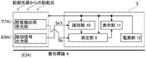
- FIG. 1A is a circuit block diagram showing an outline of a phosphorescent luminance measuring apparatus according to an embodiment of the present invention, and is an explanatory diagram showing a state in which visible light from a phosphorescent marker is measured.
- FIG. 1B is a circuit block diagram showing an outline of a luminous intensity measurement apparatus according to an embodiment of the present invention, and is an explanatory diagram showing a state in which excitation light from an excitation light source is measured.
- 2A is a circuit block diagram showing another example of the excitation intensity detection light receiving case shown in FIG. 1B, in which the illuminance detection light reception case having the illuminance detection light receiving section is connected to the measuring instrument main body case shown in FIG. 1B.
- FIG. 1A is a circuit block diagram showing an outline of a phosphorescent luminance measuring apparatus according to an embodiment of the present invention, and is an explanatory diagram showing a state in which visible light from a phosphorescent marker is measured.
- FIG. 1B is a circuit block
- FIG. 2B is a circuit block diagram showing another example of the excitation intensity detection light receiving case shown in FIG. 1B, and the ultraviolet intensity detection light receiving case having the ultraviolet intensity detection light receiving section is formed in the measuring instrument main body case shown in FIG. 1B. It is explanatory drawing which shows the state connected.
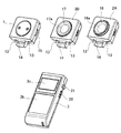
- FIG. 3 is a perspective view showing the appearance of a light receiving case for detecting afterglow luminance, a light receiving case for detecting illuminance, a light receiving case for detecting UV intensity, and a measuring instrument main body case.
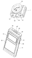
- FIG. 4 is a perspective view showing a state in which the afterglow luminance detection light receiving case attached to the measuring device main body case is turned over and visually observed.
- FIG. 3 is a perspective view showing the appearance of a light receiving case for detecting afterglow luminance, a light receiving case for detecting illuminance, a light receiving case for detecting UV intensity, and a measuring instrument main body case.
- FIG. 4 is a perspective view showing a state in which the after
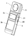
- FIG. 5 is a perspective view showing a state in which the afterglow luminance detection light receiving case is attached to the measuring instrument main body case shown in FIG.
- FIG. 6 is a perspective view showing a state in which the phosphorescent luminance measuring apparatus shown in FIG.
- FIG. 7 is a cross-sectional view of the phosphorescent luminance measuring apparatus shown in FIGS. 5 and 6, and is a cross-sectional view in which electric circuit elements are omitted.
- FIG. 8 is a plan view of the luminous intensity measurement apparatus shown in FIG.
- FIG. 9 is a side view of the luminous intensity measurement apparatus shown in FIG. FIG.
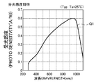
- FIG. 10A is a characteristic diagram for explaining the relationship between the spectral characteristics of the filter installed in the afterglow luminance detection light receiving case, the light receiving sensitivity characteristic of the light receiving element, and the standard relative luminous sensitivity, and the sensitivity curve of the light receiving element.
- FIG. 10B is a characteristic diagram for explaining the relationship between the spectral characteristics of the filter installed in the light receiving case for detecting the afterglow luminance and the light receiving sensitivity characteristics of the light receiving element and the standard relative luminous sensitivity. It is a figure which shows a rate curve.
- FIG. 10A is a characteristic diagram for explaining the relationship between the spectral characteristics of the filter installed in the afterglow luminance detection light receiving case, the light receiving sensitivity characteristic of the light receiving element, and the standard relative luminous sensitivity, and the sensitivity curve of the light receiving element.
- FIG. 10B is a characteristic diagram for explaining the relationship between the spectral characteristics of the filter installed in the light receiving case for detecting the afterglow luminance and the light receiving sensitivity characteristics
- FIG. 10C is a characteristic diagram for explaining the relationship between the spectral characteristics of the filter installed in the afterglow luminance detection light receiving case, the light receiving sensitivity characteristic of the light receiving element, and the standard relative luminous sensitivity. It is a figure which shows a rate curve.
- FIG. 10D is a characteristic diagram for explaining the relationship between the spectral characteristic of the filter installed in the afterglow luminance detection light receiving case and the light receiving sensitivity characteristic of the light receiving element and the standard relative luminous sensitivity
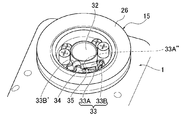
- FIG. FIG. 11 is an explanatory view showing a detailed configuration of the entrance opening shown in FIG. 8, and is a view showing the cover plate shown in FIG. 8 removed.
- 12 is an enlarged view of the mechanical switch member shown in FIG. FIG.
- FIG. 13 is a plan view showing an example of a safety sign as the phosphorescent sign shown in FIGS. 1A, 1B, 2A, and 2B.
- FIG. 14A is an explanatory view showing an example of measurement by the phosphorescent luminance measuring apparatus according to the embodiment of the present invention, and is an explanatory view showing a state where excitation light is irradiated.
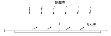
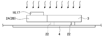
- FIG. 14B is an explanatory diagram showing an example of measurement by the phosphorescent luminance measuring apparatus according to the embodiment of the present invention, and is an explanatory diagram showing a state in which the excitation intensity of the excitation light is being measured.
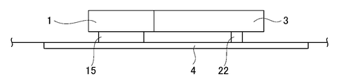
- FIG. 14C is an explanatory diagram showing an example of measurement by the phosphorescent luminance measuring apparatus according to the embodiment of the present invention, and is an explanatory diagram showing a state in which the afterglow luminance is measured.
- FIG. 1A and FIG. 1B are circuit block diagrams showing an outline of a luminous intensity measurement device according to the present invention.
- 1 is a light receiving case for detecting afterglow luminance
- 2 is a light receiving case for detecting excitation intensity
- 3 is a measuring device main body case.
- the afterglow luminance detection light receiving case 1 receives the visible light emitted from the phosphorescent material of the phosphorescent sign 4 and outputs the photoelectric conversion signal Sp, and the identification for outputting the identification signal Sh. And a signal output unit 6.
- the excitation intensity detection light receiving case 2 receives excitation light from an excitation light source that excites a phosphorescent material and outputs a photoelectric conversion signal Sp, and an identification signal output that outputs an identification signal Sh ′. Part 8.
- the light receiving case 1 for detecting afterglow luminance and the light receiving case 2 for detecting excitation intensity are detachably attached to the same measuring device main body case 3 and are electrically connected by a connector portion described later.
- the afterglow luminance detection light receiving unit 5, the excitation intensity detection light receiving unit 7, and the identification signal output units 6 and 8 are supplied with power from, for example, a power supply unit described later.
- the identification signal Sh is composed of, for example, an (H, H) signal
- the identification signal Sh ′ is composed of, for example, an (H, L) signal.
- the measuring instrument main body case 3 includes a measuring unit 9, an identifying unit 10, a display unit 11, and a power supply unit 12.
- a battery is used as the power supply of the power supply unit 12.
- the power supply unit 12 supplies power to the measurement unit 9, the identification unit 10, the display unit 11, the afterglow luminance detection light receiving case 1, and the excitation intensity detection light reception case 2.
- the identification unit 10 receives the identification signals Sh and Sh ′, and recognizes which of the afterglow luminance detection light receiving case 1 and the excitation intensity detection light receiving case 2 is connected to the measuring device main body case 3. Fulfills the function.
- the measurement unit 9 includes an afterglow luminance measurement unit and an excitation intensity measurement unit.
- the afterglow luminance measuring unit has a function of calculating the afterglow luminance by performing calculation according to the afterglow luminance calculation program when the photoelectric conversion signal Sp from the afterglow luminance detecting light receiving unit 5 is input.
- the excitation intensity measurement unit has a function of calculating the excitation intensity by performing calculation according to the excitation intensity calculation program.
- the identification unit 10 switches the measurement unit 9 to a state of calculating according to the afterglow luminance calculation program. Further, when the excitation intensity detection light receiving case 2 is attached to the measuring device main body case 3, the identification unit 10 switches the measurement unit 9 to a state in which the measurement unit 9 is operated according to the excitation intensity calculation program.
- the light receiving case 2 for detecting excitation intensity may be a light receiving case 2A for detecting illuminance as shown in FIG. 2A, or a light receiving case 2B for detecting ultraviolet intensity as shown in FIG. 2B.
- the illuminance detection light receiving case 2A includes an illuminance detection light receiving unit 7A that receives illumination light as excitation light and outputs a photoelectric conversion signal Sp, and an identification signal output unit 8A.
- the ultraviolet intensity detection light receiving case 2B includes an ultraviolet intensity detection light receiving unit 7B that receives ultraviolet light as excitation light and outputs a photoelectric conversion signal Sp, and an identification signal output unit 8B.
- the identification signal output unit 8A outputs the identification signal Sh'1, and the identification signal output unit 8B outputs the identification signal Sh'2.
- the identification signal Sh′1 is composed of, for example, an (L, H) signal
- the identification signal Sh′2 is composed of, for example, an (L, L) signal.
- the identification unit 10 switches the measurement unit 9 to a state of calculating according to the illuminance calculation program when the illuminance detection light receiving case 2A is attached to the measuring device main body case 3. Further, when the UV intensity detection light receiving case 2B is attached to the measuring device main body case 3, the discriminator 10 switches the measuring unit 9 to a state of calculating according to the UV intensity calculation program.
- FIG. 3 shows an exploded perspective view of the luminous intensity measuring device.
- the afterglow luminance detecting light receiving case 1, the illuminance detecting light receiving case 2A, and the ultraviolet intensity detecting light receiving case 2B have a pair of positioning pins 13 having the same shape and a connector portion 14 having the same shape.
- the connector portion 14 is formed with a guide protrusion 14 '(see FIG. 4) extending in the insertion direction, a power supply terminal (not shown), and an input / output signal terminal.
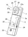
- the afterglow luminance detection light-receiving portion 5 has a cylindrical incident opening 15 that protrudes from the outer surface of the afterglow luminance detection light-receiving case 1 and receives phosphorescence as visible light. Details of the incident opening 15 will be described later.
- the illuminance detection light receiving portion 7A (see FIG. 2A) has an annular incident opening 16 that projects from the outer surface of the illuminance detection light receiving case 2A and into which illumination light as visible light enters.
- the ultraviolet intensity detecting light receiving portion 7B (see FIG. 2B) has an annular incident opening 17 that protrudes from the outer surface of the ultraviolet intensity detecting light receiving case 2B and receives ultraviolet rays.
- reference numerals 16a and 17a indicate incident surfaces.
- the measuring device main body case 3 is provided with a connector portion 18 corresponding to the connector portion 14 as shown in FIG.
- the connector portion 18 is formed with a guide groove 18 'corresponding to the guide protrusion 14'.
- the measuring instrument main body case 3 is formed with fitting holes 19 on both sides of the connector portion 18 for fitting the pair of positioning pins 13.
- a power switch 20 and a prediction switch 21 are provided on the side surface of the measuring instrument main body case 3.
- the power switch 20 When the power switch 20 is turned on, power is supplied to the measurement unit 9, the identification unit 10, and the display unit 11. As a result, the measuring instrument main body case 3 becomes ready for measurement, and power is supplied to the light receiving case for detection attached to the measuring instrument main body case 3.
- the prediction switch 21 is used when measuring the afterglow luminance, but since it is not directly related to the present invention, the description thereof is omitted.
- FIG. 5 shows a state in which the afterglow luminance detection light receiving case 1 is attached to the measuring device main body case 3.
- the measuring instrument body case 3 has an outer surface on the side where the incident opening 15 faces the phosphorescent sign 4 when the afterglow luminance detection light receiving case 1 is attached to the measuring instrument body case 3.
- a pair of leg portions 22 projecting from the outer surface 3a is formed on the outer surface 3a on the same side as the outer surface 3a.
- Reference numeral 23 denotes a battery lid 23.
- the protruding height H of the pair of leg portions 22 from the outer surface 3a is substantially the same as the protruding height from the outer surface of the incident opening 15 as shown in FIG. Thereby, when the phosphorescence luminance measuring device is placed on the phosphorescent marker 4 and the afterglow luminance is measured, the parallelism of the phosphorescent luminance measuring device with respect to the phosphorescent marker 4 is maintained.
- an AC power supply adapter terminal 24 is provided on the side surface of the measuring instrument main body case 3 opposite to the side surface on which the power switch 20 is installed, as shown in FIG.
- a display surface 3c that constitutes a part of the display unit 11 and displays the measurement result of the measuring unit 9 is displayed. Is provided.
- the display surface 3c has ring-shaped incident openings 16 and 17 when the light receiving case 2 for detecting excitation intensity (light receiving case 2A for detecting illuminance, light receiving case 2B for detecting ultraviolet intensity) is attached to the measuring instrument main body case 3. It is provided on the outer surface 3 b on the side protruding from the main body case 3. Therefore, the illuminance measurement result can be visually confirmed during the illuminance measurement, and the ultraviolet intensity can be visually confirmed during the measurement of the ultraviolet intensity.
- the display surface 3c is provided on the outer surface 3b opposite to the outer surface 3a on the side from which the incident opening 15 protrudes when the afterglow luminance detection light receiving case 1 is attached to the measuring device main body case 3. Therefore, the measurement result can be visually confirmed during the afterglow luminance measurement.
- the structures of the illuminance detection light-receiving unit 7A and the ultraviolet intensity detection light-receiving unit 7B can be dealt with by reducing the size of a known structure, and a detailed description thereof will be omitted.
- a detailed configuration of the afterglow luminance detection light receiving unit 5 will be described.
- the incident opening 15 includes a black annular cushion member 26 and a black lid plate 27.
- the lid plate 27 is fixed to the incident opening 15 by a screw member 27a. As shown in FIG. 8, circular openings 28 and 29 are formed in the lid plate 27.
- the reason why the cushion member 26 and the cover plate 27 are black is to prevent reflection as much as possible.
- the cushion member 26 protrudes slightly outward from the lid plate 27 in consideration of the contraction. Thereby, it is possible to prevent scattered light from entering the afterglow luminance detecting light receiving unit 5 during the afterglow luminance measurement.
- a silicon photodiode 30 as a light receiving element, a first filter 31, and a second filter 32 are arranged inside the incident opening 15 from the inner part toward the circular opening 28. It is arranged.
- the silicon photodiode 30 has a sensitivity curve Q1 shown in FIG. 10A with respect to the wavelength of light.
- the first filter 31 has a transmittance curve Q2 shown in FIG. 10B, and the second filter 32 has a transmittance curve Q3 shown in FIG. 10C.
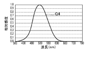
- the first filter 31 and the second filter 32 are configured so that light having a wavelength distribution approximate to the human standard relative luminous sensitivity curve Q4 shown in FIG.
- the second filter 32 is also used to suppress the output of the photoelectric conversion signal Sp on the long wavelength side of the silicon photodiode 30.
- the mechanical measurement start switch member 33 includes a leaf spring 33A and a leaf spring 33B.
- the leaf spring 33A is fixed to the top of the microswitch member 34 and has an inclined piece portion 33A ′ and a semi-cylindrical engaging convex portion 33A ′′.
- the inclined piece portion 33A ′ is bent.
- the leaf spring 33B has a semicircular curved portion 33B ′, which projects outward from the circular opening 29 as shown in FIGS.
- the inclined piece 33A ' is in contact with the actuator 35 of the microswitch member 34.
- the inclined piece portion 33A ' is used to secure the advance stroke of the actuator 35 of the microswitch member 34.
- the microswitch member 34 is turned on when the semicircular curved portion 33B 'is brought into contact with, for example, a safety sign (see FIG. 13) as the phosphorescent sign 4 and pushed into the entrance opening 15.
- the afterglow luminance detection light receiving unit 5 When the power switch 20 is turned on, the afterglow luminance detection light receiving unit 5 outputs the photoelectric conversion signal Sp toward the measurement unit 9 at regular time intervals.
- the microswitch member 34 When the microswitch member 34 is turned on, the measurement unit 9 starts measuring the afterglow luminance using the photoelectric conversion signal Sp input to the measurement unit 9.
- the reason why the measurement of the afterglow luminance is made mechanical will be described later, and the method of using this phosphorescence luminance measuring device will be described first.
- the phosphorescent sign (safety sign) 4 is usually irradiated with ultraviolet light or visible light as excitation light by a fluorescent lamp or sunlight. In the dark due to a power failure or the like, phosphorescence is emitted as visible light from the portion where the phosphorescent material 4 ′ is applied.
- the measurement device main body case 3 is equipped with a light receiving case 2A for detecting illuminance or a light receiving case 2B for detecting ultraviolet intensity.
- a light receiving case 2A for detecting illuminance
- a light receiving case 2B for detecting ultraviolet intensity.
- the posture of the phosphorescent luminance measuring device exposed to light can be kept the same as the posture of the phosphorescent marker 4, so that the excitation intensity can be measured under conditions closer to the actual environmental conditions. Can be done with.
- the afterglow luminance detection light receiving case 1 When measuring the afterglow luminance, as shown in FIG. 14C, the afterglow luminance detection light receiving case 1 is attached to the measuring device main body case 3 and set to the phosphorescent sign 4. Then, the semicircular curved portion 33B ′ comes into contact with the phosphorescent marker 4, and the microswitch member 34 is turned on. Thereby, the measurement part 9 starts the measurement of an afterglow brightness
- the measurement unit 9 calculates the afterglow luminance based on the photoelectric conversion signal Sp, and the calculation result is displayed on the display unit 11. Although the afterglow luminance decreases with the passage of time, the measurement unit 9 displays the measurement value of the afterglow luminance every moment.
- microswitch member 34 since the microswitch member 34 is automatically turned on simultaneously with the contact with the phosphorescent sign 4 to start the measurement of afterglow luminance, a time lag due to an artificial operation error can be prevented.
- microswitch member 34 is not turned on unless the phosphorescent sign 4 is touched, it is possible to improve the reliability of the measurement accuracy of the afterglow luminance.
Landscapes
- Physics & Mathematics (AREA)
- General Physics & Mathematics (AREA)
- Spectroscopy & Molecular Physics (AREA)
- Photometry And Measurement Of Optical Pulse Characteristics (AREA)
- Investigating, Analyzing Materials By Fluorescence Or Luminescence (AREA)
- Testing Of Optical Devices Or Fibers (AREA)
Description
本発明は、残光輝度を測定することのできる蓄光輝度測定器に関する。
従来から、蓄光性材料を用いて安全に対する警告、指示等の情報を伝達する安全標識板が知られている。この種の安全標識板は、合成樹脂製、陶器製、或いはガラス製等の基板の表面に、蓄光性材料を塗布加工等すると共に、色材料によって安全に対する警告等の情報をデザイン化することにより構成されている(例えば、特許文献1参照。)。
ところで、蓄光性材料は、太陽光、蛍光等の光を吸収してそのエネルギーを蓄積し、この蓄積されたエネルギーを可視光として放出する物理特性を有する。その蓄光性材料は、暗闇になったときでも残光としてのリン光を発生するので、その安全標識板は、暗闇の中でも、蓄光性材料から発せられるリン光により安全標識を認識できる。
その蓄光性材料から発せられるリン光は、時間の経過と共に減衰する減衰特性を有する。蓄光性材料には、アルミニウム酸ストロンチウム、アルミン酸カルシウム、硫化亜鉛等が知られている。
暗所で安全標識として機能させるためには、所要時間が経過したときの安全標識板のリン光の輝度が所定値以上であることが要求される。例えば、蓄光性材料を用いて安全に対する警告、指示等の情報を伝達する安全標識板の場合、安全標識板に光を所定時間、所定強度で照射して、20分経過後の残光輝度としてのリン光輝度が24mcd/m2(24ミリカンデラ/m2)であることが要求される。
ところで、この種の安全標識の残光輝度を測定する測定器として、スポットメータのような輝度測定器が用いられている。この種の安全標識の残光輝度の測定は、例えば、以下に説明する手順により行われる。
まず、この種の安全標識を暗所に数時間保管してリン光輝度を減衰させる。
まず、この種の安全標識を暗所に数時間保管してリン光輝度を減衰させる。
その後、所定の照度の光を所定の時間照射して、蓄光性材料に光エネルギーを蓄積させる。
ついで、その蓄光性材料に光エネルギーが蓄積された安全標識を暗所に再び置いて、輝度計により残光輝度としてのリン光の輝度を測定する。
ついで、その蓄光性材料に光エネルギーが蓄積された安全標識を暗所に再び置いて、輝度計により残光輝度としてのリン光の輝度を測定する。
例えば、JIS(日本工業規格)では、その標識板の残光輝度を測定するために、所定の照度の光を所定の時間照射する励起光源として、常用光源蛍光ランプD65を用いることが規定されている。
ところが、励起光源には、蛍光灯の他、電球、発光ダイオード(LED)、ハロゲンランプなどがある。これらの光源はその色温度特性(発光スペクトル)が異なるため、照度(ルクス(lx))が同じであっても、その標識板の所定時間経過後の残光輝度が異なることが、研究によって明らかになりつつある。
すなわち、蓄光性材料を励起する励起波長は、蓄光性材料の物理特性によって異なり、紫外線ないし紫色の光の波長(波長250nmないし450nm)の範囲である。このため、照度だけを基準として安全標識の残光輝度を評価するのは好ましくない。
すなわち、蓄光標識の輝度の評価を正確に精度良く測定するには、照度測定器と、紫外線強度測定器と、蓄光輝度測定器との三種類の測定器が必要となる。
ところが、蓄光標識の輝度を測定するのに、携帯型の三種類の測定器を現地に持参するのは、携帯型とは言っても不便である。また、測定器のコストもかかる。
ところが、蓄光標識の輝度を測定するのに、携帯型の三種類の測定器を現地に持参するのは、携帯型とは言っても不便である。また、測定器のコストもかかる。
本発明は、上記の事情に鑑みて為されたもので、一台の測定器で、蓄光輝度と、励起強度としての照度と、紫外線強度との測定を行うことが可能な蓄光輝度測定器を提供することを目的とする。
本発明に係る蓄光輝度測定器は、残光輝度検出用受光部を有する残光輝度検出用受光ケースと、励起強度検出用受光部を有する励起強度検出用受光ケースと、残光輝度検出用受光ケースと励起強度検出用受光ケースとが着脱可能に電気的に接続され、かつ、各光電変換信号によって残光輝度と励起強度とを演算して測定する測定部とを有する測定器本体ケースとを備えている。
残光輝度検出用受光ケースと、励起強度検出用受光ケースとは、これらを互いに識別するための識別信号を出力する識別信号出力部を有する。
測定器本体ケースは、識別信号が入力されて測定器本体ケースに残光輝度検出用受光ケースと励起強度検出用受光ケースとのいずれが接続されたか否かを認識する識別部を有する。
測定器本体ケースは、識別信号が入力されて測定器本体ケースに残光輝度検出用受光ケースと励起強度検出用受光ケースとのいずれが接続されたか否かを認識する識別部を有する。
測定部は、識別部の認識状態に応じて残光輝度を演算する状態と励起強度を演算する状態との間で切り替えられる。
本発明によれば、測定器用本体ケースに残光輝度検出用受光ケースが接続されたときには、残光輝度を測定できる。測定器用本体ケースに励起強度用検出用ケースが装着されたときには、励起用強度の測定を行うことができる。従って、一台の測定器で、蓄光輝度と、励起強度としての照度と、紫外線強度との測定を行うことができることになり、便利である。
以下に、本発明に係る蓄光輝度測定装置の実施例を添付図面を参照しつつ説明する。
図1A、図1Bは、本発明に係る蓄光輝度測定装置の概要を示す回路ブロック図である。
その図1A、図1Bにおいて、1は残光輝度検出用受光ケース、2は励起強度検出用受光ケース、3は測定器本体ケースである。
図1A、図1Bは、本発明に係る蓄光輝度測定装置の概要を示す回路ブロック図である。
その図1A、図1Bにおいて、1は残光輝度検出用受光ケース、2は励起強度検出用受光ケース、3は測定器本体ケースである。
残光輝度検出用受光ケース1は、蓄光標識4の蓄光材料から放射される可視光を受光して光電変換信号Spを出力する残光輝度検出用受光部5と、識別信号Shを出力する識別信号出力部6とを有する。
励起強度検出用受光ケース2は、蓄光材料を励起する励起光源からの励起光を受光して光電変換信号Spを出力する励起強度検出用受光部7と、識別信号Sh’を出力する識別信号出力部8とを有する。
残光輝度検出用受光ケース1と励起強度検出用受光ケース2とは同一の測定器本体ケース3に着脱可能とされて、後述するコネクタ部により電気的に接続される。その残光輝度検出用受光部5、励起強度検出用受光部7、識別信号出力部6、8には、例えば、後述する電源部から電源電力が供給される。
識別信号Shは、例えば、(H、H)信号から構成され、識別信号Sh’は、例えば、(H、L)信号から構成されている。これにより、残光輝度検出用受光ケース1が測定器本体ケース3に接続されたか、励起強度検出用受光ケース2が測定器本体ケース3に接続されたかが区別される。
測定器本体ケース3は、測定部9と、識別部10と、表示部11と、電源部12とを有する。電源部12の電源には、例えば、電池が用いられる。その電源部12は、測定部9、識別部10、表示部11、残光輝度検出用受光ケース1、励起強度検出用受光ケース2に電力を供給する。
識別部10は、識別信号Sh、Sh’が入力されて、測定器本体ケース3に残光輝度検出用受光ケース1と励起強度検出用受光ケース2とのいずれが接続されたか否かを認識する機能を果たす。
測定部9は、残光輝度測定部と励起強度測定部とを備えている。残光輝度測定部は残光輝度検出用受光部5からの光電変換信号Spが入力されると残光輝度演算プログラムに従って演算を行って残光輝度を求める機能を有する。励起強度測定部は励起強度検出用受光部7から光電変換信号Spが入力されると励起強度演算プログラムに従って演算を行って励起強度を求める機能を有する。
識別部10は、残光輝度検出用受光ケース1が測定器本体ケース3に装着されたときには、測定部9を残光輝度演算プログラムに従って演算する状態に切り替える。また、識別部10は、励起強度検出用受光ケース2が測定器本体ケース3に装着されたときには、測定部9を励起強度演算プログラムに従って演算する状態に切り替える。
励起強度検出用受光ケース2は、図2Aに示すように、照度検出用受光ケース2Aであっても良いし、図2Bに示すように、紫外線強度検出用受光ケース2Bであっても良い。
照度検出用受光ケース2Aは、励起光としての照明光を受光して光電変換信号Spを出力する照度検出用受光部7Aと、識別信号出力部8Aとを有する。
紫外線強度検出用受光ケース2Bは、励起光としての紫外線を受光して光電変換信号Spを出力する紫外線強度検出用受光部7Bと、識別信号出力部8Bとを有する。
紫外線強度検出用受光ケース2Bは、励起光としての紫外線を受光して光電変換信号Spを出力する紫外線強度検出用受光部7Bと、識別信号出力部8Bとを有する。
識別信号出力部8Aは識別信号Sh’1を出力し、識別信号出力部8Bは識別信号Sh’2を出力する。識別信号Sh’1は、例えば、(L、H)信号から構成され、識別信号Sh’2は、例えば、(L、L)信号から構成されている。これらのハイレベルと、ローレベルの信号の組み合わせによって、残光輝度検出用受光ケース1と照度検出用受光ケース2Aと紫外線強度検出用受光ケース2Bとのいずれが測定器本体ケース3に接続されたか否かが区別される。
識別部10は、照度検出用受光ケース2Aが測定器本体ケース3に装着されたときには、測定部9を照度演算プログラムに従って演算する状態に切り替える。また、識別器10は、紫外線強度検出用受光ケース2Bが測定器本体ケース3に装着されたときには、測定部9を紫外線強度演算プログラムに従って演算する状態に切り替える。
(残光輝度検出用受光ケース1と照度検出用受光ケース2Aと紫外線強度検出用受光ケース2Bと測定器本体ケース3の外観構成)
図3は蓄光輝度測定器の分解斜視図を示している。
図3は蓄光輝度測定器の分解斜視図を示している。
残光輝度検出用受光ケース1、照度検出用受光ケース2A、紫外線強度検出用受光ケース2Bは、同一形状の一対の位置決めピン13と、同一形状のコネクタ部14とを有する。コネクタ部14には挿入方向に延びる案内突起14’(図4参照)と図示を略す電力供給端子、入出力信号端子とが形成されている。
残光輝度検出用受光部5は、図4に示すように、残光輝度検出用受光ケース1の外面から突出されて可視光としてのりん光が入射する円柱形状の入射開口部15を有する。この入射開口部15の詳細については後述する。
照度検出用受光部7A(図2A参照)は、図3に示すように、照度検出用受光ケース2Aの外面から突出されて可視光としての照明光が入射する輪環状入射開口部16を有する。紫外線強度検出用受光部7B(図2B参照)は、紫外線強度検出用受光ケース2Bの外面から突出されて、紫外線が入射する輪環状入射開口部17を有する。その図3において、符合16a、17aは入射面を示している。
測定器本体ケース3には、図4に示すように、コネクタ部14に対応するコネクタ部18が設けられている。このコネクタ部18には案内突起14’に対応する案内溝18’が形成されている。また、測定器本体ケース3には、コネクタ部18を挟んでその両側に一対の位置決めピン13が嵌合する嵌合穴19が形成されている。その測定器本体ケース3の側面には、図3、図4に示すように、電源スイッチ20と、予測スイッチ21とが設けられている。
電源スイッチ20をオンすると、測定部9と、識別部10と、表示部11とに電力が供給される。これにより、測定器本体ケース3が測定可能状態となると共に、測定器本体ケース3に装着された検出用受光ケースに電力が供給される。予測スイッチ21は、残光輝度測定の際に用いられるものであるが、この発明に直接的に関連しないので、その説明は省略する。
図5は測定器本体ケース3に残光輝度検出用受光ケース1が装着された状態が示されている。その測定器本体ケース3には、図6に示すように、この測定器本体ケース3に残光輝度検出用受光ケース1を装着したときに、入射開口部15が蓄光標識4に臨む側の外面と同一側の外面3aにこの外面3aから突出する一対の脚部22が形成されている。なお、符号23は電池蓋23を示す。
その一対の脚部22の外面3aからの突出高さHは、図7に示すように、入射開口部15の外面からの突出高さと略同じ高さとされている。これにより、蓄光輝度測定器を蓄光標識4に置いて、残光輝度を測定するときに、蓄光標識4に対する蓄光輝度測定器の平行性が保たれる。なお、その測定器本体ケース3の電源スイッチ20が設置されている側面と反対側の側面には、図6に示すようにAC電源供給用アダプタ端子24が設けられている。
その測定器本体ケース3の外面3aと反対側の外面3bには、図3ないし図5に示すように、表示部11の一部を構成しかつ測定部9の測定結果を表示する表示面3cが設けられている。
測定器本体ケース3に励起強度検出用受光ケース2(照度検出用受光ケース2A、紫外線強度検出用受光ケース2B)を装着したときの測定器本体ケース3の外面3bからの輪環状入射開口部16、17の突出方向は、測定器本体ケース3に残光輝度検出用受光ケース1を装着したときの測定器本体ケース3の外面3aからの入射開口部15の突出方向に対して逆向きにされている。
表示面3cは、測定器本体ケース3に励起強度検出用受光ケース2(照度検出用受光ケース2A、紫外線強度検出用受光ケース2B)を装着したときに輪環状入射開口部16、17が測定器本体ケース3から突出する側の外面3bに設けられている。従って、照度測定中には、照度の測定結果を目視確認でき、紫外線強度を測定中には、紫外線強度を目視確認できる。
また、表示面3cは、測定器本体ケース3に残光輝度検出用受光ケース1を装着したときには、入射開口部15が突出する側の外面3aに対して反対側の外面3bに設けられているので、残光輝度測定中もその測定結果を目視確認できる。
照度検出用受光部7A、紫外線強度検出用受光部7Bの構造には、公知の構造のものを小型化することによって対処できるので、その詳細な説明は省略する。
以下、残光輝度検出用受光部5の詳細構成について説明する。
以下、残光輝度検出用受光部5の詳細構成について説明する。
(残光輝度検出用受光部5、入射開口部15の構造)
入射開口部15は、黒色の環状のクッション部材26と、黒色の蓋板27とを有する。蓋板27はネジ部材27aにより入射開口部15に固定されている。その蓋板27には、図8に示すように、円形開口28、29が形成されている。クッション部材26、蓋板27を黒色にしたのは、反射を極力防止するためである。クッション部材26はその縮み分を考慮して蓋板27よりも若干外側に向かって突出されている。これにより、残光輝度測定の際に、残光輝度検出用受光部5に散乱光が入射するのを防止できる。
入射開口部15は、黒色の環状のクッション部材26と、黒色の蓋板27とを有する。蓋板27はネジ部材27aにより入射開口部15に固定されている。その蓋板27には、図8に示すように、円形開口28、29が形成されている。クッション部材26、蓋板27を黒色にしたのは、反射を極力防止するためである。クッション部材26はその縮み分を考慮して蓋板27よりも若干外側に向かって突出されている。これにより、残光輝度測定の際に、残光輝度検出用受光部5に散乱光が入射するのを防止できる。
その入射開口部15の内部には、図6、図7に示すように、その奥部から円形開口28に向かって、受光素子としてのシリコンフォトダイオード30、第1フィルタ31、第2フィルタ32が配設されている。
シリコンフォトダイオード30は、光の波長に対して図10Aに示す感度曲線Q1を有している。第1フィルタ31は、図10Bに示す透過率曲線Q2を有し、第2フィルタ32は図10Cに示す透過率曲線Q3を有する。第1フィルタ31と第2フィルタ32とにより図10Dに示す人間の標準比視感度曲線Q4に近似した波長分布の光がシリコンフォトダイオード30に入射する構成とされている。なお、第2フィルタ32は、シリコンフォトダイオード30の長波長側の光電変換信号Spの出力を抑制するのにも用いられる。
その入射開口部15の内部には、図11に拡大して示すように、機械式測定開始スイッチ部材33と、マイクロスイッチ部材34とが設けられている。機械式測定開始スイッチ部材33は、板バネ33Aと板バネ33Bとから構成されている。
板バネ33Aは、図12に示すように、マイクロスイッチ部材34の頂部に固定されて、傾斜片部33A’と半円柱状係合凸部33A”とを有する。その傾斜片部33A’は撓むようにされている。板バネ33Bは半円状湾曲部33B’を有する。この半円状湾曲部33B’は、図8、図9に示すように、円形開口29から外部に突出している。
その傾斜片部33A’は、マイクロスイッチ部材34のアクチュエータ35に当接されている。その傾斜片部33A’はマイクロスイッチ部材34のアクチュエータ35の進出ストロークを確保するのに用いられる。
そのマイクロスイッチ部材34は、半円状湾曲部33B’が蓄光標識4としての例えば安全標識(図13参照)に接触されて、入射開口部15の内部に押し込まれると、オンされる。
残光輝度検出用受光部5は、電源スイッチ20がオンされると、一定時間間隔で光電変換信号Spを測定部9に向けて出力する。そのマイクロスイッチ部材34がオンされると、測定部9は、この測定部9に入力された光電変換信号Spを用いて残光輝度の測定を開始する。
ここで、残光輝度の測定開始を機械式にした理由は、後述することとし、先にこの蓄光輝度測定器の使用方法を説明する。
ここで、残光輝度の測定開始を機械式にした理由は、後述することとし、先にこの蓄光輝度測定器の使用方法を説明する。
蓄光標識(安全標識)4には、通常、蛍光灯や太陽光により、図14Aに示すように、励起光としての紫外光や可視光が照射されている。停電等により、暗闇になると、蓄光材料4’が塗布された部分から可視光としてりん光が放射される。
そこで、紫外光や可視光等の励起光の励起強度を測定するときには、図14Bに示すように、測定器本体ケース3に照度検出用受光ケース2A又は紫外線強度検出用受光ケース2Bを装着して蓄光標識4にセットする。この場合、蓄光標識4に対して蓄光輝度測定器が平行となるように、一対の脚部22を二組設けるのが望ましい。一対の脚部22を二組設けると、光に曝される蓄光輝度測定器の姿勢を蓄光標識4の姿勢と同じに保つことができるので、励起強度の測定を実際の環境条件により近い条件のもとで行うことができる。
このように一対の脚部22を二組設けると、輪環状入射開口部16、17に垂直方向から入射する紫外光や可視光を均一に受光部に取り込むことができることとなって便利だからである。
残光輝度を測定するときには、図14Cに示すように、測定器本体ケース3に残光輝度検出用受光ケース1を装着して、蓄光標識4にセットする。
すると、半円状湾曲部33B’が蓄光標識4に接触して、マイクロスイッチ部材34がオンされる。これにより、測定部9は光電変換信号Spを用いて残光輝度の測定を開始する。
すると、半円状湾曲部33B’が蓄光標識4に接触して、マイクロスイッチ部材34がオンされる。これにより、測定部9は光電変換信号Spを用いて残光輝度の測定を開始する。
残光輝度測定器は、蓄光標識4に平行であるので、円形開口28には、受光素子の入射面に対して略垂直方向からりん光が入射する。測定部9は、その光電変換信号Spに基づいて残光輝度を演算し、その演算結果が表示部11に表示される。残光輝度は時間の経過と共に減少するが、測定部9は、その時々刻々とその残光輝度の測定値を表示する。
(機械式測定開始スイッチ部材33を用いて残光輝度の測定を開始させることとした理由)
機械式測定開始スイッチ部材33を用いる代わりに、例えば、光スイッチを用いた場合、蓄光標識4の基材がガラスや反射率の高い部材であると、反射光を受光する可能性が大きくなる。その結果、残光輝度の測定開始タイミングにばらつきが生じ、残光輝度の測定が正確にできなくなるからである。
機械式測定開始スイッチ部材33を用いる代わりに、例えば、光スイッチを用いた場合、蓄光標識4の基材がガラスや反射率の高い部材であると、反射光を受光する可能性が大きくなる。その結果、残光輝度の測定開始タイミングにばらつきが生じ、残光輝度の測定が正確にできなくなるからである。
この実施例では、蓄光標識4への接触と同時に自動的にマイクロスイッチ部材34をオンさせて残光輝度の測定開始を実行させているので、人為的操作ミスによるタイムラグを防止できる。
また、蓄光標識4に接触しなければ、マイクロスイッチ部材34がオンしないので、残光輝度の測定精度の確実性を高めることができる。
1…残光輝度検出用受光ケース
2…励起強度検出用受光ケース
3…測定器本体ケース
5…残光輝度検出用受光部
6、8…識別信号出力部
7…励起強度検出用受光部
9…測定部
10…識別部
Sh、Sh’…識別信号
2…励起強度検出用受光ケース
3…測定器本体ケース
5…残光輝度検出用受光部
6、8…識別信号出力部
7…励起強度検出用受光部
9…測定部
10…識別部
Sh、Sh’…識別信号
本出願は、2012年2月1日に日本国特許庁に出願された特願2012-19820に基づいて優先権を主張し、その全ての開示は完全に本明細書で参照により組み込まれる。
Claims (8)
- 蓄光標識の蓄光材料から放射される可視光を受光して光電変換信号を出力する残光輝度検出用受光部を有する残光輝度検出用受光ケースと、
前記蓄光材料を励起する励起光源からの励起光を受光して光電変換信号を出力する励起強度検出用受光部を有する励起強度検出用受光ケースと、
前記残光輝度検出用受光ケースと前記励起強度検出用受光ケースとが着脱可能に電気的に接続され、かつ、前記各光電変換信号によって残光輝度と励起強度とを演算して測定する測定部とを有する測定器本体ケースとを備え、
前記残光輝度検出用受光ケースと前記励起強度検出用受光ケースとはこれらを互いに識別するための識別信号を出力する識別信号出力部を有し、
前記測定器本体ケースは、前記識別信号が入力されて該測定器本体ケースに前記残光輝度検出用受光ケースと前記励起強度検出用受光ケースとのいずれが接続されたか否かを認識する識別部を有し、
前記測定部は、前記識別部により前記残光輝度検出用受光ケースが前記測定器本体ケースに装着されたと判断したときには前記残光輝度を演算する状態に切り替えられ、前記識別部により前記励起強度検出用受光ケースが前記測定器本体ケースに装着されたと判断したときには前記励起強度を演算する状態に切り替えられることを特徴とする蓄光輝度測定器。 - 前記励起強度検出用受光ケースは、照度を検出する照度検出用受光ケースと、紫外線強度を検出する紫外線強度検出用受光ケースとからなり、前記照度検出用受光ケースは、前記励起光としての照明光を受光して前記光電変換信号を出力する照度検出用受光部を有し、前記紫外線強度検出用受光ケースは、前記励起光としての紫外線を受光して前記光電変換信号を出力する紫外線強度検出用受光部を有し、前記識別信号出力部は前記照度検出用受光ケースと前記紫外線強度検出用受光ケースとを識別する識別信号を出力し、前記測定部は、前記照度検出用受光ケースが前記測定器本体ケースに装着されたと判断したときには前記照度を演算する状態に切り替えられ、前記紫外線強度検出用受光ケースが前記測定器本体ケースに装着されたと判断したときには前記紫外線強度を演算する状態に切り替えられることを特徴とする請求項1に記載の蓄光輝度測定器。
- 前記残光輝度検出用受光部は、前記残光輝度検出用受光ケースから突出して前記蓄光標識に臨んで該蓄光標識からの可視光が入射する入射開口部を有していることを特徴とする請求項1又は請求項2に記載の蓄光輝度測定器。
- 前記測定器本体ケースには、該測定器本体ケースに前記残光輝度検出用受光ケースを装着したときに、前記入射開口部が前記蓄光標識に臨む側の外面と同一側の外面に、該外面から突出する一対の脚部が形成され、該一対の脚部は、前記入射開口部の突出高さと略同等の突出高さを有していることを特徴とする請求項3に記載の蓄光輝度測定器。
- 前記励起強度検出用受光部は輪環状入射開口部を有し、前記測定器本体ケースに前記励起強度検出用受光ケースを装着したときの前記測定器本体ケースの外面からの輪環状入射開口部の突出方向は、前記測定器本体ケースに前記残光輝度検出用受光ケースを装着したときの前記測定器本体ケースの外面からの入射開口部の突出方向に対して逆向きにされていることを特徴とする請求項3に記載の蓄光輝度測定器。
- 前記測定器本体ケースには、該測定器本体ケースに前記残光輝度検出用受光ケースを装着したときに、前記入射開口部が前記蓄光標識に臨む側の外面と同一側の外面に、該外面から突出する一対の脚部が二組形成され、該各脚部は、前記外面からの突出高さが同一とされていることを特徴とする請求項3に記載の蓄光輝度測定器。
- 前記測定器本体ケースには、該測定器本体ケースに前記残光輝度検出用受光ケースを装着したときに、前記入射開口部が前記蓄光標識に臨む側の外面と反対側の外面に、前記測定部の測定結果を表示する表示面が設けられていることを特徴とする請求項4ないし請求項6のいずれか1項に記載の蓄光輝度測定器。
- 蓄光標識の蓄光材料から放射される可視光を受光して光電変換信号を出力する残光輝度検出用受光部を有する残光輝度検出用受光ケースと、
前記蓄光材料を照明する照明光源からの照明光を受光して光電変換信号を出力する照度検出用受光部を有する照度検出用受光ケースと、
前記蓄光材料を励起する励起光源からの紫外光を受光して光電変換信号を出力する紫外線強度検出用受光ケースと、
前記残光輝度検出用受光ケースと前記照度検出用受光ケースと前記紫外線強度検出用受光ケースとが着脱可能に電気的に接続され、かつ、前記各光電変換信号によって残光輝度と照度と紫外線強度とを演算して測定する測定部とを有する測定器本体ケースとを有し、
前記残光輝度検出用受光ケースと、前記照度検出用受光ケースと、前記紫外線強度検出用受光ケースとは、これらを互いに識別するための識別信号を出力する識別信号出力部を有し、
前記測定器本体ケースは、前記識別信号が入力されて該測定器本体ケースに前記残光輝度検出用受光ケースと前記照度検出用受光ケースと前記紫外線強度検出用ケースとのいずれかが接続されたか否かを認識する識別部を有し、
前記測定部は、装着された検出用受光ケースに応じて、測定を実行することを特徴とする蓄光輝度測定器。
Applications Claiming Priority (2)
| Application Number | Priority Date | Filing Date | Title |
|---|---|---|---|
| JP2012019820A JP5964065B2 (ja) | 2012-02-01 | 2012-02-01 | 蓄光輝度測定器 |
| JP2012-019820 | 2012-02-01 |
Publications (1)
| Publication Number | Publication Date |
|---|---|
| WO2013115129A1 true WO2013115129A1 (ja) | 2013-08-08 |
Family
ID=48905168
Family Applications (1)
| Application Number | Title | Priority Date | Filing Date |
|---|---|---|---|
| PCT/JP2013/051750 Ceased WO2013115129A1 (ja) | 2012-02-01 | 2013-01-28 | 蓄光輝度測定器 |
Country Status (2)
| Country | Link |
|---|---|
| JP (1) | JP5964065B2 (ja) |
| WO (1) | WO2013115129A1 (ja) |
Cited By (1)
| Publication number | Priority date | Publication date | Assignee | Title |
|---|---|---|---|---|
| JP2015137912A (ja) * | 2014-01-22 | 2015-07-30 | 日置電機株式会社 | 光量測定用センサおよび光量測定装置 |
Citations (5)
| Publication number | Priority date | Publication date | Assignee | Title |
|---|---|---|---|---|
| JPH09145473A (ja) * | 1995-11-29 | 1997-06-06 | Ushio Inc | 照度測定装置 |
| JPH11238680A (ja) * | 1998-02-20 | 1999-08-31 | Nikon Corp | 露光装置用照度計、リソグラフィ・システム、照度計の較正方法およびマイクロデバイスの製造方法 |
| JP2000283840A (ja) * | 1999-03-31 | 2000-10-13 | Minolta Co Ltd | 測光機器 |
| JP2008151776A (ja) * | 2006-11-21 | 2008-07-03 | Produce:Kk | 輝度測定器および輝度測定方法 |
| JP2010091509A (ja) * | 2008-10-10 | 2010-04-22 | Konica Minolta Sensing Inc | 光学特性測定装置 |
-
2012
- 2012-02-01 JP JP2012019820A patent/JP5964065B2/ja not_active Expired - Fee Related
-
2013
- 2013-01-28 WO PCT/JP2013/051750 patent/WO2013115129A1/ja not_active Ceased
Patent Citations (5)
| Publication number | Priority date | Publication date | Assignee | Title |
|---|---|---|---|---|
| JPH09145473A (ja) * | 1995-11-29 | 1997-06-06 | Ushio Inc | 照度測定装置 |
| JPH11238680A (ja) * | 1998-02-20 | 1999-08-31 | Nikon Corp | 露光装置用照度計、リソグラフィ・システム、照度計の較正方法およびマイクロデバイスの製造方法 |
| JP2000283840A (ja) * | 1999-03-31 | 2000-10-13 | Minolta Co Ltd | 測光機器 |
| JP2008151776A (ja) * | 2006-11-21 | 2008-07-03 | Produce:Kk | 輝度測定器および輝度測定方法 |
| JP2010091509A (ja) * | 2008-10-10 | 2010-04-22 | Konica Minolta Sensing Inc | 光学特性測定装置 |
Non-Patent Citations (1)
| Title |
|---|
| SHOBOCHO YOBO KACHO: "Chikukoshiki Yudo Hyoshiki Nado ni Kakaru Un'yo ni Tsuite (Tsuchi)", 9 April 2010 (2010-04-09), Retrieved from the Internet <URL:http://www.fdma.go.jp/html/data/tuchi2204/pdf/220409yo177.pdf> [retrieved on 20130219] * |
Cited By (1)
| Publication number | Priority date | Publication date | Assignee | Title |
|---|---|---|---|---|
| JP2015137912A (ja) * | 2014-01-22 | 2015-07-30 | 日置電機株式会社 | 光量測定用センサおよび光量測定装置 |
Also Published As
| Publication number | Publication date |
|---|---|
| JP2013160512A (ja) | 2013-08-19 |
| JP5964065B2 (ja) | 2016-08-03 |
Similar Documents
| Publication | Publication Date | Title |
|---|---|---|
| EA008454B1 (ru) | Способ и устройство для определения подлинности документов и товаров | |
| KR101091791B1 (ko) | 적분구 광도계 및 그 측정 방법 | |
| US12281958B2 (en) | Optical power detector and reader | |
| NO20076532L (no) | Fremgangsmate og apparat for a male lysstyrken til et lysemitterende legeme | |
| JP2009115797A (ja) | 光測定装置 | |
| WO2005067566A3 (en) | Fluorescence measuring device for gemstones | |
| JP2012215569A (ja) | 携帯型色計測デバイス | |
| JP2008151776A (ja) | 輝度測定器および輝度測定方法 | |
| JP5964065B2 (ja) | 蓄光輝度測定器 | |
| JP5863486B2 (ja) | 蓄光輝度測定器 | |
| WO2019127548A1 (zh) | 混光装置、紫外光源工作指示器及紫外光源系统 | |
| TWM504953U (zh) | 可攜式多波段光度計 | |
| JP5353826B2 (ja) | 残留輝度測定装置および残留輝度測定システム | |
| KR20140017211A (ko) | 램프의 광학성능 측정을 위한 휴대용 검사장치 | |
| JP2016534337A (ja) | 発光体を製造する方法 | |
| JP5644411B2 (ja) | 紫外線用の照度計 | |
| EP3220042A1 (en) | Luminaire with motion detection means | |
| JP4507912B2 (ja) | 照明器具 | |
| US20140168964A1 (en) | Lighting Device | |
| ITMI20080263U1 (it) | Dispositivo indicatore per visualizzare un'altezza di riempimento | |
| JP5515989B2 (ja) | 残留輝度測定装置および残留輝度測定システム | |
| DE602007001949D1 (de) | Bilderfassungsvorrichtung für postpakete | |
| CN207894831U (zh) | 一种荧光检测装置 | |
| RU2577197C1 (ru) | Детектор валют, ценных бумаг и документов | |
| JP2024087982A (ja) | 点灯状態確認システム及び点灯状態確認システム用プログラム |
Legal Events
| Date | Code | Title | Description |
|---|---|---|---|
| 121 | Ep: the epo has been informed by wipo that ep was designated in this application |
Ref document number: 13743159 Country of ref document: EP Kind code of ref document: A1 |
|
| NENP | Non-entry into the national phase |
Ref country code: DE |
|
| 122 | Ep: pct application non-entry in european phase |
Ref document number: 13743159 Country of ref document: EP Kind code of ref document: A1 |