WO2013111464A1 - Travel control device - Google Patents
Travel control device Download PDFInfo
- Publication number
- WO2013111464A1 WO2013111464A1 PCT/JP2012/082107 JP2012082107W WO2013111464A1 WO 2013111464 A1 WO2013111464 A1 WO 2013111464A1 JP 2012082107 W JP2012082107 W JP 2012082107W WO 2013111464 A1 WO2013111464 A1 WO 2013111464A1
- Authority
- WO
- WIPO (PCT)
- Prior art keywords
- travel
- control device
- hybrid vehicle
- ecu
- battery
- Prior art date
Links
Images


Classifications
-
- B—PERFORMING OPERATIONS; TRANSPORTING
- B60—VEHICLES IN GENERAL
- B60L—PROPULSION OF ELECTRICALLY-PROPELLED VEHICLES; SUPPLYING ELECTRIC POWER FOR AUXILIARY EQUIPMENT OF ELECTRICALLY-PROPELLED VEHICLES; ELECTRODYNAMIC BRAKE SYSTEMS FOR VEHICLES IN GENERAL; MAGNETIC SUSPENSION OR LEVITATION FOR VEHICLES; MONITORING OPERATING VARIABLES OF ELECTRICALLY-PROPELLED VEHICLES; ELECTRIC SAFETY DEVICES FOR ELECTRICALLY-PROPELLED VEHICLES
- B60L58/00—Methods or circuit arrangements for monitoring or controlling batteries or fuel cells, specially adapted for electric vehicles
- B60L58/10—Methods or circuit arrangements for monitoring or controlling batteries or fuel cells, specially adapted for electric vehicles for monitoring or controlling batteries
- B60L58/12—Methods or circuit arrangements for monitoring or controlling batteries or fuel cells, specially adapted for electric vehicles for monitoring or controlling batteries responding to state of charge [SoC]
- B60L58/13—Maintaining the SoC within a determined range
-
- B—PERFORMING OPERATIONS; TRANSPORTING
- B60—VEHICLES IN GENERAL
- B60W—CONJOINT CONTROL OF VEHICLE SUB-UNITS OF DIFFERENT TYPE OR DIFFERENT FUNCTION; CONTROL SYSTEMS SPECIALLY ADAPTED FOR HYBRID VEHICLES; ROAD VEHICLE DRIVE CONTROL SYSTEMS FOR PURPOSES NOT RELATED TO THE CONTROL OF A PARTICULAR SUB-UNIT
- B60W10/00—Conjoint control of vehicle sub-units of different type or different function
- B60W10/04—Conjoint control of vehicle sub-units of different type or different function including control of propulsion units
- B60W10/06—Conjoint control of vehicle sub-units of different type or different function including control of propulsion units including control of combustion engines
-
- B—PERFORMING OPERATIONS; TRANSPORTING
- B60—VEHICLES IN GENERAL
- B60W—CONJOINT CONTROL OF VEHICLE SUB-UNITS OF DIFFERENT TYPE OR DIFFERENT FUNCTION; CONTROL SYSTEMS SPECIALLY ADAPTED FOR HYBRID VEHICLES; ROAD VEHICLE DRIVE CONTROL SYSTEMS FOR PURPOSES NOT RELATED TO THE CONTROL OF A PARTICULAR SUB-UNIT
- B60W10/00—Conjoint control of vehicle sub-units of different type or different function
- B60W10/04—Conjoint control of vehicle sub-units of different type or different function including control of propulsion units
- B60W10/08—Conjoint control of vehicle sub-units of different type or different function including control of propulsion units including control of electric propulsion units, e.g. motors or generators
-
- B—PERFORMING OPERATIONS; TRANSPORTING
- B60—VEHICLES IN GENERAL
- B60W—CONJOINT CONTROL OF VEHICLE SUB-UNITS OF DIFFERENT TYPE OR DIFFERENT FUNCTION; CONTROL SYSTEMS SPECIALLY ADAPTED FOR HYBRID VEHICLES; ROAD VEHICLE DRIVE CONTROL SYSTEMS FOR PURPOSES NOT RELATED TO THE CONTROL OF A PARTICULAR SUB-UNIT
- B60W10/00—Conjoint control of vehicle sub-units of different type or different function
- B60W10/24—Conjoint control of vehicle sub-units of different type or different function including control of energy storage means
- B60W10/26—Conjoint control of vehicle sub-units of different type or different function including control of energy storage means for electrical energy, e.g. batteries or capacitors
-
- B—PERFORMING OPERATIONS; TRANSPORTING
- B60—VEHICLES IN GENERAL
- B60W—CONJOINT CONTROL OF VEHICLE SUB-UNITS OF DIFFERENT TYPE OR DIFFERENT FUNCTION; CONTROL SYSTEMS SPECIALLY ADAPTED FOR HYBRID VEHICLES; ROAD VEHICLE DRIVE CONTROL SYSTEMS FOR PURPOSES NOT RELATED TO THE CONTROL OF A PARTICULAR SUB-UNIT
- B60W20/00—Control systems specially adapted for hybrid vehicles
- B60W20/10—Controlling the power contribution of each of the prime movers to meet required power demand
- B60W20/12—Controlling the power contribution of each of the prime movers to meet required power demand using control strategies taking into account route information
-
- B—PERFORMING OPERATIONS; TRANSPORTING
- B60—VEHICLES IN GENERAL
- B60W—CONJOINT CONTROL OF VEHICLE SUB-UNITS OF DIFFERENT TYPE OR DIFFERENT FUNCTION; CONTROL SYSTEMS SPECIALLY ADAPTED FOR HYBRID VEHICLES; ROAD VEHICLE DRIVE CONTROL SYSTEMS FOR PURPOSES NOT RELATED TO THE CONTROL OF A PARTICULAR SUB-UNIT
- B60W20/00—Control systems specially adapted for hybrid vehicles
- B60W20/10—Controlling the power contribution of each of the prime movers to meet required power demand
- B60W20/13—Controlling the power contribution of each of the prime movers to meet required power demand in order to stay within battery power input or output limits; in order to prevent overcharging or battery depletion
-
- B—PERFORMING OPERATIONS; TRANSPORTING
- B60—VEHICLES IN GENERAL
- B60W—CONJOINT CONTROL OF VEHICLE SUB-UNITS OF DIFFERENT TYPE OR DIFFERENT FUNCTION; CONTROL SYSTEMS SPECIALLY ADAPTED FOR HYBRID VEHICLES; ROAD VEHICLE DRIVE CONTROL SYSTEMS FOR PURPOSES NOT RELATED TO THE CONTROL OF A PARTICULAR SUB-UNIT
- B60W2510/00—Input parameters relating to a particular sub-units
- B60W2510/24—Energy storage means
- B60W2510/242—Energy storage means for electrical energy
- B60W2510/244—Charge state
-
- B—PERFORMING OPERATIONS; TRANSPORTING
- B60—VEHICLES IN GENERAL
- B60W—CONJOINT CONTROL OF VEHICLE SUB-UNITS OF DIFFERENT TYPE OR DIFFERENT FUNCTION; CONTROL SYSTEMS SPECIALLY ADAPTED FOR HYBRID VEHICLES; ROAD VEHICLE DRIVE CONTROL SYSTEMS FOR PURPOSES NOT RELATED TO THE CONTROL OF A PARTICULAR SUB-UNIT
- B60W2552/00—Input parameters relating to infrastructure
- B60W2552/15—Road slope
-
- Y—GENERAL TAGGING OF NEW TECHNOLOGICAL DEVELOPMENTS; GENERAL TAGGING OF CROSS-SECTIONAL TECHNOLOGIES SPANNING OVER SEVERAL SECTIONS OF THE IPC; TECHNICAL SUBJECTS COVERED BY FORMER USPC CROSS-REFERENCE ART COLLECTIONS [XRACs] AND DIGESTS
- Y02—TECHNOLOGIES OR APPLICATIONS FOR MITIGATION OR ADAPTATION AGAINST CLIMATE CHANGE
- Y02T—CLIMATE CHANGE MITIGATION TECHNOLOGIES RELATED TO TRANSPORTATION
- Y02T10/00—Road transport of goods or passengers
- Y02T10/60—Other road transportation technologies with climate change mitigation effect
- Y02T10/62—Hybrid vehicles
-
- Y—GENERAL TAGGING OF NEW TECHNOLOGICAL DEVELOPMENTS; GENERAL TAGGING OF CROSS-SECTIONAL TECHNOLOGIES SPANNING OVER SEVERAL SECTIONS OF THE IPC; TECHNICAL SUBJECTS COVERED BY FORMER USPC CROSS-REFERENCE ART COLLECTIONS [XRACs] AND DIGESTS
- Y02—TECHNOLOGIES OR APPLICATIONS FOR MITIGATION OR ADAPTATION AGAINST CLIMATE CHANGE
- Y02T—CLIMATE CHANGE MITIGATION TECHNOLOGIES RELATED TO TRANSPORTATION
- Y02T10/00—Road transport of goods or passengers
- Y02T10/60—Other road transportation technologies with climate change mitigation effect
- Y02T10/70—Energy storage systems for electromobility, e.g. batteries
Definitions
- the present invention relates to a travel control device.
- a travel control device that is mounted on a vehicle and controls the travel of the vehicle.
- a travel control device that is mounted on a vehicle and controls the travel of the vehicle.
- Patent Document 1 in a hybrid vehicle including a motor and an engine as a vehicle drive source, depending on driving conditions, the vehicle travels only by the driving force of the motor, or at least by the driving force of the engine, A travel control device for a hybrid vehicle that selects is described.
- a hybrid vehicle travel control apparatus disclosed in Patent Document 1 described above and the like has a state-of-charge of a battery (referred to as a secondary battery) that supplies electric power to a motor.
- a battery referred to as a secondary battery
- SOC falls under one of a predetermined first predetermined value and a high load state that requires a relatively large driving torque, such as high-speed traveling or uphill traveling. Determine whether.
- the travel control device determines that the SOC falls into one of a state where the SOC is lower than a predetermined first predetermined value and a high load state where a relatively large driving torque is required, such as high-speed traveling or uphill traveling. Then, it is selected to travel at least by the travel driving force of the engine.
- the travel control device may be in any one of a state where the SOC is lower than a predetermined first predetermined value and a high load state where a relatively large driving torque is required, such as high-speed traveling or uphill traveling. If it is determined that this is not the case, the vehicle is selected to travel only by the driving force of the motor.
- the present invention has been made in view of the above circumstances, and an object of the present invention is to provide a travel control device that can further reduce the running cost of the entire hybrid vehicle.
- the present invention provides a battery that can be charged with electric power from an external power source, a motor that generates a driving force using the electric power of the battery, and an engine that generates a driving force.
- a travel control device that selects an EV mode that travels only by the travel driving force of the motor and an HV mode that travels by at least the travel drive force of the engine.
- the estimated charging time capable of charging the battery is estimated. When the estimated expected charging time is long, the EV mode is reached until the destination is reached, compared to when the estimated charging time is short.
- the EV mode and the HV mode are selected so as to increase the frequency of.
- the travel control device stores an actual charging time required for the battery to be actually charged from the external power source for each stop position of the hybrid vehicle, and the stored stop position for each of the stored stop positions. It is preferable to estimate the expected charging time based on the actual charging time.
- the travel control device determines the frequency of the HV mode at the time of high load until the destination is reached, compared to when the estimated charging time is short. It is preferable to select the EV mode and the HV mode so as to suppress them.
- the traveling control device When the estimated charging time during which the battery at the estimated destination can be charged is long, the traveling control device according to the present invention is in the EV mode in which the vehicle travels only by the traveling driving force of the motor until the destination is reached. Increase frequency. Therefore, it is possible to suppress the deterioration of the fuel consumption due to the driving of the engine and to further reduce the running cost as the whole hybrid vehicle.
- FIG. 1 is a schematic configuration diagram of a hybrid vehicle including a travel control device according to an embodiment.
- FIG. 2 is a schematic configuration diagram of an ECU and a navigation device of the travel control device according to the embodiment.
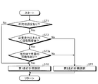
- FIG. 3 is a flowchart for selecting a travel plan of the ECU of the travel control apparatus according to the embodiment.
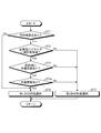
- FIG. 4 is a flowchart illustrating a second travel plan of the ECU of the travel control apparatus according to the embodiment.
- FIG. 5 is a flowchart showing a first travel plan of the ECU of the travel control apparatus according to the embodiment.
- FIG. 6 is a diagram for explaining the change in the SOC with respect to the travel distance of the comparative example and the present invention.
- FIG. 1 is a schematic configuration diagram of a hybrid vehicle including a travel control device according to an embodiment.
- FIG. 2 is a schematic configuration diagram of an ECU and a navigation device of the travel control device according to the embodiment.
- FIG. 3 is a flowchart for selecting a
- FIG. 7 is a flowchart for selecting a travel plan of the ECU of the travel control apparatus according to the modification according to the embodiment.
- FIG. 8 is an explanatory diagram illustrating a map for setting the ratio of the first travel plan of the drive switching unit of the ECU of the travel control apparatus according to the modification according to the embodiment.
- FIG. 9 is a flowchart for selecting a travel plan of the ECU of the travel control apparatus according to the first disclosure.
- FIG. 10 is a flowchart for selecting a travel plan of the ECU of the travel control apparatus according to the second disclosed example.
- FIG. 11 is a flowchart for selecting a travel plan of the ECU of the travel control apparatus according to the third disclosure.
- FIG. 1 is a schematic configuration diagram of a hybrid vehicle including a travel control device according to the embodiment
- FIG. 2 is a schematic configuration diagram of an ECU and a navigation device of the travel control device according to the embodiment.
- the travel control device 1 according to the present embodiment is a so-called hybrid vehicle 2 that combines an engine 5 and an MG 6 as a motor to serve as a travel drive source for rotationally driving drive wheels. Installed.
- the travel control device 1 includes an ECU (Electronic Control Unit) 50.
- the travel control device 1 selects the travel plan of the hybrid vehicle 2 by the ECU 50 controlling the engine 5, the MG 6 and a transmission 7 described later according to the situation.
- the travel control device 1 of the present embodiment selects a travel plan based on the expected charging time during which the battery 9 at the destination can be charged. Thereby, the traveling control device 1 is configured to allow further reduction in running cost of the hybrid vehicle 2 as a whole.
- the travel control device 1 of the present embodiment includes a first travel plan that prohibits an HV mode in a high load state among an EV mode and an HV mode, which will be described later, and a second travel plan that allows an HV mode in a high load state. And select.
- the hybrid vehicle 2 includes an engine 5 as an internal combustion engine, a motor generator (hereinafter referred to as “MG”) 6, a transmission 7, a brake device 8, a battery 9, and the like.
- the hybrid vehicle 2 includes a vehicle speed sensor 10, an accelerator sensor 11, a brake sensor 12, a navigation device 13, and the like.
- the engine 5 causes the driving force to act on the wheels of the hybrid vehicle 2 in response to an acceleration request operation by the driver, for example, an accelerator pedal depression operation.
- the engine 5 consumes fuel and generates an engine torque as an engine torque as a driving force to be applied to the driving wheels of the hybrid vehicle 2.
- the engine 5 is a heat engine that outputs thermal energy generated by burning fuel in the form of mechanical energy such as torque, and examples thereof include a gasoline engine, a diesel engine, and an LPG engine.
- the engine 5 includes, for example, a fuel injection device, an ignition device, a throttle valve device, and the like (not shown). These devices are electrically connected to the ECU 50 and controlled by the ECU 50.
- the output torque of the engine 5 is controlled by the ECU 50.
- the driving force generated by the engine 5 may be used for power generation in the MG 6.
- MG6 causes the driving force to act on the wheels of the hybrid vehicle 2 in response to an acceleration request operation by the driver, for example, an accelerator pedal depression operation.
- the MG 6 converts electric energy into mechanical power and generates motor torque as travel driving force that acts on the drive wheels of the hybrid vehicle 2.
- MG6 is what is called a rotary electric machine provided with the stator which is a stator, and the rotor which is a rotor.
- the MG 6 is an electric motor that converts electric energy into mechanical power and outputs it, and also a generator that converts mechanical power into electric energy and recovers it.
- the MG 6 is driven by supplying electric power, functions as an electric motor that converts electric energy into mechanical energy and outputs it (power running function), and functions as a generator that converts mechanical energy into electric energy (regenerative function).
- the MG 6 is electrically connected to the ECU 50 through an inverter or the like that converts direct current and alternating current, and is controlled by the ECU 50.
- the output torque and power generation amount of the MG 6 are controlled by the ECU 50 via an inverter.
- the transmission 7 is a power transmission device that shifts the rotational driving force of the engine 5 and the MG 6 and transmits it to the driving wheel side of the hybrid vehicle 2.
- the transmission 7 may be a so-called manual transmission (MT), a stepped automatic transmission (AT), a continuously variable automatic transmission (CVT), a multimode manual transmission (MMT), a sequential manual transmission (SMT). ), A so-called automatic transmission such as a dual clutch transmission (DCT).
- MT manual transmission
- AT continuously variable automatic transmission
- MMT multimode manual transmission
- SMT sequential manual transmission
- DCT dual clutch transmission
- the transmission 7 is controlled by the ECU 50 with a transmission actuator or the like electrically connected to the ECU 50.
- the brake device 8 applies a braking force to the wheels of the hybrid vehicle 2 in response to a braking request operation by the driver, for example, a depression operation of a brake pedal.
- the brake device 8 applies a braking force to a wheel rotatably supported by the vehicle body of the hybrid vehicle 2 by generating a predetermined friction force (friction resistance force) between friction elements such as a brake pad and a brake disk, for example. To do.
- the brake device 8 can generate a braking force on the ground contact surface with the road surface of the wheel of the hybrid vehicle 2 to brake the hybrid vehicle 2.
- the brake device 8 is controlled by the ECU 50 with a brake actuator or the like electrically connected to the ECU 50.
- the battery 9 is a power storage device capable of storing electric power (electric storage) and discharging the stored electric power.
- the battery 9 is electrically connected to the ECU 50 and outputs signals related to various information to the ECU 50.
- the battery 9 according to the present embodiment detects a state of charge (hereinafter referred to as SOC) and outputs the detected result to the ECU 50.
- the battery 9 is connected to the MG 6 via an inverter (not shown). Further, the battery 9 is connected to a connector 15 connected to an external power source 14 such as a household power source via an inverter. The battery 9 is supplied with power from an external power source 14 such as a household power source via a connector 15 and an inverter. For this reason, the battery 9 can be charged with electric power from the external power supply 14 by connecting the external power supply 14 to the connector 15.
- the external power supply 14 as used in the field of this invention means the power supply which can charge the battery 9 via the connector 15 grade
- the MG 6 When the MG 6 functions as an electric motor, the electric power stored in the battery 9 is supplied via an inverter, and the supplied electric power is converted into a driving force for driving the hybrid vehicle 2 and output. Moreover, when MG6 functions as a generator, it generates electric power with the input driving force and charges the battery 9 with the generated electric power via an inverter. At this time, the MG 6 can brake the rotation of the rotor (regenerative braking) by the rotational resistance generated in the rotor. As a result, during regenerative braking, the MG 6 can generate a motor regenerative torque, which is a negative motor torque, in the rotor by regenerating electric power.
- a motor regenerative torque which is a negative motor torque
- the MG 6 can apply a braking force to the drive wheels of the hybrid vehicle 2. It can. That is, in the hybrid vehicle 2, mechanical power is input from the drive wheels to the MG 6, and the MG 6 generates electric power by regeneration, whereby the kinetic energy of the hybrid vehicle 2 can be recovered as electric energy. And the hybrid vehicle 2 can perform regenerative braking by MG6 by transmitting the mechanical power (negative motor torque) which arises in the rotor of MG6 in connection with this to a driving wheel. In this case, in the hybrid vehicle 2, when the regeneration amount (power generation amount) by the MG 6 is relatively small, the generated braking force is relatively small, and the deceleration acting on the hybrid vehicle 2 is relatively small. Become. On the other hand, in the hybrid vehicle 2, when the regeneration amount (power generation amount) by the MG 6 is relatively increased, the generated braking force is relatively increased, and the deceleration acting on the hybrid vehicle 2 is relatively increased. .
- the vehicle speed sensor 10, the accelerator sensor 11, and the brake sensor 12 are input to the hybrid vehicle 2 by the driving state of the hybrid vehicle 2 (driver input), that is, state quantities and physical quantities related to the actual operation of the hybrid vehicle 2 by the driver.
- driver input that is, state quantities and physical quantities related to the actual operation of the hybrid vehicle 2 by the driver.
- vehicle speed detects the vehicle speed of the hybrid vehicle 2 (hereinafter sometimes referred to as “vehicle speed”).
- the accelerator sensor 11 detects an accelerator opening that is an operation amount (depression amount) of an accelerator pedal by a driver.
- the brake sensor 12 detects an operation amount (depression amount) of the brake pedal by the driver, for example, a master cylinder pressure.
- the vehicle speed sensor 10, the accelerator sensor 11 and the brake sensor 12 are electrically connected to the ECU 50 and output detection signals to the ECU 50.
- the navigation device 13 detects the current position and obtains the position of the hybrid vehicle 2 in the map information stored in advance, calculates the travel route to the destination, and travels to the position of the hybrid vehicle 2 and the destination. It is a device that displays routes and the like.
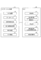
- the navigation device 13 is an in-vehicle device mounted in the hybrid vehicle 2, and as shown in FIG. 2, a GPS (Global Positioning System, Global Positioning System) device (hereinafter referred to as “GPS”) 16 and a database 17. , Destination setting unit 18, travel route setting unit 19, display device 20, input device 21 and the like.
- GPS Global Positioning System, Global Positioning System
- the GPS device 16 is a device that detects the current position of the hybrid vehicle 2.
- the GPS device 16 receives a GPS signal output from a GPS satellite, and measures and calculates GPS information (X coordinate; X, Y coordinate; Y) that is position information of the hybrid vehicle 2 based on the received GPS signal. .
- the GPS device 16 is electrically connected to the ECU 50 and outputs a signal related to GPS information to the ECU 50.
- the database 17 stores various information.
- the database 17 stores map information including road information, various information obtained by actual traveling of the hybrid vehicle 2, learning information, and the like.
- the road information includes road gradient information, road surface state information, road shape information, restricted vehicle speed information, road curvature (curve) information, temporary stop information, stop line position information, and the like.
- Information stored in the database 17 is appropriately referred to by the ECU 50, and necessary information is read out.
- the database 17 is illustrated here as being mounted on the hybrid vehicle 2, but is not limited thereto, and is provided in an information center or the like outside the hybrid vehicle 2 via wireless communication or the like (not shown). A configuration may be employed in which necessary information is read by appropriately referring to the ECU 50.
- the database 17 of the present embodiment stores information indicating whether or not the external power source 14 capable of charging the battery 9 exists at the destination set in the destination setting unit 18 as map information. .
- the destination setting unit 18 receives information indicating the position of the destination of the hybrid vehicle 2 from an occupant or the like via the input device 21.
- the destination setting unit 18 reads information indicating the position of the destination by appropriately referring to the ECU 50.
- the information indicating the position of the destination input to the destination setting unit 18 is, for example, the information from the GPS device 16 when a predetermined time has elapsed since the input of the information indicating the position of the destination from the input device 21. Based on this, it is deleted when the destination input from the input device 21 is reached.
- the travel route setting unit 19 uses GPS information (X coordinate; X, Y coordinate; Y), which is current position information of the hybrid vehicle 2 measured and calculated by the GPS device 16, and map information stored in the database 17. Based on this, the travel route to the destination is calculated and stored. In the travel route setting unit 19, information indicating the travel route to the destination is appropriately referred to by the ECU 50 and read out.
- the display device 20 includes a display device (visual information display device), a speaker (sound output device), and the like provided in the passenger compartment of the hybrid vehicle 2.
- the display device 20 displays the position, destination, and travel route of the hybrid vehicle 2 with map information and the like.
- the input device 21 has operation buttons and the like provided in the passenger compartment of the hybrid vehicle 2. The input device 21 is used for inputting a destination and the like.
- the ECU 50 is a control unit that performs overall control of the hybrid vehicle 2 and is configured as an electronic circuit mainly including a known microcomputer including a CPU, a ROM, a RAM, and an interface, for example.
- the ECU 50 corresponds to detection results detected by the vehicle speed sensor 10, the accelerator sensor 11, and the brake sensor 12, GPS information acquired by the GPS device 16, various information stored in the database 17, drive signals of each unit, control commands, and the like.
- the electrical signal is input.
- the ECU 50 controls the engine 5, the MG 6, the transmission 7, the brake device 8, the battery 9, and the like according to these input electric signals.
- the ECU 50 executes drive control of the engine 5, drive control of the MG 6, shift control of the transmission 7, brake control of the brake device 8, and the like based on the accelerator opening, the vehicle speed, and the like.
- ECU50 implement
- the EV mode refers to a travel mode in which the hybrid vehicle 2 travels only by the travel driving force of the MG 6, and the HV mode refers to a travel mode in which the hybrid vehicle 2 travels by at least the travel drive force of the engine 5.
- the ECU 50 operates the engine 5 in the most efficient state as much as possible, while making the MG 6 that is the rotating electrical machine compensate for excess or deficiency of the driving force or engine braking force, and further reduce the energy during deceleration. By improving the fuel efficiency, the fuel efficiency will be improved.
- the ECU 50 can detect ON / OFF of an accelerator operation, which is an acceleration request operation for the hybrid vehicle 2 by the driver, and an accelerator opening based on a detection result by the accelerator sensor 11.
- the ECU 50 can detect ON / OFF of a brake operation, which is a brake request operation for the hybrid vehicle 2 by the driver, based on a detection result by the brake sensor 12, for example.
- the state where the accelerator operation by the driver is OFF is a state where the driver cancels the acceleration request operation for the hybrid vehicle 2
- the state where the accelerator operation by the driver is ON is the state where the driver is the hybrid vehicle. This is a state in which an acceleration requesting operation for 2 is being performed.
- the state where the brake operation by the driver is OFF is a state where the driver releases the braking request operation for the hybrid vehicle 2
- the state where the brake operation by the driver is ON is the state where the driver is hybrid. This is a state in which a braking request operation for the vehicle 2 is being performed.
- the ECU 50 detects the driver request power based on the accelerator opening.
- the travel control device 1 is configured by the ECU 50 described above.
- the travel control device 1 may include the navigation device 13, various sensors that detect the vehicle state, and various information acquisition units that supply surrounding information, in addition to the ECU 50.
- the ECU 50 selects the first travel plan and the second travel plan according to the situation, and selects the EV mode and the HV mode in each travel plan. Can be further reduced.
- the ECU 50 when the destination is set in the destination setting unit 18, the ECU 50 is required when traveling to the destination only in the EV mode based on the travel route calculated by the travel route setting unit 19. It is determined whether or not the electric power (corresponding to the required travel energy) is less than the current remaining capacity of the battery 9.
- the traveling control device 1 When it is determined that the traveling control device 1 is below, the external power supply 14 exists at the destination with reference to the information in the database 17 and the expected charging time at the destination is determined based on the information in the storage unit 51 described later.
- the first travel plan is selected.
- the traveling control apparatus 1 is either in the case where the required traveling energy does not fall below the current remaining capacity, the case where the external power source 14 does not exist at the destination, or the case where the estimated expected charging time is short. If there is, the second travel plan is selected.
- the ECU 50 includes a storage unit 51, a first estimation unit (corresponding to a required travel energy estimation unit) 52, a determination unit 53, and a second estimation unit (corresponding to a charging time estimation unit). ) 54 and a drive switching unit 55.
- the storage unit 51 refers to the information of the navigation device 13 and calculates the time required for the battery 9 to be actually charged from the external power source 14 (hereinafter referred to as the actual charging time) for each position where the hybrid vehicle 2 is stopped. Classify and memorize.
- the storage unit 51 appropriately accumulates and stores the actual charging time for each position where the hybrid vehicle 2 stops. Specifically, the storage unit 51 has past actual actual charging times A1, A2... An at the stopped position A where the X coordinate is x1 and the Y coordinate is y1, and the X coordinate is x2, Y. If the past actual charging time at the stopped position B where the coordinate is y2 is B1, B2,... Bn, the stopped position A and the actual charging times A1, A2,. The stored position B and the actual charging times B1, B2,... Bn are stored in association with each other.
- the first estimation unit 52 Based on the travel route calculated by the travel route setting unit 19, the first estimation unit 52 requires electric power (corresponding to the required travel energy) when traveling in the EV mode only to the destination input from the input device 21. Estimate).
- the determination unit 53 refers to the information of the destination setting unit 18 of the navigation device 13 and determines whether or not the destination is set in the destination setting unit 18. Further, the determination unit 53 determines whether or not the electric power corresponding to the required travel energy estimated by the first estimation unit 52 is less than the current remaining capacity of the battery 9. Further, the determination unit 53 refers to the information of the destination setting unit 18 of the navigation device 13 and the database 17 to determine whether or not the external power supply 14 exists at the destination.
- the second estimating unit 54 predicts the expected charging time (battery 9 from the external power supply 14) at the destination input from the input device 21.
- the time during which the hybrid vehicle 2 can be charged and the hybrid vehicle 2 is stopped is estimated.
- an average value of past actual charging time at the destination input from the input device 21 is calculated from the information stored in the storage unit 51, and the calculated average value is set as the expected charging time.
- the second estimation unit 54 calculates an average value of past charging times A1, A2,... An stored in the storage unit 51. The calculated average value is set as the expected charging time.
- the second estimation unit 54 determines a value other than the average value as long as it is a value obtained from the past actual charging times A1, A2,... An stored in the storage unit 51. It is also good.
- the default value input in advance is set as the expected charging time. It is desirable that this default value exceeds a threshold that will be described later.
- the drive switching unit 55 selects the first travel plan when the expected charging time estimated by the second estimation unit 54 exceeds a predetermined threshold. Moreover, the drive switching part 55 selects a 2nd driving
- FIGS. 3 is a flowchart for selecting a travel plan of the ECU of the travel control apparatus according to the embodiment
- FIG. 4 is a flowchart of a second travel plan of the ECU of the travel control apparatus according to the embodiment.
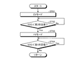
- the determination unit 53 of the ECU 50 of the travel control device 1 refers to the information from the navigation device 13 in step ST1 of FIG. It is determined whether or not the indicated information is input. That is, the determination unit 53 of the ECU 50 of the travel control device 1 determines whether or not the destination is set. If it is determined that the destination is set, the process proceeds to step ST2 and the destination is not set. If it determines, it will progress to step ST6.
- the hybrid vehicle 2 activated in the present invention refers to a state in which the hybrid vehicle 2 can immediately travel by turning on the power of the hybrid vehicle 2 and operating the accelerator pedal.
- step ST2 the first estimation unit 52 of the ECU 50 of the travel control device 1 estimates power corresponding to the required travel energy based on the travel route calculated by the travel route setting unit 19.
- step ST ⁇ b> 2 the determination unit 53 of the ECU 50 of the travel control device 1 determines whether the electric power corresponding to the estimated required travel energy is below the current remaining capacity of the battery 9.
- the process proceeds to step ST3, and when it is determined that the power is not below, Proceed to step ST7.
- step ST ⁇ b> 3 the determination unit 53 of the ECU 50 of the travel control device 1 refers to the information of the navigation device 13 and determines whether or not the external power source 14 exists at the destination set in the destination setting unit 18. . If the determination unit 53 of the ECU 50 of the travel control device 1 determines that the external power supply 14 is present, the process proceeds to step ST4. If the determination unit 53 determines that the external power supply 14 is not present, the process proceeds to step ST7.
- step ST4 the second estimation unit 54 of the ECU 50 of the travel control device 1 estimates the expected charging time at the destination based on the information stored in the storage unit 51, and proceeds to step ST5.
- step ST5 the drive switching unit 55 of the ECU 50 of the travel control device 1 determines whether or not the expected charging time estimated by the second estimation unit 54 exceeds a threshold value. If the drive switching unit 55 of the ECU 50 of the travel control device 1 determines that the threshold is exceeded, the process proceeds to step ST6, selects the first travel plan, and if it is determined that the threshold is not exceeded, the step Proceeding to ST7, the second travel plan is selected.
- step ST7 the drive switching unit 55 of the ECU 50 of the travel control device 1 selects the EV mode and stops or stops the engine 5 in step ST71 in FIG. Maintain and drive only MG6. Then, the drive switching unit 55 of the ECU 50 of the travel control device 1 causes the hybrid vehicle 2 to travel using only the travel driving force of the MG 6 and proceeds to step ST72. In step ST72, the drive switching unit 55 of the ECU 50 of the travel control device 1 determines whether or not the SOC of the battery 9 is below a predetermined first predetermined value.
- step ST74 the SOC of the battery 9 falls below a predetermined first predetermined value. If it is determined that there is not, the process proceeds to step ST73.
- step ST73 the drive switching unit 55 of the ECU 50 of the travel control device 1 requires a relatively large drive torque such as high-speed travel or uphill travel based on information from the transmission 7, the accelerator sensor 11, and the vehicle speed sensor 10. It is determined whether the load is high. If the drive switching unit 55 of the travel control device 1 determines that the hybrid vehicle 2 is in a high load state, the process proceeds to step ST74. If the hybrid vehicle 2 determines that the hybrid vehicle 2 is not in a high load state, the drive switching unit 55 returns to step ST72. Thus, the drive switching unit 55 of the travel control device 1 performs steps ST72 and ST73 until the SOC falls below a predetermined first predetermined value or the hybrid vehicle 2 corresponds to either a high load state. Repeatedly, the EV mode is maintained and the hybrid vehicle 2 is driven only by the driving force of the MG 6.
- step ST74 the drive switching unit 55 of the ECU 50 of the travel control device 1 selects the HV mode and drives the engine 5. Then, the drive switching unit 55 of the ECU 50 of the travel control device 1 causes the hybrid vehicle 2 to travel with at least the travel driving force of the engine 5, and the process proceeds to step ST75.
- the drive switching unit 55 of the ECU 50 of the travel control device 1 corresponds to either the state where the SOC is lower than the predetermined first predetermined value or the hybrid vehicle 2 is in the high load state. Then, it progresses to step ST74, HV mode is selected, and the hybrid vehicle 2 is drive
- step ST74 the drive switching unit 55 of the ECU 50 of the travel control device 1 operates the engine 5 in the most efficient state possible, while the transmission 7, the accelerator sensor 11, the brake sensor 12, and the vehicle speed sensor 10 are operated. Based on the information from MG6, the MG6 compensates for excess or deficiency of the driving force or engine braking force.
- the drive switching unit 55 of the ECU 50 of the travel control device 1 causes the MG 6 to perform regenerative braking to apply braking force to the driving wheels of the hybrid vehicle 2 during deceleration, and the battery 9 is connected to the power generated by the MG 6. Let it charge.
- the drive switching unit 55 of the ECU 50 of the travel control device 1 causes the MG 6 to perform regenerative braking during deceleration to charge the battery 9 and restore the SOC.
- step ST75 the drive switching unit 55 of the ECU 50 of the travel control device 1 determines whether or not the SOC of the battery 9 is below a predetermined first predetermined value. If the drive switching unit 55 of the ECU 50 of the travel control device 1 determines that the SOC of the battery 9 is less than the first predetermined value, it repeats step ST75 and determines that the SOC of the battery 9 does not fall below the first predetermined value. Proceed to ST76.
- step ST76 the drive switching unit 55 of the ECU 50 of the travel control device 1 determines whether or not the vehicle is in a high load state based on information from the transmission 7, the accelerator sensor 11, and the vehicle speed sensor 10. If the drive switching unit 55 of the ECU 50 of the travel control device 1 determines that the hybrid vehicle 2 is in a high load state, the drive switching unit 55 returns to step ST75. If the hybrid vehicle 2 determines that the hybrid vehicle 2 is not in a high load state, the drive switching unit 55 returns to step ST71. Thus, when the HV mode is selected, the drive switching unit 55 of the ECU 50 of the travel control device 1 performs steps ST75 and ST76 until the SOC does not fall below the first predetermined value and the hybrid vehicle 2 is not in a high load state.
- the drive switching unit 55 of the travel control device 1 returns to step ST71 when the SOC does not fall below a first predetermined value and the hybrid vehicle 2 is not in a high load state. Select EV mode.
- step ST6 the drive switching unit 55 of the ECU 50 of the travel control device 1 selects the EV mode and stops the engine 5 in step ST61 in FIG. Maintain and drive only MG6. Then, the drive switching unit 55 of the ECU 50 of the travel control device 1 causes the hybrid vehicle 2 to travel using only the travel driving force of the MG 6 and proceeds to step ST62. In step ST62, the drive switching unit 55 of the ECU 50 of the travel control device 1 determines whether or not the SOC of the battery 9 is below a predetermined second predetermined value.
- the second predetermined value is a value that is different from the first predetermined value described above and is sufficiently smaller than the first predetermined value.
- step ST63 the SOC of the battery 9 is determined to be a predetermined second predetermined value. If it is determined that the value does not fall below, step ST62 is repeated.
- step ST63 the drive switching unit 55 of the ECU 50 of the travel control device 1 selects the HV mode and drives the engine 5. Then, the drive switching unit 55 of the ECU 50 of the travel control device 1 causes the hybrid vehicle 2 to travel with at least the travel driving force of the engine 5 and proceeds to step ST64. Also in this step ST64, the drive switching unit 55 of the ECU 50 of the travel control device 1 operates the engine 5 in the most efficient state as in the above-described step ST74, while the travel drive force and the engine brake force.
- the MG 6 is compensated for excess and deficiency, and the battery 9 is charged with the electric power generated by the MG 6.
- step ST64 the drive switching unit 55 of the ECU 50 of the travel control device 1 determines whether or not the SOC of the battery 9 is below the first predetermined value described above.
- the step ST64 is repeated, and when it is determined that the SOC of the battery 9 is not lower than the first predetermined value, the step Returning to ST61, the EV mode is selected.
- the drive switching unit 55 of the ECU 50 of the travel control device 1 repeats step ST62 until the SOC falls below the second predetermined value that is sufficiently smaller than the first predetermined value, and maintains the EV mode.
- the hybrid vehicle 2 is driven only by the driving force of the MG 6. That is, the drive switching unit 55 of the ECU 50 of the travel control device 1 causes the hybrid vehicle 2 to travel only by the travel driving force of the MG 6 until the SOC falls below the second predetermined value that is sufficiently smaller than the first predetermined value.
- the EV mode and the HV mode are selected so as to increase the frequency of the EV mode by prohibiting the frequency of the HV mode at the time of high load until the destination is reached.
- the drive switching unit 55 of the travel control device 1 sets the first travel plan when the estimated charging time estimated by the second estimating unit 54 is long as the second traveling plan when the estimated expected charging time is short.
- the EV mode and the HV mode are selected so that the frequency of the EV mode increases and the frequency of the HV mode at high load is suppressed until the destination is reached, rather than the travel plan.
- the first travel plan corresponds to a case where the expected charging time estimated by the second estimation unit 54 is long, and the second travel plan is the expected charging time estimated by the second estimation unit 54. Corresponds to the case where is short.
- the electric power charged in the battery 9 can be reliably used for the travel of the hybrid vehicle 2, and the deterioration of the fuel consumption due to the driving of the engine 5 is suppressed, and the running cost of the hybrid vehicle 2 as a whole is further reduced. Can be possible.
- the HV mode at the time of high load is allowed, so that the battery 9 can be charged before reaching the destination. Therefore, it is possible to suppress charging of the battery 9 during traveling after the departure from the destination, to suppress deterioration of fuel consumption, and to further reduce the running cost of the hybrid vehicle 2 as a whole.
- the second estimation unit 54 estimates the expected charging time at the destination based on the actual charging time for each stop position of the hybrid vehicle 2 stored in the storage unit 51, the expected charging time, that is, the battery at the destination. 9 can be estimated accurately.
- the second predetermined value is set to a value smaller than the first predetermined value, in the first travel plan, the electric power charged in the battery 9 can be reliably used for the travel of the hybrid vehicle 2. Further, the deterioration of fuel consumption due to the driving of the engine 5 can be reliably suppressed, and the running cost of the hybrid vehicle 2 as a whole can be reliably reduced.
- the drive switching unit 55 determines the first travel plan. select. For this reason, when the second estimation unit 54 uses the above-described default value as the expected charging time, or when the destination is not set in the destination setting unit 18, the SOC falls below the second predetermined value. Since the engine 5 is not driven even in a high load state, the running cost of the hybrid vehicle 2 as a whole can be reliably reduced. Further, even when the second estimation unit 54 sets the above-described default value as the expected charging time or when the destination is not set in the destination setting unit 18, if the SOC falls below the second predetermined value, the HV mode is set. Since the hybrid vehicle 2 is driven with the driving force of the engine 5 selected, the SOC of the battery 9 can be recovered.
- the travel control device 1 of the present embodiment drives the engine 5 even in a high load state until the SOC falls below the second predetermined value, as shown in FIG. Therefore, the running cost of the hybrid vehicle 2 as a whole can be reliably reduced.
- the horizontal axis in FIG. 6 indicates the travel distance of the hybrid vehicle 2
- the vertical axis indicates the SOC of the battery 9.
- Comparative Example 1 selects only the second travel plan, selects the HV mode in a high load state between ab, selects the HV mode for the SOC to fall below the first predetermined value between dB, and the remaining In the comparative example 2, only the second travel plan is selected, the EV mode is selected between 0A, and the SOC is lower than the first predetermined value between AB.
- the conventional example which selects is shown. Comparative Example 1 is indicated by a one-dot chain line in FIG. 6, and Comparative Example 2 is indicated by a dotted line in FIG.
- the present invention 1 shows the above-described embodiment in which the first travel plan, that is, the EV mode is selected in all sections by fully charging the battery at A, and the present invention 2 does not charge the battery at A. Furthermore, the above-described embodiment is shown in which the first travel plan, that is, the EV mode is selected between 0c, and the HV mode is selected because the SOC is lower than the second predetermined value between cB.
- the present invention 1 is indicated by a solid line in FIG. 6, and the present invention 2 is indicated by a two-dot chain line in FIG.
- FIG. 6 is a figure explaining the change of SOC with respect to the travel distance of a comparative example and this invention.
- FIG. 7 is a flowchart for selecting a travel plan of the ECU of the travel control apparatus according to the modification according to the embodiment
- FIG. 8 is a flowchart of the drive switching unit of the ECU of the travel control apparatus according to the modification according to the embodiment. It is explanatory drawing which shows the map for setting the ratio of 1 travel plan.
- the same part as embodiment mentioned above is attached
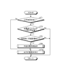
- the drive switching unit 55 of the ECU 50 of the travel control device 1 performs the first travel plan and the second travel plan based on the expected charging time estimated by the second estimation unit 54 in step ST5a shown in FIG. And set the ratio.
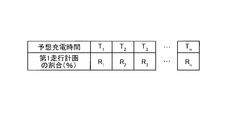
- the drive switching unit 55 stores in advance a map showing the relationship between the estimated expected charging time and the first travel plan shown in FIG. The ratio of the first travel plan corresponding to the estimated charging time is read from the map shown in FIG.
- the expected charging time T 1, and T 2, T 3 ⁇ T n corresponds one-to-one and has, has at the expected charging time T 1> T 2> T 3 > ⁇ > T n, and the ratio R 1> R 2> R 3 > ⁇ > R n.
- the ratio R 1 of the time expected charging time T 1 is 100%, the ratio R n when the expected charging time T n is 0%.
- the drive switching unit 55 reads a ratio corresponding to the expected charging time estimated by the second estimation unit 54 from the map shown in FIG.
- the expected charging time estimated by the second estimating unit 54 does not correspond to any of the expected charging times T 1 , T 2 , T 3 ... T n of the map shown in FIG.
- the ratios R 1 , R 2 , R 3 ... R n corresponding to the expected charging times T 1 , T 2 , T 3 ... T n closest to the expected charging time estimated by the second estimating unit 54 are read. .
- the drive switching unit 55, the expected charging time second estimation unit 54 has estimated longer than expected charging time T 1 the ratio of the first travel plan as a R 1, expected charging second estimation unit 54 has estimated When shorter than the expected charging time T n time, the ratio of the first travel plan and R n.
- the drive switching unit 55 divides the distance to the destination into the distance traveled by the first travel plan and the distance traveled by the second travel plan according to the ratio obtained from the map shown in FIG.
- the hybrid vehicle 2 is caused to travel by switching between the first travel plan and the second travel plan to the destination according to the divided distance.
- the prediction estimated by the second estimation unit 54 is gradually increased by increasing the ratio of traveling in the first travel plan.
- the EV mode and the HV mode are selected so that the frequency of the EV mode increases until the destination is reached, compared to when the expected charging time is short.
- the prediction estimated by the second estimation unit 54 is gradually increased by increasing the ratio of traveling in the first travel plan.
- the EV mode and the HV mode are selected so as to suppress the frequency of the HV mode at the time of high load until the destination is reached, compared to the case where the expected charging time is short.
- the travel control device 1 of the present modified example suppresses the deterioration of fuel consumption due to the drive of the engine 5 and can further reduce the running cost of the hybrid vehicle 2 as a whole. can do.
- FIG. 9 is a flowchart for changing a travel plan of the ECU of the travel control apparatus according to the first disclosure.
- the same parts as those in the embodiment and the modification described above are denoted by the same reference numerals and the description thereof is omitted.
- step ST3a when it is determined that the electric power corresponding to the required travel energy estimated by the determination unit 53 in step ST2 illustrated in FIG. 9 is lower than the current remaining capacity of the battery 9, the travel control device 1 in step ST3a.
- the determination unit 53 of the ECU 50 may be charged from the external power source 14 at the destination set in the destination setting unit 18 with reference to the information of the navigation device 13 and the information stored in the storage unit 51. It is determined whether or not.
- step ST3a it is determined that there is a possibility of charging when the external power source 14 is present at the destination and the battery 9 has been charged by the external power source 14 in the past at the position set as the destination. To do.
- step ST3a when the determination unit 53 of the ECU 50 of the travel control device 1 determines that there is a possibility of charging from the external power source 14 at the destination set in the destination setting unit 18, the process proceeds to step ST6, where there is a possibility. If it is determined that there is not, the process proceeds to step ST7.
- the determination unit 53 of the ECU 50 of the travel control device 1 determines that there is a possibility of charging from the external power source 14 at the destination set in the destination setting unit 18, the first travel plan is executed. Therefore, the deterioration of fuel consumption due to driving of the engine 5 can be suppressed, and the running cost of the hybrid vehicle 2 as a whole can be further reduced.
- FIG. 10 is a flowchart for changing the travel plan of the ECU of the travel control apparatus according to the second disclosed example. Note that, in the disclosure example 2, the same parts as those in the above-described embodiment and modification are denoted by the same reference numerals and description thereof is omitted.
- step ST6 when the determination unit 53 of the ECU 50 of the travel control device 1 determines that the external power source 14 exists at the destination set in the destination setting unit 18 in step ST3 illustrated in FIG. 10, the process proceeds to step ST6. If it is determined that the external power supply 14 does not exist, the process proceeds to step ST7.
- the first travel plan is selected.
- the deterioration of fuel consumption due to driving can be suppressed, and the running cost of the hybrid vehicle 2 as a whole can be further reduced.
- FIG. 11 is a flowchart for changing the travel plan of the ECU of the travel control apparatus according to the third disclosure. Note that, in the disclosure example 3, the same parts as those in the embodiment and the modification described above are denoted by the same reference numerals and the description thereof is omitted.
- step ST4a shown in FIG. 11 the determination unit 53 of the ECU 50 of the travel control device 1 refers to the information in the storage unit 51 in the destination set in the destination setting unit 18 in the past. Then, it is determined whether or not the battery 9 is charged by the external power source 14. If it is determined that the battery 9 is charged, the process proceeds to step ST6. If it is determined that the battery 9 is not charged, the process proceeds to step ST7.
- the determination unit 53 of the ECU 50 of the travel control device 1 determines that the battery 9 is charged at the destination set in the destination setting unit 18, the first travel plan is selected.
- the deterioration of fuel consumption due to driving can be suppressed, and the running cost of the hybrid vehicle 2 as a whole can be further reduced.
- the travel control device 1 according to the above-described embodiment of the present invention is not limited to the above-described embodiment and modifications, and various modifications can be made without changing the gist of the present invention.
- the travel control apparatus according to the present embodiment may be configured by appropriately combining the constituent elements of the embodiment and the modification described above.
- the first predetermined value and the second predetermined value are different from each other, and the second predetermined value is smaller than the first predetermined value.
- the first predetermined value and the second predetermined value may be made equal.
- the HV mode is not selected even in a high load state, so that deterioration of fuel consumption due to driving of the engine 5 is suppressed, and the running cost of the hybrid vehicle 2 as a whole is further reduced. Can be made possible.
- MG6 which has a power running function and a regeneration function was used as a motor
- this invention is not limited to this,
- a motor provided with a power running function and a regeneration function are provided.
- a generator e.g., a motor provided with a power running function and a regeneration function.
Abstract
An objective of the present invention is to provide a travel control device with which it is possible to further reduce running costs of a hybrid vehicle overall. A travel control device (1) selects a travel mode of a hybrid vehicle comprising a battery which can be charged by power from an external power source, a motor generator (MG) which generates travel drive power from the battery power, and an engine which generates travel drive power. The travel control device (1) comprises a second estimation unit (54), and a drive switch unit (55). The second estimation unit (54) estimates a forecast charging time in which charging the battery is possible in the destination. When the forecast charging time which is estimated by the second estimation unit (54) is long, the drive switch unit (55) increases the EV mode frequency until the destination is reached in comparison with when the forecast charging time is short.
Description
本発明は、走行制御装置に関する。
The present invention relates to a travel control device.
従来、車両に搭載され、車両の走行を制御する走行制御装置が知られている。例えば、特許文献1には、車輌の駆動源としてモータとエンジンとを備えたハイブリッド車において、運転条件によって、モータの走行駆動力のみにより走行するか、少なくともエンジンの走行駆動力により走行するか、を選択するハイブリッド車の走行制御装置が記載されている。
Conventionally, a travel control device that is mounted on a vehicle and controls the travel of the vehicle is known. For example, in Patent Document 1, in a hybrid vehicle including a motor and an engine as a vehicle drive source, depending on driving conditions, the vehicle travels only by the driving force of the motor, or at least by the driving force of the engine, A travel control device for a hybrid vehicle that selects is described.
前述した特許文献1などに示された従来から用いられてきたハイブリッド車の走行制御装置は、モータに電力を供給するバッテリ(所謂、二次電池をいう)の充電状態(state-of-charge:以下、SOCと呼ぶ)が予め定められた第1所定値を下回る状態と、高速走行や登坂走行などの比較的大きな駆動トルクが必要な高負荷状態と、のうちのいずれかに該当するか否かを判定する。前記走行制御装置は、SOCが予め定められた第1所定値を下回る状態と、高速走行や登坂走行などの比較的大きな駆動トルクが必要な高負荷状態と、のうちのいずれかに該当すると判定すると、少なくともエンジンの走行駆動力により走行することを選択する。また、前記走行制御装置は、SOCが予め定められた第1所定値を下回る状態と、高速走行や登坂走行などの比較的大きな駆動トルクが必要な高負荷状態と、のうちのいずれかにも該当しないと判定すると、モータの走行駆動力のみにより走行することを選択する。
Conventionally, a hybrid vehicle travel control apparatus disclosed in Patent Document 1 described above and the like has a state-of-charge of a battery (referred to as a secondary battery) that supplies electric power to a motor. (Hereinafter referred to as “SOC”) falls under one of a predetermined first predetermined value and a high load state that requires a relatively large driving torque, such as high-speed traveling or uphill traveling. Determine whether. The travel control device determines that the SOC falls into one of a state where the SOC is lower than a predetermined first predetermined value and a high load state where a relatively large driving torque is required, such as high-speed traveling or uphill traveling. Then, it is selected to travel at least by the travel driving force of the engine. The travel control device may be in any one of a state where the SOC is lower than a predetermined first predetermined value and a high load state where a relatively large driving torque is required, such as high-speed traveling or uphill traveling. If it is determined that this is not the case, the vehicle is selected to travel only by the driving force of the motor.
しかしながら、前述した特許文献1などに記載されている走行制御装置には、ハイブリッド車全体としてランニングコストの更なる低下が求められている。
However, the travel control device described in Patent Document 1 described above is required to further reduce the running cost of the entire hybrid vehicle.
本発明は、上記の事情に鑑みてなされたものであって、ハイブリッド車全体としてランニングコストの更なる低下を可能とする走行制御装置を提供することを目的とする。
The present invention has been made in view of the above circumstances, and an object of the present invention is to provide a travel control device that can further reduce the running cost of the entire hybrid vehicle.
上記目的を達成するために、本発明は、外部電源からの電力により充電されることが可能なバッテリと、前記バッテリの電力により走行駆動力を発生するモータと、走行駆動力を発生するエンジンと、を備えたハイブリッド車の前記モータの走行駆動力のみにより走行するEVモードと少なくとも前記エンジンの走行駆動力により走行するHVモードとを選択する走行制御装置であって、設定された目的地における前記バッテリを充電することが可能な予想充電時間を推定し、前記推定された予想充電時間が長い場合には、前記予想充電時間が短い場合よりも、前記目的地に到達するまでは、前記EVモードの頻度が増加するように、前記EVモードと前記HVモードとを選択することを特徴とする。
In order to achieve the above object, the present invention provides a battery that can be charged with electric power from an external power source, a motor that generates a driving force using the electric power of the battery, and an engine that generates a driving force. , A travel control device that selects an EV mode that travels only by the travel driving force of the motor and an HV mode that travels by at least the travel drive force of the engine. The estimated charging time capable of charging the battery is estimated. When the estimated expected charging time is long, the EV mode is reached until the destination is reached, compared to when the estimated charging time is short. The EV mode and the HV mode are selected so as to increase the frequency of.
また、前記走行制御装置は、前記ハイブリッド車の停車位置毎に、実際に前記外部電源から前記バッテリが充電されるのに要した実充電時間を記憶し、前記記憶された前記停車位置毎の前記実充電時間に基づいて、前記予想充電時間を推定することが好ましい。
Further, the travel control device stores an actual charging time required for the battery to be actually charged from the external power source for each stop position of the hybrid vehicle, and the stored stop position for each of the stored stop positions. It is preferable to estimate the expected charging time based on the actual charging time.
さらに、前記走行制御装置は、前記推定された予想充電時間が長い場合には、前記予想充電時間が短い場合よりも、前記目的地に到達するまでは、高負荷時の前記HVモードの頻度を抑制するように、前記EVモードと前記HVモードとを選択することが好ましい。
Furthermore, when the estimated expected charging time is long, the travel control device determines the frequency of the HV mode at the time of high load until the destination is reached, compared to when the estimated charging time is short. It is preferable to select the EV mode and the HV mode so as to suppress them.
本発明に係る走行制御装置は、推定された目的地におけるバッテリを充電することが可能な予想充電時間が長い場合には、目的地に到達するまでモータの走行駆動力のみにより走行するEVモードの頻度を増加させる。したがって、エンジンの駆動による燃費の悪化を抑制して、ハイブリッド車全体としてランニングコストの更なる低下を可能とすることができる、という効果を奏する。
When the estimated charging time during which the battery at the estimated destination can be charged is long, the traveling control device according to the present invention is in the EV mode in which the vehicle travels only by the traveling driving force of the motor until the destination is reached. Increase frequency. Therefore, it is possible to suppress the deterioration of the fuel consumption due to the driving of the engine and to further reduce the running cost as the whole hybrid vehicle.
以下に、本発明に係る実施形態を図面に基づいて詳細に説明する。なお、この実施形態によりこの発明が限定されるものではない。また、下記実施形態における構成要素には、当業者が置換可能かつ容易なもの、或いは実質的に同一のものが含まれる。
Hereinafter, embodiments of the present invention will be described in detail with reference to the drawings. In addition, this invention is not limited by this embodiment. In addition, constituent elements in the following embodiments include those that can be easily replaced by those skilled in the art or those that are substantially the same.
[実施形態]
図1は、実施形態に係る走行制御装置を備えるハイブリッド車の概略構成図であり、図2は、実施形態に係る走行制御装置のECUとナビゲーション装置との概略構成図である。本実施形態の走行制御装置1は、図1に示すように、エンジン5と、モータとしてのMG6とを組み合わせて、駆動輪を回転駆動させるための走行用駆動源とする、いわゆるハイブリッド車2に搭載される。走行制御装置1は、ECU(Electronic Control Unit)50を備える。そして、走行制御装置1は、状況に応じてECU50がエンジン5、MG6及び後述の変速機7を制御することで、ハイブリッド車2の走行計画を選択するものである。 [Embodiment]
FIG. 1 is a schematic configuration diagram of a hybrid vehicle including a travel control device according to the embodiment, and FIG. 2 is a schematic configuration diagram of an ECU and a navigation device of the travel control device according to the embodiment. As shown in FIG. 1, thetravel control device 1 according to the present embodiment is a so-called hybrid vehicle 2 that combines an engine 5 and an MG 6 as a motor to serve as a travel drive source for rotationally driving drive wheels. Installed. The travel control device 1 includes an ECU (Electronic Control Unit) 50. The travel control device 1 selects the travel plan of the hybrid vehicle 2 by the ECU 50 controlling the engine 5, the MG 6 and a transmission 7 described later according to the situation.
図1は、実施形態に係る走行制御装置を備えるハイブリッド車の概略構成図であり、図2は、実施形態に係る走行制御装置のECUとナビゲーション装置との概略構成図である。本実施形態の走行制御装置1は、図1に示すように、エンジン5と、モータとしてのMG6とを組み合わせて、駆動輪を回転駆動させるための走行用駆動源とする、いわゆるハイブリッド車2に搭載される。走行制御装置1は、ECU(Electronic Control Unit)50を備える。そして、走行制御装置1は、状況に応じてECU50がエンジン5、MG6及び後述の変速機7を制御することで、ハイブリッド車2の走行計画を選択するものである。 [Embodiment]
FIG. 1 is a schematic configuration diagram of a hybrid vehicle including a travel control device according to the embodiment, and FIG. 2 is a schematic configuration diagram of an ECU and a navigation device of the travel control device according to the embodiment. As shown in FIG. 1, the
本実施形態の走行制御装置1は、目的地におけるバッテリ9を充電することが可能な予想充電時間に基づいて、走行計画を選択する。これにより、走行制御装置1は、ハイブリッド車2全体としてのランニングコストの更なる低下を可能とするように構成されている。本実施形態の走行制御装置1は、後述するEVモードとHVモードのうちの高負荷状態でのHVモードを禁止する第1走行計画と、高負荷状態でのHVモードを許容する第2走行計画との選択を行なう。
The travel control device 1 of the present embodiment selects a travel plan based on the expected charging time during which the battery 9 at the destination can be charged. Thereby, the traveling control device 1 is configured to allow further reduction in running cost of the hybrid vehicle 2 as a whole. The travel control device 1 of the present embodiment includes a first travel plan that prohibits an HV mode in a high load state among an EV mode and an HV mode, which will be described later, and a second travel plan that allows an HV mode in a high load state. And select.
具体的には、ハイブリッド車2は、内燃機関としてのエンジン5、モータジェネレータ(以下、「MG」という)6、変速機7、ブレーキ装置8、バッテリ9等を含む。また、ハイブリッド車2は、車速センサ10、アクセルセンサ11、ブレーキセンサ12、ナビゲーション装置13等を含む。
Specifically, the hybrid vehicle 2 includes an engine 5 as an internal combustion engine, a motor generator (hereinafter referred to as “MG”) 6, a transmission 7, a brake device 8, a battery 9, and the like. The hybrid vehicle 2 includes a vehicle speed sensor 10, an accelerator sensor 11, a brake sensor 12, a navigation device 13, and the like.
エンジン5は、運転者による加速要求操作、例えば、アクセルペダルの踏み込み操作に応じて、ハイブリッド車2の車輪に走行駆動力を作用させるものである。エンジン5は、ハイブリッド車2の駆動輪に作用させる走行駆動力として、燃料を消費して機関トルクとしてのエンジントルクを発生させる。エンジン5は、要は、燃料を燃焼して生じる熱エネルギをトルクなどの機械的エネルギの形で出力する熱機関であって、ガソリンエンジンやディーゼルエンジン、LPGエンジンなどがその一例である。エンジン5は、例えば、不図示の燃料噴射装置、点火装置、及びスロットル弁装置などを備えており、これらの装置は、ECU50に電気的に接続されこのECU50により制御される。エンジン5は、ECU50によって出力トルクが制御される。なお、エンジン5が発生させる走行駆動力は、MG6における発電に用いてもよい。
The engine 5 causes the driving force to act on the wheels of the hybrid vehicle 2 in response to an acceleration request operation by the driver, for example, an accelerator pedal depression operation. The engine 5 consumes fuel and generates an engine torque as an engine torque as a driving force to be applied to the driving wheels of the hybrid vehicle 2. In short, the engine 5 is a heat engine that outputs thermal energy generated by burning fuel in the form of mechanical energy such as torque, and examples thereof include a gasoline engine, a diesel engine, and an LPG engine. The engine 5 includes, for example, a fuel injection device, an ignition device, a throttle valve device, and the like (not shown). These devices are electrically connected to the ECU 50 and controlled by the ECU 50. The output torque of the engine 5 is controlled by the ECU 50. The driving force generated by the engine 5 may be used for power generation in the MG 6.
MG6は、運転者による加速要求操作、例えば、アクセルペダルの踏み込み操作に応じて、ハイブリッド車2の車輪に走行駆動力を作用させるものである。MG6は、ハイブリッド車2の駆動輪に作用させる走行駆動力として、電気エネルギを機械的動力に変換してモータトルクを発生させる。MG6は、固定子であるステータと回転子であるロータとを備えた、いわゆる回転電機である。MG6は、電気エネルギを機械的動力に変換して出力する電動機であると共に、機械的動力を電気エネルギに変換して回収する発電機でもある。すなわち、MG6は、電力の供給により駆動し電気エネルギを機械エネルギに変換して出力する電動機としての機能(力行機能)と、機械エネルギを電気エネルギに変換する発電機としての機能(回生機能)とを兼ね備えている。MG6は、直流電流と交流電流との変換を行うインバータ等を介してECU50に電気的に接続されこのECU50により制御される。MG6は、ECU50によってインバータを介して出力トルク及び発電量が制御される。
MG6 causes the driving force to act on the wheels of the hybrid vehicle 2 in response to an acceleration request operation by the driver, for example, an accelerator pedal depression operation. The MG 6 converts electric energy into mechanical power and generates motor torque as travel driving force that acts on the drive wheels of the hybrid vehicle 2. MG6 is what is called a rotary electric machine provided with the stator which is a stator, and the rotor which is a rotor. The MG 6 is an electric motor that converts electric energy into mechanical power and outputs it, and also a generator that converts mechanical power into electric energy and recovers it. In other words, the MG 6 is driven by supplying electric power, functions as an electric motor that converts electric energy into mechanical energy and outputs it (power running function), and functions as a generator that converts mechanical energy into electric energy (regenerative function). Have both. The MG 6 is electrically connected to the ECU 50 through an inverter or the like that converts direct current and alternating current, and is controlled by the ECU 50. The output torque and power generation amount of the MG 6 are controlled by the ECU 50 via an inverter.
変速機7は、エンジン5やMG6による回転駆動力を変速してハイブリッド車2の駆動輪側に伝達する動力伝達装置である。変速機7は、いわゆる手動変速機(MT)であってもよいし、有段自動変速機(AT)、無段自動変速機(CVT)、マルチモードマニュアルトランスミッション(MMT)、シーケンシャルマニュアルトランスミッション(SMT)、デュアルクラッチトランスミッション(DCT)などのいわゆる自動変速機であってもよい。ここでは、変速機7は、例えば、遊星歯車機構等を用いた無段変速機であるものとして説明する。変速機7は、変速機アクチュエータ等がECU50に電気的に接続されこのECU50により制御される。
The transmission 7 is a power transmission device that shifts the rotational driving force of the engine 5 and the MG 6 and transmits it to the driving wheel side of the hybrid vehicle 2. The transmission 7 may be a so-called manual transmission (MT), a stepped automatic transmission (AT), a continuously variable automatic transmission (CVT), a multimode manual transmission (MMT), a sequential manual transmission (SMT). ), A so-called automatic transmission such as a dual clutch transmission (DCT). Here, the description will be made assuming that the transmission 7 is a continuously variable transmission using a planetary gear mechanism, for example. The transmission 7 is controlled by the ECU 50 with a transmission actuator or the like electrically connected to the ECU 50.
ブレーキ装置8は、運転者による制動要求操作、例えば、ブレーキペダルの踏み込み操作に応じて、ハイブリッド車2の車輪に制動力を作用させるものである。ブレーキ装置8は、例えば、ブレーキパッドやブレーキディスク等の摩擦要素間に所定の摩擦力(摩擦抵抗力)を発生させることでハイブリッド車2の車体に回転可能に支持された車輪に制動力を付与する。これにより、ブレーキ装置8は、ハイブリッド車2の車輪の路面との接地面に制動力を発生させ、ハイブリッド車2を制動することができる。ブレーキ装置8は、ブレーキアクチュエータ等がECU50に電気的に接続されこのECU50により制御される。
The brake device 8 applies a braking force to the wheels of the hybrid vehicle 2 in response to a braking request operation by the driver, for example, a depression operation of a brake pedal. The brake device 8 applies a braking force to a wheel rotatably supported by the vehicle body of the hybrid vehicle 2 by generating a predetermined friction force (friction resistance force) between friction elements such as a brake pad and a brake disk, for example. To do. Thereby, the brake device 8 can generate a braking force on the ground contact surface with the road surface of the wheel of the hybrid vehicle 2 to brake the hybrid vehicle 2. The brake device 8 is controlled by the ECU 50 with a brake actuator or the like electrically connected to the ECU 50.
バッテリ9は、電力を蓄えること(蓄電)、及び、蓄えた電力を放電することが可能な蓄電装置である。バッテリ9は、ECU50と電気的に接続されており、種々の情報に関する信号をECU50に出力する。本実施形態のバッテリ9は、充電状態(state-of-charge:以下、SOCと呼ぶ)を検出し、検出した結果をECU50に出力する。なお、本発明において、SOCとは、バッテリ9の残容量をバッテリ9の満充電容量で除して得られる値を100倍してパーセントで表示する値をいう。即ち、SOC=((バッテリ9の残容量)/(バッテリ9の満充電容量))×100である。
The battery 9 is a power storage device capable of storing electric power (electric storage) and discharging the stored electric power. The battery 9 is electrically connected to the ECU 50 and outputs signals related to various information to the ECU 50. The battery 9 according to the present embodiment detects a state of charge (hereinafter referred to as SOC) and outputs the detected result to the ECU 50. In the present invention, the SOC means a value that is displayed as a percentage by multiplying a value obtained by dividing the remaining capacity of the battery 9 by the full charge capacity of the battery 9 by 100. That is, SOC = ((remaining capacity of the battery 9) / (full charge capacity of the battery 9)) × 100.
また、バッテリ9は、図示しないインバータを介してMG6と接続している。さらに、バッテリ9は、例えば家庭用電源などの外部電源14に接続されるコネクタ15とインバータを介して接続している。バッテリ9には、コネクタ15、インバータを介して、家庭用電源などの外部電源14からの電力が供給される。このために、バッテリ9は、コネクタ15に外部電源14が接続されることで、外部電源14からの電力により充電されることが可能である。なお、本発明でいう外部電源14とは、コネクタ15などを介してバッテリ9を充電可能な電源をいう。
The battery 9 is connected to the MG 6 via an inverter (not shown). Further, the battery 9 is connected to a connector 15 connected to an external power source 14 such as a household power source via an inverter. The battery 9 is supplied with power from an external power source 14 such as a household power source via a connector 15 and an inverter. For this reason, the battery 9 can be charged with electric power from the external power supply 14 by connecting the external power supply 14 to the connector 15. In addition, the external power supply 14 as used in the field of this invention means the power supply which can charge the battery 9 via the connector 15 grade | etc.,.
MG6は、電動機として機能する場合、このバッテリ9に蓄えられた電力がインバータを介して供給され、供給された電力をハイブリッド車2の走行用駆動力に変換して出力する。また、MG6は、発電機として機能する場合、入力される駆動力によって発電し、発電した電力を、インバータを介してバッテリ9に充電する。このとき、MG6は、ロータに生じる回転抵抗により、ロータの回転を制動(回生制動)することができる。この結果、MG6は、回生制動時には、電力の回生によりロータに負のモータトルクであるモータ回生トルクを発生させることができ、結果的に、ハイブリッド車2の駆動輪に制動力を付与することができる。つまり、このハイブリッド車2は、駆動輪からMG6に機械的動力が入力され、これにより、MG6が回生により発電することで、ハイブリッド車2の運動エネルギを電気エネルギとして回収することができる。そして、ハイブリッド車2は、これに伴ってMG6のロータに生じる機械的動力(負のモータトルク)を駆動輪に伝達することで、MG6により回生制動を行うことができる。この場合、このハイブリッド車2は、MG6による回生量(発電量)が相対的に小さくされると、発生する制動力が相対的に小さくなり、ハイブリッド車2に作用する減速度が相対的に小さくなる。一方、このハイブリッド車2は、MG6による回生量(発電量)が相対的に大きくされると、発生する制動力が相対的に大きくなり、ハイブリッド車2に作用する減速度が相対的に大きくなる。
When the MG 6 functions as an electric motor, the electric power stored in the battery 9 is supplied via an inverter, and the supplied electric power is converted into a driving force for driving the hybrid vehicle 2 and output. Moreover, when MG6 functions as a generator, it generates electric power with the input driving force and charges the battery 9 with the generated electric power via an inverter. At this time, the MG 6 can brake the rotation of the rotor (regenerative braking) by the rotational resistance generated in the rotor. As a result, during regenerative braking, the MG 6 can generate a motor regenerative torque, which is a negative motor torque, in the rotor by regenerating electric power. As a result, the MG 6 can apply a braking force to the drive wheels of the hybrid vehicle 2. it can. That is, in the hybrid vehicle 2, mechanical power is input from the drive wheels to the MG 6, and the MG 6 generates electric power by regeneration, whereby the kinetic energy of the hybrid vehicle 2 can be recovered as electric energy. And the hybrid vehicle 2 can perform regenerative braking by MG6 by transmitting the mechanical power (negative motor torque) which arises in the rotor of MG6 in connection with this to a driving wheel. In this case, in the hybrid vehicle 2, when the regeneration amount (power generation amount) by the MG 6 is relatively small, the generated braking force is relatively small, and the deceleration acting on the hybrid vehicle 2 is relatively small. Become. On the other hand, in the hybrid vehicle 2, when the regeneration amount (power generation amount) by the MG 6 is relatively increased, the generated braking force is relatively increased, and the deceleration acting on the hybrid vehicle 2 is relatively increased. .
車速センサ10、アクセルセンサ11、ブレーキセンサ12は、ハイブリッド車2の走行状態や運転者によるハイブリッド車2に対する入力(ドライバ入力)、すなわち、運転者によるハイブリッド車2に対する実際の操作に関する状態量や物理量を検出する状態検出装置である。車速センサ10は、ハイブリッド車2の車両速度(以下、「車速」という場合がある。)を検出する。アクセルセンサ11は、運転者によるアクセルペダルの操作量(踏み込み量)であるアクセル開度を検出する。ブレーキセンサ12は、運転者によるブレーキペダルの操作量(踏み込み量)、例えば、マスタシリンダ圧等を検出する。車速センサ10、アクセルセンサ11、ブレーキセンサ12は、ECU50と電気的に接続されており、検出信号をECU50に出力する。
The vehicle speed sensor 10, the accelerator sensor 11, and the brake sensor 12 are input to the hybrid vehicle 2 by the driving state of the hybrid vehicle 2 (driver input), that is, state quantities and physical quantities related to the actual operation of the hybrid vehicle 2 by the driver. Is a state detection device for detecting The vehicle speed sensor 10 detects the vehicle speed of the hybrid vehicle 2 (hereinafter sometimes referred to as “vehicle speed”). The accelerator sensor 11 detects an accelerator opening that is an operation amount (depression amount) of an accelerator pedal by a driver. The brake sensor 12 detects an operation amount (depression amount) of the brake pedal by the driver, for example, a master cylinder pressure. The vehicle speed sensor 10, the accelerator sensor 11 and the brake sensor 12 are electrically connected to the ECU 50 and output detection signals to the ECU 50.
ナビゲーション装置13は、現在の位置を検出しかつ予め記憶した地図情報におけるハイブリッド車2の位置を求め、目的地までの走行経路を算出するとともに、これらのハイブリッド車2の位置及び目的地までの走行経路などを表示する装置である。ナビゲーション装置13は、ハイブリッド車2内に搭載される車載機器であって、図2に示すように、GPS(Global Positioning System、全地球測位システム)装置(以下、「GPS」という)16、データベース17、目的地設定部18、走行経路設定部19、表示装置20、入力装置21等を含む。
The navigation device 13 detects the current position and obtains the position of the hybrid vehicle 2 in the map information stored in advance, calculates the travel route to the destination, and travels to the position of the hybrid vehicle 2 and the destination. It is a device that displays routes and the like. The navigation device 13 is an in-vehicle device mounted in the hybrid vehicle 2, and as shown in FIG. 2, a GPS (Global Positioning System, Global Positioning System) device (hereinafter referred to as “GPS”) 16 and a database 17. , Destination setting unit 18, travel route setting unit 19, display device 20, input device 21 and the like.
GPS装置16は、ハイブリッド車2の現在の位置を検出する装置である。GPS装置16は、GPS衛星が出力するGPS信号を受信し、受信したGPS信号に基づいて、ハイブリッド車2の位置情報であるGPS情報(X座標;X,Y座標;Y)を測位・演算する。GPS装置16は、ECU50と電気的に接続されており、GPS情報に関する信号をECU50に出力する。
The GPS device 16 is a device that detects the current position of the hybrid vehicle 2. The GPS device 16 receives a GPS signal output from a GPS satellite, and measures and calculates GPS information (X coordinate; X, Y coordinate; Y) that is position information of the hybrid vehicle 2 based on the received GPS signal. . The GPS device 16 is electrically connected to the ECU 50 and outputs a signal related to GPS information to the ECU 50.
データベース17は、種々の情報を記憶するものである。データベース17は、道路情報を含む地図情報、ハイブリッド車2の実際の走行で得られる種々の情報や学習情報等を記憶する。例えば、道路情報は、道路勾配情報、路面状態情報、道路形状情報、制限車速情報、道路曲率(カーブ)情報、一時停止情報、停止線位置情報等を含む。データベース17に記憶されている情報は、ECU50によって適宜参照され、必要な情報が読み出される。なお、このデータベース17は、ここではハイブリッド車2に車載するものとして図示しているが、これに限らず、ハイブリッド車2の車外の情報センタ等に設けられ、図示しない無線通信等を介して、ECU50によって適宜参照され、必要な情報が読み出される構成であってもよい。また、本実施形態のデータベース17は、地図情報として、目的地設定部18に設定された目的地にバッテリ9を充電可能な外部電源14が存在しているか否かを示す情報を記憶している。
The database 17 stores various information. The database 17 stores map information including road information, various information obtained by actual traveling of the hybrid vehicle 2, learning information, and the like. For example, the road information includes road gradient information, road surface state information, road shape information, restricted vehicle speed information, road curvature (curve) information, temporary stop information, stop line position information, and the like. Information stored in the database 17 is appropriately referred to by the ECU 50, and necessary information is read out. The database 17 is illustrated here as being mounted on the hybrid vehicle 2, but is not limited thereto, and is provided in an information center or the like outside the hybrid vehicle 2 via wireless communication or the like (not shown). A configuration may be employed in which necessary information is read by appropriately referring to the ECU 50. Further, the database 17 of the present embodiment stores information indicating whether or not the external power source 14 capable of charging the battery 9 exists at the destination set in the destination setting unit 18 as map information. .
目的地設定部18は、入力装置21を介して、乗員などからハイブリッド車2の目的地の位置を示す情報が入力される。目的地設定部18は、目的地の位置を示す情報がECU50によって適宜参照されて読み出される。なお、目的地設定部18に入力された目的地の位置を示す情報は、例えば、入力装置21からの目的地の位置を示す情報の入力から所定時間経過した場合、GPS装置16からの情報に基づいて入力装置21から入力された目的地に到達した場合に消去される。
The destination setting unit 18 receives information indicating the position of the destination of the hybrid vehicle 2 from an occupant or the like via the input device 21. The destination setting unit 18 reads information indicating the position of the destination by appropriately referring to the ECU 50. The information indicating the position of the destination input to the destination setting unit 18 is, for example, the information from the GPS device 16 when a predetermined time has elapsed since the input of the information indicating the position of the destination from the input device 21. Based on this, it is deleted when the destination input from the input device 21 is reached.
走行経路設定部19は、GPS装置16が測位・演算したハイブリッド車2の現在の位置情報であるGPS情報(X座標;X,Y座標;Y)と、データベース17に記憶された地図情報などに基づいて、目的地までの走行経路を算出して、記憶する。走行経路設定部19は、目的地までの走行経路を示す情報がECU50によって適宜参照されて読み出される。
The travel route setting unit 19 uses GPS information (X coordinate; X, Y coordinate; Y), which is current position information of the hybrid vehicle 2 measured and calculated by the GPS device 16, and map information stored in the database 17. Based on this, the travel route to the destination is calculated and stored. In the travel route setting unit 19, information indicating the travel route to the destination is appropriately referred to by the ECU 50 and read out.
表示装置20は、ハイブリッド車2の乗員室内に設けられたディスプレイ装置(視覚情報表示装置)やスピーカ(音出力装置)等を有する。表示装置20は、ハイブリッド車2の位置、目的地、走行経路を地図情報などとともに表示する。入力装置21は、ハイブリッド車2の乗員室内に設けられた操作ボタン等を有する。入力装置21は、目的地などを入力するために用いられる。
The display device 20 includes a display device (visual information display device), a speaker (sound output device), and the like provided in the passenger compartment of the hybrid vehicle 2. The display device 20 displays the position, destination, and travel route of the hybrid vehicle 2 with map information and the like. The input device 21 has operation buttons and the like provided in the passenger compartment of the hybrid vehicle 2. The input device 21 is used for inputting a destination and the like.
ECU50は、ハイブリッド車2の全体の制御を統括的に行う制御ユニットであり、例えば、CPU、ROM、RAM及びインターフェースを含む周知のマイクロコンピュータを主体とする電子回路として構成されている。ECU50は、車速センサ10、アクセルセンサ11及びブレーキセンサ12が検出した検出結果、GPS装置16が取得したGPS情報、データベース17に記憶されている種々の情報、各部の駆動信号、制御指令等に対応した電気信号が入力される。ECU50は、入力されたこれらの電気信号等に応じて、エンジン5、MG6、変速機7、ブレーキ装置8、バッテリ9等を制御する。ECU50は、例えば、アクセル開度、車速等に基づいてエンジン5の駆動制御、MG6の駆動制御、変速機7の変速制御、ブレーキ装置8の制動制御などを実行する。また、ECU50は、例えば、運転状態に応じてエンジン5とMG6とを併用又は選択使用することで、EVモードやHVモードなどの様々な走行モードを実現する。
The ECU 50 is a control unit that performs overall control of the hybrid vehicle 2 and is configured as an electronic circuit mainly including a known microcomputer including a CPU, a ROM, a RAM, and an interface, for example. The ECU 50 corresponds to detection results detected by the vehicle speed sensor 10, the accelerator sensor 11, and the brake sensor 12, GPS information acquired by the GPS device 16, various information stored in the database 17, drive signals of each unit, control commands, and the like. The electrical signal is input. The ECU 50 controls the engine 5, the MG 6, the transmission 7, the brake device 8, the battery 9, and the like according to these input electric signals. For example, the ECU 50 executes drive control of the engine 5, drive control of the MG 6, shift control of the transmission 7, brake control of the brake device 8, and the like based on the accelerator opening, the vehicle speed, and the like. Moreover, ECU50 implement | achieves various driving modes, such as EV mode and HV mode, by using together or selecting and using engine 5 and MG6 according to a driving | running state, for example.
なお、本発明では、EVモードとは、MG6の走行駆動力のみによりハイブリッド車2を走行させる走行モードをいい、HVモードとは、少なくともエンジン5の走行駆動力によりハイブリッド車2を走行させる走行モードをいう。また、HVモードでは、ECU50は、エンジン5を可及的に効率の良い状態で運転する一方、走行駆動力やエンジンブレーキ力の過不足を回転電機であるMG6に補わせ、さらには減速時にエネルギの回生をおこなうことにより、燃費の向上を図る。
In the present invention, the EV mode refers to a travel mode in which the hybrid vehicle 2 travels only by the travel driving force of the MG 6, and the HV mode refers to a travel mode in which the hybrid vehicle 2 travels by at least the travel drive force of the engine 5. Say. In the HV mode, the ECU 50 operates the engine 5 in the most efficient state as much as possible, while making the MG 6 that is the rotating electrical machine compensate for excess or deficiency of the driving force or engine braking force, and further reduce the energy during deceleration. By improving the fuel efficiency, the fuel efficiency will be improved.
また、ECU50は、例えば、アクセルセンサ11による検出結果に基づいて、運転者によるハイブリッド車2に対する加速要求操作であるアクセル操作のON/OFFとアクセル開度を検出することができる。同様に、ECU50は、例えば、ブレーキセンサ12による検出結果に基づいて、運転者によるハイブリッド車2に対する制動要求操作であるブレーキ操作のON/OFFを検出することができる。なお、運転者によるアクセル操作がOFFである状態とは、運転者がハイブリッド車2に対する加速要求操作を解除した状態であり、運転者によるアクセル操作がONである状態とは、運転者がハイブリッド車2に対する加速要求操作を行っている状態である。同様に、運転者によるブレーキ操作がOFFである状態とは、運転者がハイブリッド車2に対する制動要求操作を解除した状態であり、運転者によるブレーキ操作がONである状態とは、運転者がハイブリッド車2に対する制動要求操作を行っている状態である。また、ECU50は、アクセル開度に基づいてドライバ要求パワーを検出する。
Further, for example, the ECU 50 can detect ON / OFF of an accelerator operation, which is an acceleration request operation for the hybrid vehicle 2 by the driver, and an accelerator opening based on a detection result by the accelerator sensor 11. Similarly, the ECU 50 can detect ON / OFF of a brake operation, which is a brake request operation for the hybrid vehicle 2 by the driver, based on a detection result by the brake sensor 12, for example. The state where the accelerator operation by the driver is OFF is a state where the driver cancels the acceleration request operation for the hybrid vehicle 2, and the state where the accelerator operation by the driver is ON is the state where the driver is the hybrid vehicle. This is a state in which an acceleration requesting operation for 2 is being performed. Similarly, the state where the brake operation by the driver is OFF is a state where the driver releases the braking request operation for the hybrid vehicle 2, and the state where the brake operation by the driver is ON is the state where the driver is hybrid. This is a state in which a braking request operation for the vehicle 2 is being performed. Further, the ECU 50 detects the driver request power based on the accelerator opening.
なお、本実施形態では、走行制御装置1は、前述したECU50で構成される。また、本発明では、走行制御装置1は、ECU50に加え、ナビゲーション装置13や、車両状態を検出する各種センサや、周囲の情報を供給する各種情報取得部を含んでいてもよい。走行制御装置1は、状況に応じてECU50が第1走行計画と第2走行計画とを選択し、各走行計画においてEVモードとHVモードとを選択することで、ハイブリッド車2全体としてのランニングコストの更なる低下を可能とする。
In this embodiment, the travel control device 1 is configured by the ECU 50 described above. In the present invention, the travel control device 1 may include the navigation device 13, various sensors that detect the vehicle state, and various information acquisition units that supply surrounding information, in addition to the ECU 50. In the travel control device 1, the ECU 50 selects the first travel plan and the second travel plan according to the situation, and selects the EV mode and the HV mode in each travel plan. Can be further reduced.
概略的には、ECU50は、目的地設定部18に目的地が設定されている場合、走行経路設定部19が算出した走行経路に基づいて、目的地までEVモードのみで走行した時に必要とされる電力(必要走行エネルギに相当する)がバッテリ9の現在残容量を下回っているか否かを判定する。走行制御装置1は、下回っていると判定した場合、データベース17の情報を参照して目的地に外部電源14が存在し、かつ後述の記憶部51の情報に基づいて目的地における予想充電時間を推定し、推定した予想充電時間が長い場合に第1走行計画を選択する。また、走行制御装置1は、必要走行エネルギが現在残容量を下回っていない場合と、目的地に外部電源14が存在しない場合と、推定した予想充電時間が短い場合と、のうちのいずれかである場合、第2走行計画を選択する。
Schematically, when the destination is set in the destination setting unit 18, the ECU 50 is required when traveling to the destination only in the EV mode based on the travel route calculated by the travel route setting unit 19. It is determined whether or not the electric power (corresponding to the required travel energy) is less than the current remaining capacity of the battery 9. When it is determined that the traveling control device 1 is below, the external power supply 14 exists at the destination with reference to the information in the database 17 and the expected charging time at the destination is determined based on the information in the storage unit 51 described later. When the estimated estimated charging time is long, the first travel plan is selected. Moreover, the traveling control apparatus 1 is either in the case where the required traveling energy does not fall below the current remaining capacity, the case where the external power source 14 does not exist at the destination, or the case where the estimated expected charging time is short. If there is, the second travel plan is selected.
以下、図2を参照して、ECU50の構成の一例を説明する。ECU50は、図2に例示するように、記憶部51と、第1推定部(必要走行エネルギ推定部に相当する)52と、判定部53と、第2推定部(充電時間推定部に相当する)54と、駆動切替部55とを含む。
Hereinafter, an example of the configuration of the ECU 50 will be described with reference to FIG. As illustrated in FIG. 2, the ECU 50 includes a storage unit 51, a first estimation unit (corresponding to a required travel energy estimation unit) 52, a determination unit 53, and a second estimation unit (corresponding to a charging time estimation unit). ) 54 and a drive switching unit 55.
記憶部51は、ナビゲーション装置13の情報を参照して、実際に外部電源14からバッテリ9が充電されるのに要した時間(以下、実充電時間という)を、ハイブリッド車2の停車した位置毎に分類して記憶する。記憶部51は、ハイブリッド車2の停車した位置毎の実充電時間を適宜蓄積して記憶する。具体的には、記憶部51は、X座標がx1、Y座標がy1となる停車した位置Aにおける過去の実際の実充電時間がA1,A2・・・Anであり、X座標がx2、Y座標がy2となる停車した位置Bにおける過去の実充電時間がB1,B2・・・Bnである場合、停車した位置Aと実充電時間A1,A2・・・Anとを関連付けて記憶し、停車した位置Bと実充電時間B1,B2・・・Bnとを関連付けて記憶する。
The storage unit 51 refers to the information of the navigation device 13 and calculates the time required for the battery 9 to be actually charged from the external power source 14 (hereinafter referred to as the actual charging time) for each position where the hybrid vehicle 2 is stopped. Classify and memorize. The storage unit 51 appropriately accumulates and stores the actual charging time for each position where the hybrid vehicle 2 stops. Specifically, the storage unit 51 has past actual actual charging times A1, A2... An at the stopped position A where the X coordinate is x1 and the Y coordinate is y1, and the X coordinate is x2, Y. If the past actual charging time at the stopped position B where the coordinate is y2 is B1, B2,... Bn, the stopped position A and the actual charging times A1, A2,. The stored position B and the actual charging times B1, B2,... Bn are stored in association with each other.
第1推定部52は、走行経路設定部19が算出した走行経路などに基づいて、入力装置21から入力された目的地までEVモードのみで走行した時に必要とされる電力(必要走行エネルギに相当する)を推定する。
Based on the travel route calculated by the travel route setting unit 19, the first estimation unit 52 requires electric power (corresponding to the required travel energy) when traveling in the EV mode only to the destination input from the input device 21. Estimate).
判定部53は、ナビゲーション装置13の目的地設定部18の情報を参照して、目的地設定部18に目的地が設定されているか否かを判定する。また、判定部53は、第1推定部52が推定した必要走行エネルギに相当する電力が、バッテリ9の現在残容量を下回っているか否かを判定する。さらに、判定部53は、ナビゲーション装置13の目的地設定部18の情報及びデータベース17を参照して、目的地に外部電源14が存在するか否かを判定する。
The determination unit 53 refers to the information of the destination setting unit 18 of the navigation device 13 and determines whether or not the destination is set in the destination setting unit 18. Further, the determination unit 53 determines whether or not the electric power corresponding to the required travel energy estimated by the first estimation unit 52 is less than the current remaining capacity of the battery 9. Further, the determination unit 53 refers to the information of the destination setting unit 18 of the navigation device 13 and the database 17 to determine whether or not the external power supply 14 exists at the destination.
第2推定部54は、記憶部51に記憶されたハイブリッド車2の停車位置毎の実充電時間に基づいて、入力装置21から入力された目的地における予想充電時間(バッテリ9を外部電源14から充電することが可能でかつハイブリッド車2が停車している時間)を推定する。具体的には、記憶部51に蓄積された情報から、入力装置21から入力された目的地における過去の実充電時間の平均値などを算出し、算出した平均値を予想充電時間とする。例えば、第2推定部54は、入力装置21から入力された目的地が前述した位置Aである場合、記憶部51に記憶された過去の充電時間A1,A2・・・Anの平均値を算出し、算出した平均値を予想充電時間とする。また、本発明では、第2推定部54は、記憶部51に記憶された過去の実充電時間A1,A2・・・Anなどから求められる値であれば、平均値以外の値を予想充電時間としても良い。また、記憶部51に蓄積された情報に、入力装置21から入力された目的地の過去の実充電時間を示す情報が存在しない場合には、予め入力されたデフォルト値を予想充電時間とする。なお、このデフォルト値は、後述する閾値を超えているのが望ましい。
Based on the actual charging time for each stop position of the hybrid vehicle 2 stored in the storage unit 51, the second estimating unit 54 predicts the expected charging time (battery 9 from the external power supply 14) at the destination input from the input device 21. The time during which the hybrid vehicle 2 can be charged and the hybrid vehicle 2 is stopped is estimated. Specifically, an average value of past actual charging time at the destination input from the input device 21 is calculated from the information stored in the storage unit 51, and the calculated average value is set as the expected charging time. For example, when the destination input from the input device 21 is the position A described above, the second estimation unit 54 calculates an average value of past charging times A1, A2,... An stored in the storage unit 51. The calculated average value is set as the expected charging time. In the present invention, the second estimation unit 54 determines a value other than the average value as long as it is a value obtained from the past actual charging times A1, A2,... An stored in the storage unit 51. It is also good. In addition, when there is no information indicating the past actual charging time of the destination input from the input device 21 in the information stored in the storage unit 51, the default value input in advance is set as the expected charging time. It is desirable that this default value exceeds a threshold that will be described later.
駆動切替部55は、第2推定部54が推定した予想充電時間が予め定められた閾値を超えている場合、第1走行計画を選択する。また、駆動切替部55は、推定した予想充電時間が予め定められた閾値以下である場合、第2走行計画を選択する。
The drive switching unit 55 selects the first travel plan when the expected charging time estimated by the second estimation unit 54 exceeds a predetermined threshold. Moreover, the drive switching part 55 selects a 2nd driving | running plan, when the estimated estimated charging time is below a predetermined threshold value.
次に、図3から図5を参照して、本実施形態の走行制御装置のECUの処理の一例を説明する。図3は、実施形態に係る走行制御装置のECUの走行計画を選択するためのフローチャートであり、図4は、実施形態に係る走行制御装置のECUの第2走行計画のフローチャートであり、図5は、実施形態に係る走行制御装置のECUの第1走行計画のフローチャートである。
Next, an example of the processing of the ECU of the travel control device of this embodiment will be described with reference to FIGS. 3 is a flowchart for selecting a travel plan of the ECU of the travel control apparatus according to the embodiment, and FIG. 4 is a flowchart of a second travel plan of the ECU of the travel control apparatus according to the embodiment. These are the flowcharts of the 1st driving | running plan of ECU of the traveling control apparatus which concerns on embodiment.
ハイブリッド車2が起動されると、走行制御装置1のECU50の判定部53は、図3のステップST1において、ナビゲーション装置13からの情報を参照して、目的地設定部18に目的地の位置を示す情報が入力されているか否かを判定する。即ち、走行制御装置1のECU50の判定部53は、目的地が設定されているか否かを判定し、目的地が設定されていると判定するとステップST2に進み、目的地が設定されていないと判定するとステップST6に進む。なお、本発明でいう、ハイブリッド車2が起動されたとは、ハイブリッド車2の電源がオンされて、アクセルペダルの操作により直ちにハイブリッド車2が走行できる状態をいう。
When the hybrid vehicle 2 is activated, the determination unit 53 of the ECU 50 of the travel control device 1 refers to the information from the navigation device 13 in step ST1 of FIG. It is determined whether or not the indicated information is input. That is, the determination unit 53 of the ECU 50 of the travel control device 1 determines whether or not the destination is set. If it is determined that the destination is set, the process proceeds to step ST2 and the destination is not set. If it determines, it will progress to step ST6. The hybrid vehicle 2 activated in the present invention refers to a state in which the hybrid vehicle 2 can immediately travel by turning on the power of the hybrid vehicle 2 and operating the accelerator pedal.
ステップST2では、走行制御装置1のECU50の第1推定部52は、走行経路設定部19が算出した走行経路等に基づいて、必要走行エネルギに相当する電力を推定する。そして、ステップST2では、走行制御装置1のECU50の判定部53は、推定した必要走行エネルギに相当する電力が、バッテリ9の現在残容量を下回っているか否かを判定する。走行制御装置1のECU50の判定部53は、推定した必要走行エネルギに相当する電力がバッテリ9の現在残容量を下回っていると判定した場合、ステップST3に進み、下回っていないと判定した場合、ステップST7に進む。
In step ST2, the first estimation unit 52 of the ECU 50 of the travel control device 1 estimates power corresponding to the required travel energy based on the travel route calculated by the travel route setting unit 19. In step ST <b> 2, the determination unit 53 of the ECU 50 of the travel control device 1 determines whether the electric power corresponding to the estimated required travel energy is below the current remaining capacity of the battery 9. When the determination unit 53 of the ECU 50 of the travel control device 1 determines that the power corresponding to the estimated required travel energy is below the current remaining capacity of the battery 9, the process proceeds to step ST3, and when it is determined that the power is not below, Proceed to step ST7.
ステップST3では、走行制御装置1のECU50の判定部53は、ナビゲーション装置13の情報を参照して、目的地設定部18に設定された目的地に外部電源14が存在するか否かを判定する。走行制御装置1のECU50の判定部53は、外部電源14が存在すると判定すると、ステップST4に進み、外部電源14が存在しないと判定すると、ステップST7に進む。
In step ST <b> 3, the determination unit 53 of the ECU 50 of the travel control device 1 refers to the information of the navigation device 13 and determines whether or not the external power source 14 exists at the destination set in the destination setting unit 18. . If the determination unit 53 of the ECU 50 of the travel control device 1 determines that the external power supply 14 is present, the process proceeds to step ST4. If the determination unit 53 determines that the external power supply 14 is not present, the process proceeds to step ST7.
ステップST4では、走行制御装置1のECU50の第2推定部54は、記憶部51に蓄積された情報などに基づいて、目的地における予想充電時間を推定し、ステップST5に進む。ステップST5では、走行制御装置1のECU50の駆動切替部55は、第2推定部54が推定した予想充電時間が閾値を越えているか否かを判定する。走行制御装置1のECU50の駆動切替部55は、閾値を超えていると判定した場合には、ステップST6に進み第1走行計画を選択し、閾値を超えていないと判定した場合には、ステップST7に進み第2走行計画を選択する。
In step ST4, the second estimation unit 54 of the ECU 50 of the travel control device 1 estimates the expected charging time at the destination based on the information stored in the storage unit 51, and proceeds to step ST5. In step ST5, the drive switching unit 55 of the ECU 50 of the travel control device 1 determines whether or not the expected charging time estimated by the second estimation unit 54 exceeds a threshold value. If the drive switching unit 55 of the ECU 50 of the travel control device 1 determines that the threshold is exceeded, the process proceeds to step ST6, selects the first travel plan, and if it is determined that the threshold is not exceeded, the step Proceeding to ST7, the second travel plan is selected.
ステップST7において第2走行計画が選択されると、走行制御装置1のECU50の駆動切替部55は、図4中のステップST71において、EVモードを選択し、エンジン5を停止し又は停止した状態を維持して、MG6のみを駆動する。そして、走行制御装置1のECU50の駆動切替部55は、MG6の走行駆動力のみによってハイブリッド車2を走行させ、ステップST72に進む。ステップST72では、走行制御装置1のECU50の駆動切替部55は、バッテリ9のSOCが、予め定められた第1所定値を下回るか否かを判定する。走行制御装置1の駆動切替部55は、バッテリ9のSOCが予め定められた第1所定値を下回ると判定すると、ステップST74に進み、バッテリ9のSOCが予め定められた第1所定値を下回らないと判定すると、ステップST73に進む。
When the second travel plan is selected in step ST7, the drive switching unit 55 of the ECU 50 of the travel control device 1 selects the EV mode and stops or stops the engine 5 in step ST71 in FIG. Maintain and drive only MG6. Then, the drive switching unit 55 of the ECU 50 of the travel control device 1 causes the hybrid vehicle 2 to travel using only the travel driving force of the MG 6 and proceeds to step ST72. In step ST72, the drive switching unit 55 of the ECU 50 of the travel control device 1 determines whether or not the SOC of the battery 9 is below a predetermined first predetermined value. If the drive switching unit 55 of the travel control device 1 determines that the SOC of the battery 9 is lower than a predetermined first predetermined value, the process proceeds to step ST74, where the SOC of the battery 9 falls below a predetermined first predetermined value. If it is determined that there is not, the process proceeds to step ST73.
ステップST73では、走行制御装置1のECU50の駆動切替部55は、変速機7、アクセルセンサ11及び車速センサ10からの情報に基づいて、高速走行や登坂走行などの比較的大きな駆動トルクが必要な高負荷状態であるか否かを判定する。走行制御装置1の駆動切替部55は、ハイブリッド車2が高負荷状態であると判定すると、ステップST74に進み、ハイブリッド車2が高負荷状態でないと判定すると、ステップST72に戻る。こうして、走行制御装置1の駆動切替部55は、SOCが予め定められた第1所定値を下回る状態と、ハイブリッド車2が高負荷状態とのいずれかに該当するまで、ステップST72及びステップST73を繰り返し、EVモードを維持してMG6の走行駆動力のみによりハイブリッド車2を走行させる。
In step ST73, the drive switching unit 55 of the ECU 50 of the travel control device 1 requires a relatively large drive torque such as high-speed travel or uphill travel based on information from the transmission 7, the accelerator sensor 11, and the vehicle speed sensor 10. It is determined whether the load is high. If the drive switching unit 55 of the travel control device 1 determines that the hybrid vehicle 2 is in a high load state, the process proceeds to step ST74. If the hybrid vehicle 2 determines that the hybrid vehicle 2 is not in a high load state, the drive switching unit 55 returns to step ST72. Thus, the drive switching unit 55 of the travel control device 1 performs steps ST72 and ST73 until the SOC falls below a predetermined first predetermined value or the hybrid vehicle 2 corresponds to either a high load state. Repeatedly, the EV mode is maintained and the hybrid vehicle 2 is driven only by the driving force of the MG 6.
ステップST74では、走行制御装置1のECU50の駆動切替部55は、HVモードを選択し、エンジン5を駆動する。そして、走行制御装置1のECU50の駆動切替部55は、少なくともエンジン5の走行駆動力によりハイブリッド車2を走行させ、ステップST75に進む。こうして、走行制御装置1のECU50の駆動切替部55は、ステップST72及びステップST73において、SOCが予め定められた第1所定値を下回る状態と、ハイブリッド車2が高負荷状態とのいずれかに該当すると、ステップST74に進み、HVモードを選択して少なくともエンジン5の走行駆動力によりハイブリッド車2を走行させる。また、走行制御装置1のECU50の駆動切替部55は、ステップST74において、エンジン5を可及的に効率の良い状態で運転する一方、変速機7、アクセルセンサ11、ブレーキセンサ12及び車速センサ10からの情報に基づいて、走行駆動力やエンジンブレーキ力の過不足をMG6で補わせる。特に、走行制御装置1のECU50の駆動切替部55は、減速時には、MG6に回生制動を行なわせて、ハイブリッド車2の駆動輪に制動力を付与するとともに、MG6が発電した電力によりバッテリ9を充電させる。こうして、ステップST74では、走行制御装置1のECU50の駆動切替部55は、減速時に、MG6に回生制動を行なわせることで、バッテリ9を充電させて、SOCを回復させる。
In step ST74, the drive switching unit 55 of the ECU 50 of the travel control device 1 selects the HV mode and drives the engine 5. Then, the drive switching unit 55 of the ECU 50 of the travel control device 1 causes the hybrid vehicle 2 to travel with at least the travel driving force of the engine 5, and the process proceeds to step ST75. Thus, in step ST72 and step ST73, the drive switching unit 55 of the ECU 50 of the travel control device 1 corresponds to either the state where the SOC is lower than the predetermined first predetermined value or the hybrid vehicle 2 is in the high load state. Then, it progresses to step ST74, HV mode is selected, and the hybrid vehicle 2 is drive | worked with the driving force of the engine 5 at least. In step ST74, the drive switching unit 55 of the ECU 50 of the travel control device 1 operates the engine 5 in the most efficient state possible, while the transmission 7, the accelerator sensor 11, the brake sensor 12, and the vehicle speed sensor 10 are operated. Based on the information from MG6, the MG6 compensates for excess or deficiency of the driving force or engine braking force. In particular, the drive switching unit 55 of the ECU 50 of the travel control device 1 causes the MG 6 to perform regenerative braking to apply braking force to the driving wheels of the hybrid vehicle 2 during deceleration, and the battery 9 is connected to the power generated by the MG 6. Let it charge. Thus, in step ST74, the drive switching unit 55 of the ECU 50 of the travel control device 1 causes the MG 6 to perform regenerative braking during deceleration to charge the battery 9 and restore the SOC.
ステップST75では、走行制御装置1のECU50の駆動切替部55は、バッテリ9のSOCが、予め定められた第1所定値を下回るか否かを判定する。走行制御装置1のECU50の駆動切替部55は、バッテリ9のSOCが第1所定値を下回ると判定すると、ステップST75を繰り返し、バッテリ9のSOCが第1所定値を下回らないと判定すると、ステップST76に進む。
In step ST75, the drive switching unit 55 of the ECU 50 of the travel control device 1 determines whether or not the SOC of the battery 9 is below a predetermined first predetermined value. If the drive switching unit 55 of the ECU 50 of the travel control device 1 determines that the SOC of the battery 9 is less than the first predetermined value, it repeats step ST75 and determines that the SOC of the battery 9 does not fall below the first predetermined value. Proceed to ST76.
ステップST76では、走行制御装置1のECU50の駆動切替部55は、変速機7、アクセルセンサ11及び車速センサ10からの情報に基づいて、高負荷状態であるか否かを判定する。走行制御装置1のECU50の駆動切替部55は、ハイブリッド車2が高負荷状態であると判定すると、ステップST75に戻り、ハイブリッド車2が高負荷状態でないと判定すると、ステップST71に戻る。こうして、走行制御装置1のECU50の駆動切替部55は、HVモードを選択すると、SOCが第1所定値を下回らなく、かつ、ハイブリッド車2が高負荷状態でなくなるまで、ステップST75及びステップST76を繰り返し、HVモードを維持する。また、走行制御装置1の駆動切替部55は、HVモードを選択した後、SOCが予め定められた第1所定値を下回らなくかつハイブリッド車2が高負荷状態でなくなると、ステップST71に戻り、EVモードを選択する。
In step ST76, the drive switching unit 55 of the ECU 50 of the travel control device 1 determines whether or not the vehicle is in a high load state based on information from the transmission 7, the accelerator sensor 11, and the vehicle speed sensor 10. If the drive switching unit 55 of the ECU 50 of the travel control device 1 determines that the hybrid vehicle 2 is in a high load state, the drive switching unit 55 returns to step ST75. If the hybrid vehicle 2 determines that the hybrid vehicle 2 is not in a high load state, the drive switching unit 55 returns to step ST71. Thus, when the HV mode is selected, the drive switching unit 55 of the ECU 50 of the travel control device 1 performs steps ST75 and ST76 until the SOC does not fall below the first predetermined value and the hybrid vehicle 2 is not in a high load state. Repeat and maintain HV mode. Further, after selecting the HV mode, the drive switching unit 55 of the travel control device 1 returns to step ST71 when the SOC does not fall below a first predetermined value and the hybrid vehicle 2 is not in a high load state. Select EV mode.
ステップST6において第1走行計画が選択されると、走行制御装置1のECU50の駆動切替部55は、図5中のステップST61において、EVモードを選択し、エンジン5を停止し又は停止した状態を維持して、MG6のみを駆動する。そして、走行制御装置1のECU50の駆動切替部55は、MG6の走行駆動力のみによってハイブリッド車2を走行させて、ステップST62に進む。ステップST62では、走行制御装置1のECU50の駆動切替部55は、バッテリ9のSOCが、予め定められた第2所定値を下回るか否かを判定する。なお、第2所定値とは、前述した第1所定値と異なり、かつ第1所定値よりも十分に小さい値である。走行制御装置1のECU50の駆動切替部55は、バッテリ9のSOCが予め定められた第2所定値を下回ると判定すると、ステップST63に進み、バッテリ9のSOCが予め定められた第2所定値を下回らないと判定すると、ステップST62を繰り返す。
When the first travel plan is selected in step ST6, the drive switching unit 55 of the ECU 50 of the travel control device 1 selects the EV mode and stops the engine 5 in step ST61 in FIG. Maintain and drive only MG6. Then, the drive switching unit 55 of the ECU 50 of the travel control device 1 causes the hybrid vehicle 2 to travel using only the travel driving force of the MG 6 and proceeds to step ST62. In step ST62, the drive switching unit 55 of the ECU 50 of the travel control device 1 determines whether or not the SOC of the battery 9 is below a predetermined second predetermined value. The second predetermined value is a value that is different from the first predetermined value described above and is sufficiently smaller than the first predetermined value. If the drive switching unit 55 of the ECU 50 of the travel control device 1 determines that the SOC of the battery 9 is below a predetermined second predetermined value, the process proceeds to step ST63, where the SOC of the battery 9 is determined to be a predetermined second predetermined value. If it is determined that the value does not fall below, step ST62 is repeated.
ステップST63では、走行制御装置1のECU50の駆動切替部55は、HVモードを選択して、エンジン5を駆動する。そして、走行制御装置1のECU50の駆動切替部55は、少なくともエンジン5の走行駆動力によりハイブリッド車2を走行させて、ステップST64に進む。このステップST64においても、走行制御装置1のECU50の駆動切替部55は、前述したステップST74と同様に、エンジン5を可及的に効率の良い状態で運転する一方、走行駆動力やエンジンブレーキ力の過不足をMG6に補わせ、MG6が発電した電力によりバッテリ9を充電させる。
In step ST63, the drive switching unit 55 of the ECU 50 of the travel control device 1 selects the HV mode and drives the engine 5. Then, the drive switching unit 55 of the ECU 50 of the travel control device 1 causes the hybrid vehicle 2 to travel with at least the travel driving force of the engine 5 and proceeds to step ST64. Also in this step ST64, the drive switching unit 55 of the ECU 50 of the travel control device 1 operates the engine 5 in the most efficient state as in the above-described step ST74, while the travel drive force and the engine brake force. The MG 6 is compensated for excess and deficiency, and the battery 9 is charged with the electric power generated by the MG 6.
ステップST64では、走行制御装置1のECU50の駆動切替部55は、バッテリ9のSOCが、前述した第1所定値を下回るか否かを判定する。走行制御装置1のECU50の駆動切替部55は、バッテリ9のSOCが第1所定値を下回ると判定すると、ステップST64を繰り返し、バッテリ9のSOCが第1所定値を下回らないと判定すると、ステップST61に戻り、EVモードを選択する。
In step ST64, the drive switching unit 55 of the ECU 50 of the travel control device 1 determines whether or not the SOC of the battery 9 is below the first predetermined value described above. When the drive switching unit 55 of the ECU 50 of the travel control device 1 determines that the SOC of the battery 9 is lower than the first predetermined value, the step ST64 is repeated, and when it is determined that the SOC of the battery 9 is not lower than the first predetermined value, the step Returning to ST61, the EV mode is selected.
こうして、第1走行計画では、走行制御装置1のECU50の駆動切替部55は、SOCが第1所定値よりも十分に小さな第2所定値を下回るまで、ステップST62を繰り返し、EVモードを維持して、MG6の走行駆動力のみによりハイブリッド車2を走行させる。即ち、走行制御装置1のECU50の駆動切替部55は、SOCが第1所定値よりも十分に小さな第2所定値を下回るまで、MG6の走行駆動力のみによりハイブリッド車2を走行させることで、第2走行計画よりも、目的地に到達するまでは、高負荷時のHVモードの頻度を禁止して、EVモードの頻度が増加するように、EVモードとHVモードとを選択する。このように、走行制御装置1の駆動切替部55は、第2推定部54により推定された予想充電時間が長い場合の第1走行計画を、前記推定された予想充電時間が短い場合の第2走行計画よりも、目的地に到達するまでは、EVモードの頻度が増加しかつ高負荷時のHVモードの頻度を抑制するように、EVモードとHVモードとを選択する。なお、本実施形態において、第1走行計画は、第2推定部54により推定された予想充電時間が長い場合に相当し、第2走行計画は、第2推定部54により推定された予想充電時間が短い場合に相当する。
Thus, in the first travel plan, the drive switching unit 55 of the ECU 50 of the travel control device 1 repeats step ST62 until the SOC falls below the second predetermined value that is sufficiently smaller than the first predetermined value, and maintains the EV mode. Thus, the hybrid vehicle 2 is driven only by the driving force of the MG 6. That is, the drive switching unit 55 of the ECU 50 of the travel control device 1 causes the hybrid vehicle 2 to travel only by the travel driving force of the MG 6 until the SOC falls below the second predetermined value that is sufficiently smaller than the first predetermined value. The EV mode and the HV mode are selected so as to increase the frequency of the EV mode by prohibiting the frequency of the HV mode at the time of high load until the destination is reached. In this way, the drive switching unit 55 of the travel control device 1 sets the first travel plan when the estimated charging time estimated by the second estimating unit 54 is long as the second traveling plan when the estimated expected charging time is short. The EV mode and the HV mode are selected so that the frequency of the EV mode increases and the frequency of the HV mode at high load is suppressed until the destination is reached, rather than the travel plan. In the present embodiment, the first travel plan corresponds to a case where the expected charging time estimated by the second estimation unit 54 is long, and the second travel plan is the expected charging time estimated by the second estimation unit 54. Corresponds to the case where is short.
本実施形態の走行制御装置1は、第1推定部52により推定された目的地におけるバッテリを充電することが可能な予想充電時間が長い第1走行計画が、短い第2走行計画よりもEVモードの頻度を増加させる。このために、目的地におけるバッテリ9を充電することが可能な予想充電時間が長い場合には、高負荷時のHVモードが禁止されて、SOCが第2所定値を下回るまでMG6の走行駆動力により走行される。したがって、SOCが第2所定値を下回らないと、目的地までの間に高負荷状態となっても、MG6の走行駆動力のみによりハイブリッド車2が走行されることとなる。よって、バッテリ9内に充電された電力を、ハイブリッド車2の走行に確実に用いることができ、エンジン5の駆動による燃費の悪化を抑制して、ハイブリッド車2全体としてランニングコストの更なる低下を可能とすることができる。
In the travel control apparatus 1 of the present embodiment, the first travel plan in which the expected charging time capable of charging the battery at the destination estimated by the first estimation unit 52 is longer in the EV mode than in the shorter second travel plan. Increase the frequency of For this reason, when the expected charging time during which the battery 9 at the destination can be charged is long, the HV mode at the time of high load is prohibited, and the travel driving force of the MG 6 until the SOC falls below the second predetermined value. It is driven by. Therefore, if the SOC does not fall below the second predetermined value, the hybrid vehicle 2 will travel only by the travel driving force of the MG 6 even if it is in a high load state until the destination. Therefore, the electric power charged in the battery 9 can be reliably used for the travel of the hybrid vehicle 2, and the deterioration of the fuel consumption due to the driving of the engine 5 is suppressed, and the running cost of the hybrid vehicle 2 as a whole is further reduced. Can be possible.
また、目的地におけるバッテリ9を充電することが可能な予想充電時間が短い場合には、高負荷時のHVモードが許容されるので、目的地までの間にバッテリ9に充電することができる。したがって、目的地出発後の走行中に、バッテリ9を充電することを抑制でき、燃費の悪化を抑制して、ハイブリッド車2全体としてランニングコストの更なる低下を可能とすることができる。
In addition, when the expected charging time during which the battery 9 at the destination can be charged is short, the HV mode at the time of high load is allowed, so that the battery 9 can be charged before reaching the destination. Therefore, it is possible to suppress charging of the battery 9 during traveling after the departure from the destination, to suppress deterioration of fuel consumption, and to further reduce the running cost of the hybrid vehicle 2 as a whole.
さらに、第2推定部54が、記憶部51に記憶されたハイブリッド車2の停車位置毎の実充電時間に基づいて、目的地における予想充電時間を推定するので、予想充電時間即ち目的地におけるバッテリ9を充電可能な時間を正確に推定することができる。
Furthermore, since the second estimation unit 54 estimates the expected charging time at the destination based on the actual charging time for each stop position of the hybrid vehicle 2 stored in the storage unit 51, the expected charging time, that is, the battery at the destination. 9 can be estimated accurately.
また、第2所定値が第1所定値よりも小さい値に設定されているために、第1走行計画では、バッテリ9に充電された電力をハイブリッド車2の走行に確実に用いることができるので、エンジン5の駆動による燃費の悪化を確実に抑制でき、ハイブリッド車2全体としてランニングコストの更なる低下を確実に可能とすることができる。
Further, since the second predetermined value is set to a value smaller than the first predetermined value, in the first travel plan, the electric power charged in the battery 9 can be reliably used for the travel of the hybrid vehicle 2. Further, the deterioration of fuel consumption due to the driving of the engine 5 can be reliably suppressed, and the running cost of the hybrid vehicle 2 as a whole can be reliably reduced.
さらに、第2推定部54が前述したデフォルト値を予想充電時間と推定した場合や、目的地設定部18に目的地が設定されていない場合には、駆動切替部55が、第1走行計画を選択する。このために、第2推定部54が前述したデフォルト値を予想充電時間とした場合や、目的地設定部18に目的地が設定されていない場合には、SOCが第2所定値を下回るまで、高負荷状態であってもエンジン5を駆動しないので、ハイブリッド車2全体としてランニングコストの更なる低下を確実に可能とすることができる。また、第2推定部54が前述したデフォルト値を予想充電時間とした場合や、目的地設定部18に目的地が設定されていない場合でも、SOCが第2所定値を下回ると、HVモードを選択して、エンジン5の走行駆動力によりハイブリッド車2を走行させるので、バッテリ9のSOCを回復することができる。
Furthermore, when the second estimation unit 54 estimates the above-described default value as the expected charging time, or when the destination is not set in the destination setting unit 18, the drive switching unit 55 determines the first travel plan. select. For this reason, when the second estimation unit 54 uses the above-described default value as the expected charging time, or when the destination is not set in the destination setting unit 18, the SOC falls below the second predetermined value. Since the engine 5 is not driven even in a high load state, the running cost of the hybrid vehicle 2 as a whole can be reliably reduced. Further, even when the second estimation unit 54 sets the above-described default value as the expected charging time or when the destination is not set in the destination setting unit 18, if the SOC falls below the second predetermined value, the HV mode is set. Since the hybrid vehicle 2 is driven with the driving force of the engine 5 selected, the SOC of the battery 9 can be recovered.
このように、本実施形態の走行制御装置1は、図6に示すように、第1走行計画を選択すると、SOCが第2所定値を下回るまで、高負荷状態であってもエンジン5を駆動しないので、ハイブリッド車2全体としてランニングコストの更なる低下を確実に可能とすることができる。なお、図6中の横軸は、ハイブリッド車2の走行距離を示し、縦軸は、バッテリ9のSOCを示している。比較例1は、第2走行計画のみを選択し、ab間では高負荷状態となってHVモードを選択し、dB間ではSOCが第1所定値を下回るためのHVモードを選択し、残りの区間がEVモードを選択する従来例を示し、比較例2は、第2走行計画のみを選択し、0A間ではEVモードを選択し、AB間ではSOCが第1所定値を下回るためにHVモードを選択する従来例を示している。比較例1は、図6中に一点鎖線で示し、比較例2は、図6中に点線で示している。また、本発明1は、Aにおいてバッテリを十分に充電することにより、全区間において第1走行計画即ちEVモードを選択する上述した実施形態を示し、本発明2は、Aにおいてバッテリを充電せずに、0c間において第1走行計画即ちEVモードを選択し、cB間ではSOCが第2所定値を下回るためにHVモードを選択する上述した実施形態を示している。本発明1は、図6中に実線で示し、本発明2は、図6中に二点鎖線で示している。なお、図6は、比較例と本発明の走行距離に対するSOCの変化を説明する図である。
As described above, when the first travel plan is selected, the travel control device 1 of the present embodiment drives the engine 5 even in a high load state until the SOC falls below the second predetermined value, as shown in FIG. Therefore, the running cost of the hybrid vehicle 2 as a whole can be reliably reduced. Note that the horizontal axis in FIG. 6 indicates the travel distance of the hybrid vehicle 2, and the vertical axis indicates the SOC of the battery 9. Comparative Example 1 selects only the second travel plan, selects the HV mode in a high load state between ab, selects the HV mode for the SOC to fall below the first predetermined value between dB, and the remaining In the comparative example 2, only the second travel plan is selected, the EV mode is selected between 0A, and the SOC is lower than the first predetermined value between AB. The conventional example which selects is shown. Comparative Example 1 is indicated by a one-dot chain line in FIG. 6, and Comparative Example 2 is indicated by a dotted line in FIG. In addition, the present invention 1 shows the above-described embodiment in which the first travel plan, that is, the EV mode is selected in all sections by fully charging the battery at A, and the present invention 2 does not charge the battery at A. Furthermore, the above-described embodiment is shown in which the first travel plan, that is, the EV mode is selected between 0c, and the HV mode is selected because the SOC is lower than the second predetermined value between cB. The present invention 1 is indicated by a solid line in FIG. 6, and the present invention 2 is indicated by a two-dot chain line in FIG. In addition, FIG. 6 is a figure explaining the change of SOC with respect to the travel distance of a comparative example and this invention.
[変形例]
次に、本発明の実施形態に係る走行制御装置1の変形例を説明する。図7は、実施形態に係る変形例の走行制御装置のECUの走行計画を選択するためのフローチャートであり、図8は、実施形態に係る変形例の走行制御装置のECUの駆動切替部の第1走行計画の割合を設定するためのマップを示す説明図である。なお、変形例において、前述した実施形態と同一部分には、同一符号を付して説明を省略する。 [Modification]
Next, a modified example of thetravel control device 1 according to the embodiment of the present invention will be described. FIG. 7 is a flowchart for selecting a travel plan of the ECU of the travel control apparatus according to the modification according to the embodiment, and FIG. 8 is a flowchart of the drive switching unit of the ECU of the travel control apparatus according to the modification according to the embodiment. It is explanatory drawing which shows the map for setting the ratio of 1 travel plan. In addition, in a modification, the same part as embodiment mentioned above is attached | subjected to the same code | symbol, and description is abbreviate | omitted.
次に、本発明の実施形態に係る走行制御装置1の変形例を説明する。図7は、実施形態に係る変形例の走行制御装置のECUの走行計画を選択するためのフローチャートであり、図8は、実施形態に係る変形例の走行制御装置のECUの駆動切替部の第1走行計画の割合を設定するためのマップを示す説明図である。なお、変形例において、前述した実施形態と同一部分には、同一符号を付して説明を省略する。 [Modification]
Next, a modified example of the
本変形例では、走行制御装置1のECU50の駆動切替部55は、図7に示すステップST5aにおいて、第2推定部54が推定した予想充電時間に基づいて、第1走行計画と第2走行計画との割合を設定する。具体的には、例えば、駆動切替部55は、図8に示す推定された予想充電時間と第1走行計画との割合の関係を示すマップを予め記憶しておき、第2推定部54が推定した予想充電時間に対応する第1走行計画の割合を図8に示されたマップから読取る。
In this modification, the drive switching unit 55 of the ECU 50 of the travel control device 1 performs the first travel plan and the second travel plan based on the expected charging time estimated by the second estimation unit 54 in step ST5a shown in FIG. And set the ratio. Specifically, for example, the drive switching unit 55 stores in advance a map showing the relationship between the estimated expected charging time and the first travel plan shown in FIG. The ratio of the first travel plan corresponding to the estimated charging time is read from the map shown in FIG.
図8に示すマップでは、予想充電時間T1,T2,T3・・・Tnと、第1走行計画の割合R1,R2,R3・・・Rnとが一対一で対応しており、予想充電時間T1>T2>T3>・・・>Tnで、かつ割合R1>R2>R3>・・・>Rnとなっている。また、予想充電時間T1のときの割合R1は、100%であり、予想充電時間Tnのときの割合Rnは、0%である。
In the map shown in FIG. 8, the expected charging time T 1, and T 2, T 3 ··· T n , the ratio R 1, R 2, R 3 ··· R n of the first travel plan corresponds one-to-one and has, has at the expected charging time T 1> T 2> T 3 >···> T n, and the ratio R 1> R 2> R 3 >···> R n. The ratio R 1 of the time expected charging time T 1 is 100%, the ratio R n when the expected charging time T n is 0%.
駆動切替部55は、図8に示すマップから第2推定部54が推定した予想充電時間に対応する割合を読取る。駆動切替部55は、第2推定部54が推定した予想充電時間が、図8に示すマップの予想充電時間T1,T2,T3・・・Tnのいずれにも該当しない場合には、第2推定部54が推定した予想充電時間に最も近い予想充電時間T1,T2,T3・・・Tnに対応する割合R1,R2,R3・・・Rnを読取る。また、駆動切替部55は、第2推定部54が推定した予想充電時間が予想充電時間T1よりも長いと第1走行計画の割合をR1とし、第2推定部54が推定した予想充電時間が予想充電時間Tnよりも短いと、第1走行計画の割合をRnとする。
The drive switching unit 55 reads a ratio corresponding to the expected charging time estimated by the second estimation unit 54 from the map shown in FIG. When the expected charging time estimated by the second estimating unit 54 does not correspond to any of the expected charging times T 1 , T 2 , T 3 ... T n of the map shown in FIG. The ratios R 1 , R 2 , R 3 ... R n corresponding to the expected charging times T 1 , T 2 , T 3 ... T n closest to the expected charging time estimated by the second estimating unit 54 are read. . Further, the drive switching unit 55, the expected charging time second estimation unit 54 has estimated longer than expected charging time T 1 the ratio of the first travel plan as a R 1, expected charging second estimation unit 54 has estimated When shorter than the expected charging time T n time, the ratio of the first travel plan and R n.
そして、駆動切替部55は、図8に示されたマップから求めた割合に応じて、目的地までの距離を第1走行計画で走行する距離と第2走行計画で走行する距離とに分割し、分割した距離に応じて目的地まで第1走行計画と第2走行計画とを切り替えてハイブリッド車2を走行させる。こうして、変形例では、第2推定部54が推定した予想充電時間が長くなるのにしたがって、第1走行計画で走行する割合を徐々に増加させることによって、第2推定部54により推定された予想充電時間が長い場合には、予想充電時間が短い場合よりも、目的地に到達するまでは、EVモードの頻度が増加するように、EVモードとHVモードとを選択する。また、変形例では、第2推定部54が推定した予想充電時間が長くなるのにしたがって、第1走行計画で走行する割合を徐々に増加させることによって、第2推定部54により推定された予想充電時間が長い場合には、予想充電時間が短い場合よりも、目的地に到達するまでは、高負荷時のHVモードの頻度を抑制するように、EVモードとHVモードとを選択する。
Then, the drive switching unit 55 divides the distance to the destination into the distance traveled by the first travel plan and the distance traveled by the second travel plan according to the ratio obtained from the map shown in FIG. The hybrid vehicle 2 is caused to travel by switching between the first travel plan and the second travel plan to the destination according to the divided distance. Thus, in the modified example, as the expected charging time estimated by the second estimation unit 54 becomes longer, the prediction estimated by the second estimation unit 54 is gradually increased by increasing the ratio of traveling in the first travel plan. When the charging time is long, the EV mode and the HV mode are selected so that the frequency of the EV mode increases until the destination is reached, compared to when the expected charging time is short. Further, in the modified example, as the estimated charging time estimated by the second estimation unit 54 becomes longer, the prediction estimated by the second estimation unit 54 is gradually increased by increasing the ratio of traveling in the first travel plan. When the charging time is long, the EV mode and the HV mode are selected so as to suppress the frequency of the HV mode at the time of high load until the destination is reached, compared to the case where the expected charging time is short.
本変形例の走行制御装置1は、上述した実施形態の走行制御装置1と同様に、エンジン5の駆動による燃費の悪化を抑制して、ハイブリッド車2全体としてランニングコストの更なる低下を可能とすることができる。
Similar to the travel control device 1 of the above-described embodiment, the travel control device 1 of the present modified example suppresses the deterioration of fuel consumption due to the drive of the engine 5 and can further reduce the running cost of the hybrid vehicle 2 as a whole. can do.
次に、開示例1に係る走行制御装置1を説明する。図9は、開示例1に係る走行制御装置のECUの走行計画を変更するためのフローチャートである。なお、開示例1において、前述した実施形態、変形例と同一部分には、同一符号を付して説明を省略する。
Next, the traveling control device 1 according to the disclosed example 1 will be described. FIG. 9 is a flowchart for changing a travel plan of the ECU of the travel control apparatus according to the first disclosure. In addition, in the disclosure example 1, the same parts as those in the embodiment and the modification described above are denoted by the same reference numerals and the description thereof is omitted.
本開示例1では、図9に示すステップST2において判定部53が推定した必要走行エネルギに相当する電力がバッテリ9の現在残容量を下回っている判定されると、ステップST3aにおいて、走行制御装置1のECU50の判定部53は、ナビゲーション装置13の情報及び記憶部51に記憶された情報を参照して、目的地設定部18に設定された目的地において外部電源14からの充電の可能性があるか否かを判定する。ステップST3aでは、目的地に外部電源14が存在していること、目的地として設定された位置において過去にバッテリ9が外部電源14により充電されたこと等の場合、充電の可能性があると判定する。ステップST3aにおいて、走行制御装置1のECU50の判定部53が目的地設定部18に設定された目的地において外部電源14からの充電の可能性があると判定すると、ステップST6に進み、可能性がないと判定すると、ステップST7に進む。
In the present disclosure example 1, when it is determined that the electric power corresponding to the required travel energy estimated by the determination unit 53 in step ST2 illustrated in FIG. 9 is lower than the current remaining capacity of the battery 9, the travel control device 1 in step ST3a. The determination unit 53 of the ECU 50 may be charged from the external power source 14 at the destination set in the destination setting unit 18 with reference to the information of the navigation device 13 and the information stored in the storage unit 51. It is determined whether or not. In step ST3a, it is determined that there is a possibility of charging when the external power source 14 is present at the destination and the battery 9 has been charged by the external power source 14 in the past at the position set as the destination. To do. In step ST3a, when the determination unit 53 of the ECU 50 of the travel control device 1 determines that there is a possibility of charging from the external power source 14 at the destination set in the destination setting unit 18, the process proceeds to step ST6, where there is a possibility. If it is determined that there is not, the process proceeds to step ST7.
本開示例1では、走行制御装置1のECU50の判定部53が目的地設定部18に設定された目的地において外部電源14からの充電の可能性があると判定すると、第1走行計画を実行するので、エンジン5の駆動による燃費の悪化を抑制して、ハイブリッド車2全体としてランニングコストの更なる低下を可能とすることができる。
In the present disclosure example 1, when the determination unit 53 of the ECU 50 of the travel control device 1 determines that there is a possibility of charging from the external power source 14 at the destination set in the destination setting unit 18, the first travel plan is executed. Therefore, the deterioration of fuel consumption due to driving of the engine 5 can be suppressed, and the running cost of the hybrid vehicle 2 as a whole can be further reduced.
次に、開示例2に係る走行制御装置1を説明する。図10は、開示例2に係る走行制御装置のECUの走行計画を変更するためのフローチャートである。なお、開示例2において、前述した実施形態、変形例と同一部分には、同一符号を付して説明を省略する。
Next, the traveling control device 1 according to the disclosed example 2 will be described. FIG. 10 is a flowchart for changing the travel plan of the ECU of the travel control apparatus according to the second disclosed example. Note that, in the disclosure example 2, the same parts as those in the above-described embodiment and modification are denoted by the same reference numerals and description thereof is omitted.
本開示例2では、図10に示すステップST3において、走行制御装置1のECU50の判定部53が目的地設定部18に設定された目的地に外部電源14が存在すると判定すると、ステップST6に進み、外部電源14が存在しないと判定すると、ステップST7に進む。
In the second disclosure example, when the determination unit 53 of the ECU 50 of the travel control device 1 determines that the external power source 14 exists at the destination set in the destination setting unit 18 in step ST3 illustrated in FIG. 10, the process proceeds to step ST6. If it is determined that the external power supply 14 does not exist, the process proceeds to step ST7.
本開示例2では、走行制御装置1のECU50の判定部53が目的地設定部18に設定された目的地に外部電源14が存在すると判定すると、第1走行計画を選択するので、エンジン5の駆動による燃費の悪化を抑制して、ハイブリッド車2全体としてランニングコストの更なる低下を可能とすることができる。
In the present disclosure example 2, when the determination unit 53 of the ECU 50 of the travel control device 1 determines that the external power source 14 is present at the destination set in the destination setting unit 18, the first travel plan is selected. The deterioration of fuel consumption due to driving can be suppressed, and the running cost of the hybrid vehicle 2 as a whole can be further reduced.
次に、開示例3に係る走行制御装置1を説明する。図11は、開示例3に係る走行制御装置のECUの走行計画を変更するためのフローチャートである。なお、開示例3において、前述した実施形態、変形例と同一部分には、同一符号を付して説明を省略する。
Next, the traveling control device 1 according to the disclosed example 3 will be described. FIG. 11 is a flowchart for changing the travel plan of the ECU of the travel control apparatus according to the third disclosure. Note that, in the disclosure example 3, the same parts as those in the embodiment and the modification described above are denoted by the same reference numerals and the description thereof is omitted.
本開示例3では、図11に示すステップST4aにおいて、走行制御装置1のECU50の判定部53は、記憶部51の情報を参照して、目的地設定部18に設定された目的地において、過去、外部電源14によりバッテリ9が充電されたか否かを判定し、充電されたと判定すると、ステップST6に進み、充電されていないと判定すると、ステップST7に進む。
In the present disclosure example 3, in step ST4a shown in FIG. 11, the determination unit 53 of the ECU 50 of the travel control device 1 refers to the information in the storage unit 51 in the destination set in the destination setting unit 18 in the past. Then, it is determined whether or not the battery 9 is charged by the external power source 14. If it is determined that the battery 9 is charged, the process proceeds to step ST6. If it is determined that the battery 9 is not charged, the process proceeds to step ST7.
本開示例3では、走行制御装置1のECU50の判定部53が目的地設定部18に設定された目的地においてバッテリ9が充電されたと判定すると、第1走行計画を選択するので、エンジン5の駆動による燃費の悪化を抑制して、ハイブリッド車2全体としてランニングコストの更なる低下を可能とすることができる。
In the present disclosure example 3, when the determination unit 53 of the ECU 50 of the travel control device 1 determines that the battery 9 is charged at the destination set in the destination setting unit 18, the first travel plan is selected. The deterioration of fuel consumption due to driving can be suppressed, and the running cost of the hybrid vehicle 2 as a whole can be further reduced.
なお、上述した本発明の実施形態などに係る走行制御装置1は、上述した実施形態及び変形例に限定されず、本発明の要旨を変更しない範囲で種々の変更が可能である。本実施形態に係る走行制御装置は、以上で説明した実施形態及び変形例の構成要素を適宜組み合わせることで構成してもよい。
The travel control device 1 according to the above-described embodiment of the present invention is not limited to the above-described embodiment and modifications, and various modifications can be made without changing the gist of the present invention. The travel control apparatus according to the present embodiment may be configured by appropriately combining the constituent elements of the embodiment and the modification described above.
例えば、上述した実施形態などに係る走行制御装置1では、第1所定値と第2所定値とを互いに異ならせて、第2所定値を第1所定値よりも小さくしたが、本発明では、第1所定値と第2所定値とを等しくしても良い。この場合も、第1走行計画を選択すると、高負荷状態であってもHVモードを選択しないので、エンジン5の駆動による燃費の悪化を抑制して、ハイブリッド車2全体としてランニングコストの更なる低下を可能とすることができる。
For example, in the travel control device 1 according to the above-described embodiment or the like, the first predetermined value and the second predetermined value are different from each other, and the second predetermined value is smaller than the first predetermined value. The first predetermined value and the second predetermined value may be made equal. In this case as well, when the first travel plan is selected, the HV mode is not selected even in a high load state, so that deterioration of fuel consumption due to driving of the engine 5 is suppressed, and the running cost of the hybrid vehicle 2 as a whole is further reduced. Can be made possible.
また、上述した実施形態では、モータとして、力行機能と回生機能とを兼ね備えるMG6を用いたが、本発明は、これに限定されることなく、例えば、力行機能を備えるモータと、回生機能を備えるジェネレータとを備えても良い。
Moreover, in embodiment mentioned above, although MG6 which has a power running function and a regeneration function was used as a motor, this invention is not limited to this, For example, a motor provided with a power running function and a regeneration function are provided. And a generator.
1 走行制御装置
2 ハイブリッド車
5 エンジン(内燃機関)
6 MG(モータ)
9 バッテリ
14 外部電源
51 記憶部
54 第2推定部
55 駆動切替部 1travel control device 2 hybrid vehicle 5 engine (internal combustion engine)
6 MG (motor)
9Battery 14 External power source 51 Storage unit 54 Second estimation unit 55 Drive switching unit
2 ハイブリッド車
5 エンジン(内燃機関)
6 MG(モータ)
9 バッテリ
14 外部電源
51 記憶部
54 第2推定部
55 駆動切替部 1
6 MG (motor)
9
Claims (3)
- 外部電源からの電力により充電されることが可能なバッテリと、前記バッテリの電力により走行駆動力を発生するモータと、走行駆動力を発生するエンジンと、を備えたハイブリッド車の前記モータの走行駆動力のみにより走行するEVモードと少なくとも前記エンジンの走行駆動力により走行するHVモードとを選択する走行制御装置であって、
設定された目的地における前記バッテリを充電することが可能な予想充電時間を推定し、前記推定された予想充電時間が長い場合には、前記予想充電時間が短い場合よりも、前記目的地に到達するまでは、前記EVモードの頻度が増加するように、前記EVモードと前記HVモードとを選択することを特徴とする走行制御装置。 Travel drive of the motor of a hybrid vehicle comprising: a battery that can be charged by electric power from an external power source; a motor that generates a travel drive force by the power of the battery; and an engine that generates a travel drive force. A travel control device that selects an EV mode that travels only by force and an HV mode that travels by at least the travel driving force of the engine,
Estimating an expected charging time that can charge the battery at a set destination, and reaching the destination when the estimated charging time is long than when the estimated charging time is short. Until then, the EV control mode and the HV mode are selected so that the frequency of the EV mode increases. - 前記ハイブリッド車の停車位置毎に、実際に前記外部電源から前記バッテリが充電されるのに要した実充電時間を記憶し、前記記憶された前記停車位置毎の前記実充電時間に基づいて、前記予想充電時間を推定することを特徴とする請求項1に記載の走行制御装置。 For each stop position of the hybrid vehicle, the actual charge time required for the battery to be actually charged from the external power source is stored, and based on the stored actual charge time for each stop position, The travel control device according to claim 1, wherein an estimated charging time is estimated.
- 前記推定された予想充電時間が長い場合には、前記予想充電時間が短い場合よりも、前記目的地に到達するまでは、高負荷時の前記HVモードの頻度を抑制するように、前記EVモードと前記HVモードとを選択することを特徴とする請求項1又は請求項2に記載の走行制御装置。 When the estimated expected charging time is long, the EV mode is controlled so as to suppress the frequency of the HV mode at the time of high load until the destination is reached, compared with the case where the estimated charging time is short. And the HV mode is selected. The travel control device according to claim 1 or 2, wherein:
Priority Applications (3)
| Application Number | Priority Date | Filing Date | Title |
|---|---|---|---|
| US14/374,329 US9283953B2 (en) | 2012-01-26 | 2012-12-11 | Travel control device |
| EP12866806.8A EP2808218B1 (en) | 2012-01-26 | 2012-12-11 | Travel control device |
| CN201280068090.7A CN104066636B (en) | 2012-01-26 | 2012-12-11 | Travel controlling system |
Applications Claiming Priority (2)
| Application Number | Priority Date | Filing Date | Title |
|---|---|---|---|
| JP2012014515A JP5609898B2 (en) | 2012-01-26 | 2012-01-26 | Travel control device |
| JP2012-014515 | 2012-01-26 |
Publications (1)
| Publication Number | Publication Date |
|---|---|
| WO2013111464A1 true WO2013111464A1 (en) | 2013-08-01 |
Family
ID=48873205
Family Applications (1)
| Application Number | Title | Priority Date | Filing Date |
|---|---|---|---|
| PCT/JP2012/082107 WO2013111464A1 (en) | 2012-01-26 | 2012-12-11 | Travel control device |
Country Status (5)
| Country | Link |
|---|---|
| US (1) | US9283953B2 (en) |
| EP (1) | EP2808218B1 (en) |
| JP (1) | JP5609898B2 (en) |
| CN (1) | CN104066636B (en) |
| WO (1) | WO2013111464A1 (en) |
Cited By (1)
| Publication number | Priority date | Publication date | Assignee | Title |
|---|---|---|---|---|
| CN110091860A (en) * | 2018-01-30 | 2019-08-06 | 丰田自动车株式会社 | The control method of electric vehicle and electric vehicle |
Families Citing this family (16)
| Publication number | Priority date | Publication date | Assignee | Title |
|---|---|---|---|---|
| TWI479772B (en) * | 2013-02-21 | 2015-04-01 | 台達電子工業股份有限公司 | Charging system for electric vehicle and charging method thereof |
| DE102013208320A1 (en) * | 2013-05-07 | 2014-11-13 | Deere & Company | Method for determining a control parameter of a power or torque distribution controller for a hybrid drive of a work machine |
| WO2015004782A1 (en) * | 2013-07-11 | 2015-01-15 | トヨタ自動車株式会社 | Hybrid vehicle |
| KR101509965B1 (en) * | 2013-11-11 | 2015-04-07 | 현대자동차주식회사 | Apparatus and Method for charging battery of electric vehicle |
| JP6183244B2 (en) * | 2014-02-24 | 2017-08-23 | トヨタ自動車株式会社 | Movement support apparatus and movement support method |
| JP6201808B2 (en) * | 2014-02-24 | 2017-09-27 | トヨタ自動車株式会社 | Movement support device, movement support method, and driving support system |
| EP3144690B1 (en) * | 2015-09-17 | 2018-07-11 | Volvo Car Corporation | Method and apparatus for determining the status of a battery in a vehicle |
| JP6583244B2 (en) * | 2016-12-19 | 2019-10-02 | トヨタ自動車株式会社 | Control device for hybrid vehicle |
| KR102443338B1 (en) * | 2017-09-12 | 2022-09-15 | 현대자동차주식회사 | Battery charging control method and system |
| JP6897528B2 (en) * | 2017-12-05 | 2021-06-30 | トヨタ自動車株式会社 | Hybrid vehicle control device |
| JP6992460B2 (en) * | 2017-12-05 | 2022-01-13 | トヨタ自動車株式会社 | Hybrid vehicle and control device mounted on it |
| JP6988913B2 (en) * | 2017-12-15 | 2022-01-05 | 日産自動車株式会社 | Hybrid vehicle control method and hybrid vehicle control device |
| US11560136B2 (en) | 2018-03-02 | 2023-01-24 | Toyota Jidosha Kabushiki Kaisha | Control device |
| JP6939689B2 (en) * | 2018-04-19 | 2021-09-22 | トヨタ自動車株式会社 | Hybrid vehicle control device |
| JP7067387B2 (en) | 2018-09-21 | 2022-05-16 | トヨタ自動車株式会社 | Hybrid vehicle control device |
| JP7369617B2 (en) | 2019-12-26 | 2023-10-26 | 日産自動車株式会社 | Generator control method and generator control device |
Citations (2)
| Publication number | Priority date | Publication date | Assignee | Title |
|---|---|---|---|---|
| JP2008094230A (en) * | 2006-10-11 | 2008-04-24 | Toyota Motor Corp | Hybrid vehicle, hybrid vehicle control method, program for making computer execute control method, and computer-readable recording medium with program recorded thereon |
| JP2010000884A (en) | 2008-06-19 | 2010-01-07 | Denso Corp | Control device for hybrid vehicle |
Family Cites Families (10)
| Publication number | Priority date | Publication date | Assignee | Title |
|---|---|---|---|---|
| US6814170B2 (en) | 2001-07-18 | 2004-11-09 | Nissan Motor Co., Ltd. | Hybrid vehicle |
| JP4517984B2 (en) * | 2005-09-01 | 2010-08-04 | トヨタ自動車株式会社 | Hybrid car |
| JP4692466B2 (en) | 2006-10-20 | 2011-06-01 | トヨタ自動車株式会社 | Control device for hybrid vehicle |
| JP4788643B2 (en) * | 2007-04-23 | 2011-10-05 | 株式会社デンソー | Charge / discharge control device for hybrid vehicle and program for the charge / discharge control device |
| JP5181732B2 (en) * | 2007-05-02 | 2013-04-10 | 日産自動車株式会社 | Hybrid vehicle mode switching control device |
| WO2009109826A1 (en) * | 2008-03-03 | 2009-09-11 | Nissan Motor Co., Ltd. | Control apparatus and method for controlling a hybrid vehicle |
| CN101585359B (en) * | 2008-05-22 | 2013-03-06 | 杨伟斌 | Energy management method for electric quantity maintaining stage of external charge type hybrid vehicle |
| JP5029494B2 (en) * | 2008-05-27 | 2012-09-19 | アイシン・エィ・ダブリュ株式会社 | Driving energy learning apparatus, method and program |
| US8170737B2 (en) * | 2009-04-30 | 2012-05-01 | GM Global Technology Operations LLC | Method of controlling vehicle powertrain and vehicle control system |
| DE102009028922A1 (en) | 2009-08-27 | 2011-03-03 | Robert Bosch Gmbh | Hybrid vehicle managing method, involves utilizing combustion engine and electric motor to control participation of driving on recognized path depending on need for energy or energy gain expected along path using information |
-
2012
- 2012-01-26 JP JP2012014515A patent/JP5609898B2/en active Active
- 2012-12-11 WO PCT/JP2012/082107 patent/WO2013111464A1/en active Application Filing
- 2012-12-11 EP EP12866806.8A patent/EP2808218B1/en active Active
- 2012-12-11 US US14/374,329 patent/US9283953B2/en active Active
- 2012-12-11 CN CN201280068090.7A patent/CN104066636B/en active Active
Patent Citations (2)
| Publication number | Priority date | Publication date | Assignee | Title |
|---|---|---|---|---|
| JP2008094230A (en) * | 2006-10-11 | 2008-04-24 | Toyota Motor Corp | Hybrid vehicle, hybrid vehicle control method, program for making computer execute control method, and computer-readable recording medium with program recorded thereon |
| JP2010000884A (en) | 2008-06-19 | 2010-01-07 | Denso Corp | Control device for hybrid vehicle |
Non-Patent Citations (1)
| Title |
|---|
| See also references of EP2808218A4 |
Cited By (1)
| Publication number | Priority date | Publication date | Assignee | Title |
|---|---|---|---|---|
| CN110091860A (en) * | 2018-01-30 | 2019-08-06 | 丰田自动车株式会社 | The control method of electric vehicle and electric vehicle |
Also Published As
| Publication number | Publication date |
|---|---|
| US20150019060A1 (en) | 2015-01-15 |
| JP2013154664A (en) | 2013-08-15 |
| EP2808218A1 (en) | 2014-12-03 |
| CN104066636A (en) | 2014-09-24 |
| US9283953B2 (en) | 2016-03-15 |
| JP5609898B2 (en) | 2014-10-22 |
| EP2808218B1 (en) | 2017-04-05 |
| CN104066636B (en) | 2015-12-09 |
| EP2808218A4 (en) | 2015-07-29 |
Similar Documents
| Publication | Publication Date | Title |
|---|---|---|
| JP5609898B2 (en) | Travel control device | |
| KR101371476B1 (en) | Method and system for charging battery for hybrid vehicle | |
| JP5673862B2 (en) | Vehicle and vehicle control method | |
| WO2013035730A1 (en) | Hybrid vehicle control device and control method | |
| US20120330505A1 (en) | Vehicle control device | |
| EP2082913A1 (en) | Display device for hybrid vehicle | |
| KR101836250B1 (en) | Method and apparatus of controlling output voltage of dc converter for vehicle including driving motor | |
| KR101714205B1 (en) | Apparatus and method for controlling driving mode of hybrid electric vehicle | |
| KR101248694B1 (en) | Method for operation of a hybrid vehicle | |
| WO2012101802A1 (en) | Vehicle, and vehicle control method | |
| JP2012061898A (en) | Vehicle control system | |
| US9770989B2 (en) | Vehicle display device | |
| JP2013141858A (en) | Controller for hybrid vehicle | |
| JP4165481B2 (en) | Control device for hybrid electric vehicle | |
| JP2010280334A (en) | Vehicle controller | |
| JP5644868B2 (en) | Vehicle and vehicle control method | |
| JP5185052B2 (en) | Vehicle control apparatus and control method | |
| JP2012232671A (en) | Vehicle | |
| CN102649428B (en) | Vehicle and vehicle control method | |
| JP2014097762A (en) | Travel control unit | |
| JP5652546B2 (en) | Vehicle and vehicle control method | |
| WO2017086435A1 (en) | Regenerative power amount control system for hybrid vehicle, hybrid vehicle, and regenerative power amount control method for hybrid vehicle | |
| WO2012105019A1 (en) | Vehicle and method for controlling vehicle | |
| WO2012137301A1 (en) | Vehicle and method for controlling same | |
| JP2012219795A (en) | Vehicle and control method of the same |
Legal Events
| Date | Code | Title | Description |
|---|---|---|---|
| 121 | Ep: the epo has been informed by wipo that ep was designated in this application |
Ref document number: 12866806 Country of ref document: EP Kind code of ref document: A1 |
|
| REEP | Request for entry into the european phase |
Ref document number: 2012866806 Country of ref document: EP |
|
| WWE | Wipo information: entry into national phase |
Ref document number: 2012866806 Country of ref document: EP |
|
| WWE | Wipo information: entry into national phase |
Ref document number: 14374329 Country of ref document: US |
|
| NENP | Non-entry into the national phase |
Ref country code: DE |