EP2808218B1 - Travel control device - Google Patents
Travel control device Download PDFInfo
- Publication number
- EP2808218B1 EP2808218B1 EP12866806.8A EP12866806A EP2808218B1 EP 2808218 B1 EP2808218 B1 EP 2808218B1 EP 12866806 A EP12866806 A EP 12866806A EP 2808218 B1 EP2808218 B1 EP 2808218B1
- Authority
- EP
- European Patent Office
- Prior art keywords
- control device
- travel
- hybrid vehicle
- travel control
- ecu
- Prior art date
- Legal status (The legal status is an assumption and is not a legal conclusion. Google has not performed a legal analysis and makes no representation as to the accuracy of the status listed.)
- Active
Links
- 230000002401 inhibitory effect Effects 0.000 claims 1
- 238000000034 method Methods 0.000 description 36
- 230000008569 process Effects 0.000 description 34
- 230000005540 biological transmission Effects 0.000 description 22
- 239000000446 fuel Substances 0.000 description 13
- 230000004048 modification Effects 0.000 description 12
- 238000012986 modification Methods 0.000 description 12
- 230000008929 regeneration Effects 0.000 description 10
- 238000011069 regeneration method Methods 0.000 description 10
- 230000006866 deterioration Effects 0.000 description 9
- 238000010586 diagram Methods 0.000 description 8
- 230000006870 function Effects 0.000 description 8
- 230000000052 comparative effect Effects 0.000 description 6
- 230000001133 acceleration Effects 0.000 description 5
- 230000004044 response Effects 0.000 description 5
- 238000002485 combustion reaction Methods 0.000 description 4
- 230000001172 regenerating effect Effects 0.000 description 4
- 230000000994 depressogenic effect Effects 0.000 description 2
- 230000007246 mechanism Effects 0.000 description 2
- 230000007704 transition Effects 0.000 description 2
- 230000004913 activation Effects 0.000 description 1
- 238000006243 chemical reaction Methods 0.000 description 1
- 230000001419 dependent effect Effects 0.000 description 1
- 238000001514 detection method Methods 0.000 description 1
- 230000009977 dual effect Effects 0.000 description 1
- 230000000694 effects Effects 0.000 description 1
- 238000002347 injection Methods 0.000 description 1
- 239000007924 injection Substances 0.000 description 1
- 230000009467 reduction Effects 0.000 description 1
- 230000000007 visual effect Effects 0.000 description 1
Images


Classifications
-
- B—PERFORMING OPERATIONS; TRANSPORTING
- B60—VEHICLES IN GENERAL
- B60L—PROPULSION OF ELECTRICALLY-PROPELLED VEHICLES; SUPPLYING ELECTRIC POWER FOR AUXILIARY EQUIPMENT OF ELECTRICALLY-PROPELLED VEHICLES; ELECTRODYNAMIC BRAKE SYSTEMS FOR VEHICLES IN GENERAL; MAGNETIC SUSPENSION OR LEVITATION FOR VEHICLES; MONITORING OPERATING VARIABLES OF ELECTRICALLY-PROPELLED VEHICLES; ELECTRIC SAFETY DEVICES FOR ELECTRICALLY-PROPELLED VEHICLES
- B60L58/00—Methods or circuit arrangements for monitoring or controlling batteries or fuel cells, specially adapted for electric vehicles
- B60L58/10—Methods or circuit arrangements for monitoring or controlling batteries or fuel cells, specially adapted for electric vehicles for monitoring or controlling batteries
- B60L58/12—Methods or circuit arrangements for monitoring or controlling batteries or fuel cells, specially adapted for electric vehicles for monitoring or controlling batteries responding to state of charge [SoC]
- B60L58/13—Maintaining the SoC within a determined range
-
- B—PERFORMING OPERATIONS; TRANSPORTING
- B60—VEHICLES IN GENERAL
- B60W—CONJOINT CONTROL OF VEHICLE SUB-UNITS OF DIFFERENT TYPE OR DIFFERENT FUNCTION; CONTROL SYSTEMS SPECIALLY ADAPTED FOR HYBRID VEHICLES; ROAD VEHICLE DRIVE CONTROL SYSTEMS FOR PURPOSES NOT RELATED TO THE CONTROL OF A PARTICULAR SUB-UNIT
- B60W10/00—Conjoint control of vehicle sub-units of different type or different function
- B60W10/04—Conjoint control of vehicle sub-units of different type or different function including control of propulsion units
- B60W10/06—Conjoint control of vehicle sub-units of different type or different function including control of propulsion units including control of combustion engines
-
- B—PERFORMING OPERATIONS; TRANSPORTING
- B60—VEHICLES IN GENERAL
- B60W—CONJOINT CONTROL OF VEHICLE SUB-UNITS OF DIFFERENT TYPE OR DIFFERENT FUNCTION; CONTROL SYSTEMS SPECIALLY ADAPTED FOR HYBRID VEHICLES; ROAD VEHICLE DRIVE CONTROL SYSTEMS FOR PURPOSES NOT RELATED TO THE CONTROL OF A PARTICULAR SUB-UNIT
- B60W10/00—Conjoint control of vehicle sub-units of different type or different function
- B60W10/04—Conjoint control of vehicle sub-units of different type or different function including control of propulsion units
- B60W10/08—Conjoint control of vehicle sub-units of different type or different function including control of propulsion units including control of electric propulsion units, e.g. motors or generators
-
- B—PERFORMING OPERATIONS; TRANSPORTING
- B60—VEHICLES IN GENERAL
- B60W—CONJOINT CONTROL OF VEHICLE SUB-UNITS OF DIFFERENT TYPE OR DIFFERENT FUNCTION; CONTROL SYSTEMS SPECIALLY ADAPTED FOR HYBRID VEHICLES; ROAD VEHICLE DRIVE CONTROL SYSTEMS FOR PURPOSES NOT RELATED TO THE CONTROL OF A PARTICULAR SUB-UNIT
- B60W10/00—Conjoint control of vehicle sub-units of different type or different function
- B60W10/24—Conjoint control of vehicle sub-units of different type or different function including control of energy storage means
- B60W10/26—Conjoint control of vehicle sub-units of different type or different function including control of energy storage means for electrical energy, e.g. batteries or capacitors
-
- B—PERFORMING OPERATIONS; TRANSPORTING
- B60—VEHICLES IN GENERAL
- B60W—CONJOINT CONTROL OF VEHICLE SUB-UNITS OF DIFFERENT TYPE OR DIFFERENT FUNCTION; CONTROL SYSTEMS SPECIALLY ADAPTED FOR HYBRID VEHICLES; ROAD VEHICLE DRIVE CONTROL SYSTEMS FOR PURPOSES NOT RELATED TO THE CONTROL OF A PARTICULAR SUB-UNIT
- B60W20/00—Control systems specially adapted for hybrid vehicles
- B60W20/10—Controlling the power contribution of each of the prime movers to meet required power demand
- B60W20/12—Controlling the power contribution of each of the prime movers to meet required power demand using control strategies taking into account route information
-
- B—PERFORMING OPERATIONS; TRANSPORTING
- B60—VEHICLES IN GENERAL
- B60W—CONJOINT CONTROL OF VEHICLE SUB-UNITS OF DIFFERENT TYPE OR DIFFERENT FUNCTION; CONTROL SYSTEMS SPECIALLY ADAPTED FOR HYBRID VEHICLES; ROAD VEHICLE DRIVE CONTROL SYSTEMS FOR PURPOSES NOT RELATED TO THE CONTROL OF A PARTICULAR SUB-UNIT
- B60W20/00—Control systems specially adapted for hybrid vehicles
- B60W20/10—Controlling the power contribution of each of the prime movers to meet required power demand
- B60W20/13—Controlling the power contribution of each of the prime movers to meet required power demand in order to stay within battery power input or output limits; in order to prevent overcharging or battery depletion
-
- B—PERFORMING OPERATIONS; TRANSPORTING
- B60—VEHICLES IN GENERAL
- B60W—CONJOINT CONTROL OF VEHICLE SUB-UNITS OF DIFFERENT TYPE OR DIFFERENT FUNCTION; CONTROL SYSTEMS SPECIALLY ADAPTED FOR HYBRID VEHICLES; ROAD VEHICLE DRIVE CONTROL SYSTEMS FOR PURPOSES NOT RELATED TO THE CONTROL OF A PARTICULAR SUB-UNIT
- B60W2510/00—Input parameters relating to a particular sub-units
- B60W2510/24—Energy storage means
- B60W2510/242—Energy storage means for electrical energy
- B60W2510/244—Charge state
-
- B—PERFORMING OPERATIONS; TRANSPORTING
- B60—VEHICLES IN GENERAL
- B60W—CONJOINT CONTROL OF VEHICLE SUB-UNITS OF DIFFERENT TYPE OR DIFFERENT FUNCTION; CONTROL SYSTEMS SPECIALLY ADAPTED FOR HYBRID VEHICLES; ROAD VEHICLE DRIVE CONTROL SYSTEMS FOR PURPOSES NOT RELATED TO THE CONTROL OF A PARTICULAR SUB-UNIT
- B60W2552/00—Input parameters relating to infrastructure
- B60W2552/15—Road slope
-
- Y—GENERAL TAGGING OF NEW TECHNOLOGICAL DEVELOPMENTS; GENERAL TAGGING OF CROSS-SECTIONAL TECHNOLOGIES SPANNING OVER SEVERAL SECTIONS OF THE IPC; TECHNICAL SUBJECTS COVERED BY FORMER USPC CROSS-REFERENCE ART COLLECTIONS [XRACs] AND DIGESTS
- Y02—TECHNOLOGIES OR APPLICATIONS FOR MITIGATION OR ADAPTATION AGAINST CLIMATE CHANGE
- Y02T—CLIMATE CHANGE MITIGATION TECHNOLOGIES RELATED TO TRANSPORTATION
- Y02T10/00—Road transport of goods or passengers
- Y02T10/60—Other road transportation technologies with climate change mitigation effect
- Y02T10/62—Hybrid vehicles
-
- Y—GENERAL TAGGING OF NEW TECHNOLOGICAL DEVELOPMENTS; GENERAL TAGGING OF CROSS-SECTIONAL TECHNOLOGIES SPANNING OVER SEVERAL SECTIONS OF THE IPC; TECHNICAL SUBJECTS COVERED BY FORMER USPC CROSS-REFERENCE ART COLLECTIONS [XRACs] AND DIGESTS
- Y02—TECHNOLOGIES OR APPLICATIONS FOR MITIGATION OR ADAPTATION AGAINST CLIMATE CHANGE
- Y02T—CLIMATE CHANGE MITIGATION TECHNOLOGIES RELATED TO TRANSPORTATION
- Y02T10/00—Road transport of goods or passengers
- Y02T10/60—Other road transportation technologies with climate change mitigation effect
- Y02T10/70—Energy storage systems for electromobility, e.g. batteries
Definitions
- the present invention relates to a travel control device.
- Patent Literature 1 discloses a travel control device of a hybrid vehicle that selects, depending on driving conditions, whether travelling with a driving force for running only by a motor, or travelling with a driving force for running at least by an engine in the hybrid vehicle including the motor and the engine as driving sources of the vehicle.
- the conventionally used travel control device of a hybrid vehicle described, for example, in the above-described Patent Literature 1 determines whether a state of charge (hereinafter referred to as SOC) of a battery (also referred to as secondary battery) providing electric power to a motor is a state below a first predetermined value, which is determined in advance, or a state of high load, for example, during high speed running or uphill running, which requires relatively high torque.
- SOC state of charge
- the travel control device selects to travel with a driving force for running at least by an engine if it is determined to be one of the cases: the SOC is in a state below the first predetermined value, which is determined in advance; and a state of high load, for example, during high speed running or uphill running, which requires relatively high torque.
- the travel control device selects to travel with a driving force for running only by a motor if it is determined not to be any of the cases: the SOC is in a state below the first predetermined value, which is determined in advance; and a state of high load, for example, in high speed running or uphill running, which requires relatively high torque.
- Patent Literature 1 Japanese Patent Application Laid-open No. 2010-000884
- Document US 2010/0006359 A1 describes a travel control device according to the preamble of claim 1.
- the control device inquires an occupant of the vehicle whether the occupant has an intention to go to a charging location for example at home. If so, the control device sets a target value for the electric power storage device's amount of a state (SOC) to have a value smaller than when the occupant does not have an intention to go to the charging location.
- SOC state
- Document DE 10 2009 028 922 A1 describes a control method for a hybrid vehicle, the method involving recording position data of a traveled path, and detecting the traveled path in a repeated manner by comparing position data of a recorded path and the data of the traveled path.
- Information of a flow of energy describing consumption/gain of energy along the path during travel on a route and depending on a position recorded with the position data is captured.
- a combustion engine and an electric motor are utilized to control participation of driving on a recognized path depending on need of energy/energy gain expected along the recognized path using the information.
- the travel control device described in, for example, the above-described Patent Literature 1 is desired to further reduce the total running cost of a hybrid vehicle.
- the present invention has been made in view of the above-described problem, and one of its objectives is to provide a travel control device that can further reduce the total running cost of a hybrid vehicle.
- the object is solved by the features of claim 1.
- the dependent claims are directed to preferred embodiments of the invention.
- the travel control device increases the usage frequency of the EV mode for travelling with a driving force for running only by a motor when an expected charging time at an estimated destination where a battery can be charged is long. Accordingly, the travel control device can successfully reduce the deterioration of fuel economy and further reduce the total running cost of the hybrid vehicle.
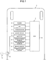
- FIG. 1 is a schematic configuration diagram of a hybrid vehicle including a travel control device according to an embodiment.
- FIG. 2 is a schematic configuration diagram of an ECU and a navigation device in the travel control device according to the embodiment.
- a travel control device 1 according to the embodiment is installed in, what is called, a hybrid vehicle 2 having driving sources for running, which rotationally drive the driving wheels in combination of an engine 5 and an MG 6 as a motor.
- the travel control device 1 includes an Electronic Control Unit 50 (ECU). Then, the travel control device 1 selects the travel plans of the hybrid vehicle 2 by causing the ECU 50 to control the engine 5, the MG 6, and a transmission 7, which is described below, corresponding to the conditions.
- ECU Electronic Control Unit 50
- the travel control device 1 of the embodiment selects the travel plans based on an expected charging time at a destination where a battery 9 can be charged. This allows the travel control device 1 to further reduce the total running cost of the hybrid vehicle 2.
- the travel control device 1 of the embodiment selects a first travel plan that inhibits an HV mode in a state of high load of the HV mode among an EV mode and the HV mode, which are described below, and a second travel plan that allows the HV mode in a state of high load.
- the hybrid vehicle 2 includes the engine 5 as an internal combustion engine, the motor generator (hereinafter referred to as "MG") 6, the transmission 7, a brake device 8, and the battery 9, and the like. Also, the hybrid vehicle 2 includes a vehicle speed sensor 10, an accelerator sensor 11, a brake sensor 12, a navigation device 13, and the like.
- MG motor generator
- the hybrid vehicle 2 includes a vehicle speed sensor 10, an accelerator sensor 11, a brake sensor 12, a navigation device 13, and the like.
- the engine 5 applies a driving force for running to the wheels of the hybrid vehicle 2 in response to an acceleration request by a driver, for example, a pressing operation of an accelerator pedal.
- the engine 5 consumes a fuel to generate an engine torque as a torque of an internal combustion engine for a driving force for running to apply the driving wheels of the hybrid vehicle 2.
- the engine 5 is a heat engine that burns a fuel to generate heat energy and output the heat energy in the form of mechanical energy such as a torque
- the examples of the heat engine include a gasoline engine, a diesel engine, and an LPG engine.
- the engine 5 includes, for example, a fuel injection device, an ignition device, and a throttle valve device, which are not illustrated, and these devices are electrically coupled to the ECU 50 and are controlled by the ECU 50.
- the ECU 50 controls an output torque of the engine 5. Note that a driving force for running generated by the engine 5 may be used for electric generation in the MG 6.
- the MG 6 applies a driving force for running to the wheels of the hybrid vehicle 2 in response to an acceleration request by a driver, for example, the pressing operation of the accelerator pedal.
- the MG 6 converts electric energy into mechanical power to generate a motor torque as a driving force for running applied to the driving wheels of the hybrid vehicle 2.
- the MG 6 is, what is called, a rotating electrical machine including a stator as a stationary member and a rotor as a rotation member.
- the MG 6 is an electric motor that converts electric energy into mechanical power, as well as an electric generator that converts mechanical power into electric energy to recover the electric energy.
- the MG 6 has a function as an electric motor that operates by providing electric power, and converts the electric energy into mechanical energy to output (power running function), and a function as an electric generator that converts mechanical energy into electric energy (regenerative function).
- the MG 6 is electrically coupled to the ECU 50 via an inverter or similar component that performs conversion between a direct current and an alternating current, and is controlled by the ECU 50.
- the ECU 50 controls an output torque and an electric generation amount of the MG 6 via the inverter.
- the transmission 7 is a power transmission that shifts gears and transmits a rotary driving force from the engine 5 or the MG 6 to the side of the driving wheels of the hybrid vehicle 2.
- the transmission 7 may be, what is called, a manual transmission (MT), or also may be, what is called, an automatic transmission such as a stepped automatic transmission (AT), a continuously variable transmission (CVT), a multi-mode manual transmission (MMT), a sequential manual transmission (SMT), a dual clutch transmission (DCT).
- the transmission 7 will be described herein, for example, as a continuously variable transmission (CVT) having a planetary gear mechanism or similar mechanism.
- the transmission 7 includes the transmission actuator and similar component electrically coupled to the ECU 50, and is controlled by the ECU 50.
- the brake device 8 applies a braking force to the wheels of the hybrid vehicle 2 in response to a brake request operation by a driver, for example, the pressing operation of a brake pedal.
- the brake device 8 generates a predetermined friction force (friction resistance force) between friction elements such as brake pads and brake discs to provide a braking force to the wheels rotatably supported to a vehicle body of the hybrid vehicle 2. This allows the brake device 8 to generate a braking force at contact surfaces between the wheels of the hybrid vehicle 2 and the road surface to brake the hybrid vehicle 2.
- the brake device 8 includes a brake actuator or similar component electrically coupled to the ECU 50, and is controlled by the ECU 50.
- the battery 9 is an electric storage device that can store electric power (electric storage) and discharge the stored electric power.
- the battery 9 is electrically coupled to the ECU 50, and outputs signals related to various kinds of information to the ECU 50.
- the battery 9 according to the embodiment detects a state of charge (hereinafter, referred to as SOC), and outputs the detected result to the ECU 50.
- SOC a state of charge
- the battery 9 is coupled to the MG 6 via an inverter (not illustrated). Further, the battery 9 is connected to a connector 15 via an inverter, and the connector 15 is to be connected to an external power source 14 such as a domestic power source.
- the battery 9 is supplied with electric power from the external power source 14 such as the domestic power source via the connector 15 and the inverter. This allows to charge the battery 9 with the electric power from the external power source 14 by connecting the connector 15 to the external power source 14.
- the external power source 14 refers to a power source that can charge the battery 9 via the connector 15 or similar member.
- the MG 6 works as an electric motor
- the electric power stored in the battery 9 is supplied to the MG 6 via the inverter, and the supplied electric power is converted into a driving force for running of the hybrid vehicle 2 to be output.
- the MG 6 works as an electric generator
- the electric power is generated by an input driving force, and the generated electric power is stored in the battery 9 via the inverter.
- the MG 6 can brake the rotation of the rotor with rotation resistance generated on the rotor (regeneration brake).
- the MG 6 can generate a motor regeneration torque, which is a negative motor torque of the rotor by regenerating the electric power, resulting in providing a braking force to the driving wheels of the hybrid vehicle 2.
- a mechanical power is input to the MG 6 from the driving wheels, causing the MG 6 to generate electric energy by regeneration, accordingly the hybrid vehicle 2 can recover movement energy of the hybrid vehicle 2 as electric energy. Then, with this, mechanical power (negative motor torque) generated on the rotor of the MG 6 is transmitted to the driving wheels, accordingly the hybrid vehicle 2 can perform regeneration braking with the MG 6.
- the hybrid vehicle 2 when a regeneration amount (electric generation amount) by the MG 6 is relatively small, the generated braking force is relatively small, then a deceleration degree applied to the hybrid vehicle 2 becomes relatively small.
- a regeneration amount (electric generation amount) by the MG 6 when a regeneration amount (electric generation amount) by the MG 6 is relatively large, the generated braking force is relatively large, then a decelerate degree applied to the hybrid vehicle 2 becomes relatively large.
- the vehicle speed sensor 10, the accelerator sensor 11, and the brake sensor 12 are state detecting devices that detect a running state of the hybrid vehicle 2 or an input to the hybrid vehicle 2 by a driver (driver input), that is, a state quantity and a physical quantity related to actual operation of the hybrid vehicle 2 by a driver.
- the vehicle speed sensor 10 detects a vehicle speed of the hybrid vehicle 2 (hereinafter, sometimes referred to as "vehicle speed").
- the accelerator sensor 11 detects an accelerator opening degree, which is an operation amount (depressed amount) of the accelerator pedal by a driver.
- the brake sensor 12 detects an operation amount (depressed amount) of the brake pedal, for example, a master cylinder pressure or similar pressure.
- the vehicle speed sensor 10, the accelerator sensor 11, and the brake sensor 12 are electrically coupled to the ECU 50, and output the detected signals to the ECU 50.
- the navigation device 13 is a device that detects a current position and obtains the position of the hybrid vehicle 2 in map information, which is stored in advance, and calculates a travel route to a destination as well as displays the position of the hybrid vehicle 2 and the travel route to the destination or similar information.
- the navigation device 13 is on-vehicle equipment installed in the hybrid vehicle 2, and includes a global positioning system (hereinafter referred to as "GPS") device 16, a database 17, a destination setting unit 18, a travel route setting unit 19, a display device 20, and an input device 21 as illustrated in FIG. 2 .
- GPS global positioning system
- the GPS device 16 is a device that detects the current position of the hybrid vehicle 2.
- the GPS device 16 receives GPS signals output from a GPS satellite, and performs positioning and operation of GPS information (X-coordinate: X, Y-coordinate: Y), which is the location information of the hybrid vehicle 2 based on the received GPS signal.
- the GPS device 16 is electrically coupled to the ECU 50, and outputs signals related to the GPS information to the ECU 50.
- the database 17 stores various kinds of information.
- the database 17 includes map information including road information, and various kinds of information or learning information or similar information obtained in actual travel of the hybrid vehicle 2. Examples of the road information include road gradient information, road surface condition information, road shape information, speed limit information, road curvature (curve) information, stop sign information, stop line position information or similar information.
- the ECU 50 appropriately refers to the information stored in the database 17, and reads out required information. Note that although the database 17 is illustrated as being installed in the hybrid vehicle 2, the database 17 is not limited to this and can be placed in a location outside of the hybrid vehicle 2, such as an information center, the ECU 50 may appropriately refer to the information stored in the database 17, and read out required information via, for example, wireless communications (not illustrated). Also, the database 17 of the embodiment stores, as map information, information indicative of whether or not the external power source 14 that can charge the battery 9 exists at a destination set by the destination setting unit 18.
- the destination setting unit 18 is a unit to which information indicative of the location of a destination for the hybrid vehicle 2 is input via the input device 21 by a vehicle occupant or similar member.
- the ECU 50 appropriately refers to the information indicative of the location of the destination stored in the destination setting unit 18 to read out the information. Note that, for example, when a predetermined time elapsed since the input of the information indicative of the location of the destination from the input device 21, the information indicative of the location of the destination input into the destination setting unit 18 is deleted if the destination is reached, the destination being input from the input device 21 based on the information from the GPS device 16.
- the travel route setting unit 19 calculates a travel route to the destination based on the GPS information (X-coordinate: X, Y-coordinate: Y), which is current location information of the hybrid vehicle 2 obtained by the GPS device 16 by performing positioning and operation, and the map information stored in the database 17 or similar information, and stores the travel route.
- the ECU 50 appropriately refers to the information indicative of the travel route to the destination stored in the travel route setting unit 19 to read out the information.
- the display device 20 includes a display device (visual information display device) and a speaker (sound output device), and a similar device, which are placed in an occupant compartment of the hybrid vehicle 2.
- the display device 20 displays a position of the hybrid vehicle 2, a destination, and a travel route with map information, and similar information.
- the input device 21 includes operating buttons or similar member, which are placed in the occupant compartment of the hybrid vehicle 2. The input device 21 is used for inputting the destination or similar information.
- the ECU 50 is a control unit that integrally controls the whole hybrid vehicle 2 and is configured as, for example, an electronic circuit mainly includes well-known microcomputers including a CPU, a ROM, a RAM and an interface.
- the ECU 50 receives the detection results detected by the vehicle speed sensor 10, the accelerator sensor 11, and the brake sensor 12, the GPS information obtained by the GPS device 16, various kinds of information stored in the database 17, drive signals of each portion, electrical signals corresponding to a control command or similar command.
- the ECU 50 controls the engine 5, the MG 6, the transmission 7, the brake device 8, and the battery 9, and the like in response to these input electrical signals, and similar signals.
- the ECU 50 performs drive control of the engine 5, drive control of the MG 6, transmission control of the transmission 7, and brake control of the brake device 8 or similar control based on an accelerator opening degree, and a vehicle speed or similar information. Also, for example, the ECU 50 uses the engine 5 and the MG 6 in combination or selects one of the engine 5 and the MG 6 to use in response to the driving conditions to realize various travel modes such as the EV mode and the HV mode.
- the EV mode refers to a travel mode that causes the hybrid vehicle 2 to travel with a driving force for running only by the MG 6, while the HV mode refers to a travel mode that causes the hybrid vehicle 2 to travel with a driving force for running at least by the engine 5.
- the ECU 50 operates the engine 5 in an efficient state as much as possible, while causing the MG 6, which is a rotating electrical machine, to compensate a surplus or shortage of a driving force for running or an engine brake force, as well as to perform regeneration of energy during decelerating to improve fuel economy.
- the ECU 50 can detect an ON/OFF state of accelerator operation, which is an acceleration request to the hybrid vehicle 2 by a driver, and an accelerator opening degree based on the detected result by the accelerator sensor 11. Similar to this, for example, the ECU 50 can detect an ON/OFF state of brake operation, which is a brake request to the hybrid vehicle 2, based on the detected result by the brake sensor 12. Note that a state where an accelerator operation by a driver is OFF refers to a state where the driver stops acceleration request operation to the hybrid vehicle 2, while a state where an accelerator operation by a driver is ON refers to a state where the driver continues acceleration request operation to the hybrid vehicle 2.
- a state where a brake operation by a driver is OFF refers to a state where the driver stops brake request operation to the hybrid vehicle 2
- a state where a brake operation by a driver is ON refers to a state where the driver continues brake request operation to the hybrid vehicle 2.
- the ECU 50 detects a driver request power based on an accelerator opening degree.
- the travel control device 1 includes the above-described ECU 50. Also, in the present invention, the travel control device 1 may include the navigation device 13, various kinds of sensors that detect a state of the vehicle, and various kinds of information acquisition units that provide surrounding information in addition to the ECU 50. The travel control device 1 can further reduce the total running cost of the hybrid vehicle 2 by causing the ECU 50 to select the first travel plan or the second travel plan depending on the conditions, and select the EV mode and the HV mode in each travel plan.
- the ECU 50 determines whether or not the electric power required for travelling to the destination only by the EV mode (corresponding to required travel energy) is below a current remaining capacity of the battery 9 based on the travel route calculated by the travel route setting unit 19.
- the travel control device 1 refers to information stored in the database 17.
- the travel control device 1 estimates expected charging time at the destination based on the information stored in a storage unit 51, which is described below, when the external power source 14 exists at the destination, and selects the first travel plan when the estimated expected charging time is long.
- the travel control device 1 selects the second travel plan in the case of anyone of when the required travel energy is determined not to be below the currently remaining capacity, or when no external power source 14 exists at the destination, or when the estimated expected charging time is short.
- the ECU 50 includes the storage unit 51, a first estimating unit 52 (corresponding to a required travel energy estimating unit), a determination unit 53, a second estimating unit 54 (corresponding to a charging time estimating unit), and a drive switching unit 55.
- the storage unit 51 refers to information of the navigation device 13, and classifies and stores times actually taken to charge the battery 9 from the external power source 14 (hereinafter referred to as actual charging time) for each location where the hybrid vehicle 2 stops.
- the storage unit 51 appropriately accumulates and stores an actual charging time for each location where the hybrid vehicle 2 stops. Specifically, when the actual charging times in the past at a vehicle stop location A where an X-coordinate is x1 and a Y-coordinate is y1 are A1, A2, ... An, and the actual charging times in the past at a vehicle stop location B, where an X-coordinate is x2 and a Y-coordinate is y2 are B1, B2, ... Bn, the storage unit 51 associates the vehicle stop location A with the actual charging times A1, A2, ... An , and store them, and also associates the vehicle stop location B with the actual charging times B1, B2, ... Bn, and stores them.
- the first estimating unit 52 estimates an electric power (corresponding to required travel energy) required for travelling to a destination, which is input from the input device 21, only by the EV mode based on a travel route calculated by the travel route setting unit 19.
- the determination unit 53 refers to information in the destination setting unit 18 of the navigation device 13 to determine whether or not a destination is set in the destination setting unit 18. Also, the determination unit 53 determines whether or not the electric power corresponding to the required travel energy estimated by the first estimating unit 52 is below the current remaining capacity of the battery 9. Further, the determination unit 53 refers to the information in the destination setting unit 18 of the navigation device 13 and the database 17 to determine whether or not the external power source 14 exists at the destination.
- the second estimating unit 54 estimates an expected charging time (a time in which the battery 9 can be charged from the external power source 14 and the hybrid vehicle 2 stops) at the destination, which is input from the input device 21, based on the actual charging time for each vehicle stop location of the hybrid vehicle 2 stored in the storage unit 51. Specifically, the second estimating unit 54 calculates, from the information accumulated in the storage unit 51, an average value of the actual charging times in the past at the destination input from the input device 21, and sets the calculated average value as an expected charging time. For example, when a destination input from the input device 21 is the location A, which is described above, the second estimating unit 54 calculates an average value of charging times A1, A2, ... An in the past stored in the storage unit 51, and sets the calculated average value as an expected charging time.
- an expected charging time a time in which the battery 9 can be charged from the external power source 14 and the hybrid vehicle 2 stops
- the second estimating unit 54 may set a value other than the average value if the setting value can be obtained from the actual charging times A1, A2, ... An in the past or similar time stored in the storage unit 51. Also, if the information accumulated in the storage unit 51 does not include information indicative of actual charging times in the past at the destination input from the input device 21, a default value input in advance will be set as an expected charging time. Note that this default value preferably exceeds a threshold value, which is described below.
- the drive switching unit 55 selects the first travel plan if the expected charging time estimated by the second estimating unit 54 exceeds the threshold value, which is determined in advance. Also, the drive switching unit 55 selects the second travel plan if the estimated expected charging time is equal to or less than the threshold value, which is determined in advance.
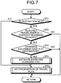
- FIG. 3 is a flowchart for selecting the travel plans of the ECU in the travel control device according to the embodiment.
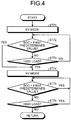
- FIG. 4 is a flowchart of the second travel plan of the ECU in the travel control device according to the embodiment.
- FIG. 5 is a flowchart of the first travel plan of the ECU in the travel control device according to the embodiment.
- the determination unit 53 of the ECU 50 in the travel control device 1 refers to information from the navigation device 13 to determine whether or not the information indicative of the location of a destination is input into the destination setting unit 18 in the step ST1 of FIG. 3 . That is, the determination unit 53 of the ECU 50 in the travel control device 1 determines whether or not the destination is set, and the process proceeds to the step ST2 if the destination is determined to be set, or the process proceeds to the step ST6 if the destination is determined not to be set.
- the activation of the hybrid vehicle 2 refers to a state where the hybrid vehicle 2 can immediately travel by operation of an accelerator pedal after the power supply of the hybrid vehicle 2 is turned on.
- the first estimating unit 52 of the ECU 50 in the travel control device 1 estimates the electric power corresponding to the required travel energy based on the travel route or similar information calculated by the travel route setting unit 19. Then in the step ST2, the determination unit 53 of the ECU 50 in the travel control device 1 determines whether or not the electric power corresponding to the estimated required travel energy is below the current remaining capacity of the battery 9. If the determination unit 53 of the ECU 50 in the travel control device 1 determines that the electric power corresponding to the estimated required travel energy is below the current remaining capacity of the battery 9, the process proceeds to the step ST3, and if determined not to be below, the process proceeds to the step ST7.
- the determination unit 53 of the ECU 50 in the travel control device 1 refers to the information of the navigation device 13 to determine whether or not the external power source 14 exists at the destination set by the destination setting unit 18. If the determination unit 53 of the ECU 50 in the travel control device 1 determines that the external power source 14 exists, the process proceeds to the step ST4, and if the external power source 14 is determined not to exist, the process proceeds to the step ST7.
- the second estimating unit 54 of the ECU 50 in the travel control device 1 estimates the expected charging time at the destination based on, for example, the information accumulated in the storage unit 51, then the process proceeds to the step ST5.
- the drive switching unit 55 of the ECU 50 in the travel control device 1 determines whether or not the expected charging time estimated by the second estimating unit 54 exceeds the threshold value. If the drive switching unit 55 of the ECU 50 in the travel control device 1 determines that the expected charging time exceeds the threshold value, the process proceeds to the step ST6 and selects the first travel plan, and if the expected charging time is determined not to exceed, the process proceeds to the step ST7 and selects the second travel plan.
- the drive switching unit 55 of the ECU 50 in the travel control device 1 selects the EV mode, and stops the engine 5 or keeps a state where the engine 5 stops and the MG 6 operates alone in the step ST71 of FIG. 4 . Then, the drive switching unit 55 of the ECU 50 in the travel control device 1 causes the hybrid vehicle 2 to travel only with a driving force for running by the MG 6, then the process proceeds to the step ST72. In the step ST72, the drive switching unit 55 of the ECU 50 in the travel control device 1 determines whether or not the SOC of the battery 9 is below a first predetermined value, which is determined in advance.
- the process proceeds to the step ST74, and if the SOC of the battery 9 is determined not to be below the first predetermined value, which is determined in advance, the process proceeds to the step ST73.
- the drive switching unit 55 of the ECU 50 in the travel control device 1 determines whether or not the hybrid vehicle 2 is in a state of high load, for example, during high speed running or uphill running, which requires a relatively high drive torque based on the information from the transmission 7, the accelerator sensor 11 and the vehicle speed sensor 10. If the drive switching unit 55 of the travel control device 1 determines that the hybrid vehicle 2 is in a state of high load, the process proceeds to the step ST74, and if the hybrid vehicle 2 is determined not be in a state of high load, the process returns to the step ST72.
- the drive switching unit 55 of the travel control device 1 repeats the step ST72 and the step ST73 and keeps the EV mode to cause the hybrid vehicle 2 to travel with a driving force for running only by the MG 6 until the SOC is determined to be below the first predetermined value, which is determined in advance, or until the hybrid vehicle 2 is determined to be in a state of high load.
- the drive switching unit 55 of the ECU 50 in the travel control device 1 selects the HV mode and operates the engine 5. Then, the drive switching unit 55 of the ECU 50 in the travel control device 1 causes the hybrid vehicle 2 to travel with a driving force for running at least by the engine 5, then the process proceeds to the step ST75. In this way, if the drive switching unit 55 of the ECU 50 in the travel control device 1 determines that the SOC is below the first predetermined value, which is determined in advance, in the step ST72, or determines that the hybrid vehicle 2 is in a state of high load in the step ST73, the process proceeds to the step ST74, and selects the HV mode to cause the hybrid vehicle 2 to travel with a driving force for running at least by the engine 5.
- the drive switching unit 55 of the ECU 50 in the travel control device 1 operates the engine 5 in an efficient state as much as possible, while causing the MG 6 to compensate a surplus or shortage of a driving force for running or an engine brake force based on the information from the transmission 7, the accelerator sensor 11, the brake sensor 12 and the vehicle speed sensor 10. Specifically, the drive switching unit 55 of the ECU 50 in the travel control device 1 causes the MG 6 to perform regeneration braking during decelerating to provide a braking force to the driving wheels of the hybrid vehicle 2, while charging the battery 9 with the electric power generated by the MG 6. In this way, in the step ST74, the drive switching unit 55 of the ECU 50 in the travel control device 1 causes the MG 6 to perform regeneration braking during decelerating to charge the battery 9 to recover the SOC.
- the drive switching unit 55 of the ECU 50 in the travel control device 1 determines whether or not the SOC of the battery 9 is below the first predetermined value, which is determined in advance. If the drive switching unit 55 of the ECU 50 in the travel control device 1 determines that the SOC of the battery 9 is below the first predetermined value, the process repeats the step ST75, and if the SOC of the battery 9 is determined not to be below the first predetermined value, the process proceeds to the step ST76.
- the drive switching unit 55 of the ECU 50 in the travel control device 1 determines whether or not the hybrid vehicle 2 is in a state of high load based on the information from the transmission 7, the accelerator sensor 11, and the vehicle speed sensor 10. If the drive switching unit 55 of the ECU 50 in the travel control device 1 determines that the hybrid vehicle 2 is in a state of high load, the process returns to the step ST75, and if the hybrid vehicle 2 is determined not to be in a state of high load, the process returns to the step ST71.
- the drive switching unit 55 of the ECU 50 in the travel control device 1 repeats the step ST75 and the step ST76, and keeps the HV mode until the SOC is determined not to be below the first predetermined value, and the hybrid vehicle 2 is determined not to be in a state of high load. Also, after selecting the HV mode, if the drive switching unit 55 of the travel control device 1 determines that the SOC is not below the first predetermined value, and the hybrid vehicle 2 is not in a state of high load, the process returns to the step ST71, and selects the EV mode.
- the drive switching unit 55 of the ECU 50 in the travel control device 1 selects the EV mode, and stops the engine 5 or keeps a state where the engine 5 stops and the MG 6 operates alone in the step ST61 of FIG. 5 . Then, the drive switching unit 55 of the ECU 50 in the travel control device 1 causes the hybrid vehicle 2 to travel with a driving force for running only by the MG 6, then the process proceeds to the step ST62. In the step ST62, the drive switching unit 55 of the ECU 50 in the travel control device 1 determines whether or not the SOC of the battery 9 is below a second predetermined value, which is determined in advance.
- the second predetermined value is a value that is different from the above-described first predetermined value, and is substantially smaller than the first predetermined value. If the drive switching unit 55 of the ECU 50 in the travel control device 1 determines that the SOC of the battery 9 is below the second predetermined value, which is determined in advance, the process proceeds to the step ST63, and if the SOC of the battery 9 is determined not to be below the second predetermined value, which is determined in advance, the process repeats the step ST62.
- step ST63 the drive switching unit 55 of the ECU 50 in the travel control device 1 selects the HV mode and operates the engine 5. Then, the drive switching unit 55 of the ECU 50 in the travel control device 1 causes the hybrid vehicle 2 to travel with a driving force for running at least by the engine 5, then the process proceeds to the step ST64. Also in this step ST64, similarly to the above-described step ST74, the drive switching unit 55 of the ECU 50 in the travel control device 1 operates the engine 5 in an efficient state as much as possible, while causing the MG 6 to compensate a surplus or shortage of a driving force for running and an engine brake force, and charges the battery 9 with the electric power generated by the MG 6.
- the drive switching unit 55 of the ECU 50 in the travel control device 1 determines whether or not the SOC of the battery 9 is below the above-described first predetermined value. If the drive switching unit 55 of the ECU 50 in the travel control device 1 determines that the SOC of the battery 9 is below the first predetermined value, the process repeats the step ST64, and if the SOC of the battery 9 is determined not to be below the first predetermined value, the process returns to the step ST61 and selects the EV mode.
- the drive switching unit 55 of the ECU 50 in the travel control device 1 repeats the step ST62, and keeps the EV mode to cause the hybrid vehicle 2 to travel with a driving force for running only by the MG 6 until the SOC is determined to be below the second predetermined value that is substantially smaller than the first predetermined value.
- the drive switching unit 55 of the ECU 50 in the travel control device 1 select the EV mode and the HV mode in such a way as to inhibit frequently using the HV mode during a state of high load to increase the usage frequency of the EV mode more than the second travel plan until reaching the destination by causing the hybrid vehicle 2 to travel with a driving force for running only by the MG 6 until the SOC is determined to be below the second predetermined value that is substantially smaller than the first predetermined value.
- the drive switching unit 55 of the travel control device 1 selects the EV mode and the HV mode in such a way as to increase the usage frequency of the EV mode and suppress the usage frequency of the HV mode during a state of high load until reaching the destination more in the first travel plan where the expected charging time estimated by the second estimating unit 54 is longer than in the second travel plan where the estimated expected charging time is short.
- the first travel plan corresponds to the case where the expected charging time estimated by the second estimating unit 54 is long
- the second travel plan corresponds to the case where the expected charging time estimated by the second estimating unit 54 is short.
- the travel control device 1 of the embodiment increases the usage frequency of the EV mode in the first travel plan in which the expected charging time at the destination where the battery can be charged, which is estimated by the first estimating unit 52, is longer than in the second travel plan in which the expected charging time at the destination is short. Therefore, when the expected charging time at the destination where the battery 9 can be charged is long, the use of the HV mode during a state of high load is inhibited, which causes the hybrid vehicle 2 to travel with a driving force for running by the MG 6, until the SOC goes below the second predetermined value.
- the hybrid vehicle 2 is forced to travel with a driving force for running only by MG 6 even the hybrid vehicle 2 gets in a state of high load on the way to the destination. Therefore, the electric power stored in the battery 9 can be surely used when the hybrid vehicle 2 travels, which can reduce the deterioration of fuel economy due to the drive of the engine 5 and further reduces the total running cost of the hybrid vehicle 2.
- the use of the HV mode during the state of high load is allowed, which can charge the battery 9 on the way to the destination. Accordingly, the charge of the battery 9 can be reduced during travelling after starting the destination, which can reduce the deterioration of fuel economy and further reduce the total running cost of the hybrid vehicle 2.
- the second estimating unit 54 estimates the expected charging time at the destination based on the actual charging time for each vehicle stop location of the hybrid vehicle 2 stored the storage unit 51, which can accurately estimate the expected charging time or a time in which the battery 9 can be charged.
- the electric power stored in the battery 9 can be surely used when the hybrid vehicle 2 travels, which can reduce the deterioration of fuel economy due to the drive of the engine 5 and further reduce the total running cost of the hybrid vehicle 2.
- the drive switching unit 55 selects the first travel plan. Therefore, when the second estimating unit 54 sets the above-described default value as the expected charging time, or when the destination is not set in the destination setting unit 18, the engine 5 is not operated until the SOC goes below the second predetermined value even in a state of high load, which further can reduce the total running cost of the hybrid vehicle 2.
- the second estimating unit 54 sets the above-described default value as the expected charging time, or even when the destination is not set in the destination setting unit 18, if the SOC goes below the second predetermined value, the HV mode is selected to cause the hybrid vehicle 2 to travel with a driving force for running by the engine 5, which can recover the SOC of the battery 9.
- the travel control device 1 of the embodiment selects the first travel plan
- the travel control device 1 does not operate the engine 5 until the SOC goes below the second predetermined value even in a state of high load, which surely allows further reduction in the total running cost of the hybrid vehicle 2.
- the horizontal axis indicates the travel distance of the hybrid vehicle 2
- the vertical axis indicates the SOC of the battery 9.
- the comparative example 1 indicates a conventional example that only selects the second travel plan.
- This example selects the HV mode between the points "a” and “b” since it gets in a state of high load, and also selects the HV mode between the points “d” and “B” since the SOC of this example goes below the first predetermined value, and selects the EV mode in the remaining intervals.
- the comparative example 2 indicates another conventional example that only selects the second travel plan. This example selects the EV mode between the points "0" and "A”, and selects the HV mode between the points "A" and "B” since the SOC of this example goes below the first predetermined value.
- the comparative example 1 is indicated by the one dot chain line in FIG. 6
- the comparative example 2 is indicated by the dotted line in FIG. 6 .
- the present invention 1 indicates the above-described embodiment that selects the first travel plan or the EV mode in all intervals by sufficiently charging the battery at the point "A".
- the present invention 2 indicates the above-described embodiment that does not charge the battery at the point "A”.
- This example selects the first travel plan or the EV mode between the points "0" and "c”, and selects the HV mode between the points "c" and "B” since the SOC of this example goes below the second predetermined value.
- the present invention 1 is indicated by the solid line in FIG. 6
- the present invention 2 is indicated by the two-dot chain line in FIG. 6 .
- FIG. 6 is a diagram describing transitions of the SOC relative to travelling distance of comparative examples and the present invention.
- FIG. 7 is a flowchart for selecting the travel plans of the ECU in the travel control device of the modification according to the embodiment
- FIG. 8 is an explanatory diagram illustrating a map for setting the proportion of the first travel plan of the drive switching unit of the ECU in the travel control device of the modification according to the embodiment. Note that, in the modification, the same reference numerals are given to the components same as those of the above-described embodiment, and description thereof will be omitted.
- the drive switching unit 55 of the ECU 50 in the travel control device 1 sets the proportion of the first travel plan and the second travel plan based on the expected charging time estimated by the second estimating unit 54 in the step ST5a illustrated in FIG. 7 .
- the drive switching unit 55 previously stores a map, illustrated in FIG. 8 , illustrating the relation between the estimated expected charging time and the first travel plan, and reads out, from the map illustrated in FIG. 8 , the proportion of the first travel plan corresponding to the expected charging time estimated by the second estimating unit 54.
- the expected charging times T 1 , T 2 , T 3 , ... T n respectively correspond to proportions R 1 , R 2 , R 3 , ... R n of the first travel plans, and the expected charging times are expressed as T 1 > T 2 > T 3 >, ... >T n , and the proportions of the first travel plans are expressed as R 1 > R 2 > R 3 >, ... > R n .
- the proportion R 1 is 100%
- the proportion R n is 0%.
- the drive switching unit 55 reads out the proportion corresponding to the expected charging time estimated by the second estimating unit 54 from the map illustrated in FIG. 8 .
- the drive switching unit 55 reads out one of the proportions R 1 , R 2 , R 3 , ... R n , which corresponds to one of the expected charging times T 1 , T 2 , T 3 , ... T n , which is closest to the expected charging time estimated by the second estimating unit 54.
- the drive switching unit 55 sets the proportion of the first travel plan as R 1 when the expected charging time estimated by the second estimating unit 54 is longer than the expected charging time T 1 , and sets the proportion of the first travel plan as R n when the expected charging time estimated by the second estimating unit 54 is shorter than the expected charging time T n .
- the drive switching unit 55 divides the distance to the destination into a distance for travelling with the first travel plan and a distance for travelling with the second travel plan depending on the proportion obtained from the map illustrated in FIG. 8 , and causes the hybrid vehicle 2 to travel to the destination with switching the first travel plan and the second travel plan depending on the divided distances.
- the drive switching unit 55 gradually increases the proportion of travelling with the first travel plan as the expected charging time estimated by the second estimating unit 54 becomes long.
- the drive switching unit 55 selects the EV mode and the HV mode in such a way as to increase the usage frequency of the EV mode until reaching to the destination in a case where the expected charging time estimated by the second estimating unit 54 is longer than a case where the expected charging time is short.
- the drive switching unit 55 gradually increases the proportion of travelling with the first travel plan as the expected charging time estimated by the second estimating unit 54 becomes long.
- the drive switching unit 55 selects the EV mode and the HV mode in such a way as to suppress the usage frequency of the HV mode during a state of high load until reaching to the destination in a case where the expected charging time estimated by the second estimating unit 54 is longer than a case where the expected charging time is short.
- the travel control device 1 according to this modification can reduce the deterioration of fuel economy due to the drive of the engine 5 and further reduce the total running cost of the hybrid vehicle 2.
- FIG. 9 a flowchart for selecting the travel plans of an ECU in the travel control device according to the disclosed example 1. Note that, in the disclosed example 1, the same reference numerals are given to the components same as those of the above-described embodiment, and description thereof will be omitted.
- the determination unit 53 of the ECU 50 in the travel control device 1 refers to the information of the navigation device 13 and the information stored in the storage unit 51 to determine whether or not the external power source 14 exists at the destination set by the destination setting unit 18 in the step ST3a.
- the determination unit 53 determines that the battery 9 may be charged if, for example, the external power source 14 exists at the destination, and the battery 9 was charged by the external power source 14 in the past at the location set as the destination.
- the process proceeds to the step ST6, and if the determination unit 53 determines that the battery may not be charged, the process proceeds to the step ST7.
- the determination unit 53 of the ECU 50 in the travel control device 1 determines that the battery 9 may be charged from the external power source 14 at the destination set by the destination setting unit 18, the first travel plan is performed, which can reduce the deterioration of fuel economy due to the drive of the engine 5 and further reduces the total running cost of the hybrid vehicle 2.
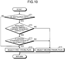
- FIG. 10 is a flowchart for selecting the travel plans of an ECU in the travel control device according to the disclosed example 2. Note that, in the disclosed example 2, the same reference numerals are given to the components same as those of the above-described embodiment, and description thereof will be omitted.
- the process proceeds to the step ST6, and if the external power source 14 is determined not to exist, the process proceeds to the step ST7.
- the determination unit 53 of the ECU 50 in the travel control device 1 determines that the external power source 14 exists at the destination set by the destination setting unit 18, the first travel plan is selected, which can reduce the deterioration of fuel economy due to the drive of the engine 5 and further reduce the total running cost of the hybrid vehicle 2.
- FIG. 11 is a flowchart for selecting the travel plans of an ECU in the travel control device according to the disclosed example 3. Note that, in the disclosed example 3, the same reference numerals are given to the components same as those of the above-described embodiment, and description thereof will be omitted.
- the determination unit 53 of the ECU 50 in the travel control device 1 refers to the information of the storage unit 51 to determines whether or not the battery 9 was charged by the external power source 14 in the past at the destination set by the destination setting unit 18 in the step ST4a illustrated in FIG. 11 , if the determination unit 53 determines that the battery 9 was charged, the process proceeds to the step ST6, if the determination unit 53 determines that the battery 9 was not charged, the process proceeds to the step ST7.
- the first travel plan is selected, which can reduce the deterioration of fuel economy due to the drive of the engine 5 and further reduce the total running cost of the hybrid vehicle 2.
- the travel control device 1 according to, for example, the above-described embodiment of the present invention is not limited to the above-described embodiment.
- the travel control device according to the embodiment can appropriately combines the components of the embodiment and the modification.
- the first predetermined value and the second predetermined value are different from each other and the second predetermined value is smaller than the first predetermined value
- the first predetermined value may be equal to the second predetermined value in the present invention.
- the HV mode is not selected even in a state of high load, which can reduce the deterioration of fuel economy due to the drive of the engine 5 and further reduce the total running cost of the hybrid vehicle 2.
- the MG 6 is used as a motor, which has a power running function and a regenerative function in combination
- the present invention is not limited to this, for example a motor which has a power running function, and a generator which has a regenerative function may be used in combination.
Description
- The present invention relates to a travel control device.
- Conventionally, a travel control device that is installed in a vehicle and controls a travel of the vehicle is known. For example,
Patent Literature 1 discloses a travel control device of a hybrid vehicle that selects, depending on driving conditions, whether travelling with a driving force for running only by a motor, or travelling with a driving force for running at least by an engine in the hybrid vehicle including the motor and the engine as driving sources of the vehicle. - The conventionally used travel control device of a hybrid vehicle described, for example, in the above-described
Patent Literature 1 determines whether a state of charge (hereinafter referred to as SOC) of a battery (also referred to as secondary battery) providing electric power to a motor is a state below a first predetermined value, which is determined in advance, or a state of high load, for example, during high speed running or uphill running, which requires relatively high torque. The travel control device selects to travel with a driving force for running at least by an engine if it is determined to be one of the cases: the SOC is in a state below the first predetermined value, which is determined in advance; and a state of high load, for example, during high speed running or uphill running, which requires relatively high torque. Also, the travel control device selects to travel with a driving force for running only by a motor if it is determined not to be any of the cases: the SOC is in a state below the first predetermined value, which is determined in advance; and a state of high load, for example, in high speed running or uphill running, which requires relatively high torque. - Patent Literature 1: Japanese Patent Application Laid-open No.
2010-000884 - Document
US 2010/0006359 A1 describes a travel control device according to the preamble ofclaim 1. The control device inquires an occupant of the vehicle whether the occupant has an intention to go to a charging location for example at home. If so, the control device sets a target value for the electric power storage device's amount of a state (SOC) to have a value smaller than when the occupant does not have an intention to go to the charging location. -
Document DE 10 2009 028 922 A1 describes a control method for a hybrid vehicle, the method involving recording position data of a traveled path, and detecting the traveled path in a repeated manner by comparing position data of a recorded path and the data of the traveled path. Information of a flow of energy describing consumption/gain of energy along the path during travel on a route and depending on a position recorded with the position data is captured. A combustion engine and an electric motor are utilized to control participation of driving on a recognized path depending on need of energy/energy gain expected along the recognized path using the information. - Document
US 2003/0015358 A1 describes a hybrid vehicle, wherein a point at which an external power supply is installed is registered in map data in a map information device as a base point. An EV running area centered on the aforesaid base point is registered as map data in the aforesaid map information device. When running towards the base point from outside the EV running area, while performing HEV running before arriving in the EV running area, the charge value of the battery is increased beforehand. Hence, when the vehicle enters the EV running area, it switches to EV running. - However, the travel control device described in, for example, the above-described
Patent Literature 1 is desired to further reduce the total running cost of a hybrid vehicle. - The present invention has been made in view of the above-described problem, and one of its objectives is to provide a travel control device that can further reduce the total running cost of a hybrid vehicle. The object is solved by the features of
claim 1. The dependent claims are directed to preferred embodiments of the invention. - The travel control device according to the present invention increases the usage frequency of the EV mode for travelling with a driving force for running only by a motor when an expected charging time at an estimated destination where a battery can be charged is long. Accordingly, the travel control device can successfully reduce the deterioration of fuel economy and further reduce the total running cost of the hybrid vehicle. Brief Description of Drawings
-
-
FIG. 1 is a schematic configuration diagram of a hybrid vehicle including a travel control device according to an embodiment. -
FIG. 2 is a schematic configuration diagram of an ECU and a navigation device in the travel control device according to the embodiment. -
FIG. 3 is a flowchart for selecting travel plans of the ECU in the travel control device according to the embodiment. -
FIG. 4 is a flowchart illustrating a second travel plan of the ECU in the travel control device according to the embodiment. -
FIG. 5 is a flowchart illustrating a first travel plan of the ECU in the travel control device according to the embodiment. -
FIG. 6 is a diagram describing transitions of the SOC relative to the travelling distance of comparative examples and the present invention. -
FIG. 7 is a flowchart for selecting the travel plans of the ECU in the travel control device of a modification according to the embodiment. -
FIG. 8 is an explanatory diagram illustrating a map for setting a proportion of the first travel plan of a drive switching unit of the ECU in the travel control device of the modification according to the embodiment. -
FIG. 9 is a flowchart for selecting the travel plans of an ECU in a travel control device according to a disclosed example 1. -
FIG. 10 is a flowchart for selecting the travel plans of an ECU in a travel control device according to a disclosed example 2. -
FIG. 11 is a flowchart for selecting the travel plans of an ECU in a travel control device according to a disclosed example 3. - The following describes the embodiment according to the present invention with reference to the drawings. Note that the present invention is not limited to the embodiment. Also, the components of the embodiment described below encompass components that can be easily replaced by a person skilled in the art or components that are substantially same.
-
FIG. 1 is a schematic configuration diagram of a hybrid vehicle including a travel control device according to an embodiment.FIG. 2 is a schematic configuration diagram of an ECU and a navigation device in the travel control device according to the embodiment. As illustrated inFIG. 1 , atravel control device 1 according to the embodiment is installed in, what is called, ahybrid vehicle 2 having driving sources for running, which rotationally drive the driving wheels in combination of anengine 5 and an MG 6 as a motor. Thetravel control device 1 includes an Electronic Control Unit 50 (ECU). Then, thetravel control device 1 selects the travel plans of thehybrid vehicle 2 by causing theECU 50 to control theengine 5, the MG 6, and atransmission 7, which is described below, corresponding to the conditions. - The
travel control device 1 of the embodiment selects the travel plans based on an expected charging time at a destination where abattery 9 can be charged. This allows thetravel control device 1 to further reduce the total running cost of thehybrid vehicle 2. Thetravel control device 1 of the embodiment selects a first travel plan that inhibits an HV mode in a state of high load of the HV mode among an EV mode and the HV mode, which are described below, and a second travel plan that allows the HV mode in a state of high load. - Specifically, the
hybrid vehicle 2 includes theengine 5 as an internal combustion engine, the motor generator (hereinafter referred to as "MG") 6, thetransmission 7, abrake device 8, and thebattery 9, and the like. Also, thehybrid vehicle 2 includes avehicle speed sensor 10, anaccelerator sensor 11, abrake sensor 12, anavigation device 13, and the like. - The
engine 5 applies a driving force for running to the wheels of thehybrid vehicle 2 in response to an acceleration request by a driver, for example, a pressing operation of an accelerator pedal. Theengine 5 consumes a fuel to generate an engine torque as a torque of an internal combustion engine for a driving force for running to apply the driving wheels of thehybrid vehicle 2. In a word, theengine 5 is a heat engine that burns a fuel to generate heat energy and output the heat energy in the form of mechanical energy such as a torque, and the examples of the heat engine include a gasoline engine, a diesel engine, and an LPG engine. Theengine 5 includes, for example, a fuel injection device, an ignition device, and a throttle valve device, which are not illustrated, and these devices are electrically coupled to theECU 50 and are controlled by theECU 50. The ECU 50 controls an output torque of theengine 5. Note that a driving force for running generated by theengine 5 may be used for electric generation in the MG 6. - The MG 6 applies a driving force for running to the wheels of the
hybrid vehicle 2 in response to an acceleration request by a driver, for example, the pressing operation of the accelerator pedal. The MG 6 converts electric energy into mechanical power to generate a motor torque as a driving force for running applied to the driving wheels of thehybrid vehicle 2. The MG 6 is, what is called, a rotating electrical machine including a stator as a stationary member and a rotor as a rotation member. The MG 6 is an electric motor that converts electric energy into mechanical power, as well as an electric generator that converts mechanical power into electric energy to recover the electric energy. Namely, theMG 6 has a function as an electric motor that operates by providing electric power, and converts the electric energy into mechanical energy to output (power running function), and a function as an electric generator that converts mechanical energy into electric energy (regenerative function). TheMG 6 is electrically coupled to theECU 50 via an inverter or similar component that performs conversion between a direct current and an alternating current, and is controlled by theECU 50. TheECU 50 controls an output torque and an electric generation amount of theMG 6 via the inverter. - The
transmission 7 is a power transmission that shifts gears and transmits a rotary driving force from theengine 5 or theMG 6 to the side of the driving wheels of thehybrid vehicle 2. Thetransmission 7 may be, what is called, a manual transmission (MT), or also may be, what is called, an automatic transmission such as a stepped automatic transmission (AT), a continuously variable transmission (CVT), a multi-mode manual transmission (MMT), a sequential manual transmission (SMT), a dual clutch transmission (DCT). Thetransmission 7 will be described herein, for example, as a continuously variable transmission (CVT) having a planetary gear mechanism or similar mechanism. Thetransmission 7 includes the transmission actuator and similar component electrically coupled to theECU 50, and is controlled by theECU 50. - The
brake device 8 applies a braking force to the wheels of thehybrid vehicle 2 in response to a brake request operation by a driver, for example, the pressing operation of a brake pedal. Thebrake device 8 generates a predetermined friction force (friction resistance force) between friction elements such as brake pads and brake discs to provide a braking force to the wheels rotatably supported to a vehicle body of thehybrid vehicle 2. This allows thebrake device 8 to generate a braking force at contact surfaces between the wheels of thehybrid vehicle 2 and the road surface to brake thehybrid vehicle 2. Thebrake device 8 includes a brake actuator or similar component electrically coupled to theECU 50, and is controlled by theECU 50. - The
battery 9 is an electric storage device that can store electric power (electric storage) and discharge the stored electric power. Thebattery 9 is electrically coupled to theECU 50, and outputs signals related to various kinds of information to theECU 50. Thebattery 9 according to the embodiment detects a state of charge (hereinafter, referred to as SOC), and outputs the detected result to theECU 50. Note that, in the present invention, the SOC refers to a value, which is obtained by dividing the remaining capacity of thebattery 9 by the full charge capacity of thebattery 9, shown as a percentage indicated by multiplying by 100. That is, the SOC = ((the remaining capacity of the battery 9)/(the full charge capacity of the battery 9)) x 100. - Also, the
battery 9 is coupled to theMG 6 via an inverter (not illustrated). Further, thebattery 9 is connected to aconnector 15 via an inverter, and theconnector 15 is to be connected to anexternal power source 14 such as a domestic power source. Thebattery 9 is supplied with electric power from theexternal power source 14 such as the domestic power source via theconnector 15 and the inverter. This allows to charge thebattery 9 with the electric power from theexternal power source 14 by connecting theconnector 15 to theexternal power source 14. Note that, in the present invention, theexternal power source 14 refers to a power source that can charge thebattery 9 via theconnector 15 or similar member. - When the
MG 6 works as an electric motor, the electric power stored in thebattery 9 is supplied to theMG 6 via the inverter, and the supplied electric power is converted into a driving force for running of thehybrid vehicle 2 to be output. Also, when theMG 6 works as an electric generator, the electric power is generated by an input driving force, and the generated electric power is stored in thebattery 9 via the inverter. At this time, theMG 6 can brake the rotation of the rotor with rotation resistance generated on the rotor (regeneration brake). As a result, during regeneration braking, theMG 6 can generate a motor regeneration torque, which is a negative motor torque of the rotor by regenerating the electric power, resulting in providing a braking force to the driving wheels of thehybrid vehicle 2. That is, a mechanical power is input to theMG 6 from the driving wheels, causing theMG 6 to generate electric energy by regeneration, accordingly thehybrid vehicle 2 can recover movement energy of thehybrid vehicle 2 as electric energy. Then, with this, mechanical power (negative motor torque) generated on the rotor of theMG 6 is transmitted to the driving wheels, accordingly thehybrid vehicle 2 can perform regeneration braking with theMG 6. In this case, in thehybrid vehicle 2, when a regeneration amount (electric generation amount) by theMG 6 is relatively small, the generated braking force is relatively small, then a deceleration degree applied to thehybrid vehicle 2 becomes relatively small. On the other hand, in thishybrid vehicle 2, when a regeneration amount (electric generation amount) by theMG 6 is relatively large, the generated braking force is relatively large, then a decelerate degree applied to thehybrid vehicle 2 becomes relatively large. - The
vehicle speed sensor 10, theaccelerator sensor 11, and thebrake sensor 12 are state detecting devices that detect a running state of thehybrid vehicle 2 or an input to thehybrid vehicle 2 by a driver (driver input), that is, a state quantity and a physical quantity related to actual operation of thehybrid vehicle 2 by a driver. Thevehicle speed sensor 10 detects a vehicle speed of the hybrid vehicle 2 (hereinafter, sometimes referred to as "vehicle speed"). Theaccelerator sensor 11 detects an accelerator opening degree, which is an operation amount (depressed amount) of the accelerator pedal by a driver. Thebrake sensor 12 detects an operation amount (depressed amount) of the brake pedal, for example, a master cylinder pressure or similar pressure. Thevehicle speed sensor 10, theaccelerator sensor 11, and thebrake sensor 12 are electrically coupled to theECU 50, and output the detected signals to theECU 50. - The
navigation device 13 is a device that detects a current position and obtains the position of thehybrid vehicle 2 in map information, which is stored in advance, and calculates a travel route to a destination as well as displays the position of thehybrid vehicle 2 and the travel route to the destination or similar information. Thenavigation device 13 is on-vehicle equipment installed in thehybrid vehicle 2, and includes a global positioning system (hereinafter referred to as "GPS") device 16, a database 17, a destination setting unit 18, a travelroute setting unit 19, a display device 20, and an input device 21 as illustrated inFIG. 2 . - The GPS device 16 is a device that detects the current position of the
hybrid vehicle 2. The GPS device 16 receives GPS signals output from a GPS satellite, and performs positioning and operation of GPS information (X-coordinate: X, Y-coordinate: Y), which is the location information of thehybrid vehicle 2 based on the received GPS signal. The GPS device 16 is electrically coupled to theECU 50, and outputs signals related to the GPS information to theECU 50. - The database 17 stores various kinds of information. The database 17 includes map information including road information, and various kinds of information or learning information or similar information obtained in actual travel of the
hybrid vehicle 2. Examples of the road information include road gradient information, road surface condition information, road shape information, speed limit information, road curvature (curve) information, stop sign information, stop line position information or similar information. TheECU 50 appropriately refers to the information stored in the database 17, and reads out required information. Note that although the database 17 is illustrated as being installed in thehybrid vehicle 2, the database 17 is not limited to this and can be placed in a location outside of thehybrid vehicle 2, such as an information center, theECU 50 may appropriately refer to the information stored in the database 17, and read out required information via, for example, wireless communications (not illustrated). Also, the database 17 of the embodiment stores, as map information, information indicative of whether or not theexternal power source 14 that can charge thebattery 9 exists at a destination set by the destination setting unit 18. - The destination setting unit 18 is a unit to which information indicative of the location of a destination for the
hybrid vehicle 2 is input via the input device 21 by a vehicle occupant or similar member. TheECU 50 appropriately refers to the information indicative of the location of the destination stored in the destination setting unit 18 to read out the information. Note that, for example, when a predetermined time elapsed since the input of the information indicative of the location of the destination from the input device 21, the information indicative of the location of the destination input into the destination setting unit 18 is deleted if the destination is reached, the destination being input from the input device 21 based on the information from the GPS device 16. - the travel
route setting unit 19 calculates a travel route to the destination based on the GPS information (X-coordinate: X, Y-coordinate: Y), which is current location information of thehybrid vehicle 2 obtained by the GPS device 16 by performing positioning and operation, and the map information stored in the database 17 or similar information, and stores the travel route. TheECU 50 appropriately refers to the information indicative of the travel route to the destination stored in the travelroute setting unit 19 to read out the information. - The display device 20 includes a display device (visual information display device) and a speaker (sound output device), and a similar device, which are placed in an occupant compartment of the
hybrid vehicle 2. The display device 20 displays a position of thehybrid vehicle 2, a destination, and a travel route with map information, and similar information. The input device 21 includes operating buttons or similar member, which are placed in the occupant compartment of thehybrid vehicle 2. The input device 21 is used for inputting the destination or similar information. - The
ECU 50 is a control unit that integrally controls the wholehybrid vehicle 2 and is configured as, for example, an electronic circuit mainly includes well-known microcomputers including a CPU, a ROM, a RAM and an interface. TheECU 50 receives the detection results detected by thevehicle speed sensor 10, theaccelerator sensor 11, and thebrake sensor 12, the GPS information obtained by the GPS device 16, various kinds of information stored in the database 17, drive signals of each portion, electrical signals corresponding to a control command or similar command. TheECU 50 controls theengine 5, theMG 6, thetransmission 7, thebrake device 8, and thebattery 9, and the like in response to these input electrical signals, and similar signals. For example, theECU 50 performs drive control of theengine 5, drive control of theMG 6, transmission control of thetransmission 7, and brake control of thebrake device 8 or similar control based on an accelerator opening degree, and a vehicle speed or similar information. Also, for example, theECU 50 uses theengine 5 and theMG 6 in combination or selects one of theengine 5 and theMG 6 to use in response to the driving conditions to realize various travel modes such as the EV mode and the HV mode. - Note that, in the present invention, the EV mode refers to a travel mode that causes the
hybrid vehicle 2 to travel with a driving force for running only by theMG 6, while the HV mode refers to a travel mode that causes thehybrid vehicle 2 to travel with a driving force for running at least by theengine 5. Also, in the HV mode, theECU 50 operates theengine 5 in an efficient state as much as possible, while causing theMG 6, which is a rotating electrical machine, to compensate a surplus or shortage of a driving force for running or an engine brake force, as well as to perform regeneration of energy during decelerating to improve fuel economy. - Also, for example, the
ECU 50 can detect an ON/OFF state of accelerator operation, which is an acceleration request to thehybrid vehicle 2 by a driver, and an accelerator opening degree based on the detected result by theaccelerator sensor 11. Similar to this, for example, theECU 50 can detect an ON/OFF state of brake operation, which is a brake request to thehybrid vehicle 2, based on the detected result by thebrake sensor 12. Note that a state where an accelerator operation by a driver is OFF refers to a state where the driver stops acceleration request operation to thehybrid vehicle 2, while a state where an accelerator operation by a driver is ON refers to a state where the driver continues acceleration request operation to thehybrid vehicle 2. Similar to this, a state where a brake operation by a driver is OFF refers to a state where the driver stops brake request operation to thehybrid vehicle 2, while a state where a brake operation by a driver is ON refers to a state where the driver continues brake request operation to thehybrid vehicle 2. Also, theECU 50 detects a driver request power based on an accelerator opening degree. - Note that, in this embodiment, the
travel control device 1 includes the above-describedECU 50. Also, in the present invention, thetravel control device 1 may include thenavigation device 13, various kinds of sensors that detect a state of the vehicle, and various kinds of information acquisition units that provide surrounding information in addition to theECU 50. Thetravel control device 1 can further reduce the total running cost of thehybrid vehicle 2 by causing theECU 50 to select the first travel plan or the second travel plan depending on the conditions, and select the EV mode and the HV mode in each travel plan. - Schematically explaining, when a destination is set in the destination setting unit 18, the
ECU 50 determines whether or not the electric power required for travelling to the destination only by the EV mode (corresponding to required travel energy) is below a current remaining capacity of thebattery 9 based on the travel route calculated by the travelroute setting unit 19. When the required electric power is determined to be below the current remaining capacity of thebattery 9, thetravel control device 1 refers to information stored in the database 17. Then, thetravel control device 1 estimates expected charging time at the destination based on the information stored in a storage unit 51, which is described below, when theexternal power source 14 exists at the destination, and selects the first travel plan when the estimated expected charging time is long. Thetravel control device 1 selects the second travel plan in the case of anyone of when the required travel energy is determined not to be below the currently remaining capacity, or when noexternal power source 14 exists at the destination, or when the estimated expected charging time is short. - The following describes an exemplary configuration of the
ECU 50 with reference toFIG. 2 . As illustrated inFIG. 2 , theECU 50 includes the storage unit 51, a first estimating unit 52 (corresponding to a required travel energy estimating unit), a determination unit 53, a second estimating unit 54 (corresponding to a charging time estimating unit), and adrive switching unit 55. - The storage unit 51 refers to information of the
navigation device 13, and classifies and stores times actually taken to charge thebattery 9 from the external power source 14 (hereinafter referred to as actual charging time) for each location where thehybrid vehicle 2 stops. The storage unit 51 appropriately accumulates and stores an actual charging time for each location where thehybrid vehicle 2 stops. Specifically, when the actual charging times in the past at a vehicle stop location A where an X-coordinate is x1 and a Y-coordinate is y1 are A1, A2, ... An, and the actual charging times in the past at a vehicle stop location B, where an X-coordinate is x2 and a Y-coordinate is y2 are B1, B2, ... Bn, the storage unit 51 associates the vehicle stop location A with the actual charging times A1, A2, ... An , and store them, and also associates the vehicle stop location B with the actual charging times B1, B2, ... Bn, and stores them. - The
first estimating unit 52 estimates an electric power (corresponding to required travel energy) required for travelling to a destination, which is input from the input device 21, only by the EV mode based on a travel route calculated by the travelroute setting unit 19. - The determination unit 53 refers to information in the destination setting unit 18 of the
navigation device 13 to determine whether or not a destination is set in the destination setting unit 18. Also, the determination unit 53 determines whether or not the electric power corresponding to the required travel energy estimated by thefirst estimating unit 52 is below the current remaining capacity of thebattery 9. Further, the determination unit 53 refers to the information in the destination setting unit 18 of thenavigation device 13 and the database 17 to determine whether or not theexternal power source 14 exists at the destination. - The second estimating unit 54 estimates an expected charging time (a time in which the
battery 9 can be charged from theexternal power source 14 and thehybrid vehicle 2 stops) at the destination, which is input from the input device 21, based on the actual charging time for each vehicle stop location of thehybrid vehicle 2 stored in the storage unit 51. Specifically, the second estimating unit 54 calculates, from the information accumulated in the storage unit 51, an average value of the actual charging times in the past at the destination input from the input device 21, and sets the calculated average value as an expected charging time. For example, when a destination input from the input device 21 is the location A, which is described above, the second estimating unit 54 calculates an average value of charging times A1, A2, ... An in the past stored in the storage unit 51, and sets the calculated average value as an expected charging time. Also, in the present invention, the second estimating unit 54 may set a value other than the average value if the setting value can be obtained from the actual charging times A1, A2, ... An in the past or similar time stored in the storage unit 51. Also, if the information accumulated in the storage unit 51 does not include information indicative of actual charging times in the past at the destination input from the input device 21, a default value input in advance will be set as an expected charging time. Note that this default value preferably exceeds a threshold value, which is described below. - The
drive switching unit 55 selects the first travel plan if the expected charging time estimated by the second estimating unit 54 exceeds the threshold value, which is determined in advance. Also, thedrive switching unit 55 selects the second travel plan if the estimated expected charging time is equal to or less than the threshold value, which is determined in advance. - The following describes an exemplary process of the ECU in the travel control device according to the embodiment with reference to
FIG. 3 through FIG. 5 .FIG. 3 is a flowchart for selecting the travel plans of the ECU in the travel control device according to the embodiment.FIG. 4 is a flowchart of the second travel plan of the ECU in the travel control device according to the embodiment.FIG. 5 is a flowchart of the first travel plan of the ECU in the travel control device according to the embodiment. - After the
hybrid vehicle 2 is activated, the determination unit 53 of theECU 50 in thetravel control device 1 refers to information from thenavigation device 13 to determine whether or not the information indicative of the location of a destination is input into the destination setting unit 18 in the step ST1 ofFIG. 3 . That is, the determination unit 53 of theECU 50 in thetravel control device 1 determines whether or not the destination is set, and the process proceeds to the step ST2 if the destination is determined to be set, or the process proceeds to the step ST6 if the destination is determined not to be set. Note that, in the present invention, the activation of thehybrid vehicle 2 refers to a state where thehybrid vehicle 2 can immediately travel by operation of an accelerator pedal after the power supply of thehybrid vehicle 2 is turned on. - In the step ST2, the
first estimating unit 52 of theECU 50 in thetravel control device 1 estimates the electric power corresponding to the required travel energy based on the travel route or similar information calculated by the travelroute setting unit 19. Then in the step ST2, the determination unit 53 of theECU 50 in thetravel control device 1 determines whether or not the electric power corresponding to the estimated required travel energy is below the current remaining capacity of thebattery 9. If the determination unit 53 of theECU 50 in thetravel control device 1 determines that the electric power corresponding to the estimated required travel energy is below the current remaining capacity of thebattery 9, the process proceeds to the step ST3, and if determined not to be below, the process proceeds to the step ST7. - In the step ST3, the determination unit 53 of the
ECU 50 in thetravel control device 1 refers to the information of thenavigation device 13 to determine whether or not theexternal power source 14 exists at the destination set by the destination setting unit 18. If the determination unit 53 of theECU 50 in thetravel control device 1 determines that theexternal power source 14 exists, the process proceeds to the step ST4, and if theexternal power source 14 is determined not to exist, the process proceeds to the step ST7. - In the step ST4, the second estimating unit 54 of the
ECU 50 in thetravel control device 1 estimates the expected charging time at the destination based on, for example, the information accumulated in the storage unit 51, then the process proceeds to the step ST5. In the step ST5, thedrive switching unit 55 of theECU 50 in thetravel control device 1 determines whether or not the expected charging time estimated by the second estimating unit 54 exceeds the threshold value. If thedrive switching unit 55 of theECU 50 in thetravel control device 1 determines that the expected charging time exceeds the threshold value, the process proceeds to the step ST6 and selects the first travel plan, and if the expected charging time is determined not to exceed, the process proceeds to the step ST7 and selects the second travel plan. - If the second travel plan is selected in the step ST7, the
drive switching unit 55 of theECU 50 in thetravel control device 1 selects the EV mode, and stops theengine 5 or keeps a state where theengine 5 stops and theMG 6 operates alone in the step ST71 ofFIG. 4 . Then, thedrive switching unit 55 of theECU 50 in thetravel control device 1 causes thehybrid vehicle 2 to travel only with a driving force for running by theMG 6, then the process proceeds to the step ST72. In the step ST72, thedrive switching unit 55 of theECU 50 in thetravel control device 1 determines whether or not the SOC of thebattery 9 is below a first predetermined value, which is determined in advance. If thedrive switching unit 55 of thetravel control device 1 determines the SOC of thebattery 9 is below the first predetermined value, which is determined in advance, the process proceeds to the step ST74, and if the SOC of thebattery 9 is determined not to be below the first predetermined value, which is determined in advance, the process proceeds to the step ST73. - In the step ST73, the
drive switching unit 55 of theECU 50 in thetravel control device 1 determines whether or not thehybrid vehicle 2 is in a state of high load, for example, during high speed running or uphill running, which requires a relatively high drive torque based on the information from thetransmission 7, theaccelerator sensor 11 and thevehicle speed sensor 10. If thedrive switching unit 55 of thetravel control device 1 determines that thehybrid vehicle 2 is in a state of high load, the process proceeds to the step ST74, and if thehybrid vehicle 2 is determined not be in a state of high load, the process returns to the step ST72. In this way, thedrive switching unit 55 of thetravel control device 1 repeats the step ST72 and the step ST73 and keeps the EV mode to cause thehybrid vehicle 2 to travel with a driving force for running only by theMG 6 until the SOC is determined to be below the first predetermined value, which is determined in advance, or until thehybrid vehicle 2 is determined to be in a state of high load. - In the step ST74, the
drive switching unit 55 of theECU 50 in thetravel control device 1 selects the HV mode and operates theengine 5. Then, thedrive switching unit 55 of theECU 50 in thetravel control device 1 causes thehybrid vehicle 2 to travel with a driving force for running at least by theengine 5, then the process proceeds to the step ST75. In this way, if thedrive switching unit 55 of theECU 50 in thetravel control device 1 determines that the SOC is below the first predetermined value, which is determined in advance, in the step ST72, or determines that thehybrid vehicle 2 is in a state of high load in the step ST73, the process proceeds to the step ST74, and selects the HV mode to cause thehybrid vehicle 2 to travel with a driving force for running at least by theengine 5. Also, in the step ST74, thedrive switching unit 55 of theECU 50 in thetravel control device 1 operates theengine 5 in an efficient state as much as possible, while causing theMG 6 to compensate a surplus or shortage of a driving force for running or an engine brake force based on the information from thetransmission 7, theaccelerator sensor 11, thebrake sensor 12 and thevehicle speed sensor 10. Specifically, thedrive switching unit 55 of theECU 50 in thetravel control device 1 causes theMG 6 to perform regeneration braking during decelerating to provide a braking force to the driving wheels of thehybrid vehicle 2, while charging thebattery 9 with the electric power generated by theMG 6. In this way, in the step ST74, thedrive switching unit 55 of theECU 50 in thetravel control device 1 causes theMG 6 to perform regeneration braking during decelerating to charge thebattery 9 to recover the SOC. - In the step ST75, the
drive switching unit 55 of theECU 50 in thetravel control device 1 determines whether or not the SOC of thebattery 9 is below the first predetermined value, which is determined in advance. If thedrive switching unit 55 of theECU 50 in thetravel control device 1 determines that the SOC of thebattery 9 is below the first predetermined value, the process repeats the step ST75, and if the SOC of thebattery 9 is determined not to be below the first predetermined value, the process proceeds to the step ST76. - In the step ST76, the
drive switching unit 55 of theECU 50 in thetravel control device 1 determines whether or not thehybrid vehicle 2 is in a state of high load based on the information from thetransmission 7, theaccelerator sensor 11, and thevehicle speed sensor 10. If thedrive switching unit 55 of theECU 50 in thetravel control device 1 determines that thehybrid vehicle 2 is in a state of high load, the process returns to the step ST75, and if thehybrid vehicle 2 is determined not to be in a state of high load, the process returns to the step ST71. In this way, after selecting the HV mode, thedrive switching unit 55 of theECU 50 in thetravel control device 1 repeats the step ST75 and the step ST76, and keeps the HV mode until the SOC is determined not to be below the first predetermined value, and thehybrid vehicle 2 is determined not to be in a state of high load. Also, after selecting the HV mode, if thedrive switching unit 55 of thetravel control device 1 determines that the SOC is not below the first predetermined value, and thehybrid vehicle 2 is not in a state of high load, the process returns to the step ST71, and selects the EV mode. - If the first travel plan is selected in the step ST6, the
drive switching unit 55 of theECU 50 in thetravel control device 1 selects the EV mode, and stops theengine 5 or keeps a state where theengine 5 stops and theMG 6 operates alone in the step ST61 ofFIG. 5 . Then, thedrive switching unit 55 of theECU 50 in thetravel control device 1 causes thehybrid vehicle 2 to travel with a driving force for running only by theMG 6, then the process proceeds to the step ST62. In the step ST62, thedrive switching unit 55 of theECU 50 in thetravel control device 1 determines whether or not the SOC of thebattery 9 is below a second predetermined value, which is determined in advance. Note that the second predetermined value is a value that is different from the above-described first predetermined value, and is substantially smaller than the first predetermined value. If thedrive switching unit 55 of theECU 50 in thetravel control device 1 determines that the SOC of thebattery 9 is below the second predetermined value, which is determined in advance, the process proceeds to the step ST63, and if the SOC of thebattery 9 is determined not to be below the second predetermined value, which is determined in advance, the process repeats the step ST62. - In the step ST63, the
drive switching unit 55 of theECU 50 in thetravel control device 1 selects the HV mode and operates theengine 5. Then, thedrive switching unit 55 of theECU 50 in thetravel control device 1 causes thehybrid vehicle 2 to travel with a driving force for running at least by theengine 5, then the process proceeds to the step ST64. Also in this step ST64, similarly to the above-described step ST74, thedrive switching unit 55 of theECU 50 in thetravel control device 1 operates theengine 5 in an efficient state as much as possible, while causing theMG 6 to compensate a surplus or shortage of a driving force for running and an engine brake force, and charges thebattery 9 with the electric power generated by theMG 6. - In the step ST64, the
drive switching unit 55 of theECU 50 in thetravel control device 1 determines whether or not the SOC of thebattery 9 is below the above-described first predetermined value. If thedrive switching unit 55 of theECU 50 in thetravel control device 1 determines that the SOC of thebattery 9 is below the first predetermined value, the process repeats the step ST64, and if the SOC of thebattery 9 is determined not to be below the first predetermined value, the process returns to the step ST61 and selects the EV mode. - In this way, in the first travel plan, the
drive switching unit 55 of theECU 50 in thetravel control device 1 repeats the step ST62, and keeps the EV mode to cause thehybrid vehicle 2 to travel with a driving force for running only by theMG 6 until the SOC is determined to be below the second predetermined value that is substantially smaller than the first predetermined value. That is, thedrive switching unit 55 of theECU 50 in thetravel control device 1 select the EV mode and the HV mode in such a way as to inhibit frequently using the HV mode during a state of high load to increase the usage frequency of the EV mode more than the second travel plan until reaching the destination by causing thehybrid vehicle 2 to travel with a driving force for running only by theMG 6 until the SOC is determined to be below the second predetermined value that is substantially smaller than the first predetermined value. In this way, thedrive switching unit 55 of thetravel control device 1 selects the EV mode and the HV mode in such a way as to increase the usage frequency of the EV mode and suppress the usage frequency of the HV mode during a state of high load until reaching the destination more in the first travel plan where the expected charging time estimated by the second estimating unit 54 is longer than in the second travel plan where the estimated expected charging time is short. Note that, in this embodiment, the first travel plan corresponds to the case where the expected charging time estimated by the second estimating unit 54 is long, and the second travel plan corresponds to the case where the expected charging time estimated by the second estimating unit 54 is short. - The
travel control device 1 of the embodiment increases the usage frequency of the EV mode in the first travel plan in which the expected charging time at the destination where the battery can be charged, which is estimated by thefirst estimating unit 52, is longer than in the second travel plan in which the expected charging time at the destination is short. Therefore, when the expected charging time at the destination where thebattery 9 can be charged is long, the use of the HV mode during a state of high load is inhibited, which causes thehybrid vehicle 2 to travel with a driving force for running by theMG 6, until the SOC goes below the second predetermined value. Accordingly, unless the SOC goes below the second predetermined value, thehybrid vehicle 2 is forced to travel with a driving force for running only byMG 6 even thehybrid vehicle 2 gets in a state of high load on the way to the destination. Therefore, the electric power stored in thebattery 9 can be surely used when thehybrid vehicle 2 travels, which can reduce the deterioration of fuel economy due to the drive of theengine 5 and further reduces the total running cost of thehybrid vehicle 2. - Also, when the expected charging time at the destination where the
battery 9 can be charged is short, the use of the HV mode during the state of high load is allowed, which can charge thebattery 9 on the way to the destination. Accordingly, the charge of thebattery 9 can be reduced during travelling after starting the destination, which can reduce the deterioration of fuel economy and further reduce the total running cost of thehybrid vehicle 2. - Further, the second estimating unit 54 estimates the expected charging time at the destination based on the actual charging time for each vehicle stop location of the
hybrid vehicle 2 stored the storage unit 51, which can accurately estimate the expected charging time or a time in which thebattery 9 can be charged. - Also, since the second predetermined value is set smaller than the first predetermined value, in the first travel plan, the electric power stored in the
battery 9 can be surely used when thehybrid vehicle 2 travels, which can reduce the deterioration of fuel economy due to the drive of theengine 5 and further reduce the total running cost of thehybrid vehicle 2. - Further, when the second estimating unit 54 estimates the above-described default value as the expected charging time, or when the destination is not set in the destination setting unit 18, the
drive switching unit 55 selects the first travel plan. Therefore, when the second estimating unit 54 sets the above-described default value as the expected charging time, or when the destination is not set in the destination setting unit 18, theengine 5 is not operated until the SOC goes below the second predetermined value even in a state of high load, which further can reduce the total running cost of thehybrid vehicle 2. Also, even when the second estimating unit 54 sets the above-described default value as the expected charging time, or even when the destination is not set in the destination setting unit 18, if the SOC goes below the second predetermined value, the HV mode is selected to cause thehybrid vehicle 2 to travel with a driving force for running by theengine 5, which can recover the SOC of thebattery 9. - Thus, as illustrated in
FIG. 6 , when thetravel control device 1 of the embodiment selects the first travel plan, thetravel control device 1 does not operate theengine 5 until the SOC goes below the second predetermined value even in a state of high load, which surely allows further reduction in the total running cost of thehybrid vehicle 2. Note that, inFIG. 6 , the horizontal axis indicates the travel distance of thehybrid vehicle 2, while the vertical axis indicates the SOC of thebattery 9. The comparative example 1 indicates a conventional example that only selects the second travel plan. This example selects the HV mode between the points "a" and "b" since it gets in a state of high load, and also selects the HV mode between the points "d" and "B" since the SOC of this example goes below the first predetermined value, and selects the EV mode in the remaining intervals. The comparative example 2 indicates another conventional example that only selects the second travel plan. This example selects the EV mode between the points "0" and "A", and selects the HV mode between the points "A" and "B" since the SOC of this example goes below the first predetermined value. The comparative example 1 is indicated by the one dot chain line inFIG. 6 , while the comparative example 2 is indicated by the dotted line inFIG. 6 . Also, thepresent invention 1 indicates the above-described embodiment that selects the first travel plan or the EV mode in all intervals by sufficiently charging the battery at the point "A". Thepresent invention 2 indicates the above-described embodiment that does not charge the battery at the point "A". This example selects the first travel plan or the EV mode between the points "0" and "c", and selects the HV mode between the points "c" and "B" since the SOC of this example goes below the second predetermined value. Thepresent invention 1 is indicated by the solid line inFIG. 6 , and thepresent invention 2 is indicated by the two-dot chain line inFIG. 6 . Note thatFIG. 6 is a diagram describing transitions of the SOC relative to travelling distance of comparative examples and the present invention. - The following describes a modification of the
travel control device 1 according to the embodiment of the present invention.FIG. 7 is a flowchart for selecting the travel plans of the ECU in the travel control device of the modification according to the embodiment, andFIG. 8 is an explanatory diagram illustrating a map for setting the proportion of the first travel plan of the drive switching unit of the ECU in the travel control device of the modification according to the embodiment. Note that, in the modification, the same reference numerals are given to the components same as those of the above-described embodiment, and description thereof will be omitted. - In this modification, the
drive switching unit 55 of theECU 50 in thetravel control device 1 sets the proportion of the first travel plan and the second travel plan based on the expected charging time estimated by the second estimating unit 54 in the step ST5a illustrated inFIG. 7 . Specifically, for example, thedrive switching unit 55 previously stores a map, illustrated inFIG. 8 , illustrating the relation between the estimated expected charging time and the first travel plan, and reads out, from the map illustrated inFIG. 8 , the proportion of the first travel plan corresponding to the expected charging time estimated by the second estimating unit 54. - In the map illustrated in
FIG. 8 , the expected charging times T1, T2, T3, ... Tn respectively correspond to proportions R1, R2, R3, ... Rn of the first travel plans, and the expected charging times are expressed as T1 > T2 > T3 >, ... >Tn, and the proportions of the first travel plans are expressed as R1 > R2 > R3 >, ... > Rn. In addition, when the expected charging time is T1, the proportion R1 is 100%, and when the expected charging time is Tn, the proportion Rn is 0%. - The
drive switching unit 55 reads out the proportion corresponding to the expected charging time estimated by the second estimating unit 54 from the map illustrated inFIG. 8 . When the expected charging time estimated by the second estimating unit 54 does not match any of the expected charging times T1, T2, T3, ... Tn in the map illustrated inFIG. 8 , thedrive switching unit 55 reads out one of the proportions R1, R2, R3, ... Rn, which corresponds to one of the expected charging times T1, T2, T3, ... Tn, which is closest to the expected charging time estimated by the second estimating unit 54. Also, thedrive switching unit 55 sets the proportion of the first travel plan as R1 when the expected charging time estimated by the second estimating unit 54 is longer than the expected charging time T1, and sets the proportion of the first travel plan as Rn when the expected charging time estimated by the second estimating unit 54 is shorter than the expected charging time Tn. - Then, the
drive switching unit 55 divides the distance to the destination into a distance for travelling with the first travel plan and a distance for travelling with the second travel plan depending on the proportion obtained from the map illustrated inFIG. 8 , and causes thehybrid vehicle 2 to travel to the destination with switching the first travel plan and the second travel plan depending on the divided distances. In this way, in the modification, thedrive switching unit 55 gradually increases the proportion of travelling with the first travel plan as the expected charging time estimated by the second estimating unit 54 becomes long. Thus, thedrive switching unit 55 selects the EV mode and the HV mode in such a way as to increase the usage frequency of the EV mode until reaching to the destination in a case where the expected charging time estimated by the second estimating unit 54 is longer than a case where the expected charging time is short. Also, in the modification, thedrive switching unit 55 gradually increases the proportion of travelling with the first travel plan as the expected charging time estimated by the second estimating unit 54 becomes long. Thus, thedrive switching unit 55 selects the EV mode and the HV mode in such a way as to suppress the usage frequency of the HV mode during a state of high load until reaching to the destination in a case where the expected charging time estimated by the second estimating unit 54 is longer than a case where the expected charging time is short. - Similarly to the
travel control device 1 according to the above-described embodiment, thetravel control device 1 according to this modification can reduce the deterioration of fuel economy due to the drive of theengine 5 and further reduce the total running cost of thehybrid vehicle 2. - The following describes a
travel control device 1 according to a disclosed example 1.FIG. 9 a flowchart for selecting the travel plans of an ECU in the travel control device according to the disclosed example 1. Note that, in the disclosed example 1, the same reference numerals are given to the components same as those of the above-described embodiment, and description thereof will be omitted. - In the disclosed example 1, if the determination unit 53 determines that the electric power corresponding to the estimated required travel energy is below the current remaining capacity of the
battery 9 in the step ST2 illustrated inFIG. 9 , the determination unit 53 of theECU 50 in thetravel control device 1 refers to the information of thenavigation device 13 and the information stored in the storage unit 51 to determine whether or not theexternal power source 14 exists at the destination set by the destination setting unit 18 in the step ST3a. In the step ST3a, the determination unit 53 determines that thebattery 9 may be charged if, for example, theexternal power source 14 exists at the destination, and thebattery 9 was charged by theexternal power source 14 in the past at the location set as the destination. If the determination unit 53 of theECU 50 in thetravel control device 1 determines that thebattery 9 may be charged from theexternal power source 14 at the destination set by the destination setting unit 18 in the step ST3a, the process proceeds to the step ST6, and if the determination unit 53 determines that the battery may not be charged, the process proceeds to the step ST7. - In the disclosed example 1, if the determination unit 53 of the
ECU 50 in thetravel control device 1 determines that thebattery 9 may be charged from theexternal power source 14 at the destination set by the destination setting unit 18, the first travel plan is performed, which can reduce the deterioration of fuel economy due to the drive of theengine 5 and further reduces the total running cost of thehybrid vehicle 2. - The following describes the
travel control device 1 according to a disclosed example 2.FIG. 10 is a flowchart for selecting the travel plans of an ECU in the travel control device according to the disclosed example 2. Note that, in the disclosed example 2, the same reference numerals are given to the components same as those of the above-described embodiment, and description thereof will be omitted. - In the disclosed example 2, if the determination unit 53 of the
ECU 50 in thetravel control device 1 determines that theexternal power source 14 exists at the destination set by the destination setting unit 18 in the step ST3 illustrated inFIG. 10 , the process proceeds to the step ST6, and if theexternal power source 14 is determined not to exist, the process proceeds to the step ST7. - In the disclosed example 2, the determination unit 53 of the
ECU 50 in thetravel control device 1 determines that theexternal power source 14 exists at the destination set by the destination setting unit 18, the first travel plan is selected, which can reduce the deterioration of fuel economy due to the drive of theengine 5 and further reduce the total running cost of thehybrid vehicle 2. - The following describes the
travel control device 1 according to a disclosed example 3.FIG. 11 is a flowchart for selecting the travel plans of an ECU in the travel control device according to the disclosed example 3. Note that, in the disclosed example 3, the same reference numerals are given to the components same as those of the above-described embodiment, and description thereof will be omitted. - In the disclosed example 3, the determination unit 53 of the
ECU 50 in thetravel control device 1 refers to the information of the storage unit 51 to determines whether or not thebattery 9 was charged by theexternal power source 14 in the past at the destination set by the destination setting unit 18 in the step ST4a illustrated inFIG. 11 , if the determination unit 53 determines that thebattery 9 was charged, the process proceeds to the step ST6, if the determination unit 53 determines that thebattery 9 was not charged, the process proceeds to the step ST7. - In the disclosed example 3, if the determination unit 53 of the
ECU 50 in thetravel control device 1 determines that thebattery 9 was charged at the destination set by the destination setting unit 18, the first travel plan is selected, which can reduce the deterioration of fuel economy due to the drive of theengine 5 and further reduce the total running cost of thehybrid vehicle 2. - Note that the
travel control device 1 according to, for example, the above-described embodiment of the present invention is not limited to the above-described embodiment. The travel control device according to the embodiment can appropriately combines the components of the embodiment and the modification. - For example, in the
travel control device 1 according to the above-described embodiment, although the first predetermined value and the second predetermined value are different from each other and the second predetermined value is smaller than the first predetermined value, the first predetermined value may be equal to the second predetermined value in the present invention. Also in this case, when the first travel plan is selected, the HV mode is not selected even in a state of high load, which can reduce the deterioration of fuel economy due to the drive of theengine 5 and further reduce the total running cost of thehybrid vehicle 2. - Also in the above-described embodiment, although the
MG 6 is used as a motor, which has a power running function and a regenerative function in combination, the present invention is not limited to this, for example a motor which has a power running function, and a generator which has a regenerative function may be used in combination. -
- 1
- TRAVEL CONTROL DEVICE
- 2
- HYBRID VEHICLE
- 5
- ENGINE (INTERNAL COMBUSTION ENGINE)
- 6
- MG (MOTOR)
- 9
- BATTERY
- 14
- EXTERNAL POWER SOURCE
- 51
- STORAGE UNIT
- 54
- SECOND ESTIMATING UNIT
- 55
- DRIVE SWITCHING UNIT
Claims (2)
- A travel control device (1) of a hybrid vehicle (2) comprising:a battery (9) configured to be charged with electric power from an external power source;a motor (6) configured to generate a driving force for running with the electric power of the battery (9); andan engine (5) configured to generate a driving force for running, the travel control device (1) being configured to select an EV mode for travelling with a driving force for running only by a motor (6), and an HV mode for travelling with a driving force for running at least by an engine (5),characterized in thatthe travel control device (1) estimates an expected charging time at a set destination where the battery (9) can be charged, and selects the EV mode and the HV mode in such a way as to increase a usage frequency of the EV mode by inhibiting the HV mode during a state of high load until reaching to the destination in a case where the estimated expected charging time is longer than a threshold value as compared to a case where the expected charging time is not longer than the threshold value.
- The travel control device (1) according to claim 1, whereinthe travel control device (1) stores an actual charging time taken for actually charging the battery (9) from the external power source for each vehicle stop location of the hybrid vehicle (2), and estimates the expected charging time based on the stored actual charging time for each vehicle stop location.
Applications Claiming Priority (2)
| Application Number | Priority Date | Filing Date | Title |
|---|---|---|---|
| JP2012014515A JP5609898B2 (en) | 2012-01-26 | 2012-01-26 | Travel control device |
| PCT/JP2012/082107 WO2013111464A1 (en) | 2012-01-26 | 2012-12-11 | Travel control device |
Publications (3)
| Publication Number | Publication Date |
|---|---|
| EP2808218A1 EP2808218A1 (en) | 2014-12-03 |
| EP2808218A4 EP2808218A4 (en) | 2015-07-29 |
| EP2808218B1 true EP2808218B1 (en) | 2017-04-05 |
Family
ID=48873205
Family Applications (1)
| Application Number | Title | Priority Date | Filing Date |
|---|---|---|---|
| EP12866806.8A Active EP2808218B1 (en) | 2012-01-26 | 2012-12-11 | Travel control device |
Country Status (5)
| Country | Link |
|---|---|
| US (1) | US9283953B2 (en) |
| EP (1) | EP2808218B1 (en) |
| JP (1) | JP5609898B2 (en) |
| CN (1) | CN104066636B (en) |
| WO (1) | WO2013111464A1 (en) |
Families Citing this family (17)
| Publication number | Priority date | Publication date | Assignee | Title |
|---|---|---|---|---|
| TWI479772B (en) * | 2013-02-21 | 2015-04-01 | 台達電子工業股份有限公司 | Charging system for electric vehicle and charging method thereof |
| DE102013208320A1 (en) * | 2013-05-07 | 2014-11-13 | Deere & Company | Method for determining a control parameter of a power or torque distribution controller for a hybrid drive of a work machine |
| JP6094675B2 (en) * | 2013-07-11 | 2017-03-15 | トヨタ自動車株式会社 | Hybrid vehicle |
| KR101509965B1 (en) * | 2013-11-11 | 2015-04-07 | 현대자동차주식회사 | Apparatus and Method for charging battery of electric vehicle |
| JP6183244B2 (en) * | 2014-02-24 | 2017-08-23 | トヨタ自動車株式会社 | Movement support apparatus and movement support method |
| JP6201808B2 (en) * | 2014-02-24 | 2017-09-27 | トヨタ自動車株式会社 | Movement support device, movement support method, and driving support system |
| EP3144690B1 (en) * | 2015-09-17 | 2018-07-11 | Volvo Car Corporation | Method and apparatus for determining the status of a battery in a vehicle |
| JP6583244B2 (en) * | 2016-12-19 | 2019-10-02 | トヨタ自動車株式会社 | Control device for hybrid vehicle |
| KR102443338B1 (en) * | 2017-09-12 | 2022-09-15 | 현대자동차주식회사 | Battery charging control method and system |
| JP6992460B2 (en) * | 2017-12-05 | 2022-01-13 | トヨタ自動車株式会社 | Hybrid vehicle and control device mounted on it |
| JP6897528B2 (en) * | 2017-12-05 | 2021-06-30 | トヨタ自動車株式会社 | Hybrid vehicle control device |
| WO2019116588A1 (en) * | 2017-12-15 | 2019-06-20 | 日産自動車株式会社 | Control method for hybrid vehicle and control apparatus for hybrid vehicle |
| JP7020144B2 (en) * | 2018-01-30 | 2022-02-16 | トヨタ自動車株式会社 | Electric vehicle and control method of electric vehicle |
| US11560136B2 (en) | 2018-03-02 | 2023-01-24 | Toyota Jidosha Kabushiki Kaisha | Control device |
| JP6939689B2 (en) * | 2018-04-19 | 2021-09-22 | トヨタ自動車株式会社 | Hybrid vehicle control device |
| JP7067387B2 (en) | 2018-09-21 | 2022-05-16 | トヨタ自動車株式会社 | Hybrid vehicle control device |
| JP7369617B2 (en) | 2019-12-26 | 2023-10-26 | 日産自動車株式会社 | Generator control method and generator control device |
Family Cites Families (12)
| Publication number | Priority date | Publication date | Assignee | Title |
|---|---|---|---|---|
| US6814170B2 (en) * | 2001-07-18 | 2004-11-09 | Nissan Motor Co., Ltd. | Hybrid vehicle |
| JP4517984B2 (en) * | 2005-09-01 | 2010-08-04 | トヨタ自動車株式会社 | Hybrid car |
| JP4202379B2 (en) * | 2006-10-11 | 2008-12-24 | トヨタ自動車株式会社 | HYBRID VEHICLE, HYBRID VEHICLE CONTROL METHOD, PROGRAM FOR CAUSING COMPUTER TO EXECUTE THE CONTROL METHOD, AND COMPUTER-READABLE RECORDING MEDIUM CONTAINING THE PROGRAM |
| JP4692466B2 (en) | 2006-10-20 | 2011-06-01 | トヨタ自動車株式会社 | Control device for hybrid vehicle |
| JP4788643B2 (en) * | 2007-04-23 | 2011-10-05 | 株式会社デンソー | Charge / discharge control device for hybrid vehicle and program for the charge / discharge control device |
| JP5181732B2 (en) * | 2007-05-02 | 2013-04-10 | 日産自動車株式会社 | Hybrid vehicle mode switching control device |
| JP2009234566A (en) * | 2008-03-03 | 2009-10-15 | Nissan Motor Co Ltd | Clutch controller and clutch control method of hybrid vehicle |
| CN101585359B (en) * | 2008-05-22 | 2013-03-06 | 杨伟斌 | Energy management method for electric quantity maintaining stage of external charge type hybrid vehicle |
| JP5029494B2 (en) * | 2008-05-27 | 2012-09-19 | アイシン・エィ・ダブリュ株式会社 | Driving energy learning apparatus, method and program |
| JP4506881B2 (en) * | 2008-06-19 | 2010-07-21 | 株式会社デンソー | Control device for hybrid vehicle |
| US8170737B2 (en) * | 2009-04-30 | 2012-05-01 | GM Global Technology Operations LLC | Method of controlling vehicle powertrain and vehicle control system |
| DE102009028922A1 (en) | 2009-08-27 | 2011-03-03 | Robert Bosch Gmbh | Hybrid vehicle managing method, involves utilizing combustion engine and electric motor to control participation of driving on recognized path depending on need for energy or energy gain expected along path using information |
-
2012
- 2012-01-26 JP JP2012014515A patent/JP5609898B2/en active Active
- 2012-12-11 CN CN201280068090.7A patent/CN104066636B/en active Active
- 2012-12-11 WO PCT/JP2012/082107 patent/WO2013111464A1/en active Application Filing
- 2012-12-11 US US14/374,329 patent/US9283953B2/en active Active
- 2012-12-11 EP EP12866806.8A patent/EP2808218B1/en active Active
Also Published As
| Publication number | Publication date |
|---|---|
| JP2013154664A (en) | 2013-08-15 |
| EP2808218A1 (en) | 2014-12-03 |
| JP5609898B2 (en) | 2014-10-22 |
| CN104066636A (en) | 2014-09-24 |
| CN104066636B (en) | 2015-12-09 |
| WO2013111464A1 (en) | 2013-08-01 |
| US9283953B2 (en) | 2016-03-15 |
| US20150019060A1 (en) | 2015-01-15 |
| EP2808218A4 (en) | 2015-07-29 |
Similar Documents
| Publication | Publication Date | Title |
|---|---|---|
| EP2808218B1 (en) | Travel control device | |
| JP6172367B1 (en) | Control device for autonomous driving vehicle | |
| US9145130B2 (en) | Vehicle travel control device | |
| EP2402195B1 (en) | Indication apparatus for hybrid vehicle | |
| CN103282255B (en) | Vehicle and control method for vehicle | |
| EP3575130A1 (en) | Vehicle control system and method of controlling the same, and braking device | |
| US7266441B2 (en) | System and method for controlling idling stop of hybrid electric vehicle | |
| CN102748154A (en) | Method for operating an automatic start/stop system in a vehicle | |
| CN103857574A (en) | Determining a driving strategy for a vehicle | |
| US9770989B2 (en) | Vehicle display device | |
| CN103328291B (en) | Vehicle and control method for vehicle | |
| CN103328292B (en) | Vehicle and control method for vehicle | |
| CN101298235A (en) | Mode change control system for hybrid vehicle | |
| CN101405173A (en) | Braking strategy for a hybrid drive of a vehicle | |
| JP2014173454A (en) | Control device of idle stop vehicle | |
| CN109532560A (en) | Control method, equipment, storage medium and the device of hybrid vehicle | |
| EP2799303B1 (en) | Deceleration factor estimation apparatus | |
| CN101678756A (en) | Control system for a hybrid propulsion unit for recharging a battery | |
| CN107234961B (en) | Apparatus and method for shift control of vehicle | |
| WO2017086435A1 (en) | Regenerative power amount control system for hybrid vehicle, hybrid vehicle, and regenerative power amount control method for hybrid vehicle | |
| CN108349487B (en) | Hybrid vehicle and control method thereof | |
| JP5334661B2 (en) | Vehicle driving support device | |
| JP2018070135A (en) | Vehicular control apparatus | |
| KR102463198B1 (en) | Apparatus and method for controlling belt of mild hybrid electric vehicle | |
| JP2011166877A (en) | Control unit for vehicle, and control method for vehicle |
Legal Events
| Date | Code | Title | Description |
|---|---|---|---|
| PUAI | Public reference made under article 153(3) epc to a published international application that has entered the european phase |
Free format text: ORIGINAL CODE: 0009012 |
|
| 17P | Request for examination filed |
Effective date: 20140723 |
|
| AK | Designated contracting states |
Kind code of ref document: A1 Designated state(s): AL AT BE BG CH CY CZ DE DK EE ES FI FR GB GR HR HU IE IS IT LI LT LU LV MC MK MT NL NO PL PT RO RS SE SI SK SM TR |
|
| DAX | Request for extension of the european patent (deleted) | ||
| RA4 | Supplementary search report drawn up and despatched (corrected) |
Effective date: 20150629 |
|
| RIC1 | Information provided on ipc code assigned before grant |
Ipc: B60W 10/26 20060101ALI20150623BHEP Ipc: B60L 11/18 20060101ALI20150623BHEP Ipc: B60W 20/00 20060101AFI20150623BHEP |
|
| REG | Reference to a national code |
Ref country code: DE Ref legal event code: R079 Ref document number: 602012030922 Country of ref document: DE Free format text: PREVIOUS MAIN CLASS: B60W0020000000 Ipc: B60W0020130000 |
|
| RIC1 | Information provided on ipc code assigned before grant |
Ipc: B60W 10/06 20060101ALI20160905BHEP Ipc: B60W 20/13 20160101AFI20160905BHEP Ipc: B60W 10/26 20060101ALI20160905BHEP Ipc: B60W 10/08 20060101ALI20160905BHEP Ipc: B60L 11/18 20060101ALI20160905BHEP |
|
| GRAP | Despatch of communication of intention to grant a patent |
Free format text: ORIGINAL CODE: EPIDOSNIGR1 |
|
| INTG | Intention to grant announced |
Effective date: 20161014 |
|
| GRAS | Grant fee paid |
Free format text: ORIGINAL CODE: EPIDOSNIGR3 |
|
| GRAA | (expected) grant |
Free format text: ORIGINAL CODE: 0009210 |
|
| AK | Designated contracting states |
Kind code of ref document: B1 Designated state(s): AL AT BE BG CH CY CZ DE DK EE ES FI FR GB GR HR HU IE IS IT LI LT LU LV MC MK MT NL NO PL PT RO RS SE SI SK SM TR |
|
| REG | Reference to a national code |
Ref country code: GB Ref legal event code: FG4D |
|
| REG | Reference to a national code |
Ref country code: CH Ref legal event code: EP |
|
| REG | Reference to a national code |
Ref country code: AT Ref legal event code: REF Ref document number: 881505 Country of ref document: AT Kind code of ref document: T Effective date: 20170415 |
|
| REG | Reference to a national code |
Ref country code: IE Ref legal event code: FG4D |
|
| REG | Reference to a national code |
Ref country code: DE Ref legal event code: R096 Ref document number: 602012030922 Country of ref document: DE |
|
| REG | Reference to a national code |
Ref country code: NL Ref legal event code: MP Effective date: 20170405 |
|
| REG | Reference to a national code |
Ref country code: LT Ref legal event code: MG4D |
|
| REG | Reference to a national code |
Ref country code: AT Ref legal event code: MK05 Ref document number: 881505 Country of ref document: AT Kind code of ref document: T Effective date: 20170405 |
|
| REG | Reference to a national code |
Ref country code: DE Ref legal event code: R084 Ref document number: 602012030922 Country of ref document: DE |
|
| PG25 | Lapsed in a contracting state [announced via postgrant information from national office to epo] |
Ref country code: NL Free format text: LAPSE BECAUSE OF FAILURE TO SUBMIT A TRANSLATION OF THE DESCRIPTION OR TO PAY THE FEE WITHIN THE PRESCRIBED TIME-LIMIT Effective date: 20170405 |
|
| PG25 | Lapsed in a contracting state [announced via postgrant information from national office to epo] |
Ref country code: NO Free format text: LAPSE BECAUSE OF FAILURE TO SUBMIT A TRANSLATION OF THE DESCRIPTION OR TO PAY THE FEE WITHIN THE PRESCRIBED TIME-LIMIT Effective date: 20170705 Ref country code: ES Free format text: LAPSE BECAUSE OF FAILURE TO SUBMIT A TRANSLATION OF THE DESCRIPTION OR TO PAY THE FEE WITHIN THE PRESCRIBED TIME-LIMIT Effective date: 20170405 Ref country code: FI Free format text: LAPSE BECAUSE OF FAILURE TO SUBMIT A TRANSLATION OF THE DESCRIPTION OR TO PAY THE FEE WITHIN THE PRESCRIBED TIME-LIMIT Effective date: 20170405 Ref country code: HR Free format text: LAPSE BECAUSE OF FAILURE TO SUBMIT A TRANSLATION OF THE DESCRIPTION OR TO PAY THE FEE WITHIN THE PRESCRIBED TIME-LIMIT Effective date: 20170405 Ref country code: GR Free format text: LAPSE BECAUSE OF FAILURE TO SUBMIT A TRANSLATION OF THE DESCRIPTION OR TO PAY THE FEE WITHIN THE PRESCRIBED TIME-LIMIT Effective date: 20170706 Ref country code: AT Free format text: LAPSE BECAUSE OF FAILURE TO SUBMIT A TRANSLATION OF THE DESCRIPTION OR TO PAY THE FEE WITHIN THE PRESCRIBED TIME-LIMIT Effective date: 20170405 Ref country code: LT Free format text: LAPSE BECAUSE OF FAILURE TO SUBMIT A TRANSLATION OF THE DESCRIPTION OR TO PAY THE FEE WITHIN THE PRESCRIBED TIME-LIMIT Effective date: 20170405 |
|
| PG25 | Lapsed in a contracting state [announced via postgrant information from national office to epo] |
Ref country code: LV Free format text: LAPSE BECAUSE OF FAILURE TO SUBMIT A TRANSLATION OF THE DESCRIPTION OR TO PAY THE FEE WITHIN THE PRESCRIBED TIME-LIMIT Effective date: 20170405 Ref country code: PL Free format text: LAPSE BECAUSE OF FAILURE TO SUBMIT A TRANSLATION OF THE DESCRIPTION OR TO PAY THE FEE WITHIN THE PRESCRIBED TIME-LIMIT Effective date: 20170405 Ref country code: RS Free format text: LAPSE BECAUSE OF FAILURE TO SUBMIT A TRANSLATION OF THE DESCRIPTION OR TO PAY THE FEE WITHIN THE PRESCRIBED TIME-LIMIT Effective date: 20170405 Ref country code: IS Free format text: LAPSE BECAUSE OF FAILURE TO SUBMIT A TRANSLATION OF THE DESCRIPTION OR TO PAY THE FEE WITHIN THE PRESCRIBED TIME-LIMIT Effective date: 20170805 Ref country code: BG Free format text: LAPSE BECAUSE OF FAILURE TO SUBMIT A TRANSLATION OF THE DESCRIPTION OR TO PAY THE FEE WITHIN THE PRESCRIBED TIME-LIMIT Effective date: 20170705 Ref country code: SE Free format text: LAPSE BECAUSE OF FAILURE TO SUBMIT A TRANSLATION OF THE DESCRIPTION OR TO PAY THE FEE WITHIN THE PRESCRIBED TIME-LIMIT Effective date: 20170405 |
|
| REG | Reference to a national code |
Ref country code: DE Ref legal event code: R097 Ref document number: 602012030922 Country of ref document: DE |
|
| PG25 | Lapsed in a contracting state [announced via postgrant information from national office to epo] |
Ref country code: CZ Free format text: LAPSE BECAUSE OF FAILURE TO SUBMIT A TRANSLATION OF THE DESCRIPTION OR TO PAY THE FEE WITHIN THE PRESCRIBED TIME-LIMIT Effective date: 20170405 Ref country code: EE Free format text: LAPSE BECAUSE OF FAILURE TO SUBMIT A TRANSLATION OF THE DESCRIPTION OR TO PAY THE FEE WITHIN THE PRESCRIBED TIME-LIMIT Effective date: 20170405 Ref country code: DK Free format text: LAPSE BECAUSE OF FAILURE TO SUBMIT A TRANSLATION OF THE DESCRIPTION OR TO PAY THE FEE WITHIN THE PRESCRIBED TIME-LIMIT Effective date: 20170405 Ref country code: SK Free format text: LAPSE BECAUSE OF FAILURE TO SUBMIT A TRANSLATION OF THE DESCRIPTION OR TO PAY THE FEE WITHIN THE PRESCRIBED TIME-LIMIT Effective date: 20170405 Ref country code: RO Free format text: LAPSE BECAUSE OF FAILURE TO SUBMIT A TRANSLATION OF THE DESCRIPTION OR TO PAY THE FEE WITHIN THE PRESCRIBED TIME-LIMIT Effective date: 20170405 |
|
| PLBE | No opposition filed within time limit |
Free format text: ORIGINAL CODE: 0009261 |
|
| STAA | Information on the status of an ep patent application or granted ep patent |
Free format text: STATUS: NO OPPOSITION FILED WITHIN TIME LIMIT |
|
| PG25 | Lapsed in a contracting state [announced via postgrant information from national office to epo] |
Ref country code: SM Free format text: LAPSE BECAUSE OF FAILURE TO SUBMIT A TRANSLATION OF THE DESCRIPTION OR TO PAY THE FEE WITHIN THE PRESCRIBED TIME-LIMIT Effective date: 20170405 Ref country code: IT Free format text: LAPSE BECAUSE OF FAILURE TO SUBMIT A TRANSLATION OF THE DESCRIPTION OR TO PAY THE FEE WITHIN THE PRESCRIBED TIME-LIMIT Effective date: 20170405 |
|
| 26N | No opposition filed |
Effective date: 20180108 |
|
| PG25 | Lapsed in a contracting state [announced via postgrant information from national office to epo] |
Ref country code: SI Free format text: LAPSE BECAUSE OF FAILURE TO SUBMIT A TRANSLATION OF THE DESCRIPTION OR TO PAY THE FEE WITHIN THE PRESCRIBED TIME-LIMIT Effective date: 20170405 |
|
| REG | Reference to a national code |
Ref country code: CH Ref legal event code: PL |
|
| GBPC | Gb: european patent ceased through non-payment of renewal fee |
Effective date: 20171211 |
|
| REG | Reference to a national code |
Ref country code: IE Ref legal event code: MM4A |
|
| PG25 | Lapsed in a contracting state [announced via postgrant information from national office to epo] |
Ref country code: LU Free format text: LAPSE BECAUSE OF NON-PAYMENT OF DUE FEES Effective date: 20171211 Ref country code: MT Free format text: LAPSE BECAUSE OF NON-PAYMENT OF DUE FEES Effective date: 20171211 |
|
| REG | Reference to a national code |
Ref country code: FR Ref legal event code: ST Effective date: 20180831 |
|
| REG | Reference to a national code |
Ref country code: BE Ref legal event code: MM Effective date: 20171231 |
|
| PG25 | Lapsed in a contracting state [announced via postgrant information from national office to epo] |
Ref country code: IE Free format text: LAPSE BECAUSE OF NON-PAYMENT OF DUE FEES Effective date: 20171211 Ref country code: FR Free format text: LAPSE BECAUSE OF NON-PAYMENT OF DUE FEES Effective date: 20180102 |
|
| PG25 | Lapsed in a contracting state [announced via postgrant information from national office to epo] |
Ref country code: CH Free format text: LAPSE BECAUSE OF NON-PAYMENT OF DUE FEES Effective date: 20171231 Ref country code: LI Free format text: LAPSE BECAUSE OF NON-PAYMENT OF DUE FEES Effective date: 20171231 Ref country code: BE Free format text: LAPSE BECAUSE OF NON-PAYMENT OF DUE FEES Effective date: 20171231 Ref country code: GB Free format text: LAPSE BECAUSE OF NON-PAYMENT OF DUE FEES Effective date: 20171211 |
|
| PG25 | Lapsed in a contracting state [announced via postgrant information from national office to epo] |
Ref country code: MC Free format text: LAPSE BECAUSE OF FAILURE TO SUBMIT A TRANSLATION OF THE DESCRIPTION OR TO PAY THE FEE WITHIN THE PRESCRIBED TIME-LIMIT Effective date: 20170405 Ref country code: HU Free format text: LAPSE BECAUSE OF FAILURE TO SUBMIT A TRANSLATION OF THE DESCRIPTION OR TO PAY THE FEE WITHIN THE PRESCRIBED TIME-LIMIT; INVALID AB INITIO Effective date: 20121211 |
|
| PG25 | Lapsed in a contracting state [announced via postgrant information from national office to epo] |
Ref country code: CY Free format text: LAPSE BECAUSE OF FAILURE TO SUBMIT A TRANSLATION OF THE DESCRIPTION OR TO PAY THE FEE WITHIN THE PRESCRIBED TIME-LIMIT Effective date: 20170405 |
|
| PG25 | Lapsed in a contracting state [announced via postgrant information from national office to epo] |
Ref country code: MK Free format text: LAPSE BECAUSE OF FAILURE TO SUBMIT A TRANSLATION OF THE DESCRIPTION OR TO PAY THE FEE WITHIN THE PRESCRIBED TIME-LIMIT Effective date: 20170405 |
|
| PG25 | Lapsed in a contracting state [announced via postgrant information from national office to epo] |
Ref country code: TR Free format text: LAPSE BECAUSE OF FAILURE TO SUBMIT A TRANSLATION OF THE DESCRIPTION OR TO PAY THE FEE WITHIN THE PRESCRIBED TIME-LIMIT Effective date: 20170405 |
|
| PG25 | Lapsed in a contracting state [announced via postgrant information from national office to epo] |
Ref country code: PT Free format text: LAPSE BECAUSE OF FAILURE TO SUBMIT A TRANSLATION OF THE DESCRIPTION OR TO PAY THE FEE WITHIN THE PRESCRIBED TIME-LIMIT Effective date: 20170405 |
|
| PG25 | Lapsed in a contracting state [announced via postgrant information from national office to epo] |
Ref country code: AL Free format text: LAPSE BECAUSE OF FAILURE TO SUBMIT A TRANSLATION OF THE DESCRIPTION OR TO PAY THE FEE WITHIN THE PRESCRIBED TIME-LIMIT Effective date: 20170405 |
|
| P01 | Opt-out of the competence of the unified patent court (upc) registered |
Effective date: 20230427 |
|
| PGFP | Annual fee paid to national office [announced via postgrant information from national office to epo] |
Ref country code: DE Payment date: 20231031 Year of fee payment: 12 |