WO2013111439A1 - スライドドアのためのワイヤハーネス配索装置 - Google Patents
スライドドアのためのワイヤハーネス配索装置 Download PDFInfo
- Publication number
- WO2013111439A1 WO2013111439A1 PCT/JP2012/080572 JP2012080572W WO2013111439A1 WO 2013111439 A1 WO2013111439 A1 WO 2013111439A1 JP 2012080572 W JP2012080572 W JP 2012080572W WO 2013111439 A1 WO2013111439 A1 WO 2013111439A1
- Authority
- WO
- WIPO (PCT)
- Prior art keywords
- link member
- wire harness
- cable guide
- sliding door
- adjacent
- Prior art date
- Legal status (The legal status is an assumption and is not a legal conclusion. Google has not performed a legal analysis and makes no representation as to the accuracy of the status listed.)
- Ceased
Links
Images



Classifications
-
- B—PERFORMING OPERATIONS; TRANSPORTING
- B60—VEHICLES IN GENERAL
- B60R—VEHICLES, VEHICLE FITTINGS, OR VEHICLE PARTS, NOT OTHERWISE PROVIDED FOR
- B60R16/00—Electric or fluid circuits specially adapted for vehicles and not otherwise provided for; Arrangement of elements of electric or fluid circuits specially adapted for vehicles and not otherwise provided for
- B60R16/02—Electric or fluid circuits specially adapted for vehicles and not otherwise provided for; Arrangement of elements of electric or fluid circuits specially adapted for vehicles and not otherwise provided for electric constitutive elements
- B60R16/0207—Wire harnesses
- B60R16/0215—Protecting, fastening and routing means therefor
- B60R16/0222—Grommets
-
- B—PERFORMING OPERATIONS; TRANSPORTING
- B60—VEHICLES IN GENERAL
- B60R—VEHICLES, VEHICLE FITTINGS, OR VEHICLE PARTS, NOT OTHERWISE PROVIDED FOR
- B60R16/00—Electric or fluid circuits specially adapted for vehicles and not otherwise provided for; Arrangement of elements of electric or fluid circuits specially adapted for vehicles and not otherwise provided for
- B60R16/02—Electric or fluid circuits specially adapted for vehicles and not otherwise provided for; Arrangement of elements of electric or fluid circuits specially adapted for vehicles and not otherwise provided for electric constitutive elements
- B60R16/023—Electric or fluid circuits specially adapted for vehicles and not otherwise provided for; Arrangement of elements of electric or fluid circuits specially adapted for vehicles and not otherwise provided for electric constitutive elements for transmission of signals between vehicle parts or subsystems
- B60R16/027—Electric or fluid circuits specially adapted for vehicles and not otherwise provided for; Arrangement of elements of electric or fluid circuits specially adapted for vehicles and not otherwise provided for electric constitutive elements for transmission of signals between vehicle parts or subsystems between relatively movable parts of the vehicle, e.g. between steering wheel and column
-
- H—ELECTRICITY
- H02—GENERATION; CONVERSION OR DISTRIBUTION OF ELECTRIC POWER
- H02G—INSTALLATION OF ELECTRIC CABLES OR LINES, OR OF COMBINED OPTICAL AND ELECTRIC CABLES OR LINES
- H02G11/00—Arrangements of electric cables or lines between relatively-movable parts
-
- H—ELECTRICITY
- H02—GENERATION; CONVERSION OR DISTRIBUTION OF ELECTRIC POWER
- H02G—INSTALLATION OF ELECTRIC CABLES OR LINES, OR OF COMBINED OPTICAL AND ELECTRIC CABLES OR LINES
- H02G3/00—Installations of electric cables or lines or protective tubing therefor in or on buildings, equivalent structures or vehicles
- H02G3/02—Details
- H02G3/04—Protective tubing or conduits, e.g. cable ladders or cable troughs
- H02G3/0462—Tubings, i.e. having a closed section
- H02G3/0468—Corrugated
-
- H—ELECTRICITY
- H02—GENERATION; CONVERSION OR DISTRIBUTION OF ELECTRIC POWER
- H02G—INSTALLATION OF ELECTRIC CABLES OR LINES, OR OF COMBINED OPTICAL AND ELECTRIC CABLES OR LINES
- H02G3/00—Installations of electric cables or lines or protective tubing therefor in or on buildings, equivalent structures or vehicles
- H02G3/02—Details
- H02G3/04—Protective tubing or conduits, e.g. cable ladders or cable troughs
- H02G3/0462—Tubings, i.e. having a closed section
- H02G3/0475—Tubings, i.e. having a closed section formed by a succession of articulated units
-
- H—ELECTRICITY
- H02—GENERATION; CONVERSION OR DISTRIBUTION OF ELECTRIC POWER
- H02G—INSTALLATION OF ELECTRIC CABLES OR LINES, OR OF COMBINED OPTICAL AND ELECTRIC CABLES OR LINES
- H02G3/00—Installations of electric cables or lines or protective tubing therefor in or on buildings, equivalent structures or vehicles
- H02G3/02—Details
- H02G3/04—Protective tubing or conduits, e.g. cable ladders or cable troughs
- H02G3/0462—Tubings, i.e. having a closed section
- H02G3/0487—Tubings, i.e. having a closed section with a non-circular cross-section
Definitions
- the present invention relates to a wire harness routing device for a sliding door of an automobile.
- Patent Document 1 is known as a technique for disclosing such a technique.
- a structure in which a wire harness is inserted into a caterpillar-shaped cable guide to protect the wire harness. Both ends of such a cable guide are fixed to the body side and the sliding door side via brackets.
- the cable guide has a structure in which a plurality of link members are connected so as to be sequentially rotatable, and is bent and deformed in accordance with the opening / closing operation of the slide door.
- the body side end of the cable guide is arranged at the step portion of the entrance that is opened and closed by the sliding door. Therefore, when getting on and off with the door fully open, the cable guide may be stepped on by the passenger. When a stepping situation occurs, the cable guide is stressed with tension. Then, since the stress cannot be dispersed in the conventional structure, there is a concern that a portion where the cable guide is stepped on or a connection portion with the door side bracket is damaged.
- the present invention has been completed based on the above circumstances, and is intended for a sliding door that prevents the cable guide from being damaged even when the cable guide is stepped on. It aims at providing a wire harness wiring apparatus.
- the present invention is a wiring harness wiring device that spans between a vehicle body and a slide door, and includes a plurality of link members including a rotation support portion, and the plurality of link members formed by the rotation support portion.
- a cable guide configured to be pivotably connected and a wire harness inserted into the cable guide are provided, and the cable guides can be separated in the longitudinal direction of the cable guide between adjacent link members at the pivot support portion.
- the adjacent link members connected to each other are characterized in that they include ones that are biased toward each other by elastic connection members.
- the wire harness routing device for the sliding door of the present invention may have the following configuration.
- the rotation support part in the adjacent link member connected so as to be separable includes a pin shaft provided on one side of the adjacent link member and a bearing recess provided on the other side.
- the bearing recess is formed to open toward the link member on one side.
- a pair of upper and lower connecting pieces having pin shafts is formed on one side of the adjacent link members so that the connecting pieces are connected to the other side in a state where the adjacent link members are connected to each other. It enters the inside of the link member.
- the cable guide can be separated from the end link member located at the end in the longitudinal direction and exposed from the protective tube and the intermediate link member adjacent to the end link member at the rotation support portion.
- the connecting member is integrally formed from the protective tube and connected to the end link member.
- the elastic connection member has a connection band integrally extending in a loop shape from the end of the protective tube, and this connection band is wound around the outer peripheral surface of the end link member.
- the end link member is formed with a recessed groove into which the connecting band is inserted.
- the elastic connecting member is a spring that connects the link members adjacent to each other in a state where they can be separated from each other in the rotation support portion.
- the present invention includes a cable guide in which adjacent ones can be separated from each other at the rotation support portion. Since the link members in this relationship normally hold a rotatable connection state by the elastic connecting member, the cable guide can perform a normal bending operation as the slide door is opened and closed. However, when the cable guide is stepped on, the cable guide is subjected to a force that is pulled toward the stepped portion, so that the link members are rotated against the elastic force of the elastic connecting member. Is cut off. As a result, stress concentration on a specific part of the cable guide is avoided, so that the cable guide can be protected from damage.
- FIG. 1 The perspective view which shows the whole wiring apparatus which concerns on Embodiment 1.
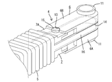
- FIG. 1 The perspective view which shows the door side edge part in a cable guide
- FIG. 1 shows a step portion 1 of an entrance that is opened and closed by a sliding door in an automobile.
- the step portion 1 has a lower step surface 2 having a step with respect to the floor surface.
- a wire harness W for powering an electrical component (not shown) provided in the slide door 3 is installed between the slide door 3 and the vehicle body (rear end portion of the step portion.
- the wire harness W is inserted into the cable guide 4 and protected.
- the cable guide 4 is further inserted into a flexible protective tube 5 made of rubber.
- the cable guide 4 includes an end link member 6 disposed at both ends in the longitudinal direction, and a number of intermediate link members 7 disposed between the both end link members 6. Moreover, a body side bracket (not shown) is attached to the vehicle body side of both ends of the cable guide 4, and a door side bracket 8 is attached to the slide door 3 side as shown in FIGS. 1 and 2. .
- a body-side bracket (not shown) is disposed on the side surface near the rear end of the step portion 1. Similarly, although not shown, the body side bracket and the end of the cable guide 4 are rotatably connected.
- the door-side bracket 8 is composed of two plates, a rear plate 8A and a front plate 8B, which are stacked so as not to be separated from each other.
- a pair of left and right mounting holes 9 are opened on both sides of the door-side bracket 8 in the width direction.
- the door-side bracket 8 is mounted as a whole by screwing bolts or the like into the mounting holes 9 with the back side of the plate in contact with the mounting surface of the slide door 3.
- a vertically long guide cylinder 10 is formed at the upper edge of the rear plate 8A at the center in the width direction so as to protrude toward the front side, and the guide cylinder 10 penetrates in the vertical direction.
- the wire harness W is forced to change upward in the guide tube 10 after passing through the cable guide.
- the end link member 6 located at the door side end of the cable guide 4 is formed in a substantially rectangular tube shape that opens toward the intermediate link member 7 side. Can be inserted through the wire harness W.
- a cylindrical shaft portion 11 leading to the inside is formed on the upper and lower surfaces of the distal end side of the end link member 6 so as to protrude coaxially and has a hole diameter through which the wire harness W can be inserted.
- a connecting piece 12 for connecting the door side bracket 8 and the cable guide 4 so as to be rotatable is provided in the center portion of the front plate 8 ⁇ / b> B as a pair. ing.
- Both connecting pieces 12 have an arc shape and project horizontally toward the front.
- the front and rear plates 8A and 8B of the door-side bracket 8 are overlapped, the side link portions of the cylindrical shaft portions 11 are respectively hooked on the inner sides of the connecting pieces 12, thereby providing an end link member.
- 6 is attached to the door bracket 8 so as to be rotatable around the cylindrical shaft portion 11.
- the guide tube 10 and the tube shaft portion 11 are brought into contact with each other and are in communication with each other.
- the side walls 6A of the end link member 6 are cut off at the opening side so that the upper and lower walls 6B project toward the intermediate link member 7 side.
- the semicircular bearing recessed part 13 is formed in the center part of the edge of each overhanging part.
- the concave groove 14 is formed in the both side walls and the back wall of the end link member 6 over the entire circumferential range.
- the intermediate link member 7 is formed in a rectangular tube shape in which the longitudinal direction of the cable guide 4 penetrates both sides.
- Each intermediate link member 7 has a pair of upper and lower connecting pieces 7A projecting on one end side and a pair of upper and lower connecting receiving pieces 7B projecting on the other end side.
- Both connection receiving pieces 7B are formed so as to be higher by a step corresponding to the thickness of the connection piece 7A with respect to the connection piece 7A.
- the pin shaft 15 is coaxially projected on the outer surface side of both the connecting pieces 7A, the adjacent bearing holes 17 are opened in both the connecting receiving pieces 7B, and the pin shaft 15 of the adjacent intermediate link member 7 is rotatable. It is inserted.
- connection structure between the intermediate link member 7 positioned at the door side end and the door side end link member 6 will be described.
- the end link member 6 on the door side and the intermediate link member 7 adjacent thereto are in a state in which the pin shaft 15 is fitted in the corresponding bearing recess 13 and is rotatably connected (FIGS. 3 and 4). State) and a state (state shown in FIG. 5) which is separated in the longitudinal direction with a rotation support portion constituted by the pin shaft 15 and the bearing recess 13 as a boundary.
- a connecting band 16 extends integrally and in a loop shape at the front edge of the door side end of the protective tube 5. As shown in FIG. 3, the connecting band 16 is hung around in a state of extending along the concave groove 14 of the end link member 6 on the door side. As a result, the end link member 6 on the door side and the intermediate link member 7 adjacent to the end link member 6 are biased toward each other, and the pin shaft 15 and the corresponding bearing recess 13 are respectively aligned. Connected with. However, when a pulling force in the longitudinal direction acts on the intermediate link member 7 such as when the cable guide 4 is stepped on with a foot, the bearing recess 13 to which the pin shaft 15 corresponds against the elastic force of the connecting band 16. The intermediate link member 7 protrudes outward from the end link member 6 and can be in a state of being separated from the end link member 6.
- the pin shaft 15 and the bearing recess 13 are in an aligned state between the door side end link member 6 and the intermediate link member 7 adjacent thereto, so that both can rotate well. it can. Therefore, the cable guide 4 can smoothly perform a predetermined bending operation with the opening / closing operation of the slide door 3.
- connection band 16 is provided on the existing protective tube 5 so as to bias the end link member 6 on the door side and the adjacent intermediate link member 7 toward each other. Therefore, there is also an effect that it is not necessary to increase the number of parts because no special connecting means is required.
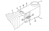
- FIG. 6 shows Embodiment 2 of the present invention.
- the side surfaces of the door-side end link member 6 and the adjacent intermediate link member 7 are connected to each other by a pair of springs 18, thereby urging both in the approaching direction. is there. Since the other configuration is the same as that of the first embodiment, the same reference numerals are given in the drawing and the description will not be repeated.
- the portion where the link member 6, 7 constituting the cable guide 4 is set with a structure that can be separated at the rotation support portion is not necessarily limited to the end portion in the longitudinal direction. It can be set at any position.
- the link member for which the detachable connection relationship is set is limited to that at the end in the longitudinal direction of the cable guide 4.
- the separate spring 18 is used as in the second embodiment, it can be applied between the link members adjacent to each other at any position of the cable guide 4.
- the receiving portion of the end link member 6 is formed in a semicircular shape and can be separated from the intermediate link member 7.
- the receiving portion is a long hole along the longitudinal direction of the cable guide 4.
- the intermediate link member 7 may be connected in a state in which the displacement in the separating direction is allowed but the separation stroke is restricted.
Landscapes
- Engineering & Computer Science (AREA)
- Mechanical Engineering (AREA)
- Electric Cable Arrangement Between Relatively Moving Parts (AREA)
Description
本発明は自動車のスライドドアのためのワイヤハーネス配索装置に関するものである。
従来より、自動車のスライドドア内に装着された電装品への給電を行うために、ボディ側とスライドドア側との間にワイヤハーネスが架設されてきた。そのような技術を開示するものとして、下記特許文献1が知られている。
ここにはワイヤハーネスをキャタピラ状のケーブルガイド内に挿通して、ワイヤハーネスを保護するようにした構造が開示されている。こうしたケーブルガイドの両端部はボディ側とスライドドア側にブラケットを介して固定されている。ケーブルガイドは複数のリンク部材間を順次回動可能に連結した構成であり、スライドドアの開閉動作に伴って屈曲変形するようになっている。
ところで、ケーブルガイドのボディ側端部はスライドドアによって開閉される乗降口のステップ部分に配置されている。したがって、ドアを全開状態にして乗り降りする際に、ケーブルガイドが搭乗者によって踏み付けられてしまうことが起こりうる。踏み付けの事態が生じるとケーブルガイドには引っ張りを伴った応力が生じる。すると、従来の構造では応力を分散させることができないため、ケーブルガイドは踏み付けられた部位やドア側ブラケットとの接続部位等が損傷してしまうことが懸念される。
本発明は上記のような事情に基づいて完成されたものであって、ケーブルガイドが踏み付けられた場合であっても、ケーブルガイドを損傷等に至らせることがないようにしたスライドドアのためのワイヤハーネス配索装置を提供することを目的とする。
本発明は、車両ボディとスライドドアとの間に架け渡される給電用ワイヤハーネスの配索装置であって、回動支持部を備える複数のリンク部材と、複数のリンク部材が回動支持部によって回動可能に連結されて構成されたケーブルガイドと、ケーブルガイド内に挿通されるワイヤハーネスとを備え、ケーブルガイドは、隣接するリンク部材同士が回動支持部においてケーブルガイドの長手方向へ離間可能に連結され、かつ隣接するリンク部材同士は弾性連結部材によって相互に接近する方向に付勢されているものを含むところに特徴を有する。
さらに、本発明のスライドドアのためのワイヤハーネス配索装置は、以下のような構成を有していてもよい。
(1)離間可能に連結された前記隣接するリンク部材における回動支持部は、隣接するリンク部材の一方の側に設けられたピン軸と、他方の側に設けられた軸受け凹部とを備えて構成され、軸受け凹部は、一方の側のリンク部材へ向けて開口して形成されている。これにより、リンク部材同士の切り離しのストロークに制約がなくなるため、ケーブルガイドの保護をより確実に行うことができる。
(2)隣接するリンク部材のうち一方の側には、ピン軸を有する上下一対の連結片が張出し形成され、この連結片は、隣接するリンク部材同士が連結された状態では、他方の側のリンク部材の内方に入り込んでいる。これにより、上下の連結片が他方の側のリンク部材の内部に入り込んだ状態で連結されるため、隣接するリンク部材同士が不用意に外れてしまう事態を回避することができる。
(3)ケーブルガイドは、その長手方向の端部に位置し保護チューブから露出する端部リンク部材とこれに隣接する中間リンク部材との間が回動支持部において離間可能となっており、弾性連結部材は保護チューブから一体に形成されて端部リンク部材に連結されている。これにより、ケーブルガイドを保護する既存の保護チューブを弾性連結部材として利用するようにしたため、部品点数の増加を招かずに済む。
(4)弾性連結部材は、保護チューブの端部からループ状に一体に延出された連結帯を有し、この連結帯が端部リンク部材の外周面に掛け回されている。これにより、中間リンク部材に対し端部リンク部材側へ接近させる方向への付勢力を確実に作用させることができる。
(5)端部リンク部材には連結帯が嵌め入れられる凹溝が凹み形成されている。これにより、連結帯が凹溝によって位置決めされてずれを規制することができる。
(6)弾性連結部材は、回動支持部において離間可能な状態で隣接し合うリンク部材同士を連結するばねである。これにより、隣接するリンク部材を別体のばねによって連結するようにしたため、ばねを取り付けるべきリンク部材を任意に選択することができる。
本発明は、ケーブルガイドの中に隣接するもの同士が回動支持部において離間可能となっているものが含まれている。この関係にあるリンク部材同士は、通常時には弾性連結部材によって回動可能な接続状態が保持されているため、ケーブルガイドはスライドドアの開閉に伴って正規の屈曲動作を行うことができる。しかし、ケーブルガイドの途中が踏み付けられたりすると、ケーブルガイドには踏み付け部位へ向けての引っ張りを伴う力が作用するため、当該リンク部材同士は弾性連結部材の弾性力に抗して回動支持部において切り離される。このことによって、ケーブルガイドにおける特定部位への応力集中が回避されるため、ケーブルガイドを損傷から保護することができる。
<実施形態1>
図1は自動車においてスライドドアによって開閉される乗降口のステップ部1を示している。ステップ部1はフロア面に対して段差をもつ下部ステップ面2が形成されている。スライドドア3と車両ボディ(ステップ部の後端部)との間にはスライドドア3内に装備された電装品(図示しない)への給電のためのワイヤハーネスWが架設されている。ワイヤハーネスWはケーブルガイド4内に挿通されて保護されている。ケーブルガイド4は、さらにゴム製の可撓性保護チューブ5内に挿通されている。
図1は自動車においてスライドドアによって開閉される乗降口のステップ部1を示している。ステップ部1はフロア面に対して段差をもつ下部ステップ面2が形成されている。スライドドア3と車両ボディ(ステップ部の後端部)との間にはスライドドア3内に装備された電装品(図示しない)への給電のためのワイヤハーネスWが架設されている。ワイヤハーネスWはケーブルガイド4内に挿通されて保護されている。ケーブルガイド4は、さらにゴム製の可撓性保護チューブ5内に挿通されている。
ケーブルガイド4は、その長手方向の両端部に配された端部リンク部材6と、この両端部リンク部材6間に配された多数の中間リンク部材7とを備えて構成されている。また、ケーブルガイド4の両端部のうち車両ボディ側にはボディ側ブラケット(図示しない)が取り付けられ、スライドドア3側には図1、図2に示すようにドア側ブラケット8が取り付けられている。
なお、図示しないボディ側ブラケットは、ステップ部1における後端寄り側面部分に配されている。また、同様に図示はされないが、ボディ側ブラケットとケーブルガイド4の端部とは回動可能に連結されている。
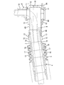
ドア側ブラケット8は図2に示すように、リアプレート8Aとフロントプレート8Bの二枚のプレートよりなり、これらを離間不能に重ね合わせた構成となっている。ドア側ブラケット8の幅方向の両側には左右一対の取付孔9が開口している。ドア側ブラケット8はプレートの背面側をスライドドア3の取付面へ当接させた状態で、両取付孔9へボルト等をねじ込むことによって全体の取付けがなされる。また、リアプレート8Aの上縁であって幅方向中央部には手前側に張り出した状態で縦長のガイド筒10が形成されており、このガイド筒10は上下方向に貫通している。図4、図5に示すように、ワイヤハーネスWはケーブルガイド内を通った後、ガイド筒10においてその配索方向が上方へ強制的に転換されるようになっている。
一方、図3、図4等に示すように、ケーブルガイド4におけるドア側端部に位置する端部リンク部材6は、中間リンク部材7側へ向けて開口する略角筒状に形成され、内部はワイヤハーネスWを挿通可能である。端部リンク部材6における先端側の上下面には内部へ通じる筒軸部11が同軸で突出形成され、ワイヤハーネスWを挿通可能な穴径をもって形成されている。フロントプレート8Bの中央部には、図2及び図4に示すように、ドア側ブラケット8とケーブルガイド4とを回動可能に連結させるための連結片12が上下に対をなして突設されている。両連結片12はそれぞれ円弧形状をなし、前方へ向けて水平に張出している。ドア側ブラケット8のフロント・リアの両プレート8A,8Bが重ね合わされる際に、両連結片12の内側へ両筒軸部11の側面部分をそれぞれ掛け止めるようにすることで、端部リンク部材6がドア側ブラケット8に対し筒軸部11周りに回動可能に取り付けられる。図4、図5に示すように、端部リンク部材6がドア側ブラケット8に取り付けられた状態では、ガイド筒10と筒軸部11とは突き当てられて両者は連通状態となっている。
端部リンク部材6の両側壁6Aは開口側が切り掛かれることで、上下壁6Bが中間リンク部材7側へ向けて張り出すようになっている。そして、それぞれの張出した部分の端縁の中央部には半円状の軸受け凹部13が形成されている。一方、端部リンク部材6の両側壁と奥壁には周方向の全範囲に亘って凹溝14が形成されている。
中間リンク部材7は、ケーブルガイド4の長手方向が双方へ貫通する角筒状に形成されている。各中間リンク部材7は一端側に上下一対の連結片7Aが張出し、他端側には上下一対の連結受け片7Bが張出している。両連結受け片7Bは連結片7Aに対して連結片7Aの厚み分に相当する段差をもって一段高くなるように形成されている。また、両連結片7Aの外面側には同軸でピン軸15が突出し、両連結受け片7Bには隣接する軸受孔17が開口し、隣接する中間リンク部材7のピン軸15が回動可能に嵌め入れられる。このことによって、多数の中間リンク部材7は順次回動可能に連結されて中間リンク部材列を構成する。そして、それぞれの両端部が端部リンク部材6に接続されることによって、ケーブルガイド4全体がスライドドア3の開閉動作に応動してほぼ水平面内で所定の屈曲動作を行うことが可能となる。
なお、図2及び図3等に示すように、ケーブルガイド4が保護チューブ5へ挿通された状態において、ケーブルガイド4のうち端部リンク部材6とこれに隣接する中間リンク部材7の一部は保護チューブ5から露出した状態となっている。
次に、ドア側端部に位置する中間リンク部材7と、ドア側の端部リンク部材6との接続構造について説明する。ドア側の端部リンク部材6とこれに隣接する中間リンク部材7とは、ピン軸15が、対応する軸受け凹部13内に嵌め入れられて回動可能に接続される状態(図3及び図4状態)と、ピン軸15と軸受け凹部13とによって構成される回動支持部を境にして長手方向へ離間する状態(図5状態)との間で変位可能となっている。
一方、保護チューブ5のドア側端部の前縁には連結帯16が一体にかつループ状に延出している。この連結帯16は、図3に示すように、ドア側の端部リンク部材6の凹溝14に沿って伸長した状態で掛け回される。このことにより、ドア側の端部リンク部材6とこれに隣接する中間リンク部材7とは相互に接近する方向に付勢され、ピン軸15と対応する軸受け凹部13とをそれぞれ合芯させた状態で接続される。しかし、ケーブルガイド4が足で踏まれる等、中間リンク部材7に長手方向への引っ張りの力が作用した場合には、連結帯16の弾性力に抗してピン軸15が対応する軸受け凹部13から外方へはみ出して中間リンク部材7が端部リンク部材6から切り離された状態となることができる。
次に、上記のように構成された実施形態1の作用効果を説明する。通常時には、ドア側の端部リンク部材6とこれに隣接する中間リンク部材7との間では、ピン軸15と軸受け凹部13とが合芯状態にあるため、両者は良好に回動することができる。したがって、ケーブルガイド4はスライドドア3の開閉動作に伴って所定の屈曲動作を円滑に行うことができる。
ところで、例えばスライドドア3の全開時において、ケーブルガイド4がその途中の位置で保護チューブ5の上から踏み付けられると、踏み付けられた部位は下方へ変位する。すると、中間リンク部材列のうち最もドア側端部に位置するものには斜め下方への引っ張り力と共にねじれの力が作用する。これにより、ドア側の端部リンク部材6と隣接する中間リンク部材7との間では、図5に示すように、連結帯16の付勢力に抗して上位にあるピン軸15が対応する軸受け凹部13から外方へはみ出した偏心状態となる。このため、中間リンク部材7は端部リンク部材6に対して傾斜した姿勢となる。このように、中間リンク部材7は端部リンク部材6に対して回動支持部において切り離された状態となることから、ケーブルガイド4に作用する応力をこの部分において逃がすことができ、これによってケーブルガイド4が破損に至る事態を未然に回避することができる。
そして、ケーブルガイド4の踏み付け状況が解消されれば、中間リンク部材7と端部リンク部材6との切り離し状況によっては、連結帯16の弾性力によってピン軸15が対応する軸受け凹部13に対して合芯する状態に自動的に復帰させうる。
実施形態1によれば、既存の保護チューブ5に連結帯16を設けて、ドア側の端部リンク部材6と隣接する中間リンク部材7とを互いに接近する方向に付勢するようにしている。したがって、特別な連結手段を必要としない分、部品点数の増加を招かずに済む、という効果も得られる。
<実施形態2>
図6は本発明の実施形態2を示している。本実施形態では、ドア側の端部リンク部材6とこれに隣接する中間リンク部材7との側面同士を一対のばね18によって連結し、これによって両者を接近方向に付勢するようにしたものである。他の構成は実施形態1と同様であるため、図中に同一符号を付すことで重複して説明を行わない。
図6は本発明の実施形態2を示している。本実施形態では、ドア側の端部リンク部材6とこれに隣接する中間リンク部材7との側面同士を一対のばね18によって連結し、これによって両者を接近方向に付勢するようにしたものである。他の構成は実施形態1と同様であるため、図中に同一符号を付すことで重複して説明を行わない。
このような構成によっても、実施形態1と同様の作用効果を得ることができる。加えて、実施形態2によれば次の効果も得ることができる。すなわち、本発明においては、ケーブルガイド4を構成するリンク部材6,7のうち回動支持部において切り離し可能な構造が設定されたものが配される部位は、必ずしも長手方向の端部に限定されず、任意の位置に設定可能である。しかし、実施形態1のように連結帯16を保護チューブ5の端部に形成すると、切り離し可能な接続関係が設定されるリンク部材はケーブルガイド4における長手方向の端部にあるものに限られてしまうが、本実施形態2のように、別体のばね18を利用するものであれば、ケーブルガイド4の任意の位置で隣接し合うリンク部材同士間に適用することができる。
<他の実施形態>
本発明は上記記述及び図面によって説明した実施形態に限定されるものではなく、例えば次のような実施形態も本発明の技術的範囲に含まれる。
(1)上記実施形態ではドア側において、端部リンク部材6と中間リンク部材7とを切り離し可能に接続したが、このような構造をボディ側端部にも併用して設定してもよく、あるいはボディ側端部のみに単独で設定するようにしてもよい。
本発明は上記記述及び図面によって説明した実施形態に限定されるものではなく、例えば次のような実施形態も本発明の技術的範囲に含まれる。
(1)上記実施形態ではドア側において、端部リンク部材6と中間リンク部材7とを切り離し可能に接続したが、このような構造をボディ側端部にも併用して設定してもよく、あるいはボディ側端部のみに単独で設定するようにしてもよい。
(2)上記実施形態では、端部リンク部材6の受け部を半円形状に形成して中間リンク部材7とは切り離し可能としたが、受け部をケーブルガイド4の長手方向に沿った長穴形状にして、中間リンク部材7の離間方向への変位は許容するが切り離しのストロークが規制された状態で接続するようにしてもよい。
4…ケーブルガイド
5…保護チューブ
6…端部リンク部材(隣接するリンク部材)
7…中間リンク部材(隣接するリンク部材)
7A…連結片
8…ドア側ブラケット
13…軸受け凹部(受け部:回動支持部)
14…凹溝
15…ピン軸(回動支持部)
16…連結帯
18…ばね
W…ワイヤハーネス
5…保護チューブ
6…端部リンク部材(隣接するリンク部材)
7…中間リンク部材(隣接するリンク部材)
7A…連結片
8…ドア側ブラケット
13…軸受け凹部(受け部:回動支持部)
14…凹溝
15…ピン軸(回動支持部)
16…連結帯
18…ばね
W…ワイヤハーネス
Claims (7)
- 車両ボディとスライドドアとの間に架け渡される給電用ワイヤハーネスの配索装置であって、
回動支持部を備える複数のリンク部材と、
前記複数のリンク部材が前記回動支持部によって回動可能に連結されて構成されたケーブルガイドと、
前記ケーブルガイド内に挿通されるワイヤハーネスとを備え、
前記ケーブルガイドは、隣接する前記リンク部材同士が前記回動支持部において前記ケーブルガイドの長手方向へ離間可能に連結され、かつ前記隣接する前記リンク部材同士は弾性連結部材によって相互に接近する方向に付勢されているものを含むことを特徴とするスライドドアのためのワイヤハーネス配索装置。 - 離間可能に連結された前記隣接するリンク部材における前記回動支持部は、前記隣接する前記リンク部材の一方の側に設けられたピン軸と、他方の側に設けられた軸受け凹部とを備えて構成され、
前記軸受け凹部は、前記一方の側のリンク部材へ向けて開口して形成されていることを特徴とする請求項1に記載のスライドドアのためのワイヤハーネス配索装置。 - 前記隣接するリンク部材のうち前記一方の側には、前記ピン軸を有する上下一対の連結片が張出し形成され、
この連結片は、前記隣接するリンク部材同士が連結された状態では、前記他方の側のリンク部材の内方に入り込んでいることを特徴とする請求項2に記載のスライドドアのためのワイヤハーネス配索装置。 - 前記ケーブルガイドは、その長手方向の端部に位置し前記保護チューブから露出する端部リンク部材とこれに隣接する中間リンク部材との間が前記回動支持部において離間可能となっており、
前記弾性連結部材は、前記保護チューブから一体に形成されて前記端部リンク部材に連結されていることを特徴とする請求項1ないし請求項3のいずれかに記載のスライドドアのためのワイヤハーネス配索装置。 - 前記弾性連結部材は、前記保護チューブの端部からループ状に一体に延出された連結帯を有し、この連結帯が前記端部リンク部材の外周面に掛け回されていることを特徴とする請求項4に記載のスライドドアのためのワイヤハーネス配索装置。
- 前記端部リンク部材には前記連結帯が嵌め入れられる凹溝が凹み形成されていることを特徴とする請求項5に記載のスライドドアのためのワイヤハーネス配索装置。
- 前記弾性連結部材は、前記回動支持部において離間可能な状態で隣接し合う前記リンク部材同士を連結するばねであることを特徴とする請求項1又は請求項2に記載のスライドドアのためのワイヤハーネス配索装置。
Applications Claiming Priority (2)
| Application Number | Priority Date | Filing Date | Title |
|---|---|---|---|
| JP2012-013859 | 2012-01-26 | ||
| JP2012013859A JP2013151250A (ja) | 2012-01-26 | 2012-01-26 | スライドドアのためのワイヤハーネス配索装置 |
Publications (1)
| Publication Number | Publication Date |
|---|---|
| WO2013111439A1 true WO2013111439A1 (ja) | 2013-08-01 |
Family
ID=48873180
Family Applications (1)
| Application Number | Title | Priority Date | Filing Date |
|---|---|---|---|
| PCT/JP2012/080572 Ceased WO2013111439A1 (ja) | 2012-01-26 | 2012-11-27 | スライドドアのためのワイヤハーネス配索装置 |
Country Status (2)
| Country | Link |
|---|---|
| JP (1) | JP2013151250A (ja) |
| WO (1) | WO2013111439A1 (ja) |
Cited By (1)
| Publication number | Priority date | Publication date | Assignee | Title |
|---|---|---|---|---|
| EP3043434A4 (en) * | 2013-09-06 | 2017-04-26 | Yazaki Corporation | Power feeding structure for sliding door |
Families Citing this family (5)
| Publication number | Priority date | Publication date | Assignee | Title |
|---|---|---|---|---|
| JP5850336B2 (ja) * | 2012-08-21 | 2016-02-03 | 住友電装株式会社 | 電線ガイド体 |
| JP6095118B2 (ja) * | 2013-10-08 | 2017-03-15 | 住友電装株式会社 | 電線ガイド装置 |
| JP6261035B2 (ja) * | 2013-11-21 | 2018-01-17 | 住友電装株式会社 | 電線ガイド装置 |
| JP6488981B2 (ja) * | 2015-10-13 | 2019-03-27 | 住友電装株式会社 | 電線配索装置 |
| JP7004214B2 (ja) * | 2018-03-13 | 2022-01-21 | 住友電装株式会社 | コネクタカバー |
Citations (3)
| Publication number | Priority date | Publication date | Assignee | Title |
|---|---|---|---|---|
| JPH0847153A (ja) * | 1994-06-03 | 1996-02-16 | Wl Gore & Assoc Gmbh | リンクチェーン |
| JP2005090516A (ja) * | 2003-09-11 | 2005-04-07 | Tsubakimoto Chain Co | ケーブル類保護案内装置 |
| JP2011050182A (ja) * | 2009-08-27 | 2011-03-10 | Sumitomo Wiring Syst Ltd | 導電路の屈曲動作ガイド部材及びスライドドア用導電路の屈曲動作ガイド装置 |
-
2012
- 2012-01-26 JP JP2012013859A patent/JP2013151250A/ja active Pending
- 2012-11-27 WO PCT/JP2012/080572 patent/WO2013111439A1/ja not_active Ceased
Patent Citations (3)
| Publication number | Priority date | Publication date | Assignee | Title |
|---|---|---|---|---|
| JPH0847153A (ja) * | 1994-06-03 | 1996-02-16 | Wl Gore & Assoc Gmbh | リンクチェーン |
| JP2005090516A (ja) * | 2003-09-11 | 2005-04-07 | Tsubakimoto Chain Co | ケーブル類保護案内装置 |
| JP2011050182A (ja) * | 2009-08-27 | 2011-03-10 | Sumitomo Wiring Syst Ltd | 導電路の屈曲動作ガイド部材及びスライドドア用導電路の屈曲動作ガイド装置 |
Cited By (1)
| Publication number | Priority date | Publication date | Assignee | Title |
|---|---|---|---|---|
| EP3043434A4 (en) * | 2013-09-06 | 2017-04-26 | Yazaki Corporation | Power feeding structure for sliding door |
Also Published As
| Publication number | Publication date |
|---|---|
| JP2013151250A (ja) | 2013-08-08 |
Similar Documents
| Publication | Publication Date | Title |
|---|---|---|
| WO2013111439A1 (ja) | スライドドアのためのワイヤハーネス配索装置 | |
| US9150168B2 (en) | Sliding door wire harness routing structure | |
| JP5796238B2 (ja) | 車両用ドアの開閉装置 | |
| US7708334B2 (en) | Slide door apparatus for vehicle | |
| JP6404305B2 (ja) | スライドドア装置 | |
| BR112020014708A2 (pt) | Dispositivo de aperto e método de montagem. | |
| JP2020094330A (ja) | ローラユニット | |
| WO2014013964A1 (ja) | アーム給電装置 | |
| JP2010017026A (ja) | スライドドアのハーネス配線装置 | |
| WO2015033889A1 (ja) | スライドドア用給電構造 | |
| JP5850336B2 (ja) | 電線ガイド体 | |
| CN110622376B (zh) | 线束导向件 | |
| JP5359194B2 (ja) | 車両用ドア開閉装置 | |
| JP2010017025A (ja) | スライドドアのハーネス配線装置 | |
| KR20130006165U (ko) | 스핀들 커버 | |
| EP3029231B1 (en) | Door opening/closing device and vehicle door module | |
| JP5027678B2 (ja) | スライド構造体用の給電装置 | |
| JP2021145441A (ja) | 電線ガイド装置 | |
| JP6095118B2 (ja) | 電線ガイド装置 | |
| JP2021145440A (ja) | 電線ガイド装置 | |
| JP2007135299A (ja) | 配線材用の連鎖状プロテクタおよび配線材の保護構造 | |
| EP2198102B1 (en) | Hinge assembly | |
| JP2015101131A (ja) | 電線ガイド装置 | |
| US10465430B2 (en) | Drive device for a vehicle door | |
| JP5434556B2 (ja) | ワイヤーハーネス支持具及び導電経路装置 |
Legal Events
| Date | Code | Title | Description |
|---|---|---|---|
| 121 | Ep: the epo has been informed by wipo that ep was designated in this application |
Ref document number: 12866427 Country of ref document: EP Kind code of ref document: A1 |
|
| NENP | Non-entry into the national phase |
Ref country code: DE |
|
| 122 | Ep: pct application non-entry in european phase |
Ref document number: 12866427 Country of ref document: EP Kind code of ref document: A1 |