WO2013111343A1 - Dispositif de traitement d'informations, système de traitement d'informations, procédé de délivrance de données de communication et programme de délivrance de données de communication - Google Patents
Dispositif de traitement d'informations, système de traitement d'informations, procédé de délivrance de données de communication et programme de délivrance de données de communication Download PDFInfo
- Publication number
- WO2013111343A1 WO2013111343A1 PCT/JP2012/051880 JP2012051880W WO2013111343A1 WO 2013111343 A1 WO2013111343 A1 WO 2013111343A1 JP 2012051880 W JP2012051880 W JP 2012051880W WO 2013111343 A1 WO2013111343 A1 WO 2013111343A1
- Authority
- WO
- WIPO (PCT)
- Prior art keywords
- data
- received
- packet
- observation position
- transmitted
- Prior art date
Links
Images


Classifications
-
- G—PHYSICS
- G06—COMPUTING; CALCULATING OR COUNTING
- G06F—ELECTRIC DIGITAL DATA PROCESSING
- G06F9/00—Arrangements for program control, e.g. control units
- G06F9/06—Arrangements for program control, e.g. control units using stored programs, i.e. using an internal store of processing equipment to receive or retain programs
- G06F9/44—Arrangements for executing specific programs
- G06F9/455—Emulation; Interpretation; Software simulation, e.g. virtualisation or emulation of application or operating system execution engines
-
- H—ELECTRICITY
- H04—ELECTRIC COMMUNICATION TECHNIQUE
- H04L—TRANSMISSION OF DIGITAL INFORMATION, e.g. TELEGRAPHIC COMMUNICATION
- H04L43/00—Arrangements for monitoring or testing data switching networks
- H04L43/04—Processing captured monitoring data, e.g. for logfile generation
-
- H—ELECTRICITY
- H04—ELECTRIC COMMUNICATION TECHNIQUE
- H04L—TRANSMISSION OF DIGITAL INFORMATION, e.g. TELEGRAPHIC COMMUNICATION
- H04L43/00—Arrangements for monitoring or testing data switching networks
- H04L43/12—Network monitoring probes
-
- H—ELECTRICITY
- H04—ELECTRIC COMMUNICATION TECHNIQUE
- H04L—TRANSMISSION OF DIGITAL INFORMATION, e.g. TELEGRAPHIC COMMUNICATION
- H04L47/00—Traffic control in data switching networks
- H04L47/10—Flow control; Congestion control
-
- H—ELECTRICITY
- H04—ELECTRIC COMMUNICATION TECHNIQUE
- H04L—TRANSMISSION OF DIGITAL INFORMATION, e.g. TELEGRAPHIC COMMUNICATION
- H04L49/00—Packet switching elements
- H04L49/20—Support for services
- H04L49/208—Port mirroring
Definitions
- the present invention relates to an information processing apparatus, an information processing system, a communication data output method, and a communication data output program.
- an information processing apparatus such as a server apparatus
- processing for collecting information related to data transmitted / received to / from an external apparatus has been performed.
- a system in which a plurality of server devices are connected to a switch, and all packets passing through a switch having a port mirroring function are mirrored and transmitted to a message analysis device.
- the switch is a device that performs data transfer in the system, and is also referred to as a switching hub.
- the above-described conventional system cannot acquire data transmitted / received in the physical apparatus because data transmitted / received in the physical apparatus is not output from the information processing apparatus.
- an object of the present invention is to output data transmitted and received by a plurality of virtual machines in the same physical device to an external device.
- a data collection unit that collects data transmitted and received within the same physical device by a plurality of virtual machines executed in the physical device, and the data collected by the data collection unit to an external device
- An information processing apparatus comprising: a communication unit that outputs.
- data transmitted and received by a plurality of virtual machines within the same physical device can be output to an external device.
- FIG. 1 is a system configuration example of an information processing system 1 according to a first embodiment of the present invention.
- 2 is a hardware configuration example of a physical server 100. It is a figure which shows the content of the MAC header MH and IP header IH which are the header parts of a packet.
- 3 is a configuration example of a system visualization device 400. It is a figure which shows notionally the outline
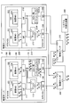
- FIG. 1 is a system configuration example of an information processing system 1 according to a first embodiment of the present invention.
- the information processing system 1 includes physical servers 100 and 200 as examples of information processing apparatuses, physical switches 300 and 310, and a system visualization apparatus 400.
- communication such as Ethernet (registered trademark); Ethernet (registered trademark), IEEE 802.3, FDDI (Fiber-Distributed Data Interface), PPP (Point to Point Protocol), etc. Protocol is adopted.
- FIG. 2 is a hardware configuration example of the physical server 100.
- the physical server 100 includes, for example, a CPU (Central Processing Unit) 100A, a drive device 100B, an auxiliary storage device 100D, a memory device 100E, an interface device 100F, an input device 100G, and a display device 100H. These components are connected via a bus, a serial line, or the like.
- a CPU Central Processing Unit
- the CPU 100A is, for example, a processor having a program counter, an instruction decoder, various arithmetic units, an LSU (Load Store Unit), a general-purpose register, and the like.
- LSU Load Store Unit
- the drive device 100B is a device that can read programs and data from the storage medium 100C.
- the storage medium 100C on which the program is recorded is mounted on the drive device 100B, the program is installed from the storage medium 100C to the auxiliary storage device 100D via the drive device 100B.
- the storage medium 100C is a portable storage medium such as a CD (Compact Disc), a DVD (Digital Versatile Disc), or a USB (Universal Serial Bus) memory.
- the auxiliary storage device 100D is, for example, an HDD (Hard Disk Drive) or a flash memory.
- the program can be installed by the interface device 100F being downloaded from another computer via a network and installed in the auxiliary storage device 100D.
- the network is the Internet, a LAN (Local Area Network), a wireless network, or the like.
- the program may be stored in advance in the auxiliary storage device 100D, a ROM (Read Only Memory), or the like when the physical server 100 is shipped.
- the information processing apparatus shown in FIG. 2 can function as the physical server 100 of this embodiment.
- the memory device 100E is, for example, a RAM (Random Access Memory) or an EEPROM (Electrically Erasable and Programmable Read Only Memory).
- the interface device 100F controls connection with the network.
- the input device 100G is, for example, a keyboard, a mouse, a button, a touch pad, a touch panel, a microphone, or the like.
- the display device 100H is a display device such as an LCD (Liquid Crystal Display) or a CRT (Cathode Ray Tube).
- the physical server 100 may include other types of output devices such as a printer and a speaker in addition to the display device 100H.
- the physical server 100 is controlled by a host OS (Operating System) 110 and a guest OS 120 operating on the host OS 110. Further, the physical server 100 includes a NIC (Network Interface Card) 130 connected to the physical switch 300 and a NIC 132 connected to the physical switch 310.
- a host OS Operating System
- a guest OS operating on the host OS 110.
- the physical server 100 includes a NIC (Network Interface Card) 130 connected to the physical switch 300 and a NIC 132 connected to the physical switch 310.
- NIC Network Interface Card
- the physical server 100 includes software means such as VIF (Virtual Interface) 111 and 112, a bridge 113, and a mirror unit 114 that are constructed on the host OS 110.
- VIF Virtual Interface
- the physical server 100 includes software means such as VIF (Virtual Interface) 111 and 112, a bridge 113, and a mirror unit 114 that are constructed on the host OS 110.
- the physical server 100 also has software means such as VMs (Virtual Machines) 121 and 122 constructed on the guest OS 120.
- the VMs 121 and 122 have virtual NICs 123 and 124, respectively.
- the physical server 200 is controlled by the host OS 210 and the guest OS 220 operating on the host OS 210.
- the physical server 200 also includes a NIC 230 connected to the physical switch 300 and a NIC 232 connected to the physical switch 310.
- the physical server 200 includes software means such as VIFs 211 and 212, a bridge 213, and a mirror unit 214 that are constructed on the host OS 210.
- the physical server 200 includes software means such as VMs 221 and 222 that are built on the guest OS 220.
- the VMs 221 and 222 have virtual NICs 223 and 224, respectively.
- Each of the VMs 121, 122, 221, and 222 functions as, for example, a Web server, an application server, a database server, and the like, and can provide various information services to client computers connected to the information processing system 1.
- two VMs exist on each physical server.
- the number of VMs present on each physical server may be any number.
- FIG. 3 is a diagram showing the contents of a MAC (Media Access Control) header MH and an IP header IH, which are packet header portions.
- MAC Media Access Control
- the packet “A” is transferred to the physical switch 300 by the virtual NIC 123, VIF 111, bridge 113, and NIC 130.
- the packet “A” is transferred to the VM 222 by the physical switch 300, the NIC 230, the bridge 213, the VIF 211, and the virtual NIC 223.
- the destination of the packet is determined by referring to the destination MAC address corresponding to each VIF in the bridges 113 and 213, the physical switch 300, and the like.
- communication between VMs on the same physical server is performed via the bridge 113 in packet units.
- the packet “B” is transmitted from the VM 121 to the VM 122, the packet “B” is transferred by the virtual NIC 123, VIF 111, bridge 113, VIF 112, and virtual NIC 124.
- the physical switch 300 has a MAC address / port correspondence table (MAC address table) (not shown) and performs packet transfer as described above. Further, the physical switch 300 has a port mirroring function, and performs processing (mirroring) for transmitting a copy of the transferred packet to the physical switch 310.
- MAC address table MAC address table
- the mirror unit 114 collects packets transmitted / received between VMs on the same physical server, and transmits the collected packets to the NIC 132.
- the NIC 132 transfers the packet input from the mirror unit 114 to the physical switch 310.
- the function of the mirror unit 214 is the same as that of the mirror unit 114.
- the mirror units 114 and 214 use packet buffers 114A and 214A, respectively.
- the physical switch 310 transmits the packet input from the physical switch 300 and the NICs 132 and 232 to the system visualization apparatus 400. Through these processes, packets transmitted / received between the physical servers and within the physical server are input to the system visualization device 400, and data of all packets transmitted / received within the information processing system 1 are collected in the system visualization device 400. .
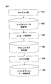
- FIG. 4 is a configuration example of the system visualization device 400.
- the system visualization device 400 includes a capture unit 410, a capture data storage unit 420, a message analysis unit 430, a protocol log storage unit 440, a log analysis unit 450, and a transaction data storage unit 460.
- the capture unit 410 receives the packet from the physical switch 310 and stores it in the capture data storage unit 420.
- the message analysis unit 430 extracts predetermined data from the packet stored in the capture data storage unit 420 and stores it in the protocol log storage unit 440.
- the log analysis unit 450 performs log analysis processing using the data stored in the protocol log storage unit 440 and stores it in the transaction data storage unit 460.
- the configuration of the system visualization device 400 is merely an example, and other modes may be adopted.
- FIG. 5 is a diagram conceptually showing an outline of processing by the mirror unit 114.
- the mirror unit 114 captures packets transmitted and received by all VMs of the physical server 100 (that is, packets passing through the VIFs 111 and 112), and packet buffers for each VM and each uplink / downlink. Store in the corresponding area of 114A.
- the mirror unit 114 distinguishes from an upstream packet transmitted to the VM 121, a downstream packet transmitted from the VM 121 to another VM, an upstream packet transmitted to the VM 122, and a downstream packet transmitted from the VM 122 to another VM.
- upstream packet transmitted to the VM 121 is abbreviated as “upstream packet of the VM 121”
- downstream packet transmitted from the VM 121 to another VM is abbreviated as “downstream packet of the VM 121”.
- upstream packet transmitted to the VM 122 is abbreviated as “upstream packet of VM 122”
- downstream packet transmitted from the VM 122 to another VM is abbreviated as “downstream packet of VM 122”.
- an upward arrow indicates an upstream packet
- a downward arrow indicates a downstream packet
- the upstream packet is transferred in a direction closer to the VM associated with the VIF (the VIF is in charge of packet transmission / reception) in the VIF where the packet is captured. It can be defined as a packet.
- the downstream packet can be defined as a packet that is transferred in a direction away from the VM associated with the VIF in the VIF where the packet is captured.
- VMs associated with the position where the packet was captured an example is when captured by the NIC 130 in the second embodiment.
- the “associated VM” may be read as “any one of the associated VMs”.
- VMs associated with the NIC 130 are all VMs (121, 122) on the physical server 100
- VMs associated with the NIC 230 are all VMs (221, 222) on the physical server 200.
- FIG. 6 is a flowchart showing a flow of processing for determining whether the mirror unit 114 is an upstream packet or a downstream packet. This flowchart is executed every time a packet is captured.
- the mirror unit 114 compares the destination MAC address in the MAC header of the captured packet with the MAC address of the VM corresponding to the VIF at which the packet is captured (S500). Then, the mirror unit 114 determines whether the destination MAC address matches the MAC address of the VM (S502).
- the mirror unit 114 determines that the packet is an uplink packet and stores the packet in the corresponding area of the packet buffer 114A (S504).
- the mirror unit 114 compares the source MAC address in the packet MAC header with the VM MAC address corresponding to the VIF at which the packet was captured (S506). Then, the mirror unit 114 determines whether or not the transmission source MAC address matches the VM MAC address (S508).
- the mirror unit 114 determines that the packet is a downlink packet, and stores the packet in the corresponding area of the packet buffer 114A (S510).
- the mirror unit 114 regards it as error data and deletes the packet (S512).
- the captured time is given to the packet stored in S504 or S510.
- the process of determining whether the mirror unit 114 is an upstream packet or a downstream packet may be performed using a transmission destination address or a transmission source address included in the IP header.
- the mirror unit 114 holds the IP address of each VM as table data in association with the VIF.
- FIG. 7 is another example of a flowchart showing a flow of processing for determining whether the mirror unit 114 is an upstream packet or a downstream packet. This flowchart is executed every time a packet is captured.
- the mirror unit 114 compares the destination address in the IP header of the captured packet with the IP address of the VM corresponding to the VIF that is the position where the packet was captured (S600). Then, the mirror unit 114 determines whether or not the transmission destination address matches the IP address of the VM (S602).
- the mirror unit 114 determines that the packet is an uplink packet and stores the packet in the corresponding area of the packet buffer 114A (S604).
- the mirror unit 114 compares the source address in the IP header of the captured packet with the IP address of the VM corresponding to the VIF at which the packet was captured ( S606). Then, the mirror unit 114 determines whether or not the transmission source address matches the IP address of the VM (S608).
- the mirror unit 114 determines that the packet is a downstream packet, and stores the packet in the corresponding area of the packet buffer 114A (S610).
- the mirror unit 114 regards it as error data and deletes the packet (S612).
- the captured time is given to the packet stored in S604 or S610.
- the mirror unit 114 compares the packets on the same physical server 100 as shown in the lower part of FIG.
- the packet transmitted / received between the VMs is extracted.
- the packet comparison is performed for each of the combination of the uplink packet of the VM 121 and the downlink packet of the VM 122, and the combination of the downlink packet of the VM 121 and the uplink packet of the VM 122.
- the mirror unit 114 compares the uplink packet of a certain VM with the downlink packets of all other VMs, and the downlink packet of the VM and all the other VMs. Comparison of uplink packets of VMs is performed for all VMs.
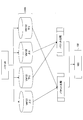
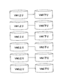
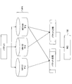
- FIG. 8 is a diagram illustrating a combination of packet comparisons performed when the number of VMs is three.
- FIG. 9 is a diagram illustrating a combination of packet comparisons performed when the number of VMs is four. 8 and 9, each VM is represented as VM1, VM2,.
- the mirror unit 114 performs ( n P 2 ) packet comparisons, where n is the number of VMs.
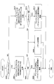
- FIG. 10 is a flowchart showing a processing flow when the mirror unit 114 performs packet comparison. This flow is repeatedly executed, for example, every predetermined time.
- the mirror unit 114 sequentially extracts one packet from the area where the “upstream packet of the VM 121” is stored in the packet buffer 114A (S700), and further extracts one packet from the area where the “downstream packet of the VM 122” is stored. (S702).
- the packet extraction order is determined according to, for example, FIFO (First In, First Out).
- the mirror unit 114 compares “ID”, “source address”, and “destination address”, which are information for identifying IP packets in the IP header in the packets extracted in S700 and S702 (S704). Then, the mirror unit 114 determines whether or not “ID”, “transmission source address”, and “transmission destination address” of the IP header all match (S706).
- the mirror unit 114 transmits one of the matched packet pairs (for example, a downstream packet) to the NIC 132. (S708). Then, the mirror unit 114 deletes the matched packet pair from the packet buffer 114A (S710). After the process of S710, the mirror unit 114 proceeds to S714, which will be described later, and executes the process.
- the mirror unit 114 determines whether or not all packets in the area storing “downstream packet of VM122” have been extracted in the loop processing related to “downstream packet of VM122”. Determination is made (S712).
- the loop processing regarding “downlink packet of VM 122” is loop processing in which the processing of S702 to S710 is repeated. In the loop processing, when all the packets of “downstream packet of VM 122” have not been extracted, the mirror unit 114 returns to S702, extracts the next packet from “downstream packet of VM 122”, and executes the processing after S704. .
- the mirror unit 114 determines whether or not all packets of “upstream packets of VM 121” have been extracted in the loop processing related to “upstream packets of VM 121” Is determined (S714).
- the loop process related to “upstream packet of VM 121” is a loop process in which the processes of S700 to S712 are repeated. In the loop processing, when all the packets of the “upstream packet of VM 121” have not been extracted, the mirror unit 114 returns to S700, extracts the next packet from the “upstream packet of VM 121”, and executes the processing after S702. .
- the mirror unit 114 sequentially extracts one packet from the area storing the “down packet of the VM 121” in the packet buffer 114A (S720). Further, the mirror unit 114 sequentially extracts one packet from the area storing the “upstream packet of the VM 122” (S722).
- the mirror unit 114 compares the “ID”, “source address”, and “destination address” of the IP header in the packets extracted in S720 and S722 (S724). Then, the mirror unit 114 determines whether or not “ID”, “transmission source address”, and “transmission destination address” of the IP header all match (S726).
- the mirror unit 114 selects one of the matched packet pairs (for example, a downstream packet) from the NIC 132. (S728). Then, the mirror unit 114 deletes the matched packet pair from the packet buffer 114A (S730).
- the mirror unit 114 determines whether or not all packets in the area storing “upstream packet of VM 122” have been extracted in the loop processing related to “upstream packet of VM 122”. Determination is made (S732).
- the loop process related to “upstream packet of VM 122” is a loop process in which the processes of S722 to S730 are repeated. In the loop process, when all the packets of the “upstream packet of VM 122” have not been extracted, the mirror unit 114 returns to S722, extracts the next packet, and executes the processes after S724.
- the mirror unit 114 determines whether or not all the packets of the “downstream packet of the VM 121” have been extracted in the loop processing related to the “downstream packet of the VM 121” (S734). ).
- the loop process related to “downstream packet of VM 121” is a loop process in which the processes of S720 to S732 are repeated. In the loop process, when all the packets of “downstream packet of VM 121” have not been extracted, the mirror unit 114 returns to S720, extracts the next packet, and executes the processes after S722.
- the mirror unit 114 deletes all packets stored in the packet buffer 114A that have been captured for a fixed time (S740).
- FIG. 10 the flowchart shown in FIG. 10 is for the case where the number of VMs existing on the physical server 100 is two. If the number n of VM present on the physical server 100 is three or more, a loop process such as S700 ⁇ S714, S720 ⁇ S734, may be performed as (n P 2).
- FIG. 11 is a diagram illustrating an information processing system 1 # and physical servers 100 # and 200 # according to a modification.
- “#” is added to the reference numerals of the corresponding components of the information processing system 1 and the physical servers 100 and 200 of the first embodiment.
- the mirror unit 114 # included in the physical server 100 # of the modified example collects all the packets passing through the VIFs 111 # and 112 # and transmits them to the NIC 132 #.
- data transmitted and received by a plurality of virtual machines within the same physical server can be output to an external device.
- the external device that is, the system visualization device, can collect both data transmitted and received by a plurality of virtual machines in the same physical server and data transmitted and received by the physical server to and from the external device.
- the information processing system and the physical server of the first embodiment shown in FIG. 1 can reduce the packet transfer load of the NIC 132 as compared with the information processing system and the physical server of the modified example. This is because the NIC 132 # transfers “A ⁇ B ⁇ D ⁇ C ⁇ ” in the physical server 100 # of the modified example, whereas the NIC 132 transfers “B ⁇ D ⁇ ” in the physical server 100 of the present embodiment. .
- the information processing system and the physical server of the first embodiment collect packets transmitted / received between VMs on the same physical server and transmit them to the NIC 132.
- Mirroring of packets transmitted / received between different physical servers is performed by the physical switch 300. I leave it to the function. For this reason, the packet transfer load in the NIC 132 is not excessive, and smooth information transmission / reception is realized. Further, it is not necessary to mount the NIC 132 having an excessively high function, and an increase in cost and weight can be suppressed. The same applies to the relationship between the mirror unit 214 and the NIC 232.
- FIG. 12 is a system configuration example of the information processing system 2 according to the second embodiment of the present invention.
- the information processing system 2 according to the second embodiment differs from the first embodiment in the processing content of the mirror unit. For this reason, not only the mirror units 114 * and 214 * but also the packet buffers used by the mirror units 114 * and 214 * A are denoted by the same reference numerals as those in the first embodiment. To explain.
- FIG. 13 is a diagram conceptually showing an outline of processing by the mirror unit 114 *.
- the mirror unit 114 * captures downlink packets transmitted / received by all VMs of the physical server 100 and downlink packets passing through the NIC 130, and stores them in the corresponding areas of the packet buffer 114 * A. To do. Specifically, the mirror unit 114 * distinguishes the downlink packet transmitted from the VM 121 to another VM, the downlink packet transmitted from the VM 122 to the other VM, and the downlink packet transferred from the NIC 130 to the physical switch 300. * Store in A.
- downlink packets transmitted from the VM 121 to other VMs are abbreviated as “downlink packets of the VM 121”, and downlink packets transmitted from the VM 122 to other VMs are abbreviated as “downlink packets of the VM 122”.
- downlink packets transmitted from the NIC 130 to the physical switch 300 are abbreviated as “downlink packet of NIC 130”.
- the “upstream packet” captured by the NIC 130 is a packet that the NIC 130 receives from the external device (physical switch 300), and the “downstream packet” is transmitted by the NIC 130 to the external device (physical switch 300). Packet.
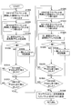
- FIG. 14 is a flowchart showing a processing flow in which the mirror unit 114 * selectively collects downstream packets. This flowchart is executed each time a packet is captured by the mirror unit 114 *.
- the mirror unit 114 * determines whether the packet is captured by the VIF 111 or the VIF 112 (S800).
- the mirror unit 114 * When the packet is captured by the VIF 111 or the VIF 112, the mirror unit 114 * performs the following processing.
- the mirror unit 114 * compares the source MAC address in the MAC header of the captured packet with the MAC address of the VM corresponding to the VIF at which the packet was captured (S802). Then, the mirror unit 114 * determines whether or not the source MAC address matches the VM MAC address (S804).
- the mirror unit 114 * determines that the packet is a downstream packet, and stores the packet in the corresponding area of the packet buffer 114 * A (S806).
- the mirror unit 114 * If the source MAC address and the VM MAC address do not match, the mirror unit 114 * considers it as an uplink packet or error data and deletes the packet (S808).
- the mirror unit 114 * performs the following processing.
- the mirror unit 114 * compares the source MAC address with the MAC addresses of all VMs (121, 122) of the physical server 100 (S810). Then, the mirror unit 114 * determines whether or not the source MAC address matches the MAC address of any VM (S812).
- the mirror unit 114 * determines that the packet is a downlink packet and stores the packet in the corresponding area of the packet buffer 114 * A (S814).
- the mirror unit 114 * If the source MAC address does not match the MAC addresses of all VMs, the mirror unit 114 * considers it as an upstream packet or error data and deletes the packet (S808).
- the captured time is given to the packet stored in S806 or S814.
- FIG. 15 is another example of a flowchart showing a processing flow in which the mirror unit 114 * selectively collects downstream packets. This flowchart is executed each time a packet is captured by the mirror unit 114 *.
- the mirror unit 114 * determines whether the packet is captured by the VIF 111 or the VIF 112 (S900).
- the mirror unit 114 * When the packet is captured by the VIF 111 or the VIF 112, the mirror unit 114 * performs the following processing. The mirror unit 114 * compares the transmission source address in the IP header of the captured packet with the IP address of the VM corresponding to the VIF that is the position where the packet was captured (S902). Then, the mirror unit 114 * determines whether or not the transmission source address matches the IP address of the VM (S904).
- the mirror unit 114 * determines that the packet is a downstream packet, and stores the packet in the corresponding area of the packet buffer 114 * A (S906).
- the mirror unit 114 * deletes the packet as an upstream packet or error data (S908).
- the mirror unit 114 * performs the following processing.
- the mirror unit 114 * compares the source address in the IP header of the captured packet with the IP addresses of all VMs (121, 122) that the physical server 100 has (S910). Then, the mirror unit 114 * determines whether or not the transmission source address matches the IP address of any VM (S912).
- the mirror unit 114 * determines that the packet is a downstream packet, and stores the packet in the corresponding area of the packet buffer 114 * A (S914).
- the mirror unit 114 * If the source address does not match all VM IP addresses, the mirror unit 114 * considers the packet to be an uplink packet or error data and deletes the packet (S908).
- the captured time is given to the packet stored in S906 or S914.
- the packet is compared between the VMs on the same physical server 100 as shown in the lower part of FIG. Extracted packets. The packet comparison is performed for each of the combination of the downlink packet of the VM 121 and the downlink packet passing through the NIC 130 and the combination of the downlink packet of the VM 122 and the downlink packet passing through the NIC 130.
- FIG. 16 is a flowchart showing a flow of processing when the mirror unit 114 * performs packet comparison. This flow is repeatedly executed, for example, every predetermined time.
- the mirror unit 114 * sequentially extracts one packet from the area storing the “downstream packet of the VM 121” in the packet buffer 114 * A (S1000), and sequentially collects the packets from the area storing the “downstream packet of the NIC 130”. (S1002).
- the packet extraction order is determined according to, for example, FIFO (First In, First Out).
- the mirror unit 114 * compares the “ID”, “source address”, and “destination address” of the IP header in the packets extracted in S1000 and S1002 (S1004). Then, the mirror unit 114 * determines whether or not the “ID”, “transmission source address”, and “transmission destination address” of the IP header all match (S1006).
- the mirror unit 114 * deletes the packet pair from the packet buffer 114 * A (S1008). After the process of S1008, the mirror unit 114 * proceeds to S1012 described later and executes the process.
- the loop processing relating to “the downstream packet of NIC 130” is a loop processing in which the processing of S1002 to S1008 is repeated. In the loop processing, when all the packets of “downstream packet of NIC 130” have not been extracted, the mirror unit 114 * returns to S1002, extracts the next packet from “downstream packet of NIC 130”, and executes the processing after S1004 To do.
- the mirror unit 114 * When all the packets of “the downstream packet of NIC 130” are taken out or after S1008, the mirror unit 114 * performs the following processing.
- the mirror unit 114 * determines whether or not all the packets of the “downstream packet of the VM 121” have been extracted in the loop processing related to the “downstream packet of the VM 121” (S1012).
- the loop processing related to “downstream packet of VM 121” is loop processing in which the processing of S1000 to S1010 is repeated. In the loop processing, when all the packets of “downstream packet of VM 121” are not extracted, the mirror unit 114 * returns to S1000, extracts the next packet from “downstream packet of VM 121”, and executes the processing from S1002 onward. To do.
- the mirror unit 114 * sequentially extracts one packet from the area storing the “downstream packet of the VM 122” in the packet buffer 114 * A (S1020). Next, the mirror unit 114 * sequentially takes out one packet from the area storing “the downstream packet of the NIC 130” (S1022).
- the mirror unit 114 * compares the “ID”, “source address”, and “destination address” of the IP header in the packets extracted in S1020 and S1022 (S1024). Then, the mirror unit 114 * determines whether or not the “ID”, “transmission source address”, and “transmission destination address” of the IP header all match (S1026).
- the mirror unit 114 * deletes the packet pair from the packet buffer 114 * A (S1028). After the process of S1028, the mirror unit 114 * proceeds to S1012 described later and executes the process.
- the loop processing related to “downlink packet of NIC 130” is loop processing in which the processing of S1022 to S1028 is repeated.
- the mirror unit 114 * returns to S1022, extracts the next packet from “downstream packet of NIC 130”, and executes the processing after S1024. To do.
- the mirror unit 114 * When all the packets of the “downstream packet of NIC 130” are taken out or after S1028, the mirror unit 114 * performs the following processing.
- the mirror unit 114 * determines whether or not all the packets of the “downstream packet of the VM 122” have been extracted in the loop processing related to the “downstream packet of the VM 122” (S1032).
- the loop process related to “downlink packet of VM 122” is a loop process in which the processes of S1020 to S1030 are repeated.
- the mirror unit 114 * returns to S1020, extracts the next packet from “downstream packet of VM 122”, and executes the processing from S1022.
- the mirror unit 114 * transmits, to all the packets stored in the packet buffer 114 * A, a packet that has passed for a certain period of time to the NIC 132. (S1040).
- the mirror unit 114 * includes a loop process such as S1000 ⁇ S1012, S1020 ⁇ S1032, it may be performed as (n P 2).
- the difference between the present embodiment and the information processing system 1 # and the physical servers 100 # and 200 # of the modification shown in FIG. 11 is the same as that of the first embodiment, and thus the description thereof is omitted.
- the number of capture positions increases, but the number of areas for storing captured packets can be reduced in the packet buffer 114 * A (see FIGS. 5 and 13).
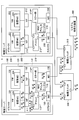
- FIG. 17 is a system configuration example of the information processing system 3 according to the third embodiment of the present invention.
- the host OSs 110 and 120 of the physical servers 100 and 200 include MAC address tables 115 and 125, respectively.
- the MAC address table 115 is table data set on the auxiliary storage device 100D or the memory device 100E.
- the MAC address table 215 is table data set on the auxiliary storage device 200D or the memory device 200E.
- the information processing system 3 according to the third embodiment of the present invention is different from the first embodiment in the processing contents of the bridge and the mirror unit.
- the bridges 113 ** and 213 ** and the mirror portions 114 ** and 214 ** are indicated, and the other components are denoted by the same reference numerals as those in the first embodiment.
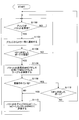
- FIG. 18 is a flowchart showing a flow of processing executed by the bridge 113 ** and the mirror unit 114 ** or the bridge 213 ** and the mirror unit 214 ** according to the third embodiment.
- the processing is performed by the bridge 113 ** and the mirror unit 114 **, but the same processing is performed by the bridge 213 ** and the mirror unit 214 **.
- the bridge 113 ** waits until a packet is received from the VIF 111 or 112 or the NIC 130 (S1100). When the packet is received, the bridge 113 ** notifies the mirror unit 114 ** to that effect (S1102).
- the mirror unit 114 ** determines whether the received port is a port corresponding to the VIF 111 or 112 among the virtual ports of the bridge 113 ** (S1104).
- the mirror unit 114 ** If the received virtual port of the bridge 113 ** is not a port corresponding to the VIF 111 or 112, the mirror unit 114 ** returns to S1100 and waits until the bridge 113 ** receives a packet.
- the mirror unit 114 ** searches the MAC address table 115 using the packet destination MAC address. (S1106).
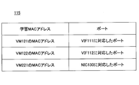
- FIG. 19 is an example of data stored as the MAC address table 115.
- the MAC address table 115 stores the MAC address learned by the bridge 113 ** (learned MAC header address) in association with the virtual port.
- the mirror unit 114 ** determines whether or not the transmission destination MAC address of the packet is registered in the MAC address table 115 (S1108).
- the mirror unit 114 ** copies the packet from the bridge 113 ** and transmits the copied packet to the NIC 132 (S1110).
- the bridge 113 ** has a function of registering the source MAC address of the received packet in the MAC address table 115 in association with the virtual port that has received the packet.
- the mirror unit 114 ** determines whether or not the port corresponding to the destination MAC address in the MAC address table 115 is a port corresponding to the VIF 111 or 112 (S1112). .
- the mirror unit 114 ** returns to S1100 and waits until the bridge 113 ** receives a packet.
- the mirror unit 114 ** copies the packet from the bridge 113 ** and transmits the copied packet to the NIC 132 (S1110).
- the packet B shown in FIG. 17 is transmitted from the VM 121 to the VM 122 as a result of the processing, if the MAC address of the VM 122 that is the transmission destination MAC address of the packet B is registered in the MAC address table 115, the packet B is transmitted to the NIC 132. Is sent. Similarly, when the MAC address of the VM 122 is not registered in the MAC address table 115, the packet B is transmitted to the NIC 132 in the same manner. In the latter case, since the MAC address of the VM 122 is registered in the MAC address table 115, a packet is transmitted to the NIC 132 by obtaining a positive determination in S1112 in the subsequent processing.
- the packet A shown in FIG. 17 is transmitted from the VM 121 to the VM 221.
- the port corresponds to the NIC 130, and the packet A is not transmitted to the NIC 132.
- the packet A is transmitted to the NIC 132.
- the packet A is transmitted to the system visualization device 400 in duplicate, and thereafter, since it is registered in the MAC address table 115, the duplication is It is within an acceptable range.
- the packet C is transmitted from the VM 221 to the VM 121, the packet C is received by the port corresponding to the NIC 130 in the bridge 113 **, and therefore the packet C is not transmitted to the NIC 132.
- the difference between the present embodiment and the information processing system 1 # and the physical servers 100 # and 200 # of the modification shown in FIG. 11 is the same as that of the first embodiment, and thus the description thereof is omitted.
- the information processing apparatus of the third embodiment may collect packets using IP addresses instead of MAC addresses, as in the first embodiment.
- the mirror unit 114 * in the second embodiment captures downstream packets transmitted and received by all VMs and downstream packets passing through the NIC 130, and excludes those whose contents match. Absent.
- the mirror unit 114 * in the second embodiment may capture upstream packets transmitted / received by all VMs and upstream packets that pass through the NIC 130, and may transmit packets to the NIC 132 by excluding those that match. .
- the physical switches 300 and 310 may be integrated into a physical switch.
- the arrangement of the OS and VM in each embodiment is an arbitrary matter, and the present invention can be applied if a plurality of VMs exist on the information processing apparatus (physical server).
- each physical server separates the NIC that performs transmission / reception with the external device and the NIC that transmits the packet collected by the mirror unit, but the transmission / reception packet with the external device and the packet collected by the mirror unit using the same NIC Both of them may be handled.
- the present invention can be used in the computer manufacturing industry, the computer software industry, the information service providing industry, and the like.
Landscapes
- Engineering & Computer Science (AREA)
- Computer Networks & Wireless Communication (AREA)
- Signal Processing (AREA)
- Software Systems (AREA)
- Theoretical Computer Science (AREA)
- Data Mining & Analysis (AREA)
- Physics & Mathematics (AREA)
- General Engineering & Computer Science (AREA)
- General Physics & Mathematics (AREA)
- Data Exchanges In Wide-Area Networks (AREA)
Abstract
La présente invention porte sur un dispositif de traitement d'informations qui comporte une unité de collecte de données pour collecter des données qui sont transmises et reçues à l'intérieur du même dispositif physique par une pluralité de machines virtuelles (VM) exécutées à l'intérieur du dispositif physique, et une unité de communication qui délivre des données collectées par l'unité de collecte de données à un dispositif externe.
Priority Applications (4)
| Application Number | Priority Date | Filing Date | Title |
|---|---|---|---|
| PCT/JP2012/051880 WO2013111343A1 (fr) | 2012-01-27 | 2012-01-27 | Dispositif de traitement d'informations, système de traitement d'informations, procédé de délivrance de données de communication et programme de délivrance de données de communication |
| EP12866923.1A EP2809035A4 (fr) | 2012-01-27 | 2012-01-27 | Dispositif de traitement d'informations, système de traitement d'informations, procédé de délivrance de données de communication et programme de délivrance de données de communication |
| JP2013555095A JP5825360B2 (ja) | 2012-01-27 | 2012-01-27 | 情報処理装置、情報処理システム、通信データ出力方法、及び通信データ出力プログラム |
| US14/322,979 US9703580B2 (en) | 2012-01-27 | 2014-07-03 | Information processing apparatus, information processing system, and communication data output method |
Applications Claiming Priority (1)
| Application Number | Priority Date | Filing Date | Title |
|---|---|---|---|
| PCT/JP2012/051880 WO2013111343A1 (fr) | 2012-01-27 | 2012-01-27 | Dispositif de traitement d'informations, système de traitement d'informations, procédé de délivrance de données de communication et programme de délivrance de données de communication |
Related Child Applications (1)
| Application Number | Title | Priority Date | Filing Date |
|---|---|---|---|
| US14/322,979 Continuation US9703580B2 (en) | 2012-01-27 | 2014-07-03 | Information processing apparatus, information processing system, and communication data output method |
Publications (1)
| Publication Number | Publication Date |
|---|---|
| WO2013111343A1 true WO2013111343A1 (fr) | 2013-08-01 |
Family
ID=48873104
Family Applications (1)
| Application Number | Title | Priority Date | Filing Date |
|---|---|---|---|
| PCT/JP2012/051880 WO2013111343A1 (fr) | 2012-01-27 | 2012-01-27 | Dispositif de traitement d'informations, système de traitement d'informations, procédé de délivrance de données de communication et programme de délivrance de données de communication |
Country Status (4)
| Country | Link |
|---|---|
| US (1) | US9703580B2 (fr) |
| EP (1) | EP2809035A4 (fr) |
| JP (1) | JP5825360B2 (fr) |
| WO (1) | WO2013111343A1 (fr) |
Cited By (1)
| Publication number | Priority date | Publication date | Assignee | Title |
|---|---|---|---|---|
| WO2018179413A1 (fr) * | 2017-03-31 | 2018-10-04 | 三菱電機株式会社 | Dispositif de traitement d'informations et procédé de traitement d'informations |
Families Citing this family (5)
| Publication number | Priority date | Publication date | Assignee | Title |
|---|---|---|---|---|
| JP6041636B2 (ja) * | 2012-11-26 | 2016-12-14 | キヤノン株式会社 | 情報処理装置、情報処理装置の制御方法、及びプログラム |
| US9262090B2 (en) * | 2013-02-26 | 2016-02-16 | Lenovo Enterprise Solutions (Singapore) Pte. Ltd. | Asynchronous data mirroring in memory controller |
| KR102209525B1 (ko) * | 2014-01-06 | 2021-01-29 | 삼성전자주식회사 | 마이크로 서버, mac 주소 할당 방법 및 컴퓨터 판독가능 기록매체 |
| JP6248763B2 (ja) * | 2014-03-31 | 2017-12-20 | 富士通株式会社 | キャプチャポイント決定方法、キャプチャポイント決定システムおよびキャプチャポイント決定プログラム |
| JP7003562B2 (ja) * | 2017-10-16 | 2022-01-20 | 富士通株式会社 | ミラーパケット制御プログラム、ミラーパケット制御方法、およびミラーパケット制御装置 |
Citations (3)
| Publication number | Priority date | Publication date | Assignee | Title |
|---|---|---|---|---|
| JP2011182211A (ja) | 2010-03-02 | 2011-09-15 | Fujitsu Ltd | バッファ管理プログラム及び方法、並びにメッセージ分析装置 |
| JP2012004781A (ja) * | 2010-06-16 | 2012-01-05 | Fujitsu Ltd | 構成情報取得方法、仮想プローブおよび構成情報取得制御装置 |
| JP2012048629A (ja) * | 2010-08-30 | 2012-03-08 | Fujitsu Ltd | 仮想マシン管理プログラム、仮想マシン管理方法、および仮想マシン管理装置 |
Family Cites Families (15)
| Publication number | Priority date | Publication date | Assignee | Title |
|---|---|---|---|---|
| US6041042A (en) * | 1997-05-27 | 2000-03-21 | Cabletron Systems, Inc. | Remote port mirroring system and method thereof |
| US7782784B2 (en) * | 2003-01-10 | 2010-08-24 | Cisco Technology, Inc. | Port analyzer adapter |
| US7626938B1 (en) * | 2005-03-31 | 2009-12-01 | Marvell Israel (M.I.S.L) Ltd. | Local area network switch using control plane packet mirroring to support multiple network traffic analysis devices |
| JP4570527B2 (ja) * | 2005-07-20 | 2010-10-27 | 富士通株式会社 | システム性能監視プログラム及びシステム性能監視方法 |
| US8050185B2 (en) * | 2005-08-24 | 2011-11-01 | Hewlett-Packard Development Company, L.P. | Sampling of network traffic based on CAM lookup |
| US8397284B2 (en) * | 2006-01-17 | 2013-03-12 | University Of Maryland | Detection of distributed denial of service attacks in autonomous system domains |
| US20070266433A1 (en) * | 2006-03-03 | 2007-11-15 | Hezi Moore | System and Method for Securing Information in a Virtual Computing Environment |
| JP5217886B2 (ja) * | 2008-10-14 | 2013-06-19 | 富士通株式会社 | ループバック装置及びミラーリング方法 |
| EP2401683A4 (fr) * | 2009-02-27 | 2015-07-29 | Broadcom Corp | Procédé et système de réseautage de machines virtuelles |
| US8265075B2 (en) * | 2009-03-16 | 2012-09-11 | International Business Machines Corporation | Method and apparatus for managing, configuring, and controlling an I/O virtualization device through a network switch |
| US9063769B2 (en) * | 2010-02-04 | 2015-06-23 | Telefonaktiebolaget Lm Ericsson (Publ) | Network performance monitor for virtual machines |
| US8520540B1 (en) * | 2010-07-30 | 2013-08-27 | Cisco Technology, Inc. | Remote traffic monitoring through a network |
| US9191327B2 (en) * | 2011-02-10 | 2015-11-17 | Varmour Networks, Inc. | Distributed service processing of network gateways using virtual machines |
| US9110703B2 (en) * | 2011-06-07 | 2015-08-18 | Hewlett-Packard Development Company, L.P. | Virtual machine packet processing |
| WO2014000297A1 (fr) * | 2012-06-30 | 2014-01-03 | 华为技术有限公司 | Procédé et dispositif de surveillance de port virtuel |
-
2012
- 2012-01-27 EP EP12866923.1A patent/EP2809035A4/fr not_active Withdrawn
- 2012-01-27 JP JP2013555095A patent/JP5825360B2/ja active Active
- 2012-01-27 WO PCT/JP2012/051880 patent/WO2013111343A1/fr active Application Filing
-
2014
- 2014-07-03 US US14/322,979 patent/US9703580B2/en active Active
Patent Citations (3)
| Publication number | Priority date | Publication date | Assignee | Title |
|---|---|---|---|---|
| JP2011182211A (ja) | 2010-03-02 | 2011-09-15 | Fujitsu Ltd | バッファ管理プログラム及び方法、並びにメッセージ分析装置 |
| JP2012004781A (ja) * | 2010-06-16 | 2012-01-05 | Fujitsu Ltd | 構成情報取得方法、仮想プローブおよび構成情報取得制御装置 |
| JP2012048629A (ja) * | 2010-08-30 | 2012-03-08 | Fujitsu Ltd | 仮想マシン管理プログラム、仮想マシン管理方法、および仮想マシン管理装置 |
Non-Patent Citations (2)
| Title |
|---|
| See also references of EP2809035A4 |
| SHUICHIRO AIBA ET AL.: "Traffic Control of Virtual Machine using Flow-based Analysis", IEICE TECHNICAL REPORT, ICM2010-36, vol. 110, no. 375, 13 January 2011 (2011-01-13), pages 17 - 22, XP008171913 * |
Cited By (2)
| Publication number | Priority date | Publication date | Assignee | Title |
|---|---|---|---|---|
| WO2018179413A1 (fr) * | 2017-03-31 | 2018-10-04 | 三菱電機株式会社 | Dispositif de traitement d'informations et procédé de traitement d'informations |
| US10715433B2 (en) | 2017-03-31 | 2020-07-14 | Mitsubishi Electric Corporation | Information processing apparatus and information processing method |
Also Published As
| Publication number | Publication date |
|---|---|
| US20140317623A1 (en) | 2014-10-23 |
| JPWO2013111343A1 (ja) | 2015-05-11 |
| JP5825360B2 (ja) | 2015-12-02 |
| EP2809035A1 (fr) | 2014-12-03 |
| EP2809035A4 (fr) | 2015-06-03 |
| US9703580B2 (en) | 2017-07-11 |
Similar Documents
| Publication | Publication Date | Title |
|---|---|---|
| JP5825360B2 (ja) | 情報処理装置、情報処理システム、通信データ出力方法、及び通信データ出力プログラム | |
| US8634437B2 (en) | Extended network protocols for communicating metadata with virtual machines | |
| US8990433B2 (en) | Defining network traffic processing flows between virtual machines | |
| US8572609B2 (en) | Configuring bypass functionality of a network device based on the state of one or more hosted virtual machines | |
| US8086739B2 (en) | Method and system for monitoring virtual wires | |
| US7965714B2 (en) | Method and system for offloading network processing | |
| Yang et al. | Implementation of a real-time network traffic monitoring service with network functions virtualization | |
| US20110004876A1 (en) | Network Traffic Processing Pipeline for Virtual Machines in a Network Device | |
| US20190190949A1 (en) | System for distributing virtual entity behavior profiling in cloud deployments | |
| JP5809189B2 (ja) | 通信経路切替装置、通信経路切替方法、および通信経路切替プログラム | |
| TWI603206B (zh) | Server cluster based data processing method and cluster based data processing system | |
| US10164822B2 (en) | Flatnet failover control | |
| CN113162795A (zh) | 用于通信网络的设备 | |
| JP5545162B2 (ja) | 監視プログラム、監視装置、および監視方法 | |
| JP2014048900A (ja) | 計算機システム及びパケット転送方法 | |
| JP5024394B2 (ja) | システム可視化プログラム、方法及び装置 | |
| US20160285705A1 (en) | Large-scale passive network monitoring using multiple tiers of ordinary network switches | |
| JP2013223191A (ja) | 通信システム、制御装置、パケット採取方法及びプログラム | |
| JP2016144186A (ja) | 通信情報制御装置、中継システム、通信情報制御方法、および、通信情報制御プログラム | |
| JP2004088200A (ja) | プロセスマイグレーション方法、通信システム、計算機 | |
| JP7082884B2 (ja) | 通信装置、通信システム、及び通信方法 | |
| JP6439701B2 (ja) | 通信装置、パケット監視方法及びコンピュータプログラム | |
| JP6496860B2 (ja) | 監視システム、監視方法および監視プログラム | |
| JP6317833B1 (ja) | 監視システム、監視方法、情報処理装置および監視プログラム | |
| US20100312866A1 (en) | Redundancy pair detecting method, communication device and recording medium for recording redundancy pair detection program |
Legal Events
| Date | Code | Title | Description |
|---|---|---|---|
| 121 | Ep: the epo has been informed by wipo that ep was designated in this application |
Ref document number: 12866923 Country of ref document: EP Kind code of ref document: A1 |
|
| ENP | Entry into the national phase |
Ref document number: 2013555095 Country of ref document: JP Kind code of ref document: A |
|
| WWE | Wipo information: entry into national phase |
Ref document number: 2012866923 Country of ref document: EP |
|
| NENP | Non-entry into the national phase |
Ref country code: DE |